Embed Size (px)
Citation preview

PROGRAMMING

Each PLC manufacturer offers a different set of instructions within its PLC family. Many of these instruction sets are not applicable to other PLCs, and there is no easy way to translate an already written PLC program to another brand of PLC’s programming format.
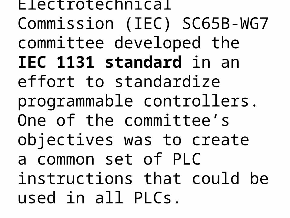
The International Electrotechnical Commission (IEC) SC65B-WG7committee developed the IEC 1131 standard in an effort to standardizeprogrammable controllers. One of the committee’s objectives was to createa common set of PLC instructions that could be used in all PLCs.

PLC Programming Method• Ladder Diagram (LD) —a graphical depiction of aprocess with rungs of logic, similar to the relay ladderlogic schemes that were replaced by PLCs.• Function Block Diagram (FBD) —a graphical depictionof process fl ow using simple and complexinterconnecting blocks.• Sequential Function Chart (SFC) —a graphicaldepiction of interconnecting steps, actions, andtransitions.• Instruction List (IL) —a low-level, text-basedlanguage that uses mnemonic instructions.• Structured Text (ST) —a high-level, text-based languagesuch as BASIC, C, or PASCAL specifi callydeveloped for industrial control applications

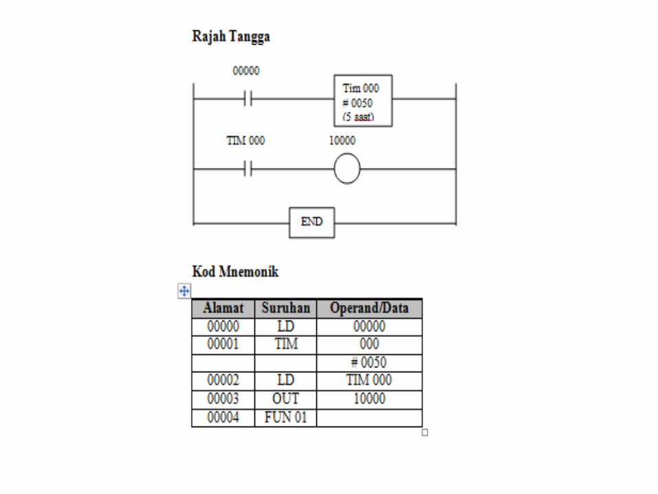
•Ladder Diagram & Mnemonic Code

Ladder Diagram & Mnemonic Code


Ladder Diagram & Function Block Diagram (FBD)
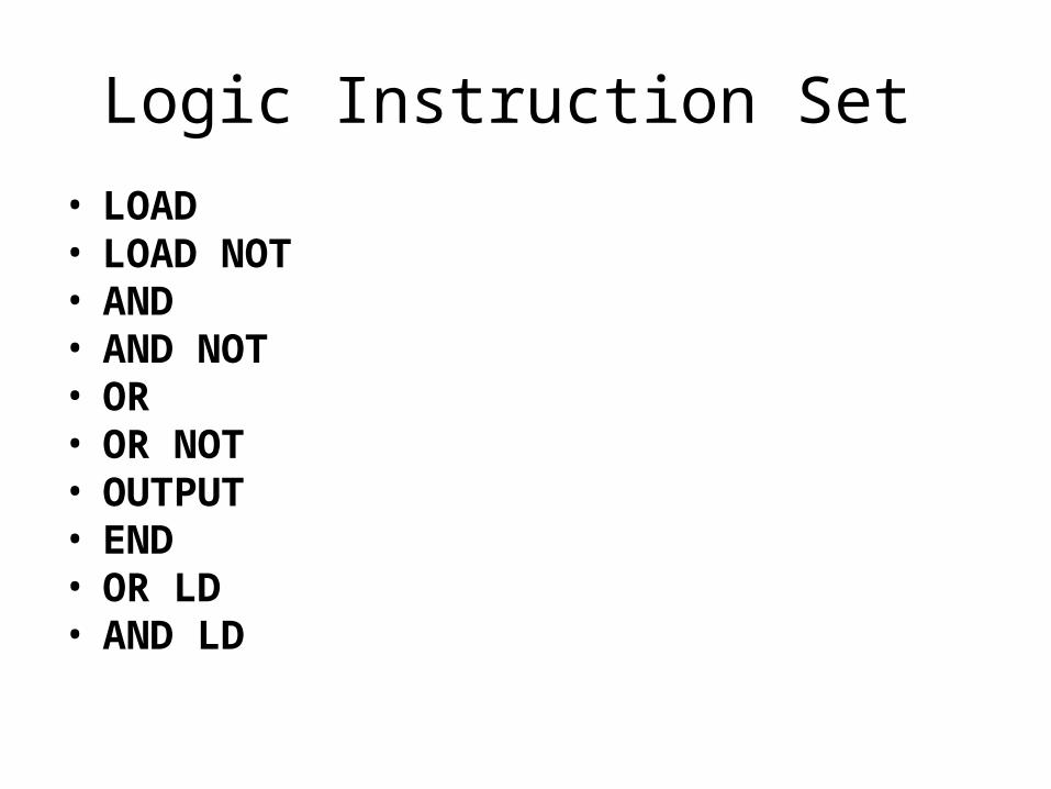
Logic Instruction Set • LOAD• LOAD NOT• AND• AND NOT• OR• OR NOT• OUTPUT• END• OR LD• AND LD
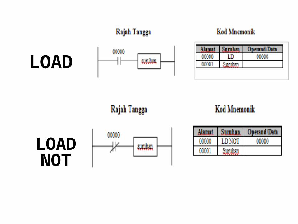
LOAD
LOAD NOT

AND
AND NOT

OR
OR NOT

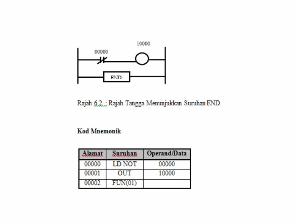
END
OUT

OR LD
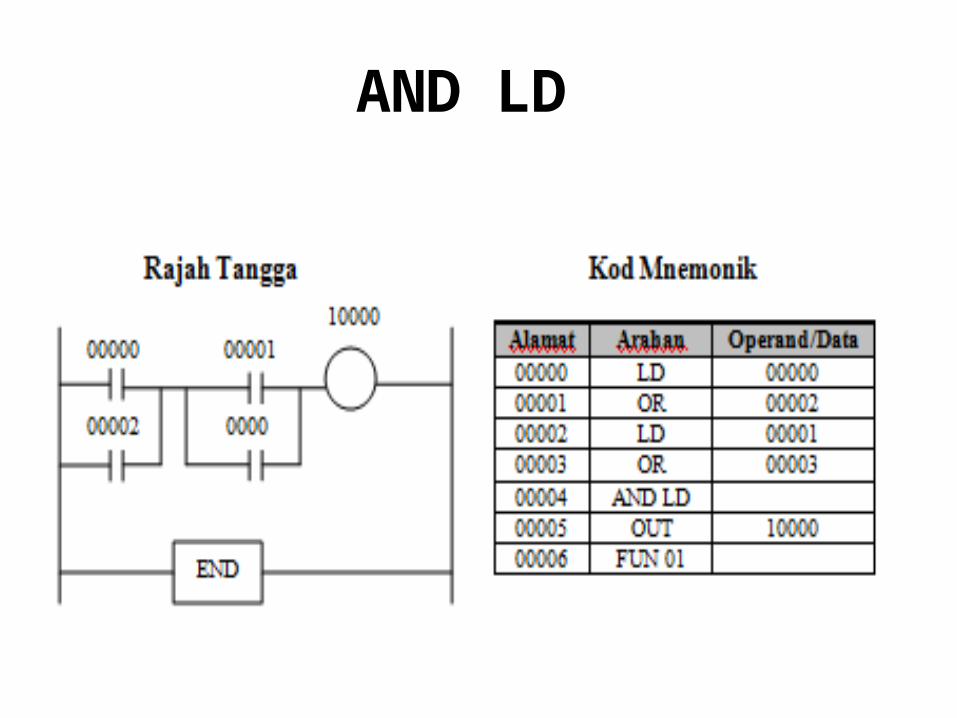
AND LD

Sequential Instruction Set
- NO OPERATION- END- INTERLOCK- JUMP- KEEP- SET/RESET- DIFFERENTIATE UP / DOWN

NO OPERATION – NOP ( 00 )
• This instruction does not have a ladder diagram symbols and will not be doing any operations.
• When this instruction is removed memory will be displayed in the PLC programming console.

END – END(01)
• Act as the last instruction for each program• No instruction will be written after the END
directive (01) implemented.• If no instructions END (01) in the program
would be implemented then no instructions and verse NO END LIST will appear on the console screen PLC programming.
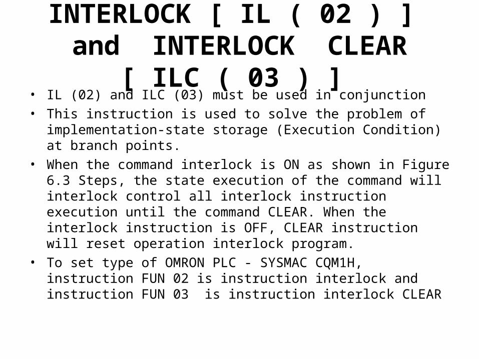
INTERLOCK [ IL ( 02 ) ] and INTERLOCK CLEAR [ ILC ( 03 ) ]
• IL (02) and ILC (03) must be used in conjunction• This instruction is used to solve the problem of implementation-state
storage (Execution Condition) at branch points.• When the command interlock is ON as shown in Figure 6.3 Steps, the
state execution of the command will interlock control all interlock instruction execution until the command CLEAR. When the interlock instruction is OFF, CLEAR instruction will reset operation interlock program.
• To set type of OMRON PLC - SYSMAC CQM1H, instruction FUN 02 is instruction interlock and instruction FUN 03 is instruction interlock CLEAR

Suruhan LD 00000IL(02)
Suruhan LD 00001Masukan
Suruhan OUT 10000Keluaran
ON ON ONOFF OFF
OFF ON OFFOFF OFF

JUMP [ JMP (04) ] DAN JUMP END [ JME (05) ]
• Instruction JMP (04) is usually used in pairs with instructions JME (05) to produce the jump.• JMP (04) is the command to determine the starting point jump while JME (05) is the direction to be the direction of the jump.• When the instruction JMP (04) is ON, no jump will occur and the program will be implemented as written.• When the instruction JMP (04) is OFF, a jump to the instruction JME (05) that have the same number will be done. Further instructions are after directions JME (05) will be implemented.• Instructions JUMP and JUMP END can use the numbers from the range of 00 to 99.• To set type of OMRON PLC - SYSMAC CQM1H, JUMP instruction is instruction FUN 04 and JUMP END instruction is instruction FUN 05.


KEEP – KEEP (11)• KEEP instruction is used to maintain the status bit operation based on two
state implementation (execution condition).• KEEP (11) operates as the relay latches (latching relay) which is set by S
and reset by R.• When S is in the ON state, operating instructions specified output will
remain in a state of ON and ON until reset, regardless of whether S is ON or OFF.
• When R is in the ON state, operating instructions specified output will turn OFF and remain in the OFF state until reset, regardless of whether R is ON or OFF.
• To set type of OMRON PLC - SYSMAC CQM1H, instruction KEEP is instruction FUN 11.


SET AND RESET
• SET and RESET instruction will change the status of bit operations only when ON execution condition.
• In the OFF condition, the instructions will not change the status of bit operations.

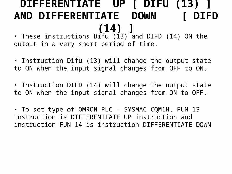
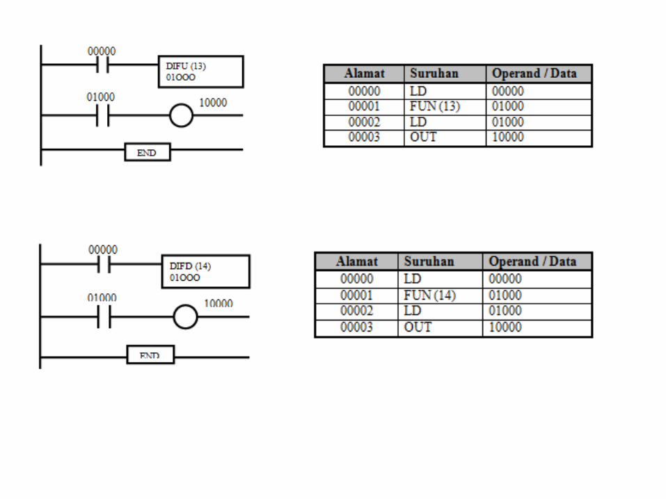
DIFFERENTIATE UP [ DIFU (13) ] AND DIFFERENTIATE DOWN [ DIFD (14) ]
• These instructions Difu (13) and DIFD (14) ON the output in a very short period of time.
• Instruction Difu (13) will change the output state to ON when the input signal changes from OFF to ON.
• Instruction DIFD (14) will change the output state to ON when the input signal changes from ON to OFF.
• To set type of OMRON PLC - SYSMAC CQM1H, FUN 13 instruction is DIFFERENTIATE UP instruction and instruction FUN 14 is instruction DIFFERENTIATE DOWN

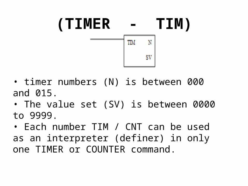
(TIMER - TIM)
• timer numbers (N) is between 000 and 015.• The value set (SV) is between 0000 to 9999.• Each number TIM / CNT can be used as an interpreter (definer) in only one TIMER or COUNTER command.


(COUNTER - CNT)
• Number TIM / CNT can be used as an interpreter (definer) only either in the timer or counter. • The numbers count ranges from 000 to 015. • Counters are used to calculate the count down from the set (SV) when the execution condition (execution condition) on the pulse off (CP), changed from OFF to ON. • The value set (SV) ranges from 0000 to 9999. • The counter resets the reset input (R).


The end…
• Quiz• Practical• End of Chapter