Embed Size (px)
Citation preview

1
Programming for Symbian OS

2
Publikacja powstała w wyniku projektu zrealizowanego przy wspar-ciu fi nansowym Komisji Europejskiej w ramach programu „Uczenie się przez całe życie”.Publikacja odzwierciedla jedynie stanowisko autorów i Komisja Europej-ska ani Narodowa Agencja nie ponoszą odpowiedzialności za umiesz-czoną w niej zawartość merytoryczną oraz za sposób wykorzystania za-wartych w niej informacji.

3
Programming for Symbian OS
Kraków 2010

4
Edited by prof. dr hab. inż. Andrzej Pach, Akademia Górniczo-Hutnicza im. Stanisława Staszica w Krakowie
Authors:Universidad de Málaga, España: Almudena Díaz Zayas, Jesús Martínez Cruz, Pedro Merino Gómez, Laura Panizo Jaime, Álvaro M. Recio Pérez, Alberto Salmerón MorenoAkademia Górniczo-Hutnicza im. Stanisława Staszica w Krakowie, Polska: Jacek Dańda, Jerzy Domżał, Norbert Rapacz, Marek Sikora, Robert WójcikUniversidad Politécnica de Cartagena, España: Esteban Egea-Lopez, Juan Carlos Sánchez-Aarnoutse, Juan José Alcaraz-Espín, Felipe García-Sánchez, Javier Vales-Alonso, Joan García-Haro.
Redakcja techniczna i projekt okładki: Paweł Kremer, Katarzyna Włodkowska-Łoziak – ANGLIKARNIA
Korekta: Katarzyna Włodkowska-Łoziak – ANGLIKARNIA
Zdjęcie na okładce: © Scanrail - Fotolia.com
ISBN: 978-83-88309-72-4

5
Contents
1. Introduction . . . . . . . . . . . . . . . . . . . . . . . . . . 71.1 Symbian history. . . . . . . . . . . . . . . . . . . . . . . 71.2 On Symbian Devices . . . . . . . . . . . . . . . . . . . 101.3 Memory. . . . . . . . . . . . . . . . . . . . . . . . . . 101.4 Symbian Architecture . . . . . . . . . . . . . . . . . . . 141.5 Kernel. . . . . . . . . . . . . . . . . . . . . . . . . . . 201.6 Dynamic Link Libraries . . . . . . . . . . . . . . . . . . 231.7 ECOM: Plug-ins in the Symbian OS . . . . . . . . . . . . 271.8 Security in the Symbian OS . . . . . . . . . . . . . . . . 291.9 Binary Types . . . . . . . . . . . . . . . . . . . . . . . 31
2. Building and installing an application . . . . . . . . . . . . 352.1 Project structure. . . . . . . . . . . . . . . . . . . . . . 352.2 Project fi le (mmp) and other fi les (pkg, sis, rss, rls, etc) . . 362.3 Certifi cates . . . . . . . . . . . . . . . . . . . . . . . . 402.4 Building from command line . . . . . . . . . . . . . . . 412.5 Installing applications . . . . . . . . . . . . . . . . . . . 422.6 The Carbide.c++ IDE! . . . . . . . . . . . . . . . . . . 43
3. Types, classes and Symbian conventions . . . . . . . . . . . 553.1 Naming conventions . . . . . . . . . . . . . . . . . . . 553.2 Built-in data types . . . . . . . . . . . . . . . . . . . . . 633.3 Descriptors . . . . . . . . . . . . . . . . . . . . . . . . 64
4. Memory management . . . . . . . . . . . . . . . . . . . . 774.1 Stack and heap . . . . . . . . . . . . . . . . . . . . . . 794.2 Cleanup Stack . . . . . . . . . . . . . . . . . . . . . . 804.3 Two-phase constructor . . . . . . . . . . . . . . . . . . 824.4 Rules for handling memory for objects of different types of classes . . . . . . . . . . . . . . . . . . 854.5 Classes other than CBase . . . . . . . . . . . . . . . . . 864.6 Example 3. . . . . . . . . . . . . . . . . . . . . . . . . 904.7 Summary . . . . . . . . . . . . . . . . . . . . . . . . . 974.8 Handling Errors . . . . . . . . . . . . . . . . . . . . . . 984.9 Useful tools to analyze panics. . . . . . . . . . . . . . . 994.10 Source materials . . . . . . . . . . . . . . . . . . . . . 99

6
5. Application design in Symbian . . . . . . . . . . . . . . . .1015.1 Symbian binaries and applications . . . . . . . . . . . .1015.2 Architecture of Symbian applications . . . . . . . . . . .1025.3 Developing an engine as a DLL . . . . . . . . . . . . . .108
6. Client-Server architecture . . . . . . . . . . . . . . . . . .1156.1 Introduction to the client-server architecture . . . . . . .1156.2 Using client-side APIs . . . . . . . . . . . . . . . . . . .1176.3 File server. . . . . . . . . . . . . . . . . . . . . . . . .1186.4 Symbian Socket API. . . . . . . . . . . . . . . . . . . .1206.5. Example: TCP/IP Client connection using Active-Objects 129
7. Active objects . . . . . . . . . . . . . . . . . . . . . . . .1377.1 Event-driven multi-tasking. . . . . . . . . . . . . . . . .1377.2 Introduction to active object framework. . . . . . . . . .1387.3 Active Object Framework life cycle . . . . . . . . . . . .1427.4 Summary . . . . . . . . . . . . . . . . . . . . . . . . .150
8. Graphical user interface . . . . . . . . . . . . . . . . . . .1518.1 Application framework . . . . . . . . . . . . . . . . . .1518.2 GUI application step-by-step . . . . . . . . . . . . . . .1548.3 Views and graphics . . . . . . . . . . . . . . . . . . . .1578.4 Events. . . . . . . . . . . . . . . . . . . . . . . . . . .1608.5 Resources . . . . . . . . . . . . . . . . . . . . . . . . .1618.6 Dialogs . . . . . . . . . . . . . . . . . . . . . . . . . .1628.7 Introduction to Carbide.c++ . . . . . . . . . . . . . . .1638.8 Data Persistence . . . . . . . . . . . . . . . . . . . . .179
Endnotes . . . . . . . . . . . . . . . . . . . . . . . . . . . . .189

7
Introduction
1.1 Symbian history
The Symbian Operating System (Symbian OS) is a robust, fully-featured operating system which runs on the majority of today’s smartphones. The market demand for smartphones is constantly growing and the devices become more powerful, more reliable and widely used. But what exactly is a smartphone and how is it different from a regular mobile phone? A mobile phone is a device that fi ts into your pocket and lets you commu-nicate with other people around the globe. Laptops and PDAs are mobile computers allowing you to perform most actions that you normally do on regular PCs. Smartphones are, basically, a combination of both: they can run applications such as organizers, games and communication programs, as well as make telephone calls.
The main goal of smartphones is to limit the number of devices that you need to carry and to combine their functions in an effi cient way. For instance, you are able to keep your private contact information in one place and have an easy access to calling, texting, e-mailing or sending fi les to each person from the same device. Many examples could be men-tioned here; however, the full scope is virtually unlimited.
In order to provide such a broad functionality smartphones must be running an operating system, much like regular PCs. An operating sys-tem (commonly abbreviated to OS or O/S) is an interface between hard-ware and software in a computer system. The OS is responsible for the management and coordination of activities and the sharing of the limited resources of the computer. Also it is a software that controls the execution of computer programs and may provide various services. The Symbian Operating System is such an OS, except it is optimized for mobile devices.
Although Symbian OS smartphones are pre-equipped with a variety of useful applications, perhaps their biggest asset is the fact that users are able to download, install and uninstall applications written by third-party developers, much like we install applications on our PCs or laptops. Moreover, the demand for Symbian OS applications is growing, and is growing rapidly. The scope of applications ranges from productivity and management, through communications, multimedia, to entertainment.
The purpose of this book is to introduce the reader to the world of the Symbian Operating System. This chapter covers the basics of the Symbian OS, ranging from history, background, through architecture, kernel, librar-ies and security issues. The following chapters focus on aspects which are required to start writing applications for the Symbian OS. Therefore,
1

8
issues such as: building and installing the applications, the data types and classes in Symbian, memory management, dynamic arrays, the client-server architecture, multitasking, graphical user interfaces and error han-dling are described in more detail.
1.1.1 The history of Symbian OS
The history of Symbian reaches early 1980s when Psion successfully launched its fi rst electronic personal organizer. These organizers were fueled by the 8-bit operating system (OS). Soon, they were replaced by PDAs (Series 3/3a/3mx, Siena) and industrial terminals (Psion HC, Psion Workabout Classic/MX) which ran 16-bit OS, known by the name EPOC16. The name EPOC derives from epoch (new era) as it marked a new start in Psion. In 1994, a 32-bit version of Epoc was implemented in the next gen-eration of PDAs (Psion NetBook, Psion Revo, Psion Series 5MX).
Symbian Software Ltd was formed in the summer of 1998 as a joint ven-ture between Psion, Nokia and Ericsson. Psion supplied the source code for the new operating system, as well as formed the initial staff. Nokia and Ericsson provided additional expertise and funding. The new operating system was renamed from EPOC to Symbian OS. Therefore, the Symbian OS benefi ts from Psion’s years of experience of developing operating sys-tems for mobile devices.
Three months after the initial consortium assembly, Motorola joined the endeavor. In the next year, Matsushita Electric Industrial Co., Ltd. (cur-rently Panasonic Corporation) became the fi fth co-owner. In 2002 and 2003, Siemens and Samsung became shareholders of Symbian Software Ltd. In late 2003 Motorola sold its holding to Nokia and Psion, while next year, Nokia bought all Psion shares. Therefore, as of 2004, Symbian Software Ltd accounted fi ve co-owning companies: Nokia, Ericsson, Pana-sonic, Siemens and Samsung.
In June 2008, Nokia acquired all shares in Symbian Software Ltd becoming the sole owner. The purpose of this action was, however, con-tradictory to what could be expected. Instead of taking the control over the smartphone market and cashing in all the revenues from licensing the software, Nokia decided to donate the source code of Series 60 and the Symbian OS to the new organization to be established, called the Sym-bian Foundation. The decision was announced June 24, 2008, and the foundation started functioning during the fi rst half of 2009.
The aim of this effort is, following the website www. symbian. org:
To bring to life a shared vision to create the most proven, open and complete mobile software platform – and to make it available for free.

9
The foundation unifi es the Symbian OS, Series 60 (S60), User Interface Quartz (UIQ) and Mobile Oriented Applications Platforms (MOAPs) soft-ware, creating a platform for similar mobile devices, and enabling accel-erated innovation across the whole mobile world. The Symbian Founda-tion platform has been available to members under a royalty-free license since the third quarter of 2009. Moreover, during 2010, the platform is to migrate towards full open source. This will make the platform code avail-able to general public for free, bringing additional innovation and engag-ing even a broader community in future developments.
1.1.2 General features of the Symbian OS
The Symbian OS is an operating system optimized for mobile phones. Psion expertise with resource-constrained devices combined with the knowledge from leading mobile phone manufacturers (mainly Nokia and Ericsson) led to the development of a unique OS; one which is perfectly designed for current and, possibly, future demands.
The Symbian OS differs from standard operating systems, as standard PCs and laptops differ from mobile devices. Mobile phones are con-strained by limited memory (both operational and storage), processor power and battery life. Moreover, typically, a mobile phone keeps work-ing for weeks, even months, whereas most PCs are turned off after the work is done. Let us look closely at how these features impact the operat-ing system requirements.
Limited memory in mobile phones comes from the compact size of the devices. When the available memory is scarce, it is vital for the good operating system to consume the least possible amount, leaving as much as possible for the applications. The CPU power is limited mainly by three factors: device compactness, power consumption and heat dissipation. Similarly to the memory problem, the operating system should perform as few operations as possible, allowing other applications to use the comput-ing power. Additionally, each operation consumes battery power, which is obviously limited. The battery is the largest and the heaviest piece of equipment in modern mobile phones. By analogy to previous factors, a good OS should govern the available resources in the most effi cient way possible. Lastly, the fact that mobile devices usually stay on for long peri-ods of time creates another memory-related issues. The operating system cannot allow itself to leak any memory during its operation time. Moreo-ver, applications that run in the OS should also be carefully monitored. Any leakage, even the smallest one, can easily accumulate through time, and, in turn, lead to system crash or other stability problems.
Almost all components of the Symbian OS are entirely written in C++. Only the micro-kernel is coded in assembler and C just to optimize

10
performance of the most vital system functions. The Symbian OS is extremely fl exible to adapt to new hardware, i.e. display, keyboard, various internal components, and makes it possible to provide each mobile phone with its own branding. The Symbian OS supports multiple UI platforms, namely: S60, UIQ, MOAP, S80, S90; however, MOAP is developed by NTT DoCoMo and available only in Japan, while S80 and S90 are no longer developed.
1.2 On Symbian Devices
The Symbian OS allows phone manufacturers to design phones that closely meet the customers’ needs and requirements. Therefore, the Sym-bian OS is used on various phone types. From the data input type per-spective, there are single-handed or two-handed phones, phones with standard numerical or with full qwerty keyboards. Moreover, nowadays smartphones with a touchscreen are becoming more and more popular. Considering the purpose of the phone, we can distinguish between busi-ness-like and multimedia phones; the latter may, additionally, be focused on either imaging, video, gaming or music.
By the third quarter of 2007, there were 134 Symbian smartphone models on the market, and since the fi rst Symbian OS device, which was introduced in 2000, 165 million smartphones have been manufactured. By the half of 2009, almost 300 million units operating under 250 net-works have been shipped worldwide. The trend is mainly the result of the rapid popularization of smartphones, but also of the Symbian OS market success. According to Juniper Research, the sales of Symbian devices will double over the next fi ve years (2009-2014) and will reach 180 million in that period of time, despite the constantly increasing popularity of new operating systems. Smartphone sales are predicted to contribute to 23% of the mobile phone market by 2013, up from only 13% in 2008.
1.3 Memory
Memory is a key element of each operating system. It allows for writ-ing, storing and reading data used by users. Four types of memory are usu-ally implemented in devices working on the basis of the Symbian Opera-tion System.
1.3.1 Memory types and addressing
The ROM (Read Only Memory) is realized by using micro-chips placed on a main board of a device. This type of memory is used to save the

11
Symbian OS fi les. All the startup code needed to boot a device is placed in ROM. Moreover, the device drivers as well as other hardware-specifi c code resides in this type of memory. It is impossible to write anything by the user to the ROM but a part of it may be seen by the fi le system as drive z: and it is used to show the built-in applications of the OS, DLLs, device drivers and confi guration fi les. It is important to note that, for effi ciency, the code in ROM is executed in place, which means that it is not loaded to RAM (Random Access Memory) before executing. Typically, phones with the Symbian OS have between 64 and 256 MB of ROM.
RAM is used by running programs. It is a volatile execution and data memory. Smartphones usually have between 16 and 192 MB of RAM. The applications use a part of it according to their needs. It depends on what the application is doing at the time. Of course, the more RAM a phone has, the more applications may be run at once.
IFD (Internal Flash Disk) is an internal memory used as a disk drive to write and read data via the Symbian OS fi le system. The IFD is depicted to the user as a c: drive and it makes it possible to store applications, docu-ments, pictures, etc. A size of internal fl ash disks varies according to the phone. In relatively new models it is comparable with the RAM size.
Removable memory cards are the last example of memory drive used in devices based on the Symbian OS. They are removable and may be changed by the user in an easy way. In practice, they extend the IFD capac-ity by offering a new place for the user’s data. This type of memory is treated by the Symbian OS as a logical drive and represented by a drive d: or e:. The size of memory cards (usually MMC or SD) varies from 16 MB to 8 GB.
The memory in Symbian based devices is addressed usually by using the virtual 32-bit addresses. The MMU (Memory Management Unit) is used by ARM processors and allows the system software to map the physi-cal addresses of devices to virtual ones (and remap them when needed). This module also makes it possible to protect the memory. The access to the memory is controlled by the MMU by providing the privileged regions. The access to the memory by a software is allowed at a specifi ed level or higher. To operate with the virtual memory, the chunks represent-ing the contiguous regions are defi ned. In other words, chunks reserve a range of virtual memory addresses. The public API is provided by the Symbian OS to use chunks directly.
EKA2, which is Symbian second-generation platform kernel (the user may fi nd more about kernel in section 1.5) provides three different mem-ory models. They arrange the address space differently:
moving memory model — used for ARMv4 and ARMv5 architecture processors; a single page directory is used in this model; page direc-tory entries are moved between the Home and Data sections

12
multiple memory model — used for ARMv6 architecture processors; there is one page directory per process
single memory model — used for CPUs without MMU or to simplify the porting of the core kernel to a new MMU-aware CPU
The moving memory model is presented in Fig. 1.1. In this solution, the data for the currently active process is placed in the Data section (also known as Run section). On the other hand, the data of processes that are not active are placed in the Home section. We have to note that it is only the data that is moved — the process code itself always remains in the Home section. The reason is that there can be more than one instance of a process that share the same code but have separate data.
Demand paging, introduced in Symbian OS ver. 9.3, loads only the required „page” within a DLL into RAM rather than the entire DLL (more about DLLs is presented in 1.6). This means that code that does not need to be executed is not loaded. Demand paging is a more effi cient way of loading read-only code and data into RAM and means that less RAM is used at any time.
1.3.2 A Process in Memory
When a process is created, at least the following chunks are created:
stack and heap chunk – the place in memory where the stack and heap for the main thread of the process reside; other threads may have their own stacks and heaps and thus separate chunks
Figure 1.1: Moving memory model

13
static data chunk – the place for all static variables in the process code chunk – the place for a copy of the code shared by all running instances of the process.
Stack size is fi xed for a particular thread. The heap size varies between minimum and maximum allowed values. The values of stacks and heaps can be set in the mmp fi le for the primary thread of the executable. For secondary threads, stack and heap sizes are specifi ed on creation. Heaps are usually local to the current process (it may be visible to all threads within the current process). However, a heap may be created in a section of memory that is globally visible (accessible to all processes) (see Fig. 1.2). Global heaps are not the recommended way of transferring informa-tion across processes. Normally, each Symbian OS user thread has its own user stack and user heap. Heaps can be shared among threads within the same process. For most implementations the default stack and heap sizes are as follows:
Stack size = 12 kB Heap min = 4 kB Heap max = 1 MB
The executable can only use 8 kB from the stack as the user stack. The other 4 kB is reserved for the per-thread supervisor stack.
1.3.3 Virtual Memory Map in the Symbian OS
In Fig. 1.3 the virtual memory map is presented. The run and home areas are the most important. In the run area data chunks of currently executed processes are placed. If the process has been launched but is not currently active, its data chunks are moved to the home area, which is a protected region of memory and it may be read or written only by
Figure 1.2: Moving
memory model

14
kernel-level code. Such complex procedure is needed because the code data must reside at the same place when the process is launched. The code chunks are never moved to the run area. The mechanism of mov-ing data chunks is not unique to the Symbian OS but used by many other operating systems.
1.3.4 Protection of Processes
User processes cannot access hardware devices or other structures, e.g. MMU page table. Moreover they do not have direct access to the data of other processes. Users can only run user mode programs and access their data. The rest of memory is protected and may be accessed in the CPU’s privileged mode.
Some processes, called fi xed processes, do not move their data from the home area to the run area, even when executing. It makes it possible to switch faster between processes (e.g. kernel processes) but increases the operational cost since the data location must be reserved and fi xed in the system.
HOME AREA
0x f f f f f f f f
ROM, MMU PAGE TABLE, HARDWARE
RUN AREA
CPU USE
0x00000000
0x00400000
0x3 f f f f f f f
0x80000000
1.4 Symbian Architecture
The architecture of the Symbian Operating System is presented in this chapter. The features of main components are described. The Symbian OS System Model is presented in Fig. 1.4 to provide an architectural view
Figure 1.3: Virtual Memory Map

15
of the structure of the Symbian OS. This model divides the Symbian OS into a hierarchy of architectural layers from the hardware at the bottom towards user functionality at the top.
1.4.1 Architecture Components
Kernel Services & Hardware InterfaceThe layer provides the operating system kernel and separates all higher
layers from the device hardware. The kernel is the main element of the Symbian OS architecture. As in other operating systems, it plays the role of a resource manager. The kernel decides on memory allocation and schedules programs and processes for execution. It is also responsible for steering the privileged access to the CPU.
Base ServicesThe base services in the Symbian OS contain APIs (Application Pro-
gramming Interfaces) and provide access to the kernel functions. They are used by applications and system components. In other words, the base services provide the frameworks, libraries and utilities that turn the abstracted hardware and OS mechanisms into a programmable machine.
OS ServicesOS services component extends the lower layers into a fully functional
OS providing services across a full range of technology domains, includ-ing graphics, communications, and multimedia.
S60UI platform
UIQUI platform
MOAP (S)UI platform
TechViewUI platform
UI Framework
Application ServicesJAVAJ2ME
Symbian OS Services
UI Framework CommsServices
Base Services
Kernel Services & Hardware Interface
20%
<5%
>55%
20%
Sym
bian
OS
Mul
timed
ia
Gra
phic
s S
ervi
ces
Con
nect
ivity
S
ervi
ces
Figure 1.4: The Symbian
OS System Model

16
Application ServicesThe application services component provides a framework for pro-
grams, applications and services, e.g. messaging, contacts, agenda.
UI FrameworkThe UI framework component provides framework services for the
user interface (UI) platforms. The UI platforms presented at the top of the described diagram, presented in Fig. 1.4, are not the part of the Symbian OS but control many characteristics of the smartphone.
The presented and described layers are further divided into function blocks. For example, the large Symbian OS Services layer is composed of four independent blocks. The Comms Services is also divided into sub-blocks: Comms Framework, Networking Services, Short Link Services and Telephony Services. The communication architecture component is very interesting and important for programmers of mobile devices and is described in detail in the following section.
1.4.2 Communication Architecture
The communications architecture component contains the APIs and framework that implement data communications (e.g. TCP/IP suite of protocols over cellular radio and other local communication protocols: Bluetooth, IR, and USB. It also contains SMS, MMS and email messaging framework.
The communication architecture in the Symbian OS is one the most important issues for smartphones. This section presents basic knowledge of network communications in the Symbian OS.
The main elements of the Symbian OS communication structure are presented in Fig. 1.5. On the basis of this fi gure we can see how software is constructed in the Symbian OS. The interoperability between DLLs and servers is shown in the fi gure. The main goal of the communication archi-tecture is to provide maximum power and fl exibility for communications support. Moreover, at the same time, a common interface is provided, not only to the application but throughout the various lower system levels. The main functions of selected (the most important) components of the Symbian communication architecture are briefl y described in the follow-ing section.
API classes (from DLLs) are used by applications to access communi-cations features. There are several types of APIs in the Symbian OS, e.g. a socket-based API which operates in a similar way to the BSD socket API or dedicated to certain types of communication, such as Bluetooth. The socket server is a process that implements and manages communication sockets. Application level communication DLLs are used by applications

17
to communicate with the socket server as clients. The protocol modules, i.e. polymorphic DLLs are used by the socket server to handle the net-work protocols, which is one of the most important functions of the socket server. Among several of protocol modules TCP/IP, Bluetooth and IR may be singled out. It is also possible to create and use new protocol modules. Each protocol module is independent of the data link layer. It means that an abstracted interface is used to bring up a connection and exchange data with a device. The interface is accomplished to two plug-in mod-ules attached to the socket server, i.e. network interface and connection agent. In particular, the Nifman (network interface manager) is used by the socket server with protocol modules to establish the connection and set up the data path to the data link level. The connection is started when Nifman loads a connection agent which is a polymorphic DLL. The com-munication agent uses the low-level ETEL server to start the connection.
Figure 1.5: Communication
architecture

18
The ETEL server provides an abstracted telephony API to its clients. It makes it possible to establish or terminate the connection and retrieve line status and device capabilities. The communication database, which con-tains all the settings applicable to communication connections, is used by the connection agent to determine how to establish the connection. After choosing the connection type, the agent extracts all applicable param-eters from the database to start the connection. The serial communication across multiple devices is realized by using the Serial Communications Server. It makes it possible to read and write serial data and manage data fl ow control. The CSY modules communicate with the hardware through device drivers which handle the actual control of the communications hardware.
1.4.3 Application Architecture
The application architecture of the Symbian OS is presented in Fig. 1.6. The main elements of the presented diagram are described as follows:
App UI and views – Symbian applications consist of an application user interface (handling user interaction via commands) and a num-ber of views (made of controls). One view represents a number of ways to display the same data. On the other hand, an application may be seen as a set of views.
GUI and graphics – The application graphical views are made up of controls provided in a set of GUI libraries, which may vary between different UI platforms. They always include Uikon, which provides a UI library layer that is common to all Symbian OS phones. A GUI is composed of graphic components, i.e. GDI, BITGDI and Window Server. The Graphics Device Interface (GDI) provides services, like drawing, fonts and zooming. They are device-independent. BITGDI makes it possible to scale, rotate, refl ect and display (blitting) bit-maps. The Window Server shares the screen, keyboard and pointer between applications.
Application engines and engine support – Engines are usually separa-ted from UIs. They understand core algorithms and data storage and have no knowledge of graphics display or UIs. Engines may be used (re-used) several times with different UIs. In the Symbian OS, libra-ries are supported by engines. For example, the ETEXT library is used to manipulate the text and format of characters and paragraphs (e.g. line spacing, tabs, borders).

19
1.4.4 Client/Server Model
Much of Symbian OS functionality is implemented based on a client/server architecture. In this model, clients (programs) communicate with servers which do not have a user interface and act mainly as an engine to manage some resource or functionality. The commands received by serv-ers are executed one by one. One has to be aware of the fact that a server always resides in a separate thread from its clients and in many cases is also involved in its own process. The good example of a server in the Sym-bian OS is the fi le system server. It runs as a process (exe fi le) and receives and executes commands from clients. It makes it possible to manage the creation and reading and writing of fi les on the device’s memory drives. On the other hand, at client side the API classes (used by applications to manage fi les) are implemented. The communication between the client and the server is as follows:
The server waits for a command from the client (data may also be sent with this command). When the command is received, the server executes it. The server returns the status (and any data) to the client. Applications, as well as much of the OS itself, are implemented using the model pre-sented above. In most cases the details of the communication between the client and the server are hidden in user API calls.
Figure 1.6: Application
architecture

20
Client Application 1
Client Application 1
Client Application 1
Server Engine 1
Server Engine 2
Thread boundary
In Fig. 1.7 the example communication between multiple clients and servers is presented. Servers are always in separate threads from their cli-ents (although multiple servers can exist in a single thread). Data is trans-ferred between the client and the server using inter-thread communication functionality within the Symbian OS.
1.5 Kernel
The kernel in the Symbian OS is the central manager and arbiter which consists of a set of executables and data fi les that run in the CPU’s privi-leged mode. It decides which programs should be executed and man-ages the system memory. The kernel is also responsible for shared system resources allocation and managing the privileged access to the CPU. In addition, the kernel plays an important role during the creation and sched-uling of threads and processes. It also manages communication between threads and processes with objects such as mutexes and semaphores, as well as with functions for inter-process data transfers. The functionality of the kernel may be extended via Dynamic Link Libraries (DLLs) and device drivers.
Fig. 1.8 shows the kernel architecture. The kernel services and exten-sions, hardware abstraction layer (HAL), and device drivers run in the privileged mode which allows them to access all memory and hardware resources.
Figure 1.7: Example of client/server communication

21
1.5.1 HAL, kernel extensions and drivers
The hardware of a device with the Symbian OS plays an important role when considering the kernel functionality. It is the reason why most of the kernel code is abstracted from the hardware. It means that the functional-ity of the kernel is the same, independently of the detailed specifi cs of the hardware. This feature of the kernel is realized by the hardware abstrac-tion layer (HAL) (see Fig. 1.8). The HAL provides a generic hardware-inde-pendent API to the kernel which makes it possible to access the required hardware features.
Kernel extensions are usually written by the OEM and are hardware-specifi c modules. They are strongly integrated with the kernel and may be implemented as DLLs. Kernel extensions are detected and initialized at boot time. They are primarily used for user input hardware, such as but-tons and keyboards.
Device drivers provide a fl exible abstraction of hardware devices. They are used by user-mode software, e.g. applications and usually control hardware peripherals such as communication ports or storage devices. Applications may load the device drivers and communicate with them when needed.
Kernel Extensions
User.dll
privileged mode
Device Drivers
HardwareAbstractionLayer
Kernel Server Kernel Executive
Smartphone HardwareFigure 1.8:
Kernel architecture

22
1.5.2 User Library
The user library is a DLL which ensures a user-mode access to kernel functionality. As has been mentioned above, the kernel operates in the privileged mode. To invoke the proper kernel function, the functions in user.dll must switch the processor from the user to kernel mode. The user library also contains basic functions, e.g. those which allow for string and array manipulation.
1.5.3 Kernel Executive and Server
There are two main components in the kernel architecture which should be described in more details. These are the executive and the server (see Fig. 1.8).
The main goal of the executive is to switch the CPU from the user mode to the privileged mode. It consists of a set of software interrupt handlers. When an application calls a kernel function, a software interrupt occurs and the appropriate function handler in the kernel executive is invoked. The kernel executive call is involved when a user-side thread calls a user library function that gets the system time. The operation which involves a kernel executive call is presented in Fig. 1.9 and described in the fol-lowing items:
The user-side thread calls TTime::UniversalTime(). The function calls Exec::TimeNow(), which is also the user library. The nanokernel dispatches the corresponding Exechandler by mat-ching the enum, in this case ExecHandler::TimeNow(). The exec call is handled in the Symbian OS Kernel Executive.
The Symbian OS call returns to the dispatcher in the nanokernel. The nanokernel returns out of the software interrupt which called it, back to user privilege in the user library function call Exec::Ti-meNow().
The user library function returns to the user thread that called it.
EU
SER
User thread
1
6
2
5
Sym
bian OS K
ernel Executive
Nanokernel Kernel
threads
3
4Figure 1.9: Kernel executive call

23
Depending on which executive call is under consideration, the Sym-bian OS kernel may call the nanokernel in order to perform the requested operation.
The second component, the kernel server, is an independent process that has its own data space. Kernel executive functions are executed with-out invoking the server kernel. They use the software interrupt handler of the kernel executive component. They are fast executive functions because the kernel functions run in the same context as the calling appli-cations, without a context switch.
The kernel server functions are not executed completely by the kernel server. They start in the kernel executive but the software interrupt handler sends commands to the kernel server for execution. It has to be noted that the kernel server function calls are more expensive than kernel executive calls. The reason is that the OS must switch from the application process to the kernel server process to execute. On the other hand, the kernel server functions (in contrast with the kernel executive functions) have full access to the data space of the kernel process. Such a process stores vari-ous global kernel data, e.g. the list of the system’s all running processes or chunks and semaphores.
The kernel server is a fi xed process. It ensures that some of the overhead normally associated with server calls is minimized. One has to be aware of the fact that for applications which use user.dll to call kernel services it is transparent to the programmer how the actual kernel code is invoked.
1.6 Dynamic Link Libraries
Dynamic-link libraries (DLLs) are used very widely within the Symbian OS. They are usually used to provide client-side APIs to Symbian serv-ers or as plug-ins, such as device drivers. Symbian servers are generally implemented as EXEs and use a DLL to provide their API as a client-side library to which the client can link. The name „plug-in” is used for DLLs (e.g. device drivers or protocols) which make it possible to implement interfaces and enable new functionality of programming frameworks.
A DLL is a library, which is loaded into memory when needed (e.g. by application being executed) and its functions are available to all running programs. There is only one copy of each loaded DLL at a time in mem-ory. This is more effi cient than the traditional static library, where each executable links to a separate copy of the proper library’s code. When the DLL is no longer required by existing programs, it is unloaded. Moreover, DLLs result in smaller executables than other mechanisms for code reuse and may be modifi ed without forcing the recompilation of the frameworks that use them.
24
Usually, there are at least 100 DLLs on a typical phone. From Sym-bian OS v9 onwards, applications are implemented as fully independent executable processes. In prior versions of the Symbian OS, applications were DLLs themselves, although each GUI application was run as a sepa-rate process.
1.6.1 Types of DLL
Two types of DLL are defi ned in the Symbian OS: static interface DLLs (also known as shared library DLLs) and polymorphic DLLs (also known as provider libraries, plug-ins or dynamically loaded DLLs).
The former are the traditional style of libraries. They contain a collec-tion of classes and functions that are used by calling programs. Static inter-face DLLs may be represented by, for example, the basic operating system libraries, which provide functions for actions such as string manipulations. The names of static interface DLLs typically end in.dll,.lib or.h.
The other type, polymorphic DLLs, are used as plug-ins (e.g. a device driver is a polymorphic DLL). They do not simply provide classes and functions as in static interface DLLs but supply a concrete implementation for some abstracted interfaces.
Both types of DLL allow other executables (EXEs or DLLs) to access their code. In this context, the executables may be treated as clients.
The relationships between applications and DLLs are presented in Fig. 1.10.
1.6.2 Static Interface DLLs
The functions available to users in static interface DLLs are written in their header fi les (.h). The.lib or.dso fi les are used to specify the location of the entry point functions within the DLLs. After compiling the source modules, the client is built. The DLL’s import library is then used at link time to specify where within the DLL the entry point can be found.
A static DLL is loaded at the same time when the EXE that needs it. Such EXE makes explicit calls to functions in the DLL. The import library, e.g..lib defi nes the DLL’s interface. Only functions that are exported from the DLL are available to the client program. The functions which are needed within the DLL must be specifi ed in the header fi le. In the ideal situation, the header fi le should expose only the parts of the DLL that are required by a fi xed API. Unfortunately, it is impossible because the public declara-tions and data required by other DLLs and some private declarations of functions also have to be included in the header fi le.

25
Function call
.exe DLL
Application
Static Interface DLL Polymorphic Interface DLL
Two types
.h .dll.lib.ldd.pdd...
plug-in
In the DLLs used in Symbian OS versions earlier than v9.0 writable static data are not allowed. It means that the declaration of global noncon-stant variables externally in functions is impossible. Moreover, noncon-stant static variables declared within a function or class are also prohib-ited. On the other hand, automatic variables are fi ne since they are on the stack. The reason of such constraints is that memory should be conserved due to the large number of DLLs that can be loaded at a time. The follow-ing examples show what is allowed and what must not be used.
Example 1 – will not work in a DLL:
int global variable;void function{}Example 2 – will not work in a DLL:void function{static variable a variable b;...}
Figure 1.10: Relationships
between applications and
DLLs

26
Example 3 – will work in a DLL (constant data is permissible):
const int data=2;void function(){int variable a;...}
It has to be noted that when a thread invokes a function within a DLL, the function runs within the context of the calling thread (and the corre-sponding process) and thus is able to directly access the data space of the calling process.
In Symbian OS v9.0, and in newer versions, DLLs may contain writable static data. It has advantages and drawbacks. While it simplifi es the task of importing the code from other operating systems, it is usually unfavorable because it has a signifi cant impact on memory usage.
1.6.3 Polymorphic DLLs
Polymorphic DLLs are usually applied by GUI or communication archi-tectures. They may also be used in many other areas of the operating system. Similarly to static interface DLLs, polymorphic DLLs are loaded when needed and linked to at runtime. On the other hand, polymorphic DLLs, in contrast to static ones, act as a plug-in that implements an abstract interface. It means that such DLLs implement a concrete C++ class that is inherited from a known abstract base class. It may be concluded that polymorphic DLLs create classes and return pointers to them. Each poly-morphic DLL is given a type and this type identifi es the base class (and thus, the interface) that the DLL’s contained concrete class is derived from.
Polymorphic DLLs are very frequently used to implement custom plug-ins that present consistent interfaces to applications. To use a plug-in, we have to assign a pointer to the base class. Polymorphic DLLs usually do not end in.dll, but in an extension that is more adequate to the type of plug-in they are implementing (e.g..ldd or.pdd). One of the main advantages of having plug-ins as polymorphic interface DLLs instead of static interface DLLs is that there can be several different implementations of the same interface. For example, the communication protocols, e.g. Infrared, TCP/IP or SMS may be used in a generic way without analyzing their imple-mentation details. Each protocol is implemented as a polymorphic DLL that plugs into the Sockets Server framework. The relationship between the Sockets Server and protocols is presented in Fig. 1.11. Device drivers and other fi le systems are implemented in a similar way.

27
Sockets Server
Infrared TCP/IP SMS
To implement polymorphism, which is one of the most important features of C++ we have to declare one or more methods as virtual to a base class. In many cases virtual methods do not have any code in the base class which acts as an abstract interface to classes derived from the base class. It has to be noted that the methods are implemented in concrete classes derived from the base class. However, to imple-ment polymorphic behavior, we access the objects through a base class pointer. By implementing such a solution, we have a common code which behaves in the same way, regardless of which concrete class is assigned to that pointer.
1.7 ECOM: Plug-ins in the Symbian OS
This section presents ECOM: the mechanism to handle plug-ins in the Symbian OS. This mechanism is a very useful tool; however, it might be a bit diffi cult to fully understand and use it, especially for people who have just started their adventure with the Symbian OS.
For the majority of users, a plug-in is a familiar term, intuitively describ-ing a piece of software that can enhance existing programs with new func-tionalities. Many popular programs use the plug-in system, as It makes it possible to: read new fi le formats without the need to install new software (multimedia applications) or modify the look by downloading skins. Also, it may enable third parties to contribute to the software development with-out the need to modify the application source code. Being more precise, a plug-in is an independent piece of the software code, which can be dynamically attached to the existing application in order to modify or enhance its functionality. It needs to be noticed, however, that a plug-in is useless without an application it was created for.
The architecture for managing plug-ins is a set of the following elements:
the plug-in interface,
Figure 1.11: Relationships
between Sockets Servers and
protocols

28
the implementation (or multiple implementations) which can be unk-nown up until the time they are needed,
the manager which controls identifying, fi nding, loading and unlo-ading of the plug-ins.
When the elements are divided in this way, the plug-in managing becomes an easy task. Because of that, the described architecture is avail-able in the Symbian OS as an integral part of the system.
ECOM was introduced in Symbian OS v7, and quickly became the pre-ferred mechanism for handling plug-ins. ECOM provides a generic frame-work for locating, loading and unloading of plug-ins, determining which implementation of a particular interface to start as well as which particular function to call. Essentially, this means that all the mentioned function-alities need to be provided neither by the application that the plug-in is extending, nor by the client that is using the services. This is, obviously, an elegant and effi cient feature of ECOM.
Transparent plug-in management
Client Generic Interface Plug-in
code
Figure 1.12 presents the ECOM architecture framework, the plug-in handling mechanisms and the relations between them. ECOM fi nds and creates the required implementation of the plug-in transparently for the client. Then, it exposes it to the client under the form of the interface. Plug-ins managed by ECOM may be loaded by many clients simultane-ously. It is possible due to the fact that ECOM works in a client-server fashion, typical for the Symbian OS.
The source code of the plug-in itself is placed in \sys\bin folder, while a special ECOM resource fi le is created in \resource\plugins. The resource fi le contains the identifi ers which point to the specifi c interface and implementation. The ECOM server scans the directory to discover which ECOM plug-ins are available at the moment and which interfaces they implement. Therefore, ECOM can automatically detect new plug-ins emerging in the system. Also, the existing mechanism which counts
Figure 1.12: The ECOM framework

29
the number of references to each plug-in enables the server to automati-cally free the unused resources. All the mentioned functionalities are completely hidden from the programmer, which facilitates the process of creating a plug-in.
Generally speaking, plug-ins are a powerful tool for software develop-ers and along with the possibilities of the Symbian OS it provides amazing possibilities. Thanks to the ECOM technology, the programmer does not have to implement low-level and complicated mechanisms required for secure and effi cient managing of the plug-ins. Considering the fact that the system provides such functionality, it is often a wise choice to get to know it and fully benefi t from the work done.
1.8 Security in the Symbian OS
Security is very important for each operating system. In Symbian OS ver. 9 platform security enhancements were provided. The support for vital concepts, such as data protection, caging and restricting the use of some APIs was added to the platform. It enabled the evolution of the security model assurance of the platform integrity. The main elements and terms connected with the Symbian platform security are described in the following sections.
1.8.1 Capabilities
The capabilities describe the functionality an application should be allowed to access. They are listed in a project defi nition fi le (nmp) of an application and are used by the Software Install (SWInstall) component of the Symbian OS, the Symbian OS itself, and also certifi cation programs, such as Symbian Signed, to control and provide protection. The capabili-ties ensure that only authorized applications can access protected APIs. The capabilities are granted to applications. If an application needs to load a library, it is possible only if the library has been authorized for (at least) the same capabilities that the calling application has been granted.
1.8.2 Permissions
Permissions, as usual, determine if an application can access a capa-bility-protected API. There are two groups of APIs in the Symbian OS (selected according to permissions):
unprotected APIs — do not need permission to install applications that use them,

30
capability-protected APIs — they need permission in order to install applications that use them.
One of two types of permissions may be granted when an application is installed (in case of capability-protected API):
blanket permission for a particular capability — it allows the installed application to have unrestricted access to all APIs protected by that capability and it is valid all the time before the application is uninstal-led. It may be obtained either by a certifi cation program such as Sym-bian Signed or by user authorization at install time,
single-shot permission — it may be granted to an application that does not have blanket permission for that capability and it is granted each time that an action is performed by a user, e.g. when the user sends a text message.
1.8.3 Authorization
Authorization is used to confi rm that the process is trusted to use the protected APIs. The certifi cation process, usually Symbian Signed, is used to provide authentication. Some capability-protected APIs may access applications if they are authorized. The rest of capability-protected APIs (called ‚Unsigned Sandboxed’ APIs) do not require authorization, but per-mission is still needed to access them. Such permission can be obtained in two ways:
the application can be authorized if blanket permission is granted to the application for the authorized capabilities,
the user can be asked to give their authorization for blanket or sin-gle-shot permission to access that capability at load time.
No Symbian OS requirement to authorize
Symbian OS requires authorization
Unprotected APIs
No authorization or granting of permission is required to use
these APIs
„Unsigned Sandboxed” APIs
If unauthorized, the user will be asked for authorization
Authorized, so no user prompting
Protected APIs
Granted permission by authorization (i.e. via a
certification program such as Symbian Signed
Figure 1.13: Authorization and permissions for Symbian OS APIs

31
For better understanding, the authorization and permissions assign processes are presented in Fig. 1.13.
1.8.4 Secure Identifi er
The capability model ensures the possibility of controlling access to the applications APIs without any specifi c identifi cation process. However, there is sometimes a need to uniquely identify an application, e.g. when the data needs to be tied to the application. To achieve this the Secure Identifi er (SID) has been defi ned. It allows the Symbian OS to:
enable data caging, distinguish signed and unsigned applications, protect access to fi le system areas being upgraded at that time.
The SID is locally unique and required for all executables in Symbian OS ver. 9 or higher.
1.9 Binary Types
There are three different types of executables (or programs) built to produce Symbian OS applications. These are:
standard executables (EXEs) shared dynamic link libraries (DLLs) plug-ins (polymorphic interface DLLs and ECOM plug-ins)
EXEs are used for applications, console programs and most servers. DLLs are used for shared libraries and application engines. Typically, they export functionalities to be used by other executables. Plug-ins are a con-venient way to enhance the functionalities of a certain application, and may be created either by the program developer or by third parties. The whole concept of plug-ins, mostly with respect to the ECOM architecture, is described in detail in Section 1.7.

32
System Libraries
User Library
Kernel
.exe .dll.dll.exe
Server
Application engine
Application U
I
Client-side
API to server
Figure 1.14 presents the logical structure of the Symbian OS and appli-cations running on it. The kernel manages all the hardware resources, i.e. CPU, RAM, devices, etc. All the programs cannot access the kernel’s resources directly; rather, they do it via a user library. In the Symbian OS, many services are supplied by system servers. This makes it possible to easily share the critical resources, due to the client-server communication. The clients of the system servers are applications or other servers. Typical applications are designed as two components: an engine of the applica-tion, which manipulates the application’s data, and a user interface (UI), which is responsible for interacting with the user. The idea behind this design is the separation of the application specifi c code from the available UI. In other words, for the same engine, many UIs may be supplied, each suited for a specifi c smartphone. From Symbian OS version 9.1 onwards, UI applications are built as EXEs. Formerly, they were built as polymor-phic DLLs (.app extension); however, the introduction of platform security rendered it no longer viable. Application’s engine are, typically, built as DLLs.
1.9.1 Libraries
In general, libraries can be divided into static and dynamic. The differ-ence lies in the moment of their attachment to the application they are created for. Static libraries are linked to the program in the moment of its compilation process. Dynamic libraries are compiled independently, they
Figure 1.14: Programs in the Symbian OS

33
form separate resources and can be used later. Therefore, for any change in a static library to take effect, the whole application needs to be recom-piled, whereas changes in dynamic libraries can be done „off-line” and the altered DLLs just need to replace the old ones, so that the application during its runtime will start to use the new code.
Dynamic link libraries are widely used in the Symbian OS. Such an approach results in two main advantages, i.e. more effi cient use of scarce memory resources and smaller executables. The executables themselves are smaller because, naturally, parts of the code are placed in other fi les. Another fact is that DLLs can be modifi ed without ever having to change anything in the application. As far as memory issues are concerned, sup-plying DLLs makes the use of memory effi cient, as at any time, only one copy of a DLL can be loaded into the memory. Fortunately, it can be accessed by more than one application, and when the DLL is no longer required by any running program, only then it is unloaded.
In the Symbian OS, there are two types of DLLs:
static interface DLLs (also known as shared library DLLs), polymorphic interface DLLs.
A static interface DLL provides a fi xed API and is loaded whenever the application that needs it is loaded. Polymorphic DLLs are not loaded at start-up of the application. Instead, they are loaded by the framework as required and the calls into the DLL are dynamically resolved. The advan-tage of polymorphic DLLs over static interface DLLs is that the memory is not used unnecessarily when the functionalities are not being used. Moreover, polymorphic interface DLLs provide the possibility of supply-ing several different implementations of the same interface. Therefore, the application via the same interface can use various functionalities.
1.9.2 Process capabilities
The process capabilities are an integral part of all the binaries in the Symbian OS.

34

35
Building and installing an application
This chapter will give you an overview of the tools and conventions to follow when building a Symbian project. At the end of the chapter you should be able to build your own projects using an IDE or directly from command line.
2.1 Project structure
An individual Symbian project is usually contained inside a single folder, with its fi les further organized into subfolders according to its type, as it will be explained later in the chapter. This structure is not imposed by Symbian but it is fairly common and it is followed by most projects, including those created by the Carbide.c++ IDE, so it is highly recom-mended that you adopt it for your own projects too.
A typical Symbian project may contain several or all of the following subfolders:
data Resource fi les *.rss,*.rls are stored here. These fi les are used to separate the data related to the application and the code. For instance, menus and dialogs presented by the pro-gram can be defi ned here, as well as textual strings and their translations for localization support. At minimum, if the applica-tion has a GUI, this folder will contain a registration resource fi le, conventionally named as <Project name>_reg.rss, which is used to build an installable package.
doc This folder holds the documentation for the application, usu-ally intended to be used by developers, like API descriptions, class diagrams, etc.
gfx Graphical resources, like icons or backgrounds, reside in this directory. The application icon, which identifi es the program on the phone menu, also belongs here.
group This one can be considered as the main folder of the project. It is home for the component defi nition fi le bld.inf and the project defi nition fi les *.mmp, which together constitute the fi les that describe the project and how to build it. We will talk more about them in the next section. This folder can also house other fi les needed to build the project, like the one to create the scalable application icon used by newer Symbian releases.
2

36
inc This folder is the container for include fi les *.h. These are mainly standard C++ include fi les written by the programmer but it also encompasses resource fi les, used to defi ne enumer-ated sets of values *.hrh and panic codes *.pan.
sis All fi les related to producing an installable package are kept in this folder. Usually, you will fi nd here some package fi les *.pkg, conventionally named as <Project name>_<Compiler>.pkg and, in newer Symban releases, a backup information fi le backup_registration.xml. When a package fi le is built, the resulting Symbian installation fi les *.sis and possibly *.sisx will normally also be deposited here.
src This is the folder intended to store the code for the project, generally in the form of standard C++ implementation fi les *.cpp.
As you can see, Symbian projects follow a well defi ned structure, where the different components of the project are assigned to specifi c subfolders. Although not mandatory (and perhaps not utilized by every project out there), getting used to this design is advisable, as it will help you to better organize your work and, more importantly, to grasp projects from third parties faster.
2.2 Project fi le (mmp) and other fi les (pkg, sis, rss, rls, etc)
We now have an understanding of how a project is organized into fi les and folders. In this section, we are going to look more closely at those fi les and explain what part they play in a project.
2.2.1 Component build fi les
Thus far, we have been talking about projects as a unit, in the sense of the set of fi les used to produce a software application. However, in the Symbian world this is not the correct term. What we were referring to is actually called a component, and every component is comprised of, at least, one project, possibly more. So, to summarise, a Symbian compo-nent is what normally results in a whole application when built, while the project or projects constituting that component are usually software artifacts, like libraries or an individual executable, which are the parts that the component is made up of.

37
Therefore, we can now say more precisely that the main fi le of a Sym-bian software component is the component build fi le, which is invariably called bld.inf. In general, this fi le is quite simple and is mainly used to refer to the project defi nition fi les needed to build the component.
SyntaxThe syntax of a bld.inf fi le is straightforward. It contains one or sev-
eral sections, specifi ed by a section header. Each header can appear one or more times inside the fi le and they are case-insensitive. Also, C++ style comments and line continuations marks (a trailing backslash) are accepted.
The optional sections are the following:
PRJ_MMPFILES – This section enumerates the project defi nition fi les, one per line
PRJ_PLATFORMS – Defi nes the platforms for which the component is intended. They can be one or more of the following: WINSCW, ARMV5, ARMV5_ABI2, ARMV6 and GCCE. The fi rst refers to the Symbian emulator for standard computers while the rest represent the different supported architectures on mobile phones.
PRJ_EXPORTS – Contains the list of fi les that will be copied from the source folder to the releasable folder. Usually, this is used to copy C++ header fi les of shared libraries for use by other projects. Each fi le to copy is indicated in one line, with the syntax “<source> <destination>”. If not specifi ed, the default destination is epoc32\include\ inside the root folder of the SDK, which is the default location for common header fi les.
PRJ_EXTENSIONS – This section has been introduced with Sym-bian OS v9.3 and deals with makefi les that are intended to be called during the build process. For more information, please refer to the Symbian OS documentation.
PRJ_TESTMMPFILES, PRJ_TESTEXPORTS, PRJ_TESTEXTENSIONS – They have nearly the same syntax and meaning as their non-test counterparts but these are all related to testing. For instance, PRJ_TESTMMPFILES lists the project defi nition fi les that are used to build the test programs. Again, for more information please refer to the documentation.
2.2.2 Project defi nition fi les
Project defi nition fi les (*.mmp) express the properties of a project in a platform and compiler independent way. Later, they can be used to derive specifi c build fi les for the different platforms.

38
SyntaxProject defi nition fi les contain a number of statements, each on a sin-
gle line. Generally, a statement is composed of a keyword followed by its arguments. Also, as with component defi nition fi les, C++ style com-ments and line continuations marks (a trailing backslash) are accepted.
There are dozens of statements defi ned. Here, we will focus only on the most commonly used:
TARGET – Defi nes the name of the fi le being generated by the project. For instance, “TARGET hello.exe”.
TARGETTYPE – Specifi es the type of the project. There are quite a lot of possible types but commonly only exe, dll and lib are necessary.
UID – Determines the second and/or third UID of the project, sepa-rated by a blank space. An UID is a 32-bit number, guaranteed to be globally unique. Symbian makes an extensive use of them, taken in groups of three, and known as UID1, UID2 and UID3, as a means of identifying different objects throughout the system. Broadly spe-aking, UID1 identifi es the type of the object (executable, library, etc.), UID2 depends on the object type and UID3 is used to tell apart objects with the same previous UID. So, this statement is used to spe-cify UID2 and/or UID3 according to the type of target of the project (which determines UID1).
SOURCEPATH – Indicates the location of the source fi les for the proj-ect, relative to the folder containing this project defi nition fi le. If the usual project structure is followed, this statement would generally be “SOURCEPATH ..\src”.
SOURCE– Lists the source fi les for the project. Only their name is necessary, as the search path should have been defi ned by a previous SOURCEPATH statement. Any number of fi les, separated by a blank space, can go with this statement.
USERINCLUDE – Lists the folders that contain user include fi les (referred to by “#include “fi le.h”” statements in the code), rela-tive to the folder containing this project defi nition fi le. As with the rest of lists in statements, each folder must be separated by a blank space.
SYSTEMINCLUDE – Lists the folders containing system include fi les (referred to by “#include <fi le.h>” statements in the code). The paths are relative to the Symbian SDK root folder.
LIBRARY – Enumerates the import libraries used by the project, each separated by a blank space.

39
2.2.3 Resource fi les
In general, Symbian OS encourages modularization and separation of concerns, for example by separating program code, UI elements and vis-ible text strings. Resource fi les *.rss, *.rls, *.rh, *.hrh are used for this purpose.
Enforcing this kind of division between application code and resources has several advantages. When text strings change, due to the addition of a new language, for example, you only need to recompile the resource fi les, not the program code. It also makes porting to different platforms easier, as application code is kept clean and not interspersed with UI code.
SyntaxResource fi les may contain one or more of the following: comments,
preprocessor statements and structure statements. Comments can be standard C comments (between /* and */) or C++ comments (after //).
Preprocessor statements are taken directly from C++ and comprise the prevalent #defi ne, #include, #ifdef, etc.
Finally, structure statements, which constitute the core of resource fi les, have the following syntax:
RESOURCE <STRUCT_NAME> <resource_name>{<resource_initializer_list>}
The <resource_name> and <resource_initializer_list> parts are optional.
The meaning of the different components of the statement are the following:
<STRUCT_NAME> Identifi es the type of resource being defi ned. It is mandatory and must be written in upper case.
<resource_name> – Used to create an instance of the resource, giving it a name. It is optional and must be given in lower case.
<resource_initializer_list> – When present, it is used to give values to members of the structure in case you wish to override the default ones. It is optional and its syntax takes the form <member_name> = <initializer>; (note the fi nal semicolon), where <initiali-zer> can be one of the following types:
• Simple initialize – It is just the value of the member in case it is of a simple type.

40
• Array initialize – It is employed to give values to the elements of an array. Its syntax is <element_1>, <element_2>,..., <element_n>, where every <element> has the form of an <initializer>.
• Struct initialize – This type of initializer can be used when a mem-ber of a structure is another nested structure itself. Its syntax is <STRUCT_NAME> { <resource_initializer_list> }.
Another thing to take into account when working with resource fi les is that Symbian expects a NAME statement and three specifi c resources at the beginning of a fi le. The NAME statement has the form NAME <id>, where <id> must be a four letter identifi er, which is relevant when the applica-tion uses multiple resource fi les.
The three resources that must be defi ned right after the NAME statement are:
RSS_SIGNATURE – Used to declare the version number of the reso-urce fi le. Typically left blank.
TBUF – Can designate a fi le name for the document class of the appli-cation. It can be blank.
EIK_APP_INFO – Specifi es the elements used in the GUI of the applica-tion. This includes the members menubar, cba and status_pane.
2.3 Certifi cates
Back in Chapter 1 we presented the Symbian OS security model. This model relies on application signing and this, in turn, is based on the use of digital certifi cates. In this section we will explain in more detail what a digital certifi cate is and how it fi ts into the Symbian Signed initiative.
PKI systems are based on the use of public and private key pairs. When a user employs his private key, which should be kept secret, to sign a docu-ment or fi le, his public key can be used by anyone to verify the authenticity of the signature. A digital certifi cate is an electronic document, much like a text fi le, which includes the public key of a user together with identity information about the user, in such a way that it cannot be tampered with and guarantees that the information contained in it is trustworthy. This is achieved by signing the digital certifi cate of the user with the private key of a trusted individual or organization. This entity’s trust is guaranteed because its public key has also been signed by a higher level entity, which, in turn, has its own certifi cate. This chain of certifi cations ends with the signature of a CA, a well-known entity which emits their own digital certifi cates and which all users in the PKI scheme ultimately trust.

41
Since Symbian OS Platform Security was made mandatory, all applica-tions must be signed and this means that developers should provide a cer-tifi cate when signing their applications. Depending on the requirements and the use of capabilities, a developer of an application has to choose among the following possibilities of how he would distribute it:
Self Signed – If the application does not require any sensitive capa-bility this is the easiest option. In this case, the developer just has to sign the application with its own self-signed certifi cate, which can be generated immediately using the tools included in the Symbian SDK. A self-signed certifi cate is a certifi cate whose chain of trust ends at itself. Please note that when installing self-signed applications the user will be presented with a warning dialog notifying him that the application comes from an untrusted source.
Developer Certifi cate Signed – This option is required if the applica-tion needs to access functions assigned to more advanced capabili-ties and will only work during development as the application will only be able to be installed on a number of specifi c devices. In this case, a conventional certifi cate must be obtained through the Sym-bian Signed programme specifying the IMEI of one or several phones on which you intend to develop the application.
Symbian Signed – This is the only option when publishing an appli-cation which requires advanced capabilities. In this case, a certifi cate issued by Symbian Signed is used to sign the application. However, the signing process is usually done by Symbian Signed itself so you will probably need to submit your application for testing and confor-mity by a Test House, a process which implies some costs. Once the application has been validated, the developer can download the pac-kage, already signed and ready to be published.
2.4 Building from command line
Having good support to build a program directly from the command line is convenient as it lends itself to automation through scripts, among other benefi ts. As expected, Symbian offers several tools to cater to that necessity. Of those, the most interesting are:
bldmake – This is the fi rst step to build from command line. Invo-king this command results in the creation of a abld.bat for this pro-ject, based on the information provided by bld.inf fi les. The syn-tax for this command is the following:
bldmake <bldfi les>

42
abld – This command is the primary interface to the build process of Symbian, providing the user with the means to execute different actions depending on the fi rst parameter passed to the command. Of those, we are mainly interested in the build action, which is used to initiate the build process proper. The platform in which we want to deploy our application should be indicated through the second para-meter, following this syntax:
abld build <platform>
makesys – As we discussed earlier, digital certifi cates are an impor-tant part of the Symbian security model. This command can be used to generate self-signed certifi cates, as shown in this example:
makekeys.exe -cert -password DefaultPassword -len 2048 -dname“CN=JoeBloggs OR=Acme” key-gen.key cert-gen.cer
signsis Normally used in tandem with the previous command, this command signs an installable fi le (*.sis) using the provided cer-tifi cate and a private key. It should be invoked following this syntax:
signsis -s <sis fi le> <certifi cate fi le> <private key fi le>
2.5 Installing applications
Installing application packages (*.sis or *.sisx fi les) is a straightfor-ward process. However, developers of Symbian applications should have some knowledge of the fi le system structure on the device and the restric-tions imposed by the Symbian security model to successfully produce packages that can be correctly installed by the user. This section deals with the implications that data caging has for fi le system organization.
As mentioned in Chapter 1, data caging constitutes an important part of the Symbian security model. It is intended to separate code from data in the fi le system and create trusted paths for the applications. This is achieved by including several folders with special meaning and permis-sions in the fi le system of the device. These directories are the following:
/sys – This directory contains sensitive fi les related to the Symbian platform. As such, only processes with Tcb or AllFiles capabilities can access it. This path also contains a bin subdirectory, which is

43
the only place from where executable code can be loaded and run. In general, the sys directory should be ignored by regular applications.
/resources – The purpose of this directory is to hold globally shared data, available to all processes. Because of this, only processes with the Tcb capability can write to it, while normal processes have just read-only access permissions.
/private/<SID> – Each application installed on the device gets its own directory inside private. Here, the SID is generally the same as the application’s UID3 although there is the possibility of overri-ding it in the project defi nition fi le ( *.mmp). Private directories are the usual place where applications should deploy their fi les as only an application with a matching SID can access the private fi les. The only exception to this is the optional import directory, intended as a mechanism to allow the installation of plug-ins for existing appli-cations. If an import directory exists immediately under the pri-vate directory of an application, the installer of any package is allo-wed to put fi les in there; the owner of the private directory accepts the responsibility of dealing with these potentially dangerous plu-g-ins.
Apart from those listed above, all other directories can be read and written by any application. This is also applicable to fi le systems coming from removable media.
2.6 The Carbide.c++ IDE!
Carbide.c++1 is currently the preferred IDE for Symbian development. It can be downloaded free of charge from Forum Nokia2. One advantage this IDE has over the alternatives is that it is based on the popular Eclipse3 IDE so for many developers it should be a painless transition.
Carbide.c++ has been designed as a comprehensive tool encompass-ing all steps needed to build an application, including GUI design, cod-ing, debugging and profi ling. It also supports both Symbian C++ and Qt software projects, thus becoming an all-in-one solution for Symbian development.
2.6.1 Creating a project
The fi rst time Carbide.c++ is run it will usually show its Welcome screen. After dismissing it, we will be presented with the default work-bench, as it appears in Figure 2.1. To create a new project you can use the File > New menu command or the drop-down menu of the fi rst button

44
of the toolbar . Assuming this is what you want, you should select Sym-bian OS C++ Project as its type in the menu.
Depending on the SDK installed on the machine Carbide.c++ will offer a set of templates targeted to different project types. For example, we will use GUI Application as the project type through this section. Click-ing Next will take you to the next step of the wizard: giving the project a name. Here you can also modify the location for the project fi les if you want a different path and you can select the builder. There are two build-ers available, SBSv1 and SBSv2 but the latter only works with recent ver-sions of Symbian OS 9.5 and uses Python instead of Perl as its scripting language. If you choose it, only SDK supporting SBSv2 will be shown in the next step.
After naming your project, Carbide.c++ will ask you to select the SDK and platform type you want to develop for, as well as whether you want to create debug or release versions of your project. Usually you will want to build at least for the emulator (WINSCW platform).
The next step of the wizard will ask you for some information regarding your project such as the author’s name and email. However, this page is also used to assign an Application UID (or UID3 as explained in Section 2.2.2.) to your project. If you are not going to sign your application you
Figure 2.1. The default workbench of Carbide.c++

45
can use the Random button to generate an UID for your project. Other-wise, you should visit the Symbian Signed4 web site to get more informa-tion on UID allocation.
The fi nal step will let you change the folder names for the resources of the project, as explained in Section 2.1. However, unless there is a spe-cifi c reason for doing so, the default values should be accepted by clicking Finish. A few seconds later, Carbide.c++ will have generated the fi les for the project.
2.6.2 Workbench overview
In this Section we will give a small description of the different parts of the Carbide.c++ workbench. Please keep in mind that we will only explain the basic features as shown in the default confi guration of Carbide.c++. This IDE keeps the fl exibility and customization features present in Eclipse so experienced developers would probably take advantage of them by tailoring the environment to their specifi c workfl ows.
After following the steps described in the previous Section, Carbide.c++ will show a window similar to that of Figure 2.2. At the top on the left hand side you can see the Project Explorer, where the fi les and folders of all projects in the workspace are shown. Below this, you can fi nd the Symbian Project Navigator which is very similar to the Project Explorer. In this case, the projects are shown from the point of view of the bld.inf, as described in Section 2.2.1.
The Outline tab can be seen on the right hand side of the window. It shows the logical structure of the fi le currently being edited. In the case of C++ source code fi les, this view will show include fi les and method defi nitions, for example.
The middle of the window is occupied by the editor, specifi c to the kind of fi le being edited. In Figure 2.2. the developer is working with a C++ fi le so you can see a text editor with syntax highlighting. The UI, for example, is also manipulated in this area, using a graphical editor.
Finally, the bottom of the screen is home to a collection of accessory views. Among them you can fi nd the console, a list of tasks generated from the comments on source fi les, a type hierarchy view, etc.

46
2.6.3 Building and running a project
As we mentioned earlier, a single Symbian project can be built for a number of platforms, and each platform, with the exception of the emu-lator (WINSCW), admits Debug and Release modes. By default, when you build a project in Carbide.c++ you always do it for a specifi c platform and mode combination, which is known as the Active Build Confi guration.
There are several ways of selecting the Active Build Confi guration. You can use the Project > Build Confi gurations > Set Active option from the main menu, a similar option in the context menu of the project or the drop-down menu of the fourth button of the toolbar .
To actually build the project you can click on Project > Build project on the main menu, select the same option in the project con-text menu, click on the build button ( ) in the toolbar or use the Ctrl + B key combination. You can also build the project for all confi gurations by selecting the Build All Confi gurations option in either menu.
After the project is built, assuming there are no compilation errors, you can launch your application by clicking on Run > Run in the main menu or by clicking the run button ( ). Carbide.c++ keeps a list of launch confi gurations for all projects and it will create one for your application the fi rst time it is run if there does not exist one for it yet. You can select the confi guration to run from this list by accessing the drop-down menu
Figure 2.2. A project in Carbide.c++

47
of the run button ( ). To further manipulate this list you can select Run Confi gurations... from the same drop-down menu. When the run button is clicked the last selected confi guration is launched.
As we will discuss later, Carbide.c++ supports launching programs directly on a phone connected to the computer but during development it is generally faster just to use an emulator from the SDK. This is achieved by building your application for the WINSCW platform. When you run an appli-cation made for that platform, the emulator window, similar to the one shown in Figure 2.3, should appear after a few moments. Surprisingly, Carbide.c++ will not launch your application after the emulator has started. Instead, you should manually run it by selecting its icon inside the Installation folder.
In Section 2.5. we discussed Symbian installation packages (*.sis or *.sis fi les). By default, Carbide.c++ produces the necessary installation package fi les to deploy your application if you are building for platforms other than (WINSCW). However, those packages are self-signed by default which means, as explained in Section 2.3., that the signature comes from a dummy certifi cate. If you have a real certifi cate from Symbian Signed you can instruct Carbide.c++ to use it to sign your packages. To do this, open the properties window of your project (Project > Properties) and navigate to Carbide.c++ > Build Confi gurations > SIS Builder as shown in Figure 2.4. In that tab you can select a package,
Figure 2.3. The emulator
window

48
click the Edit button and, in the window that will appear, shown in Fig-ure 2.5., choose the Sign sis fi le with certifi cate/key pair option. Then you can browse for the certifi cate and key fi les which you want to use for the signing process. Also, please note that signed package fi les carry a.SISX extension while unsigned fi les have a.SIS extension.
Figure 2.4. SIS Builder tab in the Build Confi gurations section
Figure 2.5. Signing with a custom certifi cate

49
Carbide.c++ lets you run your application not only on the emulator but also directly on the device. If you build an application for a platform other than WINSCW you can launch it on a Symbian phone by selecting Run > Run As > Run Symbian OS Application on Phone in the main menu or the same option from the drop-down menu of the run button.
The fi rst time you run an application on the device you will be pre-sented with the wizard shown in Figure 2.6. Carbide.c++ manages the phone through a connection to a helper application residing on the phone so the fi rst step is to install this remote agent and create the connection. To do this, just press the Change... button next to Connect to device and a new window, listing existing connections, will appear. Just press the New... button to create a new connection. Select the type of connection you want to establish (bluetooth, serial or USB) and press Next. A window similar to the one shown on Figure 2.7. should appear.
Despite having the possibility of using a number of technologies to establish a connection to the phone, Carbide.c++ internally treats all of them as serial connections. In Figure 2.7. , although an USB connection was chosen, Carbide.c++ asks the user for a COM serial port. Just choose the one to which a Symbian phone connection is detected. In this exam-ple, Carbide.c++ detected a Nokia 6110 Navigator phone connected to COM3 so this is the port to use.
Figure 2.6. The launch
confi guration wizard for
running on the phone}

50
Another important aspect to keep in mind is that the remote agent used for remote launching and debugging of applications, which is called TRK, is dependent on the specifi c Symbian OS version of the device. The easi-est way to learn which version of the Symbian OS is present in a particular device is to search for the phone model in Forum Nokia� and check its specifi cations. The installation of the TRK agent can be carried out from the Install Remote Agents tab, as shown in Figure 2.8. To continue with our example, the Nokia 6110 Navigator is built on the S60 3rd Edition Feature Pack 1 platform so we should install Application TRK inside the Nokia\3.1.0 folder. To install it, just select the correct version, press
Figure 2.7. New connection confi guration

51
the Install button and follow the instructions. Once TRK has been installed you will have to manually launch it on the phone, set the connection type you would like to use and start the connection. After that, you can test the connection from the IDE by clicking the Initiate service testing button in the Set Connection Settings tab. Please make sure to select TRK as the service to test if there are several options. If the test succeeds, you can fi n-ish the connection setup and go back to the launch confi guration wizard shown in Figure 2.6. The application is ready to be launched. Just press the Run button and the application should appear in the phone in a few moments.
Figure 2.8. Installing the
remote agent
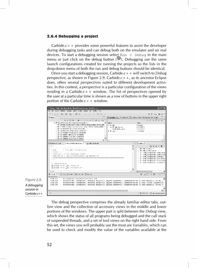
52
2.6.4 Debugging a project
Carbide.c++ provides some powerful features to assist the developer during debugging tasks and can debug both on the emulator and on real devices. To start a debugging session select Run > Debug in the main menu or just click on the debug button ( ). Debugging use the same launch confi gurations created for running the projects so the lists in the drop-down menu of both the run and debug buttons should be identical.
Once you start a debugging session, Carbide.c++ will switch to Debug perspective, as shown in Figure 2.9. Carbide.c++, as its ancestor Eclipse does, offers several perspectives suited to different development activi-ties. In this context, a perspective is a particular confi guration of the views residing in a Carbide.c++ window. The list of perspectives opened by the user at a particular time is shown as a row of buttons in the upper right portion of the Carbide.c++ window.
The debug perspective comprises the already familiar editor tabs, out-line view and the collection of accessory views in the middle and lower portions of the windows. The upper part is split between the Debug view, which shows the status of all programs being debugged and the call stack of suspended threads, and a set of tool views on the right hand side. From this set, the views you will probably use the most are Variables, which can be used to check and modify the value of the variables available at the
Figure 2.9. A debugging session in Carbide.c++

53
current scope, and Breakpoints, which shows the list of breakpoints set by the user. The Breakpoints tab also supports such actions as disabling temporarily all breakpoints, loading and saving them to a fi le and setting watchpoints among other operations.
Watchpoints are a very useful tool to aid debugging which work par-ticularly well to track down memory corruption errors. A watchpoint is similar to a breakpoint in the sense that it stops the execution of the pro-gram at a certain point but, instead of doing so when reaching a specifi c line of code, a watchpoint halts it when a particular variable is accessed. To add a watchpoint, you can either click on Add Watchpoint (C/C++)... in the context menu of any row of the Variables view or select the same option in the context menu of the Breakpoints view and enter the expression to watch yourself.
In addition, Carbide.c++ offers the usual stepping mechanisms expected from a debugger, including suspending and resuming threads and processes. These functions can be easily accessed by using the row of buttons at the top of the Debug view.
Carbide.c++ also supports debugging directly on the device, which is of great importance as sometimes there could be subtle differences between the behavior of the application on the emulator and the phone. To start a debugging session just follow the same instructions for running as on the device presented in the previous section but selecting Debug As from the menu. If you already created a launch confi guration for run-ning on the device you can reuse it for debugging.

54

55
Types, classes and Symbian conventions
This chapter deals with types and classes in the Symbian core and Sym-bian applications. We show the different built-in types and classes for managing basic data, from integers to strings, and the naming conven-tions used through the code to declare the intended use of classes and its elements.
3.1 Naming conventions
Symbian types and classes follow a set of naming conventions. These conventions help to identify the kind of class and the way it is meant to be used. There are other naming conventions that apply to class mem-bers, arguments and other elements as well. While these conventions are not mandatory, application developers are encouraged to follow them to enhance the cohesion with system classes and ease the collaboration between developers.
3.1.1 Class naming conventions
There are four kinds of classes, each one having a different prefi x (T, C, R or M). In addition, static classes do not have a prefi x. However, there are some classes in the operating system that deviate from these conventions. One example of this is HBufC, which is explained in section 3.3.3.
T classesT classes are basic types and value classes, or pointers and references to
data they do not own. These classes (and their data members) must have no destructor. T classes are usually containers of simple data, although they can have a complex interface.
Examples of T classes are Symbian built-in basic types (e.g. TInt, TReal, pointers (e.g. TAny*), structures (e.g. TRectangle) and enu-merations (e.g. TColor). Enumerations should be declared inside classes, to avoid polluting the global namespace. Members of an enumeration are prefi xed with an E, e.g. TColor::ERed.
3

56
typedef int TInteger;
typedef struct { TInteger iX, iY;} TPoint;
typedef struct { enum TColor {ERed, EBlue, EGreen}; TPoint iA, iB; enum TColor iColor;} TRectangle;
class TComplexInterface {private: TRectangle rect;public: // Default copy operator, no default constructor TComplexInterface(TRectangle aRect); TRectangle GetRect(); void SetRect(TRectangle aRec); void DoSomething(); void DoSomethingElse();};
Most of the time T classes can be copied using the default assignment operators and copy constructors, although they can defi ne their own, or even disallow them. T classes can be used safely both on the stack and on the heap as well. For instance, in listing Listing 3.1. p1 is allocated on the stack, while p2 allocated on the heap. Notice that p2 is allocated using a special form of the new} operator, which is discussed on chapter 4.
TPoint add(TPoint aP1, TPoint aP2) { TPoint p; p.x = aP1.x + aP2.x; p.y = aP1.y + aP2.y; return p;}
int main() { TPoint p1 = {0, 0}; // Allocated on the stack TPoint *p2 = new (ELeave) TPoint(); //
Listing 3.1. Declaration of T classes
Listing 3.2. Usage of T classes

57
Allocated on the heap *p2 = p1; // p2 = {0, 0} p1.x = 5; // p1 = {5, 0} p2->y = 7; // p2 = {0, 7} TPoint p3 = add(p1, *p2); // p3 = {5, 7} delete p2;}
However, T classes allocated on the heap that are pushed onto the cleanup stack� will be freed if a leave happens, but their destructors will not be called. This is the reason for not allowing T classes to own data that needs to be destroyed.
C classesC classes are regular classes that must be allocated on the heap. All C
classes must derive directly or indirectly from CBase, which is a Symbian class. In contrast with T classes, C classes can have destructors, so they can own data they point to or reference. However, C classes must never be declared as members of other classes. Instead, a pointer must be used.
class CClass: public CBase {private: CData *iData; // Pointer to owned CData instance TPoint iPoint; // TPoint declared as a member variablepublic: CClass() { iData = new (ELeave) CData; iPoint = {0, 0}; } virtual ~CClass() { delete iData; // Free instance of CData // No need to free instance of TPoint } void DoSomething();};
Listing 3.3. Declaration of
C classes

58
C classes are always passed by pointer or by reference. Thus, they do not need a copy constructor or copy operator (in fact, they are declared as private in CBase), although they can declare and defi ne them if it is appropriate. The destructor of CBase is virtual, so its subclasses can be properly destroyed through a CBase pointer, as long as all the intermedi-ate subclasses have a virtual destructor as well.
void function(CClass *aC) { aC->DoSomething();}
int main() { CClass *c = new (ELeave) CClass(); function(c); // CClass passed by pointer CBase *c2 = c; // Pointer assignment delete c2; // Destroy CClass through CBase pointer}
The new operator in CBase is overloaded to fi ll with zeros all newly allocated objects. Because they have to be allocated on the heap, the con-struction of C classes can fail, e.g. if there is not enough memory. Symbian classes use a pattern called two-phase construction for their constructors to avoid this problem. See chapter 4 for more information on this pattern.
Shallow copy operations are potentially dangerous. For instance, if CClass of listing 3.5 could be assigned using the default shallow copy oper-ator, the CData member variable would be owned by two objects, which would lead problems when destroying them. This is the reason why CBase declares the copy constructor and operator as private. Deep copy operations may also fail if they have to allocate new memory. In these cases, a new function with an L suffi x (see section 3.1.2) to indicate the possibility of an exception, e.g. CopyL, should be used instead of the assignment operator.
class CClass2: public CBase {public: // Factory function for two-phase constructor pattern static CClass* NewL(); // Deep copy method instead of ‘=’ operator CClass2* CopyL();private: CData *iData; // Two-phase construtor pattern:
Listing 3.4. Usage of C classes
Listing 3.5. Two-phase constructor and copy operator on C classes
59
CClass(); void ConstructL();};
R classesR classes are for managing resources, e.g. sockets, fi les. An object of
an R class is not the resource itself, but rather a handler to a resource that exists somewhere else. For instance, in the server-client architecture used through Symbian (see chapter 7) the server is the owner of the resource, while the client has an R object to use it. R classes do not have a base class like C classes, although a number of Symbian R classes are descendants of RHandleBase.
The lifetime of R objects is usually managed through methods rather than constructors and destructors. First, the object is created with no asso-ciated resource. Then, calling a method on this object will ``open’’ a spe-cifi c resource to use through that object. When that resource is no longer needed, it has to be ``closed’’ by calling another method. The R object is then free again to be used to access another resource. Each R class has its own different interface, but these lifetime management methods have similar names across all of them. The ``open’’ method is usually called Open, Create, Allocate, etc., while the ``close’’ method is Close, Free, Destroy, etc.
Since most R classes are quite simple, the default copy constructor and assignment operator should work fi ne. However, it has to be taken into account whether it makes sense having different copies of the same resource handle. In some cases there can be problems if the ownership of the resource is not clear, e.g. something bad can happen if the resource handle is closed twice, or once a handle is closed the other becomes invalid. In these cases, the default copy constructor and assignment opera-tor should be made private.
R objects can be allocated on the stack, as member variables or on the heap. The cleanup stack has special calls to invoke the appropriate ``close’’ method if needed (see chapter 4).
class RDictionary {public: // Lifetime management methods void Open(enum Language aLanguage); void Close(); // Other interface methods CDefi nition* LookupWord(CWord *aWord); enum Language(EEnglishUK, EEnglishUSA);private:
Listing 3.6. Declaration and use of R
classes

60
// Member data for accessing the resource};
void CompareDefi nitions(CWord *aWord) { CDictionary dict; // No resource associated dict.Open(EEnglishUK); // Open resource CDefi nition* def = dict.LookupWord(aWord); dict.Close(); // Close resource dict.Open(EEnglishUSA); // Open another resource def = dict.LookupWord(aWord); dict.Close(); // Close resource};
M classesM classes are ``mix-in’’ interface classes. They are pure abstract
classes, i.e. they only declare methods but not defi ne them, and they do not declare data members. Multiple inheritance is disallowed in Symbian, except with M classes. A class can inherit from any number of M classes as well as one T, C or R class. M classes must appear last in the inheritance list, following any T, C or R base class.
M classes are used to declare an interface that any class can choose to provide, without forcing these classes to any particular implementation of the interface. M classes are used through Symbian with several purposes, e.g. to implement the observer pattern. For instance, in the following example, there are two M classes used with different purposes. MTextO-bserver follows the observer pattern to notify changes to a text of some kind. MDirty can be used to query whether an object has been modifi ed without being saved, i.e. it is ``dirty’’. CTextFile, which represents a text fi le, uses both classes. Firstly, it inherits from MDirty (after CFile) because it contents can change without being saved. It also allows a single observer to be notifi ed of changes made to the contents of the fi le, hence it has a pointer to an instance of MTextObserver whose methods will be called when appropriate.
// Observer patternclass MTextObserver {public: // Pure abstract interface methods void LineAdded(int aNewLine) = 0;
Listing 3.7. Declaration of M classes

61
void LineDeleted(int aDeletedLine) = 0;};
// “Dirty” interfaceclasse MDirty { // Pure abstract interface method boolean IsDirty() = 0;};
// Implements MDirty interface, inherits from C class fi rstclass CTextFile: public CFile, public MDirty {private: boolean iDirty = false; // Dirty fl ag MTextObserver *iObserver; // Single observerpublic: // Implementation of MDirty interface boolean IsDirty() { return iDirty; } void Save() { // Contents saved, fi le no longer dirty iDirty = false; } void AddLine(const TDesC &aLine, int aPos) { // Contents modifi ed, fi le dirty iDirty = true; // Notify observer of changes iObserver.Lineadded(aPos); }};
3.1.2 Other naming conventions
Besides the previous prefi xes for classes and types, there are other nam-ing conventions that apply to classes, types, methods, functions, member variables, arguments and constants.
Every name is written in “CamelCase”, i.e. every word of a compound name starts with a capital letter, and there is no separation between words. All names start with a capital letter, except variables (whether they are local or member) and the arguments of functions, which start with a non-capital letter.

62
Class members variables are prefi xed with i, and should be private. Local variables have no prefi x.
Function and method arguments are prefi xed with a (never an). If the argument ownership is transferred to the function or method, it should be passed as a pointer. Otherwise it should be passed as a reference.
Setter methods have a single way of being written, with one argument passed by pointer, Getter methods may be written in two different ways: one that returns a reference to the object, and another that passes it back as an argument by reference. See listing 3.8.
class CReallyLongClass: public CBase {private: int iData; // i prefi x for member variables TPoint *iPoint;public: // a prefi x for method argument int ProcessData(int aInteger); // Setter method void SetPoint(const Point *aPoint); // Getter method (return) TPoint& Point(); // Getter method (pass by reference) void GetPoint(Point &aPoint);};
Functions and methods that may leave, i.e. may raise an exception, have an L suffi x. Programmers should use leaving functions carefully, so they are marked clearly using this suffi x. See chapter 4 for more informa-tion on what a leave is and how to use leaving functions and methods properly.
Some functions and methods that return a new object may push it onto the cleanup stack before. They have a C suffi x. Most methods that push an object onto the cleanup stack may leave as well, thus they have a LC suffi x. See chapter 4 for more information on the cleanup stack.
Methods that delete the object upon which they are called have a D suffi x.
Constants start with a K prefi x and their names are written in normal “CamelCase”, not with all-uppercase letters.
const int KFactor = 5; // K prefi x for constant
class CAnother: public CBase {
Listing 3.8. Other naming conventions

63
public: void DangerousL(); // L suffi x for leaving method CData* CreateLC(); // C suffi x for method that pushes // an object onto the cleanup stack // (this may leave too) void FinishD(); // D for method that deletes this};
3.2 Built-in data types
Symbian applications are programmed in C++, in an object-oriented fashion. Besides providing several services and frameworks, Symbian also defi nes several built-in data types that should be used instead of the stand-ard ones. These types offer better performance and portability across Sym-bian devices, but in some cases care must be taken to choose the most appropriate type when there are several options.
3.2.1 Numerical types
TInt and TUInt represent 32-bit signed and unsigned integers respec-tively. If needed, a specifi c bit-size can be chosen by using any of the TIntX and TUIntX classes, for X = 8, 16, 32 and 64, although TInt and TUInt are preferred.TReal32 and TReal64 represent 32– and 64-bit fl oating point num-
bers respectively, although its preferred to use TReal, which is equals to TReal64.
3.2.2 Other types
TBool is used for boolean types. True and false are defi ned as enu-meration values: ETrue and EFalse. However, ETrue should not be used directly to verify values from other types different from TBool, e.g. to check the outcome of a function that returns an integer. This is because C++ treats any non-zero integer as true, so a function returning any-thing but a zero should be regarded as returning true. On the other hand, EFalse can be used safely.
64
TBool Function1();TInt Function2();
if (Function1() == EFalse); // Rightif (Function1() == ETrue); // Wrong: ETrue used with TIntif (Function2() == EFalse); // Rightif (Function2() == ETrue); // Right
TText8 and TText16 are narrow and wide characters of 8– and 16-bits, respectively. TText, which is equals to TText16, should be used preferably.TAny* in Symbian as a pointer to ``anything’’, much like void*
would be used in C++. However, void should still be used instead of TAny when referring to ``nothing’’, e.g. as the return type of a function that returns nothing.
// void used instead of TAny: function returns nothing// TAny* used instead of void*: any pointer can be usedvoid Function(TAny *aPointer);
3.3 Descriptors
Descriptors are Symbian classes used for holding and managing text strings or just raw binary data. These are preferred over standard C++ classes, e.g. std::string, or the char * type which is commonly used in C. The descriptor classes were designed with severe memory con-strains in mind, like the ones that would be found on mobile devices. This comes at a price, as they are generally regarded as being diffi cult to understand and work with.
Descriptors do not rely on a NULL terminating character at the end like C strings. Instead, a descriptors holds the length of its contents, which prevents problems such as buffer overruns, i.e. trying to access a position in the data which is beyond its boundaries. This also allows descriptors to hold binary data, since the NULL character can appear within the contents without being interpreted as the end of the data.
There are several kinds of descriptors, all of them deriving directly or indirectly from TDesC. Each one serves a different purpose, e.g. a kind of descriptor may be used to hold a string on the heap while another may be used to point to an already existing string. There is also support for literal
Listing 3.10 TBool built-in data type
Listing 3.11. TAny built-in data type

65
string, e.g. strings whose content is constant. Literals can be used as if they were descriptors, but they do not inherit from TDesC and are not part of the descriptor hierarchy. Although descriptors classes are organized in a inheritance hierarchy and C++ supports method redefi nition, all the common interface methods are defi ned only in TDesC for performance and memory reasons. These methods take into account the specifi c kind of descriptor on which they are called, which is available as a fi eld in every descriptor object, and act accordingly.
Like some Symbian built-in data types, descriptors come in two dif-ferent versions depending of the width of the characters that they hold. There are versions for 8-bit characters (e.g. TPtr8) and 16-bit characters (e.g. TPtr16). The default versions (without a suffi x) correspond to the 16-bit versions, and should be used when there is no reason to explicitly select a character width. When working with binary data the 8-bit versions should be used to be able to operate at byte level.
Table 3.1. shows the main features of each descriptor class. The main differences between descriptors classes are whether they are modifi able or not, and the location and ownership of their content. All descriptor classes ending with C are not modifi able, e.g. the strings that they represent are read-only. However, we will see that it is still possible to access the con-tents of a non-modifi able descriptor to make changes. Regarding the location of the content itself, some descriptor classes have their contents inside the object itself, like another fi eld, while other descriptor classes serve as pointers to strings that are located somewhere else. In the latter case descriptors may own that pointed data and thus are responsible for creating or destroying the data, or they may act as pointers to data owned by some other object (even another descriptor).
Figure 3.1. Descriptor
hierarchy. The base class for
all descriptors is TDesC,
which is non-modifi able.
TDes and its derived classes are modifi able.
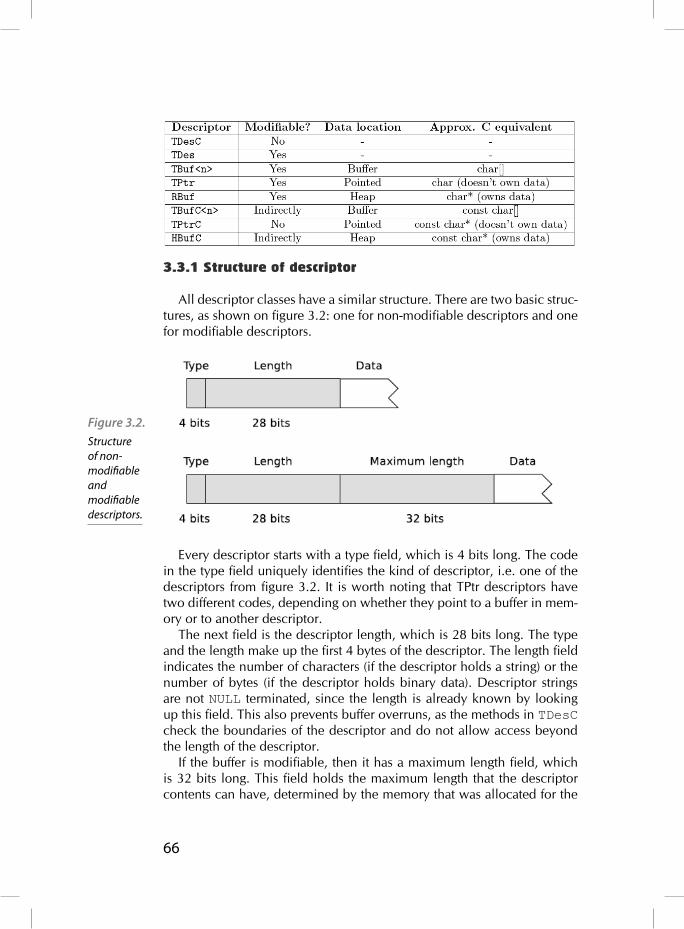
66
3.3.1 Structure of descriptor
All descriptor classes have a similar structure. There are two basic struc-tures, as shown on fi gure 3.2: one for non-modifi able descriptors and one for modifi able descriptors.
Every descriptor starts with a type fi eld, which is 4 bits long. The code in the type fi eld uniquely identifi es the kind of descriptor, i.e. one of the descriptors from fi gure 3.2. It is worth noting that TPtr descriptors have two different codes, depending on whether they point to a buffer in mem-ory or to another descriptor.
The next fi eld is the descriptor length, which is 28 bits long. The type and the length make up the fi rst 4 bytes of the descriptor. The length fi eld indicates the number of characters (if the descriptor holds a string) or the number of bytes (if the descriptor holds binary data). Descriptor strings are not NULL terminated, since the length is already known by looking up this fi eld. This also prevents buffer overruns, as the methods in TDesC check the boundaries of the descriptor and do not allow access beyond the length of the descriptor.
If the buffer is modifi able, then it has a maximum length fi eld, which is 32 bits long. This fi eld holds the maximum length that the descriptor contents can have, determined by the memory that was allocated for the
Figure 3.2. Structure of non-modifi able and modifi able descriptors.

67
contents. This allows descriptor data to be resized within limits, e.g. the current length fi eld cannot be greater than the maximum length fi eld. If a descriptor grows or shrinks because of a call to one of its methods, this fi eld is automatically updated. If the data is accessed directly and its length changed, it is the programmer’s responsibility to update this fi eld.
The last fi eld in a descriptor is the data fi eld, which can either be a buffer that holds the content of the descriptor, or a pointer to the data if it is located elsewhere. In the former the data is said to be owned, it is inseparable from the descriptor. In the latter the data can be either owned or just referenced. The maximum length of a descriptor with a buffer can-not be changed, as it would require a new descriptor to be created with the desired maximum length. The sections on TBuf<n>c, HBufC and RBuf descriptors have some insights on this issue and possible solutions. On the other hand, pointer classes have an easier way to change their maximum length without creating a new descriptor.
3.3.2 Useful methods
One of the advantages of descriptors is that they come with a full range of methods, to perform tasks from string comparison to formatting. Before we dive into the specifi cs of each kind of descriptor, we will see some of these methods.
These methods can be divided into two categories: methods that do not modify data and methods that do. The former are available to all descriptors as they are declared on the base class of all descriptors, TDesC. However, the latter are only available for modifi able descriptors, i.e. those that inherit from TDes. Some of the methods belonging to the fi rst category are:
[]: Index operator. Length: Length of the descriptor in characters. Size: Size of a descriptor in bytes. Left, Right, Mid: Extract the leftmost, rightmost or middle part, respectively. Compare, CompareC, CompareF: Compare two strings. Find, FindC, FindF: Search for a substring inside the descriptor. Match, MatchC, MatchF: Search for a pattern. Locate: Search for a single character. AllocL (HBufC only): Create a new HBufC with a copy of the con-tents of the descriptor.
Beware of the distinction between Length() and Size(). The former should be used when dealing with descriptors containing text strings, while the latter should be used for descriptors containing binary

68
data. Note that both methods would return the same number on a 8-bit descriptor (like TPtr8), but this is not recommended.
Several of the methods discussed above, e.g. Compare or Find, involve comparing two strings or matching a string in a descriptor. Sym-bian offers three versions of each of these methods taking into account different ways of comparing strings, letting the programmer decide which one is more suitable in each context. These versions are distinguished by their suffi x, which can be either C (as in collation), F (as in folding) or no suffi x. The no suffi x version performs a binary comparison, which is useful if the descriptors being compared hold binary data. The version with a C suffi x performs a collation comparison, which takes into account cultural and regional differences according to locale. This version is suitable for comparing natural language strings. The version with a F suffi x performs a folding comparison. This is similar to the collation version, but addition-ally the text is normalized in order to ignore case distinction, accents, etc., i.e. it is a locale-independent comparison.
// Assume the following non-modifi able descriptorsTDesC desc1 = ...; // “María”TDesC desc2 = ...; // “Maria”
desc1[2] // ‘a’
TPtrC ptrc1 = desc1.Left(3); // “Mar”TPtrC ptrc2 = desc1.Right(2); // “ía”TPtrC ptrc3 = desc1.Mid(2, 2); // “rí”
desc1.Locate(‘a’); // 1, offset of fi rst ‘a’desc1.Locate(‘x’) // returns KErrNotFound
desc1.Compare(desc2); // != 0, not equalsdesc1.CompareC(desc2); // != 0desc1.CompareF(desc2); // 0, equals
_LIT(KStr1, “Mar”); // Constant strings,_LIT(KStr2, “mar”); // see section on literals_LIT(KStr3, “ar?a”);
desc1.Find(KStr1); // 0, position of matchdesc1.Find(KStr2); // KErrNotFound
Listing 3.12 Read-only methods of descriptors.

69
desc2.Find(KStr2); // 0desc1.Match(Kstr3); // 1desc2.Match(Kstr3); // 1
These are some of the methods that modify the contents and/or length of a descriptor:
MaxLength: Maxiumum length of the descriptor in characters. Append: Append a character or descriptor. Insert: Insert descriptor at position. Delete: Delete a substring. Replace: Replace a substring with a descriptor. Trim: Remove leading and trailing withespace. Lowercase, Uppercase: Convert to lowercase/uppercase. Num , NumC: Copy a decimal value as a string. Format: sprintf-like formatting.
// Assume the following modifi able descriptor// with enough maximum lengthTDes des1 = ...; // “Hello”TDes des2 = ...; // “World”TDes des3 = ...; // “ “TDes des4 = ...; // “Symbian”
des1.Append(des2); // “HelloWorld”des1.Insert(5, des3); // “Hello World”des1.Replace(6, 5, des4); // “Hello Symbian”des1.Lowercase(); // “hello symbian”
des1.Format(“ %s example #%d “, des4, 128); // “ Symbian example #128 “des1.Trim(); // “Symbian example #128”
3.3.3 Descriptor classes
This section discusses each of the descriptors classes outlined previously.
Literal descriptorsLiteral descriptors are strings whose contents are constant. The class
that represents literal descriptors is TLitC, although they are always
Listing 3.13. Read-only
methods of descriptors.
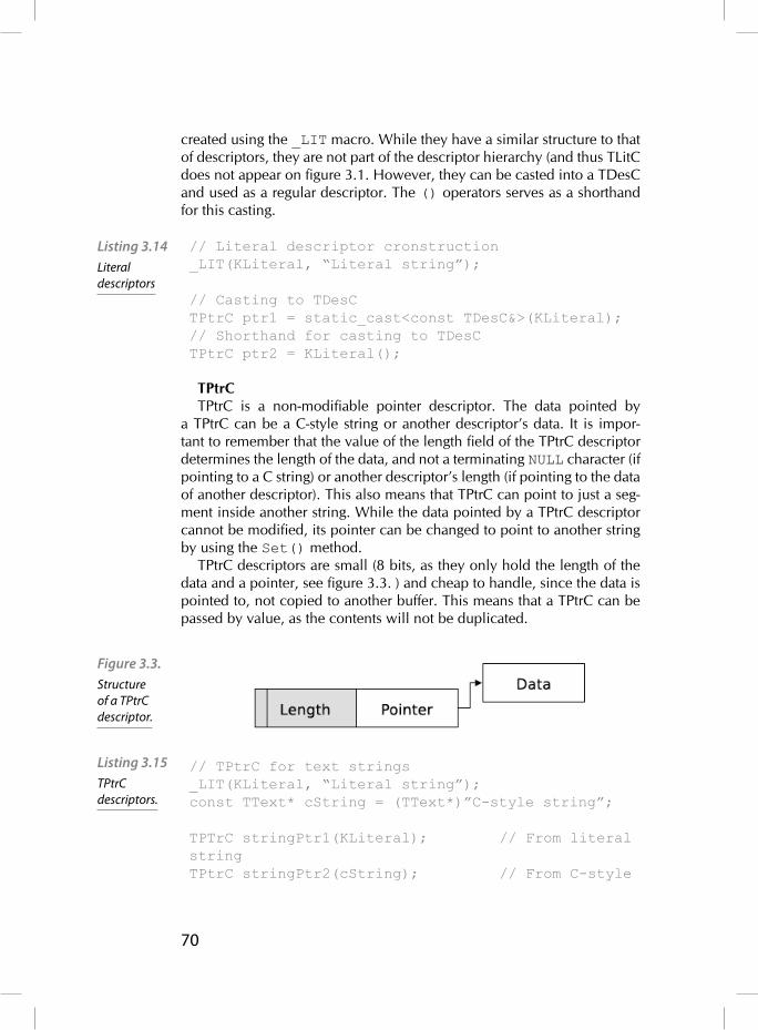
70
created using the _LIT macro. While they have a similar structure to that of descriptors, they are not part of the descriptor hierarchy (and thus TLitC does not appear on fi gure 3.1. However, they can be casted into a TDesC and used as a regular descriptor. The () operators serves as a shorthand for this casting.
// Literal descriptor cronstruction_LIT(KLiteral, “Literal string”);
// Casting to TDesCTPtrC ptr1 = static_cast<const TDesC&>(KLiteral);// Shorthand for casting to TDesCTPtrC ptr2 = KLiteral();
TPtrCTPtrC is a non-modifi able pointer descriptor. The data pointed by
a TPtrC can be a C-style string or another descriptor’s data. It is impor-tant to remember that the value of the length fi eld of the TPtrC descriptor determines the length of the data, and not a terminating NULL character (if pointing to a C string) or another descriptor’s length (if pointing to the data of another descriptor). This also means that TPtrC can point to just a seg-ment inside another string. While the data pointed by a TPtrC descriptor cannot be modifi ed, its pointer can be changed to point to another string by using the Set() method.
TPtrC descriptors are small (8 bits, as they only hold the length of the data and a pointer, see fi gure 3.3. ) and cheap to handle, since the data is pointed to, not copied to another buffer. This means that a TPtrC can be passed by value, as the contents will not be duplicated.
// TPtrC for text strings_LIT(KLiteral, “Literal string”);const TText* cString = (TText*)”C-style string”;
TPTrC stringPtr1(KLiteral); // From literal stringTPtrC stringPtr2(cString); // From C-style
Listing 3.14 Literal descriptors
Figure 3.3. Structure of a TPtrC descriptor.
Listing 3.15 TPtrC descriptors.

71
stringTPtrC stringPtr3(cString, cString+3); // Fragment “C-s”TPTrC stringPtr4(ptr1); // Copy constructor, both // point to the same data
// TPtrC for raw binary dataTUint8* mem = ...; // Some memory locationTInt length = ...; // Memory location lengthTPtrC8 memPtr(mem, length);
TPtrTPtr is a modifi able pointer descriptor. The structure of a TPtr descriptor
can be seen on fi gure 3.4. Like TPtrC, a TPtr descriptor points to a string in memory, like a C-like string or another descriptor’s data. Similarly to TPtrC, the pointer of the descriptor can be changed by calling Set().
The behavior of the copy constructor and assignment operator can be confusing at fi rst. The copy constructor creates a new TPtr descriptor which points to the same data, i.e. the data itself is not copied. How-ever, the assignment operator does copy the data from one descriptor into another.
There is a variant of TPtr which instead of pointing to a string in mem-ory, it points to a whole descriptor. This variant has a different type value, although it is still regarded as a TPtr. A TPtr of this kind is obtained by call-ing Des() on a HBufC or a TBufC descriptor, and is used to change the contents of these otherwise constant buffers (both HBufC and TBufC are non-modifi able). Both descriptors are linked, so changing the length on the TPtr descriptor will also change it on the pointed descriptor. Because of this special link, no more than one TPtr for the same descriptor should be used at a time. Although the Des() method is useful to modify other-wise constant descriptors, it is a expensive method, so it should be used judiciously.
Figure 3.4. Structure of a TPtr
descriptor when pointing
to a memory buff er.

72
// TPtr constructionTText mem[20];_LIT(KLiteral, “Literal string”);HBufC<20> buf(KLiteral);TPtr ptr1(mem, 20); // Length = 0, max = 20TPtr ptr2(mem, 10, 20); // Length = 10, max = 20TPtr ptr3(buf.Des()); // Length = 14, max = 20
// Beware of copy constructor, assignment operatorTPtr ptr4 = ptr1; // ptr4 points to mem bufferptr4 = ptr3; // Copies buf content into mem
// Error in assignmentTPtr ptr5(mem, 5); // Length = 0, max = 5ptr5 = ptr3; // Panic: max length (5) exceeded (14)
TbufC<n>TbufC<n> is a non-modifi able buffer descriptor. The structure of
a TbufC<n> can be seen on fi gure 3.6. The length of the descriptor is given by the template parameter n, so it must be used for strings whose length is known in compile time. A TbufC<n> descriptor thus cannot be used to copy an arbitrary length descriptor, as the length cannot be set at runtime depending on the length of the other descriptor. TbufC<n> descriptors are usually declared on the stack or as a data member in other objects for fi xed size or small strings.
Figure 3.5. Structure of a TPtr descriptor when pointing to another descriptor.
Listing 3.16. TPtr descriptors
Figure 3.6. Structure of a TbufC<n> descriptor.

73
TbufC<n> copy constructor copies the data it receives into the new descriptor, as does the assignment operator. Although TbufC<n> is non-modifi able directly, a TPtr pointing to a TbufC<n> can be obtained by calling Des(), as explained in the section on TPtr descriptors. This new TPtr descriptor is linked to the original TbufC<n> descriptor and makes the contents of the descriptor modifi able.
// TBufC<n> construction_LIT(KLiteral, “Literal string”);TBufC<15> buf1(KLiteral); // Copies KLiteral dataTBufC<15> buf2(buf1); // Copies buf2 dataTBufC<20> buf3((TText*) “A C-style string”);TBufC<20> buf4; // Empty, lenth = 0
// Assignment operatorbuf1 = buf3; // buf3 data copied into buf1, length changedbuf3 = buf1; // Panic: max length (15) exceeded (16)
// Des() methodTPtr ptr(buf1.Des()); // Data is in buf1, max length = 15ptr = (TText*)”Text”; // Replaces string in buf1, // ptr.Length() == buf1.Length() == 4
TBuf<n>TBuf<n> is a modifi able buffer descriptor. The structure of a TBuf<n>
can be seen on fi gure 3.7. It is similar to TBufC<n>, but its contents can be modifi ed and its length changed up to the maximum length specifi ed in the template parameter n. However, TBuf<n> does not provide meth-ods for reallocation, i.e. its maximum length must be known at compile time and cannot change. If this is important, both HBufC and RBuf allow reallocation. Just like TbufC, TBuf<n> descriptors cannot be used to copy arbitrary length strings.
Listing 3.17. TbufC<n>
descriptors

74
// TBuf<n> construction_LIT(KLiteral, “Literal string”);
TBuf<15> buf1(KLiteral); // Copies KLiteral dataTBuf<15> buf2(buf1); // Copies buf2 dataTBuf<20> buf3((TText*) “A C-style string”);
// Assignment operatorbuf1 = buf3; // buf3 data copied into buf1, length changedbuf3 = buf1; // Panic: max length (15) exceeded (16)
HBufC HBufC is a non-modifi able heap-based descriptor. The structure of
a HBufC can be seen on fi gure 3.8. Being heap-based means that it must be allocated on the heap. Thus, these descriptors are always used as a pointer, i.e. HBufC*. HBufC descriptors must be created with one of the NewL() statics methods. Additionally, any descriptor can be copied into a new HBufC using Alloc() or AllocL().
Unlike TbufC, the length of a HBufC can be set at runtime. The current length of the descriptor is stored in the length fi eld, as can be seen on fi gure 3.8. The maximum length of the descriptor is the size of the heap cell on which the descriptor was allocated. The contents of the descrip-tor can be modifi ed using the assignment operator, which copies the descriptor data into the buffer. The assignment operator be used with lit-eral descriptors as well. The contents can also be modifi ed through a TPtr obtained calling Des(), as explained in the section on TPtr descriptors. However, if the length of the contents after being modifi ed is bigger than the maximum length, the descriptor has to be reallocated manually fi rst to a new heap cell using ReAllocL(). This usually means that the existing pointers to the descriptors will be invalidated, because the descriptor has moved to a new heap cell with a different memory address. This problem can be eased using a RBuf descriptor, described on the next section.
Listing 3.18. TBuf<n> descriptors
Figure 3.7. Structure of a TBuf<n> descriptor.
Figure 3.8. Structure of a HBufC descriptor.

75
// HBufC construction_LIT(KLiteral1, “Literal string”);TBuf<15> tbuf(KLiteral1);HBufC* buf1(KLiteral1); // Copies KLiteral dataHBufC* buf2 = HBufC::NewLC(20); // Empty, max length = 20buf2 = tbuf; // Copies tbuf data, length = 14HBufC* buf3 = tbuf.AllocL(); // New copy of tbuf data
// Reallocating a HBufC_LIT(KLiteral2, “Another literal string”);buf2 = buf2->ReAllocL(25); // Reallocate to increase // max lengthCleanupStack::Pop(); // Pop the original buf2CleanupStack::PushL(buf2); // Push the new buf2*buf2 = KLiteral2; // Direct copy of KLiteral2
RBufRBuf is a modifi able heap-based buffer descriptor. Similarly to TPtr, it
can point to a buffer or to an HBufC descriptor. The structure of a RBuf can be seen on fi gure 3.9. RBuf can be seen as a combination os a TPtr modifi able pointer with an HBufC heap-based buffer. Unlike a HBufC, the descriptor itself can be declared on the stack.
Listing 3.19. HBufC
descriptors
Figure 3.9. Structure of a RBuf
descriptor.

76
When a RBuf is created with an HBufC, RBuf takes ownership of this descriptor and uses it as a buffer. If no HBufC is given, RBuf will be ini-tialized empty and with no memory buffer. This buffer can be allocated by calling CreateL() with a given maximum length. The Close() method frees this buffer (but does not delete the descriptor itself), as with regular resource classes (see section on R classes).
The maximum length of a RBuf can changed, which requires that the underlying heap buffer be reallocated manually. However, since the heap buffer is internal and only accessed through a RBuf pointer, references to this descriptor are still valid after reallocation. This is a signifi cant advan-tage of RBuf over other descriptor classes. Thus, RBuf is recommended for heap-allocated data that changes frequently, as the pointers to it do not have to be updated after each reallocation.
// RBuf construction_LIT(KLiteral1, “Literal string”);RBuf rbuf1; // Empty RBuf, zero lengthrbuf1.Create(20); // Create buffer for rbuf1, length 20rbuf1 = KLiteral1; // Copies KLiteral data, length = 14HBufC hbuf = HBufC::NewL(20);RBuf rbuf2(hbuf); // Take ownership and use as heap buffer
// RBuf reallocation_LIT(KLiteral2, “, plus more”);rbuf1.CleanupClosePushL(); // Push onto the cleanup stack// Allocate enough space for appending another stringrbuf1.ReAllocL(rbuf1.Length() + KLiteral2.Length());rbuf1.Append(KLiteral2()); // rbuf1 pointer is still valid
Listing 3.20. RBuf descriptors

77
Memory management
In this section, the memory management of the Symbian operating sys-tem will be addressed. Memory management has been the focal point of the Symbian OS. This system is designed for mobile devices that have lim-ited resources, i.e. memory, processor speed, battery capacity, and oper-ate without interruption for a very long time – i.e. they are not rebooted. This particularly affects the accumulation of memory leaks. While in the case of PC computer, memory shortages are not a critical issue, in the case of mobile devices, they are. Personal computers are quite often turned off and on – on this occasion, memory leaks are removed. When the system is not rebooted for a long time memory leaks cumulate and at one point, it appears that,although no application is being run, the system informs of out-of-memory situation. This is the result of lost pointers to allocated memory blocks, which should be freed on the grounds of error. This is particularly true in the case of exceptions or errors not expected by the programmer. Especially applications designed to work over the years (Ker-nel, Servers, Calendar, and Contacts) must be durable. Mechanisms and tools made by the designers of Symbian OS are intended to eliminate the formation of memory leaks. Special tools are used to test readiness of the application to address memory management issues. These tools generate exceptions and errors in the system (such as memory allocation error) so that later it is possible to observe the behavior of application and whether or not it freed the allocated memory. Additionally, special macros are provided to help programmers write clean applications: it is possible to check the heap before and after the section of code. Failure to comply with the principles of memory management ends in system errors (pan-ics), and consequently the accumulation of leaks and the need to reboot the device.
Memory is managed by the MMU (Memory Management Unit). Read only memory (ROM) is organized in fi les in the structure of a logical drive: the fi les are mapped directly to fi xed addresses in the ROM memory, so reading operation is simple – the contents of the fi le are directly read from the specifi ed address in the proper order. By contrast, handling of RAM is more complicated. It is divided into 4K pages each. Each page can be allocated to a different purpose:
virtual address space of processes, kernel, DLL, RAM disk,
4

78
translation tables (MMU) for virtual address space of processes, a free pages list.
Sample allocation of memory pages is illustrated in fi gure below:
What is important is that Symbian OS has no virtual memory, which on personal computers is typically organized as a fi le exchange (swap) on the disk. Therefore, if there is no free page in the list of available pages (free list) the out-of-memory error occurs and that exceptional situation must be handled.
Of course, most of the pages will be allocated for processes (virtual address space).The following fi gure shows schematically the virtual address space for three processes.
Process A
Process B
C: RAM drive
Kernel
Free list
DLL
Video RAM MMU Tables
Figure 1 Memory pages and their sample allocation

79
Each process in its address space has access to the system ROM and the DLLs that are loaded into RAM (they occur at the same address in virtual address space for all processes and are only available in read-only mode). In the address space of each process there is a process image (loaded from .exe fi le), a default stack and a heap for a default thread. In addition, when a programmer creates a new thread in the current process space is also allocated for the new stack and heap of this thread. A programmer can create additional heap manually and it can be shared among the threads within a process (local shared heap), or among processes (global shared heap). However, in the case of a shared heap it is necessary to apply the usual methods of synchronization of accesses to shared resources (sema-phores, mutexes, etc.).
4.1 Stack and heap
In this section we will discuss differences in using a stack and a heap for storing objects.
Process CProcess BProcess A
ROM
DLLs loaded to RAM
0
Virt
ual A
ddre
ss S
pace
Global shared heap X
Local shared heap
Thread 2 Heap
Thread 1 Heap
Thread 2 Stack
Thread 1 Stack
ProcA.exe image ProcB.exe image
Thread 1 Stack
Thread 1 Heap
Global shared heap Y
Global shared heap X
Global shared heap Y
Thread 1 Heap
Thread 1 Stack
ProcC.exe image
Figure 2 The structure
of memory with 3
processes

80
Stack: automatic memory allocation and release Heap: allocations and explicit release by the programmer. Pointers from the stack point to objects on the heap
TInt i;TDateTime time;
Variable i and time are created on the stack. The programmer does not need to remember about their removal. Automatic variables are very convenient, but the stack has very limited capacity (typically 12kB), so the programmer must be careful not to overfl ow the stack. Therefore, larger objects are created on the heap and in this case only pointers to the cre-ated objects are stored on the stack. This rule applies to all classes of prefi x C – they should be created on the heap. T classes are usually small so they can be handled automatically on the stack.
CClass * c = new (ELeave) CClass;
c CClass
HeapStack
For the newly created process there is a single thread spawned with the default stack and heap. Stack size (typically 12kB) can be controlled by the parameters of the executable fi le (.exe) or when the thread is explicitly created from within the running process. When a thread is created, the size of the stack can no longer be changed (for example, it can not be extended if necessary). On the other hand, the heap is fl exible and can grow up to the exhaustion of all available memory in the system. Extend-ing the heap leads to the allocation of another page of memory controlled by the MMU. When there is no available free page the out-of-memory error occurs.
Each heap can grow up to the exhaustion of system memory so it is important to remove unnecessary objects from the heap as soon as pos-sible so that there is no situation that objects are not removed at all.
4.2 Cleanup Stack
The Cleanup Stack is a special purpose stack. It is used to store those pointers which are the only references to created objects. The typical situ-ation is when a pointer is declared within the function (as an automatic
Figure 3 Automatic variable c from the stack is a pointer to an object class CClass located on the heap.

81
variable stored on the stack) and the function may suffer exception. If an exception occurs inside a function which allocates a reference in the local variable to some object and stores – the reference to this object is lost – it is not possible to free the memory occupied by the object. Symbian does not use the exception mechanism of C++ – system; designers, there-fore, provided support for such emergencies so that no memory leaks take place.
It is the best to follow the sample code fragment below:
(1) CA * a = new (ELeave) CA;(2) a->CalculateL();(3) delete a;
First, an object of class CA is created using overloaded new(ELeave) operator, which may cause an exception due to out-of-memory error. A pointer to the newly created object is stored on the stack as a local vari-able a (1). Then CalculateL() method of CA class is called (2). In the end, the object is deleted and the memory freed using the delete operator (3).
If an exception is thrown in (1) due to the lack of memory, the whole piece of code (1-3) will be safely abandoned. If, however, an exception appears in (2) – method CalculateL() may generate an exception (suffi x L) – the line (3) will be omitted and the created object is not removed. The variable a will be removed from the stack automatically as a local vari-able and we will permanently lose the reference to the created object of class CA – memory leak appears. Those leaks are detected by the system later, when the entire application is closed or when the application is used inside a macro to check the status of the heap. When the system detects a leak, the application will immediately be closed and will generate panic (see Panics). Nevertheless, the memory is lost and cannot be easily recov-ered until the system is rebooted.
The solution to such problems is the Cleanup Stack – a stack on which we store pointers which could be lost in case of any exception. Let’s have a look at what our piece of code looks like while using the Cleanup Stack:
(1) CA * a = new (ELeave) CA;(2) CleanupStack::PushL(a);(3) a->CalculateL();(4) CleanupStack::PopAndDestroy(a);
As we can see, the only difference is in the line (2): a pointer is stored at Cleanup Stack and when it is no longer required it is removed from the Cleanup Stack (4). This way we create a closing brace of the code in which exceptions may arise from e.g. out-of-memory situations. When no
82
exception occurs in (3) the pointer is simply removed from the Cleanup Stack (4). When an exception occurs (3) then the Symbian OS guarantees that all objects referenced by pointers stored on the CleanupStack will be deleted and memory released – it is a part of the exception handling procedure.
Along with the method CleanupStack::PopAndDestroy(a) there is also defi ned CleanupStack::Pop() which only removes a pointer from the cleanup stack but does not delete it.
There are several rules when using the CleanupStack. Namely, we should remember that we do not put on CleanupStack those pointers which are stored as class members. Member objects are deleted in the class destructor – putting them further on the Cleanup Stack would result in trying to delete them again and consequently will lead to an error. Therefore, the convention requires that the variable member objects use the prefi x “i” e.g. iMemberObject. With such a convention it is easy to detect an attempt of putting a member variable on the CleanupStack.
If an exception occurs:
PopAndDestroy() extracts a pointer from the CleanupStack and calls its destructor
PopAnDestroy() is atomic Pointers must be removed from the CleanupStack if the danger of losing them passes
4.3 Two-phase constructor
In the Symbian OS, we cannot directly use the C++ constructors. Why? They are not safe when it comes to memory management. And exactly the point is that in C++ constructors we cannot afford an excep-tion. If the exception appears this may lead to memory leak. Let’s look at this further.
CA * a = new (Eleave) CA;
is equivalent to:
(1) CA * a;(2) CA * tmp = User::AllocL(sizeof(CA)); // memory allocation for object(3) tmp->CA::CA(); // call the constructor and build all components(4) a = tmp;

83
As you can see, the critical point lies between (2) and (3). After allocat-ing memory for an object, the pointer to the CA object is stored in the tmp local variable, which in case of an exception in the constructor (3) is lost. Memory leak occurs. Therefore, in the Symbian OS another approach to object construction is introduced – a two-phase constructor.
In general, objects are constructed in 2 phases when an exception can occur while creation. In the fi rst phase normal C++ constructor is exe-cuted. It must not contain code that can cause an exception. In phase 2 the object components are created. In the second phase exceptions can occur and are handled correctly. The convention is that the second phase construction method is called ConstructL().
To facilitate the operations of two-phase constructions the conven-ience static method NewL() has been introduced, which performs two phases of construction together. This is a type of factory method that returns a pointer to the newly created object initialized fully with all com-ponents. As its name implies, this method can cause an exception (suffi x L). To assure the proper usage of construction typically the C++ construc-tor of the class is private – so it is not called from outside the class. Instead, the method NewL() calls the constructor directly and then composes the object by calling ConstructL();
Because the method NewL() is static, you can call it without having an instance of an object.
Let’s look at the example with the declaration of the class CObject.
Class CObject: public CBase{ public: static CObject * NewL(TInt anInt, CBase * aObj); void ConstructL (CBase * aObj); private: CObject(TInt aValue); private: Tint iInt; COne * iOne; CTwo * iTwo;};
In the fi rst phase the private constructor is called – the instance is cre-ated and stored in the variable self. To avoid losing the reference to the newly created object the pointer is saved to the CleanupStack. Then, it can be called that part of construction which can generate exceptions ConstructL():

84
CObject * CObject::NewL(TInt anInt, CBase * aObj){ CObject * self = new (ELeave) CObject(anInt); CleanupStack::PushL(self); self->ConstructL(aObj); CleanupStack::Pop(self); return self;} CObject::CObject(TInt aInt):iInt(aInt){ // some other code}
In C++ constructor, we initiate only the fi elds that do not require allo-cation on the heap.
In the second phase the object components (denoted by the prefi x i) are constructed. They can be created with the method NewL() when objects are complex or a standard C++ constructor if they cannot generate an exception during construction:
void CObject::ConstructL(CBase * aObj){ iOne = new(ELeave)COne(); iTwo = CTwo::NewL(aObj);}
The destructor deletes the object class components (prefi x i).
CObject::~CObject(){ delete iOne; delete iTwo;}
4.3.1 NewLC() and NewL()
The convention of factory functions for C classes is demonstrated on the following example:
CObject * CObject::NewLC(Tint aInt, CBase * aObj){

85
CObject * self = new (ELeave) CObject(aInt); CleanupStack::PushL(self); self->ConstructL(aObj); return self;}
CObject * CObject::NewL(TInt aInt, CBase * aObj){ CObject * self = NewLC(aInt, aObj); CleanupStack::Pop(); return self;}
4.4 Rules for handling memory for objects of different types of classes
This paragraph summarizes the conventions and rules that should be followed to fulfi l the Symbian OS application memory management requirements.
Notes to create constructors and destructors (Conventions) private default C++ constructor CBase constructor zeros out the data BaseConstructL nomenclature for abstract classes and ConstructL for derived classes
do not put pointer to the object members to CleanupStack CBase virtual destructor is always called while exception handling Do not delete the objects that are not owned by the class Do not delete the objects twice reset pointers on their re-use destructors cannot generate exceptions do not assume that the object was fully constructed in the constructor.
4.4.1 Constructors in abstract classes
This section focuses on the specifi c conventions applied to construction of the abstract classes (with pure virtual methods only).
The convention is as follows: the name of the two-phase constructor abstract class is BaseConstructL()
The example below shows this rule:
CObject: public CBaseObjectCBaseObject::BaseConstructL() {}

86
void CObject::ConstructL() { BaseConstructL(); // continued construction of CObject}
4.5 Classes other than CBase
4.5.1 Class C and T
The overloaded PushL() methods allow us to put objects other than inherited from CBase on the CleanupStack:
static void PushL (Tany * aPtr);static void PushL (CBase * aPtr);static void PushL (TCleanupItem anItem);TAny – we can put all T types on the Cleanup Stack.
T classes, in contrast to the C classes, do not need a destructor because they do not allocate memory for data. Typically, the T classes are: defi ned types, enumerations, simple structures etc. They may contain a pointer, such as TPtrC class, but they are not the owner of the pointed object; instead they indicate just the use of it. Therefore, the T classes are usu-ally allocated on the stack or are components of the other classes. They can also be placed on the heap if necessary; then the overloaded method PushL (TAny * aPtr) is used. In this case when we call the PopAndDe-stroy() method, the object pointer is removed from the heap and memory is released, but destructor is not called. Let’s look at the sample below:
(1) TText * buf = (TText *) User::Alloc(1000*sizeof(TText));(2)CleanupStack::PushL(buf);//code that may leave(3)CleanupStack::PopAndDestroy();
The buf variable is a pointer to a buffer (1). Because the allocation of the buffer could lead to memory leak if an exception occurs, then it is pushed to the CleanupStack (2). When it cannot be lost any more it is popped from the CleanupStack (3).
It is also possible to create your own TCleanupItem classes that support unusual ways to use the Cleanup -– this class is a wrapper and all PushL() method implementations actually create the appropriate TCleanupItem.

87
4.5.2 R-Class
Typically, the CleanupStack is made use of when C classes are used. However, also the R classes (resource) are related to memory manage-ment issues. Typically, in these classes there is a handle to the resources managed in a different process (e.g. FileServer, WindowServer, kernel). R objects are usually rather small. Therefore, R classes, similarly to T classes, can be created on the stack (automatic variables) or directly as compo-nents of other classes. R class objects are passed by value or by reference – it is not common to use passing by pointer.
R-Class is typically associated with managed resources in another place. Available operations are usually like Open() and Close(), which correspond to constructors and destructors of typical C classes. Therefore, if the R classes are components of C classes (typical), the destructor of C class will contain a method Close() of the corresponding component of R class. The corresponding function Open() may be located in the Con-structL () of C class.
The example below shows how to handle R classes when used as auto-matic variables and pushed to CleanupStack (excerpt from the chapter summary application Example 3).
case ECommand11: { RFS fs; CleanupClosePushL(fs); User::LeaveIfError(fs.Connect()); RFileReadStream reader; reader.PushL(); User::LeaveIfError(reader.Open(fs, KFileName, EFileRead)); HBufC * text = HBufC::NewLC(reader, 32); iAppView->Print(*text); CleanupStack::PopAndDestroy(3); // text, reader, fs }
The key in this example is to use a method CleanClosePushL(fs). It actu-ally creates TCleanupItem and when this item is popped from the Clean-upStack by PopAndDestroy(), the method Close() of this item is called instead of its destructor. Methods CleanupReleasePushL() and Cleanup-DeletePushL() work in a similar way, which differ only in the end; instead of the destructor, the methods Release() or Delete() are called, respectively.

88
4.3.5 Demand paging
Symbian has implemented the demand paging memory management technique to reduce the time required to load application and to optimize RAM memory usage. Demand paging has been implemented in recent versions of the Symbian OS that is 9.3, 9.4 and 9.5
Paging on demand allows the programmer to use RAM more effi ciently by loading code and read-only data only when required (on demand).
Data must be copied from Flash memory into RAM in order to execute Previously, entire Symbian OS DLLs were copied into RAM when they were needed
Demand paging means that only the required «page» within the DLL is loaded into RAM
Demand paging only loads a page into RAM when a reference is made to it (on demand paging)
Loading that page means less RAM is used
DLL 3
DLL 1
DLL 2
DLL 4
DLL 5
C: ramdisk
Free Memory
DLL 2,2
DLL 5,1
DLL 1,3
DLL 4,1
DLL 4,4
DLL 3,1
DLL 1,1
CODE
RAM
Flash + ROM
Memory page
Figure 4 Demand paging. Only needed pages of the DLL code stored in ROM and Flash are loaded to RAM.

89
Demand Paging is a more effi cient way of loading data into RAM:
The code that does not need to be executed is not loaded into RAM ROMFS contains the whole image The core image is an interleaved subset Pages from DLLs are copied into RAM Idle code pages are automatically unloaded RAM only used by code executing
Benefi ts of Demand Paging
Lower RAM usage: requires less code to be loaded into RAM at any moment
System and Application start-up improvement: not whole application needs to be loaded into RAM before execution can start; especially visible for large applications like Browser or Messaging.
Stability: less frequent out-of-memory situations, applications closing not necessarily so often
Performance depends on:
Size of the ROM Size of the core ROM image compared to the primary image ROFS Amount of code in the ROM marked as 'unpaged' Size of the paging cache The type of paging used Use-case currently being run
There is a fi nite number of slots available for active memory pages, and usually the computing device does not know which pages to use to fi ll these slots. Demand paging works through page faults; a page fault occurs when the CPU requests a page and it is not in one of the active memory slots. The requested page will then be fetched from the storage, and will then continue to reside in one of the active slots.
As this process continues, through various page faults, all the slots will eventually get fi lled. This algorithm works extremely well if these are the pages of those most frequently required. The rate of page faults decreases as the pages are found within the active memory itself, considerably reduc-ing the retrieval time. If a page fault occurs, one of the pages is removed and the new one is inserted in its place.

90
4.6 Example 3
The following example has been implemented as GUI application. The environment supports tools described in the chapter Tools that make it possible to check the status of the heap and simulate memory allocation errors and fi le system errors.
The MemoryMgmtGUI application is based on skeleton application with GUI (HelloWorld template for Carbide C++ 2.0). On the canvas there is an information on the past operations and the result of these oper-ations is displayed. Operations available to the user are displayed as items in the Options menu. The application defi nes 14 operations to demon-strate various aspects of memory management and exceptions handling in the Symbian OS.
4.6.1 Description of Classes
The application is implemented with a minimal set of classes for the GUI applications:
CMemoryMgmtGUI – required by the framework CMemoryMgmtGUIApplication – required by the framework
Figure 5 A sample screen shot of MemoryMgmtGUI application with visible options (foreground) and recent operations and heap output state (background)

91
CMemoryMgmtGUIAppUI – including handling operations from the menu Options
CMemoryMgmtGUIAppView – required by the framework, supports the creation of view – in this case redrawing of canvas with informa-tion about past operations and heap cells usage.
CMemoryMgmtGUIDocument – required by the framework
And class demonstrations for memory management:
CClassA CClassB CClassC
The class diagram below shows the relationship between the Memo-ryMgmtGUI application classes
The most important part of this application is the HandleCommandL() method in CMemoryMgmtGUIAppUI class, which carries out operations ordered by the user by selecting the appropriate entry in the Options menu.
Here is a code snippet:
+CallL()-iInt : TInt
CClassA
+E32Main()
CMemoryMgmtGUI
+Print ()+ConstructL()+Draw()
CMemoryMgmtGUIAppView
-HandleCommandL ()+HandleStatusPaneSizeChange ()+ConstructL()()
-iFs : RFsCMemoryMgmtGUIAppUI
+CreateAppUiL ()
CMemoryMgmtGUIDocument
+CreateDocumentL ()+AppDllUid()
CMemoryMgmtGUIApplication
+CClassB()+~CClassB()
CClassB +static NewL() : CClassC+static NewLC() : static CMemoryMgmtGUI+ConstructL()+~CClassC()
CClassC
-iA1
*
-iA1
*
-iObjectC
1
*
-iObjectA1
1
*
-iObjectA21
*
-iAppView
1*
1
*
1*
Figure 6 The static
structure of MemoryMgmtGUI
application

92
void CMemoryMgmtGUIAppUi::HandleCommandL(TInt aCommand) { switch (aCommand) { case EEikCmdExit: case EAknSoftkeyExit: Exit(); break; case ECommand1: iObjectA1 = new CClassA; if (iObjectA1) iAppView->Print(_L(«new A1: Success»)); else iAppView->Print(_L(«new A1: Failed»)); break; case ECommand2: delete iObjectA1; iAppView->Print(_L(«delete A1»)); break; case ECommand3: delete iObjectA2; iObjectA2 = new (ELeave) CClassA; iAppView->Print(_L(«new(ELeave) A2»)); break; case ECommand4: delete iObjectA2; iObjectA2 = NULL; iAppView->Print(_L(«delete, NULL A2»)); break; case ECommand5: delete iObjectA2; iAppView->Print(_L(«delete A2»)); break; case ECommand6: { CClassA* a = new (ELeave) CClassA; a->CallL(); delete a; } iAppView->Print(_L(«C++ style:new(ELeave),CallL,delete»)); break;

93
case ECommand7: { CClassB* b = new (ELeave) CClassB; CleanupStack::PushL(b); b->iA->CallL(); CleanupStack::PopAndDestroy(); // b } iAppView->Print(_L(«Cleanup:new(ELeave),PushL,CallL,PopAndDestroy»)); break; case ECommand8: { CClassC* c = new (ELeave) CClassC; CleanupStack::PushL(c); c->ConstructL(); c->iA->CallL(); CleanupStack::PopAndDestroy(); // c } iAppView->Print(_L( «2 phase:new(ELeave),PushL,ConstructL,CallL,PopAndDestroy»)); break; case ECommand9: { iObjectC = CClassC::NewL(); iObjectC->iA->CallL(); delete iObjectC; } iAppView->Print(_L(«member variable NewL,CallL,delete»)); break; case ECommand10: { CClassC* c = CClassC::NewLC(); c->iA->CallL(); CleanupStack::PopAndDestroy(); // c } iAppView->Print(_L(«auto variable NewLC,callL,PopAndDestroY»)); break; case ECommand11: { RFs fs;

94
CleanupClosePushL(fs); User::LeaveIfError(fs.Connect()); RFileReadStream reader; reader.PushL(); User::LeaveIfError(reader.Open(fs, KFileName, EFileRead)); HBufC* text = HBufC::NewLC(reader, 32); iAppView->Print(*text); CleanupStack::PopAndDestroy(3); // text, reader, fs } break; case ECommand12: { RFileWriteStream writer; writer.PushL(); User::LeaveIfError(writer.Replace(iFs, KFileName, EFileWrite)); writer << _L(«Hello world!»); writer.CommitL(); CleanupStack::PopAndDestroy(1); // writer } iAppView->Print(_L(«Written fi le»)); break; case ECommand13: { User::LeaveIfError(iFs.Delete(KFileName)); } iAppView->Print(_L(«Deleted fi le»)); break; case ECommand14: { delete iObjectA1; iAppView->Print(_L(«14»)); } break; … default: Panic(EMemoryMgmtGUIUi); break; } }

95
4.6.2 Tools
In this paragraph the tools for memory leak detection and simulation are presented. We focus on inline tools that make it possible to add a code inline to debug builds, and emulator tools that enable ad-hoc simulation and memory leak detection.
4.6.3 TRAP harness / leaving
Exception handling is based on macro TRAP. Functions that can gener-ate exceptions have names that end with L (can Leave). Such functions are enveloped in TRAP harness:
TRAPD(err, LoadFileL());
There are 2 similar macros: TRAP and TRAPD – difference is that TRAPD declares the variable err, while TRAP does not.
TRAPD (error, callExampleL()); __ASSERT_ALWAYS(!error, User::Panic(KTxtEPOC32EX, error));
4.6.4 Operator new
Operator new in Symbian is overloaded: new(ELeave)A sample usage is shown below:
CObject object = new(Eleave)CObject();
This is equivalent to
CObject * object = new Cobject(); if (!object) User::Leave(KErrNoMemory);
The operator new is implemented globally so it can be called in any class.
4.6.7 Detection of memory leak
This section addresses the programmer’s tools used during develop-ment process to detect the memory leak.
There several macros defi ned for detecting memory leaks:

96
__UHEAP_MARK / __UHEAP_MARKEND – marks the beginning and end of heap checking; can be nested__UHEAP_MARKENDC () – Compares __UHEAP_CHECK () – Compares the number of cells on the heap with the given number – at a given level of nesting__UHEAP_CHECKALL () – Compares the total number of cells on the heap with the given number
__KHEAP – Kernel heap__RHEAP – Other process heap
Emulator: Alt-Ctrl-Shift-A – shows the popup window with the informa-
tion on cells allocated on the heap
4.6.8 Simulation of memory errors
This section describes various means for simulating memory errors so that memory leaks can be identifi ed early in the development process.
Macro:
UHEAP_SETFAIL (aType, aValue)
EDeterministic – allocation error on the nth-demand ERandom – random error in the n trials ETrueRandom – seed random generator taken from the system time
Example usage is presented below:
UHEAP_SETFAIL(RHeap::EDeterministic, 2);CObject * c1 = new (ELeave) CObject; // okCObject * c2 = new (ELeave) CObject; // errorCObject * c3 = new (ELeave) CObject; // okCObject * c4 = new (ELeave) CObject; // errorUHEAP_RESET;
Simulation of errors in the emulator Alt-Ctrl-Shift-P – a dialog box appears Alt-Ctrl-Shift-Q– quick simulation turn off Alt-Ctrl-Shift-A – state of the heap

97
4.6.9 FAILNEXT Macro
The simulation of a memory problem in the specifi c code sections is shown in the example:
CObject * c1 = new (ELeave) CObject; // ok__UHEAP_FAILNEXT(1);CObject * c2 = new (ELeave) CObject; // errorCObject * c3 = new (ELeave) CObject; // ok__UHEAP_FAILNEXT(2);CObject * c4 = new (ELeave) CObject; // errorCObject * c5 = new (ELeave) CObject; // errorCObject * c6 = new (ELeave) CObject; // ok
4.7 Summary
Exception handling in Symbian is based on the TRAP macro which envelops the code that generates exceptions
The CleanupStack stores pointers, and PushL, Pop, PopAndDestroy methods make it possible to manipulate it.
Two-phase construction of complex objects should be used with sup-port the of the NewL, NewLC, ConstructL methods.
The developer should control memory leaks and when necessary simulate memory errors to make sure that leaks will not appear later
Figure 7 Screenshots of
the emulator and a tool for heap /
WindowServ / fi le failures
simulation (Alt + Ctrl + Shift
+ P)

98
4.8 Handling Errors
This section covers the issue of handling the runtime errors called pan-ics in the Symbian OS.
4.8.1 Panics
A panic in the Symbian nomenclature is an abnormal termination of the running thread. Normally, a panic should not appear during the regular operation of the application. It informs of an abnormal condition in the application.
There are tools (macros) that raise a panic if a certain condition is not met. These are ASSERT macros:
__ASSERT_ALWAYS – terminates the code for release and debug builds__ASSERT_DEBUG – Only for debug builds
The general syntax is as follows:
__ASSERT_ALWAYS (Condition, panic)
If the condition is FALSE then the panic is raised.It is possible to raise a panic explicitly in the code with the following
methods:
static void User::Panic(const TDesC & aCategory, Tint aReason);void RThread::Panic(const TDesC & aCategory, Tint aReason);
And below there is an example of the usage:
void CMyClass::Fun(Tint avalue){ __ASSERT_DEBUG(aValue>=0,User::Panic(KTxtNegativeValue, ENegativeValue));// some other code}

99
4.9 Useful tools to analyze panics
There are several ways to analyze panic situations:
Logs – the most useful way is to check the log fi les generated while running a debug build
Debugging – if the panic occurs while debugging, the emulator returns the panic code (category and reason) to the developer.
Emulator confi guration for logging and extended panic codes – the emulator typically makes it possible to confi gure the extended log-ging and extended panic codes information if necessary.
4.10 Source materials
Programming for the Series60 Platform and Symbian OS, Wiley, 2003 Professional Symbian Programming: Mobile Solutions on the EPOC Platform, Wrox Press, 2000
www.symbian.com/developer www.forum.nokia.com wiki.forum.nokia.com

100

101
Application design in Symbian
Symbian applications are usually split into separated functional mod-ules. Within each module, functionality is further split into different components.
Symbian encourages a systematic and well-structured approach to application development because of its signifi cant advantages. In fact, not only encourages but also forces a particular separation and organization of components, specially the user interface ones.
Applications usually separate engine and user interface (UI). Engine is in charge of core functionality, algorithms and data storage and manipula-tion, whereas user interface handles all visualization and user input/out-put functionality. The goal of this basic organization is to achieve a highly reusable code and to facilitate portability, but it also provides additional advantages for maintenance and testing since it enables independent test-ing of either part as well as independent evolution, provided the interface remains unchanged.
Although the architecture of any Symbian application should follow the previous guidelines, there are still a number of architectural decisions to be taken by the programmer.
This chapter fi rst provides an overview of an architectural design of Symbian applications and afterwards delves into engine implementation as a DLL.
5.1 Symbian binaries and applications
There are two types of an executable code, or binaries, in Symbian: executables (.exe), which hold the main entry point to an application and DLL (.dll), which is an executable code that can be loaded into a running process in the context of an existing thread. There are also two types of DLL:
Shared Library or Static Interface DLL. Implements an interface that can be shared by multiple programs. It exports a set of API functions declared in a module defi nition fi le (.def), a header fi le (.h) and an import library (.lib). These libraries are called static in the sense that they provide just one implementation of the API provided.
Polymorphic Interface DLL. Implements a shared abstract inter-face usually defi ned by a framework. There may be several different implementations of the same interface, which enables the selection at
5
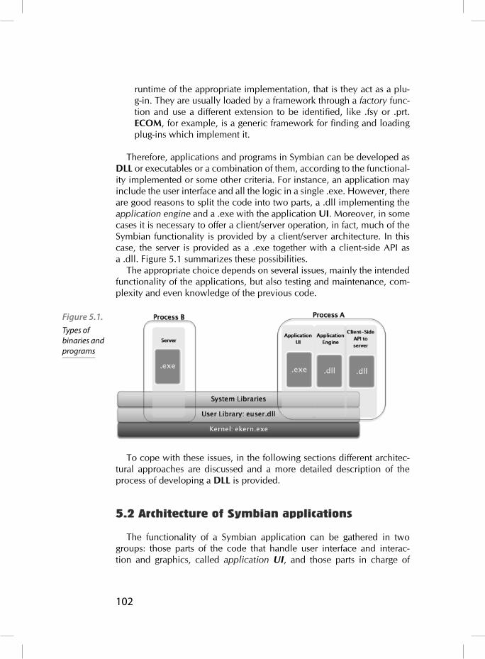
102
runtime of the appropriate implementation, that is they act as a plu-g-in. They are usually loaded by a framework through a factory func-tion and use a different extension to be identifi ed, like .fsy or .prt. ECOM, for example, is a generic framework for fi nding and loading plug-ins which implement it.
Therefore, applications and programs in Symbian can be developed as DLL or executables or a combination of them, according to the functional-ity implemented or some other criteria. For instance, an application may include the user interface and all the logic in a single .exe. However, there are good reasons to split the code into two parts, a .dll implementing the application engine and a .exe with the application UI. Moreover, in some cases it is necessary to offer a client/server operation, in fact, much of the Symbian functionality is provided by a client/server architecture. In this case, the server is provided as a .exe together with a client-side API as a .dll. Figure 5.1 summarizes these possibilities.
The appropriate choice depends on several issues, mainly the intended functionality of the applications, but also testing and maintenance, com-plexity and even knowledge of the previous code.
To cope with these issues, in the following sections different architec-tural approaches are discussed and a more detailed description of the process of developing a DLL is provided.
5.2 Architecture of Symbian applications
The functionality of a Symbian application can be gathered in two groups: those parts of the code that handle user interface and interac-tion and graphics, called application UI, and those parts in charge of
Figure 5.1. Types of binaries and programs

103
algorithms and data manipulation, called application engine. Both appli-cation UI and engine use functionality provided by the system. That is, application UI uses GUI controls and graphic components, while engine uses utility libraries for manipulating strings (ETEXT), storing data (STORE) and so on.
There are a number of ways to structure and organize the internal com-ponents of an application. How to choose the appropriate one depends on the particular purpose and functionality provided, among other considera-tions. Since the differences in the Symbian systems mostly lie in the UI platforms, it is especially important to consider the relationships between the application UI and the rest of the components. In the following sec-tions the most common approaches, their pros and cons, are discussed.
5.2.1 Single simple application
It is possible to built all the logic of an application, included UI, into a single executable, as in Fig. 5.3.. This option is usually discouraged
except for very simple applications, which do not interact with others. The drawbacks are:
High coupling between components. This is a poor coding practice in general, prevents the independent evolution of the components (UI and engine) and brings additional problems to test and main-tenance.
Diffi cult testing and maintenance. It is not possible to test the UI and engine independently.
Figure 5.2. Parts of an
application

104
On the other hand, the applications tend to be smaller and easier to build.
5.2.2 Portable UI application
To make an application portable, that is, able to operate on different platforms, it is necessary to separate the UI from the engine. It means building the engine code as a separate DLL as in Fig. 5.4.. In fact, most of the developed Symbian applications enforce this architecture. This way, UI and engine interoperate through an established interface (defi ned by the .dll exported functions). Engine components are passive generally, in the sense that they are invoked by UI components.
The advantages are:
It allows independent development, evolution and testing of both components, as long as the interface remains unchanged.
It promotes reuse of code and functionality, especially if the latter is used by different applications.
Although this approach is easier to maintain, there is still high coupling between application UI components and engine. Remember that appli-cations are made of views and user interaction on them results in data modifi cation. Embedding engine calls directly in view code makes port-ability complex and diffi cult. Besides, GUI frameworks are more complex than the simplifi ed view provided in Fig. 5.4. Therefore, it is advisable to achieve an even looser coupling between components as shown in the following section.
Figure 5.3. Architecture of a single-exec application

105
5.2.3 Model-View-Controller application
The MVC is a programming pattern widely used in UI applications. It allows to decouple UI from its underlying data model by using a new component, the controller which is in charge of the policy, that is how changes in view and model are handled, see Fig. 5.5.. This way, views can be easily replaced when necessary. A possible Symbian architecture is shown in Fig. 5.5.
Figure 5.4. Architecture of
a UI portable application
Figure 5.5. Model-View-
Controller pattern

106
The View manages the presentation and manipulation of graphical information being displayed. The Model is responsible for data manipu-lation and state. The Controller handles interactions between the other components. It includes specifi cally user input and interaction.
The Symbian Application Framework, briefl y reviewed in Sec. 5.2.4. and more thoroughly described in Chapter 9, enforces the use of a MVC paradigm for application development. However, the roles of the differ-ent components provided in this framework are not so clearly defi ned. For instance, the View and the Controller are usually implemented in the same class, that is the user interaction is directed to UI components.
5.2.4 Symbian Application Framework
The Symbian Application Framework is a set of system libraries that provides considerable abstract functionality to be used in application development. It also provides particular functionality, especially system GUI. Fig. 5.7. shows a very simplifi ed view of the framework.
Applications are developed by deriving classes from both AppArc and CONE and implementing their virtual methods.
AppArc provides functionality to launch applications and load its data and other related tasks. CONE provides the basic blocks of GUI function-ality, that is controls. Those generic controls are refi ned by the System GUI, which is made of a generic part called Uikon and the look-and-feel provided by a different platform UI, known as *kons, that is Avkon, Qikon, Sakkon, and TechView.
Figure 5.5. Dual Symbian Model-View-Controller pattern

107
Symbian applications are made of at least four components: Applica-tion, Document, AppUi, AppView (described in Ch. 9) plus an Engine. Fig. 5.8. shows how each of them fi ts in the Application Framework and how they implement the MVC paradigm.
Application engine matches the Model in the MVC paradigm, since it manages application data. The View corresponds to AppView, which is derived from CONE functionality. The Controller is, however, distributed in several components in the Symbian Application Framework. Appli-cation, AppUi and Document perform the Controller role. Specifi cally, AppUi handles user commands, whereas Document uses the interface to the Application Engine.
Figure 5.7. Symbian
Application Framework
Figure 5.8. MVC and Symbian
Application Framework

108
5.2.5 Client/server application
The client/server models play an important role in Symbian, since much of the system functionality is provided by different servers, like the fi le or window server. Some applications may provide functionality for many others. In those cases, it is useful to implement the application engine as a server. Servers are very useful basically when:
Functionality is shared by several applications. Servers provide an effi cient way to share resources and manage concurrent access.
Isolation between processes. Servers run in their own process and so can ensure the security or integrity of the resources being shared.
Asynchronous operation is desirable. Servers and active objects pro-vide asynchronous support for applications.
Servers are made of an executable, the server itself, and the client-side API to the server as a DLL which can be used by other applications. Serv-ers are described in detail later in Ch. 7.
5.3 Developing an engine as a DLL
In the previous sections it has been shown that in most cases it is advis-able to separate an engine from an application UI. Engines, then, are provided as a DLL which is imported by the application UI code; or as plug-ins, loaded at runtime by a framework, and, thus, used by the appli-cation through the framework interface. It is necessary, therefore, to take a deeper (yet brief) look at the DLL development process.
In this section, the basics of DLL development are provided. Both static and polymorphic interface DLL are considered. The Symbian security model and DLL security issues are briefl y described as well.
5.3.1 Polymorphic interface DLL
Polymorphic interfaces DLL are used to provide different imple-mentations of a common interface. They are based on a factory pat-tern. All the implementations derive from an abstract base class, which defines the interface and implements its virtual functions. An instance of a particular derived class is obtained by a call to a method on a factory class, which knows about the available implementa-tions.Therefore, polymorphic DLL are loaded at runtime by a call to RLibrary::Load(). This call is typically done by a system frame-work. In fact, polymorphic DLL are normally used as plug-in modules

109
to some system framework, like the communications server, the file server, the media server and so on.
The framework provider supplies the interface, that is a header and defi nition fi le for the library, whereas the plug-in provider supplies a DLL fi le, though historically it was identifi ed with particular extensions other than .dll. When loading the plug-in, it is necessary to identify the particu-lar implementation, usually with a fi le name. To avoid this drawback and provide more fl exibility Symbian introduced a generic plug-in framework called ECOM.
5.3.2 ECOM plug-in architecture
The ECOM framework was introduced in Symbian to manage the dis-covery, loading and unloading of plug-ins. These tasks include deter-mining the particular implementation to instantiate and its instantiation method, so simplifying the programming of plug-ins. A client frame-work simply calls the factory function of the interface. The interface is declared in a header fi le, which contains a static function that instanti-ates an implementation of the interface as well as a unique identifi er for the interface.
Plug-in providers supply a particular implementation as a DLL plus a registration fi le that associates it to the interface identifi er. The ECOM server searches for available implementations of interfaces.
To use an interface, the client code includes the interface header and uses the interface factory function (e.g. NewL()) to instantiate an imple-mentation. Internally, this method calls the ECOM server with REComSession::CreateImplementationL(), which looks at the registered implementations and returns and appropriate instance. When fi nished, the client calls the destructor, which informs the ECOM server. It uses reference counting to manage shared resources. Figure 5.9. summarizes this mechanism.
Figure 5.9. ECOM
architecture

110
5.3.3 Static interface DLL
A static interface DLL is so called because of two reasons: fi rst, unlike polymorphic interfaces, there is only one implementation of the interface; second, even though its internal implementation may change, the inter-face should remain fi xed in order to be usable for its clients, that is to maintain binary compatibility. At any time there is only one instance of a static interface DLL loaded at the system. It is loaded when an applica-tion that uses it is loaded fi rst. If more than one application uses the same DLL, reference counting is used to keep only one instance loaded and manage its destruction.
A static DLL provider must supply three fi les to its users:
A header fi le (.h), included in the client code and used in compilation. An import library fi le (.lib), which contains the list of functions expor-ted by the DLL, used in linking.
The compiled library (.dll), which is a binary that contains an export table, that is the particular functions available to be used by the library clients.
Implementing a static interface DLL requires the following tasks:
Figure 5.10 Building a static interface DLL

111
Declaring the interface in a header fi le. This step involves some important choices: fi rst, deciding which functions should be expor-ted. In fact, it means deciding which is the interface of the library. It should be considered also if the classes can be derived, and thus, which are the virtual methods that can be overridden. To export a function its prototype must be preceded with the macros IMPOR-T_C and EXPORT_C in the header (.h) and implementation (.cpp) fi le respectively.
Implementing the library. Creating a project defi nition fi le (.mmp). In this fi le the TARGETTYPE must be dll to create the import and library fi les. In the UID state-ment the UID2 is used to distinguish static and polymorphic libraries. For a static one it must be set to 0x1000008d. The next value, the UID3 must uniquely identify any component and can be obtained from Symbian Signed in the usual way.
Adding the project to the component description fi le (bld.inf). It is used to let the build tools to export the headers to specifi c locations.
During the building process of a DLL several fi les are created, as shown in Fig. 5.10. After compiling, object fi les are created. These fi les are linked against any other object and library fi les and a frozen defi nition fi le. The output are the fi les needed to use the library: the import and library fi les as well as the defi nition fi le.
To use a DLL the client source code must include its header fi le and the project defi nition (.mmp) must include the library fi le and its path.
5.3.4 Security
Like all the executables, DLL are subject to the Symbian security model based on capabilities. Every DLL is assigned a set of capabilities. Applying the Symbian capability rules, in practice, means determining the process that can use it. That is, according to Rule 2 a process can only load a DLL if it has at least the same capabilities as the process. So, a process with less capabilities than a given DLL will never be able to load it, whereas a DLL with more capabilities than the loading process will effectively be downgraded to the set of capabilities of the using process. This rule is valid also for any chain of DLL being loaded, that is when a DLL tries to load another one.
When a DLL statically links to another one, the same rule applies, that is the former will only be loaded if the latter is trusted with at least the same capabilities as the fi rst one. Let us remark on the difference here with an example: a polymorphic interface DLL, such as an ECOM plug-in will be able to load another library with less capabilities but at least the same

112
as the calling process, because it is done dynamically at runtime, and it will be used in the context of the calling process. For statically linked DLL (the majority in Symbian), it is not possible, since loading the fi rst one is effectively equivalent to loading both of them.
5.3.5 Binary compatibility
Binary compatibility may be defi ned as the ability to keep working two interdependent components, like a DLL and a client code, without recom-piling or relinking, even when one of them is modifi ed. Binary compatibil-ity is a specially important issue with DLL. Since their functionality may be shared by several applications and one of their advantages is that both library and client code can evolve independently, it is crucial to ensure that future modifi cations do not prevent them from working. Theoreti-cally, as long as the shared interface remains unchanged, compatibility should be guaranteed. In practice, and due to some particularities of the Symbian systems, there are some points to consider.
The fi rst one is related to what exactly is the shared interface. The inter-face of a DLL from the point of view of its users is made of the follow-ing components: the header fi le (.h), used at compiling time; the import library fi le (.lib), used at linking time; the export table contained in the DLL, used at runtime, the virtual function table contained in the DLL, also used at runtime and the expected behavior of the functions. Therefore, all these components should remain unchanged (to some extent) to keep binary compatibility. In fact, some changes are possible, and depending on the nature of the changes binary compatibility can still be achieved. For instance, it is possible to change the implementation of a function to fi x a bug without breaking binary compatibility.
Figure 5.11. Internal relationships between a DLL and a client code
113
A closer look at the operation of shared libraries is useful to under-stand binary compatibility. Fig. 5.11. shows a diagram of the relationships among the aforementioned components. Due to device limitations, the size of DLL in the Symbian OS is optimized to be as small as possible. One of these optimizations is that function lookup in shared libraries is done only by the order in which they are exported in the module defi ni-tion fi le. Unlike other operating systems where lookup by name is pos-sible, Symbian links just by ordinal. It means that this order cannot be changed in order to maintain binary compatibility. Fixing the order of functions in an import fi le (.lib) avoids breaking binary compatibility. It is called freezing the fi le. The Symbian tool chain enforces this behavior: abld refuses to generate a .lib fi le for a DLL unless the interface is frozen or the EXPORTUNFROZEN statement appears in the .mpp fi le. In Fig. 5.10. it is shown that a frozen defi nition fi le is necessary in the building process.
There are a number of actions, related to the previously explained behavior of the Symbian operating system, that break binary compatibil-ity, summarized in the following list:
Changing the size of class or data members. Unless it can be guaran-teed that the object can only be instantiated in the heap.
Reordering the exported functions. Since each function is assigned an ordinal in the module defi nition fi le, as said previously. It actu-ally depends on the build tools and can be avoided by freezing the library.
Changing the order of data members. Data members are accessed by adding a fi xed offset to the object pointer in the header fi le, which the client compiles against.
Changing accessibility. Methods and members can be made more accessible only, otherwise binary compatibility is broken.
Reordering enums. Removing const from parameters, return types or methods. Changing the way parameters are passed, by value or reference.
There are also some more subtle issues with virtual functions and inher-itance that will not be covered here. In addition, there are some good practices to ensure the code will be compatible in the future that are not discussed here either.

114

115
Client-Server architecture
Most of the system resources in Symbian are provided through client-server framework, in particular those which provide asynchronous func-tionality. Servers are used to manage shared access to system resources and services so that several clients are able to access the same resource simul-taneously. Applications and the rest of the services act as clients. This is the behavior shown in fi gure 6.1., where different clients gain access to system resources through a well defi ned API provided by the system server. Some examples of system resources managed by these servers are fi les, sockets, telephone calls, agenda, UI resources, serial communications etc.
This chapter will focus on how to access system servers from their client-side APIs. In particular fi le and socket client-side APIs will be introduced.
6.1 Introduction to the client-server architecture
Servers run operate in a separate thread and most of the time in a sepa-rated process. Server memory address cannot be accessed by clients, so the integrity of resources is preserved. Due to this, client-server communi-cation is carried out by inter-thread communication mechanisms mediated by the kernel (see fi gure 6.2.). But the access to system resources from the application code can be made transparent to this complex mechanisms through a well-defi ned interface: the client-side API. APIs are provided by servers through separate dynamic link libraries (DLL), .h fi les with the
6
Figure 6.1. Client-Server
Model Overview

116
declaration of the methods and .lib fi les containing the list of the exported methods which will be requested by the linker. In fi gure 6.3. we can see the level at which each of these fi les is used. Client-side APIs are based in two Symbian classes: RSessionBase and RSubSessionBase.
Figure 6.2.Client-Server Architecture
Figure 6.3. Client-side DLL

117
6.1.1 Sessions and sub-sessions
The class RSessionBase is the base class for client-side session API, while RSubSessionBase is the base class for sub-session APIs. The communication channel between the client and the server is known as a session. Client requests are sent as messages over this session. Most of the requests are asynchronous although requests can also be synchronous. Only one synchronous request may be submitted at a time but multiple asynchronous requests may be outstanding. So it is more effi cient to use asynchronous requests.
A server supports sessions from multiple clients and multiple sessions from the same client. Each session requires a set of resources in the kernel and in the server. So for effi ciency reasons the number of sessions should be minimized. Due to this, when multiple sessions from the same client are required it is more effi cient to use multiple sub-sessions, as a sub-session consumes fewer resources than a session. Using the fi le server as an example, each sub-session would represent a fi le.
6.2 Using client-side APIsClient-side APIs are provided for client applications in order to simplify
the access to the server interface which hides the implementation details of the message passing protocol to the users’ applications. Client APIs are constituted by R classes derived from RSessionBase and RSubSes-sionBase classes and which provide the following basic functionalities:
Connecting to the system server Making requests to the system server Receiving data from the system server
At the fi rst step a session must be established with the server. Usually the RSessionBase derived class provides a Connect() or Open() method. Additionally, sub-session APIs provide the methods needed to create a sub-session in the context of such a session. After the session is created the sub-session APIs will use this session to send requests to the server. Client-side API also provides methods to transmit the request mes-sages from the client to the server. The connection to a server must be closed after use, otherwise a resource leak will take place.
In order to use client-side APIs the corresponding .lib fi le must be included in the LIBRARY fi eld of the project fi le (MMP fi le). Also, the header fi le should be included in the source fi le where the handler is instantiated. For example, efsrv.lib library should be added to the project fi le if the application accesses the fi le server, and the header fi le

118
f32fi le.h should also be included in the source code of the application.As has been mentioned, methods provided by client-side API to send
messages to the server are usually asynchronous. But some APIs provide also the synchronous version of the method.
6.3 File server
The code shown in the fi gure is an extract from the fi le server client-side API. RFs class represents a session with the fi le server, while RFile class represents a sub-session. As we commented before, from the point of view of the resources consumed by sessions and sub-sessions it is more effi cient to use a sub-session to represent a fi le. RFile class provides a method Open to open a sub-session with the fi le server. Also method Read() and Write() are offered with two different implementations: synchronous and asynchronous.
class RFs: public RSessionBase {…}class RFsBase: public RSubSessionBase {…}
class RFile: public RFsBase{ public: IMPORT_C TInt Open (RFs& aFs, const TDesC& aName, Tuint aFileMode); IMPORT_C TInt Create (RFs& aFs, const TDesC& aName, Tuint aFileMode);
IMPORT_C TInt Read (TDes8& aDes) const; IMPORT_C void Read (TDes8& aDes, TRequestStatus& aStatus) const;
IMPORT_C Tint Write (const TDesC8& aDes); IMPORT_C void Write(const TDesC8& aDes, TRequestStatus& aStatus);
R classes are system resource handler. When a program fi nishes its execution all its resources must be destroyed; it implies that all the han-dlers (R object) used in the program must be closed. If the R object is owned by a CBase derived class, the Close() method of the R object must called in the destructor of the CBase derived class. When R object is declared as an automatic variable cleanup stack mechanisms must be used to be sure that the handler is correctly closed in case an exception
Listing 6.1. File server client-side API

119
occurs. The following piece of code shows the way cleanup stack meth-ods should be used:
void CExampleFileServer::Read(const TDesC& aFileName) { RFs fs; RFile fi le; TBuf8<10> data;
//open the server session User::LeaveIfError(fs.Connect());
//handle is put on the cleanup stack CleanupClosePushL(fs);
//open a subsession User::LeaveIfError(fi le.Open(fs, aFileName, EFileRead)); //put the handle on the cleanup stack CleanupClosePushL(fi le);
//the beginning of the fi le is read fi le.Read(data,10);
//two handles are closed and removed from the stack CleanupStack::PopAndDestroy(2);
}
After declaring the R object it should be pushed on the cleanup stack by calling method CleanupClosePushL. After that we can use the object normally and if a leave occurs all the resources pushed on the cleanup stack will be closed.
Assuming the reading went well the call CleanupStack::PopAndDestroy() will pop and destroy the fi le server sub-session and session from the cleanup stack and close both objects.
Listing 6.2. Client
application example code

120
6.4 Symbian Socket API
Symbian socket API provides a socket implementation very similar to BSD (Berkeley Software Distribution) C-based socket API. It provides sup-port for using internet family protocols (TCP, UDP, DNS, IP...) and also Bluetooth and Infrared protocols.
The main classes provided by this API are RSocketServ and RSocket. Both classes are defi ned in the fi le es_sock.h. The user application where these classes are used must be linked against the library esock.lib. To use a socket connection NetworkServices capability is required. Other useful classes provided are RHostRe-solver, which provides host resolver functionality, and RConnec-tion which, among other functionalities related to the status of the con-nection, makes it possible to select a specifi c bearer to be used by the socket connection.
6.4.1 RSocketServ
RSocketServ class provides connectivity to the socket server (ses-sion). It is a container for all the socket connections established by the application, but it does not provide methods to create a connection with a remote machine or send and receive data. The class that represents the common Berkeley socket concept is RSocket. Before using RSocket objects in the user application a session with the socket server must be open in the way shown in the following piece of code:
RSocketServ sockServ;// Connect to socket server (open a session)User::LeaveIfError (sockServ.Connect());
6.4.2 RSocket
RSocket class represents the end point for a socket-based communica-tion. In the Symbian client/server terminology RSocket class represents a sub-session, which is always associated with a session with the socket server. RSocket provides the functionalities to connect, receive and send data through a socket, among other services. A socket is uniquely identi-fi ed by a machine address and a port number. The class TInetAddr, defi ned in in_sock.h (link against insock.lib), is used to represent an IP address and port.
6.4.3 RHostResolver
Listing 6.3. Opening a socket server session

121
RHostResolver is a class which represents also a sub-session in the context of a session. This class provides the interface for host name resolu-tion services.
6.4.4 Using Socket API
After opening a session with the socket server (using an instance of the class RSocketServ) a socket can be opened. The RSocket::Open() method of the class RSocket receives as the fi rst argument the session opened with the server socket, as can be seen below:
TInt Open (RSocketServ& aServer, TUint addrFamily, TUint sockType, TUint protocol);
The rest of parameters that must be provided during the socket opening are the protocol type, the socket type and the address family.
Address families supported in Symbian are defi ned in in_sock.h:
KAfInet. Internet sockets. KIrdaAddrFamily. Infrared sockets. KBTAddrFamily bt_sock.h (link against bluetooth.lib). Bluetooth sockets.
Socket types are defi ned in the fi le es_sock.h}. Typically, the socket type is one of the following:
KSockStream. Connection-Oriented KSockDatagram. Datagram socket
The protocol argument to the RSocket::Open() socket call is also defi ned in the fi le in_sock.h:
KProtocolInet6Ip. IPv6 KProtocolInetTcp. TCP KProtocolInetUdp. UDP KProtocolInetIp. IPv4 KUndefi nedProtocol. The selection of the protocol is done by the socket server.
Bind, listen and accept incoming connectionsIn this section we will explain in more detail the parameters used to call
RSocket::Bind(), RSocket::Listen(), RSocket::Accept()method during the implementation of a server which accepts incoming socket connections.
Listing 6.4. Opening
a socket

122
RSocket::Bind(). Set the address and the port of the listening socket.
RSocket socket, serviceSocket;RSocketServ socketServ;TInetAddr addr;addr.SetAddress(KInetAddrAny);addr.SetPort(80);socket.Bind(addr);
RSocket::Listen(). The socket is confi gured to be able to rece-ive incoming connections. A queue for the incoming connections is established.
//Size of Listen Queueconst TUint KSizeOfListenQueue = 1;
//Open listen socketsocket.Open(socketServ, KAfInet,KSockStream, KProtocolInetTcp);
//Listen for incoming connectionssocket.Listen(KSizeOfListenQueue);
RSocket::Accept(). Waiting for an incoming connection. When a new connection is received this method creates a new socket with the same properties as the listening socket. This socket will be used by our server to communicate with the new client.
//Create a blank socketserviceSocket.Open(socketServ);
socket.Accept(serviceSocket, status);User::WaitForRequest(status);
Reading and Writing with socketsAfter a connection has been accepted data is sent and received. All
the methods provided by RSocket to read and write with sockets are asynchronous.
IMPORT_C void Read(TDes8 &aDesc, TRequestStatus &aStatus);IMPORT_C void Recv(TDes8 &aDesc, TUint fl ags, TRequestStatus &aStatus);
Listing 6.5. Binding a socket
Listing 6.6. Listening
Listing 6.6. Waiting for incoming connections
Listing 6.8. Send and receive methods
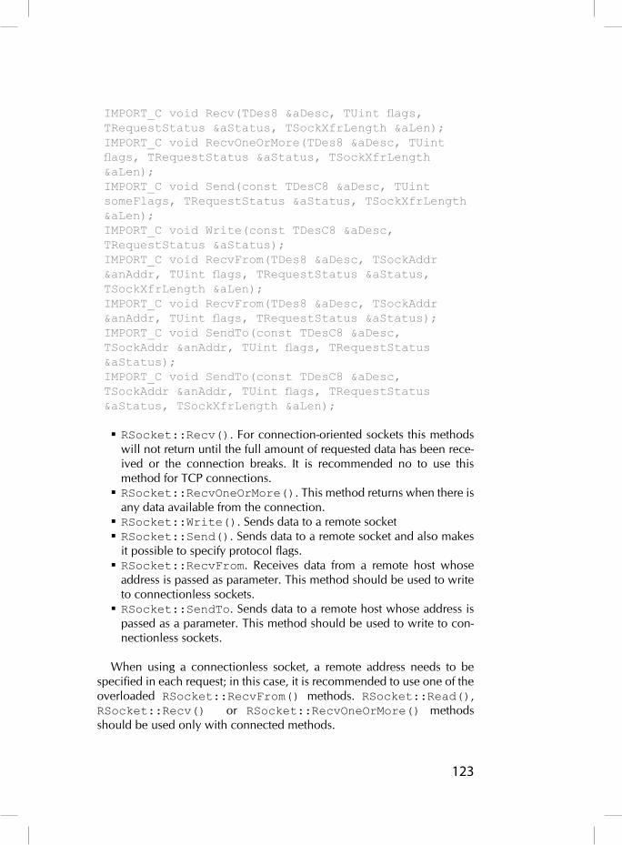
123
IMPORT_C void Recv(TDes8 &aDesc, TUint fl ags, TRequestStatus &aStatus, TSockXfrLength &aLen);IMPORT_C void RecvOneOrMore(TDes8 &aDesc, TUint fl ags, TRequestStatus &aStatus, TSockXfrLength &aLen);IMPORT_C void Send(const TDesC8 &aDesc, TUint someFlags, TRequestStatus &aStatus, TSockXfrLength &aLen);IMPORT_C void Write(const TDesC8 &aDesc, TRequestStatus &aStatus);IMPORT_C void RecvFrom(TDes8 &aDesc, TSockAddr &anAddr, TUint fl ags, TRequestStatus &aStatus, TSockXfrLength &aLen);IMPORT_C void RecvFrom(TDes8 &aDesc, TSockAddr &anAddr, TUint fl ags, TRequestStatus &aStatus);IMPORT_C void SendTo(const TDesC8 &aDesc, TSockAddr &anAddr, TUint fl ags, TRequestStatus &aStatus);IMPORT_C void SendTo(const TDesC8 &aDesc, TSockAddr &anAddr, TUint fl ags, TRequestStatus &aStatus, TSockXfrLength &aLen);
RSocket::Recv(). For connection-oriented sockets this methods will not return until the full amount of requested data has been rece-ived or the connection breaks. It is recommended no to use this method for TCP connections. RSocket::RecvOneOrMore(). This method returns when there is any data available from the connection. RSocket::Write(). Sends data to a remote socket RSocket::Send(). Sends data to a remote socket and also makes it possible to specify protocol fl ags. RSocket::RecvFrom. Receives data from a remote host whose address is passed as parameter. This method should be used to write to connectionless sockets. RSocket::SendTo. Sends data to a remote host whose address is passed as a parameter. This method should be used to write to con-nectionless sockets.
When using a connectionless socket, a remote address needs to be specifi ed in each request; in this case, it is recommended to use one of the overloaded RSocket::RecvFrom() methods. RSocket::Read(), RSocket::Recv() or RSocket::RecvOneOrMore() methods should be used only with connected methods.

124
Closing socketsBefore a socket is closed all the pending requests should be fi nished by
calling RSocket::CancelAll() method. After that, the socket can be closed synchronously with the method RSocket::Close().
When the socket needs to be closed asynchronously, RSocket::Shutdown(TShutdown aHow, TRequestStatus &aStatus) method should be used. This type of disconnection is rec-ommended before closing the socket when using connection-oriented protocols.RSocketServ session must be closed after all the sockets (sub-ses-
sions) have been closed, otherwise a panic occurs.
6.4.5 Connection-oriented socket communication
During a connection-oriented socket communication a connection is established between two endpoints. This connection will be used dur-ing the entire lifetime of the communication. The address and port of the other endpoint must be specifi ed only during the establishment of the connection. TCP (Transmission Control Network) is the transport pro-tocol associated with this type of connections. Sock type parameter for connection-oriented socket, also called stream sockets, is KSockStream.
Figure 6.4. shows the typical lifecycle of a connection-oriented communica-tion between a client and a server.
Figure 6.4. Connection-oriented socket lifecycle

125
On the server side there is one socket for accepting incoming connec-tions. This socket binds to a local address and port number; at this point the operating system knows that all the packets received in the specifi ed address and port must be sent to this server. Also, a queue for listening to incoming connections is confi gured. After that RSocket::Accept() method is called and the socket will wait for the reception of incoming connections in the address interface and the port confi gured previously. When a connection is received from a client application, hosted in the same or in another machine, the Accept() call will return a new socket to handle the communication with the client. After the connection has been successfully established the server and the client will communicate through a continuous stream of bytes, using the new socket, until the end of the connection.
_LIT(KAddr, “192.168.2.1”);const TInt KPort = 21;
RSocketServ ss;RSocket socket;TRequestStatus status;TSockXfrLength recvlen;TBuf8<10> buffer;TInetAddr destAddr;
//Socket Server session is openedss.Connect();
//Open socketsocket.Open(ss, KAfInet, KSockStream, KProtocolInetTcp);
destAddr.Input(KAddr);destAddr.SetPort(KPort);
//connectionsocket.Connect(destAddr, status);User::WaitForRequest(status);
//Readingsocket.RecvOneOrMore(buffer, 0, status, recvlen);User::WaitForRequest(status);
//End of the connection
Listing 6.9. TCP client
connection establishment

126
socket.Close();ss.Close();
Listing 6.10. TCP server connection establishmentconst TUint KLocalPort=3333;_LIT8(KWelcome, “Welcome”);
RSocketServ ss;RSocket socket; listenSocket;TRequestStatus status;TInetAddr localAddr;TBuf8<10> buffer;
//Socket Server session is openedss.Connect();
// Need to use two sockets – one to listen for// an incoming connection.listenSocket.Open(ss, KAfInet,KSockStream, KProtocolInetTcp);
// The second (blank) socket is required to// build the connection & transfer data.socket.Open(ss);
// Bind the listening socket to the required// port.localAddr.SetAddress(KInetAddrAny);localAddr.SetPort(KLocalPort);listenSocket.Bind(localAddr);
// Listen for incoming connections...listenSocket.Listen(1);
// and accept an incoming connection.// On connection, subsequent data transfer will// occur using the socketlistenSocket.Accept(socket, status);User::WaitForRequest(status);
buffer.Copy(KWelcome);
//Sending

127
socket.Send(buffer, 0, status);User::WaitForRequest(status);
//End of the connectionsocket.Close();ss.Close();
Listing 6.11. Connected socket: send and receive_LIT8(KHello, “Hello”);
TSockXfrLength len;TBuf8<10> buffer;RSocket socket;TRequestStatus status;
buffer.Copy(KHello);
//sending datasocket.Write(buffer, status);User::WaitForRequest(status);
// clean bufferbuffer.Zero();
//receiving dataserviceSocket.RecvOneOrMore(buffer, 0, status, len);User::WaitForRequest(status);

128
6.4.6 Connectionless socket communication
Figure 6.5. shows the lifecycle of a connectionless socket communi-cation between a server and a client. There is no connection between both of them. Data interchange between both entities is carried out as discrete datagrams, so each datagram requires the destination address and each received packet is processed independently of the rest. Usually, the datagram protocol used by IP connections is UDP (User Datagram Protocol). Sock type parameter for a datagram socket is KSockDatagram.
For a client using connected sockets there is no need to set a local address because it is done as apart of the connection process. For connec-tionless sockets, in a server or in a client, the local address and port must be specifi ed by using the method RSocket::Bind. Once the datagram socket is bound to a local address and port it is ready to start sending or receiving data.RSocket::RecvFrom() method is used to receive datagrams. This
method returns data received from a remote host and the address of the datagram source.
Figure 6.5. Connectionless socket lifecycle

129
The method used to transmit data to a remote host is RSocket::SendTo(). This method receives as the fi rst parameter a reference to a descriptor which contains the data to be transmitted. As the second parameter we should provide the address of the destination host.
RSocketServ ss;RSocket socket, listenSocket;TRequestStatus status;TInetAddr localAddr, destAddr;TBuf8<10> buffer;Int localPort=3333;Int destPort=3334;
//Socket Server session is openedss.Connect();
//Open the datagram socketsocket.Open(ss, KAfInet, KSockDatagram, KProtocolInetUdp);
localAddress = TInetAddr( KInetAddrAny, localPort );
//Bind the socket to a local address and portsocket.Bind(localAddr);
//Confi guration of the address and port of the destination hostdestAddr.SetPort(destPort);destAddr.SetAddress(INET_ADDR(80,80,80,80));
socket.RecvFrom(buffer, destAddr, 0, status);User::WaitForRequest(status);
6.5. Example: TCP/IP Client connection using Active-Objects
Typically, client applications use active objects to handle asynchro-nous requests in the client-server framework. What follows is an exam-ple of how Symbian Socket API can be handled by implementing a state machine using active objects.
Listing 6.12. Connectionless
socket communication

130
The example shown in this section illustrates the use of zan active object for implementing a client application which receives and sends data to a server running in a remote machine.
6.5.1 TCP/IP Client class defi nition
The code below shows the defi nition of the client class [in charge of]managing the socket used to communicate with the server. An enumerate type CTcpIp::TSocketState has been defi ned to represent the cur-rent state of the TCP/IP client.
class CTcpIp: public CActive{
//states of the state machineenum TSocketState{ EIdle, EConnecting, ESending, EReceiving, EFailed};
public: static CTcpIp* NewL(); static CTcpIp* NewLC(); ~CTcpIp();
//from CActive void RunL() ; void DoCancel(); void RequestL(); //this method initiates the //execution of the //active object !!...private: CTcpIp(); void ConstructL(); ...
TSocketState iState; // current state of the state
Listing 6.13. CTcpIp class defi nition

131
// machineRSocket iSocket; //socket to handle the data //transfer with the serverRSocketServ iSockeServ;...
}; //End CTcpIp
Note that CTcpIp class derives directly from CActive class. This class has two pure virtual methods CTcpIp::RunL and CTcpIp::DoCancel that must be implemented in CTcpIp class. CTcpIp also has as a member variable a socket which will be used to send data to and receive it from a remote server.
6.5.2 CTcpIP class construction
On construction the CTcpIp class derived from CActive must call the constructor of the base class indicating the priority of the active object as shown below.
CTcpIp::CTcpIp(): CActive(EPriorityStandard) //set the priority { }In its constructor, the TCP/IP client class should add itself to the active scheduler, as can be seen in the code below. Also, the state of the state machine is initialized and the session with the socket server is started. In this point the client is ready to use sockets.Listing 6.15 ConstructL method of CTcpIp classCTcpIp::ConstructL() { //Set the initial state iState = EIdle;
//add to the ActiveScheduler CActiveScheduler::Add(this);
// Open session to Socket Server User::LeaveIfError(iSocketServ.Connect()); }
Listing 6.14. C++
constructor

132
6.5.3 Getting connected
The method RequestL() starts the execution of the active object. The fi rst step is the opening of the member variable iSocket as shown in the following piece of code:
void CTcpIp::RequestL(){ ... //Open a socket iSocket.Open(iSockServer, KAfInet, KSockStream, KProtocolInetTcp); iState = EConnecting ; //when request is completed RunL is //called and the state //EConnecting will be performed //asynchronous request iSocket.Connect(address, iStatus) ; // Mark this object active, so that the Active Scheduler // knows it has submitted an asynchronous request SetActive();}
iSocket is defi ned as a TCP socket by using the constant KSock-Stream during its creation. After that the asynchronous method Con-nect() is called to establish the connection with a remote server. The state of the client is updated.
The object is marked as active by calling the method ActiveSet(), which will report to the Active Scheduler this active object has submitted an asynchronous request.
6.5.4 Handling the communication with a remote server
When the connection with the server is established the outstanding RSocket::Connect() request is completed and the CTcpIp::RunL() method of the active object which launched this request will be run.
As the state of the TCP/IP client was updated before the asynchronous call was launched, when the CTcpIp::RunL() method is called the content of the variable iState is consulted to remember the state of the the TCP/IP client.
Listing 6.16. Getting connected

133
After an asynchronous call has been executed we should check its com-pletion status in order to know if the request was successfully executed or not. To do this the value of the variable iStatus inherited from the class CActive is checked: if it is equal to KErrNone, it means the operation was executed successfully and we can continue with the normal execu-tion of the application. Otherwise, it would contain the error code.
After that, the code corresponding to the state EConnecting is exe-cuted. The state is updated again and the client sends an initial message to the remote server.
Also, we use an automatic variable called fi nished to indicate if there is a new asynchronous request. This variable is initialized to EFalse; when there is no new request we should modify its value to ETrue. At the end of the method CTcpIp::RunL() the value of fi nished is checked: if it is false (which means a new request has been launched) method CActive::SetActive() is called to mark again the object as active.
If the value of the variable fi nished is set to ETrue CActive::Cancel() method is called. By invoking CActive::Cancel() the method CTcpIp::DoCancel() is called.
void CTcpIp::RunL() { //This variable is used to check if the execution of the //active object should be fi nished TBool fi nished = EFalse; switch (iState) { case EIdle: break ; case EConnecting: if (iStatus == KErrNone) { //Connection has been completed successfully
//State is udpated iState = ESending;
iRequest.Copy(_L(“HELO\r\n”));
//Asynchronous request iSocket.Write(iRequest, iStatus); }
Listing 6.16. CTcpIp::RunL method (inherited
from CActive)

134
else { //Connection has not been established iState = EFailed ;
//No more asynchronous requests //active object will not be activated again fi nished = ETrue ; } break ; case ESending: if (iStatus == KErrNone) { //Data has been sent correctly
//State is udpated iState = EReceiving ;
//Data reception is initiated //a new asynchronous request //is launched iSocket.RecvOneOrMore(iResponseChunk, 0, iStatus, iResponseChunkSizePkg); } else { //Data sending has failed iState = EFailed ; //No more asynchronous requests //active object will not be //activated again fi nished = ETrue ; } break ;
case EReceiving: if (iStatus == KErrNone) { //We successfully got a chunk iResponseChunk.Zero();

135
//Ask for more data iSocket.RecvOneOrMore(iResponseChunk, 0, iStatus, iResponseChunkSizePkg) ; } else if (iStatus == KErrEof) { //Server has no more data to send //and has closed the connection iSocket.Close(); fi nished=ETrue; } else { //An error was detected during //data transfer iState = EFailed ; fi nished = ETrue ; } break ;
............ ............ if (fi nished) { // No more asynchronous requests Cancel(); } else { // A new asynchronous request outstanding SetActive(); }}//End RunL()
In the method CTcpIp::DoCancel(), depending on the state, each outstanding request should be cancelled. In such case the cancellation method RSocket::CancelAll() provided by RSocket is called to cancel any outstanding requests. Outstanding operations for a socket include: read, write, ioctl, connect, accept and shutdown. All of these operations will be completed by this call.

136
void CTcpIp::DoCancel() { // Cancel appropriate request to socket switch (iStatus) { case EConnecting: case ESending: case EReceiving: if (iSocket.SubSessionHandle() != 0) { iSocket.CancelAll(); iSocket.Close(); } break; default: User::Panic(KPanicTcpIp, ETcpIpPanic); break; }
}
In the destructor of CTcpIp class method CActive::Cancel() is called again to cancel any outstanding requests before destroying the active object.
Socket server session is closed after the socket is closed during the execution of the method CActive::Cancel().
Listing 6.19. CTcpIP class destructor
CTcpIp::~CTcpIp() { Cancel(); iSocketServ.Close(); }
Listing 6.18. CTcpIp::DoCancel method (inherited from CActive)

137
Active objects
Symbian is a strongly asynchronous operating system that provides event-driven multi-tasking. In the kernel of the operating system a multi-thread approach is used to handle concurrency in a pre-emptive manner. However, at application level this approach is not very effi cient. Active object framework is an important element of the Symbian OS because it provides the functionality necessary for event-driven multi-tasking at application level. This chapter explains various elements of this frame-work and how they are used in concurrent applications to ensure good performance.
7.1 Event-driven multi-tasking
There are applications, independently of the operating system, that consist of making function calls to request services. This services can be performed synchronously or asynchronously. When a synchronous func-tion is called, it performs the service to completion and returns to the caller passing some kind of completion code. In the case of calling an asynchronous function, it submits a request and returns to its caller, but the completion occurs some time later. From the time of request submis-sion to that of the completion, the caller can perform another task or sim-ply wait. When the completion occurs, the caller receives a signal, called event, that informs about the success or failure of the request. This type of applications are said to be event-driven. Typically, an event can come from different sources: from hardware, such as user input, or software, for example by timers. Events have to be managed by an event handler which waits for the event and then handles it.
There are different alternatives to implement the event-driven para-digm; all of them have two main requirements: to be responsive and to handle consumption carefully. Most systems use a multi-thread approach to carry out different tasks. It allows threads to share the system resources using the kernel as scheduler, but it increases the runtime. Symbian is an operating system for mobile phones, so it is embedded in devices with limited resources. It was designed to minimize aspects such as memory and to make an effi cient use of the processor resources. Thus, the Symbian OS has its own lightweight implementation of event-driven multi-tasking, called Active Object Framework. Multi-thread applications are possible in the Symbian OS, but they are not recommended for two main reasons:
7

138
Multi-thread applications are diffi cult to develop because it is neces-sary to include a synchronization mechanism between threads and shared resources have to be carefully managed.
Multi-thread applications have a high runtime cost due to the con-text switching between threads, which is higher than between active objects.
Thus, it is suitable to minimize the number of threads and the number of interactions between them.
7.2 Introduction to active object framework
Active Object Framework is the alternative proposed by Symbian to introduce concurrency and multi-task issues instead of the traditional multi-thread approach. This framework allows non-pre-emptive and co-operative multi-tasking in single-thread applications. Most applications use the Active Object Framework to obtain concurrency instead of using a multi-thread approach.
Symbian OS applications and servers consist of a single main thread in charge of event handling. This main thread contains a set of active objects that represent different tasks. Active objects are designed in such a way that a switch between active objects that run at the same thread has a lower cost than a thread context switch. In this section we will introduce the main elements of the active object framework: the active objects, the service provider and the active scheduler.
7.2.1 Active objects
Active objects are used to encapsulate requests to asynchronous serv-ice providers as well as handlers for those requests. Each active object requests an asynchronous service and handles the resulting completion event some time later. Generally, Symbian applications are single thread; however, in a thread there can be many active objects, and each can issue one asynchronous request to different service providers. Active objects also provide a mechanism to cancel an outstanding request and to handle exceptional conditions. It is worth noting that while an active object is handling an event it cannot be pre-empted; it is only possible when the event handler function returns the control to the active scheduler.
All the active objects must derive from CActive class, which is defi ned in E32user.h. Code shown below presents the main methods and members of this class. It provides members and methods for active object
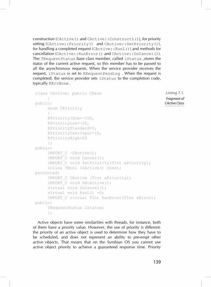
139
construction (CActive() and CActive::ConstructL()), for priority setting (CActive::Priority() and CActive::SetPriority()), for handling a completed request (CActive::RunL()) and methods for cancellation (CActive::RunError() and CActive::DoCancel()). The TRequestStatus base class member, called iStatus ,stores the status of the current active request, so this member has to be passed to all the asynchronous requests. When the service provider receives the request, iStatus is set to KRequestPending . When the request is completed, the service provider sets iStatus to the completion code, typically KErrNone .
class CActive: public CBase {public: enum TPriority { EPriorityIdle=-100, EPriorityLow=-20, EPriorityStandard=0, EPriorityUserInput=10, EPriorityHigh=20 };public: IMPORT_C ~CActive(); IMPORT_C void Cancel(); IMPORT_C void SetPriority(TInt aPriority); inline TBool IsActive() const;protected: IMPORT_C CActive (Tint aPriority); IMPORT_C void SetActive(); virtual void DoCancel(); virtual void RunL() =0; IMPORT_C virtual TInt RunError(TInt aError);public: TRequestStatus iStatus; };
Active objects have some similarities with threads, for instance, both of them have a priority value. However, the use of priority is different: the priority of an active object is used to determine how they have to be scheduled, and does not represent an ability to pre-empt other active objects. That means that on the Symbian OS you cannot use active object priority to achieve a guaranteed response time. Priority
Listing 7.1. Fragment of
CActive Class
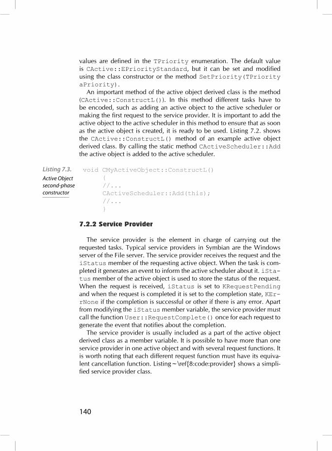
140
values are defi ned in the TPriority enumeration. The default value is CActive::EPriorityStandard, but it can be set and modifi ed using the class constructor or the method SetPriority(TPriority aPriority).
An important method of the active object derived class is the method (CActive::ConstructL()). In this method different tasks have to be encoded, such as adding an active object to the active scheduler or making the fi rst request to the service provider. It is important to add the active object to the active scheduler in this method to ensure that as soon as the active object is created, it is ready to be used. Listing 7.2. shows the CActive::ConstructL() method of an example active object derived class. By calling the static method CActiveScheduler::Add the active object is added to the active scheduler.
void CMyActiveObject::ConstructL() { //... CActiveScheduler::Add(this); //... }
7.2.2 Service Provider
The service provider is the element in charge of carrying out the requested tasks. Typical service providers in Symbian are the Windows server of the File server. The service provider receives the request and the iStatus member of the requesting active object. When the task is com-pleted it generates an event to inform the active scheduler about it. iSta-tus member of the active object is used to store the status of the request. When the request is received, iStatus is set to KRequestPending and when the request is completed it is set to the completion state, KEr-rNone if the completion is successful or other if there is any error. Apart from modifying the iStatus member variable, the service provider must call the function User::RequestComplete() once for each request to generate the event that notifi es about the completion.
The service provider is usually included as a part of the active object derived class as a member variable. It is possible to have more than one service provider in one active object and with several request functions. It is worth noting that each different request function must have its equiva-lent cancellation function. Listing~\ref{8:code:provider} shows a simpli-fi ed service provider class.
Listing 7.3. Active Object second-phase constructor

141
class CMyServiceProvider {public: ... void RequestService1(TRequestStatus& aStatus); void RequestService2(TRequestStatus& aStatus, TInt aParam); void CancelRequest1(); void CancelRequest2();private: TInt iResult; };
The service provider is initialized in the second-phase constructor of the active object(ContructL()).
7.2.3 Active Scheduler
The active scheduler is responsible for notifying the appropriate active object that a request has been completed. It is created by the operating system when an application is launched and it runs in the application’s main thread. Each (single-thread) application has at least one active scheduler.
The active scheduler encapsulates a wait loop processing of asynchro-nous events: fi rstly, the scheduler waits synchronously for the comple-tion of any outstanding request (CActiveScheduler::WaitForAnyRequest()). Then, it checks each registered active object, sorted by priority, to fi nd the owner of the completed request. After that, it calls the CActive::RunL() method of the corresponding active object and fi nally, when this method returns, the active scheduler waits again for the completion of other requests.
Active scheduler is implemented in CActiveScheduler class. Listing 7.4. shows a simplifi ed version of CActiveScheduler. The developer of an application using active objects does not need to be aware of how the active scheduler is implemented, because the Symbian OS creates it implicitly for most applications. Only for a set of special applications, for instance if the application implements a server, the active scheduler has to be created and started explicitly. The most important methods of CAc-tiveScheduler are:
CActiveScheduler::Install(): This function installs an active scheduler.
Listing 7.3. Service
Provider Class

142
CActiveScheduler::Add(): This function adds an active object to the active scheduler. CActiveScheduler::Start(): This function starts the thread’s wait loop. CActiveScheduler::Stop(): This function terminates the wait loop caused by the most recent CActiveScheduler::Start(). It causes the CActiveScheduler::Start() to return to its origi-nal caller. CActiveScheduler::Error(): This function handles the result of a leave occurring in an active object’s CActive::RunL() func-tion if that active object has a default implementation of RunError().
class CActiveScheduler: public CBase {public: IMPORT_C CActiveScheduler(); IMPORT_C ~CActiveScheduler(); IMPORT_C static void Install(CActiveScheduler* aScheduler); IMPORT_C static void Add(CActive* aActive); IMPORT_C static void Start(); IMPORT_C static void Stop(); IMPORT_C virtual void WaitForAnyRequest(); IMPORT_C virtual void Error(TInt aError) const; };
7.3 Active Object Framework life cycle
We have presented in the previous sections the main actors involved in the active object framework: the application, the active object, used by the application to make asynchronous request, the service provider that attends the request, and the active scheduler that is in charge of handling the events produced when the request has been completed. Now we will show how they act simultaneously to achieve a multi-task environment. Figure 7.1. shows the life cycle of active object framework:
For most Symbian OS applications, when they are launched, the OS creates and installs an active scheduler. This element is able to han-dle events of different active objects. For some types of applications, such as console applications or servers, the active scheduler is not implicitly created by the operating system. In these cases, we have to
Listing 7.4. Fragment of CActiveScheduler Class

143
explicitly create and install the active scheduler calling the methods CActiveScheduler::CActiveScheduler()and CActive-Scheduler:: Install (CActiveScheduler* aSchedu-ler) from the main entry point of the application.
Before starting the active scheduler, we should create at least one active object and make a fi rst request. This active object is created in the second-phase constructor of the appui class and the fi rst requ-est is usually made in the second-phase constructor of CActive deri-ved class. The request function has to pass the iStatus member to the service provider, as well as other parameters. For instance, in the CTelephony class, the asynchronous request CTelephony-::GetBatteryInfo() needs as parameter a CTelephony::T-BatteryInfoV1Pckg class which is fi lled with battery information on completion.
After issuing the request, the active object calls the CActive::Se-tActive() method to indicate to the active scheduler that it has an outstanding request. At this point, the active scheduler should be started if it was not, and it enters a wait loop for request completion.
When the service provider receives the request, it sets the \cpp{iSta-tus} member of the active object to KRequestPending to indicate that the request is not completed yet.
The active scheduler is then started with CActiveSchedule-r::Start() method and performs the wait loop, until the com-pletion of the request, CActiveScheduler::WaitForAnyRe-quest(). If the active scheduler is started without any outstanding requests, no events are caught and the thread is hung.
When the service provider completes the request, it sets iStatus member to a different value, such as KErrNone, to indicate the com-pletion code of the request. Then, it must call either User::Requ-estComplete() or RThread::RequestComplete() methods to inform the active scheduler about the request completion. When the service provider and the active object are in the same thread, User::RequestComplete() is called, and when they are in dif-ferent threads RThread::RequestComplete() is called.
When the active scheduler detects that the request is completed, it has to check which active object is the owner, that is who has issued the request. The active scheduler uses a list of active objects ordered by priority to decide which is the next active object to handle a requ-est completion. If only one request has been completed, that list only contains one active object. If several requests have been completed at the same time, the list contains all owners.
When the active scheduler selects the active object, it has to call the corresponding CActive::RunL() method. This method will

144
perform different actions depending on the implementation, such as re-issuing the request or stopping the active scheduler and fi nishing the application.
The next subsections give more detailed information about how these actions are performed giving some illustrative example code.
\label{8:fi g:lifecycle}
7.3.1 Creating and installing the active scheduler
When an application is launched, the system creates and installs auto-matically an active scheduler for this thread. The part of the system in charge of this task is the CONE framework. However, when the applica-tion is a console application or a server, the active scheduler has to be created implicitly. In such cases these tasks have to be explicitly included in the code of the application. The sequence of functions called for active scheduler creation and installation are shown in Listing 7.5.
CActiveScheduler* scheduler = new (ELeave) CActiveScheduler;CleanupStack::PushL( scheduler);CActiveScheduler::Install( scheduler););
Figure 7.1. Active Object framework life cycle
Listing 7.5. Active Scheduler Creation and Installation

145
7.3.2 Adding the active object to the active scheduler
Once the active scheduler is created and installed, we have to include the active objects in the scheduler before making any request. This task is typically done during the construction of the active object to allow its use as soon as it is created. Listing 7.6. shows how to add an active object in the second-phase constructor. CActive::ConstructL() is also used to make the fi rst request to the service provider and register it in the active scheduler.
void CMyActiveObject::ConstructL() {
CActiveScheduler::Add(this);
// Make and asynchronous request iRequest.Connect(iStatus);
//Mark this object as active SetActive(); }
7.3.3 Asynchronous request
As we saw in Listing 7.3., the asynchronous service provider supplies public methods to submit requests. One active object can use more than one of these methods although it can have only one outstanding request. Request methods should follow these rules:
Each active object can only have an outstanding request, so that each request method is in charge of checking that there is no previous request submitted. If there is a previous request, the method can per-form different actions depending on the implementation, from rising a panic, to cancelling the previous request and sending the new one.
The active object has to pass its iStatus member variable as the TRequestStatus& parameter of the request method.
If the request has been submitted successfully, the request method calls the CACtive::SetActive() method of the CActive class to inform the active scheduler that the request has been submitted.
This process is refl ected in the Listing 7.7.; this fragment shows a method to make an asynchronous request. First, it is checked if there is a previ-ous request pending. Only one request may be outstanding; by calling
Listing 7.6. Active Object
registration into the Active
Scheduler

146
CActive::Cancel() it is assured that previous outstanding requests are cancelled. In this example the service being requested is the telephony server service which requests a notifi cation of signal strength changes. When the request is completed the information relating to the event is stored in iEvent. Finally, the CActive::SetActive() method is called to inform the active scheduler about the request.
void CMyActiveObject::RequestL() { if (IsActive()) { Cancel(); } iRequest.NotifyChange(iStatus, ESignalStrengthChange, iEvent); SetActive(); }
7.3.4 Event handling
When the service provider fi nishes the actions requested, a com-pletion event is generated by the service provider. The active sched-uler has to select the appropriate active object and call the appropriate CActive::RunL() method. CActive::RunL() is a virtual method of CActive class that has to be implemented in each active object derived class. When CActive::RunL() method is being executed, this active object cannot be pre-empted by other active objects’ event handler. Thus, a good planning of CActive::RunL() code is necessary, to complete the actions needed as soon as possible, and to allow other events to be handled.
Listing 7.7. shows an example of CActive::RunL() implementa-tion. Typically, an active object can issue different asynchronous requests depending on the evolution of the application, such as waiting until the user presses a key or requests information about the phone. In the exam-ple, the CActive::RunL() method uses an auxiliary status variable, called iStatusEngine, to differentiate the status of the application and make the appropriate request in each case. In Listing 7.7. we saw that after making an asynchronous request, the value of this variable is modi-fi ed. This variable is used to change the value of state of the application to the next state CTelephony::ESignalStrengthChange. When the request is completed the CActive::RunL() method is called again and performs the code corresponding to the CTelephony::ESignalStrengthChange branch. If there is no error in the completed request,
Listing 7.7. Asynchronous request example code

147
the next step is obtaining the signal strength reception level. Method CTelephony::GetSignalStrength() implies also an asynchro-nous call, so a new request is issued and the value of iStatusEngine is again updated to the next state.
void CMyActiveObject::RunL(){ switch (iEngineStatus) { case EBattery: if (iStatus == KErrNone) { iEngineStatus = ESignalStrengthChange; //Battery level request iTelephony.GetBatteryInfo(iStatus, iBattery); SetActive(); } else { iEngineStatus = EFailed; Cancel(); } break;
case ESignalStrengthChange: if (iStatus == KErrNone) { iEngineStatus = ENetworkInfo;
//Signal strength request iTelephony.GetSignalStrength(); SetActive(); } else { iEngineStatus = EFailed; Cancel();
Listing 7.7. RunL
implementation

148
} break;
case ENetworkInfo: if (iStatus == KErrNone) { iEngineStatus = ELastRequest;
//Battery level request iTelephony.GetCurrentNetworkInfo(); SetActive(); } else { iEngineStatus = EFailed; Cancel(); } break;
case ELastRequest: if (iStatus = KErrNone) { iEngineStatus = EIdle; } else { iEngineStatus = EFailed; Cancel(); } break; //... } }
7.3.5 Cancellation
Every active object must be able to cancel any outstanding request, for instance if the application thread in which it is running is going to terminate. CActive class provides a Cancel() method which waits for the completion of the original request. It invokes a pure virtual CActive::DoCancel()

149
method, which CActive::DoCancel has to be implemented in the derived active object. All CActive::DoCancel implementations should call the appropriate cancellation method on the asynchronous service pro-vider and should not leave or allocate resources. Listing 7.9. shows an imple-mentation of CActive::DoCancel method for the telephony example. It is in charge of cancelling and closing outstanding requests.
void CMyActiveObject::DoCancel() { switch (iEngineStatus) { ... case ESignalStrengthChange:
iTelephony.CancelAsync(EGetBatteryInfoCancel);
break;
case ENetworkInfo:
iTelephony.CancelAsync(EGetSignalStrengthCancel);
break;
case EFinalRequest:
iTelephony.CancelAsync(EGetCurrentNetworkInfoCancel);
break;
//... }}\end{lstlisting}
7.3.6 Error handling
In the latest release of the Symbian OS (v6.0) the CActive class provides a CActive::RunError() method. That method is called by the active scheduler when a leave occurs in CActive::RunL().
Listing 7.9. DoCancel
implementation

150
CACtive::RunError() takes the leave code as a parameter and returns the error code to indicate if the leave has been handled, KErr-None in case the error has been handled. The default implementation of CActive::RunError() does not handle any leave, but it is possible to override this default implementation.
7.3.7 Common programming errors with active objects
For a new developer of Symbian OS applications, active objects can lead to several errors in the application behavior. The most usual are that the application panics and that the UI is unresponsive. In the fi rst case, we encounter a stray signal panic (E32USER-CBASE 46) due to the fact that the active scheduler has received a completion event but cannot fi nd the active object that has to handle it. This usually occurs when:
The active object is not added to the active scheduler after its creation (CActiveScheduler::Add()).
The method CActive::SetActive() is not called after submit-ting a request to the service provider.
The service provider completes the request more than once.
In the second case, the user can experience low performance due to the fact that the UI is unresponsive. That can arise due to several facts but the more usual is a bad design of the active objet event-handling methods. To avoid this undesired behavior, no single active object should have a monopoly on the active scheduler. In general, active objects should not:
Have lengthy CActive::RunL() and CActive::DoCancel methods.
Continuously resubmit requests that are rapidly completed, espe-cially if the active object has a high priority.
Set active object priority unnecessarily high .
7.4 Summary
In this chapter we have introduced the Active Object Framework, the main mechanism to implement event-driven multi-task applications in the Symbian OS. This framework is based on the defi nition of active objects in applications. Each active object can issue requests to different service providers although they can have only one outstanding request. All this information exchange is managed by the active scheduler that controls the generated events and how the active objects handle these events.

151
Graphical user interface
Most Symbian applications use a GUI to interact with the user. Sym-bian provides a structured framework for application development which includes a lot of functionality in a general form as well as particular imple-mentations. Applications with a GUI make use of these system libraries. Briefl y, AppArc are developed by deriving classes from both AppArc and CONE and implementing their virtual methods. AppArc libraries provide abstract functionality to launch applications and load its data and other related tasks. CONE libraries provide the basic blocks of GUI functional-ity, that is, controls. Those generic controls are refi ned by the System GUI, which is made of a generic part called Uikon and the look-and-feel pro-vided by the different platform UI, known as *kons, that is Avkon, Qikon, Sakkon, and TechView. The relationships among these libraries and its usage in GUI development will be described in this chapter. In addition, the practical example of a minimum application is provided.
8.1 Application framework
The application framework of Symbian was described and discussed from an architectural point of view in Chapter 6. In this section a more specifi c overview will be provided. Symbian applications are developed on top of the system libraries organized in three big blocks: AppArc, CONE and System GUI as depicted in Fig. 8.1.
AppArc provides functionality to launch applications and load its data. CONE provides the basic blocks of GUI functionality, that is, controls, as
8
Figure 8.1. Symbian
Application Framework

152
well as an active object to handle user input and OS notifi cations. The generic controls are refi ned by the System GUI. It is in its turn made of two components: a generic part called Uikon universally used by all platforms and a platform-specifi c part, which provides the look-and-feel of the sup-plier. The available GUI platforms are:
Avkon for the S60 platform, Qikon for the UIQ platform, Sakkon for the MOAP platform, TechView for development and testing.
A typical application uses the specifi c *kon classes as an entry point to the system as well as much of their generic functionality. However it may still be necessary to access lower-level functions provided by Uikon and CONE. In fact, to develop an application it is necessary to derive at least from base classes belonging to three of the system components: CONE, Uikon and the specifi c platform *kon. Fig. 8.2. shows schemati-cally how an application uses the different components to access low-level functionality.
Let us note that in Fig. 8.2. some components are labelled as Document components whereas others are labelled as Interaction components. As discussed in Ch. 6 it is advisable to split the application functionality into two parts, engine or model and user interface, which promotes the reuse of coding and facilitates the testing of applications. Hence, this diagram refl ects how the framework organizes this architectural approach. As can be seen, the Uikon component glues together both kinds of entities. The Symbian application framework actually encourages the use of an MVC
Figure 8.2. Relationships among components of the Application Framework

153
pattern by requiring the use of four different objects, each with a particular role, which will be discussed next.
8.1.1 GUI and application basic objects
In order to develop an application with a GUI that uses the MVC pat-tern it is necessary to provide at least three components (objects/classes). In Symbian, an additional class that launches the application is manda-tory. Therefore, the developer must provide implementations for the fol-lowing objects:
Application. Provides functionality to set up and launch an appli-cation. This is a utility class required by the system to manage sys-tem-related aspects of the application. This class is in charge of cre-ating a document object.
Document. It manages the application and user data and confi gura-tion settings. It usually holds a reference to the application engine if the application is split as discussed in Ch. 6. Thus, this object acts as the model in the MVC pattern. In addition, it creates an instance of the App UI object.
AppUI. It holds the event and user input handler. Let us notice that this object acts as the controller in the MVC pattern, though its name is slightly misleading since it does not actually display any user inter-face. On the contrary, it creates and holds one or more instances of the view objects, which actually display an interface.
View. It displays an interface. There may be one or more views for the application, each one providing a view on the data. Obviously, this object acts as the view in the MVC pattern.
Fig. 8.3. depicts the objects needed to implement a GUI application. In the following section more practical details on the implantation of these objects is provided.
Figure 8.3. Application
objects

154
8.2 GUI application step-by-step
In this section the minimum number of classes and methods needed to build an application are briefl y described from a practical point of view. The example application is called TestApplication. Following the general approach described in Sect. 8.1., at least four classes will be nec-essary: CTestApplication, CTestDocument, CTestAppUI and CTestView, each one corresponding to Application, Document, AppUI and View, respectively. Fig. 8.4. shows the class hierarchy of these objects. As can be seen, on the root of the hierarchy there are system classes which provide utility functions. CApaApplication provides an abstract factory for instantiating
particular document objects. It also provides functionality to manage the confi guration fi le (.ini), application path and capabilities. CEikAp-plication derives from it and exposes functionality to work with the Uikon environment as well as pointers and accessors to other framework objects. Similarly, CApaDocument provides functionality to work with a default document (saving and printing, for instance) whereas CEik-Document refi nes it with new functionality like opening a named fi le and loading it into a fi le store object or managing the fi le access mode. CCoeAppUi and CEikAppUi manage and hold the views and the active object that receives events. They provide functions for handling the reception of messages from the window server or routing of mes-sages to stack of views and other controls, for instance. Finally, CCoe-Control is an abstract UI widget that provides functionality to draw on the screen.
Figure 8.4. Application objects

155
The relationships among the implemented classes are: CTestAp-plication creates and holds a pointer to CTestDocument. The latter instantiates the model, that is CTestModel. The model may be a part of a separate DLL if the application follows the design guidelines provided in Ch. 6. In addition, the Document class creates an instance of AppUI, that is CTestAppUI. This object uses the Model through the pointer held by CTestDocument. Finally, the AppUI creates and manages the instance of different Views of the application, that is the CTestView objects. However, this sequence of actions is not directly performed by the appli-cation in all cases. At some steps there is the framework which invokes some virtual methods for which the user must provide an implementation, as we will see in the next sections.
8.2.1 Step 1: Main Entry Point
All the executables require the implementation of the E32Main() method which will create an instance of the application. Let us notice how an instance of our application is created with the operator new instead of new(ELeave).
GLDEF_C CApaApplication* NewApplication(){return new CTestApplication;}GLDEF_C TInt E32Main(){return EikStart::RunApplication(NewApplication);}
8.2.2 Step 2: Application class
The Application class is in charge of actually launching the application and creating the environment and the instance of the Document class. In addition, it needs the UID3 of the application, which is defi ned in the MPP fi le. Let us notice how both the Application and the Document hold a pointer to each other, which in the latter case will be used to call the base constructor.
class CTestApplication: public CEikApplication { private: CApaDocument* CreateDocumentL(); TUid ApplDllUid() const;}
Listing 8.1. Main entry
point to the application
Listing 8.2. Application
class

156
CApaDocument* CTestApplication::CreateDocumentL(){ return CTestDocument::NewL(*this);}CApaDocument* CTestApplication::CreateDocumentL(){ return CTestDocument::NewL(*this);}
8.2.3 Step 3: Document class
The Document class holds a pointer to the Model and the AppUI. It uses a two-phase constructor and creates the instance of the Model in the second phase. The AppUI is created by the Uikon framework. Therefore, the Document class must implement a method called CreateAppUiL() which is called by the environment object, created when the application is launched. It handles any allocation failure that might occur.
class CTestDocument: public CEikDocument{ private: void ConstructL(); CEikAppUI* CreateAppUiL() const; CTestModel* iModel;}void CTestDocument::ConstructL(){ iModel= CTestModel::NewL();}CEikAppUI* CTestDocument::CreateAppUiL(){ return new(Eleave) CTestAppUI;}
8.2.4 Step 4: AppUi class
The AppUi acts as a bridge between the model and the actual user inter-face, that is it acts as the Controller in the MVC pattern. Therefore it has to manage different Views of the application and provide a reference to the Model in order to use its functionality. In practice, this is done when the user issues a command. Hence, the AppUI handles also the commands from the user. Summarising, the AppUI object creates all the Views in the second phase constructor, which is called by the framework. Only one View is shown in List. 8.4., which is called CTestViewX. When more than one View is used, they are normally inserted into an array to facili-tate their management. The AppUi also holds an accessor to the Model through the particular Document class, though it may hold a pointer to the actual model directly. In this case, it must be a pointer, since the model
Listing 8.3.Document class

157
may be replaced dynamically at runtime. Usually, the AppUi destructor deletes all the Views. Finally, it must implement the virtual HandleCom-mandL() method, which will be called by the framework when the user issues commands. When the AppUi creates a View it fi rst calls the sec-ond phase constructor BaseConstructL() of the base class CEikA-ppUi (or the corresponding *kon class, like CAknAppUi if Avkon was used). It will process any resource fi le of the application (discussed later in this chapter) and set up the common screen elements (like status bar and menu) of the application. After creating the views in the usual two-phase way, it makes one of them visible on the screen.
class CTestAppUI: public CEikAppUi{ private: void ConstructL(); void HandleCommandL(Tint aCommand); CTestViewX* iView; ...}void CTestAppUi::ConstructL(){ BaseConstructL(); iView = new(Eleave) CTestViewX(&Document()) iView->ConstructL(); iView->SetRect(ClientRect()); iView->MakeVisible(ETrue); ...}
8.2.5 Step 5: View class
Views may be complex elements, so they will be discussed in more detail in the following sections. At a minimum, a View is a user interface widget or control. Therefore, it derives from CCoeControl. The second phase constructor must be implemented as well as the Draw() method, since controls know how to draw themselves. Finally, a View may have a pointer to the Document or the Model, but it is a design decision. In any case, it must be a direct pointer, since the model may be changed dynami-cally at runtime.
8.3 Views and graphics
The application Views show some information to the user, which means that they actually draw something on the device screen. There are
Listing 8.4. AppUi class
158
two ways to show information on the screen. The Symbian system makes it possible to draw directly on the screen with low-level functionality and system services, but also provides a number of predefi ned GUI controls, which can be combined in several ways to get the desired appearance and functionality. That is, to draw a view the developer may use a window or a control. The differences between them as well as the functionality pro-vided by other graphic and interaction elements will be described in the following sections.
8.3.1 Windows and controls
A window is an area of the screen of any shape which can be drawn on and receive input events. However, an application cannot access directly the devices themselves (screen or keyboard). On the contrary, the cli-ent-server architecture is used again. Thus, applications use the Window Server to obtain a window. In fact, it manages all the windows on the screen and controls the access of the application to user input devices. Once an application has obtained a window, it uses a CGraphicCon-text object to draw. Since the client-server architecture is being used, drawing is done by means of the client-side library provided by the Win-dow Server.
The previous procedure is used for low-level management of the graph-ics on the screen. However, in most of the cases it is enough to use pre-defi ned user interface elements, called controls, and combine them in a given layout. Windows and controls share some characteristics and dif-fer in others. In both cases, they are a bounded area of the screen but controls are always rectangular whereas windows can be of any shape. In fact, controls are a client-side optimization of a window. Windows are provided by the Window Server directly whereas controls are provided by the CONE framework, which internally also obtains a window. How-ever, a control may use only a part of a window and share it with other controls. That is why a control can be window-owning or non-window-owning. In the former case, it has the same size and position as the parent window and may overlap with other controls or the window. For instance, a user dialog is a window-owning control. In the latter case, the control only occupies a part of the window it is associated with at runtime. Com-mand buttons and labels are examples of non-window-owning controls. These controls are more effi cient and require less client-server overhead.
8.3.2 Views based on controls
In most cases, all user interface needs can be covered with the library of available elements, called stock controls. Therefore, Views can be made

159
directly of CONE controls. Let us rememeber that CONE by itself does not provide any particular control. It is in fact, Uikon and the *kon variants which provide a large library of stock controls. Therefore, in many situ-ations designing a GUI consists mainly in combining stock controls into a more complex compound control. Although a View can be made of a single control it is preferable to use a compound control, which means that a control holds or contains one or more controls. The former is known as container whereas the latter are called children.
Compound controls can be nested into other compound controls, which makes it possible to reuse the previous design. In addition, it makes drawing the view more effi cient. A CCoeControl has associated an array of components that must be initialized using InitComponentAr-rayL(). Afterwards, controls can be inserted in a varitey of ways. Finally, the control must be activated with ActivateL(). To navigate the tree of controls and access them the Components() method is available, which fi nds controls by index position or looking up the index provided at the insertion. Finally, when the container is deleted, children are also safely deleted. Laying controls and compound controls properly may become a problematic task. To help with it, Symbian provides layout managers (actually they are provided by the *kon providers). A layout manager is an object associated with a control, which recalculates the layout and resizes the children when requested.
8.3.3 Custom controls
Although using the libraries of available stock controls is the common approach, sometimes it is necessary to create a custom control. In that case, a new class is derived from CCoeControl. One of the principal characteristics of a control is that it knows how to draw itself. Therefore, a derived custom control must provide a Draw() function. This method is usually invoked by the framework as a result of certain events. A redraw is usually called by the Window Server or when an application wants to redraw itself because data has changed, for instance. The actual draw-ing is performed using a graphic context, that is the low-level functionality that enables drawing to a window, as will be discussed in the following section.
8.3.4 Drawing to a window
The Graphics Device Interface provides a set of graphic func-tions to draw lines, rectangles, arcs, texts or bitmaps. This is an abstract interface defi ned by CGraphicContext as well as a set of tools for paint-ing and confi guration. The interface is implemented in particular classes

160
for different devices. For a screen it is the CFbsBitGc. This is the server-side class actually. Client applications use a client-side object provided by the Window Server.
This server is started at boot time. Applications that require a window must start a session with the server, normally using the standard RWindow object. Upon a successful establishment of the session, a window is cre-ated in the server, but it is not drawn until the application activates it. Any user input which occurs in the window is notifi ed to the client application with an event. After getting a window, the client application must obtain a graphic context for it, a CWindowCG. This object maintains a client-side buffer of the drawing request to make the process more effi cient. In fact, clients must invalidate the region of the window to be drawn and call BeginRedraw() before any drawing function call. At the end, EndRe-draw() must be invoked.
The above procedure is used for drawing to window in general. When a control needs to draw itself, the process is as follows. First, for a window-owning control its associated window must be created. CCoeControl provides the CreateWindoL() method for this purpose. Afterwards, prior to any drawing, the control must be activated with ActivateL(). Finally, it must acquire the graphic context with SystemGc() and start drawing. If the custom control is compound some additional issues should be considered. A container may provide its own Draw() method which can draw whatever is necessary apart from invoking the Draw() methods of the children. The container is in charge of drawing the background of the children. They should not attempt to draw it themselves.
8.4 Events
All the actions related to the GUI, like a key press, a mouse movement and so on, are handled by the Window Server which sends events to the application that owns the window. It uses the typical mechanism of inter-process communication in Symbian: The client application nor-mally sets up an active object to receive the events. If a CONE control is used, this functionality is already available, which makes implementation easier. In fact, CONE provides a client-side API to the Window Server including: a session with it, an active object to handle events and a stand-ard graphics context, as shown previously.
Three kinds of events are delivered by the server: standard events (user input), redraw events and priority key events, each type having its own active object provided by CONE. The CCoeAppUi class provides virtual functions to handle the events. The AppUi class derived from it (Sect. 8.4) provides an implementation to handle the commands and events of

161
interest. Events may be offered to controls directly by an active object. In many cases a control receives raw data and processes it to issue a com-mand which is handled by an AppUi command handler. Depending on the event, they are routing differently. Moreover, events may be con-sumed or not. CCoeAppUi provides a control stack for the routing of key and other
events. When a control is pushed into the control stack it is also given a priority. Events are offered according to the priority of controls in the stack. A control may decide to process the event or to delegate it to any subordinate control that it owns. Either consumed or not it is announced with a proper return value. For instance, for key events return values are EKeyWasConsumed or EKeyWasNotConsumed.
8.5 Resources
Resource fi les are used to declare and store static properties and ele-ments of the GUI, like static strings for labels, structures defi ning elements of the user interface like menus and toolbars and dialogs. Some confi gura-tion properties of the application can also be defi ned in a resource fi le. By keeping this data in a separate location, the code remains shorter and simpler, and it facilitates and automates internalization of applications. In addition, these resources are compiled into an effi cient binary format and, since they are separated from the application binary, it also facilitates porting to other platforms.
Resource fi les are basically text fi les which are compiled into a binary format. However, they are named differently, according to their use. The application resource fi le has .rss extension. Localisable strings are defi ned in a .rls fi le and the languages are indexed in a .loc fi le. User interface elements like menu and toolbars are defi ned in .ra fi les. Finally, structures and links to other resources are defi ned in .rh fi les. The .rss may include any of the other fi les. The resource fi le is preprocessed by epocrc generating a .rpp fi le. All the localizable strings are merged in it. Afterwards, the resource compiler tool rcomp compiles the resources into an .rsc fi le and generates a .rsg fi le, which provides symbolic names for index positions of the compiled resource fi le to be used by the source code to refer to resources, as will be shown next.
The resource fi le format is shown in List. 8.5. The STRUCTNAME refers to a structure defi ned in a STRUCT statement. Normally, system defi ned structures are used. For instance, TOOLBAR declares a toolbar. The initial-izers are used to provide particular values to the resources as shown in List. 8.6.

162
RESOURCE STRUCTNAME resource-name{ Resource-initialiser-list;}Listing 8.6. Resource declaration exampleSTRUCT OPT { //Defi nes the type OPT BUF<5> string;}RESOURCE OPT opt1 { //Provides a value for an instance of OPT string=”name”;}
The resource fi le can include other resource fi les with the #include statement. In addition, it has to begin with three standard resources: RSS_SIGNATURE, which may be left blank, a TBUF which is not necessary but required and EIK_APP_INFO, which is used to specify the names of resources for menu, toolbar, toolband, status pane, soft-keys and hotkeys.
Finally, the resources can be used from the code with the aid of TRe-sourceReader objects, as shown in List. 8.7.. The defi nitions of the resource are in the .rsg fi le which is included in the code fi le.
TResourceReader trr;CCoeEnv::Static()->CreateResourceReaderLC(trr, OPT1);TPtrC myText(trr.ReadTPtrC());someControl->ConstructFromResourceL(trr);...
8.6 Dialogs
Dialogs are an important element of any GUI. The *kon variants provide a large number of standard dialogs, but in many cases, developers need to provide their own. A dialog in Symbian is made of three elements: a title, the dialog lines, and a line of buttons. The dialog lines are a set of container controls made of a label and a particular control and arranged vertically. The line of buttons is platform dependent, UIQ and S60 use soft-keys instead.
To create a custom dialog two steps are necessary: fi rst, to declare a dia-log resource in the resource fi le. Then, to derive a class from the dialog base class and implement some of their virtual methods. The base class for a dialog is CEikDialog , which derives from CCoeControl again. The developer should implement at least ExecuteLD() !, which prepares a dialog for its use from a resource fi le and displays it. It also destroys
Listing 8.5. Resource fi le format
Listing 8.7. The use of resource readers

163
itself when the dialog is fi nished. It is equivalent to using PrepareLC() fi rst and RunLD() afterwards. Finally OkToExitL() is used to extract values from the dialog when it is exited. A dialog resource example is shown in List. 8.8. It includes a title, buttons and fl ags and then an array of items which defi ne the dialog lines. Depending on the type of a dialog line the statements vary. In the example, the type of control is declared, a prompt with the text of the dialog is provided as well as an identifi er and a resource for a control to be used in the line.
RESOURCE DIALOG mydialog {tile = “MyDialog”;fl ags = EEikDialogFlagWait;buttons=cancel;items= { DLG_LINE { id=EMyId; type= EEikCtChoiceList; prompt=”accept?”; control = CHOICELIST {array_id=myarid; fl ags= EEikChlistIncrementalMatching; }; } }; }
Let us mention that the type of control must be known by the devel-oper, since it must be cast to the appropriate control type after being read.
8.7 Introduction to Carbide.c++
NOKIA has created the Carbide.c++ UI Designer as a tool to help developers create GUI quickly and from a visual and intuitive approach. This application is a visual interface based on the well-known Eclipse IDE and it has been conceived to assist the developer during the creation and manipulation of S60 GUI APIs. Although mainly oriented at the S60 plat-form, we include it here as an example of visually-focused developing of GUI. Of course, this application can be used to develop other non-vis-ual objects. Later versions support Qt projects (a well-known framework mainly used for the development of GUI applications), but Designing Qt projects is out of the scope of this chapter.
Listing 8.8.An example
of a dialog resource

164
8.7.1 Installation
At the time this document is written, the latest Carbide.c++ version is 2.3, which can be downloaded from this link: http://www.forum.nokia.com/info/sw.nokia.com/id/dbb8841d-832c-43a6-be13-f78119a2b4cb.html. The download requires to be registered.
When the .exe fi le has been completely downloaded, double-click on it in order to start the installation process. During this process, just follow the wizard.
Once the Carbide.c++ UI is installed, an html document is opened noti-fying that the application needs Perl and some Symbian’s SDKs such as S60 Platform SDK, Qt SDK and UIQ SDK. Installing the SDKs is trivial; just click on the links and download as many SDKs as your designs will need.
Unfortunately, Perl installation is not so easy because Carbide does not work properly with the latest Perl versions (as the html document notices, ActivePerl-5.6.1.635 is the recommended version by Carbide.c++). Therefore, you have to search in the older archives section http://downloads.activestate.com/ActivePerl/ in order to download the recom-mended one.
Install it following the wizard.
8.7.2 First Contact
This section tries to show the main features of Carbide.c++ and tries to introduce you to the basic management of this UI Designer. First of all, it is important to remember that, regardless of the fi nal smartphone graphics’ characteristics (screen resolution and orientation), the S60s smartphones show three main areas (see fi gure 8.5.):
The Status pane, located at the top of the example, is used to con-tain objects like application title and icon, and any device status indi-cators.
The Main pane, located in the central area, is a CcoeControl con-tainer. This pane holds interface objects that make up the server inter-face for the application.
Finally, the Control panel, located at the bottom, is used to imple-ment menus for the softkeys on an S60 device.
Starting a new designThere are two ways of starting a new design. Selecting ``New’’ from the
File menu (fi gure 8.6.), or clicking on the ̀ `New’’ toolbar icon (fi gure 8.7.). Going through File->New, if there is not any project already created or
if you want to start a new one from scratch, choose ``Project...’’.

165
If there is a project previously created and you want to add a new UI, choose ̀ `S60 UI Design’’ (or UIQ if you want to develop an UIQ Design).
We will see how to add a new UI in WORKING WITH MULTIPLE UI section, but now we are going to learn how to start a new design.
Figure 8.6. S60s Starting a new project
from File menu

166
In both cases, select ``Symbian OS C++ Project’’ from ``Symbian OS subset’’ (Figure 8.8.).
Figure 8.7. S60s Starting a new project from New button

167
Now, an application wizard will guide us through several dialog screens.
First of all, we have to choose the type of the project: choose ``S60 GUI Application with UI Designer’’ as Figure 8.8. shows.
Figure 8.8. Creating
a new project

168
Then, the wizard will ask us to introduce the project’s name and a loca-tion to store the fi les in the workspace (Figure 8.10.).
Figure 8.8. Choosing the type of the project

169
The next wizard dialog invites us to choose an SDK and building tar-gets. Obviously, the information shown in this dialog depends on the set of SDKs previously installed in your computer. It is recommended to select the default options (fi gure 8.11.). “Filter SDKs based on selected template” checkbox helps us, showing just these SDKs that are suitable for our design (S60_3rd_FP1 for example).
Figure 8.10. Project’s
name and workspace
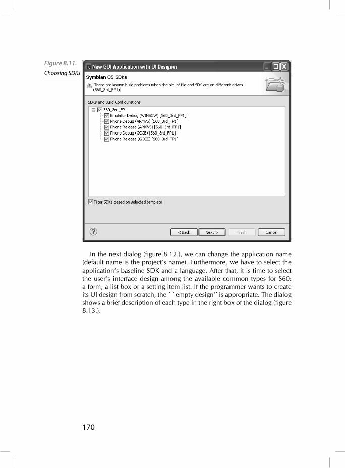
170
In the next dialog (fi gure 8.12.), we can change the application name (default name is the project’s name). Furthermore, we have to select the application’s baseline SDK and a language. After that, it is time to select the user’s interface design among the available common types for S60: a form, a list box or a setting item list. If the programmer wants to create its UI design from scratch, the ``empty design’’ is appropriate. The dialog shows a brief description of each type in the right box of the dialog (fi gure 8.13.).
Figure 8.11. Choosing SDKs

171
Now, we have to select the type of container among several values. If the programmer does not know exactly which parameters are suitable for its design, it is recommended to use the default value and CCoeControl class as the base container (Figure 8.14.).
Figure 8.12. Application’s
name, language and
baseline SDK
Figure 8.13. Choosing UI
design

172
The last dialog will ask for the UID for the application, the text for the copyright information and the author’s name. Finally, the wizard will show the project Directories information, that is where the generated source fi les, data fi les, etc. are going to be stored.
With this information, Carbide generates the project’s initial source and starts the UI Design Editor.
Figure 8.14. Choosing the type of container. Default value CCoeControl call is recommended}
Figure 8.15. UID, copyright and the author’s name
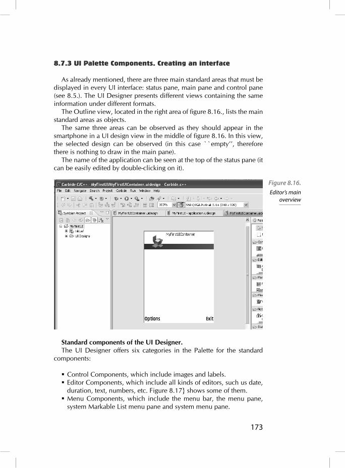
173
8.7.3 UI Palette Components. Creating an interface
As already mentioned, there are three main standard areas that must be displayed in every UI interface: status pane, main pane and control pane (see 8.5.). The UI Designer presents different views containing the same information under different formats.
The Outline view, located in the right area of fi gure 8.16., lists the main standard areas as objects.
The same three areas can be observed as they should appear in the smartphone in a UI design view in the middle of fi gure 8.16. In this view, the selected design can be observed (in this case ``empty’’, therefore there is nothing to draw in the main pane).
The name of the application can be seen at the top of the status pane (it can be easily edited by double-clicking on it).
Standard components of the UI Designer.The UI Designer offers six categories in the Palette for the standard
components:
Control Components, which include images and labels. Editor Components, which include all kinds of editors, such us date, duration, text, numbers, etc. Figure 8.17} shows some of them.
Menu Components, which include the menu bar, the menu pane, system Markable List menu pane and system menu pane.
Figure 8.16. Editor’s main
overview

174
Miscellaneous Components, which just offer a web client component that can be used for different purposes. See the Carbide.c++ and Nokia forum for more information.
Notes and dialogs Components, which include several kinds of query dialogs and notes.
Status and control Components, which include context icon, naviga-tion panels for image, text and volume.
Now, we are going to learn how to add standard components to a UI Design. All of the objects can be found in the Palette, as described above. Double-click on the Editors list to display all the available Editors as shown in fi gure 8.17. . Choose the proper one, for instance time Editor and drag it to the Design area. Resize the object if it is necessary. The properties view, at the bottom of the Carbide application, allow us to change the properties of the objects placed in the design area.
As soon as an object is added to the design, the UI Designer automati-cally generates its code. Obviously, this code contains the basic UI navi-gation; therefore, it is the programmer’s responsibility to write the rest of the code.
Other objects can be easily dragged from the Palette.
Figure 8.17. Editor components’ Palette
175
Nonlayout components of the UI DesignerThere are some components that are not always visible, that is they
are just visible under certain circumstances. Menus and dialog boxes are straightforward examples because they must be displayed just when the user interacts with them. Under this category, there are other components that do not have an UI, for example a WebClient component. There are some components that are not always visible, that is, they are just visible under certain circumstances. Menus and dialog boxes are straightforward examples because they must be displayed just when the user interact with them. Under this category, there are other components that do not have an UI, for example a WebClient component. There are some com-ponents that are not always visible, that is, they are just visible under cer-tain circumstances. Menus and dialog boxes are straightforward examples because they must be displayed just when the user interact with them. Under this category, there are other components that do not have a UI, for example a WebClient component.
Now, the question is: How can these components be used in the UI Designer if they are not visible? The UI Editor lets us manage and modify these components in the non-layout display, which is shown below the canvas. Let us see an example.
In order to add a new Menu Bar, go to PaletteMenuMenu Bar and drag it to the canvas area (Figure 8.18.). Notice that this component can-not be relocated or resized. Moreover, if we click in another part of the canvas, the Menu Bar disappears from the canvas. The component will appear again after clicking in the component shown in non-layout display. Like in the case of other components, its properties can be edited in the Properties view.

176
8.7.4 Properties and events
As seen before, the UI Designer makes it possible to edit several proper-ties of a component in the properties window. This graphical edition sim-plifi es the programmer’s work by letting us specify aspects and properties hard to remember for a programmer: there are a lot of components and every component has different properties; therefore a programmer would need to remember or to search for information about every component. Finally, the UI Designer will automatically generate the corresponding code. Furthermore, UI Designer makes it easier to set the position prop-erties of components. When coding manually, the programmer should take care about the size and relative position of each object. By using UI Designer, the programmer just has to select the object and place it directly in the canvas. After that, objects can be easily relocated, resized, etc.
Finally, UI Designer provides an Event Specifi cation window which facilitates the design of the objects’ events. This window may not be vis-ible the fi rst time the UI Designer is started. To open this window just go to windowshow viewother. There, search events and double-click on the event icon.
Figure 8.18. A non-layout Example

177
Through this window, programmers can specify which event is associ-ated with an object and assign the specifi c function to be called when this event occurs. Again, the UI Designer will generate the code including the functions. The behaviour of these functions should be completed later by the programmer.
8.7.5 Working with multiple designs
Previously, we have seen how to design a UI, adding components, editing properties, setting events, etc. All of the objects have been set into a single view, which can be understood as a set of objects within a view.
At the beginning of this chapter, a project has been created, and a sin-gle view has been related to this project. New views can be created and added to an existing project by selecting File New (or click the ``new'' icon), and choose ``S60 UI Design'' from the dialog box. Then, choose the project in the next dialog. Now, follow the steps as it has been seen before for a single view.
Finally, UI Designer will create a new view with its corresponding set of interface areas: status, main and control panes (and the corresponding code and fi les). You can choose the working view in the Symbian Project Navigator Window shown in fi gure 8.18.
When an application has more than one screen, it is necessary to set which one is the initial default view (see CaknViewAppUi class, to understand more about multiple views). In order to set the default initial view, just go to the UI Designs view, as fi gure 15 shows, and choose the desired default value.
Figure 8.18. Choosing the
default view

178
8.7.6 How is the code created?
The UI Designer generates a code, but unfortunately this code is just a skeleton of the whole code based on the standard S60 framework: a main UI which contains a view. This view contains the standard objects, multiple views and so on.
This code is syntactically correct at any time (can be built and run at any time), but essentially, it does nothing particular because there is no behaviour defi ned within the objects.
Therefore, this code must be extended in order to add the behaviour of each part. For this reason, it is necessary to understand how the UI auto-gen-erates the code each time a modifi cation is done (a new object is created, etc.). In this way, the UI Designer takes into account the following issues:
Creation of the interface. For each view’s container, the UI must generate the code needed to create the interface objects controlled with that view. This code must be located inside a function called by the container’s ContructL().
Defi nition of the class function. The UI defi nes every function and places them in the appropriate fi le.
Responses to interface events. The UI generates the code correspon-ding to events such as pressing a key; however, it is the programme-r’s duty to write the behaviour within these events.
Destroying the interface. The UI also generates the code that takes care of shutting down the interface and destroys the instances of clas-ses that manipulate it.
As mentioned above, the generated code must be fi lled in, and that is the programmer’s responsibility. The UI Designer can be used to add the cor-responding code, especially in event-driven functions. For that purpose, it is necessary to display the Events view (located at the bottom of the Cardbide.c application). If the Events view is not displayed, it can be evoked by going to the Windows menu, then selecting Show View and there, other. In this new dialog box choose ``Events’’, inside the display folder of Carbide.c++.
Now, every time we select an object, the Events view will show all the events that might be generated for that object. Then, the programmer can add handlers just clicking in the function cell.
8.7.7 More UI Designer features}
There are some features that are important for a UI interface but are not visible for the fi nal user. Programmers might consider these features in order to adapt their designs to different smartphones.

179
First of all, the programmer should consider the Screen resolutions. S60 Devices can be found under a wide variety of screen sizes and resolutions. The size and resolution can be easily be changed by means of the Palette fi ltering located in the top area of the Carbide.c++. The icon looks like a painter’s palette.
Another important visual aspect is the fact that views can be grouped forming a tab group, that is a set of views grouped and shown as tabs dis-played at the top of the smartphone screen.
UI Designer makes it possible to add a new view to the tab group by means of the “application.uidesign” view. In this view, select ``UI Designs’’ tab in order to force UI Designer to generate the corresponding code to display the tab group (see fi gure 8.20).
8.8 Data Persistence
It is usual that a Symbian Application requires the storage of data which will be useful in future executions of this application. The Symbian OS offers several ways of storing and recovering data persistence; the designer should choose one of them according to the application requirements.
8.8.1 Design considerations
In order to implement the most suitable data persistence solution, the designer must take several design factors into account.
Figure 8.20 Enabling tab
views

180
A) How is data persistence perceived by the user? What You See Is What You Have (WYSIWYH) This happens when the application saves the data automatically as soon as the data is writtin by the user. In other words, there is no explicit ``save’’ but-ton, and therefore the application must save the data whenever it can be lost (the application is closed, the phone is switched off, etc.) or when the application considers convenient (every minute, etc.). This way, the saved data becomes the current version of the data transpa-rent to the user and next time the application is launched, the saved data must appear. Obviously, displaying a message like ``busy’’ or ``saving in progress’’ by the application is convenient. Furthermore, an ``undo’’ option is useful, which by means of a button or a com-mand provides a way of restoring the old data overwritten by the use-r’s mistake.
Explicit load/save. The opposite approach takes place when the user is responsible for storing the data. In this kind of applications, the user chooses when the data is loaded or saved by means of invoking func-tions to load or to save the data. The user must choose which persi-stent data is going to be loaded when the application is started up, and must save it before the application is closed. If the application is closing and the data has not been saved, the application should warm the user that this data will be lost, suggesting the user to save the data. Therefore, there is no need for an automatic update/save or ``undo’’ option.
B) Considering the nature of the data} Document – Some kind of applications operates with work fi les that must be loaded in their entirety. Then, the application changes these fi les in RAM and fi nally saves them again.This behaviour can be implemented in both patterns seen above: WYSIWYH or Explicit load/save.
Database – On the other hand, some kind of applications deals with a large volume of data which does not necessarily need to be loaded completely into memory at once. Under these circumstances, it is a good practice to try to structure and classify the data in fragments which can be individually loaded, managed and updated using DBMS (DataBase Management System) techniques. An example of this kind of applications would be a calendar application. Unfortuna-tely, the UI framework does not implement explicit support for this data persistence; however, it can be done using the DBMS manage-ment systems of the Symbian OS.

181
A) Number of documentsSome applications just need one document to store data; therefore, the
user is not aware of the fi le selected by the application. Other applications give the user the freedom to choose the working fi le; however, there is a limitation in Symbian: an application can handle just one document opened at a time.
The UI framework has been designed for applications with a single default document, but it can be overridden in order to allow the user to choose the working fi le.
B) Possible use cases
The designer must consider how the application is going to be used. During the execution of the application, there can occur several pos-
sible use cases that must be taken into account in the data persistence schedule design.
How is the application going to be launched? For instance, from the shell application, automatically when the user wants to open a type of documents, etc.
How are the documents going to be opened? A kind of document can be opened by different applications; therefore, each type of docu-ment may be associated with an application. This association can be done by means of the UID value stored at the head of each fi le. Another way is to use a recognizer which shall be used to detect the MIME type which is attached to a fi le. Then, if a recognized type of fi le is selected, the OS would be able to launch the adequate appli-cation automatically.
Sometimes the user tries to open a document when the associated application is already running. In these cases, the application shall switch to handle the requested document.
Finally, the designer shall consider the fact that some applications can be launched as an application embedded within another appli-cation.
8.8.2 Storing– Externalizing
Figure 8.21. shows the relationship amongst the main classes involved in the storing task.
First of all, CeiKAppUi class offers methods which are used to han-dle several aspects of an application user interface such as opening and closing fi les as well as exiting the application cleanly. It is highly rec-ommended for every GUI application to use its own class derived from CeiKAppUi.

182
SetDocChanged method is used to inform that the document in use has been modifi ed. Therefore, your application is responsi-ble for calling setDocChanged, which should call the document’s CeiKDocument::SetChanged method in order to set the ‘Has changed’ document’s fl ag.SaveAnyChanged method is a cover function that can be used to
save any change made to the document associated to the application. This method calls SaveL method but this action can be done only if the ‘Has changed’ document’s fl ag is true. Finally, SaveL method will call CeiKDocument::SaveL to save the application UI’s associated document. In case the application UI is embedded, this method just sets the document as changed.SaveL method is used to save the document’s state when the UI frame-
work wants to close down the application. The parameter is used to indi-cate the reason, for instance low RAM, or the disk space is running out. Your application should override this function when you want to consider special cases (denoted by the parameter provided).
virtual IMPORT_C void SaveL(MSaveObserver::TSaveType aSaveType);
Then, it should call CeikProcess::SaveToDirectFileStoreL in order to save the document (or it can be optionally saved to a new fi le). SaveToDirectFileStoreL calls CeiKDocument::StoreL(),
which has to be fully implemented by the application’s programmer.
Figure 8.21. UiKon Architecture: Main classes used in the storing task
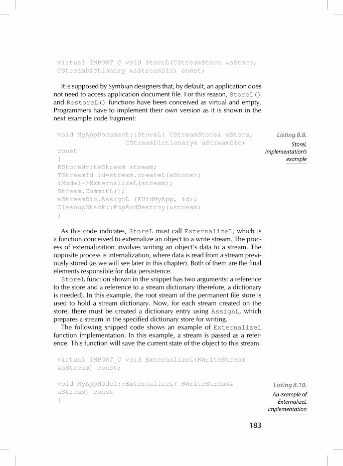
183
virtual IMPORT_C void StoreL(CStreamStore &aStore, CStreamDictionary &aStreamDic) const;
It is supposed by Symbian designers that, by default, an application does not need to access application document fi le. For this reason, StoreL() and RestoreL() functions have been conceived as virtual and empty. Programmers have to implement their own version as it is shown in the next example code fragment:
void MyAppDocument::StoreL( CStreamStore& aStore, CStreamDictionary& aStreamDic) const{RStoreWriteStream stream;TStreamId id=stream.createL(aStore);iModel->ExternalizeL(stream);Stream.CommitL();aStreamDic.AssignL (KUidMyApp, id);CleanupStack::PopAndDestroy(&stream)}
As this code indicates, StoreL must call ExternalizeL, which is a function conceived to externalize an object to a write stream. The proc-ess of externalization involves writing an object’s data to a stream. The opposite process is internalization, where data is read from a stream previ-ously stored (as we will see later in this chapter). Both of them are the fi nal elements responsible for data persistence.StoreL function shown in the snippet has two arguments: a reference
to the store and a reference to a stream dictionary (therefore, a dictionary is needed). In this example, the root stream of the permanent fi le store is used to hold a stream dictionary. Now, for each stream created on the store, there must be created a dictionary entry using AssignL, which prepares a stream in the specifi ed dictionary store for writing.
The following snipped code shows an example of ExternalizeL function implementation. In this example, a stream is passed as a refer-ence. This function will save the current state of the object to this stream.
virtual IMPORT_C void ExternalizeL(RWriteStream &aStream) const;
void MyAppModel::ExternalizeL( RWriteStream& aStream) const{
Listing 8.8. StoreL
implementation’s example
Listing 8.10. An example of
ExternalizeL implementation

184
aStream.WriteInt32L(iData1);aStream.WriteInt8L(iData2);//.....//Store as many objects as needed. //Take care of the order}
In this example the data is stored as TInt32 in the stream using one method from RwriteStream (there are a good variety of methods to save different kinds of data in RwriteStream class).
The object is responsible for serializing the objects that it owns calling externalizeL as many times as needed. Programmers must be aware of the fact that, when storing multiple data items in the stream in a specifi c order (externalizing), the restoring code will read the objects from the stream (internalizing), and must therefore follow exactly the same order which was used to externalize them.ExternalizeL function passes a stream as a reference in which the
data will be saved. For this task, RwriteStream class provides a wide variety of methods that can be used to write different types of data in a stream (WriteInt16L(), WriteInt32L(), WriteInt8L(), Wri-teReal32L(), WriteReal64L(), etc.)
8.8.3 Restoring– Internalizing
Now, it is time to deal with the restoring phase: fi gure 8.22. shows the classes involved in restoring and their relationship.
Figure 8.22. UiKon Architecture: Main classes used in the restoring task

185
CEikonEnv is an environment class provided by UIKON and derived from CConEnv. This class offers a set of useful functions for creating controls and functions for manipulating them. ConstructAppFrom-CommandLine is a CeiKonEnv’s member function used to initialize an application, consisting of a CEikAppUi, a CEikApplication, and a CEikDocument object.IMPORT_C void ConstructAppFromCommandLineL(const
TApaApplicationFactory &aApplicationFactory, const CApaCommandLine &aCommandLine);
As mentioned before, CeiKAppUi class offers methods for handling fi le opening and document restoring in an application user interface. ProcessCommandParametersL processes shell commands. It
is called by the Uikon application framework when an application is launched by the user opening a fi le from the shell or when a Create new fi le command is issued. This method will be explained in more detail in the start-up sequence section.CEikAppUi::OpenFileL() is a virtual function used to open a spe-
cifi c fi le. The implementation is empty, therefore it must be implemented by the programmer. The implemented code should take into account if there is a document already opened. In this case, it should be closed before opening the new one calling CEikDocument::OpenFile. This method is used to restore the document’s state from the specifi ed fi le, or to create a new default document.
In order to open and initialize a new fi le, the empty function CekAppUi::NewDocumentL shall be implemented.
During the opening phase, CeikDocument::OpenFile must inter-nalize the data (previously stored-externalized) by means of RestoreL. This function must be responsible for loading the application’s persisted data. However, RestoreL is a virtual and empty function, therefore it must be implemented as we will see in an example code.
Finally, CeikDocument::OpenFile should call CEIkProcess::SetMainDocFilename function in order to set the fi le store that stores the main document or should call CEIkProcess::SetMainStore in order to set the store that stores the main document.
As mentioned before, in order to restore the previously stored data, it is necessary for the application to over-ride the virtual function RestoreL (declared in CeikDocument). This virtual function is empty because the data persistence scheme is not implemented by default.
The following code snippet shows a RestoreL implementation exam-ple. Remember that RestoreL must recover the data exactly as it was in the document after it had been stored.

186
void MyAppDocument::RestoreL(const CStreamStore& aStore, const CStreamDictionary& aStreamDic) {ResetModelL();RStoreReadStream stream;TStreamId streamId=aStreamDic.At(KUidMyApp);stream.OpenLC(aStore, streamId);InternalizeL(stream);SetChanged(EFalse);CleanupStack::PopAndDestroy(&stream)}
This code calls to ExternalizeL, which should recover all the data contained within the stream. An example of ExternalizeL code is shown in the following code:
void MyAppModel::InternalizeL( RReadStream& aStream) {TInt data32 = aStream. ReadInt32L();Tint data8 = aStream. ReadInt8L();//.....//Restore as many objects as previously stored. //Mind the order}
InternalizeL function passes a stream as a reference where the data has been saved. For this task, RReadStream class provides a wide variety of methods that can be used to read different types of data from a stream ReadInt16L(), ReadInt32L(), ReadInt8L(), Read-Real32L(), ReadReal64L(), etc.)
8.8.4 Start-up sequence
In this section, we are going to see the sequence of events that happens when an application is started and it loads the associated document. Fig-ure 8.23. shows an overview of this sequence.
Listing 8.11. An example of RestoreL implementation
Listing 8.12. An example of InternalizeL implementation

187
The fi rst function called is CeikonEnv::ConstructAppFromCommandLineL(), which is used to construct a new application consisting of a CEikAppUi, a CEikApplication, and a CEikDocument.
Once the new application is started, CeikAppUi::ProcessCommandParametersL() function is used to establish the appropriate fi le-path and to check the availability of the document.
This function is overloaded and can be used as a one-parameter, two-parameter or three-parameter function. In the starting sequence, the one-parameter overload should call the three-parameter overload, and this last should call the two-parameter overload.
Then, the two-parameter overload will call the document’s Open-FileL function, which is used to restore a document’s state from the specifi ed fi le, or to create a new default document.OpenFileL function should restore the index of streams by means of
internalizing the stream dictionary. Remember that the index is contained in the root stream of the document fi le. After that, RestoreL function must be called.
Finally, as we have seen before, RestoreL is responsible for internal-izing the objects, that is it must call internalizeL, taking care of the order and kind of data in the streams.
8.8.5 Alternative Approaches
In section 8.8.1., we have seen that, depending on the nature of the data, it can be saved/recovered using an alternative approach to fi le stores using databases. The UI framework does not implement an explicit sup-port for this data persistence; however, we can deploy our own database alternative approach using the DBMS management systems of the Sym-bian OS.
Figure 8.22. UiKon
Architecture: a start-up sequence

188
A detailed description of this approach is out of the scope of this book; however, here are some tips that should help:
First of all, the Symbian OS provides SQLite (SQL server) that will be useful for this purpose.
In this approach, we do not need the StoreL/RestoreL functions; therefore, we do not need to overload them because they are virtual empty functions.
It is a good idea to override CeikAppUi methods (ProcessCom-mandParametersL()) trying to avoid unnecessary activities in order to minimize the start-up process.
Finally, programmers must design their own data persistence strategy according to the applications’ requirements.

189
Endnotes
1 The information in this book will refer to version 2.5.0 of Carbide.c++, the latest release available at the time of writing.
2 http://forum.nokia.com/3 http://www.eclipse.org/4 http://www.symbiansigned.com/5 http://forum.nokia.com/6 The cleanup stack is a structure used in Symbian to make sure that
objects in the heap are freed properly in case a leave (a Symbian exception) happens. See chapter 4