Embed Size (px)
Citation preview
Programming in Pro/ENGINEER Wildfire
Interactive graphical programming is carried in Pro/E at two different levels.
At the higher level, C++ program are supported through Pro/ENGINEER API Toolkit.
At lower level, a micro programming environment, Pro/E PROGRAM Tool, is supported.
These programming environments serve different needs.
It is very typical for a CAD system to support at least these two levels of interactive graphics programming.
Pro/ENGINEER API Toolkit
Pro/ENGINEER API Toolkit allows customers to extend, automate, and customize a wide range of Pro/ENGINEER design-through-manufacturing functionality. Pro/ENGINEER API Toolkit consists of a library of functions:
an application-programming interface (API), written in the C programming language. These functions are typically used by MIS organizations to create applications that run in parallel with Pro/ENGINEER and to integrate product information with the customer's corporate MRP/ERP systems. applications used extensively by companies participating in PTC's Cooperative Software Partner (CSP) program to interface their commercial information management products with Pro/INTRALINK. Normally, participation of a three day tutorial on the API Toolkit is needed to get the API Toolkit function module.
Typical Toolkit Applications
The extensive Pro/ENGINEER API Toolkit provides programmatic access for creating, interrogating, and manipulating almost every aspect of the engineering model and its data management.
automating the creation of complex features
automating the production of Pro/ENGINEER deliverables, such as BOMs, drawings, and manufacturing operations
improving product quality by performing design rule verification based on inputs from an external, knowledge-based system.
Specific Pro/ENGINEER API Toolkit Function
Customization of the Pro/ENGINEER-Foundation menusystem
Datum, solid, and manufacturing feature creation
Assemblies
Drawing automation
Access to model geometry
Pro/INTRALINK Access
The Pro/E API Toolkit provides complete access to the information within the Pro/INTRALINK environment, allowing customers to further leverage the product information contained within Pro/INTRALINK.
Specifically, this functionality allows:
Integration with MRP/ERP Systems
Custom client applications, such as Web integrated clients
Triggered verification, notification and enforcement of business process actions
Use of Pro/E API Toolkit
Product Capabilities:Create automated, single-use or derived designs by geometric and parametric constraintsExtend the Pro/ENGINEER user interface with custom processes seamlessly embedded in the interface Customize the Pro/ENGINEER menu system Collaborate between Pro/ENGINEER applicationsAccess peer-to-peer communications for better application diagnoses
Customer Benefits:Integrate expert systems and knowledge-based applications into the Pro/ENGINEER environment. Improve product quality with design rule verificationbased on inputs from an external, knowledge-based systems.
Pro/E Program Tool Pro/E Program Tool (Micro)(Micro)
The Pro/E Program environment, on the other hand, support quick and relatively straightforward interactive graphical programming in Pro/E for every users.
The programming environment is simply Pro/E and Microsoft Notepad or Word.
One can enter the Pro/E PROGRAM environment, by clicking Tools > Program… from the pull-down menu in the Pro/E PART or ASSEMBLY mode.
To show or edit the program, one can click Show Design or Edit Design from the PROGRAM menu.
A Typical Pro/E PROGRAM Routine
Any of the followings:Input variablesRelationsIF-ELSE clausesLists of all the features, and partsINTERACT statementsMASSPROP statement
After the Pro/E PROGRAM routine is edited, the user will be asked whether the changes are to be incorporated (in the message window at the bottom). To proceed, enter Y. If N entered, the program will not be executed and changes will be lost.
Input Variables
The INPUT statement must define the name and type of the variable. Variable names must always begin with a character. The following variable types are supported:
Number
String: This enables the user to enter parameters or model names.
Logical (YES_NO): Enter either Y or N.
An example:
INPUTTHICKNESS NUMBER"Enter wall thickness for the cylinder" END INPUT
Relations
All valid relations in a Pro/ENGINEER model can be entered in a Pro/PROGRAM.
An example:
d0 = d6 * 2
Here, d0 and d6 are dimension ID name.
IF-ELSE Clauses
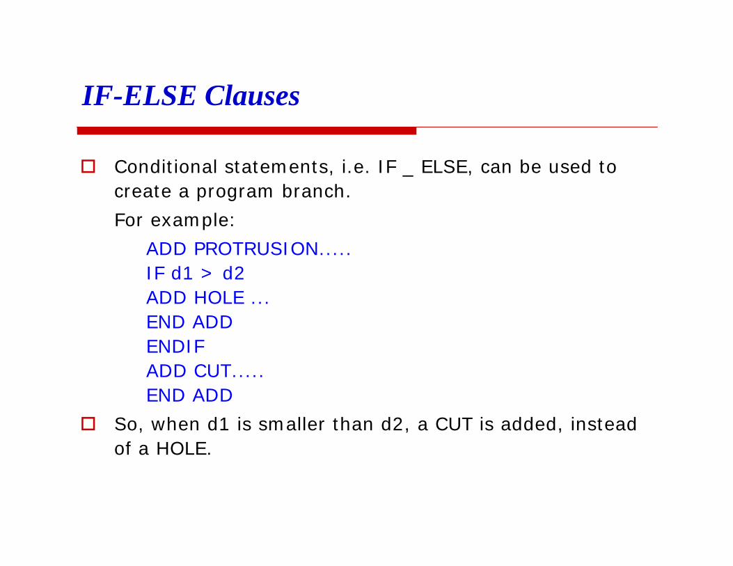
Conditional statements, i.e. IF _ ELSE, can be used to create a program branch.
For example:
ADD PROTRUSION..... IF d1 > d2 ADD HOLE ...END ADDENDIF ADD CUT..... END ADD
So, when d1 is smaller than d2, a CUT is added, instead of a HOLE.
Lists of Features and Parts
The program that Pro/E PROGRAM brings up simply includes all feature building commands used in creating the model and the properties of these features.
All features and parts are listed in the program.
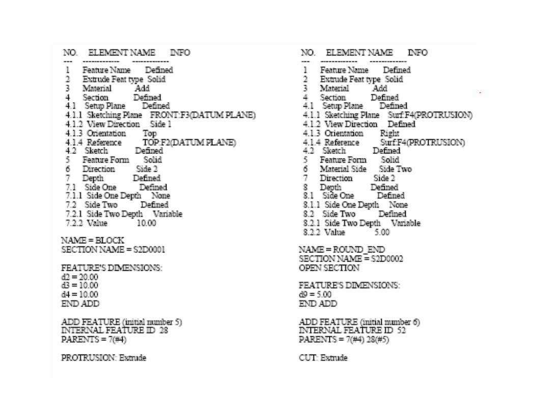
For instance, the ADD feature by EXTRUSION operation is recorded as:
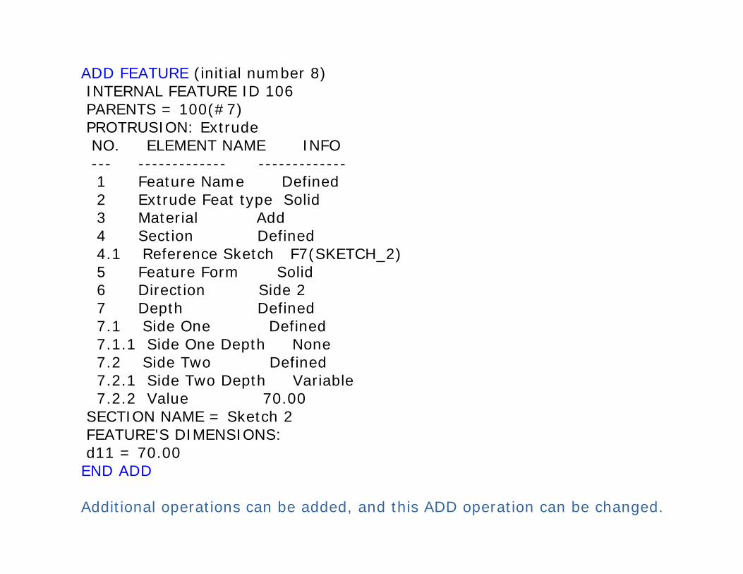
ADD FEATURE (initial number 8)INTERNAL FEATURE ID 106PARENTS = 100(#7) PROTRUSION: ExtrudeNO. ELEMENT NAME INFO --- ------------- -------------1 Feature Name Defined 2 Extrude Feat type Solid 3 Material Add 4 Section Defined 4.1 Reference Sketch F7(SKETCH_2) 5 Feature Form Solid 6 Direction Side 2 7 Depth Defined 7.1 Side One Defined 7.1.1 Side One Depth None 7.2 Side Two Defined 7.2.1 Side Two Depth Variable 7.2.2 Value 70.00
SECTION NAME = Sketch 2 FEATURE'S DIMENSIONS:d11 = 70.00
END ADD
Additional operations can be added, and this ADD operation can be changed.
INTERACT
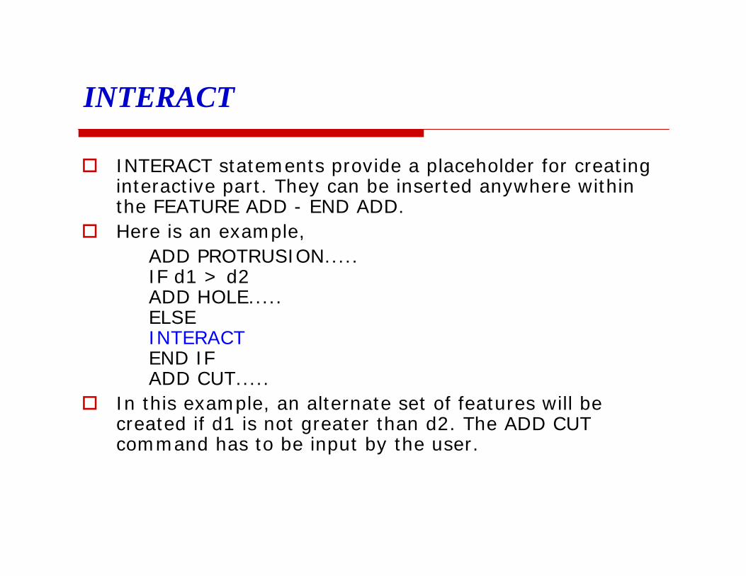
INTERACT statements provide a placeholder for creating interactive part. They can be inserted anywhere within the FEATURE ADD - END ADD.Here is an example,
ADD PROTRUSION..... IF d1 > d2 ADD HOLE..... ELSE INTERACTEND IF ADD CUT.....
In this example, an alternate set of features will be created if d1 is not greater than d2. The ADD CUT command has to be input by the user.
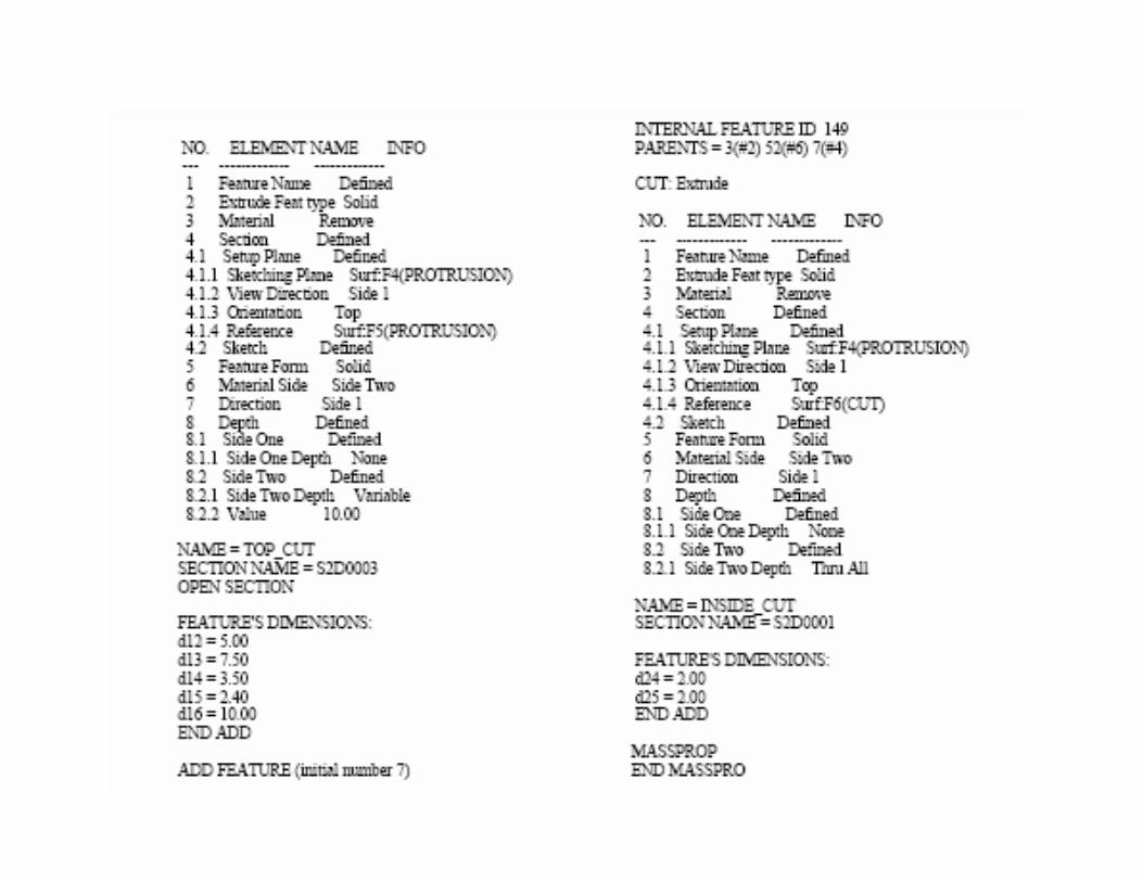
MASSPROP
The MASSPROP statement is used to update mass properties each time geometry changes. Format is as follows:
MASSPROP END MASSPROP
Other Operations for Feature Editing
Changing feature dimension
The dimensions of features in the program can be updated by a DIMENSION statement with:
MODIFY d# = value
Editing Errors
Common editing errors include:
Having an IF statement without an END IF statement or vice versa
Typing a variable name incorrectly in a relation or a condition
Reordering a child before the parent
Deleting a parent feature
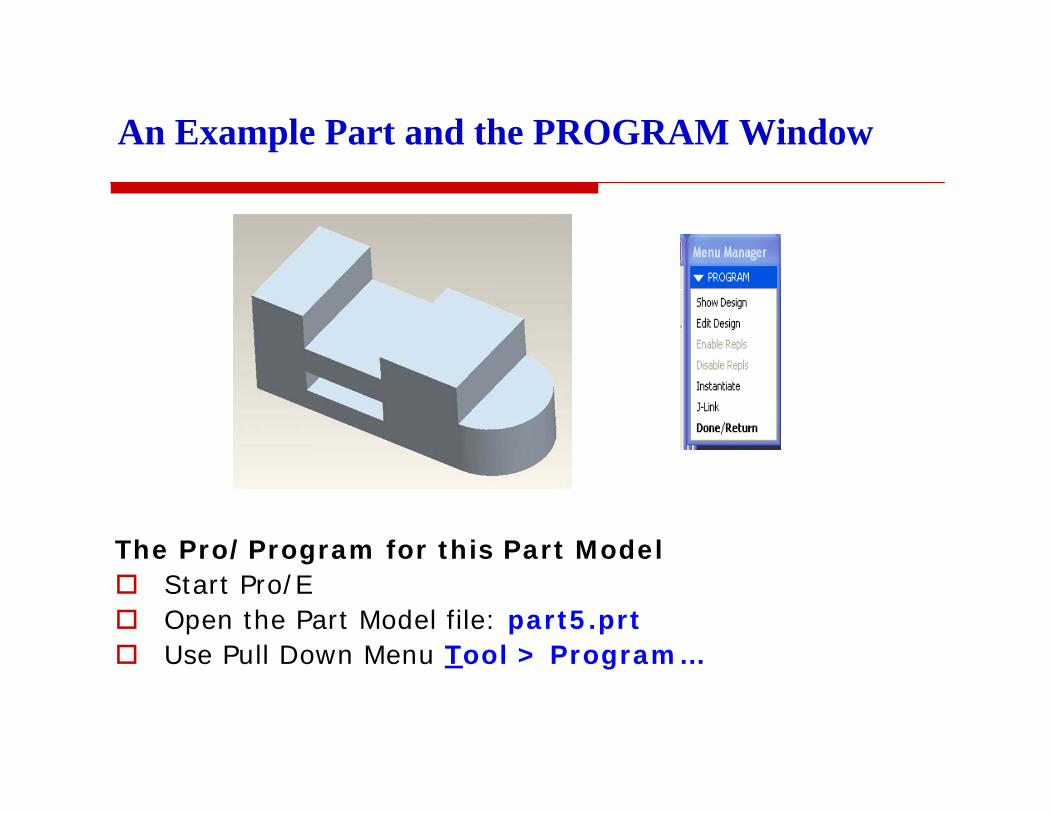
An Example Part and the PROGRAM Window
The Pro/Program for this Part ModelStart Pro/EOpen the Part Model file: part5.prtUse Pull Down Menu Tool > Program…
In the PROGRAM WindowShow Design and Edit Design options will display the Pro/Program that is used to create the displayed part model. Edit Design option allows you make changes to the model through “Programming Logic” rather than through “drawing and modeling”. Automated tasks can be achieved. If you exit from the Edit window and answer “Yes” in the message window at the bottom of the screen to the prompt: “Do you want to incorporate your changes into the model?” The programmed change will be added to the existing model. You can start from a simple template model to write various programs.The J-Link function allows you to load in Java codes.
An Example Part and the PROGRAM Window
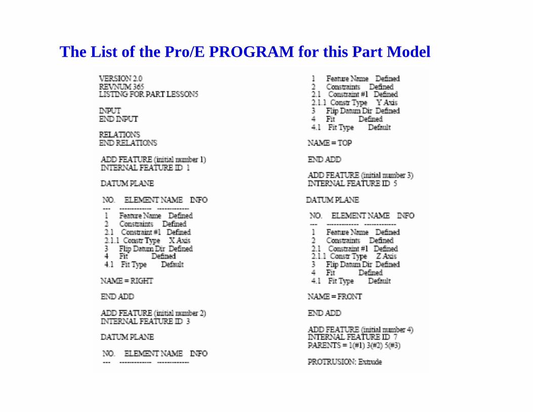
The List of the Pro/E PROGRAM for this Part Model
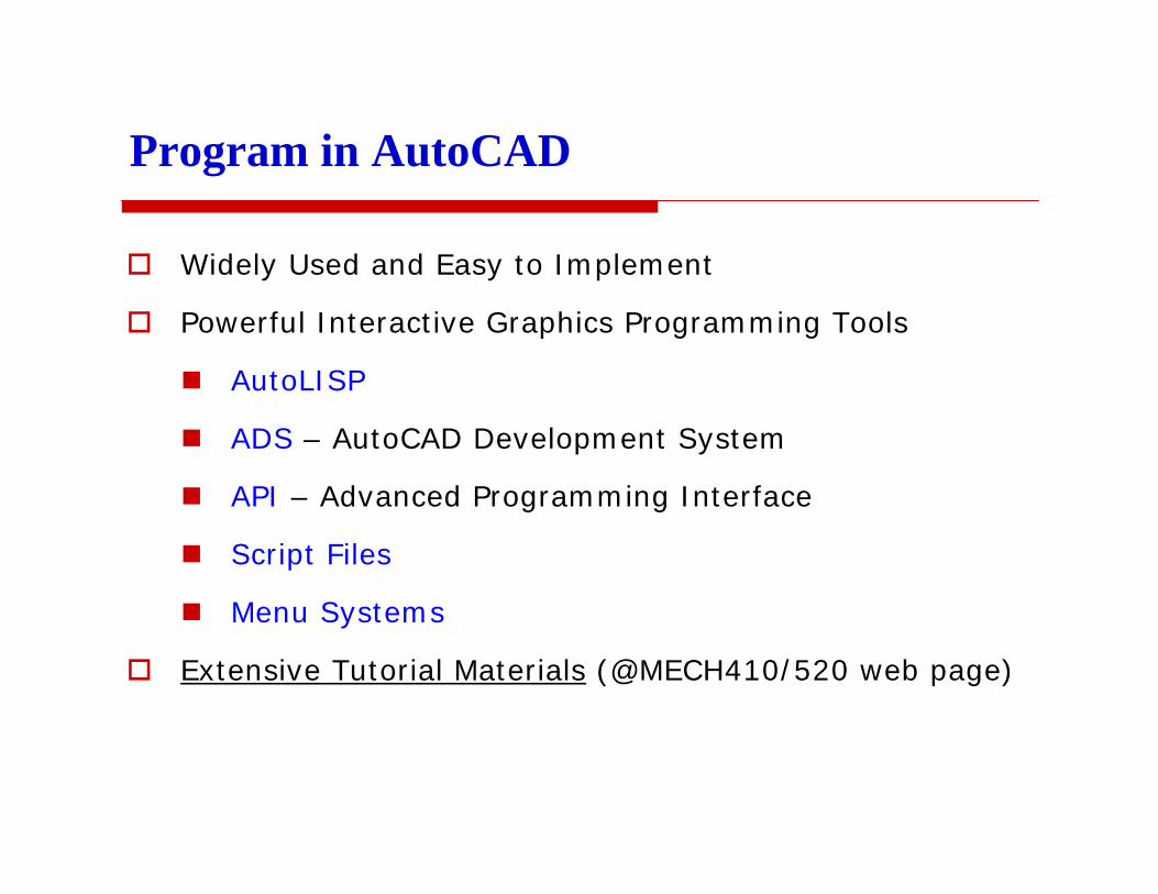
Program in AutoCAD
Widely Used and Easy to Implement
Powerful Interactive Graphics Programming Tools
AutoLISP
ADS – AutoCAD Development System
API – Advanced Programming Interface
Script Files
Menu Systems
Extensive Tutorial Materials (@MECH410/520 web page)
Summary
Interactive Graphics Programming is traditionally carried out using graphics routines in a special package.
Today all CAD systems offer different levels of Interactive Graphics Programming capabilities.
This unique capability of CAD systems allows their to be further developed into most convenient and more productive design tools.
Customization
User interface improvement (menu, etc.)
Repetitive and complex tasks
Guidelines for design
It is essential not to limit one’s capability of using CAD system simply as a modeling program or drafting tool.