Embed Size (px)
Citation preview

Programming Instructions
©
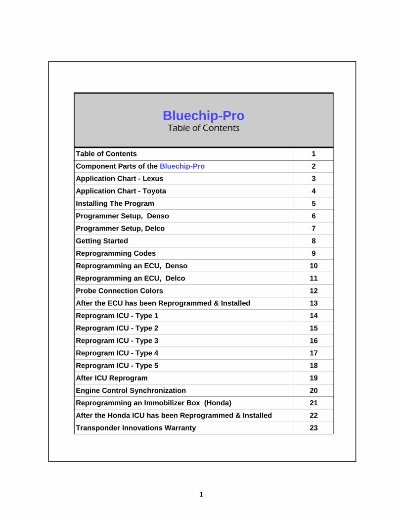
Table of Contents 1 Component Parts of the Bluechip-Pro 2 Application Chart - Lexus 3 Application Chart - Toyota 4 Installing The Program 5 Programmer Setup, Denso 6 Programmer Setup, Delco 7 Getting Started 8 Reprogramming Codes 9 Reprogramming an ECU, Denso 10 Reprogramming an ECU, Delco 11 Probe Connection Colors 12 After the ECU has been Reprogrammed & Installed 13 Reprogram ICU - Type 1 14 Reprogram ICU - Type 2 15 Reprogram ICU - Type 3 16 Reprogram ICU - Type 4 17 Reprogram ICU - Type 5 18 After ICU Reprogram 19 Engine Control Synchronization 20 Reprogramming an Immobilizer Box (Honda) 21 After the Honda ICU has been Reprogrammed & Installed 22 Transponder Innovations Warranty 23
Bluechip-Pro Table of Contents
1
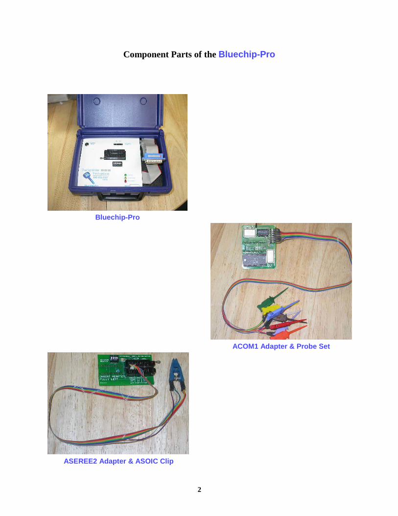
Component Parts of the Bluechip-Pro
2
Bluechip-Pro
ACOM1 Adapter & Probe Set
ASEREE2 Adapter & ASOIC Clip
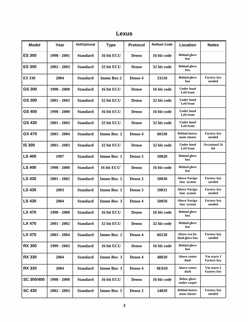
Model Year Std/Optional Type Protocol Reflash Code Location Notes
ES 300 1998 - 2001 Standard 16 bit ECU Denso 16 bit code Behind glove box
ES 300 2002 - 2003 Standard 32 bit ECU Denso 32 bit code Behind glove box
ES 330 2004 Standard Immo Box 2 Denso 4 33110 Behind glove box
Factory key needed
GS 300 1998 - 2000 Standard 16 bit ECU Denso 16 bit code Under hood Left front
GS 300 2001 - 2003 Standard 32 bit ECU Denso 32 bit code Under hood Left front
GS 400 1998 - 2000 Standard 16 bit ECU Denso 16 bit code Under hood Left front
GS 430 2001 - 2003 Standard 32 bit ECU Denso 32 bit code Under hood Left front
GX 470 2003 - 2004 Standard Immo Box 2 Denso 4 60330 Behind instru-ment cluster
Factory key needed
IS 300 2001 - 2003 Standard 32 bit ECU Denso 32 bit code Under hood Left front
Occasional 16 bit
LS 400 1997 Standard Immo Box 1 Denso 3 50020 Behind glove box
LS 400 1998 - 2000 Standard 16 bit ECU` Denso 16 bit code Behind glove box
LS 430 2001 - 2002 Standard Immo Box 5 Denso 3 50030 Above Naviga-tion system
Factory key needed
LS 430 2003 Standard Immo Box 5 Denso 3 50031 Above Naviga-tion system
Factory key needed
LS 430 2004 Standard Immo Box 3 Denso 4 50050 Above Naviga-tion system
Factory key needed
LX 470 1998 - 2000 Standard 16 bit ECU Denso 16 bit code Behind glove box
LX 470 2001 - 2002 Standard 32 bit ECU Denso 32 bit code Behind glove box
LX 470 2003 - 2004 Standard Immo Box 2 Denso 4 60230 Above ecu be-hind glove box
Factory key needed
RX 300 1999 - 2003 Standard 16 bit ECU Denso 16 bit code Behind glove box
RX 330 2004 Standard Immo Box 3 Denso 4 48020 Above center dash
Vin starts J Factory key
RX 330 2004 Standard Immo Box 3 Denso 4 0E010 Above center dash
Vin starts 2 Factory key
SC 300/400 1998 - 2000 Standard 16 bit ECU Denso 16 bit code Below glove under carpet
SC 430 2002 - 2003 Standard Immo Box 5 Denso 3 24020 Behind instru-ment cluster
Factory key needed
Lexus
3
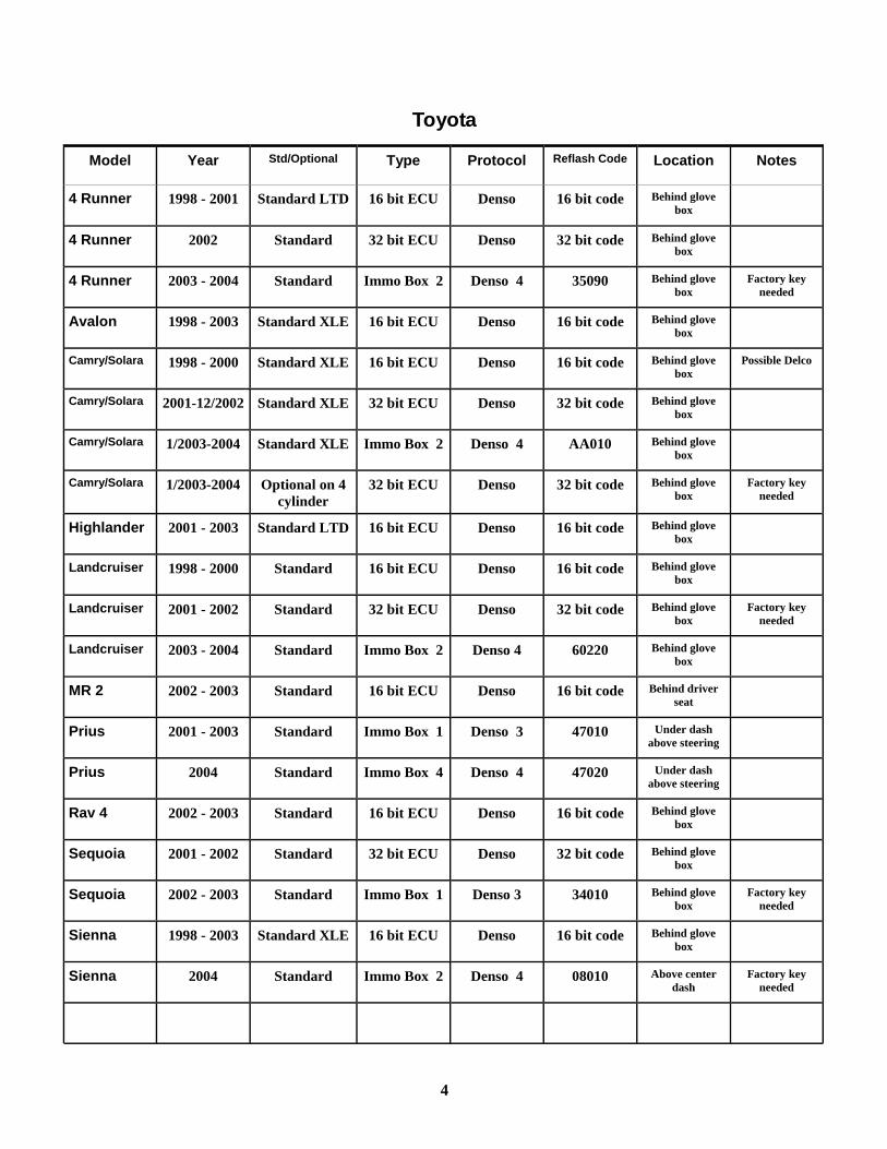
Model Year Std/Optional Type Protocol Reflash Code Location Notes
4 Runner 1998 - 2001 Standard LTD 16 bit ECU Denso 16 bit code Behind glove box
4 Runner 2002 Standard 32 bit ECU Denso 32 bit code Behind glove box
4 Runner 2003 - 2004 Standard Immo Box 2 Denso 4 35090 Behind glove box
Factory key needed
Avalon 1998 - 2003 Standard XLE 16 bit ECU Denso 16 bit code Behind glove box
Camry/Solara 1998 - 2000 Standard XLE 16 bit ECU Denso 16 bit code Behind glove box
Possible Delco
Camry/Solara 2001-12/2002 Standard XLE 32 bit ECU Denso 32 bit code Behind glove box
Camry/Solara 1/2003-2004 Standard XLE Immo Box 2 Denso 4 AA010 Behind glove box
Camry/Solara 1/2003-2004 Optional on 4 cylinder
32 bit ECU Denso 32 bit code Behind glove box
Factory key needed
Highlander 2001 - 2003 Standard LTD 16 bit ECU Denso 16 bit code Behind glove box
Landcruiser 1998 - 2000 Standard 16 bit ECU Denso 16 bit code Behind glove box
Landcruiser 2001 - 2002 Standard 32 bit ECU Denso 32 bit code Behind glove box
Factory key needed
Landcruiser 2003 - 2004 Standard Immo Box 2 Denso 4 60220 Behind glove box
MR 2 2002 - 2003 Standard 16 bit ECU Denso 16 bit code Behind driver seat
Prius 2001 - 2003 Standard Immo Box 1 Denso 3 47010 Under dash above steering
Prius 2004 Standard Immo Box 4 Denso 4 47020 Under dash above steering
Rav 4 2002 - 2003 Standard 16 bit ECU Denso 16 bit code Behind glove box
Sequoia 2001 - 2002 Standard 32 bit ECU Denso 32 bit code Behind glove box
Sequoia 2002 - 2003 Standard Immo Box 1 Denso 3 34010 Behind glove box
Factory key needed
Sienna 1998 - 2003 Standard XLE 16 bit ECU Denso 16 bit code Behind glove box
Sienna 2004 Standard Immo Box 2 Denso 4 08010 Above center dash
Factory key needed
Toyota
4
INSTALLING THE PROGRAM ON YOUR HARD DRIVE
SETTING UP THE PROGRAM TO RUN UNDER WINDOWS 1. Run: Instal1.bat from the Distribution Disk. This will create a directory called EPROM. 2. Click START, go to PROGRAMS, click WINDOWS EXPLORER. 3. Double click the EPROM folder, Right click WINPEP. 4. Click PROPERTIES. 5. Click on the PROGRAM tab. 6. Type "Bluechip-Pro Programmer " (or any name you prefer) on the line. 7. On the line marked CMD. Line type: C:\EPROM\WINPEP.BAT 8. At the bottom check the box marked "close on exit" 9. Click on the MEMORY tab, set EMS (expanded memory) to 16384 10. Click on the SCREEN tab, set usage to FULL 11. Click OK 12. Close WINDOWS EXPLORER
ADDING THE Bluechip-Pro PROGRAM TO YOUR START MENU 1. Click START, choose SETTINGS, click TASKBAR 2. Click START MENU PROGRAMS tab, click the ADD button 3. Create Shortcut appears, Type: C:\EPROM\WINPEP.BAT and press ENTER 4. Click 'next' 5. Click 'next' again 6. Click 'finish' 7. Click 'ok'
5
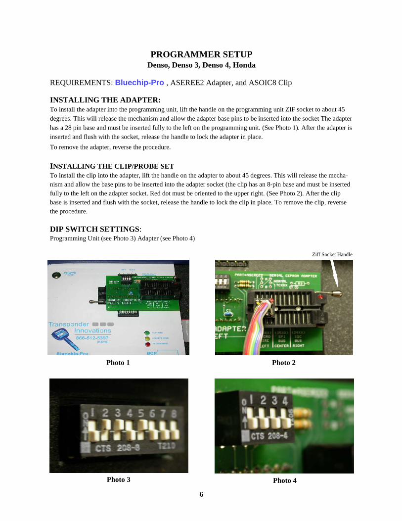
PROGRAMMER SETUP Denso, Denso 3, Denso 4, Honda
REQUIREMENTS: Bluechip-Pro , ASEREE2 Adapter, and ASOIC8 Clip INSTALLING THE ADAPTER: To install the adapter into the programming unit, lift the handle on the programming unit ZIF socket to about 45 degrees. This will release the mechanism and allow the adapter base pins to be inserted into the socket The adapter has a 28 pin base and must be inserted fully to the left on the programming unit. (See Photo 1). After the adapter is inserted and flush with the socket, release the handle to lock the adapter in place. To remove the adapter, reverse the procedure. INSTALLING THE CLIP/PROBE SET To install the clip into the adapter, lift the handle on the adapter to about 45 degrees. This will release the mecha-nism and allow the base pins to be inserted into the adapter socket (the clip has an 8-pin base and must be inserted fully to the left on the adapter socket. Red dot must be oriented to the upper right. (See Photo 2). After the clip base is inserted and flush with the socket, release the handle to lock the clip in place. To remove the clip, reverse the procedure.
DIP SWITCH SETTINGS: Programming Unit (see Photo 3) Adapter (see Photo 4)
Photo 1 Photo 2
Photo 3 Photo 4
6
Ziff Socket Handle
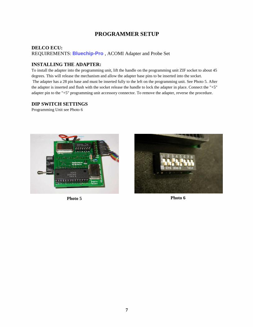
PROGRAMMER SETUP DELCO ECU: REQUIREMENTS: Bluechip-Pro , ACOMI Adapter and Probe Set INSTALLING THE ADAPTER: To install the adapter into the programming unit, lift the handle on the programming unit ZIF socket to about 45 degrees. This will release the mechanism and allow the adapter base pins to be inserted into the socket. The adapter has a 28 pin base and must be inserted fully to the left on the programming unit. See Photo 5. After the adapter is inserted and flush with the socket release the handle to lock the adapter in place. Connect the "+5" adapter pin to the "+5" programming unit accessory connector. To remove the adapter, reverse the procedure.
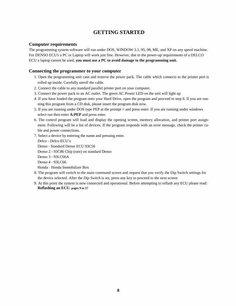
DIP SWITCH SETTINGS Programming Unit see Photo 6
Photo 5 Photo 6
7
GETTING STARTED
Computer requirements The programming system software will run under DOS, WINDOW 3.1, 95, 98, ME, and XP on any speed machine. For DENSO ECU's a PC or Laptop will work just fine. However, due to the power-up requirements of a DELCO ECU a laptop cannot be used, you must use a PC to avoid damage to the programming unit. Connecting the programmer to your computer
1. Open the programming unit case and remove the power pack. The cable which connects to the printer port is rolled up inside. Carefully unroll the cable.
2. Connect the cable to any standard parallel printer port on your computer. 3. Connect the power pack to an AC outlet. The green AC Power LED on the unit will light up 4. If you have loaded the program onto your Hard Drive, open the program and proceed to step 6. If you are run-
ning this program from a CD disk, please insert the program disk now. 5. If you are running under DOS type PEP at the prompt > and press enter. If you are running under windows
select run then enter A:PEP and press enter. 6. The control program will load and display the opening screen, memory allocation, and printer port assign-
ment. Following will be a list of devices. If the program responds with an error message, check the printer ca-ble and power connections.
7. Select a device by entering the name and pressing enter. Delco - Delco ECU’s Denso - Standard Denso ECU 93C56 Denso 2 - 93C86 Chip (rare) on standard Denso Denso 3 - 93LC66A Denso 4 - 93LC66 Honda - Honda Immobilizer Box
8. The program will switch to the main command screen and request that you verify the Dip Switch settings for the device selected. After the Dip Switch is set, press any key to proceed to the next screen
9. At this point the system is now connected and operational. Before attempting to reflash any ECU please read: Reflashing an ECU. pages 9 to 17
8
REPROGRAM CODES As with all reflash tools, this programmer cannot reprogram all Eproms with only one method. The Bluechip Pro Programmer is shipped with basic reflash codes that cover most applications. Please refer to the APPLICATION CHART pages 2 & 3 to be sure the proper code is used. You will be notified via email or telephone as to the avail-ability of updated codes. Also available are "pre-programmed" key files. These files allow you to reprogram an ECU with a code that matches an accompanying set of keys. Simply reflash the ECU with the proper file and cut the keys. No on board programming is needed, just "plug-n-go".
The Reprogram Codes that are shipped with this unit are:
1. DELCO - To be used only on ECU’s manufactured by Delco. 2. NONTRANS - To be used only when a non-transponder ECU manufactured by Denso has been reflashed
by mistake. 3. 16 BIT To be used on most Denso ECU’s manufactured from 1998-2001. (Please refer to APPLICATION
CHART). 4. 32 BIT To be used on most Denso ECU’s manufactured after 2001.
(Please refer to application chart) 5. Honda Reprogram 6. 60230 - Lexus, GX470, 2003 - 2004 7. 60330 - Lexus, GX470, 2003 - 2004 8. 50020 - Lexus, LS400, 1997 9. 50030 - Lexus, LS430, 2001 - 2002 10. 50031 - Lexus, LS430, 2003 11. 50050 - Lexus, LS430, 2004 12. 24020 - Lexus, SC430, 2002 - 2004 13. 48020 - RX330, 2004 14. 0E010 - RX330, 2004 15. 35090 - 4Runner, 2003 - 2004 16. AA010 - Camry, 2003 - 2004 17. AA010 - Solara, 2004 18. 60220 - Landcruiser, 2003 - 2004 19. 47010 - Prius, 2001 - 2003 20. 47020 - Prius, 2004 21. 08010 - Sienna, 2004 22. 34010 - Sequoia, 2003 - 2004 23. 33110 - Lexus, ES330, 2004
9
REPROGRAMMING A DENSO ECU 1. After removing ECU from vehicle, place it on a clean work surface. Remove the screws holding the cover in
place and set cover and screws aside. Remove screw (s) holding the circuit board in place and gently remove circuit board from ECU case.
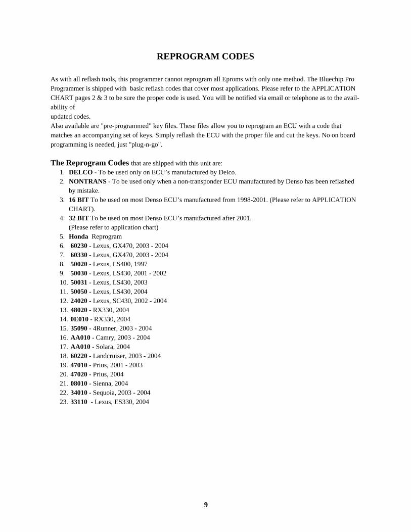
2. Locate the proper EPROM on the circuit board. The EPROM is identified on the chip itself with the markings (93c56) or (L56R). The EPROM is also identified with markings on the circuit board (IC900) or (IC499). See Photo 7
3. After the proper chip is located, use a small file or emery board to gently clean the protective coating off of the legs of the chip.
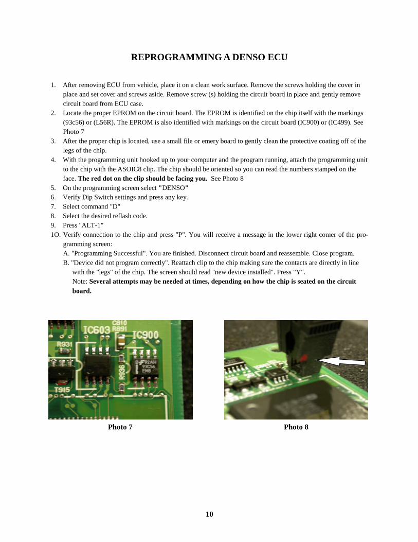
4. With the programming unit hooked up to your computer and the program running, attach the programming unit to the chip with the ASOIC8 clip. The chip should be oriented so you can read the numbers stamped on the face. The red dot on the clip should be facing you. See Photo 8
5. On the programming screen select "DENSO" 6. Verify Dip Switch settings and press any key. 7. Select command "D" 8. Select the desired reflash code. 9. Press "ALT-1" 1O. Verify connection to the chip and press "P". You will receive a message in the lower right comer of the pro-
gramming screen: A. "Programming Successful". You are finished. Disconnect circuit board and reassemble. Close program. B. "Device did not program correctly". Reattach clip to the chip making sure the contacts are directly in line
with the "legs" of the chip. The screen should read "new device installed". Press "Y". Note: Several attempts may be needed at times, depending on how the chip is seated on the circuit board.
Photo 7 Photo 8
10
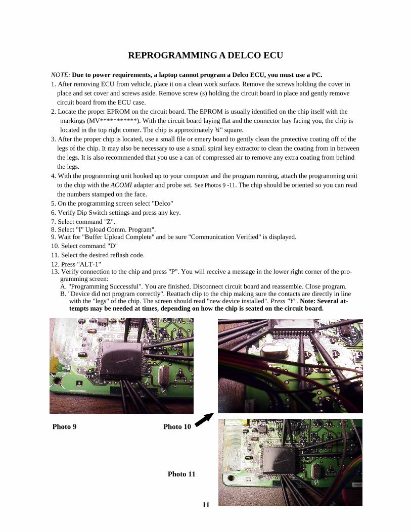
REPROGRAMMING A DELCO ECU NOTE: Due to power requirements, a laptop cannot program a Delco ECU, you must use a PC. 1. After removing ECU from vehicle, place it on a clean work surface. Remove the screws holding the cover in
place and set cover and screws aside. Remove screw (s) holding the circuit board in place and gently remove circuit board from the ECU case.
2. Locate the proper EPROM on the circuit board. The EPROM is usually identified on the chip itself with the markings (MV***********). With the circuit board laying flat and the connector bay facing you, the chip is located in the top right comer. The chip is approximately ¾" square.
3. After the proper chip is located, use a small file or emery board to gently clean the protective coating off of the legs of the chip. It may also be necessary to use a small spiral key extractor to clean the coating from in between the legs. It is also recommended that you use a can of compressed air to remove any extra coating from behind the legs.
4. With the programming unit hooked up to your computer and the program running, attach the programming unit to the chip with the ACOMI adapter and probe set. See Photos 9 -11. The chip should be oriented so you can read the numbers stamped on the face.
5. On the programming screen select "Delco" 6. Verify Dip Switch settings and press any key. 7. Select command "Z". 8. Select "I" Upload Comm. Program". 9. Wait for "Buffer Upload Complete" and be sure "Communication Verified" is displayed. 10. Select command "D" 11. Select the desired reflash code. 12. Press "ALT-1" 13. Verify connection to the chip and press "P". You will receive a message in the lower right corner of the pro-
gramming screen: A. "Programming Successful". You are finished. Disconnect circuit board and reassemble. Close program. B. "Device did not program correctly". Reattach clip to the chip making sure the contacts are directly in line
with the "legs" of the chip. The screen should read "new device installed". Press "Y". Note: Several at-tempts may be needed at times, depending on how the chip is seated on the circuit board.
Photo 9 Photo 10
Photo 11
11

Gray
Reset - Green Xmit - Orange Rcv - Brown
Red
Blue
Mod
A
Mod
B
Gnd
Yellow - 8ME
MC 68HC11E9
Violet
Probe Connection Colors
12
DELCO ECU EPROM CHIP
After the ECU has been Reprogrammed and Installed
Programming The Engine Control Module
Important Note: The ECU will be in “Automatic Registration Mode”, when you install it. Three (3) keys need to be pro-grammed in. The ECM can hold up to Ten (10) keys. While the ECU is in “Auto Registration Mode”, the last key registered becomes the valet key. It is important to register the valet key as the last key in the sequence. You can just program three (3) master keys if you want. The security light will blink until the first master key is inserted in the ignition.
1. Insert the first master transponder key into the ignition lock cylinder for registration. The security light should
remain “on”. Do not turn the key. Wait about 15 seconds. Remove the key from the ignition. 2. Insert the second master transponder key to be registered. The security light should remain “on”. Do not turn
the key. Wait about 15 seconds. Remove the key from the ignition. 3. Insert the third transponder key to be registered, The security light should go out after a couple of seconds. Do
not turn the key. Remove the key from the ignition. If the security light is still illuminated, pump the brake pedal 5 times to close the programming cycle.
4. When you are done registering keys, remove any key that might be in the ignition. 5. The cycle is now closed.
The programming mode will end after 10 more seconds.
13
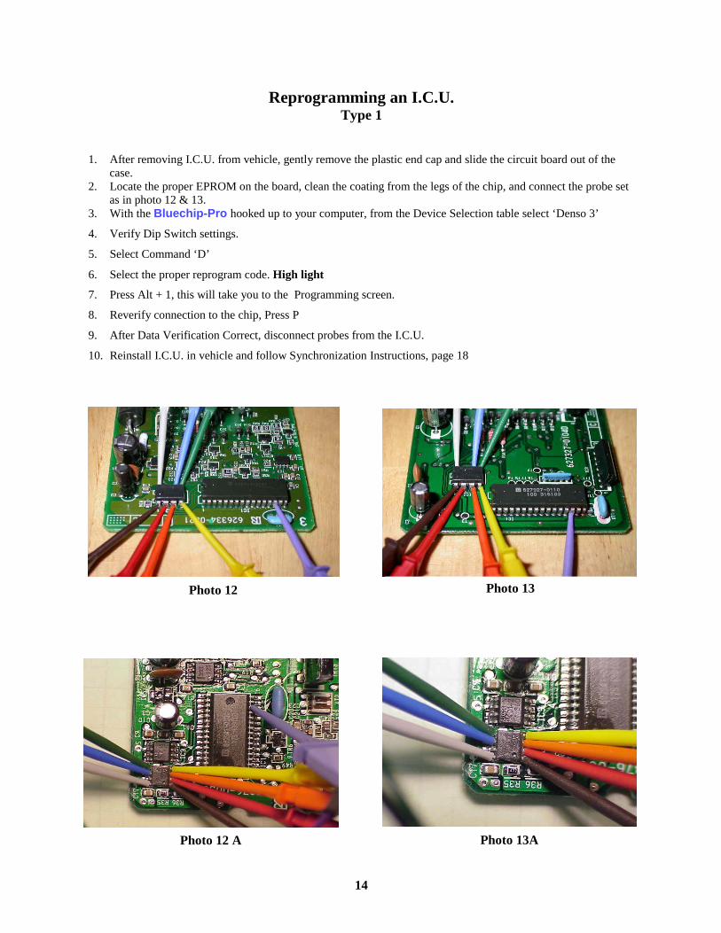
Reprogramming an I.C.U. Type 1
1. After removing I.C.U. from vehicle, gently remove the plastic end cap and slide the circuit board out of the
case. 2. Locate the proper EPROM on the board, clean the coating from the legs of the chip, and connect the probe set
as in photo 12 & 13. 3. With the Bluechip-Pro hooked up to your computer, from the Device Selection table select ‘Denso 3’
4. Verify Dip Switch settings.
5. Select Command ‘D’
6. Select the proper reprogram code. High light
7. Press Alt + 1, this will take you to the Programming screen.
8. Reverify connection to the chip, Press P
9. After Data Verification Correct, disconnect probes from the I.C.U.
10. Reinstall I.C.U. in vehicle and follow Synchronization Instructions, page 18
Photo 12 Photo 13
14
Photo 12 A Photo 13A
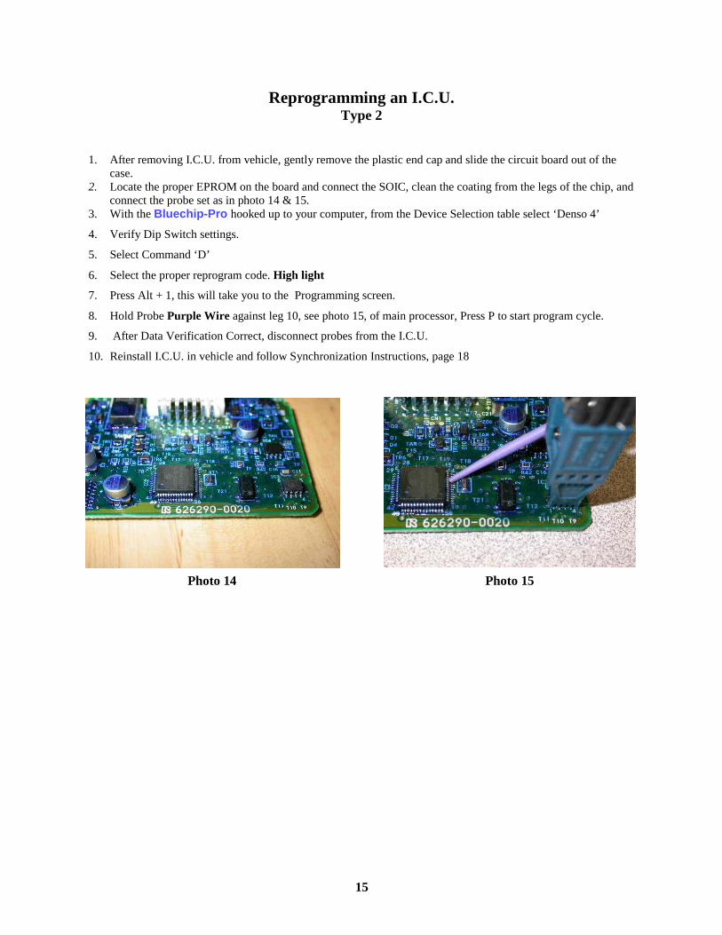
Reprogramming an I.C.U. Type 2
1. After removing I.C.U. from vehicle, gently remove the plastic end cap and slide the circuit board out of the
case. 2. Locate the proper EPROM on the board and connect the SOIC, clean the coating from the legs of the chip, and
connect the probe set as in photo 14 & 15. 3. With the Bluechip-Pro hooked up to your computer, from the Device Selection table select ‘Denso 4’
4. Verify Dip Switch settings.
5. Select Command ‘D’
6. Select the proper reprogram code. High light
7. Press Alt + 1, this will take you to the Programming screen.
8. Hold Probe Purple Wire against leg 10, see photo 15, of main processor, Press P to start program cycle.
9. After Data Verification Correct, disconnect probes from the I.C.U.
10. Reinstall I.C.U. in vehicle and follow Synchronization Instructions, page 18
Photo 14 Photo 15
15
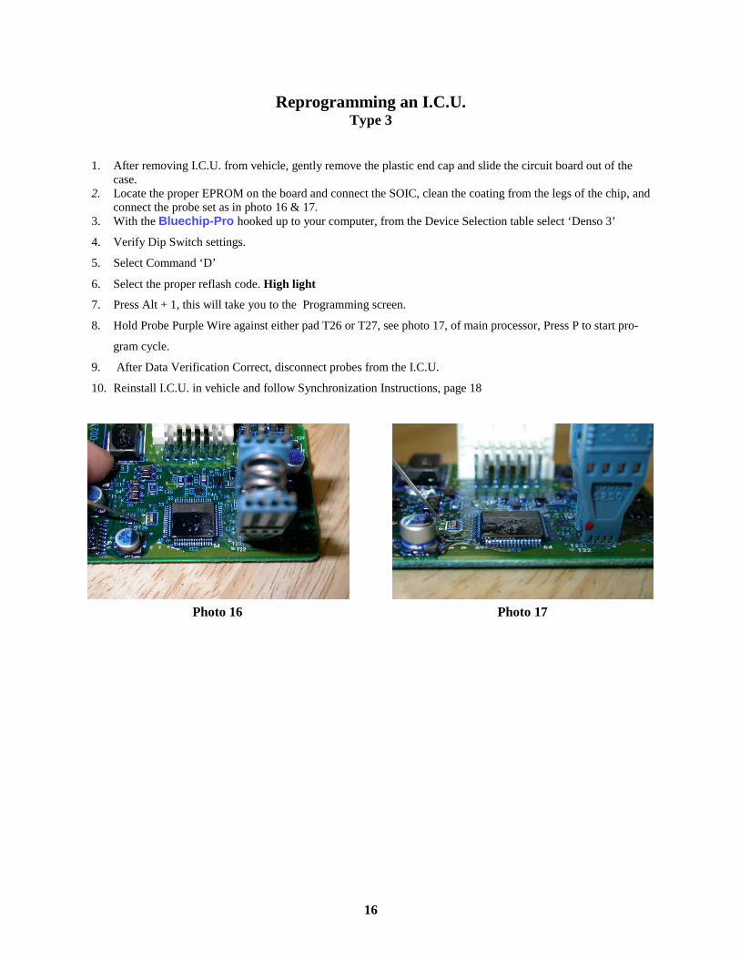
Reprogramming an I.C.U. Type 3
1. After removing I.C.U. from vehicle, gently remove the plastic end cap and slide the circuit board out of the
case. 2. Locate the proper EPROM on the board and connect the SOIC, clean the coating from the legs of the chip, and
connect the probe set as in photo 16 & 17. 3. With the Bluechip-Pro hooked up to your computer, from the Device Selection table select ‘Denso 3’
4. Verify Dip Switch settings.
5. Select Command ‘D’
6. Select the proper reflash code. High light
7. Press Alt + 1, this will take you to the Programming screen.
8. Hold Probe Purple Wire against either pad T26 or T27, see photo 17, of main processor, Press P to start pro-
gram cycle.
9. After Data Verification Correct, disconnect probes from the I.C.U.
10. Reinstall I.C.U. in vehicle and follow Synchronization Instructions, page 18
Photo 16 Photo 17
16
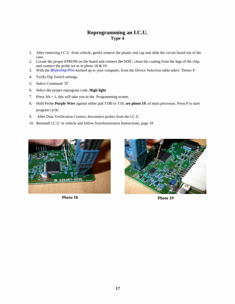
Reprogramming an I.C.U. Type 4
1. After removing I.C.U. from vehicle, gently remove the plastic end cap and slide the circuit board out of the
case. 2. Locate the proper EPROM on the board and connect the SOIC, clean the coating from the legs of the chip,
and connect the probe set as in photo 18 & 19. 3. With the Bluechip-Pro hooked up to your computer, from the Device Selection table select ‘Denso 4’
4. Verify Dip Switch settings.
5. Select Command ‘D’
6. Select the proper reprogram code. High light
7. Press Alt + 1, this will take you to the Programming screen.
8. Hold Probe Purple Wire against either pad T180 or T19, see photo 19, of main processor, Press P to start
program cycle.
9. After Data Verification Correct, disconnect probes from the I.C.U.
10. Reinstall I.C.U. in vehicle and follow Synchronization Instructions, page 18
Photo 18 Photo 19
17
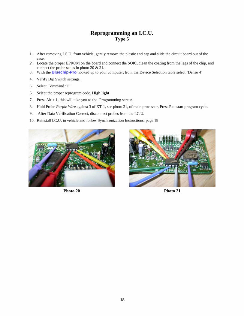
Reprogramming an I.C.U. Type 5
1. After removing I.C.U. from vehicle, gently remove the plastic end cap and slide the circuit board out of the
case. 2. Locate the proper EPROM on the board and connect the SOIC, clean the coating from the legs of the chip, and
connect the probe set as in photo 20 & 21. 3. With the Bluechip-Pro hooked up to your computer, from the Device Selection table select ‘Denso 4’
4. Verify Dip Switch settings.
5. Select Command ‘D’
6. Select the proper reprogram code. High light
7. Press Alt + 1, this will take you to the Programming screen.
8. Hold Probe Purple Wire against 3 of XT-1, see photo 21, of main processor, Press P to start program cycle.
9. After Data Verification Correct, disconnect probes from the I.C.U.
10. Reinstall I.C.U. in vehicle and follow Synchronization Instructions, page 18
Photo 20 Photo 21
18

After Lexus/Toyota ICU has been reprogrammed
Programming Procedure for Separate Immobilizer ECU
Once a new Immobilizer (transponder) ICU is installed, the Immobilizer (transponder) ICU is in Auto learn mode, this includes 2 Master & 1 Valet keys. If less than 3 keys are to be programmed, the Immobilizer (transponder) ICU Auto learn cycle must be closed manually. To close the Auto learn cycle; turn the ignition lock 5 times from OFF to ON in 10 sec-onds or less. Then remove the key. The Security (theft) light will stay ON with no key in the ignition when the Immobilizer (transponder) ICU is in the Auto learn mode. If the Security light blinks 2 times for a second and then 1 time for a quarter second, the Auto learn mode failed. If the Security light blinks 2 times for a quarter second and then 2 time for a second, a key that was al-ready learned was used again to learn.
© 1994-2003 National Auto Lock Service, Inc
Acknowledgement Our thanks to National Auto Lock Service, Inc. and Michael Hyde for permission to use the Copyright
AutoSmart 2003 information contained on pages 18 and 19 of this manual.
19

Engine Control Synchronize
After you replace the IMMOBILIZER CONTROL UNIT - You must perform the following
1. Insert an already learned Master key into the ignition lock and turn to the ON position.
2. Do not try to start the vehicle.
3. Use a suitable jumper (to short) the terminals on the OBD2 port for 30 minutes and then remove. The Engine Control Unit should then be resynchronized with the Immobilizer ICU.
4. Remove the key from the ignition and then reinsert to start the vehicle.
© 1994-2003 National Auto Lock Service, Inc
These terminals are also referred to as TC (13) & CG (4).
Terminal #4 is Orange in color, Terminal #13 is Pink w/Black in color.
20

Reprogramming an Immobilizer Box Honda
1. Open plastic cover on box by gently lifting the lid at the end nearest to the plug connectors.
2. Locate the proper EPROM on the circuit board. The EPROM is identified on the chip itself with the mark-ings, (93C46) or (L46AR) The chip is located at the top center of the circuit board. Nearest to the lid hinge.
3. After the proper chip is located, use a small file or emery board to gently clean the protective coating off of the “legs” of the chip.
4. With the programming unit hooked up to your computer and the program running, attach the programming unit to the chip with the ASOIC8 clip. (Denso) The chip should be oriented so you can read the numbers stamped on the face. The red dot on the clip should be facing you. See Photo 22
5. On the programming screen select “Honda”
6. Verify dip switch settings and press any key.
7. Select command D
8. Select Honda Reprogram.
9. Press Alt 1
10. Verify connection to the chip and press P. You will receive a message in the lower right hand corner of the programming screen:
A. Programming Successful. You are finished. Disconnect circuit board and reassemble. Close program.
B. Device not programmed correctly. Reattach clip to the chip making sure the contacts are directly in line with the legs of the chip. The screen should read, New device installed. Press Y.
Note: Several attempts may be needed at times, depending on how the chip is seated on the circuit board.
Photo 22
21

After Honda Reprogram 1. Reinstall ICU in vehicle
2. Cut blade (HD106) to match vehicle and attach to red key head.
3. Cut Master key (HD106 PT 5) to match vehicle. Key must be cloned from supplied key or originated on RW2 to sequence #31EE11A4 94CE7F20.
4. Program ICU and keys using a PGM (factory) Tester or suitable aftermarket tester (T Code, SDD, Code-seeker)
22
12 Month Limited Warranty - Bluechip-Pro Programming Unit Transponder Innovations, warrants to the original purchaser of this product that it will be free of manufacturing defects for a period of 12 months following the date of purchase. This warranty does not include damage to the prod-uct resulting from accident or misuse. This limited warranty is nontransferable, is contingent upon proper use of the products covered and does not cover products which have been modified or which have been subject to unusual physical or electrical stress. If the product becomes defective within the warranty period, we will elect to repair or replace it, provided it is delivered at the consumer's expense to Transponder Innovations with a valid Returns Materials Authorization (RMA) number. No product will be accepted for repair, replacement or return without a valid RMA number. An RMA number will be issued by calling Transponder Innovations, 1-866-512-5397 THERE ARE NO OTHER WARRANTIES, EXPRESSED OR IMPLIED, INCLUDING, BUT NOT LIMITED TO, THE IMPLIED WARRANTIES OF MERCHANTABILITY AND FITNESS FOR A PARTICULAR PURPOSE. Trans-ponder Innovations WILL NOT BE LIABLE FOR ANY SPECIAL, INDIRECT, INCIDENTAL OR CONSEQUEN-TIAL DAMAGES.
23