Embed Size (px)
Citation preview

ALLEN&HEATH iDR Training. Programming Module 1 Page - 1 - of 19 JAN08
iDR Training SET UP A NEW CONFIGURATION Programming Module 1
In three separate modules, we will build up a configuration (.CFG) program for an installation with two rooms – one with stereo audio and one with mono audio. There are two stereo sources, and each room will have remote control over source selection and level.

ALLEN&HEATH iDR Training. Programming Module 1 Page - 2 - of 19 JAN08
There are seven steps in this first module.
1. Open the default configuration and archive it under the new .CFG name
2. Assign comms ports
3. Assigns PL devices
4. Set up the power-up preset and add PL devices
5. Set stereo channels
6. Name channel strips
7. Clear the Routing Matrix

ALLEN&HEATH iDR Training. Programming Module 1 Page - 3 - of 19 JAN08
1. Open the default configuration a. Click the Open
Configuration icon. b. Use the drop down menu to
locate the iDR-8 sub-folder in Program Files.

ALLEN&HEATH iDR Training. Programming Module 1 Page - 4 - of 19 JAN08
c. Open the Default .CFG
ALLEN&HEATH iDR Training. Programming Module 1 Page - 5 - of 19 JAN08
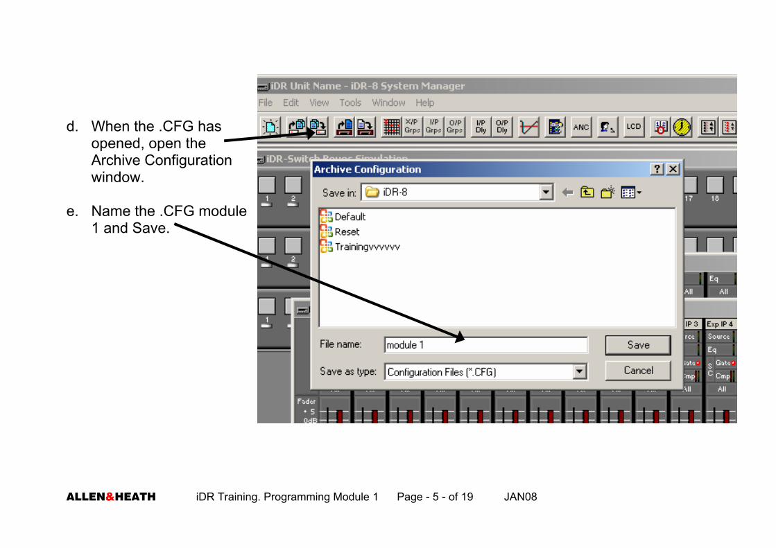
d. When the .CFG has
opened, open the Archive Configuration window.
e. Name the .CFG module
1 and Save.

ALLEN&HEATH iDR Training. Programming Module 1 Page - 6 - of 19 JAN08
2. Assign communication ports
The iDR network port is always active. The remaining ports – RS232, MIDI and PL-Anet need to be selected in the software to be activated. Only two of these ports can be active at any time.
a. From the File menu, select preferences.
b. Select Communications Options.

ALLEN&HEATH iDR Training. Programming Module 1 Page - 7 - of 19 JAN08
c. Select a suitable combination that includes PL-Anet. ☺ Archive configuration

ALLEN&HEATH iDR Training. Programming Module 1 Page - 8 - of 19 JAN08
3. Assign the number and type of PL devices a. Go back up to File – Preferences. b. Select PL Options.

ALLEN&HEATH iDR Training. Programming Module 1 Page - 9 - of 19 JAN08
c. Click PL Options and chose two PL-4. d. Click OK

ALLEN&HEATH iDR Training. Programming Module 1 Page - 10 - of 19 JAN08
e. You will now have a PL-4 Wall Plate Settings icon on the far left of the screen . . . . . . and two PL-4 Simulations on the far right of the screen. ☺ Archive configuration

ALLEN&HEATH iDR Training. Programming Module 1 Page - 11 - of 19 JAN08
4. Set up a power-up preset
If no preset is selected by the programmer, to be recalled on power-up, the unit will recall its default preset when powered-up. This default preset is unavailable to the programmer in normal use and can lead the inexperienced to believe that the unit has reverted to the factory default configuration. Since a configuration can only be loaded singly from a PC / laptop, this is not possible! All softkeys, soft LEDs and soft rotaries (including PL devices) must be programmed in the power up preset so that they are active and ready to use.

ALLEN&HEATH iDR Training. Programming Module 1 Page - 12 - of 19 JAN08
4.1 Set name of preset
a. Open the Preset Manager window. b. Note that the preset number is 1 and it
is checked to be recalled on power-up.

ALLEN&HEATH iDR Training. Programming Module 1 Page - 13 - of 19 JAN08
c. Name the preset Start and click Set name. ☺ Archive configuration.

ALLEN&HEATH iDR Training. Programming Module 1 Page - 14 - of 19 JAN08
4.2 Add PL-4 to preset a. Scroll down the Select devices
to add column and select PL-4 01.
b. Click Add.

ALLEN&HEATH iDR Training. Programming Module 1 Page - 15 - of 19 JAN08
c. Click Set All and OK. PL-4 01 is now added to the power up preset. d. Repeat this process to
add the second PL-4 02 to the preset.
☺ Archive configuration

ALLEN&HEATH iDR Training. Programming Module 1 Page - 16 - of 19 JAN08
5. Set stereo channels It is important to set stereo input and output channels before carrying out any routing. The reason for this is that once two channels are combined, the routing matrix graphic for the even numbered channel are no longer shown. An example would be where mono i/p channels 1 & 2 are routed to output 4. If at a later stage, it is decided to stereo i/p channels 1 & 2. Channel 2 graphic is now hidden in the routing matrix window ‘behind’ the graphic for channel 1. If the system design now changes and we un-route stereo channel 1/2 from o/p 4 and route it to o/p 5, audio will still be present at o/p 4 because the hidden i/p 2 routing will still be enabled. This is a good trouble shooting pointer – if a customer complains that they are hearing signal at an output where it is not wanted, it is likely that there is a stereo channel involved. The solution is to un-stereo the channels, correct the routing and then re-stereo the channels.

ALLEN&HEATH iDR Training. Programming Module 1 Page - 17 - of 19 JAN08
In our example, both sources, i/ps 1/2 & 3/4 are stereo, and one of our outputs, 1/2 is stereo. a. Select the Select Stereo Channels window. b. Set inputs 1&2, 3&4 and outputs 1&2 to stereo pairs and
click OK. c. Note the change in the channel strip numbers. ☺ Archive configuration

ALLEN&HEATH iDR Training. Programming Module 1 Page - 18 - of 19 JAN08
6. Name channels a. Double click on the channel write-on strip. b. Type in the desired channel name and click OK. c. Repeat this for the remaining channels:
• i/p 1/2 …CD • i/p 3/4 …DJ • o/p1/2 …Z1 (zone 1) • o/p 3 …..Z2
☺ Archive configuration

ALLEN&HEATH iDR Training. Programming Module 1 Page - 19 - of 19 JAN08
Conclusion We now have a new .CFG named Module 1 with the following attributes: • PL-Anet port active
• Two PL-4 and PL-5
• Preset 1 is set to be recalled on power up
• We have two stereo input channels for the CD player and the music feed from the DJ mixer.
• We have a stereo output to feed a room (zone 1) and a mono output to feed a second room
(zone 2).
In the next programming module, we will build on this .CFG and program a series of presets, each one of which will route the CD or DJ signals to either of the two rooms.