Embed Size (px)
Citation preview

CCS100 & CMS100 11001-1392-200704
TRAINING MANUAL
1
DICKEY-john TRAINING CONFERENCE HANDBOOK
Programming, Operating & Basic Repair Techniques
CCS100 Control System
CMS100 Monitoring System

TRAINING MANUAL
CCS100 & CMS100 11001-1392-2007042

CCS100 & CMS100 11001-1392-200704
TRAINING MANUAL
3
Table of Contents
Course Objectives ..........................................................................7
Lesson Materials ............................................................................9
Basic Functions of CCS/CMS Systems ......................................11
Overview of System Layout.................................................................. 13
Basic Modes of Operation .................................................................... 19
Developing Constants – Granular System .......................................... 29
Developing Constants – Liquid System .............................................. 33
Developing Constants – Anhydrous Ammonia .................................. 41
Technical Reference Material ............................................................... 47
Commonly Asked Questions ................................................................ 59
Granular Spreader Constant References ............................................ 67
Liquid Sprayer Constant References .................................................. 68
Anhydrous Ammonia Constant References ....................................... 69
Cable Repair Procedures ...................................................................... 70
Troubleshooting Sensors ..................................................................... 74

TRAINING MANUAL
CCS100 & CMS100 11001-1392-2007044

CCS100 & CMS100 11001-1392-200704
TRAINING MANUAL
5
WELCOME
DICKEY-john welcomes the opportunity to present this material. It is our pleasure to provide training on this equipment and to answer any concerns or questions. With this exchange of information, we can together perform our jobs better.
The main function of this workshop is to allow you to become more acquainted with these products. It is always a pleasure to serve you – our valued customers. DICKEY-john believes that the more understanding its customer’s have of a prod-uct, the more useful that product becomes.

TRAINING MANUAL
CCS100 & CMS100 11001-1392-2007046
CCS100 & CMS100 11001-1392-200704
TRAINING MANUAL
7
Course Objectives
The CCS/CMS100 system is an extremely versatile unit that can be easily programmed to automatically control the application rates of given products regardless of changes in vehicle ground speed and also monitor a number of fi eld conditions. The major purpose of this course is to train you in the operation, programming, and the performing of minor troubleshooting procedures on the CCS/CMS100 Control system. When you have completed this course, you will have learned how to:
Explain the basic function and use of each system.Explain the differences between and the functions of both units.Defi ne sensors required and explain the purpose of each.Defi ne the use of each touchswitch on the front panel.Enter the different modes and explain the function of each.Read and explain the meanings of displayed data.State the meaning of error messages and how to correct errors.Understand how to use the cabling diagrams.Perform basic repair by using simple troubleshooting charts.Secure aid in the event of a serious problem.
••••••••••

TRAINING MANUAL
CCS100 & CMS100 11001-1392-2007048

CCS100 & CMS100 11001-1392-200704
TRAINING MANUAL
9
Lesson Materials
This manual is divided into two separate parts. Part I contains instructional ma-terials to explain basic overall concepts and operating principles of the systems. Part II contains more detailed reference materials which elaborate certain sub-jects with more in-depth information. Other information is for reference material use later. Topics included in this Part are:
Lesson 1: Basic Function of CCS/CMS Systems.
Lesson 2: Overview of System Layout.
Lesson 3: Basic Modes of Operation.
Lesson 4: Developing Constants – Granular System.
Lesson 5: Developing Constants – Liquid System.
Lesson 6: Developing Constants – Anhydrous Ammonia.
Lesson 7: Common Operator Problems Encountered.
PART 1

TRAINING MANUAL
CCS100 & CMS100 11001-1392-20070410

CCS100 & CMS100 11001-1392-200704
TRAINING MANUAL
11
Basic Functions of CCS/CMS Systems
Topics:
1. Overall System Function2. Sensors Required and Options Available3. System Confi gurations
The CCS100 and CMS100 consoles units are both microprocessor controlled containing similar circuitry but performing different functions. The major difference between the units is designed into the internal program of the microprocessor. The operator must complete the programming process in the fi eld by entering a few constants upon which the microprocessor acts to calculate its performance. Once the two units are properly programmed, the system (both units) automati-cally controls (CCS100) the application rate of the product and also monitors (CMS100) speed and area information. Automatic application starts when the vehicle begins to move, varies as ground speed changes and stops when the vehicle ceases moving. The product application rate is controlled as long as the ground speed is within the specifi ed speed range of the system.
Function of the CCS Console
The CCS100 Custom Control System is a versatile device that can be installed as either a granular spreader, NH3 or liquid system. It can then be programmed to automatically control the application rate of a given product. That rate of ap-plication remains constant throughout the fi eld regardless of any changes in the vehicle ground speed.
Function of the CMS Console
The CMS100 Custom Monitoring System is a monitoring device that is usually in-stalled as a companion unit to the CCS100 system for displaying additional infor-mation. The unit utilizes the same sensor signals as the CCS100 console to de-velop status readouts. The additional information displayed is for ground speed, fi eld area, total area, area per hour, distance (footage counter), fi eld product, total product, product level, application rate, product sensor output, and an auxiliary sensor output. The CMS100 unit normally connects to a control system’s sensors through an addition of a “Y” cable which parallels the sensor input signals.
The CMS100 also can operate as a stand alone unit to monitor speed/area func-tions provided the CCS100 main harness and ground speed sensor are installed on the vehicle.
· The CMS100 console can be used alone to monitor speed/area provided the harness and sensors are available.
Three Basic Confi gurations
The two console units are installed in one of three basic confi gurations. The CMS100 unit is connected to each system via a Y-cable.
LESSON 1
The CCS and CMS units are often connected together into one control system. Sensors develop status signals which are delivered through cabling to the two consoles for processing and monitoring. Output drive signals from the CCS100 control the application rate of the product. Input signals to the CMS100 monitor operating conditions.
In this lesson, you will learn how to:
Defi ne the basic function of the CCS unit.Defi ne the basic function of the CMS unit.Use both units together in one systemConfi gure a basic granular spreader control system.Confi gure a liquid sprayer control system.Confi gure an anhydrous ammonia control system.
•
•
•
•
•
•

TRAINING MANUAL
CCS100 & CMS100 11001-1392-20070412
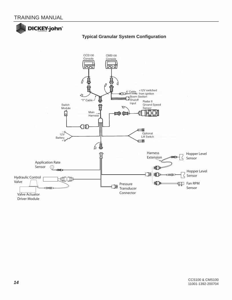
1. A Granular Spreader Control System consists of fi ve major compo-nents; (1) control console(s) with a switch module, (2) a hydraulic control valve and vale driver, (3) a ground speed sensor, (4) an application rate sensor, and (5) an optional hopper level sensor or fan sensor. The two consoles are installed within the vehicle cab. The hydraulic control vale is installed in the hydraulic line to the conveyor motor to regulate the motor rate. The ground speed sensor senses the miles per hour (MPH) speed of the vehicle. One of three types of ground speed sensors is installed; (1) in-line speedometer drive sensor, (2) magnetic wheel sensor, or (3) radar velocity sensor. The application rate sensor is installed on a shaft that rotates at a proportional rate to the conveyor speed.
2. A Liquid Sprayer Control System consists of only four major components; (1) control console(s) with a switch module, (2) liquid control valve, (3) ground speed sensor, and (4) a pressure sensor. The CCS100 console compares these input signals to a desired application rate as pro-grammed by the operator and develops a proper output drive signal to the servo control valve to maintain uniform application rate.
3. An Anhydrous Ammonia Control System consists of fi ve major compo-nents; (1) control console(s) with a switch module, (2) control valve, (3) fl ow-meter, (4) thermal transfer unit(s), and (5) a ground speed sensor. A vapor detector and implement switch may also be used. When installed on an Anhydrous Ammonia Applicator, the fl ow of the product varies au-tomatically in proportion to ground speed changes, keeping the applica-tion rate uniform throughout the fi eld.
Basic Cabling Harnesses
The CCS100 and CMS100 consoles are connected to the required group of sen-sors through cabling harnesses. These harnesses deliver the sensor input sig-nals to the consoles as well as return drive signals for controlling the application rate of the product. Several different sets of harnesses are employed depending upon the type of vehicle and the confi guration of the system involved (See Les-son 2).
Putting It Together:
The CCS100 console controls the application rate and the CMS100 console monitors speed/area func-tions.The two consoles use signals from the same sensors and are connect-ed in parallel to share those signals.The CCS100 console can be used interchangeably between a liquid sprayer system and an anhydrous ammonia system by changing one constant location.
•
•
•

CCS100 & CMS100 11001-1392-200704
TRAINING MANUAL
13
Overview of System Layout
Topics:
1. Harness Functions2. Granular System Harness Layout3. Liquid System Harness Layout4. CMS100 Confi gurations5. Extension Cable Use
Harness Confi gurations
In order to meet the needs of a number of applications and to remain versatile, a number of harnesses and extensions are available. Variations to any of these harness arrangements are made by adding extension cables to reach extended lengths. Also, three truck harness are available for use when only the CMS100 console is installed.
Lesson 2
The CCS100 and CMS100 units are connected to their sensors through cabling. The cables used and the number of sensors required are de-termined by the system specifi cations and the vehicle on which the system is installed.
In this lesson, you will learn how to:
Select cabling for a granular spreader system.Select cabling for a liquid sprayer system.Select cabling for an anhydrous am-monia system.Select cabling for specifi c CMS100 applications.
•
•
•
•
TRAINING MANUAL
CCS100 & CMS100 11001-1392-20070414
Typical Granular System Confi guration
Application RateSensor
Hydraulic ControlValve
Valve ActuatorDriver Module
HarnessExtension
Hopper LevelSensor
Hopper LevelSensor
o oFan RPMSensor
PressureTransducerConnector

CCS100 & CMS100 11001-1392-200704
TRAINING MANUAL
15
Typical Liquid System Confi guration for Pull Type Sprayer
Valve ActuatorDriver Module
ExtensionCable
ExtensionCable
ExtensionCable
ImplementHarness
PressureTransducer

TRAINING MANUAL
CCS100 & CMS100 11001-1392-20070416
Liquid System with Truck Harness Confi guration
Valve ActuatorDriver Module
ExtensionCable
ExtensionCable
PressureTransducer

CCS100 & CMS100 11001-1392-200704
TRAINING MANUAL
17
Typical Anhydrous Ammonia System Confi guration
Valve ActuatorDriver Module
ExtensionCable
ExtensionCable
ImplementHarness
Thermal TransferUnit
VaporDetector
FlowMeter
HardwareKit

TRAINING MANUAL
CCS100 & CMS100 11001-1392-20070418

CCS100 & CMS100 11001-1392-200704
TRAINING MANUAL
19
Basic Modes of Operation
Topics:
· Similarity Between CCS100 and CMS100 Units· Use of the Switch Module· Applying Power· Defi ning and Using the “OPERATE” Mode· Defi ning and Using the “SETUP” Mode· Defi nition of All Switches· Meaning of Display Panel Messages
Console Similarities
Both the CCS100 and CMS100 are very similar in appearance and basic opera-tion. Each unit has its own power switch, located to the right side, an LCD display for reading data, and three touchswitches to select and control the various func-tions of the system. Both the CCS100 and CMS100 consoles employ two basic modes of operations – OPERATE and SETUP. These two modes are controlled by the three touchswitches across the lower portion of the console front. Each touchswitch contains two legends. The supper legend identifi es the OPERATE mode and the lower legend identifi es the SETUP mode. The OPERATE mode selects normal fi eld operation and the SETUP mode allows for entering constants into memory which actually control the desired rate of product application. If you are familiarizing yourself for the fi rst time on installed equipment, simply make sure no product is loaded into the tank or hopper.
Turning On System Power
To turn power onto the system, switch the power switch to the ON position on the front (right side) of each console. Whenever power is turned on, both con-soles come up in the OPERATE mode, ready to go. It is important to note that the CMS100 also receives power through the vehicle ignition switch. If either the power switch or the ignition switch is off, the display indicates “OFF”.
Operating the System
Each time power is applied through the ignition switch and the power switch to each console, the alarm sounds briefl y and each display shows all display segments for approximately one second. For the next second, the programmed value for the application rate is displayed. If the CCS100 is in the P mode, the high and low speed and pressure ranges are also displayed. Following this, the CCS100 enters the OPERATE mode and displays the current application rate which remains zero until the vehicle begins to move to produce a ground speed. If the display on the CCS100 should show “OFF”, the OFF/AUTO/FLUSH switch on the switch module is in the AUTO position. Simply change it to OFF. The CMS100 also enters it’s OPERATE mode. If the display on the CMS100 shows “OFF”, either the power switch or the ignition switch is not turned on.
LESSON 3
When power is applied to the sys-tem, both the CCS100 and CMS100 units come up in the OPERATE mode ready to go. The OPERATE mode of the system is discussed in the lesson and the SETUP mode to enter constants is discussed in the next lesson.
In this lesson, you will learn how to:
Turn power on to both the CCS100 and the CMS100 console units.Use the Switch Module.Defi ne the function of the Basic “OPERATE” mode for both units.Defi ne the function of the Basic “SETUP” mode for both units.Defi ne the purpose of the con-stants for both the CCS100 and the CMS100.Enter Constants into the memory of both units.
•
••
•
•
•

TRAINING MANUAL
CCS100 & CMS100 11001-1392-20070420
Using the CCS100 Console in the OPERATE Mode
Once in the OPERATE mode, the display indicates pounds (or gallons for liquid system) per acre. The OPERATE mode touchswitches for “+” and “-“ increase or decrease the application rate by a specifi ed increment as programmed into memory. Anytime the application rate increments from the targeted rate, the dis-played value per acre fl ashes. If either the “+” or “-” touchswitches are depressed to change the application rate, the displayed value begins to fl ash. To return to the target application rate, depress the OPER touchswitch and the display stops fl ashing. Also note each valid touchswitch closure initiates a short tone burst from the alarm.
Using the Switch Module
The switch module functions in conjunction with the CCS100 console to control the product output of the system. A three position switch on the switch module overrides the output commands of the CCS100 unit. The OFF position provides a control valve shut-off command to the control console. The AUTO position allows the console automatic control of the system. In this position, the application rate is controlled by the ground speed. When the switch is held in the FLUSH posi-tion (spring loaded), the control valve is driven open to a predetermined fl ow rate. This action purges the system. In the SETUP mode, the switch module switch performs no function.
Using the CMS100 Console in the Operate Mode
Once in the OPERATE mode, a triangular shaped pointer near the upper or lower edge of the display points to the monitored function. The function’s current value is shown by the 6-digit display. Depressing the center touchswitch moves the pointer to the right. The current value for each monitored function is indicated on the display. By repeatedly depressing the center touchswitch (right pointing arrow), the pointer travels from left to right across the digital display. The left touchswitch (left pointing ar-row) performs the same function except in reverse order.
The right touchswitch (RESET) resets the following functions to zero when se-lected; (1) Field Area, (2) Total Area, (3) Field Product, (4) Total Product. It also serves to initialize or set Product Level to the programmed tank (or hopper) level full value. To reset, depress and hold the RESET touchswitch for approximately three seconds.
CCS100 Console with Switch Module

CCS100 & CMS100 11001-1392-200704
TRAINING MANUAL
21
Up to eleven functions are monitored by the CMS100 unit. Defi nitions for these functions are outlined below.
SPEED – Vehicle ground speed in MPH (kph).
FIELD AREA – Accumulated area in acres (hectares) the vehicle has covered since the last reset. This function keeps a daily record of the area covered. Up to 999999 acres (hectares) can be accumulated before the counter rolls over to zero. If the optional CCS100 implement switch is installed, accumulation occurs only when the spreader is engaged. When the switch module is in the OFF posi-tion, accumulation is also stopped. When the accumulation is inhibited, the check mark, on the lower left edge of the display, is displayed. Accumulated data is retained in memory when the console is turned off.
TOTAL AREA – Total accumulated area in acres (hectares) the vehicle has covered since the counter was last reset. This function operates the same as for Field Area above.
AREA/HR – Displays acres (hectares) per hour.
DISTANCE – Displays distance traveled in feet (or meters) the vehicle has trav-eled between the counter start and stop cycle. Up to 999999 feet (meters) can be accumulated before the counter rolls over to zero. The counter can be started and stopped by momentarily depressing the RESET touchswitch. Holding the RESET touchswitch depressed for approximately 3 second will reset the counter to zero.
FIELD PRODUCT – Displays the accumulated pounds (kilograms) or gallons applied. This function is useful in keeping record of the amount of product applied per fi eld or per day.
TOTAL PRODUCT – Displays accumulated pounds (kilograms) or gallons ap-plied. This function may keep a record of the total amount of product applied per season (year) up to 999999 pounds (kilograms).
PRODUCT LEVEL – Displays the pounds (kilograms) for granular or NH3 system
CMS100 Console

TRAINING MANUAL
CCS100 & CMS100 11001-1392-20070422
or gallons (liters) for liquid system of product remaining. Each time the hopper or tank is fi lled, the Product Level must be reset to the value of the programmed constant.
APPL RATE – Displays CCS to direct the operator to the CCS100 console for the application rate.
PRODUCT SENSOR – Displays the RPM of a 360 slot application rate sensor input shaft when used on a granular system. If used on a liquid system or a NH3 system, the output of the pressure transducer or fl ow meter is displayed. When the CMS100 is used on a granular system with the CCS100, the display normally shows zero (no sensor input). On a sprayer control system, the display indicates pressure at the pressure transducer in psi (bars). On anhydrous ammonia appli-cator control, the display shows the frequency output of the fl ow meter.
Auxiliary SENSOR – Displays the output of an auxiliary sensor, such as fan RPM on a fl ow based granular system. When used with the CCS100 Sprayer Control System (pressure based), this display is skipped. For a CCS100 Anhy-drous Ammonia Applicator Control System (fl ow based), this display normally shows a zero (no sensor input).
APPLICATION RATE SENSOR REVOLUTION COUNTER – The Console can be programmed to count 360 output cycles per revolution application rate sen-sor when installed on the conveyor drive shaft. The PRODUCT (Field and Total) readouts accumulate and display the counted revolutions. To count application rate sensor revolutions, proceed as follows:
Enter the SETUP ModeSet DENSITY Constant (location C1) to .2778.Set SPREADER Constant (location CZ) to .0579.Return to the OPERATE Mode. The PRODUCT Readouts (Field and Total) displays application rate sensor revolutions. To reset the PRODUCT read-outs to zero, depress and hold the RESET touchswitch for approximately 3 seconds.
IMPORTANT: Steps 1 through 4 are for a 360 output cycles per revolution Application Rate Sensor installed on the Conveyor Drive Shaft.
If the Application Rate Sensor is installed at a location other than the Conveyor Drive Shaft the Density Constant (C1) value to be used must be determined as follows:
DENSITY CONSTANT = 100 (GEAR RATIO) Number of Sensor Output Cycles Per Rev.
Where: GEAR RATIO = CONVEYOR DRIVE SHAFT REV. APP RATE SENSOR SHAFT REV.
Entering the Setup Mode
In order for either the CCS100 console or the CMS100 console to make cor
1.2.3.4.
0350

CCS100 & CMS100 11001-1392-200704
TRAINING MANUAL
23
rect calculations, certain constants must be placed into the memory of each unit. These constants are known values for the specifi c system being used and are necessary for the microprocessor to calculate accurately from the signals received by the system sensors. In the next lesson details of how constants are obtained is discussed. It is very important that you understand the defi nition of each constant and how the value of each is determined at that time. Once under-stood and the correct values are obtained, programming the constants becomes a simple matter.
Entering Constants into the CCS100 Memory
After power is applied to the system, both the CCS100 and CMS100 units come up in the OPERATE mode. To enter the SETUP mode, simply depress and hold the OPER/SETUP touchswitch for approximately three seconds. The SETUP mode is entered when the word message SETUP in the upper right hand corner of the display begins fl ashing and a single bargraph segment (pointer) appears under the “A” of the setup scale.
Refer to the Constants Decal located on the top of the console. The two Decals illustrated in the left column on the next page are for explanation purposes only and probably differ signifi cantly from the one on your system. You must use the decal on your system when entering constants in order to match the SETUP POS. (pointer location) to the CONSTANTS description.
The Constants Decal consists of basic two columns – SETUP POS and CONSTANTS. The SETUP POS column shows a letter to denote the posi-tion of the pointer (bargraph segment) on the setup scale and the CON-STANTS column shows the name of the constant to be entered.
With the setup pointer under the “A” position for a liquid sprayer or anhy-drous ammonia system, the display indicates P, Pn, or F. Depress the right touchswitch (0-9) and note the display increments through those three let-ters. If your system is a liquid sprayer, leave it in the “P” position. If it is an ammonia system, leave it in the “F” position.If your system is either a sprayer or anhydrous ammonia, increment to the B position, “APPLICATION RATE”, by depressing the OPER/SETUP touch-switch. Proceed to Step 4.
SAMPLE DECAL FOR SPRAYER/ANHYDROUS AMMONIA SYSTEMSSPRAYER ANHYDROUS AMMONIA
SET-UP POS. CONSTANTS
SET-UP POS. CONSTANTS
A P or Pn A F
B APPLICATION RATE B APPLICATION RATE
C APPLICATION RATE +/- C APPLICATION RATE +/-
D NOZZLE SPACING D IMPLEMENT WIDTH
E NOZZLE CAPACITY PRESSURE E DENSITY
F NOZZLE FLOW CAPACITY F FLOW SENSOR CONSTANT
G FLUSH PRESSURE G FLUSH FLOW RATE ( 10)
1.
2.
3.

TRAINING MANUAL
CCS100 & CMS100 11001-1392-20070424
H CONVERSION FACTOR HBARGRAPH MAX. FLOW RATE (-10)
I ZERO PRESSURE CALIBRATION I SYSTEM RESPONSE
J SYSTEM RESPONSE J GROUND SPEED CALIBRATION
A NOZZLE MONITOR SET
B GROUND SPEED CALIBRATION
C PRESSURE LIMITS SET
With the setup pointer under the “A” position for a granular spreader system or B position for liquid or ammonia systems, the display shows a four digit number representing the existing programmed APPLICATION RATE. The left most digit should be fl ashing. Depress the center (left/right character) touchswitch and note that the digit to the right of the left most digit begins to fl ash. Repeatedly depress and release the center touchswitch and note the fl ashing digit moves from left to right across the display. The fl ashing digit indicates the one that changes if the right (0-9) touchswitch is depressed. Depressing the right (0-9) touchswitch causes the fl ashing digit to increase value by one count. Repeatedly depressing and releasing the touchswitch causes the fl ashing digit to sequence from digits 0 (zero) through 9 (nine).
Depress and hold the center (left/right character) touchswitch and the deci-mal point sequences from right to left. When the decimal point is not shown on the display the four digits represent a whole number. The actual value of the constant depends on the placement of the decimal point.
SAMPLE DECAL FOR GRANULAR SPREADERSETUP POS. CONSTANTS
A APPLICATION RATE
B APPLICATION RATE +/-
C SPREAD WIDTH
D DENSITY
E SPREADER CONSTANT
F SPREADER FLUSH FLOW RATE
G BARGRAPH MAXIMUM FLOW
H SYSTEM RESPONSE
I GROUND SPEED CALIBRATION
4.

CCS100 & CMS100 11001-1392-200704
TRAINING MANUAL
25
The above basic procedure sets individual digits and decimal point so the desired value of the four digit constant is entered into memory and displayed on the readout. The remaining constants are entered in the same fashion. To familiarize yourself with the constant locations, repeatedly depress the OPER touchswitch while referring to your systems Constants Decal. Note that the cursor increments to each SETUP POS shown on the Decal. Also note that if the SETUP POS exceeds “J” (anhydrous and liquid systems) the pointer returns to the “A” position, reverses (inverts) and becomes the seg-ment that is turned off instead of the segment that is turned on. This is noted on the decal by inverted (white) type.
When fi rst entering the GROUND SPEED CALIBRATION location (as shown on the Decal) the display shows four digits with one digit fl ashing. This location is used to manually enter a known constant or an average of several calibration procedures. Depressing the OPER touchswitch, causes all four digits to fl ash. This location is used to perform the Ground Speed Calibration procedures as described in the CONSTANTS lesson later.
After reaching the last constant shown on the decal, depressing the OPER touchswitch returns to the fi rst constant location (pointer under SETUP POS. A). Each constant location can be displayed in sequence again and again by continually depressing the OPER touchswitch. This cycle can continue until the SETUP mode is exited by depressing holding the OPER touchswitch for approximately 3 seconds.
Entering Constants into the CMS100 Memory
Entering the SETUP mode on the CMS100 is very similar as to the CCS100. Whenever power is applied to the system, the CMS100 unit comes up in the OP-ERATE mode. Remember, both the ignition and power switch must be turned on for the unit to operate. After power is on, the SETUP mode is entered by depress-ing and holding SETUP touchswitch (left touchswitch) for approximately three seconds. The SETUP mode is entered as soon as the two left digits showing C0 or C1 and the colon begin fl ashing. If neither the C0 or C1 is displayed, refer to the Constants Decal supplied with the unit.
5.
1.
SPEED FIELD TOTAL /HR DISTANCEAREA
FIELD TOTAL LEVEL
PRODUCT
APPLRATE
PRODUCT AUXSENSOR
ON
OFF
DISPLAY
SETUP
RESET
0
9
D j C M S 1 0 0DICKEY-john R
1.C 1 0 0 0

TRAINING MANUAL
CCS100 & CMS100 11001-1392-20070426
Refer to the Constants Decal located on the top of the console. The Con-stants Decal illustrated below is for explanation purposes only and may differ signifi cantly from the one on your system. You must use the decal on your system when entering constants in order to match the SETUP POS. (pointer location) to the CONSTANTS description. If your system is a granu-lar spreader, go to step 5.
If C0 is displayed and fl ashing on the left two digits of the display, an F, P, or FF should be shown on the right. Depress the right touchswitch (0-9) sev-eral times and note the display increments through F, P, and FF.
Refer to the Constants Decal and notice that the SETUP NO. C0 in the SPRAYER CONSTANTS column shows P and the ANHYDROUS AMMO-NIA CONSTANTS column shows F. When P is selected, the SETUP NO. and CONSTANTS to be entered are shown in the Sprayer Column. The FF is not used.
SPRAYER ANHYDROUS AMMONIASETUP NO. CONSTANTS SETUP NO. CONSTANTS
C0 P C0 F
C1 CONVERSION FACTOR C1 DENSITY
C2 SUM OF NOZZLE CAPACITIES C2 FLOW SENSOR CONSTANT
C4 NOZZLE CAPACITY PRESSURE C6 TANK LEVEL-FULL (÷10)
C5 PRESSURE SENSOR OFFSET C7 TANK ALARM LEVEL (÷10)
C6 TANK LEVEL-FULL (÷10) U2 VOLUME UNITS CONSTANT
C7 TANK ALARM LEVEL (÷10) U6 GROUND SPEED CALIBRATION
U2 VOLUME UNITS CONSTANT E0 APPLICATOR SWITCH SENSE
U6 GROUND SPEED CALIBRATION E1 APPLICATOR SECTION 1
E0 BOOM SWITCH SENSE E2 APPLICATOR SECTION 2
E1 BOOM SECTION 1 E3 APPLICATOR SECTION 3
E2 BOOM SECTION 2 E4 APPLICATOR SECTION 4
E3 BOOM SECTION 3 E5 APPLICATOR SECTION 5
E4 BOOM SECTION 4 E6 APPLICATOR SECTION 6
E5 BOOM SECTION 5
E6 BOOM SECTION 6
GRANULAR SPREADERSETUP POS. CONSTANTS
C1 PRODUCT DENSITY
C2 SPREADER CONSTANT
C6 HOPPER LEVEL - FULL
C7 HOPPER ALARM LEVEL
C8 FAN SENSOR CONSTANT
U6 GROUND SPEED CALIBRATION
E1 SPREAD WIDTH A
E2 SPREAD WIDTH B
E3 SPREAD WIDTH C
L0 FAN LOW SPEED LIMIT
L1 FAN HIGH SPEED LIMIT
1.
2.
3.

CCS100 & CMS100 11001-1392-200704
TRAINING MANUAL
27
Press the SETUP touchswitch (left side) and note the left two digits incre-ment to C1. The right four digits contain the current value with the most signifi cant digit fl ashing.
With C1 displayed, depress the center touchswitch and note that the digit to the right of the most signifi cant digit begins to fl ash. Repeatedly depress and release the center (left/right character) touchswitch and note that the fl ashing digit moves from left to right across the display. The fl ashing digit indicates to the operator the digit that changes when the right touchswitch (0-9) is depressed. Depress the touchswitch and the fl ashing digit increases value by one count. Repeatedly depress and release the right touchswitch and note that the fl ashing digit sequences digits 0 (zero) through 9 (nine). The value of the digit is as shown on the display.
Depress and hold the center (left/right character) touchswitch and the deci-mal point sequences from right to left. When the decimal point is not shown, the 4 digits comprise a whole number. The value of the constant depends on the placement of the decimal point.
To familiarize yourself with the locations of the constants, repeatedly de-press the SETUP (left) touchswitch and while referring to your systems Con-stants Decal, note that the left 2 digits of the display shows the SETUP NO.
Note that when you fi rst enter U6 – GROUND SPEED CAL Location (as shown on the display) the right 4 digits show the constants current value with the most signifi cant digit fl ashing. This location is used to enter a known constant or an average of several calibration procedures. Depress the SETUP touchswitch, the right 4 digits all begin to fl ash. This location is used when performing the Ground Speed Calibration procedure.
When reaching the last constant location as shown on the Constant Decal, depressing the SETUP touchswitch results in the fi rst constant location be-ing displayed. Each constant location can be displayed in sequence again and again by depressing the SETUP touchswitch. This cycle continues until the SETUP Mode is exited by depressing and holding the SETUP touch-switch for approximately 3 seconds.
4.
5.
6.
Putting it together:
Both the CCS100 and the CMS100 have two basic modes – OPERATE and SETUPOPERATE Mode – Used for fi eld operationSETUP Mode – Used to enter constants for the microprocessor to calculate upon.
•
•
•

TRAINING MANUAL
CCS100 & CMS100 11001-1392-20070428
Common Operator Problems
The following is a list of commonly encountered problems.
Console won’t turn on.· Bad fuse or no battery voltage. Check the fuse fi rst and then the battery
voltage to the unit.· Battery terminal corrosion may be the cause.
Console reads “OFF”· Switch module switch is in the AUTO position when console was pow-
ered up. Change the switch to OFF position.· Switch module unplugged from harness.· Console left in AUTO with no ground speed signal seen after 60 sec-
onds.· Console went from the SETUP mode to OPERATE mode with switch in
the AUTO position.
Alarm sounds continuously/Fragmented Display Segments· Battery voltage low (below 8.5V).
SET UP on the console display is fl ashing· Console is in setup mode. To get to OPERATE mode, depress and hold
OPER/SETUP touchswitch until the SETUP message turns off (approxi-mately 3 seconds).
Alarm sounds (Beeps)· Normal alarm condition for application error (Valve wide open).· Switch module is in the AUTO or FLUSH position and control valve is
wide open. Check shaft speed sensor.
Display shows APER· Console doesn’t see fast enough shaft speed for the speed you are driv-
ing. Change speed and also check the hydraulic oil fl ow.
System won’t run in AUTO· Vehicle must be moving for the system to run in AUTO. Check to see if it
runs in FLUSH.
Alarm beeps and display shows APER· Control valve is wide open whenever APER message is displayed.
Blockage is caused by something other than the system or control valve. Manual or electric valves closed. Tank empty or faulty pump.
Display shows .0 and bargraph area is blank· No or very low ground speed for programmed application rate. Possible
bad speed sensor or speed sensor setup position I (90o).
Until you become familiar with the basic functions of the CCS and CMS, small problems can be very disturb-ing. A little time spent now to under-stand a few simple oversights can minimize frustrations later.
In this lesson, you will learn how to:
Recognize basic faults and over-sight.Correct basic problems.Know when the problem is beyond a simple solution.
•
••

CCS100 & CMS100 11001-1392-200704
TRAINING MANUAL
29
Developing Constants – Granular System
Constants are entered into the Setup Mode Memory locations of the CCS100 to describe the vehicle capabilities to the control console. The console uses these values (numbers) to accurately compute the application rate of the product. It is therefore very important that you understand what constants are required and how to arrive at the correct numbers (constants) for programming (entering into memory) the console. When entering numbers, the decimal point can always be positioned as desired.
Determining CCS100 Constants
Application Rate – The application rate is the volume of product to be ap-plied per unit of area; pounds per acre (kilograms per hectare). The amount must be within the delivery capabilities of your System.
Application Rate +/- (change-on-the-go) – This value allows the opera-tor the option of increasing or decreasing the application rate by a specifi ed amount, while moving through the fi eld. This value is the desired increment of change in pounds per acre (kilograms per hectare).
SPREAD WIDTH – The spread width constant is the width of the spread pattern in feet (meters).
DENSITY – The density constant is the product weight in pounds (kilo-grams) per cubic foot (liter).
SPREADER CONSTANT – The spreader constant instructs the console the volume of material for discharging from the spreader at a particular feed gate setting. It is a ratio between the amount of material discharged through the gate and the application rate sensor output (cycles per cubic inch). Each feed gate setting must have its own spreader constant.
If the Spreader Discharge Factor (SDF) is supplied by the spreader manu-facturer in cubic feet per conveyor drive shaft revolution for each gate set-ting, the spreader constant can be determined using the following formula:
Spreader Constant = (.2038) (Gear Ratio) SDF
Where: Gear Ratio is the ratio between the sensor shaft revolutions and the conveyor drive shaft revolutions.
The spreader constant for each gate height setting must be calculated.
Spreader Flush Flow Rate – This constant establishes the rate in pounds (kilograms) per hour the material discharge rate the spreader attains when the OFF/AUTO/FLUSH switch is held in the FLUSH position. The desired value must be divided by ten before entering into memory.
Example: The factory entered value is 3000 which means the FLUSH dis-charge rate is 30,000 pounds (kilograms) per hour.
LESSON 4
The console requires constants (fi xed numbers) to accurately compute displayed information and to control the application rate of the product. It is very important to understand what constants are required and how to arrive at the correct numbers (con-stants) for programming (entering into memory) the console.
In this lesson, you will learn how to:
Defi ne a constant for both the CCS100 and the CMS100 console units.Determine accurate values to enter into memory.
•
•

TRAINING MANUAL
CCS100 & CMS100 11001-1392-20070430
Bargraph Maximum Flow – This constant sets the full scale value of the bargraph display. The units are pounds (kilograms) per hour. A recommend-ed value is two times the normal pounds (kilograms) per hour output result-ing in the bargraph functioning at mid-range.
The normal fl ow rate value is calculated as follows:
For U.S. For MetricFr= (APR)(MPH)(W)(.1212)
Where: Fr = Flow rate in lbs/hrAPR = Application Rate in lbs/acreMPH = Miles per hourW = Spread pattern width in feet
Fr= (APR)(KPH)(W)(.1212)
Where: Fr = Flow rate in Kg/hrAPR = Application Rate in Kg/hectareKPH = Kilometers per hourW = Spread pattern width in meters
After the number is determined, multiply the calculated normal fl ow rate times two and then round off the results to nearest thousand. The fi nal value to be entered into memory must be divided by 10.
System Response – This number affects the control valve response time as well as the steady operation accuracy. When set correctly, the control system responds to a change in ground speed by repositioning the control valve with a slight overshoot and without causing oscillation around the new product fl ow rate.
The System Response Constant is factory set to 3.0 as a beginning point. During fi eld operation, if one of the following symptoms is observed the value should be changed in the direction described.
If the console display fl uctuates above and below the targeted application rate by a large amount (10% to 20%), this indicates that the System Re-sponse Constant is too large and should be decreased in value (see Note below).
If the console display is slow in responding to a change in ground speed or application rate (change-on-the-go) or it stabilizes at some indication other than the targeted application rate, this indicates that the System Response Constant is too small and should be increased in value (see Note below).
NOTE: Change the value by .5 count in the indicated direction. Repeat procedure until the control system operates to satisfaction. For fi ne tuning, values in .1 (tenths) may be entered. For example, 2.5 rather than 2 or 3.
GROUND SPEED CALIBRATION – This constant is a number that matches the ground speed sensor to the control console. To obtain the correct con-stant, the vehicle is driven over a measured course while performing the following procedure.
IMPORTANT: The ground speed calibration constant has two entry methods: (1) manually entering a known value and (2) performing the calibration procedure. The manual entry location is the fi rst entered when the pointer increments to SETUP POS. I and is identifi ed by a single digit fl ashing. This entry method is
1.
2.

CCS100 & CMS100 11001-1392-200704
TRAINING MANUAL
31
used to enter an average that is obtained by performing the calibration procedure several times. Averaging of the calibration procedure numbers enhances the ac-curacy of the vehicle ground speed. Touching the SETUP switch advances to the second method and it is identifi ed by all four digits fl ashing on the display. The ground speed calibration constant is determined as follows:
Measure a 400 ft. (122 meter) infi eld course (preferably on level ground). Mark the start and fi nish points so the course is plainly visible from the cab as you drive past.System must be in SETUP mode with the pointer in the second ground speed calibration position (all digits fl ashing).
Drive up to the start of marked course at a slow (minimum of 2 mph) (km/h) operating speed.
When even with the start marker, touch the center “-“ (minus) touchswitch. The display readout should go to 0 (zero) then start counting up as you are moving.
Continue to drive the measured course at a constant speed. When even with the fi nish marker, touch the center “-“ (minus) touchswitch again.
The Ground Speed Calibration number will be displayed on the console’s readout. Record this number for future reference.
IMPORTANT: It is recommended that the above ground speed calibration pro-cedure be repeated 3 or 4 times and the displayed numbers averaged. Enter the resulting average in console memory using the manual entry method.
Determining CMS100 Constants
These constants must be entered into the memory locations of the CMS100 so that accurate computations regarding area and product accumulations can be made. Some of the constant values are the same as used in the CCS100 con-sole.
C1. PRODUCT DENSITY – This constant is the product weight in pounds (kilo-grams) per cubic foot (liter). Same as entered for the CCS100 – DNEISTY Constant Setup Position.
C2. SPREADER CONSTANT – This is a number that tells the console the volume of material that is discharged from the spreader at a particular feed gate setting. It is the ratio between the amount of material discharged through the gate and the application rate sensor output (cycles per cubic inch). Each feed gate setting must have its own spreader constant. This constant value is the same as entered in the CCS100 Spreader Constant Setup Position.
C6. HOPPER LEVEL-FULL – This constant is the total number of pounds (kilo-grams) contained in the spreader hopper divided by 10 (ten). Example: If your hopper contained 4000 pounds (kilograms), your Hopper Level-Full constant would be 400.
1.
2.
3.
4.
5.
6.

TRAINING MANUAL
CCS100 & CMS100 11001-1392-20070432
C7. HOPPER ALARM LEVEL – This constant is the hopper level at which the alarm sounds divided by 10 (ten). Example: If you desire an alarm with 500 pounds (kilograms) left in the hopper, you Hopper Alarm Level constant would be 50. To disable the alarm, set this constant to 0000.
C8. FAN SENSOR CONSTANT – This constant is a number that tells the con-sole the number of sensor cycles per revolution of the sensed shaft.
FAN SENSOR CONSTANT = 60 Number of sensed points
Where: Number of sensed points = The number of Magnet pole pairs, Gear teeth, or Bolt Heads per shaft revolution.
U6. GROUND SPEED CALIBRATION – This matches the ground speed sensor to the console and is the same value as the CCS100 constant.
E1 through E3. SPREAD WIDTH A, B and C – The spread width constants give the moni-toring system the capabilities of accumulating area depending on the num-ber of active spreader booms.
If your Spreader is not divided in sections, enter the spread width in feet (meters) in E1. If your spreader has more than one section, enter each section spread width in feet or meters beginning with E1. All unused spread width constants must be set to 0000.
L0. FAN LOW SPEED LIMIT – This constant is the RPM at which an alarm is desired if the sensed fan slows down.
L1. FAN HIGH SPEED LIMIT – This constant is the RPM at which an alarm is desired if the sensed fan speeds up.

CCS100 & CMS100 11001-1392-200704
TRAINING MANUAL
33
Developing Constants – Liquid System
Constants are entered into the Setup Mode Memory locations of the CCS100 to describe the sprayer vehicle capabilities to the control console. The console uses these values (numbers) to accurately compute the application rate of the product. It is therefore very important that you understand what constants are required and how to arrive at the correct numbers (constants) for programming (entering into memory) the console. When entering numbers, the decimal point can always be positioned as desired. All constants must be entered before the system will function, including the ground speed calibration.
Determining CCS100 Constants
A. P, Pn or F – Select P for sprayer (pressure based system), Pn for sprayer with nozzle monitor.
B. APPLICATION RATE – This value is the volume of product to be applied per unit of area; gallons per acre (liters per hectare). The value must be within the delivery capabilities of the sprayer system.
The decimal point may be positioned as required. Depress and hold the cen-ter touchswitch and note that the decimal begins to sequence from right to left. The value of the constant depends on the placement of the decimal point.
Example: An application rate of 20 gallons per acre can be entered as: 20.00 or 020.0 or 0020
C. APPLICATION RATE +/- (change-on-the-go) – This value is the desired increment of change in gallons per acre (liters per hectare) and allows the operator the option of increasing or decreasing the application rate by a speci-fi ed increment, while moving through the fi eld.
D. NOZZLE SPACING – The nozzle spacing is the distance in inches (meters) between nozzles on the spray bar for broadcast operations. The value to enter is determined by measuring the distance between nozzles to nearest 1/10 inch.
Example: 25 inch nozzle spacing can be entered as: 25.00 or 025.0 or 0025
E. NOZZLE (Capacity) PRESSURE – This constant is the reference liquid pres-sure in psi at which the nozzle fl ow (capacity) constant is obtained.
F. NOZZLE FLOW (Capacity) – The fl ow of one nozzle in gallons per minute at the corresponding nozzle reference pressure.
The Nozzle Pressure and Nozzle Flow constants are obtained from your Nozzle Manufacturer’s Specifi cation Sheet. Refer to the section of the specifi -cation sheet containing the nozzle data for the nozzles that you have selected to use. The nozzle data will normally list several pressures with the corre-sponding nozzle fl ow. Select the pressure and nozzle fl ow that are closest to
LESSON 5
The console requires constants (fi xed numbers) to accurately compute displayed information and to control the application rate of the product. It is very important to understand what constants are required and how to arrive at the correct numbers (con-stants) for programming (entering into memory) the console.
In this lesson, you will learn how to:
Defi ne a constant for both the CCS100 and the CMS100 console units.Determine accurate values to enter into memory.
•
•

TRAINING MANUAL
CCS100 & CMS100 11001-1392-20070434
the pressure you anticipate the spray bar to have when operating. Enter these values for the nozzle pressure and nozzle fl ow constants.
NOZ-ZLE NO.
Liquid Pressure in PSI
Capacity 1 Nozzle inGPM
Capac-ity 1 Nozzle in oz./min.
GALLONS PER ACRE
20” NOZZLE SPACING 30” NOZZLE SPACING
5 MPH6 MPH7 MPH 8 MPH 5 MPH 6 MPH
7 MPH
8 MPH
30 12 15 6.9 5.7 4.9 4.3 4.6 3.8 3.3 2.9
40 13 17 8.0 6.6 5.7 5.0 5.3 4.4 3.6 3.3
50 15 19 8.9 7.4 6.4 5.6 5.9 4.9 4.2 3.7
60 16 20 9.7 8.1 7.0 6.1 6.5 5.4 4.6 4.1
30 17 22 10.3 8.6 7.3 6.4 6.9 5.7 4.9 4.3
40 20 26 11.9 9.9 8.5 7.4 7.9 6.6 5.7 4.9
50 22 28 13.3 11.1 9.5 8.3 8.9 7.4 6.3 5.5
60 24 31 14.6 12.1 10.4 9.1 9.7 8.1 6.9 6.1
30 26 33 15.4 12.9 11.0 9.6 10.3 8.5 7.3 6.4
40 30 38 17.8 14.9 12.7 11.1 11.9 9.9 8.5 7.4
50 34 44 19.9 16.6 14.2 12.5 13.3 11.1 9.5 8.3
60 37 47 22 18.2 5.6 13.6 14.6 12.1 10.4 9.1
30 35 45 21 17.1 14.7 12.9 13.7 11.4 9.8 8.6
40 40 51 24 19.8 17.0 14.8 15.8 13.2 11.3 9.9
50 45 58 27 22 19.0 16.6 17.7 14.8 12.7 11.1
60 49 63 29 24 21 18.2 19.4 16.2 13.9 12.1
30 52 57 31 26 22 19.3 21 17.1 14.7 12.9
40 60 77 36 30 25 22 24 19.8 17.0 14.8
50 67 86 40 33 28 25 27 22 19.0 16.6
60 73 93 44 36 31 27 29 24 21 18.2
30 69 88 41 34 29 26 27 23 19.6 17.1
40 80 102 48 40 34 30 32 26 23 19.8
50 89 114 53 44 38 33 35 30 25 22
60 98 125 58 49 42 36 39 32 28 24
Example: Your sprayer has 20” nozzle spacing. Desired GPA = 30 GPA Desired Ground Speed = 6 MPH
Referring to the above typical nozzle specifi cation sheet, fi nd the data for the example nozzle. Note that for the 20” nozzle spacing, 30 GPA and 6 MPH a 40 psi spray bar operating pressure will be expected. The constants for this example are:
E. NOZZLE (CAPACITY) PRESSURE CONSTANT = 40 psiF. NOZZLE FLOW (CAPACITY) CONSTANT = .60 gpm
G. FLUSH PRESSURE – This constant is set to the desired pressure in psi (bars) that the system will obtain, at the spray bar, when the OFF/AUTO/FLUSH switch is held in the FLUSH position. This constant is very useful when performing catch tests to check nozzle accuracy.

CCS100 & CMS100 11001-1392-200704
TRAINING MANUAL
35
H. CONVERSION FACTOR – The conversion factor compensates for the density of the product being sprayed. It compares the weight of 1 gallon (liter) of prod-uct to 1 gallon (liter) of water.
Determine the exact weight per gallon (liter) of product being sprayed, to the nearest tenth pound (kg). Make certain the sample used is well mixed and truly represents your product. The more care taken in measuring and weigh-ing, the more accurate the application rate. Use the above formula or refer to the following tables to determine the conversion factor. If suspension fertilizers are being applied, the recommended conversion factor may be not correct (serves as a guide only) as product viscosity and consequently nozzle fl ow rate is affected by the fertilizer blending process. The CONVERSION FAC-TOR must be adjusted accordingly.
I. ZERO PRESSURE CALibration – This number matches the pressure trans-ducer to the control console. This number is obtained by performing the fol-lowing procedure:
Important: There must be zero pressure on the spray bar at the location of the pressure transducer when performing this calibration. Check valves or no drip nozzles may retain pressure on the boom.
Depress and hold the right (0-9) touchswitch for approximately 5 seconds or until the full display stops fl ashing and the continuous alarm stops sounding. After the alarm stops, the Calibration is complete and the number shown on the display is the Zero Pressure Calibration value.
J. SYSTEM RESPONSE – This constant is a number that affects the re-sponse time as well as the steady operation error state of the control valve to cor-rect for an application error that is created by a change in ground speed. When this number is set correctly the control system responds to a change in ground speed by repositioning the control valve with a slight overshoot and without caus-ing oscillation around the new product fl ow rate.
The System Response Constant is factory set to 3.0 as a beginning point. During fi eld operation, if one of the following symptoms is observed this value should be changed in the direction described.
1. If the console display fl uctuates above and below the targeted appli-cation rate by a large amount (10% to 20%), this indicates that the SYSTEM RESPONSE Constant is too large and should be decreased in value (see Note below).
2. If the console display is slow in responding to a change in ground speed or application rate (change-on-the-go) or it stabilized at some indication other than the targeted application rate, this indicates that the SYSTEM RESPONSE Constant is too small and should be increased in value.
Weight of Solution Lbs.(per U.S. Gal.)
Conversion Factor
Liquid
Solutions with1-2.5% Clay
7 .92
7.5 .95
8 .98
8.34 (water) 1.0
8.5 1.01
9 1.04 1.16
9.5 1.08 1.2
10 1.1 1.22
10.5 1.12 1.24
11 1.15 1.27
11.5 1.18 1.29
12 1.2 1.32
12.5 1.22 1.34
13 1.25 1.37
13.5 1.27 1.4
14 1.3 1.43
14.5 1.32 1.44
15 1.34 1.46
15.5 1.36 1.48
16 1.39 1.5
16.5 1.41 1.53
17 1.43 1.55
17.5 1.45 1.57
18 1.47 1.59
ConversionFactor -
weight of 1 gallon (liter) of product8.333 lbs (1 kg)

TRAINING MANUAL
CCS100 & CMS100 11001-1392-20070436
NOTE: Change the SYSTEM RESPONSE Constant value by .5 count in the indi-cated direction. Repeat procedure until the control system operates to your sat-isfaction. For fi ne tuning values in .1 (tenth) units may be entered. For example, 2.5 rather than 2 or 3.
A. NOZZLE MONITOR SET – The Nozzle Monitor Constant is used if the Nozzle Monitor option is installed. Set constant to 0000 if not installed.
The constant at the SETUP location contains four digits, the two digits on the left control the nozzle calibration function. If either one of the digits is set to a number other than zero, then the calibration function is enabled. If both digits are set to zero the calibration function is disabled.
The two digits on the right are set to the percentage of change of total product fl ow at which an alarm is desired. Example: If 10 nozzles are on your spray boom and you want an alarm to sound if one plugs, this means a blockage of 10%. Since one nozzle is 10% of the total fl ow, then you would enter 10 in the right two digits.
B. GROUND SPEED CALibration – The Ground Speed Calibration Constant is a number that matches the Ground Speed Sensor to the control console. To ob-tain this constant the vehicle is driven over a measured course while perform-ing the following procedure.
Important: The Ground Speed Calibration Constant has two entry meth-ods: (1) manually entering a known value and (2) performing the calibration procedure. The manual entry location is the fi rst entered when the pointer increments to SETUP POS. B and is identifi ed by a single digit fl ashing. This entry method is used to enter an average that is obtained by performing the calibration procedure several times. Averaging of the calibration procedure numbers enhances the accuracy of the vehicle ground speed. Touching the SETUP switch advances to the second method and it is identifi ed by all four digits fl ashing on the display. The ground speed calibration constant can be determined as follows:
Measure a 400 ft. (122 meter) infi eld course (preferably on level ground). Mark the start and fi nish points so the course is plainly visible from the cab as you drive past.
System must be in SETUP mode with the pointer in the second ground speed calibration position (all digits fl ashing).
Drive up to the start of marked course at a slow (minimum of 2 mph)(km/h) operating speed.
When even with the start marked, touch the center “-“ (minus) touchswitch. The display readout should go to 0 (zero) then start counting up as you are moving.
Continue to drive the measured course at a constant speed. When even with the fi nish marked, touch the center “-“ (minus) touchswitch again.
The Ground Speed Calibration number will be displayed on the console’s
1.
2.
3.
4.
5.
6.
Weight of Solution
Kgs(per Liter)
Conversion Factor
LiquidSolutions with1-2.5% Clay
.839 .92
.869 .94
.893 .95
.929 .97
.959 .98
1.0 (water) 1.0
1.019 1.01
1.049 1.03
1.079 1.04 1.16
1.109 1.06 1.18
1.139 1.08 1.2
1.169 1.09 1.21
1.199 1.10 1.22
1.229 1.11 1.23
1.259 1.12 1.24
1.289 1.14 1.26
1.319 1.15 1.27
1.349 1.16 1.28
1.379 1.18 1.29
1.409 1.19 1.3
1.438 1.20 1.32
1.463 1.21 1.33
1.498 1.22 1.34
1.528 1.24 1.36
1.558 1.25 1.37
1.618 1.29 1.41
1.678 1.30 1.43

CCS100 & CMS100 11001-1392-200704
TRAINING MANUAL
37
readout. Record this number for future reference.
IMPORTANT: It is recommended that the above ground speed calibration proce-dure be repeated 3 or 4 times and the displayed numbers averaged. Enter the resulting average in console memory using the manual entry method.
C. PRESSURE LIMITS SET – The spray bar high and low pressure alarm points are programmable so the operator can set in a desired pressure range.
When fi rst entering this location, the right hand bar on the bargraph is fl ashing and the 4 digit display is alternately showing the H (high) and L (low) ground speed limits which correspond to the current setting of high and low pressure limits.
Pressure limits are displayed on the bargraph. On a 100 psi system, each bar represents 3.3 psi (on the high pressure 1000 psi spray system each bar represents 33.3 psi). Using the “+” (plus) “-“ (minus) touchswitches set the fl ashing bar to the desired upper pressure limit. The scale above the bargraph reads directly for the 100 psi system (X 10 for 1000 psi system).
Touching the SETUP touchswitch causes the left hand bar on the bargraph to fl ash. Using the “+” (plus) and “-“ (minus) touchswitches set the fl ashing bar to the desired lower pressure limit. (See following example.)
In the above illustration the high pressure limit is shown on the left drawing and is the right end of the bargraph. At this setting the high pressure limit, at which the alarm will sound, is 82.5 psi (25 X 3.3 = 82.5). The ground speed at which the upper pressure limit is exceeded is shown in the four digit display, with the H (high) and is 21 MPH.
The low pressure limit is shown in the right drawing and is the left end of the bargraph. At this setting the low pressure limit, at which the alarm will sound, is 36.3 (11 X 3.3 = 36.3). The ground speed at which the lower pressure limit occurs is 6 MPH, shown in the four digit display with the L (low).In this example the pressure range is 36.3 psi to 82.5 psi with a resulting ground speed range of 6 to 21 miles per hour.
H 21 L 6
FLASHINGBAR

TRAINING MANUAL
CCS100 & CMS100 11001-1392-20070438
Determining CMS100 Constants
The constants to be entered into the memory locations describe the liquid sprayer or anhydrous ammonia applicator system to the CMS100 console. The console uses these entered values to make computations regarding area and product accumulations. Some of the constant values are the same as used in the CCS100 console.
Referring to the Constant Decal supplied with your CMS100 console, note that it contains two lists of constants. The list under the SPRAYER heading is used to enter constants for a pressure based liquid sprayer system and the ANHY-DROUS AMMONIA heading is used to enter constants for a fl ow based anhy-drous ammonia applicator system.
C0. F, P or FF – Select P for liquid sprayer.
C1. CONVERSION FACTOR – The Conversion Factor is the comparison of the weight of 1 gallon (liter) of product to the weight of 1 gallon (liter) of water. Refer to the CCS100 Liquid Sprayer Control and enter the same Conversion Factor value.
C2. SUM OF NOZZLE CAPACITIES – This constant is the total fl ow in gallons per minute (liter per minute) of all nozzles at the nozzle capacity pressure. This value is the CCS100 Nozzle Flow Capacity constant multiplied by the number of nozzles. If a catch test is performed, it is the sum of all the nozzle fl ow capacities at the nozzle capacity pressure.
C4. NOZZLE CAPACITY PRESSURE – This constant is obtained from your Nozzle Manufacturer’s Specifi cation sheet. This pressure is the pressure at which the nozzle fl ow capacity is determined. This constant is the same value as entered in the CCS100 Nozzle Capacity Pressure constant loca-tion.
C5. PRESSURE SENSOR OFFSET – This is a number that matches the pres-sure transducer to the control console and is obtained by performing the following procedure. This constant should be the same as the ZERO PRES-SURE CALIBRATION Constant in the CCS100 console.
Important: There must be zero pressure on the spray bar at the location of the pressure transducer when performing this calibration.
1. Depress and hold the RESET touchswitch for approximately 5 second or until the full display stops fl ashing and the continuous alarm stops sounding. When the touchswitch is fi rst depressed, the single fl ashing digit increments one value and the alarm chirps. Continue to hold the touchswitch and after approximately 2 seconds all four digits fl ash and the alarm sounds. When the alarm or the fl ashing stops the calibration is complete and the number shown on the display is the pressure sensor offset value.
C6. TANK LEVEL – FULL (÷10) – This constant is the total number of gallons (li-ters) contained in the product tank divided by 10 (ten). Example: If your tank contained 2000 gallons (liters) of product, your Tank Level – Full constant would be 200.

CCS100 & CMS100 11001-1392-200704
TRAINING MANUAL
39
C7. TANK ALARM LEVEL (÷10) – This constant is the tank level at which the alarm sounds divided by 10 (ten). Example: If you desire an alarm with 100 gallons (liters) left in the tank, your Tank Alarm Level constant would be 10. This disable the alarm, set this constant to 0000.
U2. VOLUME UNITS CONSTANT – This is a unit’s conversion number which allows the operator to select the PRODUCT readout units.
To provide gallons readout, enter 7.481.
To provide liters readout, enter 28.32.
U6. GROUND SPEED CALIBRATION – This constant is a number that matches the ground speed sensor to the control console. This constant value is the same as the CCS100 constant.
E0. BOOM SWTICH SENSE – This constant sets the voltage sense of the boom section lines. Set o 0000, the console accumulates area when the boom section lines are grounded. Set to 0001, the console accumulates area when the boom section lines are at +12 volts.
E1 through E6. BOOM SECTION 1 thru 6 – These constants give the monitoring system the capabilities of accumulating area depending on the number of active booms. The CMS100 console has provisions for 3 boom sections (E1 thru E3) and with the addition of an “extender module” can be extended to 6 sections.
If your sprayer is not divided in sections, enter the implement spray width in feet (meters) in E1. If your sprayer has more than one section, enter each boom section spray width in feet (meters) beginning with E1. All unused boom section constants must be set to 0000. See following table for section number, setup number and wire color correlation.
SETUP NO. BOOM POSITION
EXTENDER MODULE WIRE COLOR
E1 Section 1 BrownE2 Section 2 RedE3 Section 3 OrangeE4 Section 4 YellowE5 Section 5 GreenE6 Section 6 Blue

TRAINING MANUAL
CCS100 & CMS100 11001-1392-20070440

CCS100 & CMS100 11001-1392-200704
TRAINING MANUAL
41
Developing Constants – Anhydrous Ammonia
Constants are entered into the Setup Mode Memory locations of the CCS100 to describe the Anhydrous Ammonia Applicator to the control console. The console uses these values (numbers) to accurately compute the application rate of the product. It is therefore very important that you understand what constants are required and how to arrive at the correct numbers (constants) for programming (entering into memory) the console. When entering numbers into memory, the decimal point can always be positioned as desired. All constants must be entered before the system will function, including the ground speed calibration.
Determining CCS100 Constants
A. P, Pn or F – Select F for anhydrous ammonia application.
B. APPLICATION RATE – The application rate constant is the amount of mate-rial applied in pounds per acre (Kg per hectare). You may enter this value as NH3 per acre or N (Nitrogen) per acre. See Density constant, SETUP POS. E.
C. APPLICATION RATE +/- (change-on-the-go) – This constant gives the operator the option of increasing or decreasing the application rate by a speci-fi ed increment, while moving through the fi eld.
D. IMPLEMENT WIDTH – This constant is the effective width of the applicator measured in feet (meters).
E. DENSITY – The density constant is the weight (in lbs.) of one cubic foot of NH3 (kilograms per liter) or the weight (in lbs.) of nitrogen contained in one cubic foot of NH3 (kilograms per liter).
Important – If you have selected the application rate constant to be in pounds of NH3 per acre, then the density also must be in pounds per cubic foot NH3. If you have selected the application rate constant to be in pounds of Nitrogen per acre, then the density must be in pounds per cubic foot nitrogen.
Refer to the following table to obtain the density of the NH3 or nitrogen at the operating pressure of the nurse tank.
LESSON 6
The console requires constants (fi xed numbers) to accurately compute displayed information and to control the application rate of the product. It is very important to understand what constants are required and how to arrive at the correct numbers (con-stants) for programming (entering into memory) the console.
In this lesson, you will learn how to:
Defi ne a constant for both the CCS100 and the CMS100 console units.Determine accurate values to enter into memory.
•
•

TRAINING MANUAL
CCS100 & CMS100 11001-1392-20070442
NURSE TANK TEMPERA-TURE oF
NURSE TANK PRES-SURE (PSI)
POUNDS PER CUBIC FOOT NH3
POUNDS PER CUBIC FOOT NITROGEN
-28-861626
010203040
42.541.741.140.640.2
35.034.333.833.433.1
3442505868
50607590110
39.839.439.038.638.1
32.832.432.131.831.4
778696
105115
130155185215250
37.737.236.636.135.6
31.030.630.228.729.3
Read the Nurse Tank pressure gauge and round down to the nearest pres-sure listed in the Density Table. Example: If the nurse tank pressure gauge reads 49 psi, then use the 40 psi listing in the Table. If the tank pressure gauge is inoperative, use the tank temperature to determine approximate density values.
Obtain the Density from the Table using the appropriate column.
F. FLOW SENSOR CONSTANT – This constant is a calibration number and is written on the side of the fl ow meter. Record this number for future reference.
G. FLUSH FLOW RATE (÷10) – The fl ush fl ow rate in pounds per hour (kilograms per hour) is the fl ow rate the system will attain when the OFF/AUTO/FLUSH switch is held in the FLUSH position. Divide value by 10 to enter. Example: 4000 LBS/HR IS ENTERED AS 400.
H. BARGRAPH MAX. FLOW RATE (÷10) – This constant sets the full scale value of the bargraph display. The units are pounds per hour divided by 10. The value to enter is recommended to be as follows:
¾” Valve – 1TTU – 4201” Valve – 1TTU – 5401” Valve – 2TTU – 680
To calculate your fl ow rate:
FR=(APR)(MPH)(W)(.1212)
Where: FR = Flow rate in lbs/hr APR = Application Rate in lbs/acre MPH = Miles per hour W = Width of applicator in feet
1.
2.

CCS100 & CMS100 11001-1392-200704
TRAINING MANUAL
43
I. SYSTEM RESPONSE – This constant is a number that affects the control valve response time as well as the steady operation accuracy. When this num-ber is set correctly the control system responds to a change in ground speed by repositioning the control valve with a slight overshoot and without causing oscillation around the new product fl ow rate.
The System Response Constant is factory set to 3.0 as a beginning point. During fi eld operation, if one of the following symptoms is observed this value should be changed in the direction described.
If the console display fl uctuates above and below the targeted application rate by a large amount (10% to 20%), this indicates that the constant is too large and should be decreased in value (see Note below).
If the console display is slow in responding to a change in ground speed or application rate (change-on-the-go) or it stabilizes at some indication other than the targeted application rate, this indicates that the constant is too small and should be increased in value.
NOTE: Change the System Response Constant value by .5 count in the indicat-ed direction. Repeat procedure until the control system operates to your satisfac-tion. For fi ne tuning values in .1 (tenth), units may be entered. For example, 2.5 rather than 2 or 3.
J. GROUND SPEED CALIBRATION – The Ground Speed Calibration constant is a number that matches the Ground Speed Sensor to the Control Console. To obtain this constant the vehicle is driven over a measured course while performing the following procedure.
IMPORTANT: The Ground Speed Calibration Constant has two entry methods: (1) Manually entering a known value and (2) performing the calibration proce-dure. The manual entry location is the fi rst entered when the pointer increments to SETUP POS. J and is identifi ed by a single digit fl ashing. This entry method is used to enter an average that is obtained by performing the calibration procedure several times. Averaging of the calibration procedure numbers will enhance the accuracy of the vehicle ground speed. Touching the SETUP switch advances to the second method and it is identifi ed by all four digits fl ashing on the display. The Ground Speed Calibration can be determined as follows:
Measure a 400 ft. (122 meter) infi eld course (preferably on level ground). Mark the start and fi nish so it will be plainly visible from the cab as you drive past.
System must be in SETUP mode with the pointer in the second Ground Speed Calibration position (all digits fl ashing).
Drive up to the start of marked course at a slow (minimum of 2 mph) (km/h) operating speed.
When even with the start marker, touch the center “-“ (minus) touchswitch. The display readout should go to 0 (zero) then start counting up as you are moving.
1.
2.
1.
2.
3.
4.

TRAINING MANUAL
CCS100 & CMS100 11001-1392-20070444
Continue to drive the measured course at a constant speed. When even with the fi nish marker, touch the center “-“ (minus) touchswitch.
The Ground Speed Calibration number will be displayed on the console’s readout. Record this number for future reference.
Ground Speed Calibration Number
NOTE: Vehicle must be moving at a minimum of 2 mph (km/h) when passing the start and fi nish markers. DO NOT start moving at one marker and stop at the other.
IMPORTANT: It is recommended that the above Ground Speed Calibration procedure be repeated 3 or 4 times and the displayed numbers averaged. Enter the resulting average in console memory using the manual entry method.
Decimal point is not adjustable.
Determining CMS100 Constants
The constants entered into the memory locations describe the anhydrous am-monia applicator system to the CMS100 console. The console uses these values to make computations regarding area and product accumulations. Some of the constant values are the same as used in the CCS100 console.
Referring to the Constant Decal supplied with your CMS100 console, note that it contains two lists of constants. The list under the SPRAYER heading is used to enter constants for a pressure based liquid sprayer system and the ANHY-DROUS AMMONIA heading is used to enter constants for a fl ow based anhy-drous ammonia applicator system.
C0. F, P or FF – Select F for Anhydrous Ammonia Applicator.
C1. DENSITY – The Density constant is the weight (in lbs.) of one cubic foot of NH3 (kilograms per liter) or the weight (in lbs.) of nitrogen contained in one cubic foot of NH3 (kilograms per liter). This constant value is the same as the CCS100 Density Constant.
C2. FLOW SENSOR CONSTANT – This constant is a calibration number written on the side of the fl ow meter and is the same as the CCS100 Flow Sensor constant.
C6. TANK LEVEL-FULL (÷10) – This constant is the total number of pounds (kg) of NH3 (Nitrogen) contained in the nurse tank at the start, divided by 10 (ten). Example: If the nurse tank contained 3000 pounds (kg) of NH3, your Tank Level-Full constant would be 300.
C7. TANK ALARM LEVEL (÷10) – This constant is the nurse tank level at which the alarm sounds divided by 10 (ten). Example: If you desire an alarm with 300 lbs. (kg) remaining in tank, the tank alarm constant would be 30. To dis-able the alarm entirely, set this constant to 0000.
5.
6.

CCS100 & CMS100 11001-1392-200704
TRAINING MANUAL
45
U2. VOLUME UNITS CONSTANT – This constant is a unit’s conversion number which allows the operator to select the PRODUCT readout units.
To provide pounds product readout, enter 01.00.
To provide kilograms product readout, enter 28.32.
U6. GROUND SPEED CALIBRATION – This constant is a number that match-es the ground speed sensor to the console and is the same value as the CCS100 constant.
E0. APPLICATOR SWITCH SENSE – This constant sets the voltage sense of the applicator section lines. Set to 0000, the console accumulates area when the applicator section lines are grounded. Set to 0001, the console accumu-lates area when the applicator section lines are at +12 volts.
E1 through E6. APPLICATOR SECTION 1 thru 6 – These constants give the monitoring system the capabilities of accumulating area depending on the number of ac-tive applicator sections. The CMS100 has provisions for 3 applicator sections (E1 thru E3) and with the additional of an “extender module” can be extended to 6 sections.
If your applicator is not divided in sections, enter the applicator width in feet (meters) in E1. If your applicator has more than one section, enter each sec-tion width in feet (meters) beginning with E1. All unused applicator section constants must be set to 0000. See following table for section number, setup number and wire color correlation.
Setup No.
ApplicatorSection Position
Extender Module Wire Color
E1 Section 1 BrownE2 Section 2 RedE3 Section 3 OrangeE4 Section 4 YellowE5 Section 5 GreenE6 Section 6 Blue

TRAINING MANUAL
CCS100 & CMS100 11001-1392-20070446

CCS100 & CMS100 11001-1392-200704
TRAINING MANUAL
47
Technical Reference Material
This manual is divided into two separate parts. Part I contains instructional ma-terials to explain basic overall concepts and operating principles of the systems. Part II contains more detailed reference materials which elaborate certain sub-jects with more in-depth information. Other information is for reference material use later. Topics included in this Part are:
Exhibit 1: Cabling Diagrams
· Granular with Harness Part Numbers
· Liquid/Anhydrous with Harness Part Nos.
· CMS System Harnesses with Part Nos.
Exhibit 2: Troubleshooting Charts
Exhibit 3: Commonly Asked Questions CCS100
Exhibit 4: Granular Spreader Constant References
Exhibit 5: Liquid Sprayer Constant References
Exhibit 6: Anhydrous Ammonia Constant References
Exhibit 7: Cable Repair Procedures
Exhibit 8: Troubleshooting Sensors
PART II

TRAINING MANUAL
CCS100 & CMS100 11001-1392-20070448
CCS and CMS connected together through a Y-cable in Granular System
EXHIBIT 1Cabling Diagrams
CCS100 Console
BLU 16
BRN 15RED 1
WHT/BK 2 VLT 3RED 4TAN 5YEL 6ORG 7
GRY 8WHT 9BRN 10GRN 11BLU 12RED 13BLK 14
Pressure 2Hopper
AperPressure 1
BackLight
MTR CloseMTR Open
ALMOFF
FlushFGFQ
+12V
1 2 3 4 5 6 7 8 91011121314
ShieldedEnclosure
CMS100 Console
FA4FA3FA2FA1
123456789
1011121314
GND
+12V BATTERY
+12V COMM
BLU/WH 1WHT/RED 2ORG 3YEL 4
LT GRN 7BLU/BK 8GRN/YEL 9BLUE/WHT10PNK 11WHT 12
BLK 14
RED 15
BLU 6
1615123456789
1011121314
1615123456789
1011121314
123489
101112141367
BRNVLTYELWHT/BKWHT/BLWHT/GNBLKWHT/VLTWHTBLKREDWHT/YELWHT/RED
DCBA
DC SECT 3 ORGB SECT 2 REDA SECT 1 BRN
CCS/CMSY Cable46429-0150
F
E
D
C
B
A
OFF
AUTOFLUSH
Alarm
Switch Module

CCS100 & CMS100 11001-1392-200704
TRAINING MANUAL
49
Granular Spreader Vehicle Harness
CablingDiagrams

TRAINING MANUAL
CCS100 & CMS100 11001-1392-20070450
CCS and CMS connected together through a Y-cable in a Liquid/ Anhydrous System
CablingDiagrams

CCS100 & CMS100 11001-1392-200704
TRAINING MANUAL
51
Liquid/Anhydrous System Main Harness
CablingDiagrams

TRAINING MANUAL
CCS100 & CMS100 11001-1392-20070452
Liquid/Anhydrous System Implement Harness
CablingDiagrams

CCS100 & CMS100 11001-1392-200704
TRAINING MANUAL
53
CMS (only) Monitoring Harnesses
CablingDiagrams

TRAINING MANUAL
CCS100 & CMS100 11001-1392-20070454

CCS100 & CMS100 11001-1392-200704
TRAINING MANUAL
55
Problem Probable Cause Corrective ActionConsole will not turn on
Blown Fuse Check fuse in psotivie battery lead. Replace if blown.
Good Fuse Good fuse indicates no current being drawn. Check all termains for corrosion. Check for good battery voltage. Clean terminals.
Damaged Cable Visually inspect cable from console to battery. Check for continuity.
Console defective Console could be defective. Contact DICKEY-john technical support.
Problem Probable Cause Corrective ActionShort in the system Fuse blows Disconnect consoles, switch
module, radar, actuator/driver and feedback sensor from cables and replace fuse. If fuse still blows, the main calbe could be shorted.
Fuse no longer blows
With power switches off, recon-nect one console at a time. If fuse blows, that console could be shorted
Fuse still doesn’t blow
Turn the console on one at a time. Check fuse after each is turned on. If the fuse blows, suspefct the last console turned on. Also care-fully inspect cable
Fuse still doesn’t blow
Turn power switch off again and begin replacing one sensor at a time. When the fuse again blows that line contains the short.
EXHIBIT 2TroubleshootingCharts

TRAINING MANUAL
CCS100 & CMS100 11001-1392-20070456
Problem Probable Cause Corrective ActionAPER Dis-played (no bargraph)
Damaged sensor or incorrect installation
Correct installation, repair any damage found or replace sensor.
No +12V to sensor Check for +12V at sensor harness (see caling diagram). If no voltage is found, check for damaged cable and repair or replace as necessary.
Signal Line (GRN wire) is open/short-ed
Check for continuity or short of the green wire from the feedback sensor connection back to the console con-nection (see Cabling Diagram).
Defective feedback sensor
Feedback sensor could be defective. Contact DICKEY-john technical sup-port.
Problem Probable Cause Corrective ActionSystem doesn’t oper-ate in AUTO--Will only oper-ate in FLUSH
Ground Speed Sig-nal is present
Check ground speed on the CMS. If no CMS is available, run a ground speed calibration to verify a radar sig-nal is present. If present, check switch module and then console.
No ground speed signal is present, +12V line in Open
Unplug the radar and cehck for +12V at the radar cable connection (see caling diagram). If no +12V is present, check continuity of the cable and ob-serve for damage. Repair or replace as required.
No ground speed signal is present, Signal Line (FG) is open/shorted
Check for continuity or short of radar cable on the FG pin through to the console. (see cabling diagram). If no continuity or a shorted wire is found, repair/replace the cable.
Continuity through cable is normal.
Replace radar unit and try again.
Defective console Replace console.

CCS100 & CMS100 11001-1392-200704
TRAINING MANUAL
57
Problem Probable Cause Corrective ActionAPER Dis-played (no bargraph)
Damaged sensor or incorrect installation
Correct installation, repair any damage found or replace sensor.
No +12V to sensor Check for +12V at sensor harness (see caling diagram). If no voltage is found, check for damaged cable and repair or replace as necessary.
Signal Line (GRN wire) is open/short-ed
Check for continuity or short of the green wire from the feedback sensor connection back to the console con-nection (see Cabling Diagram).
Defective feedback sensor
Feedback sensor could be defective. Contact DICKEY-john technical sup-port.
Problem Probable Cause Corrective ActionSystem doesn’t oper-ate in AUTO--Will only oper-ate in FLUSH
Ground Speed Sig-nal is present
Check ground speed on the CMS. If no CMS is available, run a ground speed calibration to verify a radar sig-nal is present. If present, check switch module and then console.
No ground speed signal is present, +12V line in Open
Unplug the radar and cehck for +12V at the radar cable connection (see caling diagram). If no +12V is present, check continuity of the cable and ob-serve for damage. Repair or replace as required.
No ground speed signal is present, Signal Line (FG) is open/shorted
Check for continuity or short of radar cable on the FG pin through to the console. (see cabling diagram). If no continuity or a shorted wire is found, repair/replace the cable.
Continuity through cable is normal.
Replace radar unit and try again.
Defective console Replace console.

TRAINING MANUAL
CCS100 & CMS100 11001-1392-20070458
Problem Probable Cause Corrective ActionSystem doesn’t operate in AUTO or FLUSH
Faulty Switch Mod-ule
Disconnect the switch module and short between the black and brown wires of the main cable (see Cabling diagram). If it goes into FLUSH, replace the switch module. If not, go to the next block. If FLUSH now works but AUTO does not, see fl ow chart for “System Doesn’t Operate in AUTO”.
Faulty Flush or Ground wires in Main Cable
Check the continuity of the fl ush and ground wires on the main cable between the switch mod-ule connection and the console connection of the main cable (see Cabling diagram). If no continu-ity is found, inspect the cable and repair or replace as required.
Faulty Wire in Main Cable
Check for +12V on the red wire at the valve actuator/dirver connec-tion (see cable diagram). If no voltage is found, check for a dam-aged cable and repair or replace as required. If cable is normal, proceed to the next block.
No +12V to the Actuator
While placing the system in the FLUSH mode, check for +12V on the brown wire at the actua-tor/driver connection (see cabling diagram). If +12V is present, fi rst check the actuator cable and then the actuator itself. On graunular systems also replace driver mod-ule. If no voltage is found, proceed to the next block.
Defective Actuator or Actuator Cable
If no +12V is read in the above block, check continuity on the brown, white, and gray wires from the actuator/driver connection through to the console connection (see cabling diagram). If the cable is normal, replace the console.
Defective console Replace console.

CCS100 & CMS100 11001-1392-200704
TRAINING MANUAL
59
EXHIBIT 3Commonly Asked Questions
A. Anhydrous System
Application RateQuestion: Do I enter pounds of Nitrogen or total Anhydrous?
Answer: The Application Rate can be entered into the Console as either Pounds of N or Pounds of NH3.
Density ConstantQuestion: How often do I need to change this number and which column on the chart do I use?
Answer: The Density Constant only needs to be changed to adjust for seasonal changes in tank pressure. No change of the Density Constant is usually needed for a tank pressure change of less than 20 PSI. On the Density chart in the Operator’s Manual you will see two columns of constants. If you have programmed the con-sole to read out in Pounds of Nitrogen then you must use the Pounds per cubic ft Nitrogen column on the chart. If you have programmed the console to read out in Pounds per cubic ft NH3, then you must use the Pounds per cubic ft NH3, column on the chart.
Flow Sensor ConstantQuestion: Is that the number written in black marker? I couldn’t fi nd one stamped anywhere as indicated in the Operator’s Manual.
Answer: The Flow Sensor Constant is currently being written on the side of the Flowmeter with a black marker.
Flush FLow Rate and Bargraph Maximum FlowQuestion: I know what to enter but what does it mean?
Answer: The Flush Flow Rate is simply the amount of material that will be discharged in one hour if the OFF/AUTO/FLUSH switch were held in the FLUSH position for that long.
The Bargraph Maximum Flow is the amount of material, in pounds per hour, dis-charged when the Bargraph is indicating 100 percent.

TRAINING MANUAL
CCS100 & CMS100 11001-1392-20070460
Commonly Asked Questions
A. Anhydrous System
Application RateQuestion: Do I enter pounds of Nitrogen or total Anhydrous?
Answer: The Application Rate can be entered into the Console as either Pounds of N or Pounds of NH3.
Density ConstantQuestion: How often do I need to change this number and which column on the chart do I use?
Answer: The Density Constant only needs to be changed to adjust for seasonal changes in tank pressure. No change of the Density Constant is usually needed for a tank pressure change of less than 20 PSI. On the Density chart in the Operator’s Manual you will see two columns of constants. If you have programmed the con-sole to read out in Pounds of Nitrogen then you must use the Pounds per cubic ft Nitrogen column on the chart. If you have programmed the console to read out in Pounds per cubic ft NH3, then you must use the Pounds per cubic ft NH3, column on the chart.
Flow Sensor ConstantQuestion: Is that the number written in black marker? I couldn’t fi nd one stamped anywhere as indicated in the Operator’s Manual.
Answer: The Flow Sensor Constant is currently being written on the side of the Flowmeter with a black marker.
Flush FLow Rate and Bargraph Maximum FlowQuestion: I know what to enter but what does it mean?
Answer: The Flush Flow Rate is simply the amount of material that will be discharged in one hour if the OFF/AUTO/FLUSH switch were held in the FLUSH position for that long.
The Bargraph Maximum Flow is the amount of material, in pounds per hour, dis-charged when the Bargraph is indicating 100 percent.

CCS100 & CMS100 11001-1392-200704
TRAINING MANUAL
61
Shutoff SafetyQuestion: Why do I need a hydraulic, electric, or rope operated shutoff?
Answer: A second shutoff is needed in case of a control system failure.
Flow Sensor ConstantQuestion: I over applied my product by 5%, how do I correct for it?
Answer: The Flow Sensor Constant can be adjusted to compensate for small errors of less than 10 percent.
Raise the fl ow sensor constant to raise the amount of material applied. Lower the fl ow sensor constant to lower the amount of material applied.
Incorrect Density ConstantQuestion: I under/over applied by 18%. What is going on, why did your control tell me I was still putting on the right amount and what do I do to fi x it?
Answer: An over or under application of 18% is normally caused by the Density constant not being programmed correctly. To correct the problem make sure the proper column on the Density chart is being used.
Electric ShutoffQuestion: Can I use the OFF/AUTO/FLUSH Switch to operate my electric shutoff?
Answer: No.
System SizeQuestion: I have a 42 ft. toolbar which is applying 220 pounds per acre. I am running 7-1/2 mph and pulling one tank with a one inch line. Why won’t this big expensive fancy control work right?
Answer: In this particular application, the tool bar is trying to apply approximately 8400 pounds per hour. In order to properly control the NH3, we need a control system with two Thermal Transfer Units and pull two nurse tanks with two 1-1/4 inch transfer lines and a 1-1/4 inch break away. Also we would need to possibly slow down in order to maintain a fl ow rate of less than 6800 pounds per hour.
B. Granular System
Interchanging Parts

TRAINING MANUAL
CCS100 & CMS100 11001-1392-20070462
Shutoff SafetyQuestion: Why do I need a hydraulic, electric, or rope operated shutoff?
Answer: A second shutoff is needed in case of a control system failure.
Flow Sensor ConstantQuestion: I over applied my product by 5%, how do I correct for it?
Answer: The Flow Sensor Constant can be adjusted to compensate for small errors of less than 10 percent.
Raise the fl ow sensor constant to raise the amount of material applied. Lower the fl ow sensor constant to lower the amount of material applied.
Incorrect Density ConstantQuestion: I under/over applied by 18%. What is going on, why did your control tell me I was still putting on the right amount and what do I do to fi x it?
Answer: An over or under application of 18% is normally caused by the Density constant not being programmed correctly. To correct the problem make sure the proper column on the Density chart is being used.
Electric ShutoffQuestion: Can I use the OFF/AUTO/FLUSH Switch to operate my electric shutoff?
Answer: No.
System SizeQuestion: I have a 42 ft. toolbar which is applying 220 pounds per acre. I am running 7-1/2 mph and pulling one tank with a one inch line. Why won’t this big expensive fancy control work right?
Answer: In this particular application, the tool bar is trying to apply approximately 8400 pounds per hour. In order to properly control the NH3, we need a control system with two Thermal Transfer Units and pull two nurse tanks with two 1-1/4 inch transfer lines and a 1-1/4 inch break away. Also we would need to possibly slow down in order to maintain a fl ow rate of less than 6800 pounds per hour.
B. Granular System
Interchanging PartsQuestion: Can any GC1000 parts be used on the CCS100?
Answer:

CCS100 & CMS100 11001-1392-200704
TRAINING MANUAL
63
Yes. The radar and the hydraulic control valve are directly interchangeable. The GC1000 application rate sensor can be used on the CCS100 with the use of an adapter cable.
Using SpinnersQuestion: Does the CCS100 console control the spinners as well as the conveyor/belt?
Answer: No. You still control the spinners manually.
Tests DisagreeQuestion: I did two different drop tests and used the two formula described in Appendix A of the Operator’s Manual for “Determining Spreader Constant using CCS100”. The results I calculated were two completely different numbers for spreader con-stants. What did I do wrong?
Answer: Be sure that the correct values are being used for each formula. All the formulas will yield identical numbers.
Necessity of Bargraph Maximum Flow ConstantQuestion:How important to the operation of the system is the Bargraph Maximum Flow constant?
Answer: The only time the bargraph has an affect on the system is when it over-scales completely to the right causing the alarm to sound. Other than that, the bargraph does not affect how the system controls. It is only a reference for the operator and can be set to any value or can be disabled by entering 0000 in the bargraph constant location.
Application of Large AmountsQuestion: How do I set up the CCS100 for applying very large amount of material, such as lime, that causes some of my program numbers to become fi ve digits long?
Answer: This occurs frequently with machines that spread lime. The large amounts cause the Bargraph Maximum Flow number to reach fi ve digits, yet the console can only accept four. To work around the problem, you can use one of two solutions. (1) You can set the Bargraph Maximum Flow number to 0000 as mentioned above. This allows correct application with no bargraph displayed. Or (2) modify the Application Rate by dividing the Application Rate +/-, and Density constants by 10 and by dividing the Flush Flow and Bargraph Maximum Flow number by 100. This scales everything by a factor of 10 and allows the bargraph to operate normally.
Mounting Application Rate SensorQuestion: Can I mount the application rate sensor on a conveyer shaft or must it be in-stalled on the conveyer motor?

TRAINING MANUAL
CCS100 & CMS100 11001-1392-20070464
RecalculateQuestion: Will I have to recalculate spreader constants if the rate sensor is moved to a dif-ferent shaft?Answer: Yes.
Under ApplyingQuestion: How do you adjust the CCS system when under applying occurs?Answer: Simply adjust the spreader constant the same percentage as your application er-ror. Adjust up to increase the rate and down to decrease. This works if the error is within approximately 10%. Larger errors than that can indicate other problems.
Other Potential Problems Question: What are other problems that could occur?Answer: Larger application problems are normally traced directly to programming errors, wrong gate setting, incorrect ground speed signal, or a faulty rate sensor.
Conveyor SurgingQuestion: The conveyor on the truck has recently started surging. The hydraulics are nor-mal and the System Response number is at 1.5. What’s the problem?Answer: Check that the rate sensor is not rocking back and forth on its mounting. Also check to see that the coupling is not slipping on the rate sensor shaft.
C. Liquid SystemParts InterchangeabilityQuestion: Will any of my SC1000 parts work with the CCS100?Answer:Only the radar is compatible between the two systems.
Zero Pressure CalibrationQuestion: Do I have to do the Zero Pressure Calibration each time I fi ll the tank?Answer: No. Set it once and forget it.
Abnormal Pressure DisplayQuestion: I have just installed check valves on my sprayer and now the bargraph is show-ing pressure when I’m not spraying. Why?Answer:This is common on machines with check valves, no drip nozzles, air stops, etc. These systems continue to hold pressure on the boom and indicate due to the pressure at the sensor causing a display reading all the time – even if you are not spraying.

CCS100 & CMS100 11001-1392-200704
TRAINING MANUAL
65
CapacitiesQuestion:What is Nozzle Capacity Pressure and Nozzle Flow Capacity?Answer:These two setup positions describe what nozzles you are using. Simply stated, the Nozzle Capacity Pressure is only a pressure reference, any pressure will work, and the Nozzle Flow Capacity is how much water in gallons fl ow out of that nozzle in one minute at that pressure reference. Using these two numbers the console will then know how much fl ows from that nozzle at any given pressure. Nozzle Capacity PressureQuestion:Does the pressure entered in Nozzle Capacity Pressure have to match the pres-sure being sprayed? Is there an ideal pressure that I can use?Answer: No it does not. You can enter any pressure that you like into Nozzle Capacity Pressure, however, it is best to use a pressure that is within the working pres-sure limits of the nozzle you have selected. There really is no ideal pressure, but 40PSI is probably the most popular choice. Just remember to use the correct fl ow rate for the pressure selected.
Under ApplicationQuestion: My applicator has XR8004 nozzles with 20” spacing on two booms. I’m using 40 for Nozzle Capacity Pressure and .4 for Nozzle Flow Capacity. My pressure sen-sor is mounted between the Dj valve and the boom shutoff valves. I have found that I am under-applying. What is wrong and how do I correct the problem?Answer: What is being seen here is a difference in pressure between what the pressure sensor sees and the nozzle. Pressure drops occur in any sprayer, and the dis-tance from sensor to nozzle determines the amount of the loss. In this case, the system is controlling the application based on the pressure at the sensor, but the nozzles with a lower pressure is under-applying. To correct this problem either move the sensor to the boom next to a nozzle, or do a catch test at the pressure that you have entered into Nozzle Capacity Pressure. Catch a few nozzles on each boom, average the results, and enter this as your Nozzle Flow Capacity. This method compensates for pressure losses that may be occurring.
APER AlarmQuestion: I’m getting the APER alarm before the upper pressure limit is reached. What is causing this?Answer: Remember the APER indication means the control valve is fully open. This type of indication normally occurs when the pressure requirement is greater than the system can produce. However, a damaged pressure sensor or actuator can also be the cause. To eliminate the sensor, check the pressure on the bargraph against the manual gauge on your boom, if you have one. If the pressure on the manual gauge is greater than the bargraph pressure, check the sensor. If the bargraph and manual gauge match, then the sprayer is unable to develop the correct pressure. Check to see that the actuator is opening completely. Then check for slipping pumps, hose restrictions, spurge valve open too far, etc.

TRAINING MANUAL
CCS100 & CMS100 11001-1392-20070466
Unexplained Displayed NumbersQuestion: Why do numbers sometimes appear on the console display when I am not spray-ing?Answer: This is a normal condition. Any time the console sees ground speed and pres-sure, application rates are calculated, even when you are not spraying. Speed Range DisplayQuestion: When I set my pressure limits, the speed ranges displayed are very high (or low). How do I fi x this?Answer: Check your Nozzle Flow Capacity constant. It is either too high or too low. Also be sure you don’t have a misplaced decimal point.

CCS100 & CMS100 11001-1392-200704
TRAINING MANUAL
67
EXHIBIT 4
Granular Spreader Constant References
Control System Program Steps (Granular)CCS100 Console Constants CMS100 Console Constants
Position Function Value Position Function ValueA Application Rate C1 Product Density
B Application Rate C2 Spreader Constant
C Spreader Width C6 Hopper Level Full
D Density C7 Hopper Alarm Level
E Spreader Constant C8 Fan Sensor Constant
F Spreader Flush Flow Rate U6 Fan Sensor Constant
G Bargraph Maximum Flow E1 Spread Width A
H System Response E2 Spread Width B
I Ground Speed Calibration E3 Spread Width C
L0 Fan Low Speed Limit
L1 Fan High Speed Limit

TRAINING MANUAL
CCS100 & CMS100 11001-1392-20070468
EXHIBIT 5
Liquid Sprayer Constant References
Control System Program Steps (Liquid Sprayer)CCS100 Console Constants CMS100 Console Constants
Position Function Value Position Function ValueA P or Pn C0 P
B Application Rate C1 Conversion Factor
C Application Rate +/- C2 Sum of Nozzle Capacities
D Nozzle Spacing C4Nozzle Capacities Pres-sure
E Nozzle Capacity Pressure C5 Zero Pressure Offset
F Nozzle Flow Capacity C6 Tank Level – Full (÷10)
G Flush Pressure C7 Tank Alarm Level (÷10)
H Conversion Factor
I Zero Pressure Calibration
J System Response
A Nozzle Monitor Set U2 Volume Unit Constant
B Ground Speed Calibration U6 Ground Speed Calibration
C Pressure Limits SetE0 Boom Switch Sense
E1 Boom Section 1
E2 Boom Section 2
E3 Boom Section 3
E4 Boom Section 4
E5 Boom Section 5
E6 Boom Section 6

CCS100 & CMS100 11001-1392-200704
TRAINING MANUAL
69
EXHIBIT 6
Anhydrous Ammonia Constant References
Control System Program Steps (Anhydrous)CCS100 Console Constants CMS100 Console Constants
Posi-tion Function Value Position Function Value
A F C0 F
B Application Rate (Lbs/A)
C1 Density
CApplication Rate +/- (Lbs/A)
D Implement Width (Feet)
E Density
F Flow Sensor Constant C2 Flow Sensor Constant
GFlush Flow Rate ÷10 (lbs/hr)
U6.1. Ground Speed Cal
H Bargraph Max ÷10 (lbs/hr)
I System Response (XXXX)
J.1. Ground Speed Cal
Manual Entry (XXXX) Manual Entry (XXXX)
2.Gnd Speed Cal On-The-Go 2. Gnd Speed Cal On-The-Go
C.6. Tank Level-Full ÷10 (Gal)
C.7. Tank Alarm Level ÷10 (Gal)
U.2. Vol. Units Constant (7.481)
E.0. Applicator Switch Sense
E.1. Applicator Sect. 1 Width (ft)
E.2. Applicator Sect. 2 Width (ft)
E.3. Applicator Sect. 3 Width (ft)
E.4. Applicator Sect. 4 Width (ft)
E.5. Applicator Sect. 5 Width (ft)
E.6. Applicator Sect. 6 Width (ft)

TRAINING MANUAL
CCS100 & CMS100 11001-1392-20070470
EXHIBIT 7
Cable Repair Procedures
Cable Checkout
Most troubles localized to a cable are categorized as either a “short” or “open”. Whenever a short or open is suspected, the chore of locating it becomes tedious and frustrating. If an intermittent break is encountered, the problem of locating the break is diffi cult but must ultimately be treated as an open circuit. After the fault is found, the cable must be carefully repaired and made weather-tight again.
Console and Harness Layout
Before starting to trace wiring from the console to the sensors, take a moment to study the general wiring scheme. Refer to the correct wiring diagram in this manual and study the layout of the harness system. Notice the wiring layout from the console(s) to the sensors. Notice the wire colors from the circuit board to the sensor. Each sensor has its own set of wires but generally the RED wire is +12 volts, the BLK is ground and the GRN is the signal line. The power lines are gen-erally connected within the harness to a common point while the signal lines are unique to each sensor and run separately all the way to the console. When both the CMS 100 and CCS 100 consoles are used, most of the signal lines are con-nected to both units through a Y-cable. All other devices provide common sensing for use by both units. Also, notice a separate pole from the power switch (+12V CONTROL) on the CCS 100 to drive the valve actuator and pressure transducer. All other power connections are common (+12V COMMON) within the cable.
Locating a Shorted Cable
Several different harness arrangements may be used to connect to the CCS 100 or CMS 100 consoles depending on applications and sensors installed. A short circuit in a line can render a sensor inoperative or can cause the entire system to fail. A sensor can develop three basic types of shorts; (1) power to ground, (2) power to signal, and (3) signal to ground.
If the power line of a sensor within the cable shorts to ground, the result blows the battery line fuse. The problem is easily isolated by unplugging all the sensor and extension cables, installing a new fuse, and reconnecting one connector at a time. When a line containing the short is connected, the fuse will blow again. If the fuse blows with all sensors and extension cables disconnected, the short is in the main harness (or maybe the Y-cable, if installed).
A short between the power and signal lines or between the signal and ground lines renders a sensor inoperative. To confi rm such a condition, turn the power off, disconnect the inoperative sensor and measure the resistance between the pins. Any reading lower than a few hundred ohms should be investigated.
Cable Repair
Visually inspect the cable very carefully for damage. Observe the cable for loose wires, particularly at the connectors. Check for damage to the cable where a sharp object may have pierced the cable or an area may have
1.

CCS100 & CMS100 11001-1392-200704
TRAINING MANUAL
71
become mangled in the machinery. If a damaged area is found, proceed to Step 6.If no damage is observed, disconnect the cable at both ends. Use an ohm-meter to check for shorts between conductors. If the cable is a multiconduc-tor cable, be certain to check for shorts between all combinations of conduc-tors. The simplest method is illustrated by an example with a fi ve conductor cable. At one of the connector ends, measure resistance between pins in the following order:
1 to 2 2 to 3 3 to 4 4 to 51 to 3 2 to 4 3 to 51 to 4 2 to 51 to 5
By progressively moving through the pin count, no combination of two con-ductors is missed. No continuity should be found in any measurement. If so, those conductors are shorted.
Check for an open condition by folding the cable in half so that the two connector ends lay side by side. Check for continuity through each conduc-tor. Use wire colors or harness drawings to identify the correct conductor at each end. If the cable is not easily folded in half because of being strapped down, short pins together at one connector with a small wire jumper and check for continuity between the two conductors at the other connector. Repeat until all conductors are checked.If a break was detected in Step 3, locate the break as follows. Connect one lead of an ohmmeter to each end of the suspected broken wire. Move along the harness fl exing the cable by hand while observing the ohmmeter for an indication. Any response of the ohmmeter means the area of damage is located. If no area can be determined, select the center. Use a sharp object such as a straight pin to pierce through the insulation. It may be necessary to carefully slit the outer jacket of the cable to reach the wire to be checked. Remember, the opening will later require repair. If the cable is strapped down, it may be necessary to add a length of wire to one lead of the ohm-meter to lengthen the ohmmeter’s reach.
Check continuity between the two points. If continuity is present, move further down the line and repeat. When no continuity is obtained, the break is located between the last two readings. Finalize the location by working toward the break until the exact location is determined.
Temporary Field Repair (Cables)
A damaged or cut cable can be repaired in the fi eld using the following proce-dure. This type of repair is limited to cables only. Do not attempt to repair any wiring inside the hydraulic control valve, the ground speed sensor, or the applica-tion rate sensor, as the seals will be broken and the warranty on the system will be void. Do not attempt to repair cable connectors.
The following method of repairing cables is for temporary repair only. Units with new cables or new extension cables must be ordered as soon as possible, oth-erwise chemicals may enter the repaired area and damage some of the compo-
2.
3.
4.
5.

TRAINING MANUAL
CCS100 & CMS100 11001-1392-20070472
nents. Always use rosin core solder for making cable repairs. NEVER USE ACID CORE SOLDER!
Carefully cut away the cable cover at the damaged area. Cut any cable packing material. Strip about ½ inch of insulation from damaged lead(s). Do not cut away any of the wire strands. Use alcohol and clean about two inches of the cable cover and the individual leads.Twist the two bare leads together, as shown in the fi gure below, for each damaged lead, being careful to match wire colors. Then solder the leads USING ONLY ROSIN CORE SOLDER. Tape over each repaired lead with vinyl electrical tape (DO NOT USE TOO MUCH TAPE).
Splice Wires and TapeAdd a layer of vinyl electrical tape up to the cable cover at each end of the repaired section. Make paper trough, as shown below, then apply silastic compound over the repaired section. Make sure you use enough silastic compound to fi ll in the ends of the cable.
Seal Taped WiresAllow silastic compound to dry, then use vinyl electrical tape to completely cover the repaired area. Apply tape to at least two inches of each cable end. Secure repaired cable in such a manner that it will not be damaged again.
1.
2.
3.
4.
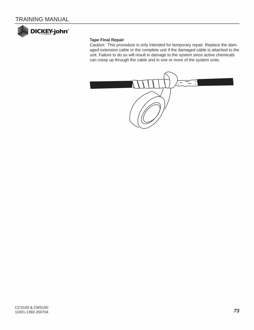
CCS100 & CMS100 11001-1392-200704
TRAINING MANUAL
73
Tape Final RepairCaution: This procedure is only intended for temporary repair. Replace the dam-aged extension cable or the complete unit if the damaged cable is attached to the unit. Failure to do so will result in damage to the system since active chemicals can creep up through the cable and in one or more of the system units.

TRAINING MANUAL
CCS100 & CMS100 11001-1392-20070474
Troubleshooting Sensors
System Sensors and other Device Failures
During normal system operation, the alarm and console display indicates the status of the system sensors and product application devices. If a failure occurs, the operator is alerted by the alarm and the console display so that the problem can be quickly investigated. If the CMS 100 unit is also installed, it is very use-ful in isolating a failed sensor. Also the valve actuator or some of the mechanical devices may also fail.
Switch ModuleThis device contains only a switch and a Sonalert. The switch can be veri-fi ed quickly with an ohmmeter. The condition of the Sonalert can be de-termined by applying +12 volts across the terminals. Be sure to apply the positive voltage lead to the positive terminal (RED wire).
Ground Speed SensorOne of three types of ground speed sensors is used; (1) radar sensor, (2) in-line speedometer drive sensor or (3) magnetic distance sensor. Begin by visually inspecting the cable and sensor for damage. Check all connections and inspect the sensor mounting. If a radar sensor is used, check for exces-sive vibration. Start the vehicle engine and slowly increase engine RPM to the governed rate or operating RPM while observing the display on the CMS 100. The display should remain at zero. If not, the radar mounting is not secure.
If no ground speed is displayed during operation, a simple test can be con-ducted to prove the harness by using a small jumper wire. Place the jumper between the ground conductor and the signal input of the cable. Be sure to identify the correct pins. The main system fuse will blow if the +12 volt line is shorted to ground. Identify the correct pins and intermittently make and break the connection as rapidly as possible. The results are a series of ran-dom pulses which should generate some speed indication on the CMS 100 display. If the display responds, the cabling and console are normal mean-ing the ground speed sensor is the cause.
If a magnetic distance sensor is installed, a simple ohmmeter can be used to prove its operation. Connect the ohmmeter directly across the sensor element. The reading should be infi nity when the magnet is away from the sensor and zero ohms when the magnet is next to the sensor. Also, a click should be heard when the magnet is passed near the sensor.
Status SwitchThe microswitch can be checked with an ohmmeter.
Application Rate SensorThe application rate sensor is mounted on the drive shaft of the conveyor to monitor the rotational rate of the shaft. A simple functional test, similar to the ground speed sensor, can be performed to prove the harness by using a small jumper (wire) to intermittently make and break a connection between ground and the signal line. Be sure to identify the correct pins. If the +12 volt
1.
2.
3.
4.
EXHIBIT 8

CCS100 & CMS100 11001-1392-200704
TRAINING MANUAL
75
line is shorted to ground, the main system fuse will blow.
Hydraulic Control Valve (Granular)The hydraulic control valve regulates the conveyor speed electrically via the CCS100 console. If any of the spreader components, such as the hydraulic pump or hydraulic motors are not operating properly, the control system may appear to be faulty. Check that all the mechanical devices are operating nor-mally before suspecting any of the control system components. Check that the valve operates in the manual mode. If not, disconnect the cable to the actuator driver circuits and measure for drive signals. If no signals are pres-ent on the three lines, suspect the cables and then the console (CCS 100). If signals are observed on the lines, try a new valve driver actuator model. If the control system functions normally in the FLUSH mode but does not open in the AUTO mode, the problem may be a faulty ground speed input.L
Liquid Control ValveThe liquid control valve controls the amount of liquid available for fi eld ap-plication. If the control system is not functioning correctly, fi rst check that all other system mechanical devices are functioning as expected. Then check to make sure the ground speed sensor is functioning. Also, be sure to check the pressure transducer on a sprayer system and the fl ow meter on the anhydrous system.
Be sure the valve is operating in the manual mode. Solicit the aid of an extra person. Hold the switch module switch in the FLUSH position. The control valve should be heard opening for approximately 1.5 seconds. Release the FLUSH switch and again the control valve should be heard closing for approximately 1.5 seconds. If the motor in the valve is not running, then the control valve actuator or the cabling is defective.
FlowmeterThe fl owmeter sensor senses the rotation of the paddle wheel as the fl ow of anhydrous ammonia passes. If the fl owmeter ceases to produce pulses, be-gin by checking the wiring to the fl owmeter. Remove the fl owmeter module and reach inside the venture tube with a small pencil or wire and spin the paddle wheel. If the paddle wheel does not freely spin, repair the cause. If the paddle wheel is found free, replace the fl owmeter module.
Fan RPM SensorThe fan sensor is easily checked by waving a piece of metal quickly back and forth across the sensor’s end while observing the CMS 100 display. Some reading should be observed. Assuming the cabling has been checked and no reading is generated, try a new sensor.
Hopper Level SensorA sensor failure is fi rst detected at the console by an improper readout. If this occurs try unplugging the sensor and see whether the condition chang-es. If it does not, check the cabling. If it does, replace the sensor. If the mes-sage on the display is simply indicating low too soon or not soon enough, inspect the mounting position of the sensor.
5.
6.
7.
8.
9.

TRAINING MANUAL
CCS100 & CMS100 11001-1392-20070476
Pressure TransducerBefore checking a pressure sensor, release all the pressure from the lines or completely remove the sensor from the boom and then perform a Zero Pressure Calibration. If the constant comes up .0000, check for a +12 volts at the sensor connection on the harness and also check continuity on the green wire from the sensor connection to console connection (see Wir-ing Diagram). If +12 volts is not present, check continuity of the power and ground wires. If all harness checks are normal or if the Zero Pressure Cali-bration constant reads 1.000 or more, replace the sensor.
10.

CCS100 & CMS100 11001-1392-200704
TRAINING MANUAL
77
Headquarters:5200 Dickey-john Road, Auburn, IL 62615TEL: 217-438-3371, FAX: 217-438-6012, WEB: www.dickey-john.com
Europe:DICKEY-john Europe S.A., 165, boulevard de Valmy, 92706 – Columbes – FranceTEL: 33 (0) 1 41 19 21 80, FAX: 33 (0) 1 47 86 00 07
For DICKEY- john Service Department, call 1-800-637-3302 in either the U.S.A. or Canada
Dealers have the responsibility of calling to the attention of their customers the following warranty prior to acceptance of an order from their customer for any DICKEY-john product.
DICKEY-john® WARRANTY DICKEY-john warrants to the original purchaser for use that, if any part of the prod-uct proves to be defective in material or workmanship within one year from date of original installation, and is returned to DICKEY-john within 30 days after such defect is discovered, DICKEY-john will (at our option) either replace or repair said part. This warranty does not apply to damage resulting from misuse, neglect, accident, or improper installation or main-tenance. Said part will not be considered defective if it substantially fulfi lls the performance expectations. THE FOREGOING WARRANTY IS EXCLUSIVE AND IN LIEU OF ALL OTHER WARRANTIES OF MERCHANTABILITY, FITNESS FOR PURPOSE, AND OF ANY OTHER TYPE, WHETHER EXPRESS OR IMPLIED. DICKEY-john neither assumes nor authorizes anyone to assume for it any other obligation or liability in connection with said part and will not be liable for consequential damages. Purchaser accepts these terms and warranty limi-tations unless the product is returned within fi fteen days for full refund of purchase price.