Embed Size (px)
Citation preview
1
Progress in atomic fountains at LNE-SYRTEJ. Guena, M. Abgrall, D. Rovera, P. Laurent, B. Chupin, M. Lours, G. Santarelli, P. Rosenbusch, M.E. Tobar,
R. Li, K. Gibble, A. Clairon, and S. Bize
Abstract—We give an overview of the work done with theLNE-SYRTE fountain ensemble during the last five years. Aftera description of the clock ensemble, comprising three fountainsFO1, FO2 and FOM, and its newest developments, we reviewrecent studies of several systematic frequency shifts. This includesthe distributed cavity phase shift which we evaluate for theFO1 and FOM fountains, applying the techniques of our recentwork on FO2. We also report calculations of the microwavelensing frequency shift for the three fountains, review thestatus of the blackbody radiation shift, and summarize recentexperimental work to control microwave leakage and spuriousphase perturbations. We give current accuracy budgets. We alsodescribe several applications in time and frequency metrology:fountain comparisons, calibrations of the international atomictime, secondary representation of the SI second based on the87Rb hyperfine frequency, absolute measurements of opticalfrequencies, tests of the T2L2 satellite laser link, and reviewfundamental physics applications of the LNE-SYRTE fountainensemble. Finally, we give a summary of the tests of the PHARAOcold atom space clock performed using the FOM transportablefountain.
I. INTRODUCTION
Atomic fountain clocks provide the most accurate realiza-tion of the SI second and define the accuracy of the widelyused international atomic time (TAI). Ten years ago, a fewformal TAI calibration reports were available each year. Now,there are normally several formal reports each month as aresult of a great deal of effort in several metrology institutesto improve the reliability and long term operation. At LNE-SYRTE, the fountain ensemble typically provides more than20 TAI calibrations each year, about half of all reports. Theselarge improvements in reliability and corresponding capabilityto perform lengthy measurements yield an enhanced ability toinvestigate smaller and smaller frequency shifts, to comparefountain clocks with more stringent uncertainties and to testtheir long term behavior. In turn, applications using atomic
Manuscript received September 15, 2011; accepted January 23, 2012.This work was supported by SYstemes de Reference Temps-Espace
(SYRTE), the Laboratoire National de Metrologie et dEssais (LNE), theCentre National de la Recherche Scientifique (CNRS), Universite Pierre etMarie curie (UPMC), the Observatoire de Paris, the Institut Francilien deRecherche sur les Atomes Froids (IFRAF), the National Science Foundation(NSF), Penn state, the Ville de Paris, the European Space Agency (ESA), andthe Centre National dEtudes Spatiales (CNES).
J. Guena, M. Abgrall, D. Rovera, P. Laurent, B. Chupin, M. Lours, G.Santarelli, P. Rosenbusch, A. Clairon and S. Bize are affiliated to: LNE-SYRTE, Observatoire de Paris, CNRS, UPMC, 61 avenue de l’Observatoire,75014 Paris, France
M. E. Tobar is affiliated to: The School of Physics, University of WesternAustralia, Crawley, Western Australia
R. Li and K. Gibble are affiliated to: The Department of Physics, ThePennsylvania State University, University Park, Pennsylvania 16802, USA
This work was supported by SYRTE, LNE, CNRS, UPMC, Observatoirede Paris, IFRAF, NSF, Penn State, Ville de Paris, ESA and CNES
DOI: http://dx.doi.org/10.1109/TUFFC.2012.2208
fountain clocks have also developed and benefited from theimprovements of the last few years.
In this article, we give an overview of developments andof applications of the LNE-SYRTE atomic fountain ensembleduring the last five years.
II. LNE-SYRTE FOUNTAIN ENSEMBLE
A. Overview
LNE-SYRTE has operated three atomic fountains for morethan a decade. The first, FO1, is a 133Cs fountain which hasbeen in operation since 1994 [1]. The second, FOM, wasoriginally a prototype for the PHARAO1 cold atom spaceclock [2] and was later modified to be a transportable fountainclock. The third, FO2, is a dual fountain which operates with87Rb and 133Cs simultaneously [3]. Development for morethan a decade has continuously improved each of these. Ourdescription here reflects the present configuration.
The three fountains share several features. All of them aregathering atoms in a Lin ⊥ Lin optical molasses with laserbeams oriented to launch atoms vertically in the so-called(1,1,1) configuration2 [4]. The 6 laser beams for the opticalmolasses are obtained from 6 fiber-coupled collimators, whichare designed, machined and tuned to ensure proper alignmentat the few 100 µrad level when placed against the correspond-ing reference surfaces of the vacuum chamber. Similar fiber-coupled collimators provide the other laser beams for stateselection and detection. In all three fountains, including the87Rb part of FO2, the laser system is on a separate opticalbench and the light is coupled to the vacuum system withoptical fibers. The lasers are home-built extended cavity diodelasers, most of which use a narrow band interference filter forwavelength selection [5]. This design is used in the PHARAOcold atom space clock (see VI). Also, it has recently becomecommercially available. The required power is obtained eitherby injection locking another laser diode or using a taperedsemi-conductor laser amplifier. In all three fountains, atoms arelaunched with the moving molasses technique [6] at a velocityof ∼ 4 m.s−1 and a temperature of ∼ 1 µK. Atoms exit thelaunch sequence in the upper hyperfine state. For normal clockoperation, microwave and laser pulses further select the atomsin the mF = 0 Zeeman sub-state of the lower hyperfine state(|F = 3,mF = 0〉 for 133Cs, |F = 1,mF = 0〉 for 87Rb).
All three fountains also have at least one layer of magneticshield that surrounds the entire vacuum system. Notably, the
1PHARAO stands for “Projet d’Horloge Atomique par Refroidissementd’Atomes en Orbite”
2In this configuration, the 3 pairs of counter-propagating laser beams forthe molasses are aligned along the axes of a 3 dimensional orthonormal basis,where the (111) direction is along the vertical direction, as sketched in Fig. 2
arX
iv:1
204.
3621
v1 [
phys
ics.
atom
-ph]
16
Apr
201
2
2
molasses and the detection region are shielded, which isimportant to operate in the presence of the strong magneticfield fluctuations as of many urban environments, includingthe Observatoire de Paris. The largest, vertical magnetic fieldcomponent in the lower part of the fountain (molasses anddetection) is measured by a flux-gate magnetometer and ac-tively stabilized with a set of horizontal coils distributed overthe height of the fountain. Two or three additional cylindricalshields with end caps surround only the interrogation regionto further attenuate magnetic field fluctuations. Inside theinnermost shield, a solenoid and a set of compensation coilsprovide a static magnetic field in the range of 80 to 200 nT.The field is homogeneous to 10−3 and stable to 2 × 10⁻⁵
from 1 s to several days, as established by spectroscopy of the|F,mF = 1〉 −→ |F + 1,mF = 1〉 field sensitive transition.This corresponds to a stability of ∼ 4 pT.
All three fountains also use the same strategy to controltemperature and thermal gradients in the interrogation region.The innermost layer surrounding the interrogation is made of amaterial with high thermal conductivity (copper or aluminiumalloy) and is well isolated from the environment to ensure goodtemperature uniformity of this layer. The temperature of thisinnermost layer is monitored using platinum resistors and isallowed to drift slowly, following temperature fluctuations inthe room with a typical time constant of 1 day. The measuredtemperature is used to infer the blackbody radiation tempera-ture seen by the atoms. With this scheme, the temperature ofthe innermost layer is uniform to much better than 0.1 K andno large gradients exist between the inner region and the envi-ronment. This essentially removes the need to care about theimpact of the necessary openings (for the atomic trajectories,pumping,...) on the effective blackbody temperature for theatoms. Using heating devices to change or actively stabilizethe temperature of the innermost layer induced a significantdegradation of the temperature uniformity, which was difficultto compensate, even with segmented heaters. Consequently,this approach was abandoned.
The microwave interrogation cavities in all three fountainsare TE011 copper resonators with two independent microwavefeedthroughs. The microwave synthesizers used to feed thecavities are home built. Despite significant differences, thesesynthesizers share the capability to use the ultra-low phasenoise reference signal (see below II-E) from a cryogenic sap-phire oscillator (CSO) without significant degradation at thelevel of one to a few parts in 1015 at 1 s [7]. Consequently, theshort-term instability of all three fountains is typically limitedby the atomic quantum projection noise [8] and technical noisein the atom detection. The best short-term stability to date forthe operation of an atomic fountain with a high atom numberis 1.6×10⁻¹⁴τ−1/2 as reported in [9] and exemplified in Fig.1. The present version of the synthesizers also incorporate aphase-stable microwave switch [10] which helps to assess andremove leakage fields that may affect the interrogation process,independent of other systematic effects. Some details are givenin III-D.
For all three fountains, the computer system allows auto-mated control of most of the important parameters, enablingroutine implementation of multiple interleaved measurements
1 10 100 100010-15
10-14
Detected atom number Nat=5x10⁶
Idem, all Detected atom number N
at/2
Frac
tiona
l fre
quen
cy in
stab
ility
Averaging time (s)
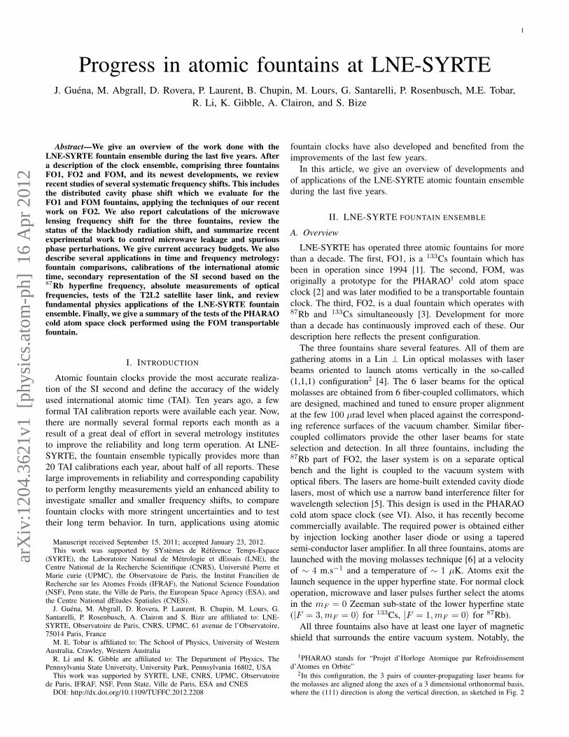
Fig. 1. Fractional frequency instability of FO2-Cs fountain when usinga cryogenic sapphire oscillator as a reference signal. The black points areobtained for a high atom number: Nat = 5 × 10⁶ detected atoms. The redpoints are obtained for Nat/2 detected atoms. The blue line corresponds to1.6 × 10−14τ−1/2. Above 100 s, frequency fluctuations of the ultra-stableinterrogation signal (see II-E), common to the high and low atom numbermeasurements, are apparent.
with different configurations to study systematic shifts. Alarge number of parameters (laser powers, temperatures in theinterrogation region, temperatures in the environment, at theCs or Rb sources, humidity,...) are frequently monitored. Themicrowave power is regularly optimized and the magnetic fieldis verified via spectroscopy of a field sensitive transition, withautomated computer controlled sequences.
B. FO1
FO1 uses a 2 dimensional magneto-optical trap (2DMOT)[11] as a source of slow atoms to load the optical molasses.An advantage of this type of source is that it confines thehigh alkali vapor pressure to the 2DMOT chamber, yieldinga large number of cold atoms in the molasses while keepingsource consumption low. It also facilitates a better vacuum inthe molasses region, thereby minimizing perturbations in thedetection region and the contamination of the interrogation,including the microwave cavity, by background alkali vapor.With higher laser powers in the 2DMOT, it should be possibleto reproduce the atom numbers previously obtained witha chirped-slowed thermal atomic beam, that gave the bestreported fountain stability [9], while consuming an order ofmagnitude less of alkali metal. So far, the laser power devotedto the 2DMOT yields ∼ 4 times fewer atoms in the molassesthan with our best chirped-cooled atomic beam. Note that2DMOT loading of the molasses has some disadvantages.Besides the quite intricated mechanical and optical design andthe need for extra laser sources, we observe a degradationof the 2DMOT laser windows that are in contact with therelatively high alkali vapor pressure (up to 10−4 Pa) after afew years of almost continuous operation. Also, loading themolasses asymmetrically from the slow atom beam from the2DMOT, leads to a non-spherical, complicated atomic clouddistribution which makes the investigation of some systematic
3
frequency shifts more difficult. Note however, that by using theadiabatic passage method to change the atom number [12],the extrapolation of the cold collision shift to zero densityis essentially unaffected by distortions of the atomic cloud’sshape.
The microwave cavity in FO1 has a diameter of 42.99 mmand a length of 42.88 mm. The below-cutoff guides that letthe atoms pass through the cavity have a diameter of 12 mmand a length of 60 mm. At the two ends of the cutoff guides,an additional diaphragm with a diameter of 11 mm blocksatoms that could travel close to the copper walls. Each ofthe 2 opposing microwave feedthroughs includes a resonant,polarization-filtering rectangular waveguide section. In thelatest implementation, the cavity has a loaded quality factorof 14000.
The interrogation region in FO1 is currently equipped withStark plates. These can be used to measure the sensitivity ofthe clock transition to static electric fields to determine theStark coefficient for the blackbody radiation shift correction.Alternatively, FO1 can be equipped with a blackbody radiatorto directly measure the blackbody radiation shift (see III-Cbelow).
C. FO2 dual Rb/Cs fountain
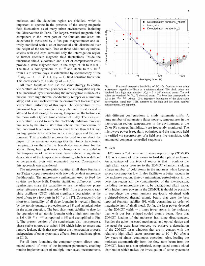
A schematic view of the FO2 dual Rb/Cs fountain is shownin Fig. 2. It uses 2 independent 2DMOT sources for Csand for Rb. For Rb, only the 27.8% abundant isotope isused in the fountain and the use of a 2DMOT eliminatesthe 87Rb background atoms, as for Cs, and also the largerbackground from the unwanted 85Rb isotope. The Rb and Csmolasses are superimposed with dichroic collimators for eachmolasses beam, where the 852 nm light (Cs) and the 780 nmlight (Rb) come from 2 independent optical benches throughpolarizing fibers and are then combined with a dielectricdichroic beamsplitter and collimated with an achromatic lens[13]. Similar dichroic collimators are used for all other laserbeams, the pushing beam for the state selection, detectionbeams and repumper for detection.
As shown in Fig. 2, there are a total of 4 microwave cavitiesfor state selection and interrogation of Rb and Cs atoms.Because both interrogation cavities are in the interrogationregion, their temperature must be uniform and therefore thesame as the environment temperature, which removes anypossibility to independently tune each cavity. Practically, theRb and Cs cavities are a single copper assembly where the Rband Cs cavity resonances were mechanically tuned relative toone another, after a lengthy and tedious process. The resonancefrequencies had to be verified under vacuum and tightlycontrolled thermal conditions, after each tuning step that wasa controlled polishing of the two cavity spacers [14][15]. TheRb and Cs microwave cavities have the same aspect ratio,with the radii scaled by the ratio of the hyperfine frequencies.The cavity for Cs is located at the top. It has a diameter of50.00 mm and a length of 26.87 mm. The Rb cavity has adiameter of 67.25 mm and a length of 36.01 mm. The below-cutoff end cap tubes have a diameter of 12 mm and a length of∼ 50 mm. The 2 opposing microwave feedthroughs for each
cavity include a resonant, polarization filtering rectangularwaveguide section. The loaded quality factor is 7000 for Csand 6000 for Rb.
The Rb and Cs clocks in FO2 routinely operate simulta-neously since 2009 [3]. Two independent but connected andsynchronized computer systems allow the coordination of mul-tiple interleaved measurements with Cs and Rb, as well as allother tasks for each clock, such as monitoring the temperature,the magnetic field, etc. Thus far, the nominal configurationis to launch the Rb and Cs clouds almost simultaneously,but at different velocities, so that the interrogation times aresimultaneous, i.e. the Rb cloud is at the center of the Rb cavitywhen the Cs cloud is at the center of the Cs cavity, on boththe way up and the way down. In this way, the two atomicclouds do not interact with each other during the interrogationprocess, avoiding interspecies collisions. The two clouds alsoremain well separated as they fall to the detection region,allowing the time-resolved detection of Rb and Cs [3]. Asa result, the Rb and Cs clocks run simultaneously withoutimpacting the performance of the other. The flexible computersystems allow for a large number of other possibilities whichwill be explored in the future. For instance, one cloud can bepurposely launched through the other with a well controlledand yet variable speed, in order to study interspecies collisionsat varying energies [16], based either on measurements of thecold collision frequency shift or on direct detection of thescattered wave [17].
D e t e c t i o n z o n e s
S l o w a t o m i c b e a m s
f r o m 2 D - M O T
C o o l i n g &
l a u n c h i n g b e a m s
R b & C s
s e l e c t i o n c a v i t i e s
R b & C s
i n t e r r o g a t i o n
c a v i t i e s
C - f i e l d a n d
m a g n e t i c s h i e l d s
P u s h b e a m
Fig. 2. Schematic view of the FO2 dual Rb/Cs fountain. The 852 nm lightand the 780 nm light for 133Cs and 87Rb atoms are superimposed in eachof the 9 laser beams with dichroic beam splitters. 133Cs and 87Rb atoms arecaptured, launched, state selected, probed and detected simultaneously at eachfountain cycle of 1.6 s. There are 2 independent 2D magneto-optic trap forthe two atomic species.
4
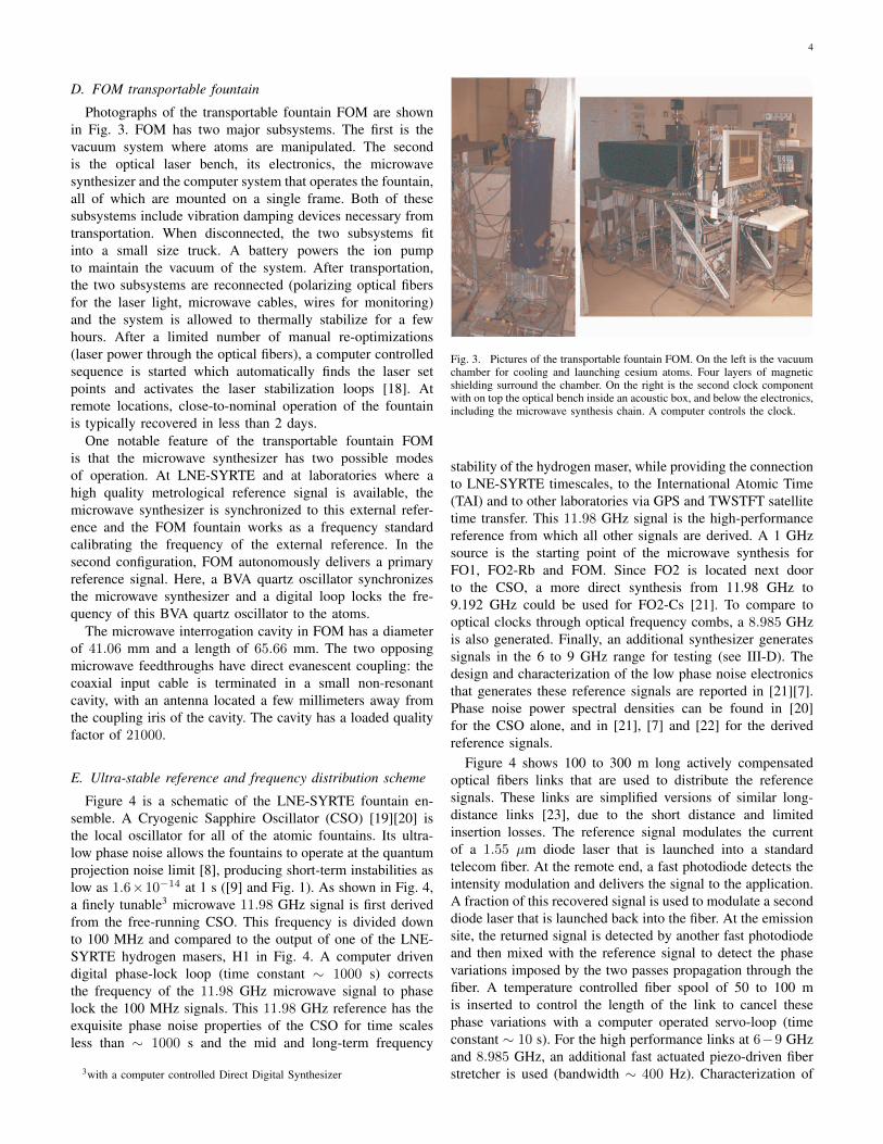
D. FOM transportable fountain
Photographs of the transportable fountain FOM are shownin Fig. 3. FOM has two major subsystems. The first is thevacuum system where atoms are manipulated. The secondis the optical laser bench, its electronics, the microwavesynthesizer and the computer system that operates the fountain,all of which are mounted on a single frame. Both of thesesubsystems include vibration damping devices necessary fromtransportation. When disconnected, the two subsystems fitinto a small size truck. A battery powers the ion pumpto maintain the vacuum of the system. After transportation,the two subsystems are reconnected (polarizing optical fibersfor the laser light, microwave cables, wires for monitoring)and the system is allowed to thermally stabilize for a fewhours. After a limited number of manual re-optimizations(laser power through the optical fibers), a computer controlledsequence is started which automatically finds the laser setpoints and activates the laser stabilization loops [18]. Atremote locations, close-to-nominal operation of the fountainis typically recovered in less than 2 days.
One notable feature of the transportable fountain FOMis that the microwave synthesizer has two possible modesof operation. At LNE-SYRTE and at laboratories where ahigh quality metrological reference signal is available, themicrowave synthesizer is synchronized to this external refer-ence and the FOM fountain works as a frequency standardcalibrating the frequency of the external reference. In thesecond configuration, FOM autonomously delivers a primaryreference signal. Here, a BVA quartz oscillator synchronizesthe microwave synthesizer and a digital loop locks the fre-quency of this BVA quartz oscillator to the atoms.
The microwave interrogation cavity in FOM has a diameterof 41.06 mm and a length of 65.66 mm. The two opposingmicrowave feedthroughs have direct evanescent coupling: thecoaxial input cable is terminated in a small non-resonantcavity, with an antenna located a few millimeters away fromthe coupling iris of the cavity. The cavity has a loaded qualityfactor of 21000.
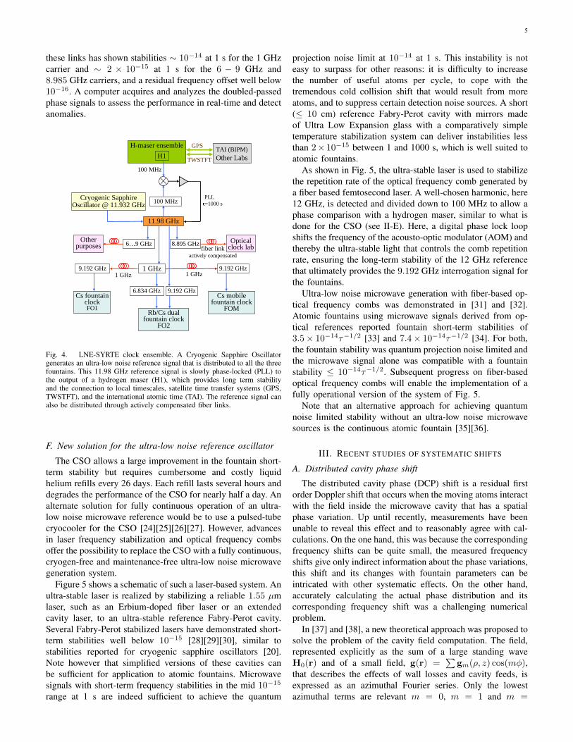
E. Ultra-stable reference and frequency distribution scheme
Figure 4 is a schematic of the LNE-SYRTE fountain en-semble. A Cryogenic Sapphire Oscillator (CSO) [19][20] isthe local oscillator for all of the atomic fountains. Its ultra-low phase noise allows the fountains to operate at the quantumprojection noise limit [8], producing short-term instabilities aslow as 1.6×10⁻¹⁴ at 1 s ([9] and Fig. 1). As shown in Fig. 4,a finely tunable3 microwave 11.98 GHz signal is first derivedfrom the free-running CSO. This frequency is divided downto 100 MHz and compared to the output of one of the LNE-SYRTE hydrogen masers, H1 in Fig. 4. A computer drivendigital phase-lock loop (time constant ∼ 1000 s) correctsthe frequency of the 11.98 GHz microwave signal to phaselock the 100 MHz signals. This 11.98 GHz reference has theexquisite phase noise properties of the CSO for time scalesless than ∼ 1000 s and the mid and long-term frequency
3with a computer controlled Direct Digital Synthesizer
Fig. 3. Pictures of the transportable fountain FOM. On the left is the vacuumchamber for cooling and launching cesium atoms. Four layers of magneticshielding surround the chamber. On the right is the second clock componentwith on top the optical bench inside an acoustic box, and below the electronics,including the microwave synthesis chain. A computer controls the clock.
stability of the hydrogen maser, while providing the connectionto LNE-SYRTE timescales, to the International Atomic Time(TAI) and to other laboratories via GPS and TWSTFT satellitetime transfer. This 11.98 GHz signal is the high-performancereference from which all other signals are derived. A 1 GHzsource is the starting point of the microwave synthesis forFO1, FO2-Rb and FOM. Since FO2 is located next doorto the CSO, a more direct synthesis from 11.98 GHz to9.192 GHz could be used for FO2-Cs [21]. To compare tooptical clocks through optical frequency combs, a 8.985 GHzis also generated. Finally, an additional synthesizer generatessignals in the 6 to 9 GHz range for testing (see III-D). Thedesign and characterization of the low phase noise electronicsthat generates these reference signals are reported in [21][7].Phase noise power spectral densities can be found in [20]for the CSO alone, and in [21], [7] and [22] for the derivedreference signals.
Figure 4 shows 100 to 300 m long actively compensatedoptical fibers links that are used to distribute the referencesignals. These links are simplified versions of similar long-distance links [23], due to the short distance and limitedinsertion losses. The reference signal modulates the currentof a 1.55 µm diode laser that is launched into a standardtelecom fiber. At the remote end, a fast photodiode detects theintensity modulation and delivers the signal to the application.A fraction of this recovered signal is used to modulate a seconddiode laser that is launched back into the fiber. At the emissionsite, the returned signal is detected by another fast photodiodeand then mixed with the reference signal to detect the phasevariations imposed by the two passes propagation through thefiber. A temperature controlled fiber spool of 50 to 100 mis inserted to control the length of the link to cancel thesephase variations with a computer operated servo-loop (timeconstant ∼ 10 s). For the high performance links at 6−9 GHzand 8.985 GHz, an additional fast actuated piezo-driven fiberstretcher is used (bandwidth ∼ 400 Hz). Characterization of
5
these links has shown stabilities ∼ 10−14 at 1 s for the 1 GHzcarrier and ∼ 2 × 10⁻¹⁵ at 1 s for the 6 − 9 GHz and8.985 GHz carriers, and a residual frequency offset well below10−16. A computer acquires and analyzes the doubled-passedphase signals to assess the performance in real-time and detectanomalies.
100 MHz
PLL
H-maser ensemble GPS
TWSTFT
TAI (BIPM)Other LabsH1
100 MHz
11.98 GHz
Other purposes
Optical clock labfiber link
actively compensated
1 GHz
9.192 GHz6.834 GHz
9.192 GHz
Cs fountain clockFO1
Rb/Cs dual fountain clock
FO2
9.192 GHz
Cs mobile fountain clock
FOM
1 GHz 1 GHz
Cryogenic Sapphire Oscillator @ 11.932 GHz =1000 s
6…9 GHz 8.895 GHz
Fig. 4. LNE-SYRTE clock ensemble. A Cryogenic Sapphire Oscillatorgenerates an ultra-low noise reference signal that is distributed to all the threefountains. This 11.98 GHz reference signal is slowly phase-locked (PLL) tothe output of a hydrogen maser (H1), which provides long term stabilityand the connection to local timescales, satellite time transfer systems (GPS,TWSTFT), and the international atomic time (TAI). The reference signal canalso be distributed through actively compensated fiber links.
F. New solution for the ultra-low noise reference oscillator
The CSO allows a large improvement in the fountain short-term stability but requires cumbersome and costly liquidhelium refills every 26 days. Each refill lasts several hours anddegrades the performance of the CSO for nearly half a day. Analternate solution for fully continuous operation of an ultra-low noise microwave reference would be to use a pulsed-tubecryocooler for the CSO [24][25][26][27]. However, advancesin laser frequency stabilization and optical frequency combsoffer the possibility to replace the CSO with a fully continuous,cryogen-free and maintenance-free ultra-low noise microwavegeneration system.
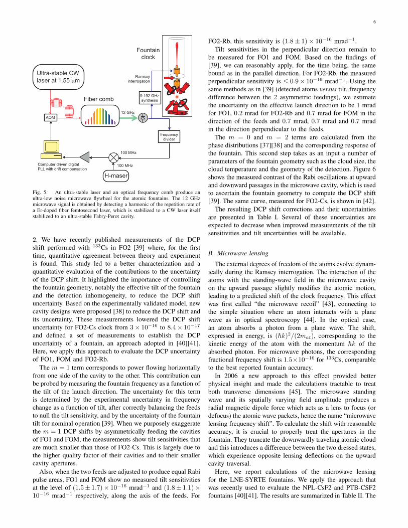
Figure 5 shows a schematic of such a laser-based system. Anultra-stable laser is realized by stabilizing a reliable 1.55 µmlaser, such as an Erbium-doped fiber laser or an extendedcavity laser, to an ultra-stable reference Fabry-Perot cavity.Several Fabry-Perot stabilized lasers have demonstrated short-term stabilities well below 10−15 [28][29][30], similar tostabilities reported for cryogenic sapphire oscillators [20].Note however that simplified versions of these cavities canbe sufficient for application to atomic fountains. Microwavesignals with short-term frequency stabilities in the mid 10−15
range at 1 s are indeed sufficient to achieve the quantum
projection noise limit at 10−14 at 1 s. This instability is noteasy to surpass for other reasons: it is difficulty to increasethe number of useful atoms per cycle, to cope with thetremendous cold collision shift that would result from moreatoms, and to suppress certain detection noise sources. A short(≤ 10 cm) reference Fabry-Perot cavity with mirrors madeof Ultra Low Expansion glass with a comparatively simpletemperature stabilization system can deliver instabilities lessthan 2× 10⁻¹⁵ between 1 and 1000 s, which is well suited toatomic fountains.
As shown in Fig. 5, the ultra-stable laser is used to stabilizethe repetition rate of the optical frequency comb generated bya fiber based femtosecond laser. A well-chosen harmonic, here12 GHz, is detected and divided down to 100 MHz to allow aphase comparison with a hydrogen maser, similar to what isdone for the CSO (see II-E). Here, a digital phase lock loopshifts the frequency of the acousto-optic modulator (AOM) andthereby the ultra-stable light that controls the comb repetitionrate, ensuring the long-term stability of the 12 GHz referencethat ultimately provides the 9.192 GHz interrogation signal forthe fountains.
Ultra-low noise microwave generation with fiber-based op-tical frequency combs was demonstrated in [31] and [32].Atomic fountains using microwave signals derived from op-tical references reported fountain short-term stabilities of3.5× 10−14τ−1/2 [33] and 7.4× 10⁻¹⁴τ−1/2 [34]. For both,the fountain stability was quantum projection noise limited andthe microwave signal alone was compatible with a fountainstability ≤ 10−14τ−1/2. Subsequent progress on fiber-basedoptical frequency combs will enable the implementation of afully operational version of the system of Fig. 5.
Note that an alternative approach for achieving quantumnoise limited stability without an ultra-low noise microwavesources is the continuous atomic fountain [35][36].
III. RECENT STUDIES OF SYSTEMATIC SHIFTS
A. Distributed cavity phase shift
The distributed cavity phase (DCP) shift is a residual firstorder Doppler shift that occurs when the moving atoms interactwith the field inside the microwave cavity that has a spatialphase variation. Up until recently, measurements have beenunable to reveal this effect and to reasonably agree with cal-culations. On the one hand, this was because the correspondingfrequency shifts can be quite small, the measured frequencyshifts give only indirect information about the phase variations,this shift and its changes with fountain parameters can beintricated with other systematic effects. On the other hand,accurately calculating the actual phase distribution and itscorresponding frequency shift was a challenging numericalproblem.
In [37] and [38], a new theoretical approach was proposed tosolve the problem of the cavity field computation. The field,represented explicitly as the sum of a large standing waveH0(r) and of a small field, g(r) =
∑gm(ρ, z) cos(mφ),
that describes the effects of wall losses and cavity feeds, isexpressed as an azimuthal Fourier series. Only the lowestazimuthal terms are relevant m = 0, m = 1 and m =
6
9 . 1 9 2 G H zs y n t h e s i s
f r e q u e n c yd i v i d e r
F i b e r c o m b
F o u n t a i nc l o c k
R a m s e yi n t e r r o g a t i o n
U l t r a - s t a b l e C W
l a s e r a t 1 . 5 5 m m
H - m a s e r
A O M
C o m p u t e r d r i v e n d i g i t a lP L L w i t h d r i f t c o m p e n s a t i o n
1 0 0 M H z
1 0 0 M H z
1 2 G H z
Fig. 5. An ultra-stable laser and an optical frequency comb produce anultra-low noise microwave flywheel for the atomic fountains. The 12 GHzmicrowave signal is obtained by detecting a harmonic of the repetition rate ofa Er-doped fiber femtosecond laser, which is stabilized to a CW laser itselfstabilized to an ultra-stable Fabry-Perot cavity.
2. We have recently published measurements of the DCPshift performed with 133Cs in FO2 [39] where, for the firsttime, quantitative agreement between theory and experimentis found. This study led to a better characterization and aquantitative evaluation of the contributions to the uncertaintyof the DCP shift. It highlighted the importance of controllingthe fountain geometry, notably the effective tilt of the fountainand the detection inhomogeneity, to reduce the DCP shiftuncertainty. Based on the experimentally validated model, newcavity designs were proposed [38] to reduce the DCP shift andits uncertainty. These measurements lowered the DCP shiftuncertainty for FO2-Cs clock from 3× 10⁻¹⁶ to 8.4× 10⁻¹⁷
and defined a set of measurements to establish the DCPuncertainty of a fountain, an approach adopted in [40][41].Here, we apply this approach to evaluate the DCP uncertaintyof FO1, FOM and FO2-Rb.
The m = 1 term corresponds to power flowing horizontallyfrom one side of the cavity to the other. This contribution canbe probed by measuring the fountain frequency as a function ofthe tilt of the launch direction. The uncertainty for this termis determined by the experimental uncertainty in frequencychange as a function of tilt, after correctly balancing the feedsto null the tilt sensitivity, and by the uncertainty of the fountaintilt for nominal operation [39]. When we purposely exaggeratethe m = 1 DCP shifts by asymmetrically feeding the cavitiesof FO1 and FOM, the measurements show tilt sensitivities thatare much smaller than those of FO2-Cs. This is largely due tothe higher quality factor of their cavities and to their smallercavity apertures.
Also, when the two feeds are adjusted to produce equal Rabipulse areas, FO1 and FOM show no measured tilt sensitivitiesat the level of (1.5± 1.7)× 10−16 mrad−1 and (1.8± 1.1)×10−16 mrad−1 respectively, along the axis of the feeds. For
FO2-Rb, this sensitivity is (1.8± 1)× 10−16 mrad−1.Tilt sensitivities in the perpendicular direction remain to
be measured for FO1 and FOM. Based on the findings of[39], we can reasonably apply, for the time being, the samebound as in the parallel direction. For FO2-Rb, the measuredperpendicular sensitivity is ≤ 0.9× 10⁻¹⁶ mrad−1. Using thesame methods as in [39] (detected atoms versus tilt, frequencydifference between the 2 asymmetric feedings), we estimatethe uncertainty on the effective launch direction to be 1 mradfor FO1, 0.2 mrad for FO2-Rb and 0.7 mrad for FOM in thedirection of the feeds and 0.7 mrad, 0.7 mrad and 0.7 mradin the direction perpendicular to the feeds.
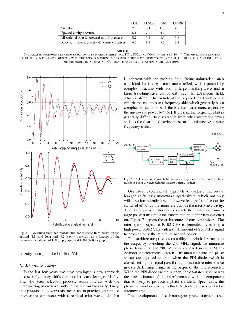
The m = 0 and m = 2 terms are calculated from thephase distributions [37][38] and the corresponding response ofthe fountain. This second step takes as an input a number ofparameters of the fountain geometry such as the cloud size, thecloud temperature and the geometry of the detection. Figure 6shows the measured contrast of the Rabi oscillations at upwardand downward passages in the microwave cavity, which is usedto ascertain the fountain geometry to compute the DCP shift[39]. The same curve, measured for FO2-Cs, is shown in [42].
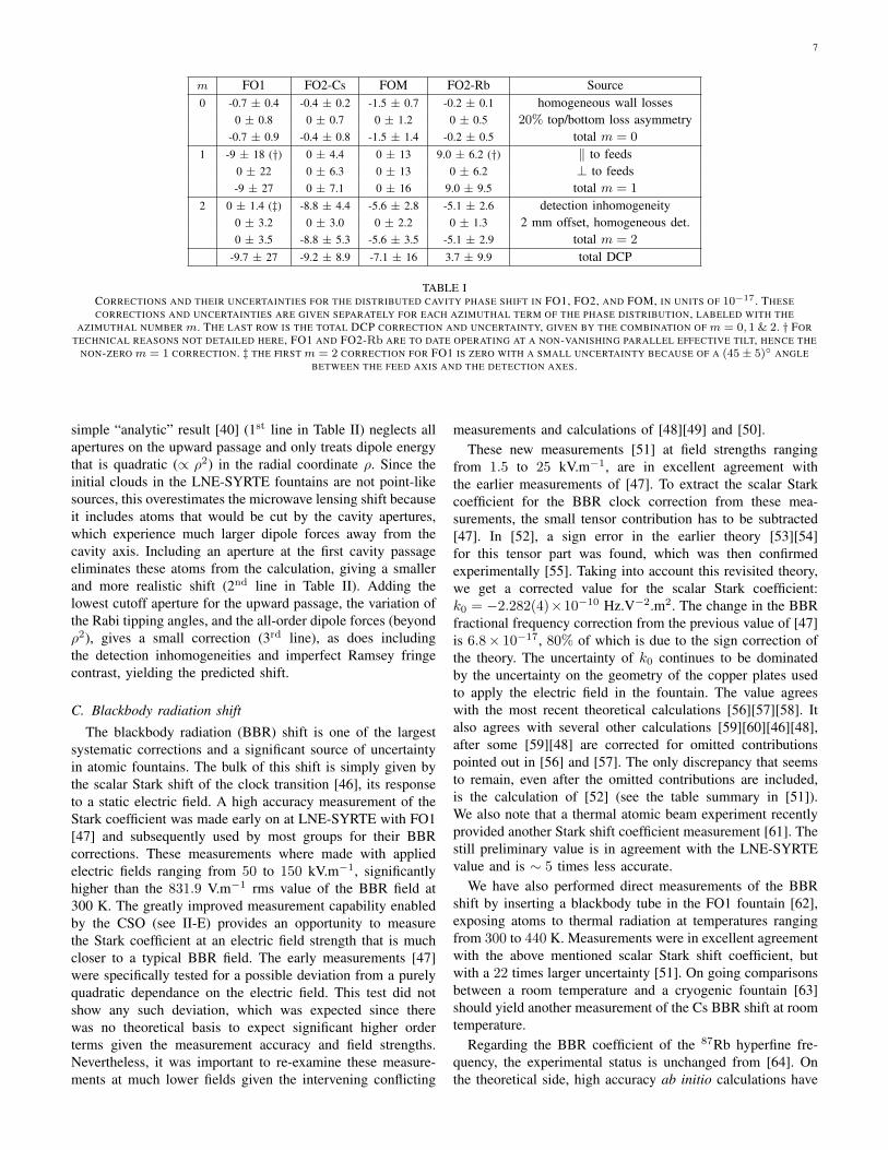
The resulting DCP shift corrections and their uncertaintiesare presented in Table I. Several of these uncertainties areexpected to decrease when improved measurements of the tiltsensitivities and tilt uncertainties will be available.
B. Microwave lensing
The external degrees of freedom of the atoms evolve dynam-ically during the Ramsey interrogation. The interaction of theatoms with the standing-wave field in the microwave cavityon the upward passage slightly modifies the atomic motion,leading to a predicted shift of the clock frequency. This effectwas first called “the microwave recoil” [43], connecting tothe simple situation where an atom interacts with a planewave as in optical spectroscopy [44]. In the optical case,an atom absorbs a photon from a plane wave. The shift,expressed in energy, is (hk)2/(2mat), corresponding to thekinetic energy of the atom with the momentum hk of theabsorbed photon. For microwave photons, the correspondingfractional frequency shift is 1.5×10⁻¹⁶ for 133Cs, comparableto the best reported fountain accuracy.
In 2006 a new approach to this effect provided betterphysical insight and made the calculations tractable to treatboth transverse dimensions [45]. The microwave standingwave and its spatially varying field amplitude produces aradial magnetic dipole force which acts as a lens to focus (ordefocus) the atomic wave packets, hence the name “microwavelensing frequency shift”. To calculate the shift with reasonableaccuracy, it is crucial to properly treat the apertures in thefountain. They truncate the downwardly traveling atomic cloudand this introduces a difference between the two dressed states,which experience opposite lensing deflections on the upwardcavity traversal.
Here, we report calculations of the microwave lensingfor the LNE-SYRTE fountains. We apply the approach thatwas recently used to evaluate the NPL-CsF2 and PTB-CSF2fountains [40][41]. The results are summarized in Table II. The
7
m FO1 FO2-Cs FOM FO2-Rb Source0 -0.7 ± 0.4 -0.4 ± 0.2 -1.5 ± 0.7 -0.2 ± 0.1 homogeneous wall losses
0 ± 0.8 0 ± 0.7 0 ± 1.2 0 ± 0.5 20% top/bottom loss asymmetry-0.7 ± 0.9 -0.4 ± 0.8 -1.5 ± 1.4 -0.2 ± 0.5 total m = 0
1 -9 ± 18 (†) 0 ± 4.4 0 ± 13 9.0 ± 6.2 (†) ‖ to feeds0 ± 22 0 ± 6.3 0 ± 13 0 ± 6.2 ⊥ to feeds-9 ± 27 0 ± 7.1 0 ± 16 9.0 ± 9.5 total m = 1
2 0 ± 1.4 (‡) -8.8 ± 4.4 -5.6 ± 2.8 -5.1 ± 2.6 detection inhomogeneity0 ± 3.2 0 ± 3.0 0 ± 2.2 0 ± 1.3 2 mm offset, homogeneous det.0 ± 3.5 -8.8 ± 5.3 -5.6 ± 3.5 -5.1 ± 2.9 total m = 2
-9.7 ± 27 -9.2 ± 8.9 -7.1 ± 16 3.7 ± 9.9 total DCP
TABLE ICORRECTIONS AND THEIR UNCERTAINTIES FOR THE DISTRIBUTED CAVITY PHASE SHIFT IN FO1, FO2, AND FOM, IN UNITS OF 10−17 . THESECORRECTIONS AND UNCERTAINTIES ARE GIVEN SEPARATELY FOR EACH AZIMUTHAL TERM OF THE PHASE DISTRIBUTION, LABELED WITH THE
AZIMUTHAL NUMBER m. THE LAST ROW IS THE TOTAL DCP CORRECTION AND UNCERTAINTY, GIVEN BY THE COMBINATION OF m = 0, 1 & 2. † FORTECHNICAL REASONS NOT DETAILED HERE, FO1 AND FO2-Rb ARE TO DATE OPERATING AT A NON-VANISHING PARALLEL EFFECTIVE TILT, HENCE THE
NON-ZERO m = 1 CORRECTION. ‡ THE FIRST m = 2 CORRECTION FOR FO1 IS ZERO WITH A SMALL UNCERTAINTY BECAUSE OF A (45± 5)◦ ANGLEBETWEEN THE FEED AXIS AND THE DETECTION AXES.
simple “analytic” result [40] (1st line in Table II) neglects allapertures on the upward passage and only treats dipole energythat is quadratic (∝ ρ2) in the radial coordinate ρ. Since theinitial clouds in the LNE-SYRTE fountains are not point-likesources, this overestimates the microwave lensing shift becauseit includes atoms that would be cut by the cavity apertures,which experience much larger dipole forces away from thecavity axis. Including an aperture at the first cavity passageeliminates these atoms from the calculation, giving a smallerand more realistic shift (2nd line in Table II). Adding thelowest cutoff aperture for the upward passage, the variation ofthe Rabi tipping angles, and the all-order dipole forces (beyondρ2), gives a small correction (3rd line), as does includingthe detection inhomogeneities and imperfect Ramsey fringecontrast, yielding the predicted shift.
C. Blackbody radiation shift
The blackbody radiation (BBR) shift is one of the largestsystematic corrections and a significant source of uncertaintyin atomic fountains. The bulk of this shift is simply given bythe scalar Stark shift of the clock transition [46], its responseto a static electric field. A high accuracy measurement of theStark coefficient was made early on at LNE-SYRTE with FO1[47] and subsequently used by most groups for their BBRcorrections. These measurements where made with appliedelectric fields ranging from 50 to 150 kV.m−1, significantlyhigher than the 831.9 V.m−1 rms value of the BBR field at300 K. The greatly improved measurement capability enabledby the CSO (see II-E) provides an opportunity to measurethe Stark coefficient at an electric field strength that is muchcloser to a typical BBR field. The early measurements [47]were specifically tested for a possible deviation from a purelyquadratic dependance on the electric field. This test did notshow any such deviation, which was expected since therewas no theoretical basis to expect significant higher orderterms given the measurement accuracy and field strengths.Nevertheless, it was important to re-examine these measure-ments at much lower fields given the intervening conflicting
measurements and calculations of [48][49] and [50].These new measurements [51] at field strengths ranging
from 1.5 to 25 kV.m−1, are in excellent agreement withthe earlier measurements of [47]. To extract the scalar Starkcoefficient for the BBR clock correction from these mea-surements, the small tensor contribution has to be subtracted[47]. In [52], a sign error in the earlier theory [53][54]for this tensor part was found, which was then confirmedexperimentally [55]. Taking into account this revisited theory,we get a corrected value for the scalar Stark coefficient:k0 = −2.282(4)×10−10 Hz.V−2.m2. The change in the BBRfractional frequency correction from the previous value of [47]is 6.8× 10⁻¹⁷, 80% of which is due to the sign correction ofthe theory. The uncertainty of k0 continues to be dominatedby the uncertainty on the geometry of the copper plates usedto apply the electric field in the fountain. The value agreeswith the most recent theoretical calculations [56][57][58]. Italso agrees with several other calculations [59][60][46][48],after some [59][48] are corrected for omitted contributionspointed out in [56] and [57]. The only discrepancy that seemsto remain, even after the omitted contributions are included,is the calculation of [52] (see the table summary in [51]).We also note that a thermal atomic beam experiment recentlyprovided another Stark shift coefficient measurement [61]. Thestill preliminary value is in agreement with the LNE-SYRTEvalue and is ∼ 5 times less accurate.
We have also performed direct measurements of the BBRshift by inserting a blackbody tube in the FO1 fountain [62],exposing atoms to thermal radiation at temperatures rangingfrom 300 to 440 K. Measurements were in excellent agreementwith the above mentioned scalar Stark shift coefficient, butwith a 22 times larger uncertainty [51]. On going comparisonsbetween a room temperature and a cryogenic fountain [63]should yield another measurement of the Cs BBR shift at roomtemperature.
Regarding the BBR coefficient of the 87Rb hyperfine fre-quency, the experimental status is unchanged from [64]. Onthe theoretical side, high accuracy ab initio calculations have
8
FO1 FO2-Cs FOM FO2-RbAnalytic 7.8 8.4 11.9 7.0
Upward cavity aperture 6.1 7.0 9.2 5.8
All order dipole & upward cutoff aperture 5.7 6.5 8.6 5.6
Detection inhomogeneity & Ramsey contrast 6.5 7.3 9.0 6.8
TABLE IICALCULATED MICROWAVE LENSING FRACTIONAL FREQUENCY SHIFTS FOR FO1, FO2, AND FOM, IN UNITS OF 10−17 . THE MICROWAVE LENSING
SHIFT IS GIVEN FOR EACH FOUNTAIN WITH THE APPROXIMATIONS DESCRIBED IN THE TEXT. FROM TOP TO BOTTOM, THE DEGREE OF SOPHISTICATIONOF THE MODEL IS INCREASING. OUR BEST FINAL RESULT IS GIVEN IN THE LAST ROW.
0 2 4 6 8 10 12 14 16 18 20 220.0
0.2
0.4
0.6
0.8
1.0
Tran
sitio
n pr
obab
ility
Rabi flopping angle (in units of )
R1 R2
0 2 4 6 8 100.0
0.2
0.4
0.6
0.8
1.0 R1 R2
Tran
sitio
n pr
obab
ility
Rabi flopping angle (in units of )
Fig. 6. Measured transition probabilities for resonant Rabi pulses on theupward (R1) and downward (R2) cavity traversals, as a function of themicrowave amplitude of FO1 (top graph) and FOM (bottom graph).
recently been published in [65][66].
D. Microwave leakage
In the last few years, we have developed a new approachto assess frequency shifts due to microwave leakage. Ideally,after the state selection process, atoms interact with theinterrogating microwaves only in the microwave cavity duringthe upwards and downwards traversals. In practice, unintendedinteractions can occur with a residual microwave field that
is coherent with the probing field. Being unintended, sucha residual field is by nature uncontrolled, with a potentiallycomplex structure with both a large standing-wave and alarge traveling-wave component. Such an extraneous field,which is difficult to exclude at the required level with purelyelectric means, leads to a frequency shift which generally has acomplicated variation with the fountain parameters, especiallythe microwave power [67][68]. If present, the frequency shift isgenerally difficult to disentangle from other systematic errorssuch as the distributed cavity phase or the microwave lensingfrequency shifts.
d i r e c t i o n a lc o u p l e r
2 0 0 M H z
v a r i a b l ea t t e n u a t i o n
p o w e rc o m b i n e r
p h a s es h i f t e r O U T
9 . 1 9 2 G H z
T T L
P I N d i o d e s w i t c h
8 . 9 9 2 G H z
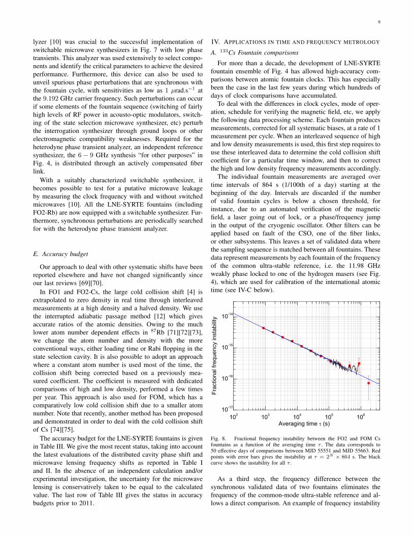
Fig. 7. Schematic of a switchable microwave synthesizer with a low phasetransient using a Mach-Zehnder interferometric switch.
Our latest experimental approach to evaluate microwaveleakage shifts uses microwave synthesizers, which not onlywill have intrinsically low microwave leakage but also can beswitched off when the atoms are outside the microwave cavity.The challenge is to develop a switch that does not cause alarge phase transient of the transmitted field after it is switchedon. Figure 7 depicts the architecture of our synthesizers. Theinterrogation signal at 9.192 GHz is generated by mixing ahigh power 8.992 GHz with a small amount of 200 MHz signalto produce only the minimum needed power.
This architecture provides an ability to switch the carrier atthe output by switching the 200 MHz signal. To minimizephase transients, the 200 MHz is switched using a Mach-Zehnder interferometric switch. The attenuator and the phaseshifter are adjusted so that, when the PIN diode switch isclosed, letting the signal pass through, destructive interferencegives a dark fringe fringe at the output of the interferometer.When the PIN diode switch is open, the on-state signal passesthe direct channel of the interferometer with no componentthat is likely to produce a phase transient. Specifically, thephase transient occurring in the PIN diode as it is switched iscircumvented.
The development of a heterodyne phase transient ana-
9
lyzer [10] was crucial to the successful implementation ofswitchable microwave synthesizers in Fig. 7 with low phasetransients. This analyzer was used extensively to select compo-nents and identify the critical parameters to achieve the desiredperformance. Furthermore, this device can also be used tounveil spurious phase perturbations that are synchronous withthe fountain cycle, with sensitivities as low as 1 µrad.s−1 atthe 9.192 GHz carrier frequency. Such perturbations can occurif some elements of the fountain sequence (switching of fairlyhigh levels of RF power in acousto-optic modulators, switch-ing of the state selection microwave synthesizer, etc) perturbthe interrogation synthesizer through ground loops or otherelectromagnetic compatibility weaknesses. Required for theheterodyne phase transient analyzer, an independent referencesynthesizer, the 6 − 9 GHz synthesis “for other purposes” inFig. 4, is distributed through an actively compensated fiberlink.
With a suitably characterized switchable synthesizer, itbecomes possible to test for a putative microwave leakageby measuring the clock frequency with and without switchedmicrowaves [10]. All the LNE-SYRTE fountains (includingFO2-Rb) are now equipped with a switchable synthesizer. Fur-thermore, synchronous perturbations are periodically searchedfor with the heterodyne phase transient analyzer.
E. Accuracy budget
Our approach to deal with other systematic shifts have beenreported elsewhere and have not changed significantly sinceour last reviews [69][70].
In FO1 and FO2-Cs, the large cold collision shift [4] isextrapolated to zero density in real time through interleavedmeasurements at a high density and a halved density. We usethe interrupted adiabatic passage method [12] which givesaccurate ratios of the atomic densities. Owing to the muchlower atom number dependent effects in 87Rb [71][72][73],we change the atom number and density with the moreconventional ways, either loading time or Rabi flopping in thestate selection cavity. It is also possible to adopt an approachwhere a constant atom number is used most of the time, thecollision shift being corrected based on a previously mea-sured coefficient. The coefficient is measured with dedicatedcomparisons of high and low density, performed a few timesper year. This approach is also used for FOM, which has acomparatively low cold collision shift due to a smaller atomnumber. Note that recently, another method has been proposedand demonstrated in order to deal with the cold collision shiftof Cs [74][75].
The accuracy budget for the LNE-SYRTE fountains is givenin Table III. We give the most recent status, taking into accountthe latest evaluations of the distributed cavity phase shift andmicrowave lensing frequency shifts as reported in Table Iand II. In the absence of an independent calculation and/orexperimental investigation, the uncertainty for the microwavelensing is conservatively taken to be equal to the calculatedvalue. The last row of Table III gives the status in accuracybudgets prior to 2011.
IV. APPLICATIONS IN TIME AND FREQUENCY METROLOGY
A. 133Cs Fountain comparisons
For more than a decade, the development of LNE-SYRTEfountain ensemble of Fig. 4 has allowed high-accuracy com-parisons between atomic fountain clocks. This has especiallybeen the case in the last few years during which hundreds ofdays of clock comparisons have accumulated.
To deal with the differences in clock cycles, mode of oper-ation, schedule for verifying the magnetic field, etc, we applythe following data processing scheme. Each fountain producesmeasurements, corrected for all systematic biases, at a rate of 1measurement per cycle. When an interleaved sequence of highand low density measurements is used, this first step requires touse these interleaved data to determine the cold collision shiftcoefficient for a particular time window, and then to correctthe high and low density frequency measurements accordingly.
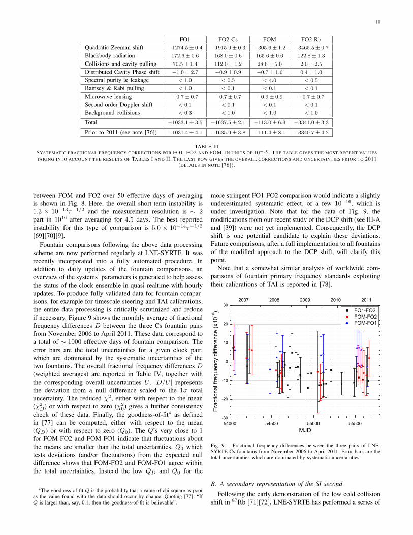
The individual fountain measurements are averaged overtime intervals of 864 s (1/100th of a day) starting at thebeginning of the day. Intervals are discarded if the numberof valid fountain cycles is below a chosen threshold, forinstance, due to an automated verification of the magneticfield, a laser going out of lock, or a phase/frequency jumpin the output of the cryogenic oscillator. Other filters can beapplied based on fault of the CSO, one of the fiber links,or other subsystems. This leaves a set of validated data wherethe sampling sequence is matched between all fountains. Thesedata represent measurements by each fountain of the frequencyof the common ultra-stable reference, i.e. the 11.98 GHzweakly phase locked to one of the hydrogen masers (see Fig.4), which are used for calibration of the international atomictime (see IV-C below).
102 103 104 105 10610-17
10-16
10-15
10-14
Frac
tiona
l fre
quen
cy in
stab
ility
Averaging time (s)
Fig. 8. Fractional frequency instability between the FO2 and FOM Csfountains as a function of the averaging time τ . The data corresponds to50 effective days of comparisons between MJD 55551 and MJD 55663. Redpoints with error bars gives the instability at τ = 2N × 864 s. The blackcurve shows the instability for all τ .
As a third step, the frequency difference between thesynchronous validated data of two fountains eliminates thefrequency of the common-mode ultra-stable reference and al-lows a direct comparison. An example of frequency instability
10
FO1 FO2-Cs FOM FO2-RbQuadratic Zeeman shift −1274.5± 0.4 −1915.9± 0.3 −305.6± 1.2 −3465.5± 0.7
Blackbody radiation 172.6± 0.6 168.0± 0.6 165.6± 0.6 122.8± 1.3
Collisions and cavity pulling 70.5± 1.4 112.0± 1.2 28.6± 5.0 2.0± 2.5
Distributed Cavity Phase shift −1.0± 2.7 −0.9± 0.9 −0.7± 1.6 0.4± 1.0
Spectral purity & leakage < 1.0 < 0.5 < 4.0 < 0.5
Ramsey & Rabi pulling < 1.0 < 0.1 < 0.1 < 0.1
Microwave lensing −0.7± 0.7 −0.7± 0.7 −0.9± 0.9 −0.7± 0.7
Second order Doppler shift < 0.1 < 0.1 < 0.1 < 0.1
Background collisions < 0.3 < 1.0 < 1.0 < 1.0
Total −1033.1± 3.5 −1637.5± 2.1 −113.0± 6.9 −3341.0± 3.3
Prior to 2011 (see note [76]) −1031.4± 4.1 −1635.9± 3.8 −111.4± 8.1 −3340.7± 4.2
TABLE IIISYSTEMATIC FRACTIONAL FREQUENCY CORRECTIONS FOR FO1, FO2 AND FOM, IN UNITS OF 10−16 . THE TABLE GIVES THE MOST RECENT VALUESTAKING INTO ACCOUNT THE RESULTS OF TABLES I AND II. THE LAST ROW GIVES THE OVERALL CORRECTIONS AND UNCERTAINTIES PRIOR TO 2011
(DETAILS IN NOTE [76]).
between FOM and FO2 over 50 effective days of averagingis shown in Fig. 8. Here, the overall short-term instability is1.3 × 10−13τ−1/2 and the measurement resolution is ∼ 2part in 1016 after averaging for 4.5 days. The best reportedinstability for this type of comparison is 5.0 × 10⁻¹⁴τ−1/2
[69][70][9].Fountain comparisons following the above data processing
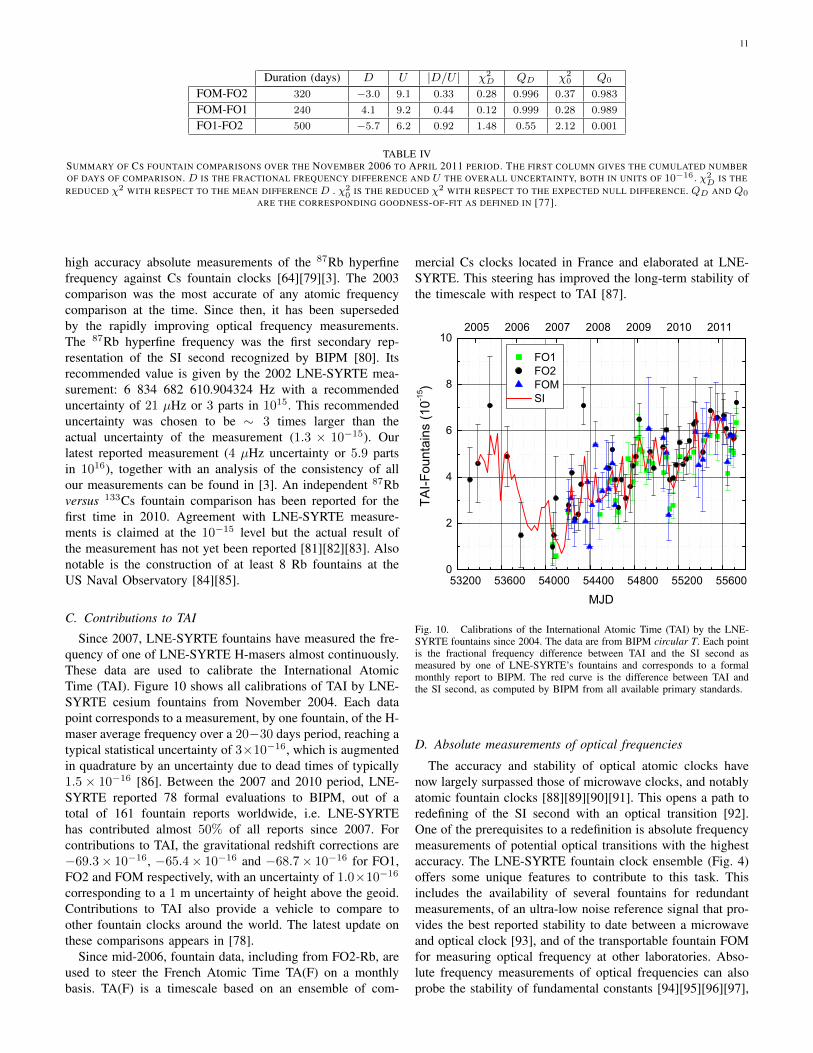
scheme are now performed regularly at LNE-SYRTE. It wasrecently incorporated into a fully automated procedure. Inaddition to daily updates of the fountain comparisons, anoverview of the systems’ parameters is generated to help assessthe status of the clock ensemble in quasi-realtime with hourlyupdates. To produce fully validated data for fountain compar-isons, for example for timescale steering and TAI calibrations,the entire data processing is critically scrutinized and redoneif necessary. Figure 9 shows the monthly average of fractionalfrequency differences D between the three Cs fountain pairsfrom November 2006 to April 2011. These data correspond toa total of ∼ 1000 effective days of fountain comparison. Theerror bars are the total uncertainties for a given clock pair,which are dominated by the systematic uncertainties of thetwo fountains. The overall fractional frequency differences D(weighted averages) are reported in Table IV, together withthe corresponding overall uncertainties U . |D/U | representsthe deviation from a null difference scaled to the 1σ totaluncertainty. The reduced χ2, either with respect to the mean(χ2
D) or with respect to zero (χ20) gives a further consistency
check of these data. Finally, the goodness-of-fit4 as definedin [77] can be computed, either with respect to the mean(QD) or with respect to zero (Q0). The Q’s very close to 1for FOM-FO2 and FOM-FO1 indicate that fluctuations aboutthe means are smaller than the total uncertainties. Q0 whichtests deviations (and/or fluctuations) from the expected nulldifference shows that FOM-FO2 and FOM-FO1 agree withinthe total uncertainties. Instead the low QD and Q0 for the
4The goodness-of-fit Q is the probability that a value of chi-square as pooras the value found with the data should occur by chance. Quoting [77]: “IfQ is larger than, say, 0.1, then the goodness-of-fit is believable”.
more stringent FO1-FO2 comparison would indicate a slightlyunderestimated systematic effect, of a few 10−16, which isunder investigation. Note that for the data of Fig. 9, themodifications from our recent study of the DCP shift (see III-Aand [39]) were not yet implemented. Consequently, the DCPshift is one potential candidate to explain these deviations.Future comparisons, after a full implementation to all fountainsof the modified approach to the DCP shift, will clarify thispoint.
Note that a somewhat similar analysis of worldwide com-parisons of fountain primary frequency standards exploitingtheir calibrations of TAI is reported in [78].
54000 54500 55000 55500-30
-20
-10
0
10
20
302007 2008 2009 2010 2011
FO1-FO2 FOM-FO2 FOM-FO1
MJD
Frac
tiona
l fre
quen
cy d
iffer
ence
(x10
16)
Fig. 9. Fractional frequency differences between the three pairs of LNE-SYRTE Cs fountains from November 2006 to April 2011. Error bars are thetotal uncertainties which are dominated by systematic uncertainties.
B. A secondary representation of the SI second
Following the early demonstration of the low cold collisionshift in 87Rb [71][72], LNE-SYRTE has performed a series of
11
Duration (days) D U |D/U | χ2D QD χ2
0 Q0
FOM-FO2 320 −3.0 9.1 0.33 0.28 0.996 0.37 0.983
FOM-FO1 240 4.1 9.2 0.44 0.12 0.999 0.28 0.989
FO1-FO2 500 −5.7 6.2 0.92 1.48 0.55 2.12 0.001
TABLE IVSUMMARY OF CS FOUNTAIN COMPARISONS OVER THE NOVEMBER 2006 TO APRIL 2011 PERIOD. THE FIRST COLUMN GIVES THE CUMULATED NUMBEROF DAYS OF COMPARISON. D IS THE FRACTIONAL FREQUENCY DIFFERENCE AND U THE OVERALL UNCERTAINTY, BOTH IN UNITS OF 10−16 . χ2
D IS THEREDUCED χ2 WITH RESPECT TO THE MEAN DIFFERENCE D . χ2
0 IS THE REDUCED χ2 WITH RESPECT TO THE EXPECTED NULL DIFFERENCE. QD AND Q0
ARE THE CORRESPONDING GOODNESS-OF-FIT AS DEFINED IN [77].
high accuracy absolute measurements of the 87Rb hyperfinefrequency against Cs fountain clocks [64][79][3]. The 2003comparison was the most accurate of any atomic frequencycomparison at the time. Since then, it has been supersededby the rapidly improving optical frequency measurements.The 87Rb hyperfine frequency was the first secondary rep-resentation of the SI second recognized by BIPM [80]. Itsrecommended value is given by the 2002 LNE-SYRTE mea-surement: 6 834 682 610.904324 Hz with a recommendeduncertainty of 21 µHz or 3 parts in 1015. This recommendeduncertainty was chosen to be ∼ 3 times larger than theactual uncertainty of the measurement (1.3 × 10⁻¹⁵). Ourlatest reported measurement (4 µHz uncertainty or 5.9 partsin 1016), together with an analysis of the consistency of allour measurements can be found in [3]. An independent 87Rbversus 133Cs fountain comparison has been reported for thefirst time in 2010. Agreement with LNE-SYRTE measure-ments is claimed at the 10−15 level but the actual result ofthe measurement has not yet been reported [81][82][83]. Alsonotable is the construction of at least 8 Rb fountains at theUS Naval Observatory [84][85].
C. Contributions to TAI
Since 2007, LNE-SYRTE fountains have measured the fre-quency of one of LNE-SYRTE H-masers almost continuously.These data are used to calibrate the International AtomicTime (TAI). Figure 10 shows all calibrations of TAI by LNE-SYRTE cesium fountains from November 2004. Each datapoint corresponds to a measurement, by one fountain, of the H-maser average frequency over a 20−30 days period, reaching atypical statistical uncertainty of 3×10⁻¹⁶, which is augmentedin quadrature by an uncertainty due to dead times of typically1.5 × 10−16 [86]. Between the 2007 and 2010 period, LNE-SYRTE reported 78 formal evaluations to BIPM, out of atotal of 161 fountain reports worldwide, i.e. LNE-SYRTEhas contributed almost 50% of all reports since 2007. Forcontributions to TAI, the gravitational redshift corrections are−69.3× 10⁻¹⁶, −65.4× 10⁻¹⁶ and −68.7× 10⁻¹⁶ for FO1,FO2 and FOM respectively, with an uncertainty of 1.0×10⁻¹⁶
corresponding to a 1 m uncertainty of height above the geoid.Contributions to TAI also provide a vehicle to compare toother fountain clocks around the world. The latest update onthese comparisons appears in [78].
Since mid-2006, fountain data, including from FO2-Rb, areused to steer the French Atomic Time TA(F) on a monthlybasis. TA(F) is a timescale based on an ensemble of com-
mercial Cs clocks located in France and elaborated at LNE-SYRTE. This steering has improved the long-term stability ofthe timescale with respect to TAI [87].
53200 53600 54000 54400 54800 55200 556000
2
4
6
8
102005 2006 2007 2008 2009 2010 2011
FO1 FO2 FOM SI
TAI-F
ount
ains
(10-1
5 )
MJD
Fig. 10. Calibrations of the International Atomic Time (TAI) by the LNE-SYRTE fountains since 2004. The data are from BIPM circular T. Each pointis the fractional frequency difference between TAI and the SI second asmeasured by one of LNE-SYRTE’s fountains and corresponds to a formalmonthly report to BIPM. The red curve is the difference between TAI andthe SI second, as computed by BIPM from all available primary standards.
D. Absolute measurements of optical frequencies
The accuracy and stability of optical atomic clocks havenow largely surpassed those of microwave clocks, and notablyatomic fountain clocks [88][89][90][91]. This opens a path toredefining of the SI second with an optical transition [92].One of the prerequisites to a redefinition is absolute frequencymeasurements of potential optical transitions with the highestaccuracy. The LNE-SYRTE fountain clock ensemble (Fig. 4)offers some unique features to contribute to this task. Thisincludes the availability of several fountains for redundantmeasurements, of an ultra-low noise reference signal that pro-vides the best reported stability to date between a microwaveand optical clock [93], and of the transportable fountain FOMfor measuring optical frequency at other laboratories. Abso-lute frequency measurements of optical frequencies can alsoprobe the stability of fundamental constants [94][95][96][97],
12
determine the Rydberg constant [98] and test Quantum Elec-trodynamics (QED) [99].
Next, we give an overview of absolute optical frequencymeasurements made with LNE-SYRTE fountain ensemble.
1) Hydrogen 1S− 2S transition measured with FOM atMPQ Garching, Germany: At the Max Planck Institut furQuantenoptik (MPQ) in Garching (Germany), we have mea-sured the absolute frequency of the 1S-2S optical transitionvia 2 photon excitation at 246 nm [100][95][101]. Three mea-surement campaigns were completed in 1999, 2003 and 2010.For these experiments a femto-comb laser is used to measurethe frequency of the excitation laser. The repetition rate islocked to a hydrogen maser whose frequency is simultaneouslymeasured directly by FOM. The noise of the maser signal isfiltered by phase-locking a BVA quartz oscillator to improvethe measurement stability. The last measurement in 2010 hadthe best fractional uncertainty: 4.2 × 10⁻¹⁵ [101]. The mea-sured 1S-2S transition frequency is 2 466 061 413 187 035(10)Hz.
High resolution spectroscopy of hydrogen is interesting totest highly accurate atomic structure calculations for QEDtests [102]. Also, the recent capture of antihydrogen at CERN[103] is a first step toward cooling of antimatter to enablehigh resolution spectroscopy of antihydrogen for fundamentaltests of charge, parity, time reversal (CPT) symmetry and thegravity of antimatter.
2) 40Ca+ optical clock measured with FOM at the Uni-versity of Innsbruck, Austria: In 2007 at the Institut furExperimentalphysik and Quantenoptik, University of Inns-bruck (Austria), we measured the absolute frequency of the4s 2S1/2 − 3d 2D5/2 optical quadrupole transition of atrapped single 40Ca+ ion. The frequency of this transition is411 042 129 776 393.2 (1.0) Hz [104]. This corresponds to afractional frequency uncertainty of 2.4 parts in 1015. Duringthis experiment, FOM was used in the autonomous config-uration mentioned in II-D, where a BVA quartz oscillator isfrequency locked to the FOM spectroscopic signal. The outputof the BVA quartz oscillator synchronizes the repetition rate ofthe femto-comb laser that measures the probe laser frequencyfor the 40Ca+ transition. This quadrupole transition in 40Ca+
ion is another candidate for an optical clock and for tests ofthe stability of fundamental constants.
3) 87Sr and 88Sr optical lattice clocks measured atSYRTE: LNE-SYRTE is developing two Sr optical lat-tice clocks. During their development, several absolute fre-quency measurements of the Sr clock frequency were made[93][105][106][107]. The best reported uncertainty for thesemeasurements is 2.6 × 10⁻¹⁵ [93]. Both Titanium:Sapphirebased and Er-doped fiber based optical frequency combswere used to measure the frequency of the 698 nm laserlight stabilized to the Sr atoms. The 2006 measurements ofthe 87Sr used a fiber optical frequency comb transportedfrom the Physikalisch Technische Bundesanstalt (PTB) inBraunschweig (Germany) [106][93]. As already mentioned,the ultra-stable reference based on a CSO (Fig. 4) allowsthe best reported short-term stability to date for comparingan optical clock to a microwave clock: 6 × 10⁻¹⁴τ−1/2.In the recent measurements, the optical frequency comb is
stabilized to an ultra-stable laser as described in [22], makingthe repetition rate of the femtosecond laser an ultra-stablemicrowave signal. This signal is then measured against theCSO based ultra-stable reference which is in turn measuredby the fountain clocks. Simultaneously, the beat between theoptical frequency comb and the 698 nm light is counted toextract its absolute frequency. Combining these with similarmeasurements by other institutes, stringently tests the stabilityof fundamental constants [94].
4) Measurement of 199Hg and 201Hg optical clock tran-sition frequencies at SYRTE: LNE-SYRTE is developingan optical lattice clock based on neutral mercury. The firstabsolute frequency measurements of the 199Hg and 201Hgoptical clock transition were in 2008 [108]. These initial mea-surements improved the previous knowledge of the transitionfrequency by more than 4 orders of magnitude, to a fractionalfrequency uncertainty of 5× 10⁻¹². More recently, measure-ments against LNE-SYRTE ultra-stable reference were usedto perform the first experimental determination of the magicwavelength for Hg [109]. Ongoing development of the Hgclock is expected to soon yield measurements at the 10−15
level and beyond.
E. Other measurements with the transportable fountain FOM
We have performed frequency comparisons with the engi-neering model of the space clock PHARAO (see VI below and[110]) between 2007 to 2009, at the Centre National d’EtudesSpatiales (CNES) in Toulouse, France. We have also verifiedthe frequency performance of the ACES architecture [111].The test included a ground model of the onboard data handlingunit (XPLC), the Frequency Comparison and DistributionPackage (FCDP), the PHARAO engineering model, and aground model of the Space Hydrogen Maser (SHM). The twoclocks are combined to generate a timescale with the short-term stability of SHM and the long-term stability and accuracyof PHARAO.
F. Remote comparisons via T2L2 satellite laser linkIn 2010, time transfer by the T2L2 laser link via the
JASON2 satellite [112] was tested by comparing FOM at theObservatoire de la Cote d’Azur (OCA) in Grasse (France)with the other LNE-SYRTE fountains at the Observatoire deParis. The common time transfer techniques, carrier phaseGPS and TWSTFT, were also used in parallel. Notable in thiscomparison is the large gravitational redshift, −1.384×10⁻¹³,at the OCA altitude of 1268 m. Preliminary results [113] showthat all the time transfer methods are consistent to within 2 nsover 2 months. The frequency difference between the remotefountains is measured with a typical uncertainty of 1×10⁻¹⁵,which determines the gravitational redshift difference to 10−2.It now remains to refine the analysis and to evaluate theultimate performances of the T2L2 time transfer link. Note thatat MPQ, at CNES and at OCA, FOM also provided calibrationof the TAI by using a GPS receiver and a carrier phase GPSanalysis software developed by CNES or by NRCAN. This isthe first time that a primary frequency standard contributes tosteering the TAI from different sites with different gravitationalredshift [114].

13
V. APPLICATIONS IN FUNDAMENTAL PHYSICS
One of the most interesting applications of atomic clocksis to test fundamental physics. In this section, we reviewcontributions of LNE-SYRTE fountain ensemble to such tests.
A. Stability of constants
Repeated high accuracy comparisons between atomic (ormolecular) frequencies can test the stability of fundamentalconstants such as the fine structure constant α or the electronto proton mass ratio me/mp (see, for instance, [115] [116] andreferences therein). Laboratory experiments usefully comple-ment tests over cosmological timescales since the interpreta-tion does not rely on any assumptions about a cosmologicalmodel [117][118].
A first test performed with LNE-SYRTE fountain ensemblecomes from a series of 87Rb versus 133Cs hyperfine frequencycomparisons made during the development of the FO2 dualRb/Cs fountain [79][69][70] and [119]. In this last 2008 report,a putative time variation of the ratio of the two hyperfinefrequencies is constrained to d ln(νRb/νCs)/dt = (−3.2 ±2.3) × 10−16 yr−1. In terms of fundamental constants, thisresult yields d ln(α−0.49[gRb/gCs])/dt = (−3.2 ± 2.3) ×10−16 yr−1 where gRb and gCs are the nuclear g-factorsin 87Rb and 133Cs. Expressing these g-factors in terms offundamental parameters of the Standard Model [120][121]gives: d ln(α−0.49[mq/ΛQCD]−0.025)/dt = (−3.2 ± 2.3) ×10−16 yr−1, where ΛQCD is the mass scale of QuantumChromodynamics (QCD). An improved analysis includingmore recent measurements, with FO2 in the dual fountainconfiguration, will improve this value significantly.
A second test comes from a series of absolute fre-quency measurements of the 87Sr optical lattice clockby LNE-SYRTE (see IV-D3), the University of Tokyo,Japan and JILA, Boulder, Colorado, USA [94]. To-gether, these constrain the putative variation of νSr/νCs
to d ln(νSr/νCs)/dt = (−7 ± 18) × 10−16 yr−1 corre-sponding to d ln(α2.77[mq/ΛQCD]−0.039[me/ΛQCD])/dt =(7 ± 18) × 10−16 yr−1. The same measurements con-strain the putative variation of this same combina-tion of constants with the gravitational potential toc2d ln(α2.77[mq/ΛQCD]−0.039[me/ΛQCD])/dU = (−5.8 ±8.9) × 10−6, where c is the speed of light and U the grav-itational potential 5. This test relies on exploiting the yearlymodulation of the gravitational potential of the Sun due theeccentricity of the Earth orbit.
Measurements of the H(1S-2S) transition performed at MPQGarching (see IV-D1) using the transportable fountain FOMas a reference, offer a third test: d ln(νH(1S−2S)/νCs)/dt =(−3.2 ± 6.3) × 10−15 yr−1 [95]. This translates tod ln(α2.83[mq/ΛQCD]−0.039[me/ΛQCD])/dt = (3.2 ± 6.3) ×10−15 yr−1, a constraint which will soon improve as a resultof a recent measurement campaign [101].
A fourth test comes from a series of comparisons be-tween the 133Cs and the hydrogen hyperfine frequencies.
5For instance, the gravitational potential created by a point mass m ata distance r is: U(r) = Gm/r where G is the Newtonian constant ofgravitation.
LNE-SYRTE fountain’s contributions to this test were thecalibrations of TAI reported in BIPM Circular T (see IV-C)enabling the connection with 4 hydrogen masers participatingto the elaboration of the NIST AT1 atomic timescale (seefor instance [122]). Other Cs fountain contributions to theexperiment came from PTB in Germany and from the IstitutoNazionale di Ricerca Metrologica (INRIM) in Italy. The anal-ysis was performed at the National Institute of Standards andTechnology (NIST) Boulder, Colorado, USA [123] and gives|c2d ln(νH/νCs)/dU | = (0.1± 1.4)× 10−6, corresponding to|c2d ln(α0.83[mq/ΛQCD]0.11)/dU | = (0.1± 1.4)× 10−6.
Note that instead of using α, mq/ΛQCD and me/ΛQCD
as independent variables, α, µ = me/mp and mq/mp
can be used. The link between the two approaches isd ln(mp/ΛQCD) ' 0.048× d ln(mq/ΛQCD) [121].
B. Test of Lorentz Invariance in the matter sector
The LNE-SYRTE FO2 fountain has tested the anisotropyof space as in Hughes-Drever experiments (see for instance[124]). For this experiment, the fountain sequence is tailoredto probe opposing Zeeman transitions in 133Cs to test for aputative variation of their frequencies when the orientationof the quantization axis changes (here, due the Earth rotation)with respect to a supposedly preferred frame [125], such as theframe of the Cosmic Microwave Background. The experimentwas interpreted within the framework of the Lorentz violatingStandard Model Extension (SME), where it is sensitive to pro-ton parameters corresponding to a largely unexplored region ofthe SME parameter space. The constraints for 4 parameters,already constrained by other measurements, were improvedby as much as 13 orders of magnitude and 4 parameters wereconstrained for the first time. Operating FO2 in the dual Rb/Csconfiguration [3] opens new possibilities for improving andcomplementing these tests.
C. Other tests
The development of LNE-SYRTE fountain ensemble alsooffered a test of Lorentz Local Invariance in the photonsector, not using the fountains, but simply comparing the CSOto a hydrogen maser (see Fig. 4) for a duration that nowexceeds 10 years. This experiment is to date the most stringentKennedy-Thorndike test by a factor of 500. The latest updateis published in [126]. The experiment can also be interpretedin the SME framework [127].
VI. DEVELOPMENT OF THE PHARAO COLD ATOM SPACECLOCK
Atomic Clocks Ensemble in Space (ACES) is a EuropeanSpace Agency (ESA) fundamental physics mission originallyproposed by Laboratoire Kastler Brossel and SYRTE. It isbased on the operation of highly stable and accurate atomicclocks in the microgravity environment of the InternationalSpace Station (ISS) [111]. The time scale generated by theACES clocks on-board the ISS is delivered to Earth througha high-performance two-way time and frequency transferlink. The clock signal is used to perform space-to-ground as
14
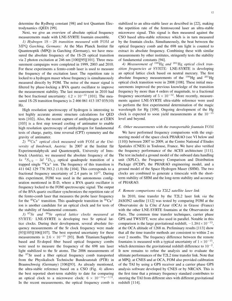
Fig. 11. The engineering model of the PHARAO cold atom space clockunder test at CNES, Toulouse (photo is courtesy of CNES). The picture showsthe vertically mounted “cesium tube”, the vacuum chamber surrounded bythe magnetic shields. The gold-coated box behind the cesium tube containsthe “laser source”. A second gold-coated box, below the laser source, is themicrowave synthesizer. The black box in front, at the bottom of the cesiumtube, is the on-board computer unit.
well as ground-to-ground comparisons of atomic frequencystandards. The ACES scientific objectives cover both funda-mental physics and applications. Tests of Special and Gen-eral Relativity will be performed with improved accuracy,as well as a search for temporal variations of fundamentalconstants. On the application side, frequency comparisonsbetween distant clocks, both space-to-ground and ground-to-ground, will be performed worldwide with unprecedentedresolution. ACES will demonstrate a new type of “relativisticgeodesy”, which, based on a precision measurement of theEinstein’s gravitational red-shift, will resolve differences inthe Earth gravitational potential at the 10 cm level. Finally,ACES will contribute to the improvement of global navigationsatellite systems (GNSS) and to future evolutions of thesesystems. It will demonstrate new methods to monitor theocean surface based on scatterometric measurements of theGNSS signal and it will contribute to the monitoring of theEarth atmosphere through radio-occultation experiments. Theexpected performance is a time stability of 10 ps over tendays (1 ps for common view comparisons between groundclocks) and a frequency accuracy better than 3× 10⁻¹⁶. Theaccuracy and the long term frequency stability are defined bythe PHARAO clock, an instrument developed by the Frenchspace agency CNES and SYRTE. The clock uses cold cesiumatoms, slowly moving through a Ramsey cavity. We have fully
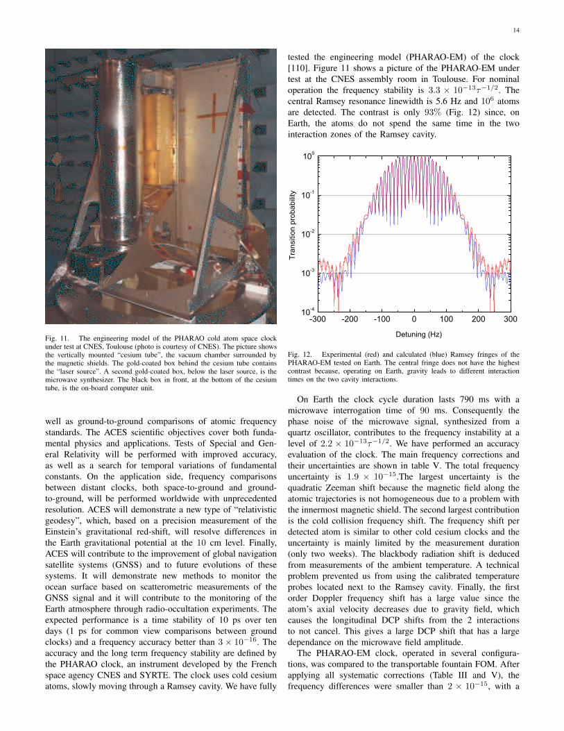
tested the engineering model (PHARAO-EM) of the clock[110]. Figure 11 shows a picture of the PHARAO-EM undertest at the CNES assembly room in Toulouse. For nominaloperation the frequency stability is 3.3 × 10⁻¹³τ−1/2. Thecentral Ramsey resonance linewidth is 5.6 Hz and 106 atomsare detected. The contrast is only 93% (Fig. 12) since, onEarth, the atoms do not spend the same time in the twointeraction zones of the Ramsey cavity.
-300 -200 -100 0 100 200 30010-4
10-3
10-2
10-1
100
Tran
sitio
n pr
obab
ility
Detuning (Hz)
Fig. 12. Experimental (red) and calculated (blue) Ramsey fringes of thePHARAO-EM tested on Earth. The central fringe does not have the highestcontrast because, operating on Earth, gravity leads to different interactiontimes on the two cavity interactions.
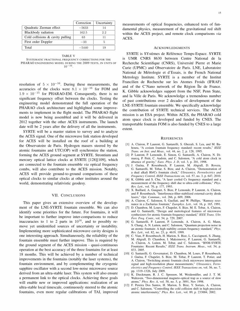
On Earth the clock cycle duration lasts 790 ms with amicrowave interrogation time of 90 ms. Consequently thephase noise of the microwave signal, synthesized from aquartz oscillator, contributes to the frequency instability at alevel of 2.2 × 10⁻¹³τ−1/2. We have performed an accuracyevaluation of the clock. The main frequency corrections andtheir uncertainties are shown in table V. The total frequencyuncertainty is 1.9 × 10⁻¹⁵.The largest uncertainty is thequadratic Zeeman shift because the magnetic field along theatomic trajectories is not homogeneous due to a problem withthe innermost magnetic shield. The second largest contributionis the cold collision frequency shift. The frequency shift perdetected atom is similar to other cold cesium clocks and theuncertainty is mainly limited by the measurement duration(only two weeks). The blackbody radiation shift is deducedfrom measurements of the ambient temperature. A technicalproblem prevented us from using the calibrated temperatureprobes located next to the Ramsey cavity. Finally, the firstorder Doppler frequency shift has a large value since theatom’s axial velocity decreases due to gravity field, whichcauses the longitudinal DCP shifts from the 2 interactionsto not cancel. This gives a large DCP shift that has a largedependance on the microwave field amplitude.
The PHARAO-EM clock, operated in several configura-tions, was compared to the transportable fountain FOM. Afterapplying all systematic corrections (Table III and V), thefrequency differences were smaller than 2 × 10⁻¹⁵, with a
15
Correction UncertaintyQuadratic Zeeman effect −5633 14
Blackbody radiation 162.5 2.2
Cold collisions & cavity pulling 63 11
First order Doppler −33 5
Total −5440 19
TABLE VSYSTEMATIC FRACTIONAL FREQUENCY CORRECTIONS FOR THE
PHARAO ENGINEERING MODEL DURING THE 2009 TESTS, IN UNITS OF10−16 .
resolution of 5 × 10⁻¹⁶. During these measurements, theaccuracies of the clocks were 8.1 × 10⁻¹⁶ for FOM and1.9 × 10−15 for PHARAO-EM. Consequently, there is nosignificant frequency offset between the clocks. Testing theengineering model demonstrated the full operation of thePHARAO clock architecture and highlighted some improve-ments to implement in the flight model. The PHARAO flightmodel is now being assembled and it will be delivered in2012 together with the other ACES instruments. The launchdate will be 2 years after the delivery of all the instruments.
SYRTE will be a master station to survey and to analyzethe ACES signal. One of the microwave link station developedfor ACES will be installed on the roof of a building atthe Observatoire de Paris. Hydrogen masers steered by theatomic fountains and UTC(OP) will synchronize the station,forming the ACES ground segment at SYRTE. Strontium andmercury optical lattice clocks at SYRTE [128][109], whichare connected to the fountain ensemble via optical frequencycombs, will also contribute to the ACES mission. Notably,ACES will provide ground-to-ground comparisons of theseoptical clocks to similar clocks at other institutes around theworld, demonstrating relativistic geodesy.
VII. CONCLUSIONS
This paper gives an extensive overview of the develop-ment of the LNE-SYRTE fountain ensemble. We can alsoidentify some priorities for the future. For fountains, it willbe important to further improve inter-comparisons to reduceinaccuracies to 1 to 2 parts in 1016, and to possibly re-move yet unidentified sources of uncertainty or instability.Implementing more sophisticated microwave cavity designs isone interesting approach. Simultaneously, the reliability of thefountain ensemble must further improve. This is required bythe ground segment of the ACES mission - quasi-continuousoperation at the best accuracy of the three fountains for at least18 months. This will be achieved by a number of technicalimprovements in the fountains (notably the laser systems), thefountain environment, and by complementing the cryogenicsapphire oscillator with a second low-noise microwave sourcederived from an ultra-stable laser. This system will also ensurea permanent link to the optical clocks. Achieving these goalswill enable new or improved applications: realization of anultra-stable local timescale, continuously steered to the atomicfountains, even more regular calibrations of TAI, improved
measurements of optical frequencies, enhanced tests of fun-damental physics, measurement of the gravitational red shiftwithin the ACES project, and remote clock comparisons viaACES.
ACKNOWLEDGMENTS
SYRTE is SYstemes de Reference Temps-Espace. SYRTEis UMR CNRS 8630 between Centre National de laRecherche Scientifique (CNRS), Universite Pierre et MarieCurie (UPMC) and Observatoire de Paris. LNE, LaboratoireNational de Metrologie et d’Essais, is the French NationalMetrology Institute. SYRTE is a member of the InstitutFrancilien de Recherche sur les Atomes Froids (IFRAF)and of the C’Nano network of the Region Ile de France.K. Gibble acknowledges support from the NSF, Penn State,and la Ville de Paris. We acknowledge a tremendous numberof past contributions over 2 decades of development of theLNE-SYRTE fountain ensemble. We specifically acknowledgethe contribution of SYRTE technical services. The ACESmission is an ESA project. Within ACES, the PHARAO coldatom space clock is developed and funded by CNES. Thetransportable fountain FOM is also funded by CNES to a largeextent.
REFERENCES
[1] A. Clairon, P. Laurent, G. Santarelli, S. Ghezali, S. Lea, and M. Ba-houra, “A cesium fountain frequency standard: recent results,” IEEETrans. on Inst. and Meas., vol. 44, no. 2, p. 128, 1995.
[2] P. Laurent, P. Lemonde, E. Simon, G. Santarelli, A. Clairon, N. Di-marcq, P. Petit, C. Audoin, and C. Salomon, “A cold atom clock inabsence of gravity,” Euro. Phys. J. D, vol. 3, p. 201, 1998.
[3] J. Guena, P. Rosenbusch, P. Laurent, M. Abgrall, D. Rovera,G. Santarelli, M. Tobar, S. Bize, and A. Clairon, “Demonstration ofa dual alkali Rb/Cs fountain clock,” Ultrasonics, Ferroelectrics andFrequency Control, IEEE Transactions on, vol. 57, no. 3, p. 647, 2010.
[4] K. Gibble and S. Chu, “A laser cooled Cs frequency standard and ameasurement of the frequency shift due to ultra-cold collisions,” Phys.Rev. Lett., vol. 70, p. 177, 1993.
[5] X. Baillard, A. Gauguet, S. Bize, P. Lemonde, P. Laurent, A. Clairon,and P. Rosenbusch, “Interference-filter-stabilized external-cavity diodelasers,” Opt. Commun., vol. 266, p. 609, 2006.
[6] A. Clairon, C. Salomon, S. Guellati, and W. Phillips, “Ramsey reso-nance in a Zacharias fountain,” Europhys. Lett., vol. 16, p. 165, 1991.
[7] D. Chambon, M. Lours, F. Chapelet, S. Bize, M. E. Tobar, A. Clairon,and G. Santarelli, “Design and metrological features of microwavesynthesizers for atomic fountain frequency standard,” IEEE Trans. Ultr.Ferr. Freq. Contr., vol. 54, p. 729, 2007.
[8] G. Santarelli, P. Laurent, P. Lemonde, A. Clairon, A. G. Mann,S. Chang, A. N. Luiten, and C. Salomon, “Quantum projection noise inan atomic fountain: A high stability cesium frequency standard,” Phys.Rev. Lett., vol. 82, no. 23, p. 4619, 1999.
[9] C. Vian, P. Rosenbusch, H. Marion, S. Bize, L. Cacciapuoti, S. Zhang,M. Abgrall, D. Chambon, I. Maksimovic, P. Laurent, G. Santarelli,A. Clairon, A. Luiten, M. Tobar, and C. Salomon, “BNM-SYRTEFountains: Recent Results,” IEEE Trans. Instrum. Meas., vol. 54, p.833, 2005.
[10] G. Santarelli, G. Governatori, D. Chambon, M. Lours, P. Rosenbusch,J. Guena, F. Chapelet, S. Bize, M. Tobar, P. Laurent, T. Potier, andA. Clairon, “Switching atomic fountain clock microwave interrogationsignal and high-resolution phase measurements,” Ultrasonics, Ferro-electrics and Frequency Control, IEEE Transactions on, vol. 56, no. 7,pp. 1319–1326, July 2009.
[11] K. Dieckmann, R. J. C. Spreeuw, M. Weidemuller, and J. T. M.Walraven, “Two-dimensional magneto-optical trap as a source of slowatoms,” Phys. Rev. A, vol. 58, no. 5, p. 3891, Nov 1998.
[12] F. Pereira Dos Santos, H. Marion, S. Bize, Y. Sortais, A. Clairon,and C. Salomon, “Controlling the cold collision shift in high precisionatomic interferometry,” Phys. Rev. Lett., vol. 89, p. 233004, 2002.
16
[13] F. Chapelet, “Fontaine atomique double de Cesium et de Rubidium avecune exactitude de quelques 10−16 et applications,” Ph.D. dissertation,department of physics, Universite de Paris XI, 2008.
[14] Y. Sortais, “Construction d’une fontaine double a atomes froids de87Rb et de 133Cs, etude des effets dependant du nombre d’atomes dansune fontaine.” Ph.D. dissertation, department of physics, UniversitePierre et Marie Curie, Paris VI, 2001.
[15] S. Bize, “Tests fondamentaux a l’aide d’horloges a atomes froids derubidium et de cesium,” Ph.D. dissertation, department of physics,Universite Pierre et Marie Curie, Paris VI, 2001.
[16] R. Legere and K. Gibble, “Quantum scattering in a juggling atomicfountain,” Phys. Rev. Lett., vol. 81, p. 5780, 1998. [Online]. Available:http://link.aps.org/doi/10.1103/PhysRevLett.81.5780
[17] R. A. Hart, X. Xu, R. Legere, and K. Gibble, “A quantum scatteringinterferometer,” Nature, vol. 446, no. 7138, pp. 892–895, Apr. 2007.[Online]. Available: http://dx.doi.org/10.1038/nature05680
[18] F. Allard, I. Maksimovic, M. Abgrall, and P. Laurent, “Automaticsystem to control the operation of an extended cavity diode laser,”Rev. Sci. Instrum., vol. 75, p. 54, 2004. [Online]. Available:http://link.aip.org/link/?RSI/75/54/1
[19] A. Luiten, A. Mann, M. Costa, and D. Blair, “Power stabilizedcryogenic sapphire oscillator,” IEEE Trans. Instr. Meas., vol. 44, p.132, 1995.
[20] A. Mann, C. Sheng, and A. Luiten, “Cryogenic sapphire oscillator withexceptionally high frequency stability,” IEEE Trans. on Inst. and Meas.,vol. 50, p. 519, 2001.
[21] D. Chambon, S. Bize, M. Lours, F. Narbonneau, H. Marion, A. Clairon,G. Santarelli, A. Luiten, and M. Tobar, “Design and realization of aflywheel oscillator for advanced time and frequency metrology,” Rev.Sci. Instrum., vol. 76, p. 094704, 2005.
[22] S. Dawkins, R. Chicireanu, M. Petersen, J. Millo, D. Magalhes,C. Mandache, Y. Le Coq, and S. Bize, “An ultra-stable referencedinterrogation system in the deep ultraviolet for a mercury opticallattice clock,” Appl. Phys. B: Lasers and Optics, vol. 99, p. 41, 2010.[Online]. Available: http://dx.doi.org/10.1007/s00340-009-3830-3
[23] C. Daussy, O. Lopez, A. Amy-Klein, A. Goncharov, M. Guinet,C. Chardonnet, F. Narbonneau, M. Lours, D. Chambon, S. Bize,A. Clairon, G. Santarelli, M. E. Tobar, and A. N. Luiten, “Long-distance frequency dissemination with a resolution of 10−17,” Phys.Rev. Lett., vol. 94, no. 20, p. 203904, 2005. [Online]. Available:http://link.aps.org/abstract/PRL/v94/e203904
[24] J. Hartnett and N. Nand, “Ultra-low vibration pulse-tube cryocooler sta-bilized cryogenic sapphire oscillator with 10−16 fractional frequencystability,” Microwave Theory and Techniques, IEEE Transactions on,vol. 58, no. 12, pp. 3580 –3586, dec. 2010.
[25] J. Hartnett, N. Nand, C. Wang, and J.-M. Le Floch, “Cryogenicsapphire oscillator using a low-vibration design pulse-tube cryocooler:first results,” Ultrasonics, Ferroelectrics and Frequency Control, IEEETransactions on, vol. 57, no. 5, pp. 1034 –1038, may 2010.
[26] S. Grop, P. Y. Bourgeois, N. Bazin, Y. Kersale, E. Rubiola,C. Langham, M. Oxborrow, D. Clapton, S. Walker, J. D. Vicente, andV. Giordano, “ELISA: A cryocooled 10 GHz oscillator with 10−15
frequency stability,” Rev. Sci. Instrum., vol. 81, no. 2, p. 025102,2010. [Online]. Available: http://link.aip.org/link/?RSI/81/025102/1
[27] S. Grop, V. Giordano, P. Bourgeois, N. Bazin, Y. Kersale, M. Oxborrow,G. Marra, C. Langham, E. Rubiola, and J. DeVincente, “ELISA: Anultra-stable oscillator for ESA deep space antennas,” in FrequencyControl Symposium, 2009 Joint with the 22nd European Frequencyand Time forum. IEEE International, april 2009, pp. 376 –380.
[28] B. Young, F. Cruz, W. Itano, and J. Bergquist, “Visible lasers withsubhertz linewidths,” Phys. Rev. Lett., vol. 82, p. 3799, 1999.
[29] J. Millo, D. V. Magalhaes, C. Mandache, Y. L. Coq, E. M. L.English, P. G. Westergaard, J. Lodewyck, S. Bize, P. Lemonde,and G. Santarelli, “Ultrastable lasers based on vibration insensitivecavities,” Phys. Rev. A, vol. 79, no. 5, p. 053829, 2009. [Online].Available: http://link.aps.org/abstract/PRA/v79/e053829
[30] Y. Y. Jiang, A. D. Ludlow, N. D. Lemke, R. W. Fox, J. A.Sherman, L.-S. Ma, and C. W. Oates, “Making optical atomicclocks more stable with 10−16-level laser stabilization,” Nat.Photon., vol. 5, no. 3, pp. 158–161, 2011. [Online]. Available:http://dx.doi.org/10.1038/nphoton.2010.313
[31] B. Lipphardt, G. Grosche, U. Sterr, C. Tamm, S. Weyers, andH. Schnatz, “The stability of an optical clock laser transferred to theinterrogation oscillator for a Cs fountain,” IEEE Trans. Instrum. Meas.,2008.
[32] J. Millo, R. Boudot, M. Lours, P. Y. Bourgeois, A. N. Luiten,Y. L. Coq, Y. Kersale, and G. Santarelli, “Ultra-low-noise microwave
extraction from fiber-based optical frequency comb,” Opt. Lett.,vol. 34, no. 23, pp. 3707–3709, 2009. [Online]. Available:http://ol.osa.org/abstract.cfm?URI=ol-34-23-3707
[33] J. Millo, M. Abgrall, M. Lours, E. M. L. English, H. Jiang,J. Guena, A. Clairon, M. E. Tobar, S. Bize, Y. L. Coq, andG. Santarelli, “Ultralow noise microwave generation with fiber-basedoptical frequency comb and application to atomic fountain clock,”Applied Physics Letters, vol. 94, no. 14, p. 141105, 2009. [Online].Available: http://link.aip.org/link/?APL/94/141105/1
[34] S. Weyers, B. Lipphardt, and H. Schnatz, “Reaching the quantumlimit in a fountain clock using a microwave oscillator phase locked toan ultrastable laser,” Phys. Rev. A, vol. 79, no. 3, p. 031803, 2009.[Online]. Available: http://link.aps.org/abstract/PRA/v79/e031803
[35] J. Guena, G. Dudle, and P. Thomann, “An experimental study ofintermodulation effects in an atomic fountain frequency standard,”The European Physical Journal - Applied Physics, vol. 38, no. 02, pp.183–189, 2007. [Online]. Available: http://dx.doi.org/10.1051/epjap:2007072
[36] G. Di Domenico, L. Devenoges, A. Joyet, A. Stefanov, and P. Thomann,“Uncertainty evaluation of the continuous cesium fountain frequencystandard focs-2,” in Frequency Control and the European Frequencyand Time Forum (FCS), 2011 Joint Conference of the IEEE Interna-tional, may 2011, p. 51.
[37] R. Li and K. Gibble, “Phase variations in microwave cavities foratomic clocks,” Metrologia, vol. 41, no. 6, pp. 376–386, 2004.[Online]. Available: http://stacks.iop.org/0026-1394/41/376
[38] ——, “Evaluating and minimizing distributed cavity phase errors inatomic clocks,” Metrologia, vol. 47, no. 5, p. 534, 2010. [Online].Available: http://stacks.iop.org/0026-1394/47/i=5/a=004
[39] J. Guena, R. Li, K. Gibble, S. Bize, and A. Clairon, “Evaluation ofDoppler shifts to improve the accuracy of primary atomic fountainclocks,” Phys. Rev. Lett., vol. 106, no. 13, p. 130801, Apr 2011.
[40] R. Li, K. Gibble, and K. Szymaniec, “Improved accuracy of theNPL-CsF2 primary frequency standard: evaluation of distributedcavity phase and microwave lensing frequency shifts,” Metrologia,vol. 48, no. 5, p. 283, 2011. [Online]. Available: http://stacks.iop.org/0026-1394/48/i=5/a=007
[41] S. Weyers, V. Gerginov, N. Nemitz, R. Li, and K. Gibble, “Distributedcavity phase frequency shifts of the caesium fountain ptb-csf2,”Metrologia, vol. 49, no. 1, p. 82, 2012. [Online]. Available:http://stacks.iop.org/0026-1394/49/i=1/a=012
[42] J. Guena, S. Bize, A. Clairon, R. Li, and K. Gibble, “Quantitativeevaluation of distributed cavity phase shifts to improve the accuracy ofSYRTE FO2,” in Frequency Control and the European Frequency andTime Forum (FCS), 2011 Joint Conference of the IEEE International,may 2011, p. 61.
[43] P. Wolf and C. J. Borde, “Recoil effects in microwave ramsey spec-troscopy,” arXiv:quant-ph/0403194v1, 2004.
[44] J. L. Hall, C. J. Borde, and K. Uehara, “Direct optical resolution ofthe recoil effect using saturated absorption spectroscopy,” Phys. Rev.Lett., vol. 37, pp. 1339–1342, 1976.
[45] K. Gibble, “Difference between a photon’s momentum and an atom’srecoil,” Phys. Rev. Lett., vol. 97, no. 7, p. 073002, 2006. [Online].Available: http://link.aps.org/abstract/PRL/v97/e073002
[46] W. Itano, L. Lewis, and D. Wineland, “Shift of 2S1/2 hyperfinesplittings due to blackbody radiation,” Phys. Rev. A., vol. 25, p. 1233,1982.
[47] E. Simon, P. Laurent, and A. Clairon, “Measurement of the Stark shiftof the Cs hyperfine splitting in an atomic fountain,” Phys. Rev. A.,vol. 57, p. 436, 1998.
[48] S. Micalizio, A. Godone, D. Calonico, F. Levi, and L. Lorini, “Black-body radiation shift of the 133Cs hyperfine transition frequency,” Phys.Rev. A, vol. 69, no. 5, p. 053401, May 2004.
[49] F. Levi, D. Calonico, L. Lorini, S. Micalizio, and A. Godone, “Measure-ment of the blackbody radiation shift of the 133cs hyperfine transitionin an atomic fountain,” Phys. Rev. A, vol. 70, no. 3, p. 033412, 2004.
[50] A. Godone, D. Calonico, F. Levi, S. Micalizio, and C. Calosso, “Stark-shift measurement of the 2S1/2, F = 3→ F = 4 hyperfine transitionof 133Cs,” Phys. Rev. A, vol. 71, no. 6, p. 063401, 2005.
[51] P. Rosenbusch, S. Zhang, and A. Clairon, “Blackbody radiation shiftin primary frequency standards,” in Frequency Control Symposium,2007 Joint with the 21st European Frequency and Time Forum. IEEEInternational, 29 2007-june 1 2007, pp. 1060 –1063.
[52] S. Ulzega, A. Hofer, P. Moroshkin, and A. Weis, “Reconciliationof experimental and theoretical electric tensor polarizabilities of the
17
cesium ground state,” Eur. Phys. Lett., vol. 76, no. 6, p. 1074, 2006.[Online]. Available: http://stacks.iop.org/0295-5075/76/i=6/a=1074
[53] P. G. H. Sandars, “Differential polarizability in the ground state of thehydrogen atom,” Proceedings of the Physical Society, vol. 92, no. 4,p. 857, 1967. [Online]. Available: http://stacks.iop.org/0370-1328/92/i=4/a=303
[54] J. R. P. Angel and P. G. H. Sandars, “The hyperfine structure Starkeffect. I. theory,” Proceedings of the Royal Society of London. SeriesA. Mathematical and Physical Sciences, vol. 305, p. 125, 1968.[Online]. Available: http://rspa.royalsocietypublishing.org/content/305/1480/125.abstract
[55] S. Ulzega, A. Hofer, P. Moroshkin, R. Muller-Siebert, D. Nettels, andA. Weis, “Measurement of the forbidden electric tensor polarizabilityof Cs atoms trapped in solid 4He,” Phys. Rev. A, vol. 75, no. 4, p.042505, 2007.
[56] E. J. Angstmann, V. A. Dzuba, and V. V. Flambaum, “Frequencyshift of the cesium clock transition due to blackbody radiation,”Phys. Rev. Lett., vol. 97, p. 040802, Jul 2006. [Online]. Available:http://link.aps.org/doi/10.1103/PhysRevLett.97.040802
[57] K. Beloy, U. I. Safronova, and A. Derevianko, “High-accuracy calcu-lation of the blackbody radiation shift in the 133Cs primary frequencystandard,” Phys. Rev. Lett., vol. 97, p. 040801, 2006.
[58] V. G. Pal’chikov, Y. S. Domnin, and A. V. Novoselov, “Black-bodyradiation effects and light shifts in atomic frequency standards,” Journalof Optics B: Quantum and Semiclassical Optics, vol. 5, no. 2, p. S131,2003. [Online]. Available: http://stacks.iop.org/1464-4266/5/i=2/a=370
[59] J. D. Feichtner, M. E. Hoover, and M. Mizushima, “Stark effect of thehyperfine structure of cesium-133,” Phys. Rev., vol. 137, no. 3A, pp.A702–A708, Feb 1965.
[60] T. Lee, T. P. Das, and R. M. Sternheimer, “Perturbation theory for theStark effect in the hyperfine structure of alkali-metal atoms,” Phys. Rev.A, vol. 11, no. 6, pp. 1784–1786, Jun 1975.
[61] J.-L. Robyr, P. Knowles, and A. Weis, “CPT-pump-probe measurementof the Cs clock transition DC Stark shift,” in Frequency Control and theEuropean Frequency and Time Forum (FCS), 2011 Joint Conferenceof the IEEE International, may 2011, pp. 1 –4.
[62] S. Zhang, “Deplacement de frequence du au rayonnement du corps noirdans une fontaine atomique a cesium et amelioration des performancesde l’horloge,” Ph.D. dissertation, department of physics, UniversitePierre et Marie Curie, Paris VI, 2004.
[63] T. P. Heavner, T. E. Parker, J. H. Shirley, L. Donley, S. R. Jefferts,F. Levi, D. Calonico, C. Calosso, G. Costanzo, and B. Mongino,“Comparing room temperature and cryogenic cesium fountains,” inFrequency Control and the European Frequency and Time Forum(FCS), 2011 Joint Conference of the IEEE International, may 2011,pp. 1 –3.
[64] S. Bize, Y. Sortais, M. Santos, C. Mandache, A. Clairon, and C. Sa-lomon, “High-accuracy measurement of the 87Rb ground-state hyper-fine splitting in an atomic fountain,” Europhys. Lett., vol. 45, no. 5, p.558, 1999.
[65] E. J. Angstmann, V. A. Dzuba, and V. V. Flambaum, “Frequency shiftof hyperfine transitions due to blackbody radiation,” Phys. Rev. A,vol. 74, p. 023405, 2006.
[66] M. S. Safronova, D. Jiang, and U. I. Safronova, “Blackbody radiationshift in the 87Rb frequency standard,” Phys. Rev. A, vol. 82, no. 2, p.022510, 2010.
[67] R. S. S. Weyers and R. Wynands, “Effects of microwave leakage incaesium clocks: theoretical and experimental results,” Proceedings ofthe 2006 EFTF, 2006.
[68] S. Jefferts, J. Shirley, N. Ashby, T. Heavner, E. Donley, and F. Levi,“On the power dependence of extraneous microwave fields in atomicfrequency standards,” in Frequency Control Symposium and Exposition,2005. Proceedings of the 2005 IEEE International, August 2005, p. 6.
[69] S. Bize, P. Laurent, M. Abgrall, H. Marion, I. Maksimovic, L. Cac-ciapuoti, J. Grunert, C. Vian, F. Pereira dos Santos, P. Rosenbusch,P. Lemonde, G. Santarelli, P. Wolf, A. Clairon, A. Luiten, M. Tobar,and C. Salomon, “Advances in 133Cs fountains,” C. R. Physique, vol. 5,p. 829, 2004.
[70] ——, “Cold atom clocks and applications,” J. Phys. B: Atomic,Molecular and Optical Physics, vol. 38, no. 9, pp. S449–S468, 2005.[Online]. Available: http://stacks.iop.org/0953-4075/38/S449
[71] C. Fertig and K. Gibble, “Measurement and cancellation of the coldcollision frequency shift in an 87Rb fountain clock,” Phys. Rev. Lett.,vol. 85, p. 1622, 2000.
[72] Y. Sortais, S. Bize, C. Nicolas, A. Clairon, C. Salomon, andC. Williams, “Cold collision frequency shifts in a 87Rb fountain,” Phys.Rev. Lett., vol. 85, p. 3117, 2000.
[73] S. Bize, Y. Sortais, C. Mandache, A. Clairon, and C. Salomon, “Cavityfrequency pulling in cold atom fountains,” IEEE Trans. on Instr. andMeas., vol. 50, p. 503, 2001.
[74] K. Szymaniec, W. Chałupczak, E. Tiesinga, C. J. Williams, S. Weyers,and R. Wynands, “Cancellation of the collisional frequency shift incaesium fountain clocks,” Phys. Rev. Lett., vol. 98, no. 15, p. 153002,2007.
[75] K. Szymaniec and S. E. Park, “Primary frequency standard NPL-CsF2: Optimized operation near the collisional shift cancellation point,”Instrumentation and Measurement, IEEE Transactions on, vol. 60,no. 7, pp. 2475 –2481, 2011.
[76] Prior to 2011, the DCP correction was (0.0± 3.2)× 10−16 for FO1,(0.0± 3.0)× 10−16 for FO2-Cs, (0.0± 2.5)× 10−16 for FO2-Rb.For FOM, the status of theory and experiment was such that the DCPeffects and the effects related to spectral purity and leakage could notbe disentangled, yielding a combined correction of (0±6.0)×10−16.The microwave lensing correction was (0.0± 1.4)× 10−16 for FO1,FO2-Cs and FOM, and (0.0± 1.2)× 10−16 for FO2-Rb.
[77] Numerical Recipes in C, Second Edition, 1992, p. 663. [Online].Available: http://apps.nrbook.com/c/index.html
[78] T. E. Parker, “Long-term comparison of caesium fountain primaryfrequency standards,” Metrologia, vol. 47, p. 1, 2010. [Online].Available: http://stacks.iop.org/0026-1394/47/i=1/a=001
[79] H. Marion, F. Pereira Dos Santos, M. Abgrall, S. Zhang, Y. Sor-tais, S. Bize, I. Maksimovic, D. Calonico, J. Grunert, C. Mandache,P. Lemonde, G. Santarelli, P. Laurent, A. Clairon, and C. Salomon,“Search for variations of fundamental constants using atomic fountainclocks,” Phys. Rev. Lett., vol. 90, p. 150801, 2003.
[80] BIPM-CCTF 2004, “Recommendation CCTF-1 2004 concerning sec-ondary representations of the second”, p. 38 (2004).
[81] Y. Ovchinnikov and G. Marra, “Accurate rubidium atomic fountainfrequency standard,” Metrologia, vol. 48, no. 3, p. 87, 2011. [Online].Available: http://stacks.iop.org/0026-1394/48/i=3/a=003
[82] R. Li and K. Gibble, “Comment on ’accurate rubidium atomic fountainfrequency standard’,” Metrologia, vol. 48, no. 5, p. 446, 2011. [Online].Available: http://stacks.iop.org/0026-1394/48/i=5/a=N03
[83] Y. Ovchinnikov and G. Marra, “Reply to comment on ’accuraterubidium atomic fountain frequency standard’,” Metrologia, vol. 48,no. 5, p. 448, 2011. [Online]. Available: http://stacks.iop.org/0026-1394/48/i=5/a=N04
[84] S. Peil, S. Crane, T. Swanson, and C. R. Ekstrom, “The USNOrubidium fountain,” in International Frequency Control Symposium andExposition, 2006 IEEE, june 2006, pp. 304 –306.
[85] S. Peil, S. Crane, J. Hanssen, T. B. Swanson, and C. R. Ekstrom, “Mea-surements with multiple operational fountain clocks,” in FrequencyControl and the European Frequency and Time Forum (FCS), 2011Joint Conference of the IEEE International, may 2011, p. 58.
[86] See Circular T and fountain reports on the BIPM website. [Online].Available: www.bipm.org/jsp/en/TimeFtp.jsp
[87] P. Uhrich, D. Valat, and M. Abgrall, “Steering of the french timescale TA(F) towards the LNE-SYRTE primary frequency standards,”Metrologia, vol. 45, no. 6, p. S42, 2008. [Online]. Available:http://stacks.iop.org/0026-1394/45/i=6/a=S07
[88] C. W. Chou, D. B. Hume, J. C. J. Koelemeij, D. J. Wineland, andT. Rosenband, “Frequency comparison of two high-accuracy Al+optical clocks,” Phys. Rev. Lett., vol. 104, no. 7, p. 070802, Feb 2010.
[89] N. D. Lemke, A. D. Ludlow, Z. W. Barber, T. M. Fortier,S. A. Diddams, Y. Jiang, S. R. Jefferts, T. P. Heavner, T. E.Parker, and C. W. Oates, “Spin-1/2 optical lattice clock,” Phys.Rev. Lett., vol. 103, no. 6, p. 063001, 2009. [Online]. Available:http://link.aps.org/abstract/PRL/v103/e063001
[90] T. Rosenband, D. B. Hume, P. O. Schmidt, C. W. Chou, A. Brusch,L. Lorini, W. H. Oskay, R. E. Drullinger, T. M. Fortier, J. E. Stalnaker,S. A. Diddams, W. C. Swann, N. R. Newbury, W. M. Itano, D. J.Wineland, and J. C. Bergquist, “Frequency ratio of Al+ and Hg+single-ion optical clocks; metrology at the 17th decimal place,” Science,vol. 319, p. 1808, 2008.
[91] A. D. Ludlow, T. Zelevinsky, G. K. Campbell, S. Blatt, M. M. Boyd,M. H. G. de Miranda, M. J. Martin, J. W. Thomsen, S. M. Foreman,J. Ye, T. M. Fortier, J. E. Stalnaker, S. A. Diddams, Y. L. Coq, Z. W.Barber, N. Poli, N. D. Lemke, K. M. Beck, and C. W. Oates, “Sr latticeclock at 1×10⁻¹⁶ fractional uncertainty by remote optical evaluationwith a Ca clock,” Science, vol. 319, p. 1805, 2008.
[92] Consultative Committee for Time and Frequency (CCTF), Report of the18th meeting (June 2009) to the International Committee for Weightsand Measures.
18
[93] X. Baillard, M. Fouche, R. L. Targat, P. G. Westergaard, A. Lecallier,F. Chapelet, M. Abgrall, G. D. Rovera, P. Laurent, P. Rosenbusch,S. Bize, G. Santarelli, A. Clairon, P. Lemonde, G. Grosche, B. Lip-phardt, and H. Schnatz, “An optical lattice clock with spin-polarized87Sr atoms,” Eur. Phys. J. D, vol. 48, p. 11, 2008.
[94] S. Blatt, A. D. Ludlow, G. K. Campbell, J. W. Thomsen, T. Zelevinsky,M. M. Boyd, J. Ye, X. Baillard, M. Fouche, R. L. Targat, A. Brusch,P. Lemonde, M. Takamoto, F.-L. Hong, H. Katori, and V. V. Flambaum,“New limits on coupling of fundamental constants to gravity using 87Sroptical lattice clocks,” Phys. Rev. Lett., vol. 100, p. 140801, 2008.
[95] M. Fischer, N. Kolachevsky, M. Zimmermann, R. Holzwarth, T. Udem,T. W. Hansch, M. Abgrall, J. Grunert, I. Maksimovic, S. Bize, H. Mar-ion, F. P. D. Santos, P. Lemonde, G. Santarelli, P. Laurent, A. Clairon,C. Salomon, M. Haas, U. D. Jentschura, and C. H. Keitel, “New limitson the drift of fundamental constants from laboratory measurements,”Phys. Rev. Lett., vol. 92, p. 230802, 2004.
[96] T. M. Fortier, N. Ashby, J. C. Bergquist, M. J. Delaney, S. A. Diddams,T. P. Heavner, L. Hollberg, W. M. Itano, S. R. Jefferts, K. Kim, F. Levi,L. Lorini, W. H. Oskay, T. E. Parker, J. Shirley, and J. E. Stalnaker,“Precision atomic spectroscopy for improved limits on variation of thefine structure constant and local position invariance,” Phys. Rev. Lett.,vol. 98, p. 070801, 2007.
[97] E. Peik, B. Lipphardt, H. Schnatz, T. Schneider, C. Tamm, and S. G.Karshenboım, “Limit on the present temporal variation of the finestructure constant,” Phys. Rev. Lett., vol. 93, p. 170801, 2004.
[98] P. J. Mohr, B. N. Taylor, and D. B. Newell, “CODATArecommended values of the fundamental physical constants: 2006,”Rev. Mod. Phys., vol. 80, no. 2, p. 633, 2008. [Online]. Available:http://link.aps.org/abstract/RMP/v80/p633
[99] S. G. Karshenboım, “Precision physics of simple atoms: QEDtests, nuclear structure and fundamental constants,” Physics Reports,vol. 422, no. 1-2, pp. 1 – 63, 2005. [Online]. Available:http://www.sciencedirect.com/science/article/pii/S0370157305003637
[100] M. Niering, R. Holzwarth, J. Reichert, P. Pokasov, T. Udem, M. Weitz,T. W. Hansch, P. Lemonde, G. Santarelli, M. Abgrall, P. Laurent,C. Salomon, and A. Clairon, “Measurement of the hydrogen 1S-2Stransition frequency by phase coherent comparison with a microwavecesium fountain clock,” Phys. Rev. Lett., vol. 84, p. 5496, 2000.
[101] C. G. Parthey, A. Matveev, J. Alnis, B. Bernhardt, A. Beyer,R. Holzwarth, A. Maistrou, R. Pohl, K. Predehl, T. Udem, T. Wilken,N. Kolachevsky, M. Abgrall, D. Rovera, C. Salomon, P. Laurent,and T. W. Hansch, “Improved measurement of the hydrogen 1S-2Stransition frequency,” Phys. Rev. Lett., vol. 107, p. 203001, Nov2011. [Online]. Available: http://link.aps.org/doi/10.1103/PhysRevLett.107.203001
[102] R. Pohl, A. Antognini, F. Nez, F. D. Amaro, F. Biraben, J. M. R.Cardoso, D. S. Covita, A. Dax, S. Dhawan, L. M. P. Fernandes,A. Giesen, T. Graf, T. W. Hansch, P. Indelicato, L. Julien, C.-Y. Kao,P. Knowles, E.-O. Le Bigot, Y.-W. Liu, J. A. M. Lopes, L. Ludhova,C. M. B. Monteiro, F. Mulhauser, T. Nebel, P. Rabinowitz, J. M. F.dos Santos, L. A. Schaller, K. Schuhmann, C. Schwob, D. Taqqu,J. F. C. A. Veloso, and F. Kottmann, “The size of the proton,” Nature,vol. 466, no. 7303, pp. 213–216, Jul. 2010. [Online]. Available:http://dx.doi.org/10.1038/nature09250
[103] The ALPHA Collaboration, “Confinement of antihydrogen for 1,000seconds,” Nature Physics, vol. 7, p. 558, 2011.
[104] M. Chwalla, J. Benhelm, K. Kim, G. Kirchmair, T. Monz, M. Riebe,P. Schindler, A. S. Villar, W. Hansel, C. F. Roos, R. Blatt, M. Abgrall,G. Santarelli, G. D. Rovera, and P. Laurent, “Absolute frequencymeasurement of the 40Ca+ 4s 2S1/2-3d 2D5/2 clock transition,”Phys. Rev. Lett., vol. 102, no. 2, p. 023002, 2009. [Online]. Available:http://link.aps.org/abstract/PRL/v102/e023002
[105] X. Baillard, M. Fouche, R. L. Targat, P. G. Westergaard, A. Lecallier,Y. L. Coq, G. D. Rovera, S. Bize, and P. Lemonde, “Accuracyevaluation of an optical lattice clock with bosonic atoms,” Opt. Lett.,vol. 32, p. 1812, 2007.
[106] R. Le Targat, X. Baillard, M. Fouche, A. Brusch, O. Tcherbakoff, G. D.Rovera, and P. Lemonde, “Accurate optical lattice clock with 87Sratoms,” Phys. Rev. Lett., vol. 97, no. 13, p. 130801, 2006.
[107] I. Courtillot, A. Quessada, R. Kovacich, A. Brusch, D. Kolker, J.-J.Zondy, G. Rovera, and P. Lemonde, “Clock transition for a futureoptical frequency standard with trapped atoms,” Phys. Rev. A, vol. 68,p. 030501, 2003.
[108] M. Petersen, R. Chicireanu, S. T. Dawkins, D. V. Magalhaes,C. Mandache, Y. L. Coq, A. Clairon, and S. Bize, “Doppler-free spectroscopy of the 1S0-3P0 optical clock transition inlaser-cooled fermionic isotopes of neutral mercury,” Phys. Rev.
Lett., vol. 101, no. 18, p. 183004, 2008. [Online]. Available:http://link.aps.org/abstract/PRL/v101/e183004
[109] L. Yi, S. Mejri, J. J. McFerran, Y. Le Coq, and S. Bize, “Optical latticetrapping of 199Hg and determination of the magic wavelength for theultraviolet 1S0 ↔ 3P0 clock transition,” Phys. Rev. Lett., vol. 106,no. 7, p. 073005, 2011.
[110] P. Laurent, M. Abgrall, C. Jentsch, P. Lemonde, G. Santarelli,A. Clairon, I. Maksimovic, S. Bize, C. Salomon, D. Blonde,J. Vega, O. Grosjean, F. Picard, M. Saccoccio, M. Chaubet,N. Ladiette, L. Guillet, I. Zenone, C. Delaroche, and C. Sirmain,“Design of the cold atom pharao space clock and initial testresults,” Applied Physics B: Lasers and Optics, vol. 84, pp.683–690, 2006, 10.1007/s00340-006-2396-6. [Online]. Available:http://dx.doi.org/10.1007/s00340-006-2396-6
[111] L. Cacciapuoti, N. Dimarcq, G. Santarelli, P. Laurent, P. Lemonde,A. Clairon, P. Berthoud, A. Jornod, F. Reina, S. Feltham,and C. Salomon, “Atomic clock ensemble in space: Scientificobjectives and mission status,” Nuclear Physics B - ProceedingsSupplements, vol. 166, pp. 303 – 306, 2007, proceedings of theThird International Conference on Particle and Fundamental Physicsin Space, Proceedings of the Third International Conference onParticle and Fundamental Physics in Space. [Online]. Available:http://www.sciencedirect.com/science/article/pii/S0920563206010425
[112] P. Guillemot, E. Samain, P. Vrancken, P. Exertier, and S. Leon, “Timetransfer by laser link - T2L2: An opportunity to calibrate RF links,” inProceedings of the 40th PTTI meeting, 2008, pp. 95–106.
[113] E. Samain, P. Exertier, P. Guillemot, P. Laurent, F. Pierron, D. Rovera,J.-M. Torre, M. Abgrall, J. Achkar, D. Albanese, C. Courde, K. Djer-oud, M. L. Bourez, S. Leon, H. Mariey, G. Martinot-Lagarde, J. L.Oneto, J. Paris, M. Pierron, and H. Viot, “Time transfer by laserlink - T2L2: Current status and future experiments,” in FrequencyControl and the European Frequency and Time Forum (FCS), 2011Joint Conference of the IEEE International, May 2011, pp. 1–6.
[114] G. D. Rovera, M. Abgrall, and P. Laurent, “Contribution to TAIfrequency by a travelling primary frequency standard,” in FrequencyControl and the European Frequency and Time Forum (FCS), 2011Joint Conference of the IEEE International, may 2011.
[115] S. G. Karshenboım, “Some possibilities for laboratory searches forvariations of fundamental constants,” Can. J. Phys., vol. 47, p. 639,2000.
[116] V. V. Flambaum, “Variation of fundamental constants in spaceand time: Theory and observations,” Eur. Phys. J. Special Topics,vol. 163, pp. 159–171, oct 2008. [Online]. Available: http://dx.doi.org/10.1140/epjst/e2008-00817-5
[117] J. Uzan, “The fundamental constants and their variation: observationalstatus and theoretical motivations,” Rev. Mod. Phys, vol. 75, p. 403,2003.
[118] J.-P. Uzan, “Varying constants, gravitation and cosmology,” LivingReviews in Relativity, vol. 14, no. 2, 2011. [Online]. Available:http://www.livingreviews.org/lrr-2011-2
[119] J. Guena, F. Chapelet, P. Rosenbusch, P. Laurent, M. Abgrall,G. Rovera, G. Santarelli, S. Bize, A. Clairon, and M. Tobar, “Newmeasurement of the rubidium hyperfine frequency using LNE-SYRTEfountain ensemble,” in Frequency Control Symposium, 2008 IEEEInternational, may 2008, pp. 366 –370.
[120] V. V. Flambaum, D. B. Leinweber, A. W. Thomas, and R. D. Young,“Limits on variations of the quark masses, qcd scale, and fine structureconstant,” Phys. Rev. D, vol. 69, no. 11, p. 115006, Jun 2004.
[121] V. V. Flambaum and A. F. Tedesco, “Dependence of nuclearmagnetic moments on quark masses and limits on temporal variationof fundamental constants from atomic clock experiments,” Phys.Rev. C, vol. 73, no. 5, p. 055501, 2006. [Online]. Available:http://link.aps.org/abstract/PRC/v73/e055501
[122] T. Parker and J. Levine, “Impact of new high stability frequencystandards on the performance of the nist at1 time scale,” Ultrasonics,Ferroelectrics and Frequency Control, IEEE Transactions on, vol. 44,no. 6, pp. 1239 –1244, nov 1997.
[123] N. Ashby, T. P. Heavner, S. R. Jefferts, T. E. Parker, A. G.Radnaev, and Y. O. Dudin, “Testing Local Position Invariance withfour cesium-fountain primary frequency standards and four NISThydrogen masers,” Phys. Rev. Lett., vol. 98, p. 070802, 2007. [Online].Available: http://link.aps.org/abstract/PRL/v98/e070802
[124] C. M. Will, “The confrontation between general relativity andexperiment,” Living Rev. Relativity, vol. 9, p. 3, 2006. [Online].Available: http://www.livingreviews.org/lrr-2006-3
[125] P. Wolf, F. Chapelet, S. Bize, and A. Clairon, “Cold atomclock test of Lorentz Invariance in the matter sector,” Phys.
19
Rev. Lett., vol. 96, no. 6, p. 060801, 2006. [Online]. Available:http://link.aps.org/abstract/PRL/v96/e060801
[126] M. E. Tobar, P. Wolf, S. Bize, G. Santarelli, and V. Flambaum, “Testinglocal lorentz and position invariance and variation of fundamentalconstants by searching the derivative of the comparison frequencybetween a cryogenic sapphire oscillator and hydrogen maser,” Phys.Rev. D, vol. 81, no. 2, p. 022003, Jan 2010.
[127] P. Wolf, S. Bize, A. Clairon, G. Santarelli, M. E. Tobar, and A. N.Luiten, “Improved test of lorentz invariance in electrodynamics,” Phys.Rev. D, vol. 70, no. 5, p. 051902, Sep 2004.
[128] P. G. Westergaard, J. Lodewyck, L. Lorini, A. Lecallier, E. A. Burt,M. Zawada, J. Millo, and P. Lemonde, “Lattice-induced frequencyshifts in Sr optical lattice clocks at the 10−17 level,” Phys. Rev. Lett.,vol. 106, no. 21, p. 210801, May 2011.


![arXiv:2003.12516v1 [physics.atom-ph] 27 Mar 2020 · 2020. 3. 30. · Remi Geiger, 1,a) Arnaud Landragin, b) S ebastien Merlet, c) and Franck Pereira Dos Santos d) LNE-SYRTE, Observatoire](https://img.pdfslide.net/doc/110x75/6129aa60ea15b5678c178827/arxiv200312516v1-27-mar-2020-2020-3-30-remi-geiger-1a-arnaud-landragin.jpg)

![arXiv:1106.0132v2 [gr-qc] 17 Jun 2012 · E. Samain Observatoire de la Coˆte d’Azur, GeoAzur (France) C. Hansen PSI (USA) R. Bingham RAL (UK) P. Wolf LNE-SYRTE, Observatoire de](https://img.pdfslide.net/doc/110x75/5e2a6bd7c5819223a74aa293/arxiv11060132v2-gr-qc-17-jun-2012-e-samain-observatoire-de-la-cote-daazur.jpg)