Embed Size (px)
Citation preview
Fast Reactor Cycle Technology Development Project
Progress on Fast Reactor Development
in Japan
May 21-24, 2013
Hiroaki OHIRA
Nariaki UTO
Japan Atomic Energy Agency (JAEA)
46th TWG-FR Annual Meeting, May 21-24, IAEA HQ, Vienna, Austria
Fast Reactor Cycle Technology Development Project
1
Contents
1. Changes in national nuclear program
2. Experimental Fast Reactor JOYO
3. Prototype Fast Reactor MONJU
4. SFR Development in Japan
46th TWG-FR Annual Meeting, May 21-24, IAEA HQ, Vienna, Austria

Fast Reactor Cycle Technology Development Project
2
1. Changes in national nuclear program
� A series of public debates and hearings were held during the summer 2012 with three nuclear options: 0%, 15%, 20-25% nuclear in 2030.
� A majority of the public seemed to support a nuclear phase-out scenario, and this led to a government report on energy and environment strategy.(*)
� For Monju, the report states that:
� a limited-term research plan shall be developed; and
� a research plan for reducing the volume and toxicity of radioactive wastes.
� A working group was formed in MEXT in Oct. 2012 to develop a research plan of Monju. The WG will continue until the summer 2013 to formulate a detailed plan.
� Prioritization of R&D subjects and
� With emphasis on safety technologies and international cooperation.
(*)::::The present government revises the former strategy by a zero base to construct a responsible energy policy . (Third meeting of the Headquarters for Japan's Economic Revitalization on 25th Jan. 2013)
46th TWG-FR Annual Meeting, May 21-24, IAEA HQ, Vienna, Austria

Fast Reactor Cycle Technology Development Project
3
2. Experimental Fast Reactor JOYO
Current Status and Future Plan of
Joyo Mark-III
46th TWG-FR Annual Meeting, May 21-24, IAEA HQ, Vienna, Austria
Fast Reactor Cycle Technology Development Project
4
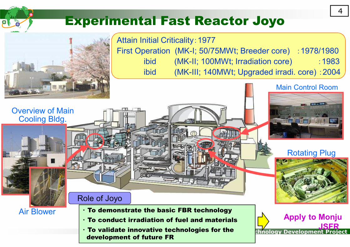
Experimental Fast Reactor Joyo
Apply to Monju
JSFR
Overview of Main Cooling Bldg.
Air Blower
Main Control Room
Rotating Plug
・ To demonstrate the basic FBR technology
・ To conduct irradiation of fuel and materials
・ To validate innovative technologies for the
development of future FR
Attain Initial Criticality:1977
First Operation (MK-I; 50/75MWt; Breeder core) :1978/1980
ibid (MK-II; 100MWt; Irradiation core) :1983
ibid (MK-III; 140MWt; Upgraded irradi. core) :2004
Role of Joyo

Fast Reactor Cycle Technology Development Project
5
Safety of Joyo in case of a tsunami and blackout
38m
Approx. 300m
• Joyo is located at 38 meters above
sea level.
• The heat is released into air in the
secondary loop finally.
• Decay heat can be removed by a
natural circulation of sodium.
Natural circulation
Location of Joyo
Ocean
~~
Air
46th TWG-FR Annual Meeting, May 21-24, IAEA HQ, Vienna, Austria

Fast Reactor Cycle Technology Development Project
6
UCS retrieval device (cask)
UCS
MARICO-2 retrieval device
Replace UCS Retrieve MARICO-2
In-vessel observation device
Small rotating plug
Transfer pot
MARICO-2Finger
MARICO: Material testing rigs with temperature control
Replace UCS and Retrieve MARICO-2
46th TWG-FR Annual Meeting, May 21-24, IAEA HQ, Vienna, Austria
Fast Reactor Cycle Technology Development Project
7
Screw Jack-up
Equipment
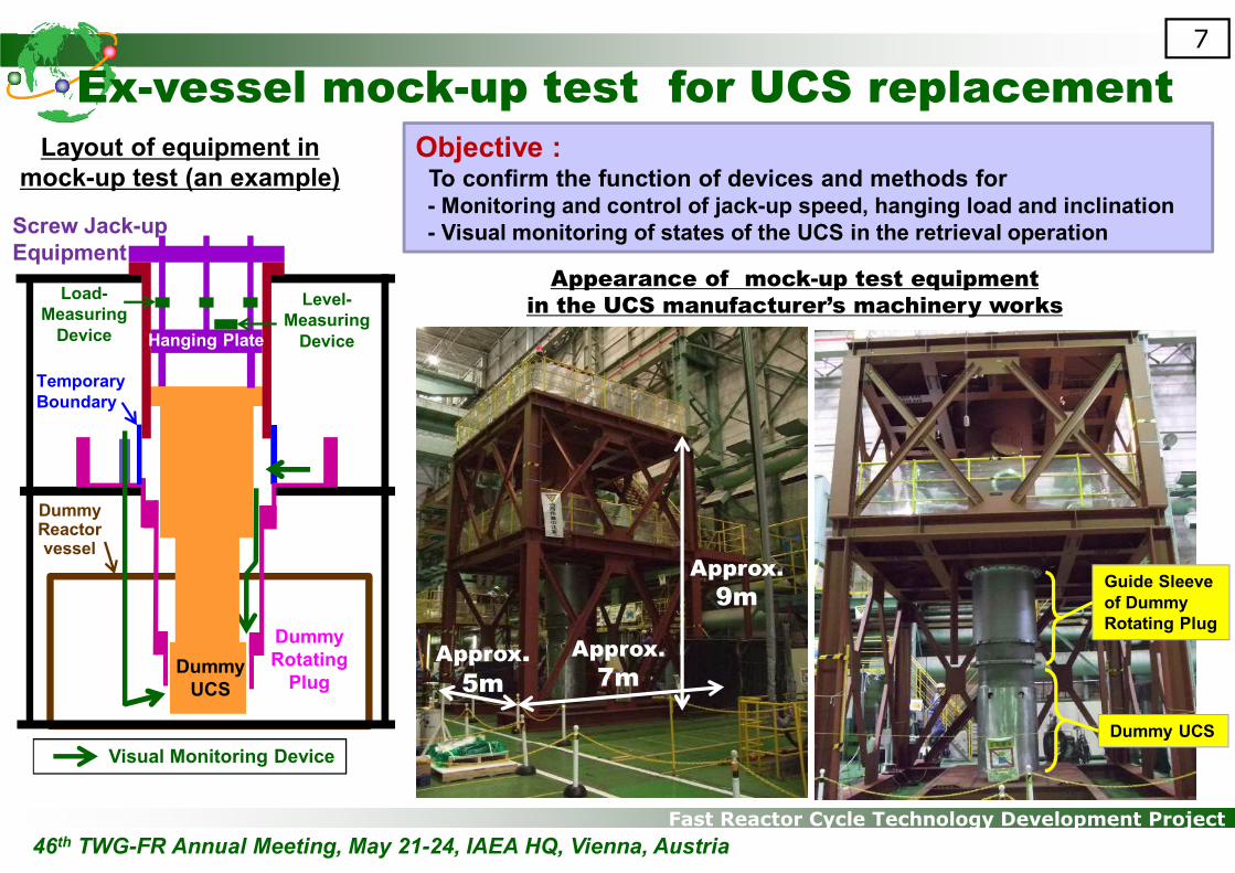
Layout of equipment in
mock-up test (an example) Objective :To confirm the function of devices and methods for- Monitoring and control of jack-up speed, hanging load and inclination
- Visual monitoring of states of the UCS in the retrieval operation
UCS
模擬体
Appearance of mock-up test equipment
in the UCS manufacturer’s machinery works
Approx.
9m
Approx.
7mApprox.
5mDummy
UCS
DummyReactorvessel
Dummy
Rotating
Plug
Temporary
Boundary
Load-
Measuring
Device
Level-
Measuring
DeviceHanging Plate
Visual Monitoring Device
Dummy UCS
Guide Sleeve
of Dummy
Rotating Plug
Ex-vessel mock-up test for UCS replacement
46th TWG-FR Annual Meeting, May 21-24, IAEA HQ, Vienna, Austria
Fast Reactor Cycle Technology Development Project
8
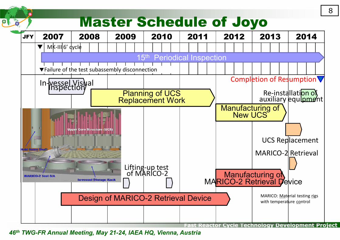
JFY 2007 2008 2009 2010 2011 2012 2013 2014
15th Periodical Inspection
Design of MARICO-2 Retrieval Device
Planning of UCS Replacement Work
Manufacturing ofNew UCS
In-vessel Visual Inspection
UCS Replacement
MARICO-2 Retrieval
Lifting-up testof MARICO-2
▼ MK-III 6’ cycle
Manufacturing ofMARICO-2 Retrieval Device
▼Failure of the test subassembly disconnection
Re-installation of auxiliary equipment
Completion of Resumption
MARICO: Material testing rigs
with temperature control
Master Schedule of Joyo
46th TWG-FR Annual Meeting, May 21-24, IAEA HQ, Vienna, Austria

Fast Reactor Cycle Technology Development Project
9
3. Prototype Fast Reactor MONJU
46th TWG-FR Annual Meeting, May 21-24, IAEA HQ, Vienna, Austria
Current Status and Future Plan
Fast Reactor Cycle Technology Development Project
10
Sodium leak detection
and monitoring system
Modification of 2ry
sodium piping
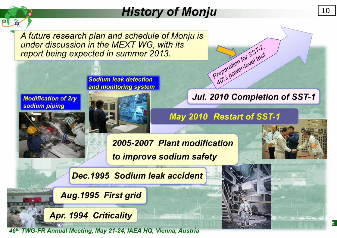
Dec.1995 Sodium leak accident
2005-2007 Plant modification
to improve sodium safety
Aug.1995 First grid
Apr. 1994 Criticality
May 2010 Restart of SST-1
Jul. 2010 Completion of SST-1
A future research plan and schedule of Monju is under discussion in the MEXT WG, with its report being expected in summer 2013.
46th TWG-FR Annual Meeting, May 21-24, IAEA HQ, Vienna, Austria
History of Monju

Fast Reactor Cycle Technology Development Project
11
46th TWG-FR Annual Meeting, May 21-24, IAEA HQ, Vienna, Austria
Overview of System Start-up Test (SST)
Fast Reactor Cycle Technology Development Project
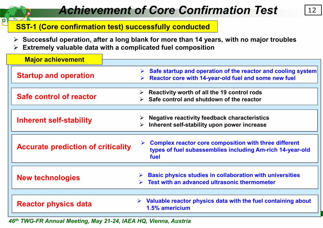
12Achievement of Core Confirmation Test
� Safe startup and operation of the reactor and cooling system
� Reactor core with 14-year-old fuel and some new fuelStartup and operation
� Reactivity worth of all the 19 control rods
� Safe control and shutdown of the reactorSafe control of reactor
Inherent self-stability � Negative reactivity feedback characteristics
� Inherent self-stability upon power increase
� Complex reactor core composition with three different
types of fuel subassemblies including Am-rich 14-year-old
fuel
Accurate prediction of criticality
New technologies � Basic physics studies in collaboration with universities
� Test with an advanced ultrasonic thermometer
Reactor physics data
Major achievement
� Valuable reactor physics data with the fuel containing about
1.5% americium
� Successful operation, after a long blank for more than 14 years, with no major troubles
� Extremely valuable data with a complicated fuel composition
SST-1 (Core confirmation test) successfully conducted
46th TWG-FR Annual Meeting, May 21-24, IAEA HQ, Vienna, Austria
Fast Reactor Cycle Technology Development Project
13
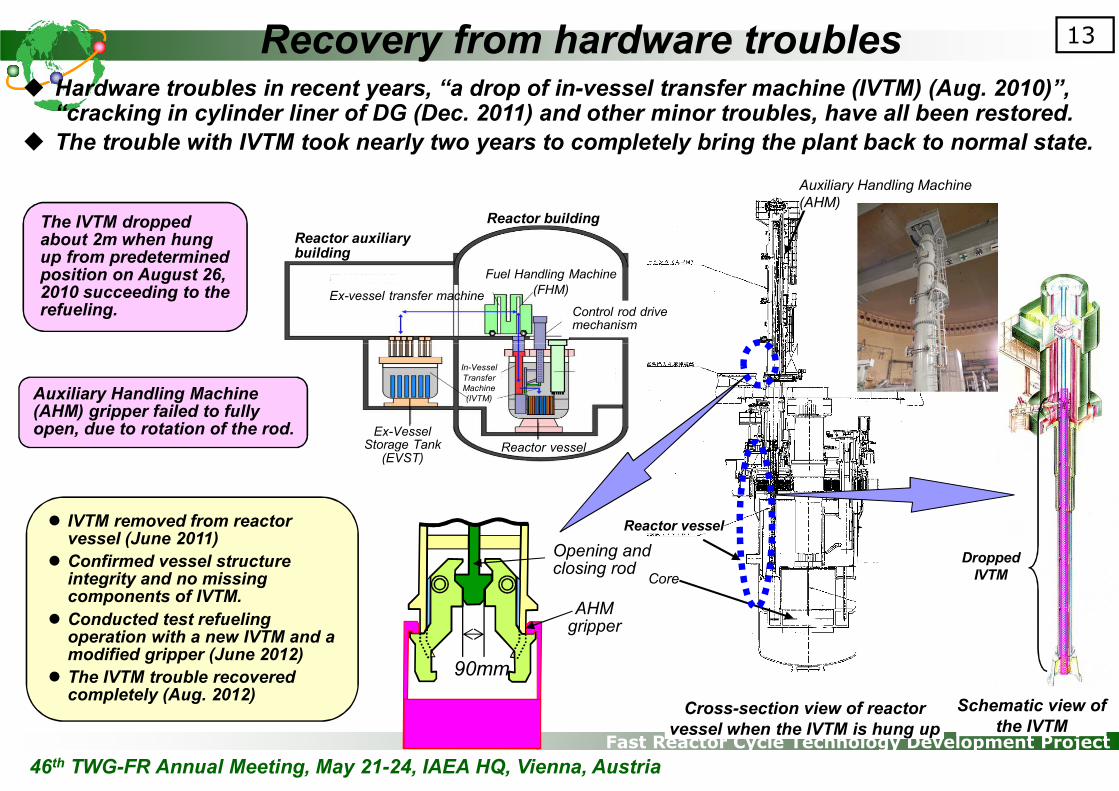
� Hardware troubles in recent years, “a drop of in-vessel transfer machine (IVTM) (Aug. 2010)”, “cracking in cylinder liner of DG (Dec. 2011) and other minor troubles, have all been restored.
� The trouble with IVTM took nearly two years to completely bring the plant back to normal state.
Reactor vessel
Core
Cross-section view of reactor
vessel when the IVTM is hung up
Dropped
IVTM
Schematic view of
the IVTM
AHMgripper
90mm
Auxiliary Handling Machine (AHM) gripper failed to fully open, due to rotation of the rod.
Ex-vessel transfer machine
Reactor building
In-Vessel
Transfer
Machine
(IVTM)
The IVTM dropped about 2m when hung up from predetermined position on August 26, 2010 succeeding to the refueling.
� IVTM removed from reactor vessel (June 2011)
� Confirmed vessel structure integrity and no missing components of IVTM.
� Conducted test refueling operation with a new IVTM and a modified gripper (June 2012)
� The IVTM trouble recovered completely (Aug. 2012)
Auxiliary Handling Machine
(AHM)
Reactor auxiliary building
Fuel Handling Machine
(FHM)
Control rod drivemechanism
Ex-Vessel Storage Tank
(EVST)Reactor vessel
Opening andclosing rod
46th TWG-FR Annual Meeting, May 21-24, IAEA HQ, Vienna, Austria
Recovery from hardware troubles
Fast Reactor Cycle Technology Development Project
14Features of Monju and Measures for SBO
around
17mmmm
IHX
Reactorvessel
Air cooler
Heat source(Core)
Heat sink(Air cooler)
Power-supply vehicle
Power supply
Ingenious layout of equipments and pipes
Heat to be released to atmosphere
Air
Center of reactor
around
7mmmm
T.P.+0m ▽▽▽▽
T.P.-6.5m
T.P.+5.2m▽▽▽▽
Intake
T.P.+21m
Reactorbuilding
Reactor auxiliary building
6.4mT.P.+31m
T.P.
+42.8m
Breakwater Curtain wall
Screen pump room
Diesel building
EVST
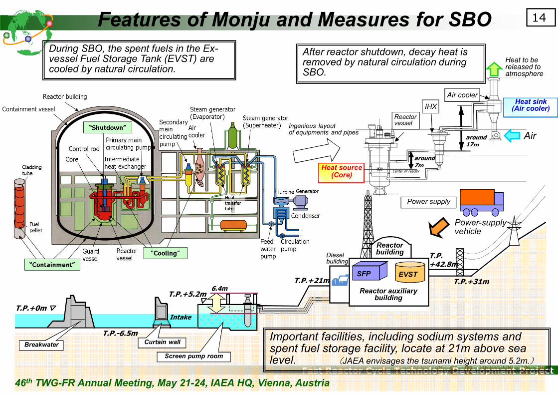
Important facilities, including sodium systems and spent fuel storage facility, locate at 21m above sea level. (JAEA envisages the tsunami height around 5.2m.)
During SBO, the spent fuels in the Ex-vessel Fuel Storage Tank (EVST) are cooled by natural circulation.
After reactor shutdown, decay heat is removed by natural circulation during SBO.
SFP
46th TWG-FR Annual Meeting, May 21-24, IAEA HQ, Vienna, Austria

Fast Reactor Cycle Technology Development Project
15Post-Fukushima Safety Improvement in Monju
Sea level +0m ▽▽▽▽
-6.5m
++++5.2m▽▽▽▽
取水口取水口取水口取水口
6.4m
(6) Assurance of decay heat removal and ultimate heat sink� Inherent safety features of natural-convection decay heat removal have
been re-evaluated for both the core and EVST
� Forced-convection cooling has been made available as well, with electricity from the power supply vehicle.
+21m
(3) Sealing of sea-water piping
The penetrations to the buildings were water-tightened.
(2) Water supply to spent fuel pool
The fuel is cooled in EVST and then in fuel pool. The power in the pool is low enough to avoid boiling, but water supply is prepared using fire engines.
<Earthquake>
Fukushima-Daiichi accident and consequence
� Reactor shutdown successfully� Emergency DGs actuated normally� Reactor cooling systems operated as intended� Loss of off-site power supply due to failure of power
transmission line
� Essential power equipment such as DGs, switch boards, and butteries were all flooded
� Seawater pumps failure, leading to loss of ultimate heat sink
� Station black-out (loss of off-site and on-site DG power)
Long-lasting station blackout and loss of ultimate heat sink conditions led to severe fuel damage, loss of confinement capability, and serious off-site release of radioactive materials.
Safety measures implemented in LWRs
� Measures under the SBO condition� Diverse power supply for plant monitoring
� Measures for loss of cooling in fuel pool� Preparation of water supply to spent fuel
pool� Measures to avoid seawater intrusion
� Water-tightening of seawater piping
Seawater pumpsCurtain wallBreakwater
afterbefore
(4) Measures for cooling� Insulators were packaged
for easy manual access to the valves in the auxiliary cooling system (air coolers).
(5) Inspection and drills� Repetition of drills� Manuals
Reactor bldg.
+42.8m
DG bldg.
Reactor auxiliary bldg.
Emergency
DGs (3)
Control room,
power
systems, etc.
Fuel pool
(1) Disposition of power vehicles
Buttery charging
Butteries
EVST cooling
Plant monitoringPlant
protection
systems
Control room
air conditioning
Air coolers
Vehicles (300kVA x 2)A larger-capacity power vehicle with gas turbine (4000kVA) is to be disposed in 2013.
<Tsunami>
<Consequence>
46th TWG-FR Annual Meeting, May 21-24, IAEA HQ, Vienna, Austria
Fast Reactor Cycle Technology Development Project
16Decay heat removal from the core
seawater
DG
Reactor BuildingPump
Shutdown
Pump
Shutdown
Air Cooler Blower Shutdown
Air Cooler Blower Shutdown
ContainmentVessel
Primary MainCirculation Pump
Primary Sodium
N2 Gas
IntermediateHeat Exchanger
Fuel Control Rod
Guard VesselReactor Vessel
Secondary MainCirculation Pump
Air Cooler
SecondarySodium
Steam GeneratorInlet Stop Valve(Closed)
Air CoolerOutlet Stop Valve
(Opened)seawater
DG
Reactor BuildingPump
Shutdown
Pump
Shutdown
Air Cooler Blower Shutdown
Air Cooler Blower Shutdown
ContainmentVessel
Primary MainCirculation Pump
Primary Sodium
N2 Gas
IntermediateHeat Exchanger
Fuel Control Rod
Guard VesselReactor Vessel
Secondary MainCirculation Pump
Air Cooler
SecondarySodium
Steam GeneratorInlet Stop Valve(Closed)
Air CoolerOutlet Stop Valve
(Opened)
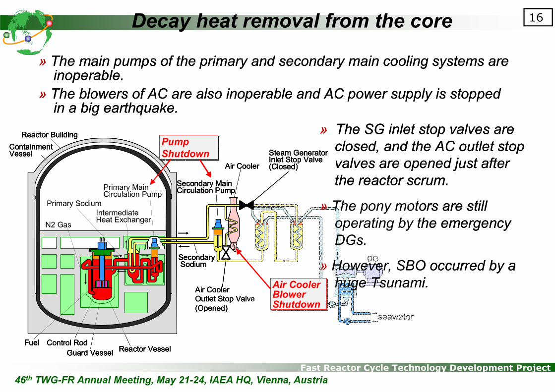
» The main pumps of the primary and secondary main cooling systems are inoperable.
» The blowers of AC are also inoperable and AC power supply is stopped in a big earthquake.
» The SG inlet stop valves are
closed, and the AC outlet stop
valves are opened just after
the reactor scrum.
» The pony motors are still
operating by the emergency
DGs.
» However, SBO occurred by a
huge Tsunami.
seawater
DG
Reactor BuildingPump
Shutdown
Pump
Shutdown
Air Cooler Blower Shutdown
Air Cooler Blower Shutdown
ContainmentVessel
Primary MainCirculation Pump
Primary Sodium
N2 Gas
IntermediateHeat Exchanger
Fuel Control Rod
Guard VesselReactor Vessel
Secondary MainCirculation Pump
Air Cooler
SecondarySodium
Steam GeneratorInlet Stop Valve(Closed)
Air CoolerOutlet Stop Valve
(Opened)seawater
DG
Reactor BuildingPump
Shutdown
Pump
Shutdown
Air Cooler Blower Shutdown
Air Cooler Blower Shutdown
ContainmentVessel
Primary MainCirculation Pump
Primary Sodium
N2 Gas
IntermediateHeat Exchanger
Fuel Control Rod
Guard VesselReactor Vessel
Secondary MainCirculation Pump
Air Cooler
SecondarySodium
Steam GeneratorInlet Stop Valve(Closed)
Air CoolerOutlet Stop Valve
(Opened)
» The main pumps of the primary and secondary main cooling systems are inoperable.
» The blowers of AC are also inoperable and AC power supply is stopped in a big earthquake.
» The SG inlet stop valves are
closed, and the AC outlet stop
valves are opened just after
the reactor scrum.
» The pony motors are still
operating by the emergency
DGs.
» However, SBO occurred by a
huge Tsunami.
46th TWG-FR Annual Meeting, May 21-24, IAEA HQ, Vienna, Austria

Fast Reactor Cycle Technology Development Project
17DHR from core under SBO (long term)
� Coolant temperature is stably reduced below 250ºC in 3 days.
� DHR by natural convection is possible only in 1 loop (out of 3)
� When a DG is recovered, coolant temperature is further stabilized
� Fuel and cladding temperatures stay below the safety criteria
� Conclusions unchanged even with more pessimistic assumptions
(a) Primary Heat Transport System
0
20
40
60
80
100
120
140
160
150
200
250
300
350
400
450
500
550
0 1 2 3 4 5 6 7
流
量
(
%
)
温
度
(
℃
)
時間(日)津波来襲津波来襲津波来襲津波来襲地震発生地震発生地震発生地震発生 ディーゼル発電機1台復旧ディーゼル発電機1台復旧ディーゼル発電機1台復旧ディーゼル発電機1台復旧
RV outlet
RV inlet
Flow rate
Natural circulation
Forced circulation
Te
mp
era
ture
(ºC
)
Flo
w r
ate
(%
)
160
140
120
100
80
60
40
20
00 1 2 3 4 5 6 7
Time (day)
550
500
450
400
350
300
250
200
150
Pony motor restarted
Earthquake~SBO
0
20
40
60
80
100
120
140
160
150
200
250
300
350
400
450
500
550
0 1 2 3 4 5 6 7
流
量
(
%
)
温
度
(
℃
)
時間(日)津波来襲津波来襲津波来襲津波来襲地震発生地震発生地震発生地震発生 ディーゼル発電機1台復旧ディーゼル発電機1台復旧ディーゼル発電機1台復旧ディーゼル発電機1台復旧
(b) Secondary Heat Transport System
Time (day)0 1 2 3 4 5 6 7
550
500
450
400
350
300
250
200
150
Natural circulation
Forced circulation
Te
mp
era
ture
(ºC
)
160
140
120
100
80
60
40
20
0
Flo
w r
ate
(%
)
AC outlet
AC inlet
Flow rate
Pony motor restarted
Earthquake~SBO
(a) Primary Heat Transport System
0
20
40
60
80
100
120
140
160
150
200
250
300
350
400
450
500
550
0 1 2 3 4 5 6 7
流
量
(
%
)
温
度
(
℃
)
時間(日)津波来襲津波来襲津波来襲津波来襲地震発生地震発生地震発生地震発生 ディーゼル発電機1台復旧ディーゼル発電機1台復旧ディーゼル発電機1台復旧ディーゼル発電機1台復旧
RV outlet
RV inlet
Flow rate
Natural circulation
Forced circulation
Te
mp
era
ture
(ºC
)
Flo
w r
ate
(%
)
160
140
120
100
80
60
40
20
00 1 2 3 4 5 6 7
Time (day)
550
500
450
400
350
300
250
200
150
Pony motor restarted
Earthquake~SBO
0
20
40
60
80
100
120
140
160
150
200
250
300
350
400
450
500
550
0 1 2 3 4 5 6 7
流
量
(
%
)
温
度
(
℃
)
時間(日)津波来襲津波来襲津波来襲津波来襲地震発生地震発生地震発生地震発生 ディーゼル発電機1台復旧ディーゼル発電機1台復旧ディーゼル発電機1台復旧ディーゼル発電機1台復旧
(b) Secondary Heat Transport System
Time (day)0 1 2 3 4 5 6 7
550
500
450
400
350
300
250
200
150
Natural circulation
Forced circulation
Te
mp
era
ture
(ºC
)
160
140
120
100
80
60
40
20
0
Flo
w r
ate
(%
)
AC outlet
AC inlet
Flow rate
Pony motor restarted
Earthquake~SBO
0
20
40
60
80
100
120
140
160
150
200
250
300
350
400
450
500
550
0 1 2 3 4 5 6 7
流
量
(
%
)
温
度
(
℃
)
時間(日)津波来襲津波来襲津波来襲津波来襲地震発生地震発生地震発生地震発生 ディーゼル発電機1台復旧ディーゼル発電機1台復旧ディーゼル発電機1台復旧ディーゼル発電機1台復旧
(b) Secondary Heat Transport System
Time (day)0 1 2 3 4 5 6 7
550
500
450
400
350
300
250
200
150
Natural circulation
Forced circulation
Te
mp
era
ture
(ºC
)
160
140
120
100
80
60
40
20
0
Flo
w r
ate
(%
)
AC outlet
AC inlet
Flow rate
Pony motor restarted
Earthquake~SBO
46th TWG-FR Annual Meeting, May 21-24, IAEA HQ, Vienna, Austria
Fast Reactor Cycle Technology Development Project
18Comprehensive safety assessment
Station Blackout
Plant
Shut-down
Emergency
Power Supply
Cooling
Down
Natural Circulation
CoolingDown
Failure
Core
Damage
1.25*
>2.2* 1.79* 1.53*
Diesel
GeneratorStart-up
1.25*
1.86*
: cliff edge
Air Cooler
Forced Circulation
Success
FailureFailure Failure
Failure
Success Success Success
Success
Tolerance in design-
basis earthquake
acceleration(760 gal)
*:
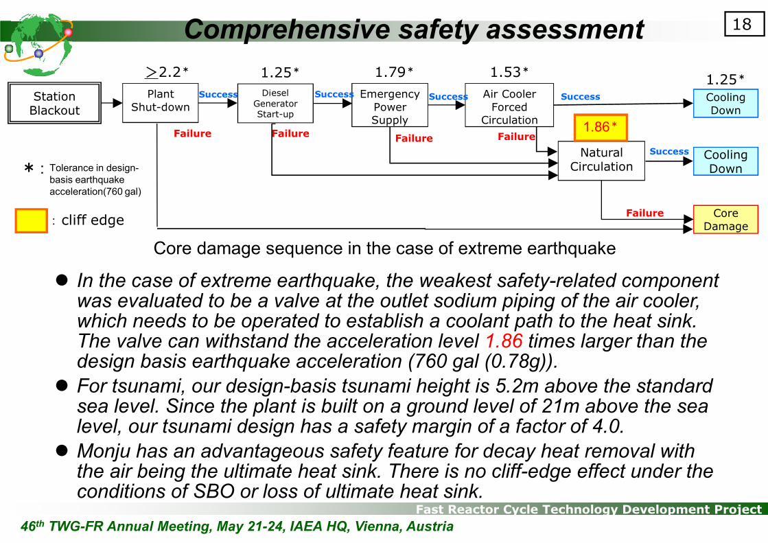
Core damage sequence in the case of extreme earthquake
� In the case of extreme earthquake, the weakest safety-related component was evaluated to be a valve at the outlet sodium piping of the air cooler, which needs to be operated to establish a coolant path to the heat sink. The valve can withstand the acceleration level 1.86 times larger than the design basis earthquake acceleration (760 gal (0.78g)).
� For tsunami, our design-basis tsunami height is 5.2m above the standard sea level. Since the plant is built on a ground level of 21m above the sea level, our tsunami design has a safety margin of a factor of 4.0.
� Monju has an advantageous safety feature for decay heat removal with the air being the ultimate heat sink. There is no cliff-edge effect under the conditions of SBO or loss of ultimate heat sink.
46th TWG-FR Annual Meeting, May 21-24, IAEA HQ, Vienna, Austria

Fast Reactor Cycle Technology Development Project
19
� In a wake of Fukushima accident, national law and regulations for ascertain the safety of nuclear installations have been amended significantly in Japan.
� Although the safety standard under development is to be applied to LWRs, but is to be considered also in Monju, taking detailed consideration of the differences in safety features and design characteristics between LWRs and sodium-cooled fast reactors.
� The future plan of SSTs and operation of Monju will be judged based on a research plan developed by the MEXT Working Group through 2013.
� In parallel to this, we will keep our effort to improve the safety of Monju taking the lessons learned from Fukushima. We believe the risk level of Monju can be kept low and with added accident management measures to further improve safety the level will be made much lower.
� The roles of Monju as a prototype continue to be important. In addition, it must be emphasized that some of the international joint research programs using Monju are still actively continuing, because the reactor is one of the very few fast reactor plants that are operable today.
� Thus Monju is expected to play a role as an international asset to provide research facility and knowledge/technology transfer to future generations.
46th TWG-FR Annual Meeting, May 21-24, IAEA HQ, Vienna, Austria
Prospect for future

Fast Reactor Cycle Technology Development Project
4. SFR Development in Japan
20
46th TWG-FR Annual Meeting, May 21-24, IAEA HQ, Vienna, Austria
Fast Reactor Cycle Technology Development Project
21
SFR Development in Japan99 00 01 02 03 04 05 06 07 08 09 10 11 12 13 14 15
FS P-I
FS P-II Earthquake and 1F accident
FaCT P-I
(FaCT P-II)
Safety Enhance
SDC SDG
(JFY: April to March)
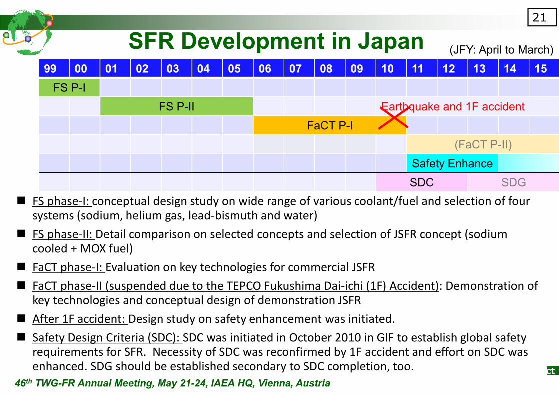
� FS phase-I: conceptual design study on wide range of various coolant/fuel and selection of four systems (sodium, helium gas, lead-bismuth and water)
� FS phase-II: Detail comparison on selected concepts and selection of JSFR concept (sodium cooled + MOX fuel)
� FaCT phase-I: Evaluation on key technologies for commercial JSFR
� FaCT phase-II (suspended due to the TEPCO Fukushima Dai-ichi (1F) Accident): Demonstration of key technologies and conceptual design of demonstration JSFR
� After 1F accident: Design study on safety enhancement was initiated.
� Safety Design Criteria (SDC): SDC was initiated in October 2010 in GIF to establish global safety requirements for SFR. Necessity of SDC was reconfirmed by 1F accident and effort on SDC was enhanced. SDG should be established secondary to SDC completion, too.
46th TWG-FR Annual Meeting, May 21-24, IAEA HQ, Vienna, Austria
Fast Reactor Cycle Technology Development Project
Secondary pump
SG
Integratedpump-IHX
Reactor Vessel
Reactor Core
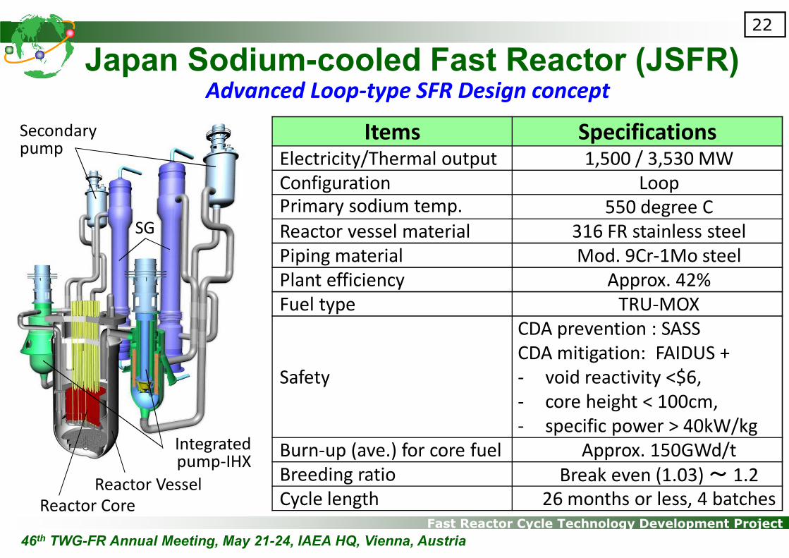
Japan Sodium-cooled Fast Reactor (JSFR)
22
Advanced Loop-type SFR Design concept
Items SpecificationsElectricity/Thermal output 1,500 / 3,530 MW
Configuration LoopPrimary sodium temp. 550 degree C
Reactor vessel material 316 FR stainless steel
Piping material Mod. 9Cr-1Mo steel
Plant efficiency Approx. 42%
Fuel type TRU-MOX
Safety
CDA prevention : SASS
CDA mitigation: FAIDUS +
- void reactivity <$6,
- core height < 100cm,
- specific power > 40kW/kg
Burn-up (ave.) for core fuel Approx. 150GWd/t
Breeding ratio Break even (1.03) ~ 1.2
Cycle length 26 months or less, 4 batches
46th TWG-FR Annual Meeting, May 21-24, IAEA HQ, Vienna, Austria

Fast Reactor Cycle Technology Development Project
23
SDC key concept� Safety Goals in Gen-IV reactors
� Excel in Operational Safety and Reliability
� Very low likelihood & degree of reactor core damage
� Elimination of the need for offsite emergency response
� Key Safety Approach� Applying reinforced Defence-in-Depth (DiD)
� Built-in, and not by add-on
� Measures for prevention & mitigation of Severe Accident (SA) in DiD Level 4
� Passive safety utilization for DEC
Design Basis
Level 1: Prevention of abnormal operation and failures
Level 2: Control of abnormal operation and detection of failures
Level 3: Control of accidents within the design basis
Design Extension
Condition (DEC)
Level 4: Control of severe conditions including prevention of accident
progression and mitigation of the consequences of a severe accident
Off-site response Level 5: Mitigation of radiological consequences of significant external
releases of radioactive materials
* Defence-In-Depth, ** Severe Accident46th TWG-FR Annual Meeting, May 21-24, IAEA HQ, Vienna, Austria

Fast Reactor Cycle Technology Development Project
24
Hypothetical 1F conditions on JSFR version 2010- Power supply and CCWS/SCWS -
<Conventional system>
DHRS safety grade components
� Pony motor on the primary pump
� DHRS 2nd circuit EMP
� Blowers for air cooler
Emergency DG
Component cooling
water system (CCWS)
Sea water cooling system
(SWCS)
depend depend
<JSFR with Natural circulation DHRS>
DHRS safety grade components
� Air cooler damper Emergency battery (DC power)
� JSFR does not require quick emergency power activation because of full NC
DHRS and is able to introduces emergency gas turbine generator(GTG) with air
cooling which requires a few dozen seconds for activation.
� JSFR DHRS is independent electric supply thanks for NC DHRS except for
dumper control of air cooler.
� JSFR CCWS and SWCS are non-safety grade as in 2010 design.
depend
Affected by tsunami
46th TWG-FR Annual Meeting, May 21-24, IAEA HQ, Vienna, Austria
Fast Reactor Cycle Technology Development Project
25
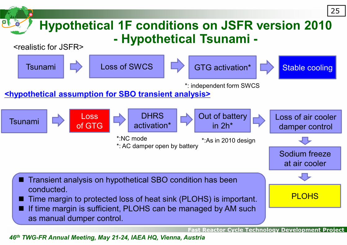
Hypothetical 1F conditions on JSFR version 2010- Hypothetical Tsunami -
Tsunami Loss of SWCS
<realistic for JSFR>
<hypothetical assumption for SBO transient analysis>
GTG activation* Stable cooling
*: independent form SWCS
TsunamiLoss
of GTG
DHRS
activation*
*:NC mode
*: AC damper open by battery
Out of battery
in 2h*Loss of air cooler
damper control
Sodium freeze
at air cooler
PLOHS
*:As in 2010 design
� Transient analysis on hypothetical SBO condition has been
conducted.
� Time margin to protected loss of heat sink (PLOHS) is important.
� If time margin is sufficient, PLOHS can be managed by AM such
as manual dumper control.
46th TWG-FR Annual Meeting, May 21-24, IAEA HQ, Vienna, Austria

Fast Reactor Cycle Technology Development Project
26
Hypothetical 1F conditions on JSFR version 2010- Hypothetical SBO transient analysis -
� SBO analysis shows sufficient time margin to initiate AM
Fast Reactor Cycle Technology Development Project
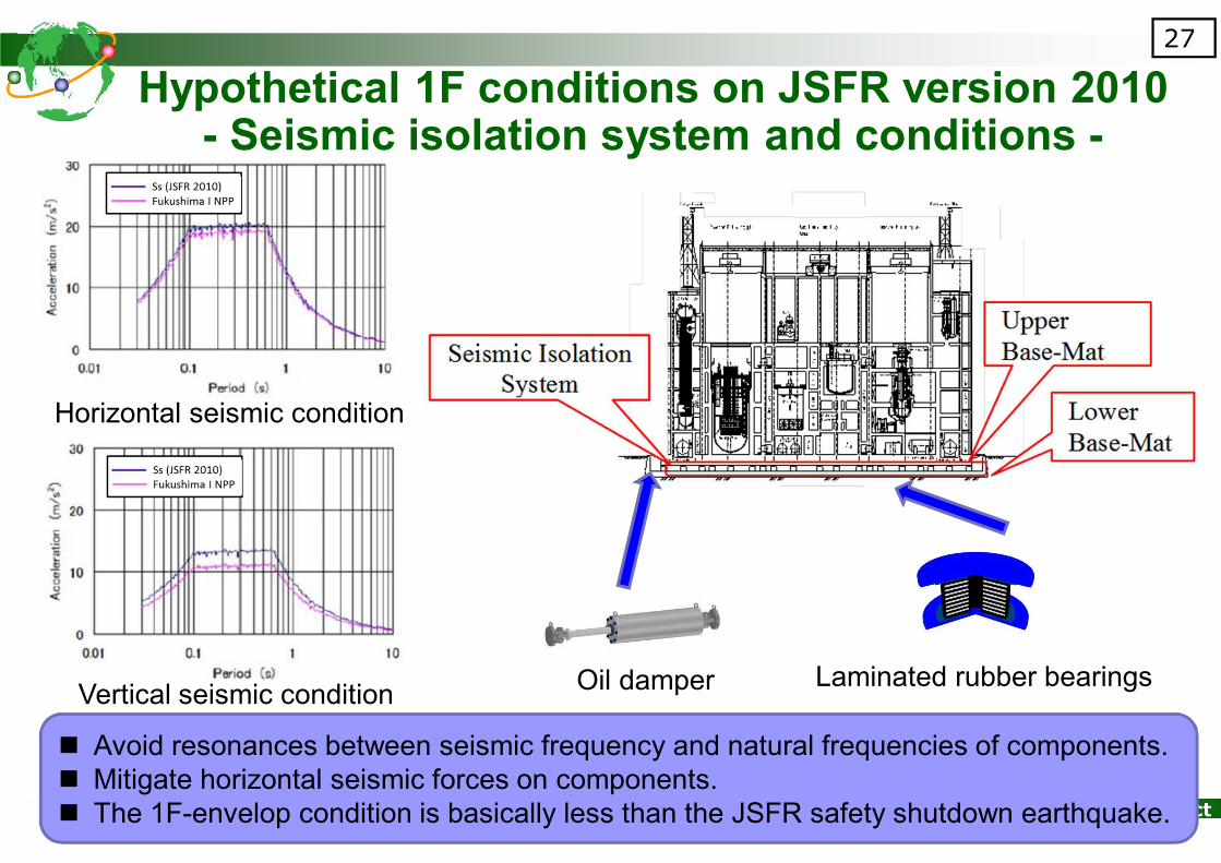
27
Hypothetical 1F conditions on JSFR version 2010- Seismic isolation system and conditions -
Oil damper Laminated rubber bearings
� Avoid resonances between seismic frequency and natural frequencies of components.
� Mitigate horizontal seismic forces on components.
� The 1F-envelop condition is basically less than the JSFR safety shutdown earthquake.
Horizontal seismic condition
Vertical seismic condition

Fast Reactor Cycle Technology Development Project
28
Hypothetical 1F conditions on JSFR version 2010- Seismic margins -
� The 1F-envelop condition has been used in this seismic evaluation.
� Seismic design margins of JSFR ver. 2010 are sufficient for 1F seismic conditions.
Component Item Margin
RVBuckling 2.4
Control rod insertion capability 1.7
Integrated-IHX BucklingY piece 22.8
Skirt 50.0
SG BucklingSkirt 21.1
Main Body 20.9
Primary pipingStress (Hot-leg) Support piping 17.6
Stress (Cold-leg) Elbow center 5.3
Secondary pipingStress (Hot-leg) Elbow center 13.7
Stress (Cold-leg) Elbow center 47.2
DRACS secondary pipingStress (Hot-leg) Elbow center 4.7
Stress (Cold-leg) Elbow center 4.3
PRACS secondary pipingStress (Hot-leg) T piping 3.9
Stress (Cold-leg) T piping 4.7
EVST Stress
Rotating rack 2.1
Inner tank 2.5
Outer tank 23.8
EVTM Stress
Main body 23.4
Rail hook 6.4
Locator pin 1.9
46th TWG-FR Annual Meeting, May 21-24, IAEA HQ, Vienna, Austria
Fast Reactor Cycle Technology Development Project
29
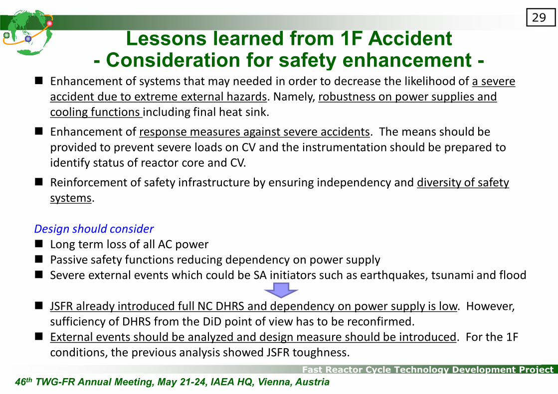
Lessons learned from 1F Accident- Consideration for safety enhancement -
� Enhancement of systems that may needed in order to decrease the likelihood of a severe
accident due to extreme external hazards. Namely, robustness on power supplies and
cooling functions including final heat sink.
� Enhancement of response measures against severe accidents. The means should be
provided to prevent severe loads on CV and the instrumentation should be prepared to
identify status of reactor core and CV.
� Reinforcement of safety infrastructure by ensuring independency and diversity of safety
systems.
Design should consider
� Long term loss of all AC power
� Passive safety functions reducing dependency on power supply
� Severe external events which could be SA initiators such as earthquakes, tsunami and flood
� JSFR already introduced full NC DHRS and dependency on power supply is low. However,
sufficiency of DHRS from the DiD point of view has to be reconfirmed.
� External events should be analyzed and design measure should be introduced. For the 1F
conditions, the previous analysis showed JSFR toughness.
46th TWG-FR Annual Meeting, May 21-24, IAEA HQ, Vienna, Austria

Fast Reactor Cycle Technology Development Project
30
Lessons learned from 1F Accident- Situations to be practically eliminated -
<ATWS>
� In-balance of power and cooling might causes core damage within a shorter time period.
� Relocation of damaged core could cause potential mechanical energy release.
� Severe mechanical energy release due to coherent sodium boiling or molten fuel compaction,
failure of decay heat removal from degraded core in ATWS type events
� JSFR already meet this requirement as JSFR 2010 version
<LOHRS>
� Decay heat is at a few percent of the nominal power, the temperature of the reactor coolant
system would be slow with sufficient time margin to make recovery action for failed DHRSs
and/or implementation of back up cooling measures.
� If no heat sink is available, core and coolant boundary failure might occur due to high
temperature causing significant thermal loads not to cope with on the containment.
� Significant core damage in LOHRS type events
� Even though JSFR has full NC DHRS, additional DHRS for DEC which is independent of DBA
DHRS is under discussion.
46th TWG-FR Annual Meeting, May 21-24, IAEA HQ, Vienna, Austria
Fast Reactor Cycle Technology Development Project
31
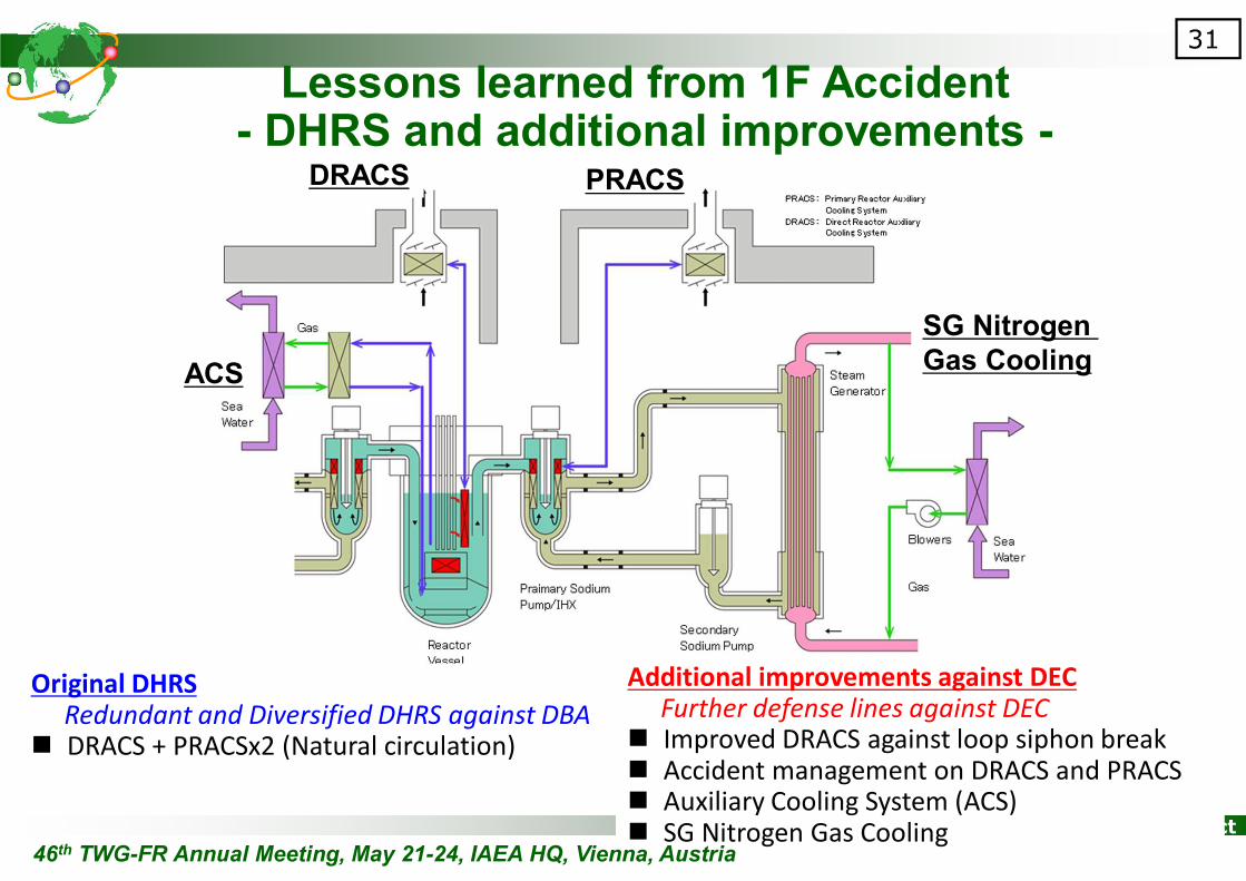
Lessons learned from 1F Accident- DHRS and additional improvements -
Original DHRS
Redundant and Diversified DHRS against DBA� DRACS + PRACSx2 (Natural circulation)
ACS
DRACS PRACS
SG Nitrogen
Gas Cooling
Additional improvements against DEC
Further defense lines against DEC� Improved DRACS against loop siphon break� Accident management on DRACS and PRACS� Auxiliary Cooling System (ACS)� SG Nitrogen Gas Cooling
46th TWG-FR Annual Meeting, May 21-24, IAEA HQ, Vienna, Austria

Fast Reactor Cycle Technology Development Project
Thank you for your attention!

Fast Reactor Cycle Technology Development Project
Appendix
46th TWG-FR Annual Meeting, May 21-24, IAEA HQ, Vienna, Austria

Fast Reactor Cycle Technology Development Project
34
1. Only by Monju 2. Reasonable by Monju 3. Possible without Monju
A. E
ssentialS
FR
technolo
gy
A-1
� Core design and management with
fuel containing higher-order Pu/Am .
� Design and evaluation of loop-type
cooling system, hot reactor vessel,
fuel handling system, etc.
� In-service-inspection devices for R/V
and primary cooling piping.
� Maintenance of primary cooling
system.
� Sever accident evaluation.
� Design and evaluation of heat
removal by Natural convection in
loop-type cooling system.
� Design and evaluation of
Sodium/Water reaction prevention
and mitigation.
A-2
� Design of large scale fuel
assembly
� Design and evaluation of large
scale main sodium components.
� Instrumentation for sodium leakage,
Sodium/Water reaction & failed fuel
detection.
� In-service-inspection devices for
Heat exchange pipe of Steam
generator
� Sodium handling technique.
� Maintenance of Fuel handling
system.
A-3
� Design and evaluation of
components under high
temperature.
� Prevention and mitigation
design of sever accident in
large scale SFR
B. U
sefu
l
SF
R
technolo
gy B-1
� Design and evaluation of transient
and control characteristics of the
steam/water system.
B-2
� Design and evaluation of steam
generators.
B-3
� Design and evaluation of
secondary pumps.
A. N
on S
FR
technolo
gy C-1
� Design of support systems (utilities,
air, etc.)
� Turbine and generators
C-2
(none)
C-3
(none)
Imp
orta
nc
e o
f R
&D
Su
bje
cts
Necessity of using Monju
46th TWG-FR Annual Meeting, May 21-24, IAEA HQ, Vienna, Austria
Prioritization on Monju R&Ds (example)

Fast Reactor Cycle Technology Development ProjectJAEA is proposing AtheNa-SA experiments for various DHRS in GIF framework.
International cooperation on SA cooling measures
・Dimension:130m x 62m x 55m
・Total floor area: 11,000m2
・Sodium inventory: 240ton
� Criteria to practical elimination of LOHRS and sufficient design measures should be discussed
internationally.
� Design measures and design tools should be developed and validated internationally regarding
objectivity and cross-check.
AtheNa facility
46th TWG-FR Annual Meeting, May 21-24, IAEA HQ, Vienna, Austria