Embed Size (px)
Citation preview
,:1
fRITZ ~NGfNEE;\:':iG LABORATORV)LEHIGH UNIVERSITY •
BETHLEHEM, PENNSYLVANIA
PROGRESS REPOHT ON
RIGID STEEL FRAME INVESTIGATION
by Winston E. Black·----~~-~-~-~~----~--
1. SYNOPSIS
b The results ot the tirst year's investigation ot'a two
year study or steel rigid trames is presented in this progress
report. A complete model trame ot the squ8re~inee type .as
tested and analyzed, speclal consideration being given to the
determination ot the stress distribution ot that portion ot the
frame in and about the knee. This stress distributioD is pre
sented in two forms: namely, 88 principal stresses and maximum
shears; and as normal stresses and shears on arbitrarily select-
/8/./
ed sections. Also, there are given compa~lsons ot critical
stresses and reactions tor severa~ variations ot span length,
simUlating the ettect ot sliding foundations.
These r~sult8 indicate that the entire trame, except
the portion within the knee, oan be analyzed and designed by
the conventional methods and assumptions. The solution ot
the portion within the knee necessitates an application ot the
theory ot elastioity.
- - ~ - _.~ - - ~ ~ - ~ - - - - -' ~ - -' - - ~ - - .... ---~---" -----
,r
, /'
* American Institute ot steel Construction ResearQn Fellow. Fritz Engineering Laboratory, Lehigh University
Bethlehem, Pennsylvania

PROGRESS REPORT ON
RIGID STEEL FRAME INVESTIGATION
by Winston E. Black*
1. SYNOPSIS
The results ot the tirst year's investigation ot a two
year study ot steel rigid frames is presented in this progress
.report. A complete model trame ot the square"'lDee type was
tested and analyzed, special consideration being given to the
determination ot the stress distribution ot that portion ot the
trame in and about the knee. This stress distribution is pre
sented in two torms: namely, 8S principal stresses and maximum
shears; and as normal stresses and shears on arbitrarily selec~
ed sections. Also, there are given comparisons ot critical
stresses and reactions tor several variations ot span length~
simUlating the etfect of sliding foundations.
These results indioate that the entire trame, except
the portion within the knee, can be analyzed and designed by
the conventional methods and assumptions. The solution ot
the portion within the knee necessitates an application ot the
theory ot elastioity.
• American Institute ot Steel Construotion Research FellowFritz Engineering Laboratory, Lehigh University
Bethlehem, Pennsylvania

2
2 • :piTH>DUCTION
During the last decade there ha~been a growing appre
ciation ot the many structural and aesthetic advantages ot the
rigid trame type ot construction, partioularly as applied to
short span bridges. R~l#evar, due to the lack ot available in-
ship supported by tho A.I.S~C. ~t the Fritz Engin~er1ng Lab-
oratory or Lehigh university·. The investigation is carried
out under the guidance ot the Teoh.'"11cal Research Com:nlttee ot
the lnstituta, iJhose rJo::n.ber3hip 13 :is f.ollows: Hr .• AJLl)ray
~eymouth, ChalrmB.!'1; Messrs .. B. G. Balcom.. F "H. Frankland,
o. E. JIovaYb H. D. Hu!Ssej~ Jonathan Jones, and .1.R·~ Lti:2lbert ..
Acknowledgment Is due to all the members or th13 committee tor
their active interest in tr.a work and their advice and guid
ance; to Mro E. L. ~~rkee and Mr. G. L. ·Gray ot the McClintic
Marshall Qorporatlon tor the design ot the tirst model, and to

\
- 3
Mro BusBey tor the design or the second model (not yet tested),
and to the Jlle~bara or th" lah:>rt-ltQ~"Y start tor thet:r !lssistance
in the teatlng or the mo4elo
In the B'Ui:etlU of Standards :'.u"es·tigttt1on. kne\3 apec1
nona are being' tested, t~e sole purpoee being ~o de,ermi~e the
siiX'aai,; distribution 'liherein.. At the l1'1t~ Lal.oratory. complete
~dal trumos are being t~ated to verify the reaulte obtained at
the Bureau. and also to ~ermlt the obs~rvetion of other import-.'
nnt dr.ta rogarding the t'l,"ome as & 'i~ht)le.. Tl=.e .model frs..es have
butll! r£lduct)d frrJlJL 1maain......ry Pl"ototYlieu witb f1 (jlea,r span 01' 72
15 t't. apEi~t J with traoeq. flo·:n"beef.lB and ~tringers uupport1ng a
3Ejn rt. rosdvay vtth E20 l.Of\.(:.i1.-;.g.. Th~ ltnear uil1lGl~e,ions of the,
!r.odr->l ar-a one-fourth 3.!.l.d the cl~os.s-ae~tlQns.l llre.aa one-sixteenth
or the.se 11; ~h.(,t prototype. The blUf.1111"1nt, 'at the end of the re
port Sh()~8 the deta1ls ot the nodal.
"/I TEST PROGRAM
In this investigation, t~ pr1nclpalproblema were to
be studied: name11,
A. Tbe stress distribution in and about the knee or .
the tr~e and the oomparison ot the results with those
obtained at the Bureau ot Standards.
B. The behavior or the trame asa whole and the de
termlP8tlon ot the ettioiency ot tbe knee Joint.

The t1~8t PrQblem re~u1red tor its solution. the state
ot stress at a nw;nber or poi.nts on the frame so distributed as
to give a complete picture'ot the stress distribution in and
about the knee. This was dete~lned by observing th~ee strain
measurements at eaoh point. Having determined the atste or
stress at each gage point. ~he stress distribution was drawn
up in two tor.ms. lOr oomparison wi~h theoretical analyses, it
is presented as principal stresses and maxtmum shears. For th~
designer, it is presented as normal stresses and shears on. .
critical sections. Since the results obtalfted at the Bureau
ot Standar~s are' presented 'in these to~s in their Frogress
Report No.2, a direct comparison may be made.
To study the, trame as a whole, 1t vas planried 'to make
a series ot comparisons between calculated and Ob86rv~d values
ot the horizontal reaotion and ot oritical stresses in various
parts or the trame under various loading conditions. By means
ot these comparisons, the efticiency or the knee-joint or the
degree to which the t~Rme can be expeoted to act as an elastic
structure, could be dato:Tolned. In the actual testing, the
~arlation in loading oonditions was obtained by varying not·1984
the app11e~ but the b.:»rlzontal reaotion. This was done by
;Uloving thl3 '3upp0 l"ta inward ll!1d Otlt~t'!.rd by €}.'?!ountl:J of one-quar
ter and oae-h< Inoh, and resulted in a dirrerent reaction
line tor each position o~ the supports.

- 5
4. nsSIGN ABD rABRICATION 01' SPECDER Ll
In order to compare .the results at the t1lO 1nv8stlga
tl0D8, the" shape ot the knee i~ test specimen Ll was made sim
ilar to test specimen No. 1 ot the Bureau ot standards pro Ject,;
The size ot the model was chosen to tit the testiug machine
used tor loading, and the test loads were ohoseJ1, to produce
unit stresses within the elastic 11mit ot the material. The. .
positions ot the load points were so seleoted that the reactiono
line o't the complete tr8Dl8 approximated the direction ot the
"load 11ne, ot the knee speoimen. The tr,me as set up In the
testing maohine Is shown 1n Fig. 1.
The trame was ori81nall1 designed W1th the supports
assumed to behlf18ed, thue permlttins the use ot the conven
tional method otanalysls 8ndde&isn tor a t~hlnged arch.
Because ot 'tile valTlns JaOmen~ or inertIa aY the "l'reme,
it W8S necessarJ In this calculatlQD to divIde the trame into
short convenient sections and .mpl01 mechanical integrationo
The choioe ot seotions Is shoW in P1.S- 2. Hailing computed
the horizontal reaCJtlon b.J this method, the moments~ thrusts.
and shears .ere determined. The maximum st~esses were computed
on three crltioal s8ctions: that Is, vertical and horizontal
880tions at the inside corner ot the knee, and the vertical
S8ctlon at the midpoint o~ the girder. The seoond and third
ot the seotlons oited .ere analyzed by the conventional beam
tOJaula. On the other seotlon, Where the -girder comes Into

·~
'he column, the stresses were oomputed OD the assumption that, (
allot the moment and thrust are transferred Into 'he column'
through the tlange~, and tb8.tthe web tran·st'f.ra only tb.e shear•
. The eorrectn8RS ot theslI 8sBlmpt10DB, li'h1obere ovrrently used.
,1n design by some engineers, 10 to·be cJetermlne4 by the results
ot tho 1nvestigation.
Pue to the smell size of the trame, 1.t ~ina oonoldered
advisable to bav&It tabrloated at aD or~~ental iron works
rather than at an ordinary strl10tural shop. Bide were obtalned
trom several such organlze.tiona 1n the v1c1nlt~! ot the labora- '
tory find the oontract was swarded to the .Bethlehem Fence Works~
Bethleh(JlDt~ pennsylvania.
The tensile properties of the mater!.al nom whlch the
trame was tebricated ara presentec1 1n Table ,Io
5. TEST IlETBDDS,
A. Load1ng APparatus. - The trame was tested In· aJ& _. '
300,OOO-lb. Olsen maahine hav1llg a 2l-t'o beam 'fhich proVided
·an excellent~a8e on wbich to set the elshteen-toot model. The
loael W88 transferred trom the moveable head ot the macbine to, . ,
the load points ot the trame by a By-stem ot bers end loading
beams as illustrated In rig. 30
The hOrizontal reaction was resisted by e thr~e-qu8rter
inoh round bar between the two oolumn bases. To e110w adjust
men.t ot tbe react ion and the span lengtb of the f'""rs.ma, the ends

- '1
of the -tIe-bar woro· threadelS aJ'J.4 tlttod ''It'hnutth Rollers'
und.r one ot the column bases insured that only e nes11g1blo
amount ot friotion m1Sht nrteot the bor111OntE\1 roactlo:D.o
These t'eatureo as wall as the hluge detail ure shoR in Pig..
Tn order to prevent lateral buokling or twisting of
the th!D horizontal slrt1er~ trussed tl~ame~ "ere built up trom
the test1ng maohil10 to the glrclor a~ three points; at m'.~s:panJ·
. and about six lnohes 1ns1do' the 1uer race ot each oolumn; 80
shown 1n 1'1g. 3.· The frame had. a tendency to bear a,ga1n!St. all
ot those latoral.supports undor load, but onl~ at the conter
vas there any appreoiable vertical 4ot~ectlon where frlotlon
.lgh, be dev$loped. CompQratlve tests, with snd irl.thout~he
center support pres(lut gave results within the limIts or 8X4p
per!1Dfllltal errQ:r, eo tb.e friotional effeot was resarded as
negligIble.
several preliminarr loadings were applied to thetrame
before testing to eltm1nete the eftect ot rivet slip and othe~
ine·quellt les in the trame ~d loading .;r.-~S.
'B. ObservatloD.8 and Instruments - All 'tests were
based on a zero load of 1000 lb. and a maximum.. applied 'load or
13,000 ),b., alvlD8 a lIOrklll8 ruse of 18,000 lb. for whioh the
. vertlQal ooluam :reaotion, ~e81gnated as P, .1s 6000.lb. For, .
testsiD whioh a constant span l6J18th was maintained, the" load
ne ..ppl1eti lu. two equal1Doremsnts, observatloDS belDs made

B
at zero load, halt load, and tull load. When variation of' spano
length' was be~ng stud1ed, obse~vat10ns were made only at zero, ' \
and tull loads, the span lell8th being normal at zero load and
lengthened or shortened the required amount at tull load. The
normal span length is the span length unclei' no load., .
To determ1ne the state ot stress at eaoh gage point on
the web, three strain readings, horizontal, vertioal, and in~
ollned at 45 degrees, were observed. At eaoh tlange 8ag~ point
on11 the strain parallel to the tlange was,observed, tor the
, stresses perpend1cular to the length ot thef'lange may be oon
sidered negligible. At a~l gage points, strains were observed
on both s1des ot the trame at the same time to'take aooount ot
the 'etreot ot lateral;, buokling.- The looation ot tli.gage points
i8 shown in,Fig. 6. These strain observations were made with
Huggenberger tensometere with one inch gage lengths. With 'these
instruments the stresses could be observed ,With an aocuraoy ot
about 300 p.s.i. 'The instruments were held in position as
shown in Fig. 7; the tapped holes in the web plate being one
eIghth inch 1n dIameter.
The variation in span length was oontrolled bY·8
O.OOl-ln. Ames dial bearing against ODe column base and tasten
ed to a lODg light aDsle which was clamped at its opposite end
to the other oolUmn base. Rollera supported the angle along
its leDgth~
I
This detail i8 aho1Ql in Fig .• 4 end S~

.. 9
The horizontal reaotion was 4etendned by obsening
the strain In the tie bar with a ten-uoh Whittemore strain
gase and computing the. stress theretroDh this 1nstrument Is
fitted with a O.OOOl-in. Ames 41al and Ie aoourate to about
300 p.s.l.
The 4etleotlol1 or the oenter ot the trame was observ~d
. with a O.OOl-1n. AJDea 41al.
c. comeutatlol18 - Po!' the 4eterQ1lDatloJl ot the strees
~ondltlon at a point tram three observed'strains, the graphlo
al ~ethod pre8ente4b~Messrs. •.• R. 0880°4 and R'. -G. sturm i11,
Researoh Paper No. .559 Of thet BU:re8~ ot standards 10UDal ot
Researoh was usedo This lIlethod 1,8 illustrated 1Jl Fig., 8&
• 0 UST RESULTS(J
Barly tests ahowed that the two knees ot the tramebe'".
havedqulte sim11arly~ SO the maJorlt~ ot the tests were 0011-
tilled to the Bast end, and 01111 those tests will be gIven ,lA
this repone
The complete stress distribution ot the knee was 4e-. .
, '.
termined tor t1f'O loadlns oondltions: With the span length ., '
nprmal, and with the supports moved one-quarter Inch outward.
Pig. 9 shows the magnitude ot the maximum prinoipal 8tre8se~
1n the knee, whioh compare favorably with Pig. 12 ot the Bu
reau o~ Standar4a Prosresa R,~rt No.2, Similarly, FIg. 10.
repres8ntlns mln~umpr1Dc1palstresses, compares well withe '
I,•
- 10
Pig. 13 ot theBur~aureportt end P1g. 11', representins maximum
shear1ng stresses, compares with Pis. 14 ot the Bureau report.
SimIlar diagrams tor the supports moved'o~e-quar.ter inch out
ward are presented in Fig.' 12, 13, and 14.
Normal stresses on 'several sections about 'the knee are
shown in Flg. 15, Which ls' comparable .ithlPig. 1'1 ot the
Bureau report. Attention is called to, discrepanoies in the
normal stress distribution 1n the two reports on the dIagonal
sectlon through th~ knee and on the verti~al seotlOn through
the girder nearest the column. , These ~i'te~eno,e8 are. probably
both attributable to t~e same oauae. In the Bureau ot Stand
ards test spao1men, the bOttom flaDge of the girder did not
bear tightl1 \lpon the ,face of the column, thrOwing much ot the
compression in the girder into the .eb and splice angles above
the flange. Whereas, in the complete trame almost the entire
compression of the girder was transferred' through the outstand
ins legs ot the b01;tom tlange. This D8 due to the presence ot
shims inserted at th1s point to insure proper bearlng ot the~.- .
tlange agalnst the oolumn taoe. Thus, aD extreme concentration
ot stress .as produced. A stUdy ot the stress distribution
across the flange angles indioated that it proper bearing'.as
obtained, the normal stress ourve on' the section through the
girder at this point would assume the poslt~on ot the dotted
portion illustrated in Pig. i5. Even though this moditication
18 taken into consideration, 1t is still evident that the web

II
ot tJile 811'481" i8 t1"aneterrlns onl1 4l ~l portion ot the\ .
~~~nt and ~hr118t '0 the column.
Still reterring to 1'1.8_ 15, 8 note ot explanation isgiveD here regarding the derivation· ot the normsl stresS8S on
the seotion·through the bottom ot the .knee, where stittening
angles preve~ted the obs$rvatlou ot stress in the web. The
two maxtmum values are based on actual st~alu observations on
the rlanse8~ while the stresses at the interior points are ap
proxi!ll9.tec1 from 'Vslues at adJacent sage points. This curve
contradict. the 8ssumption tbat s~~1gbt line ,stre.s distribu
tion &X18t8 on the seotlon. HOwever, it must be-recoSDiz8d at
tb8· same time tbat. these inoreased compressions are strictly
ioeal. and ·that in botbcolumD and 81rder ~be normal stress
distribution &8·~L.es linear variation within a tew inches.ot
tha boundary ot the knee.
A etudl ot the m8x1mum shears In tbe knee revealed a
eemp~r8tively atmple solution tor the pro~lem o~ designing th~··
. web tor shear.. The direct tone ot the Maximum sheers w1thin
tbe kne~ ere elmOet ,horizontal end vertical. and oomputations
"hoy that etno po1n.t 18 the horizontal aud .ert1oal· shear less
than 93.8 percent otthe mu:lmullf shear at ~he same point. The
ererage horizontal and vertical shear tor the. ent1re knee 1s
98. 4: per cent ot the average maximum shear. Tbus, a deslp
baeed o~horlzontal shear, that S!y., uDlt shears. Go_parable to
the O\\f~.ne4 values, ou be CQns14erecl· both precise and ac1eQ.ua.~

-12
Jr.". eOapBl'ie;c)!1 ot th0 obs(lJ:'fed hori1.ontel ehelars and those o~l
oulatad on the orlg1D!Al lisau.mptlon t~at e'11 ctt!1a mement e.ncl
thrust in tho girder. is trauEJrorrocl to the ~1Ulm1 tbrouSh the
f'1.a1l383 1s presented III table 111 Fig. 16. ,'!'he m_ller 1D which
the torces 4uo to the 81~4ar' ara asawned to aot upon tho knee
, 18 also shown 1n the lr1S. 16.
COmparisons ot observe4 an4 oaloulated' values ot the
borlzontal reaotioll and ot critical stresses tor five varia~
tlon8 ot span length are presellted 1n Table II. The agree
ment between observed ud theoretioal values ot the horizontal
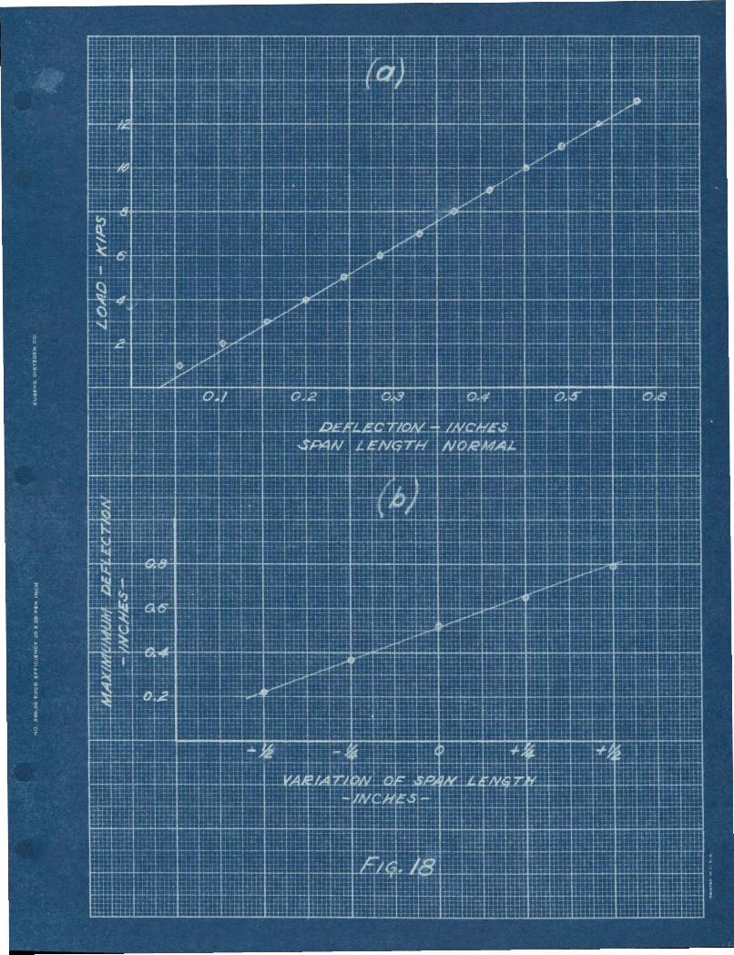
reaotion, a8 shoft graphioally ill (b) ot rig. 1'1, i8 as olose
as CaD be expeoted, ooDslclerlns the aoouracy ot the observation.
lOr purposes ot oomparlson, 'the oritioal stresses were
oalculated by seversl methods &S 110 ted in tho table.. The de~
'~lgn assumptions on whlcb the calculations ware based are: (1)
there Is a 11nea~ Ysrlatlon ot normal stress on the h~rlzontal
sec.tion through· the insi4e oornerot the knee and OD the ver
tioal section at midspan, (2) on ~he vertioal section through
the Inslcle corDer ot the bee. all tbe moment ed thrust i8
transferred through the tlanses. The add!tlonal set of values
tor the J:l8x!ltU11 stresses in the 8irder at the COrDer were eel
oUle,t&d OD t~e baale ot the conventional bea:Jl tol'muls.
The AlaxlaUJl compression values tor tbegirder at the
corner. ere all. hlgh aUG to the concentratioJl.ot stress previ
ously mentioned. However" the average stress 80ross t,he bottom
':"'"

-=- 13
tl8DS6 agreed olosely wltb the valuel oaloulated on 'he tlret
two a"~WDPtlol1so- Theoompresslon values III the oolwm are
also biBb, whloh-mal be partially due to the same ooncentra~
tlono '!he taot tbat the tension values 1rlthe oolWIIQ ue loy
Indicate. that ourved beam aot10l1 le alao IDvolvedo
The-obeerved maxl~UID '_n.l0D In tbe slrderst the cor
ner tal1a between the theoretloal values based on the two fun
damental assumptfoDSo The assumptloD ~bat the flaDges take
all of the moment eD4 th!!uat leads to the more oOJlse"atlve
de818n.
The asreement between the obi.ened del theoretical
values ot strese on the seetloD atmlds,paD 18 within the
lllll1ts ot exper1Jlental enorll
'is 0 l' aDd 18 deDlOnst;rate that the trame behaves·el....
88t108111 both In re.peot to the applloatlon ot load and to
the variation ot SPall length ..
A9ENDA'fhe~ve.tI8atlon Ie to be oontinue4 durlns t~•. ao8
dem10 ,ea~ ot 193'1-1938. I'Urtber tests on the square-knee
model will be run to 4eter.mlne the etteot ot various support. - ~ .
cOD~~tloDS, suoh 8e tull and partial tlxatlon. The results
.111·be compared with the ~esult8 already obtained with hinged
allpports.
/

... 14
A tull aet or teata w111 be.de on • oollplete mode!
of tbe curved-kDee~1Pe, whloh 1••~ilar ~o teat apeo1men
mo ~-. 2 ot the Bureau or Standard. pro Ject 0 'lb1a model hae
been fabricated ahd Ie ready to be t ••te4 aa IJOOI1 ., the 10:"
veetlgstion 18 resumed 111 t~e Pall of the current ,eare
,. ..... ,..-¢';:!I ..

TABLE I
- .iOBfES'l' SPEC~ NO .Ll -
-COuponNo.
COuponCut From
'J.'h1ok- YO~g"8 Yield TensIle Elongationness llodulU$ ot Point st:r~l.igth in 8 in.___ BlastlcltJ' ,-
tn. kips/ina kips per aq in per centZQi-........
Angle If· -Q.196 . 29,000
Angle T.. . .1'113' 28,500
1
I
3
4:
5
6
'1
8
9
AIlg1eB • • laS
Angle B·· ..192
Angle S·, .. 189
AD8l, S·· ,.1'0
_18 LL .15V
Pla'e aL .159
Plate M .162
28,400
29,400
28,300
a6,800
29,100
28,200
28,400
45.2 64.0
43.0 64.6
44.4 66.6
43.8 65.4
39.9 55 •.&
42.5 60.0
4'1.6 -56.'
••• 4 51.9
45.3 5••5
21.~
23.1
24.4
2'7.4-
24.8
22.2
22.0
AveraBe 28.600(
.. - - .. .. ...10
11
'fie Bar -1
Tie Sar2
28.600"
aO~500

',"'< ,
tb' '1'ABLE II
COUPARlOON or 'lIJPX)RETICAL AND OBSERVID ORITIOAL V~UES
j .
Variation ot Span-ln. +1/2 +1/4:.o . -1/4 -1/2
Maximum Tension In .t 19,900 1,6,350• ~.OOO 15,200Girder a1; II~A-apan 0.20,600 · 16, '100
Maximum Compression ~1~~,OOO 18,600. In Girde, . • 20,600 18,000
at M14~.pan 0 23,200 '19,400~ - '. . -
Horizontal (Ob'_tved .,590Thrv.st (Caloulated .,810
Maxtmum TeDslon '1 11.'00in Girder 12.~OOat .Corft.er • 12,350.... , 11,100
·f 19.~OOMaximum CompreaaloQ • 16,600in Girder at Corner • 16,000
. , 13,100
Maximum Compression 1 1',200. I' 1 • 13 500. n Co WIlD 0 13:100
- -
. "
"c,
6,9006,900~,900
9,60010,00010,000
12,00013, '10013, '100
28,20019,80019,8001~,000
5.8B05&890
14,80016,15016,15014,000
r
11,lOC)13,10013 ,'100
10,1009,'009,'100
21,600' 22,00016,400 16,00016,400 16,000
5,6008,SBO
14.1501&,40015,4001.3,,200
26,90019,00018,90015.200
15,500 . 12, '0015,300 12, 'laO16,300 12, 'laO
0,2'0~,360
13 40014': '100~4,350
,,12,500'
29,00018~2001'1,80014,500
20,50014.'10014,600
10,50012,50012,300
13,10012, tOo1~~400
.,9605,080
12,60013,90013,45011,900
26,8001',400·,16,90013,800
18,10014,10013;900
10,25011,90011,600
t 9,95011,200
o 10,eOO~ax1mUlll Tension
In C01\DDJl
f..Observed valueet'f' CalCUlated trom Theoretioal HorlzontalRe8ot,lon on Bases
of DeslgD Assumption&, .
o calculated trom Observed HOrizontal Reaction OD Basis otDesign Assumptions
, Oe.1cnlated t1'01Il Theoretio.al Horizontal Reaction on Basi.sot ~ullSectlon Aotlng . .
'!)'~ead1n8s adjusted beoause ot tau1ty instrument•.~'
/
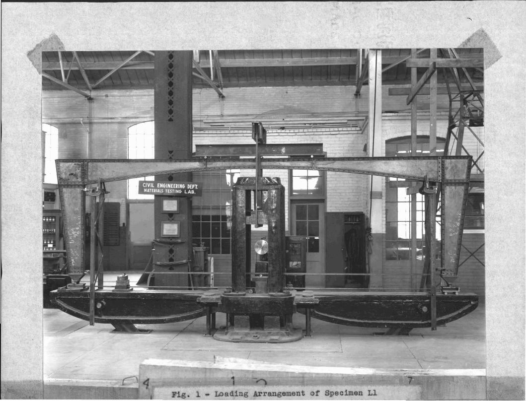
Fig. 1 - Loading Arrangement or Specimen Ll


Fig. 4 - Detai~s of Moveable Base of Frame Ll

Fig. 5 - Detail of Fixed Baae of Frame Ll