Embed Size (px)
Citation preview
Progress towards a high-gain and robust target design for heavy ion fusionEnrique Henestroza and B. Grant Logan Citation: Phys. Plasmas 19, 072706 (2012); doi: 10.1063/1.4737587 View online: http://dx.doi.org/10.1063/1.4737587 View Table of Contents: http://pop.aip.org/resource/1/PHPAEN/v19/i7 Published by the American Institute of Physics. Related ArticlesSolid debris collection for radiochemical diagnostics at the National Ignition Facility Rev. Sci. Instrum. 83, 10D904 (2012) Fast-electron self-collimation in a plasma density gradient Phys. Plasmas 19, 062702 (2012) Measurements of hohlraum-produced fast ions Phys. Plasmas 19, 042707 (2012) A polar-drive–ignition design for the National Ignition Facility Phys. Plasmas 19, 056308 (2012) Multiple spherically converging shock waves in liquid deuterium Phys. Plasmas 18, 092706 (2011) Additional information on Phys. PlasmasJournal Homepage: http://pop.aip.org/ Journal Information: http://pop.aip.org/about/about_the_journal Top downloads: http://pop.aip.org/features/most_downloaded Information for Authors: http://pop.aip.org/authors
Progress towards a high-gain and robust target design for heavy ion fusion
Enrique Henestroza and B. Grant LoganLawrence Berkeley National Laboratory, Berkeley, California 94720, USA
(Received 16 April 2012; accepted 11 June 2012; published online 19 July 2012)
Recently [E. Henestroza et al., Phys. Plasmas 18, 032702 (2011)], a new inertial-fusion target
configuration, the X-target, using one-sided axial illumination has been explored. This class of
target uses annular and solid-profile heavy ion beams to compress and ignite deuterium-tritium
(DT) fuel that fills the interior of metal cases that have side-view cross sections in the shape of an
“X.” X-targets using all-DT-filled metal cases imploded by three annular ion beams resulted in fuel
densities of �50 g/cm3 at peak compression, and fusion gains of �50, comparable to heavy ion
driven hohlraum targets [D. A. Callahan-Miller and M. Tabak, Phys. Plasmas 7, 2083 (2000)]. This
paper discusses updated X-target configurations that incorporate inside the case a propellant
(plastic) and a pusher (aluminum) surrounding the DT fuel. The updated configurations are capable
of assembling higher fuel areal densities �2 g/cm2 using two annular beams to implode the target
to peak DT densities �100 g/cm3, followed by a fast-ignition solid ion beam which heats the
high-density fuel to thermonuclear temperatures in �200 ps to start the burn propagation, obtaining
gains of �300. These targets have been modeled using the radiation-hydrodynamics code HYDRA
[M. M. Marinak et al., Phys. Plasmas 8, 2275 (2001)] in two- and three- dimensions to study the
properties of the implosion as well as the ignition and burn propagation phases. At typical Eulerian
mesh resolutions of a few microns, the aluminum-DT interface shows negligible Rayleigh–Taylor
(RT) and Richtmyer–Meshkov instability growth; also, the shear flow of the DT fuel as it slides
along the metal X-target walls, which drives the RT and Kelvin Helmholtz instabilities, does not
have a major effect on the burning rate. An analytic estimate of the RT instability process at the
Al-DT interface shows that the aluminum spikes generated during the pusher deceleration phase
would not reach the ignition zone in time to affect the burning process. Also, preliminary HYDRA
calculations, using a higher resolution mesh to study the shear flow of the DT fuel along the
X-target walls, indicate that metal-mixed fuel produced near the walls would not be transferred to
the DT ignition zone (at maximum qR) located at the vertex of the X-target. VC 2012 AmericanInstitute of Physics. [http://dx.doi.org/10.1063/1.4737587]
I. INTRODUCTION
In a previous paper,1 a new inertial-fusion target config-
uration, the X-target, using one-sided axial illumination has
been explored. This class of target uses annular and solid-
profile heavy ion beams to compress and ignite deuterium-
tritium (DT) fuel that fills the interior of metal cases that
have side-view cross sections in the shape of an “X.” The
HYDRA (Ref. 2) radiation-hydrodynamics code was used in
axisymmetric 2D to find target configurations to produce
quasi-spherical compression of the fuel toward the X-vertex
on axis by controlling the geometry of the case, and the suc-
cessive timing, power, and radii of nested annuli of ion
beams. As reported,1 X-targets consisting of all-DT-filled
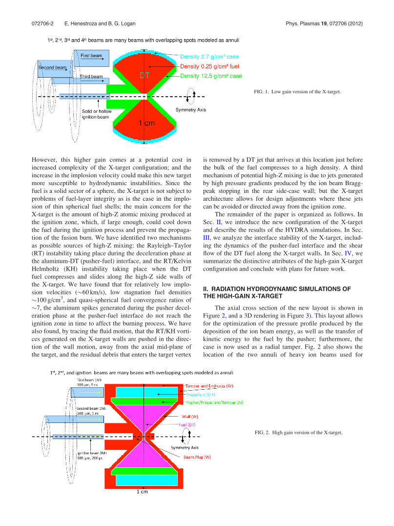
metal cases imploded by three annular ion beams (Fig. 1)
resulted in peak fuel densities of �50 g/cm3 at peak com-
pression, and fusion gains of �50, comparable to heavy ion
driven hohlraum targets.3
In this paper, we find much higher target gains of 300 in
X-target configurations by incorporating inside the case a pro-
pellant (plastic) and a pusher (aluminum) surrounding the DT
fuel. These configurations are capable of assembling higher
fuel areal densities �2 g/cm2 using two annular beams to
implode the target. As a result, only 2 MJ of compression
beam energy is required with two compression pulses, instead
of 3 MJ with three compression pulses as in the previous all-
DT version.1 Because of the higher fuel qR, much higher fuel
burnup fractions (0.2) and fusion yields (1.5 GJ) are obtained,
so that with 3 MJ of fast-ignition beam energy, we obtain
gains of �300. The inclusion of a propellant, and a pusher
which later in time becomes a higher-pressure propellant (as
an "exploding pusher”) improves implosion compression effi-
ciency. This is achieved by improving the coupling efficiency
of the ion beam energy, particularly from the second compres-
sion beam to the aluminum pusher, which can transfer more
of its kinetic energy to the fuel. Furthermore, the outer case
improves the first compression beam’s coupling by acting as a
radial tamper. The numerical simulations include hydro
effects of the beams penetrating and heating all the compo-
nents of the X-target. The metal case is important for tamping;
and expansion of the case can be tailored to improve the
quasi-spherical symmetry of the initial fuel compression. The
implosion phase of the X-target does not change appreciably
when radiation transport is turned off in the calculations; this
shows that radiation drive is unimportant to the fuel compres-
sion, compared to hydro pressure.
The six-fold increase in gain of the new X-target is
obtained via an increase by a factor of two in the implosion
velocity of the DT fuel, thus, producing a higher stagnation
density as well as a higher areal density at the ignition zone.
1070-664X/2012/19(7)/072706/7/$30.00 VC 2012 American Institute of Physics19, 072706-1
PHYSICS OF PLASMAS 19, 072706 (2012)
However, this higher gain comes at a potential cost in
increased complexity of the X-target configuration; and the
increase in the implosion velocity could make this new target
more susceptible to hydrodynamic instabilities. Since the
fuel is a solid sector of a sphere, the X-target is not subject to
problems of fuel-layer integrity as is the case in the implo-
sion of thin spherical fuel shells; the main concern for the
X-target is the amount of high-Z atomic mixing produced at
the ignition zone, which, if large enough, could cool down
the fuel during the ignition process and prevent the propaga-
tion of the fusion burn. We have identified two mechanisms
as possible sources of high-Z mixing: the Rayleigh–Taylor
(RT) instability taking place during the deceleration phase at
the aluminum-DT (pusher-fuel) interface, and the RT/Kelvin
Helmholtz (KH) instability taking place when the DT
fuel compresses and slides along the high-Z side walls of
the X-target. We have found that for relatively low implo-
sion velocities (�60 km/s), low stagnation fuel densities
�100 g/cm3, and quasi-spherical fuel convergence ratios of
�7, the aluminum spikes generated during the pusher decel-
eration phase at the pusher-fuel interface do not reach the
ignition zone in time to affect the burning process. We have
also found, by tracing the fluid motion, that the RT/KH vorti-
ces generated on the X-target walls are pushed in the direc-
tion of the wall motion, away from the axial mid-plane of
the target, and the residual debris that enters the target vertex
is removed by a DT jet that arrives at this location just before
the bulk of the fuel compresses to a high density. A third
mechanism of potential high-Z mixing is due to jets generated
by high pressure gradients produced by the ion beam Bragg-
peak stopping in the rear side-case wall; but the X-target
architecture allows for design adjustments where these jets
can be avoided or directed away from the ignition zone.
The remainder of the paper is organized as follows. In
Sec. II, we introduce the new configuration of the X-target
and describe the results of the HYDRA simulations. In Sec.
III, we analyze the interface stability of the X-target, includ-
ing the dynamics of the pusher-fuel interface and the shear
flow of the DT fuel along the X-target walls. In Sec. IV, we
summarize the distinctive attributes of the high-gain X-target
configuration and conclude with plans for future work.
II. RADIATION HYDRODYNAMIC SIMULATIONS OFTHE HIGH-GAIN X-TARGET
The axial cross section of the new layout is shown in
Figure 2, and a 3D rendering in Figure 3). This layout allows
for the optimization of the pressure profile produced by the
deposition of the ion beam energy, as well as the transfer of
kinetic energy to the fuel by the pusher; furthermore, the
case is now used as a radial tamper. Fig. 2 also shows the
location of the two annuli of heavy ion beams used for
FIG. 1. Low gain version of the X-target.
FIG. 2. High gain version of the X-target.
072706-2 E. Henestroza and B. G. Logan Phys. Plasmas 19, 072706 (2012)
compression, as well as the solid central beam used for igni-
tion. The implosion requires two 1 MJ ion beam annuli; the
pulse lengths are 5-ns and 1-ns Gaussian FWHM, with the
second implosion beam injected �120 ns after the first; the
width of both annuli are 500 lm Gaussian FWHM. The igni-
tion beam is a 3 MJ solid ion beam of 100 ps Gaussian
FWHM pulse length (total width of 400 ps), injected at the
time of maximum compression (�136 ns); the beam size is
300 lm Gaussian FWHM. The overall dimension of the tar-
get is 1 cm in diameter.
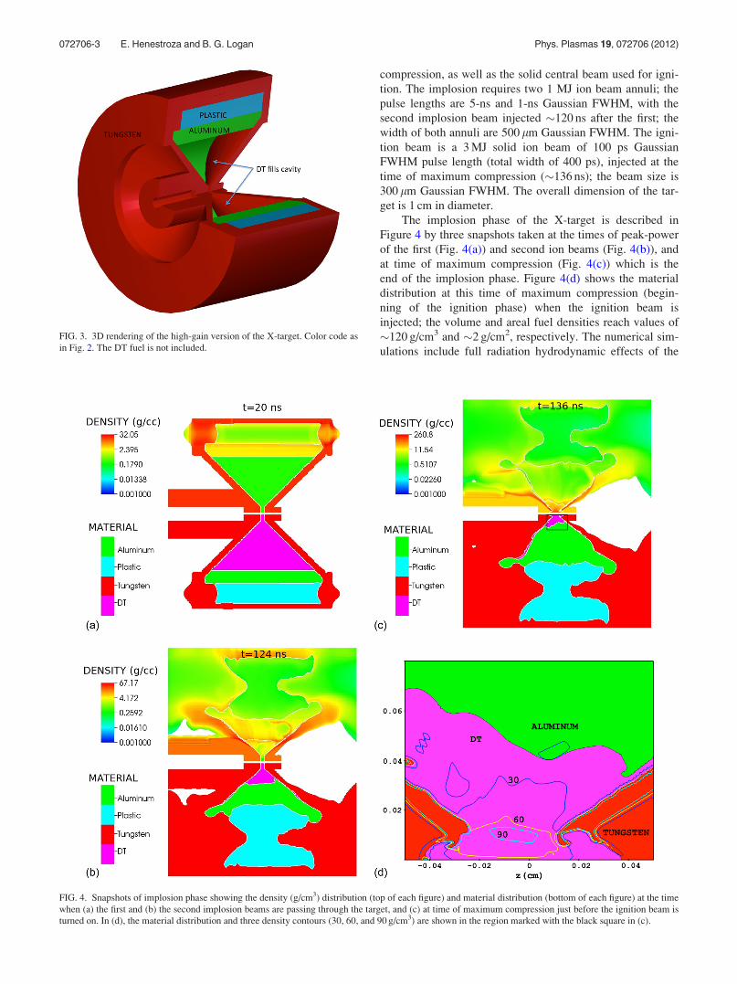
The implosion phase of the X-target is described in
Figure 4 by three snapshots taken at the times of peak-power
of the first (Fig. 4(a)) and second ion beams (Fig. 4(b)), and
at time of maximum compression (Fig. 4(c)) which is the
end of the implosion phase. Figure 4(d) shows the material
distribution at this time of maximum compression (begin-
ning of the ignition phase) when the ignition beam is
injected; the volume and areal fuel densities reach values of
�120 g/cm3 and �2 g/cm2, respectively. The numerical sim-
ulations include full radiation hydrodynamic effects of the
FIG. 3. 3D rendering of the high-gain version of the X-target. Color code as
in Fig. 2. The DT fuel is not included.
FIG. 4. Snapshots of implosion phase showing the density (g/cm3) distribution (top of each figure) and material distribution (bottom of each figure) at the time
when (a) the first and (b) the second implosion beams are passing through the target, and (c) at time of maximum compression just before the ignition beam is
turned on. In (d), the material distribution and three density contours (30, 60, and 90 g/cm3) are shown in the region marked with the black square in (c).
072706-3 E. Henestroza and B. G. Logan Phys. Plasmas 19, 072706 (2012)
beams penetrating and heating all the components of the
X-target, assuming axisymmetric target and annular and
solid beams.
The ion-beam energy deposition is calculated in
HYDRA by tracing the ion beam along a rectilinear trajec-
tory and computing the absorbed energy in each mesh cell
using a classical formula for energy loss in partially ionized
plasmas. This generalized Bethe formula4 includes contribu-
tions for both bound and free electrons, and uses the Betz
formula for the effective charge state of the ion.
The HYDRA calculations also show that the implosion
(and ignition) dynamics is minimally affected by a change of
the ion species as long as the ranges are the same; thus, we
could use, e.g., 20 GeV rubidium or 90 GeV uranium ion
beams.
The implosion dynamics is modified by 3D effects pro-
duced by the fact that the annular beams may be composed
of individual solid beams located in a ring pattern, which
breaks the assumption of rotational symmetry; these effects
were studied for the case of a periodic layout of 20 beams
along the azimuth; the 3D simulation was performed taking
an 18� wedge of the X-target containing a single round solid
beam and applying periodic boundary conditions. The results
show a small effect on the final densities, effects that may be
minimized by a further optimization of the beam parameters.
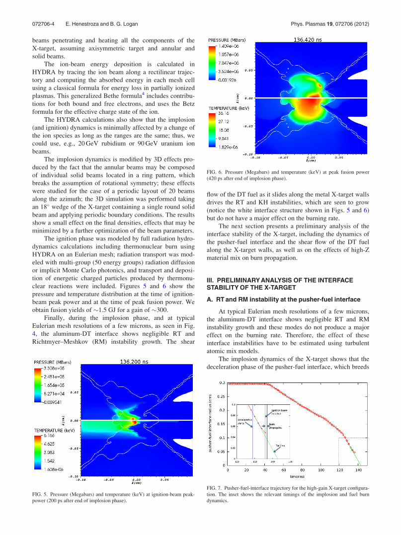
The ignition phase was modeled by full radiation hydro-
dynamics calculations including thermonuclear burn using
HYDRA on an Eulerian mesh; radiation transport was mod-
eled with multi-group (50 energy groups) radiation diffusion
or implicit Monte Carlo photonics, and transport and deposi-
tion of energetic charged particles produced by thermonu-
clear reactions were included. Figures 5 and 6 show the
pressure and temperature distribution at the time of ignition-
beam peak power and at the time of peak fusion power. We
obtain fusion yields of �1.5 GJ for a gain of �300.
Finally, during the implosion phase, and at typical
Eulerian mesh resolutions of a few microns, as seen in Fig.
4, the aluminum-DT interface shows negligible RT and
Richtmyer–Meshkov (RM) instability growth. The shear
flow of the DT fuel as it slides along the metal X-target walls
drives the RT and KH instabilities, which are seen to grow
(notice the white interface structure shown in Figs. 5 and 6)
but do not have a major effect on the burning rate.
The next section presents a preliminary analysis of the
interface stability of the X-target, including the dynamics of
the pusher-fuel interface and the shear flow of the DT fuel
along the X-target walls, as well as on the effects of high-Z
material mix on burn propagation.
III. PRELIMINARY ANALYSIS OF THE INTERFACESTABILITY OF THE X-TARGET
A. RT and RM instability at the pusher-fuel interface
At typical Eulerian mesh resolutions of a few microns,
the aluminum-DT interface shows negligible RT and RM
instability growth and these modes do not produce a major
effect on the burning rate. Therefore, the effect of these
interface instabilities have to be estimated using turbulent
atomic mix models.
The implosion dynamics of the X-target shows that the
deceleration phase of the pusher-fuel interface, which breeds
FIG. 5. Pressure (Megabars) and temperature (keV) at ignition-beam peak-
power (200 ps after end of implosion phase).
FIG. 6. Pressure (Megabars) and temperature (keV) at peak fusion power
(420 ps after end of implosion phase).
FIG. 7. Pusher-fuel-interface trajectory for the high-gain X-target configura-
tion. The inset shows the relevant timings of the implosion and fuel burn
dynamics.
072706-4 E. Henestroza and B. G. Logan Phys. Plasmas 19, 072706 (2012)
the RT instability, starts at 129 ns and lasts for 7 ns, at which
time the ignition beam is injected. The average interface
deceleration is a� 4.3� 1014 cm/s2 at a radius of 0.0840 cm,
with the speed decreasing from v� 6� 106 cm/s to
3� 106 cm/s, which translates into a free-fall time of 14 ns.
As shown in Fig. 7, the spikes generated by the RT instabil-
ity would not reach the ignition region (r� 0.0250 cm) even
if they were to follow the “fall line.”
The following analytic estimates of RT/RM instability
growth follow closely the analysis described in the book of
Atzeni and Meyer-ter-Vehn.5
The growth rates and e-folding times can be estimated
from the classical formulas. The Atwood number is found to
be almost constant and equal to 0.2 during that interval;
therefore, the classic e-folding time in seconds for perturba-
tions of wavenumber k is �1� 10�7/Hk with k in cm�1.
Thus, for perturbations of (spherical) mode number ‘¼ 36 at
R¼ 0.06 cm, we have k¼ 600 cm�1, which produces an
e-folding time of �4 ns. For perturbations of mode number
‘¼ 216, we have k¼ 3600 cm�1, which produces an
e-folding time of �1.7 ns. These estimates shows that only
high order modes >36 could grow enough to perturb the dy-
namics at the ignition zone
We can also estimate the penetration depth of the insta-
bility arising from random perturbations. The time evolution
of the width of the turbulent mixing layer due to RT/RM
instability can be qualitatively described by dimensional
arguments.5 The width of the mixing layer at the interface is
proportional to A*a*t2, where A is the Atwood number, a is
the interface acceleration, and t is the time during which the
instability persist; the factor of proportionality is around
4%–7% as obtained from fits to experimental results. From
the values already provided, we estimate a penetration depth
of 5 lm.
Therefore, this RT/RM instability analysis at the pusher-
fuel interface estimates that the aluminum spikes generated
during the pusher deceleration phase would not reach the igni-
tion zone in time to affect the burning process. However,
more work is needed with higher resolution over the entire
X-target, to be sure no aluminum metal jets (sometimes
observed near the ignition zone) are created by beam Bragg
peaks hitting the walls in the outer case. Our analysis, while
encouraging, needs to be confirmed by experiments.
In a personal communication in Ref. 10, we were
informed that a k-L turbulence model6 calculation of an
equivalent X-target design shows that the pusher-fuel inter-
face does not generate enough high-Z mix to affect the igni-
tion process.
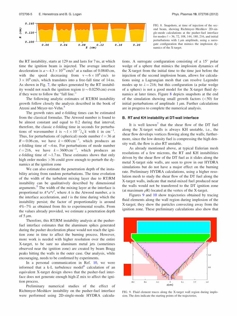
Preliminary numerical studies of the effect of
Richtmyer-Meshkov instability on the pusher-fuel interface
were performed using 2D-single-mode HYDRA calcula-
tions. A surrogate configuration consisting of a 15� polar
wedge of a sphere that mimics the implosion dynamics of
the X-target from the initial time to the time just before the
injection of the second implosion beam, allows for calcula-
tions using a Lagrangian mesh that can resolve Legendre
modes up to k¼ 216; but this configuration (a polar wedge
of a sphere) is not a good model for the X-target fluid dy-
namics at later times. Figure 8 depicts snapshots at the end
of the simulation showing small growth factors (<50) for
initial perturbations of amplitude 1 lm. Further calculations
are in progress to complete the numerical analysis.
B. RT and KH instability at DT-wall interface
It is well known7 that the shear flow of the DT fuel
along the X-target walls is always KH unstable, i.e., the
shear flow develops vortices flowing along the walls; further-
more, since the low density fuel is compressing the high den-
sity wall, the flow is also RT unstable.
As already mentioned above, at typical Eulerian mesh
resolutions of a few microns, the RT and KH instabilities
driven by the shear flow of the DT fuel as it slides along the
metal X-target side walls, are seen to grow in our HYDRA
simulations but do not have a major effect on the burning
rate. Preliminary HYDRA calculations, using a higher reso-
lution mesh to study the shear flow of the DT fuel along the
X-target walls, indicate that metal-mixed fuel produced near
the walls would not be transferred to the DT ignition zone
(at maximum qR) located at the vertex of the X-target.
Figures 9 and 10 show trajectories obtained by tracing
fluid elements along the wall region during implosion of the
X-target; they show the particles convecting away from the
ignition zone. These preliminary calculations also show that
FIG. 8. Snapshots, at time of injection of the sec-
ond beam, showing Richtmyer–Meshkov 2D-sin-
gle-mode calculations at the pusher-fuel interface
for modes ‘¼ 36, 72, 108, 144, 180, 216, and initial
perturbations with 1 lm amplitude, using a surro-
gate configuration that mimics the implosion dy-
namics of the X-target.
FIG. 9. Fluid element traces along the X-target wall region during implo-
sion. The dots indicate the starting points of the trajectories.
072706-5 E. Henestroza and B. G. Logan Phys. Plasmas 19, 072706 (2012)
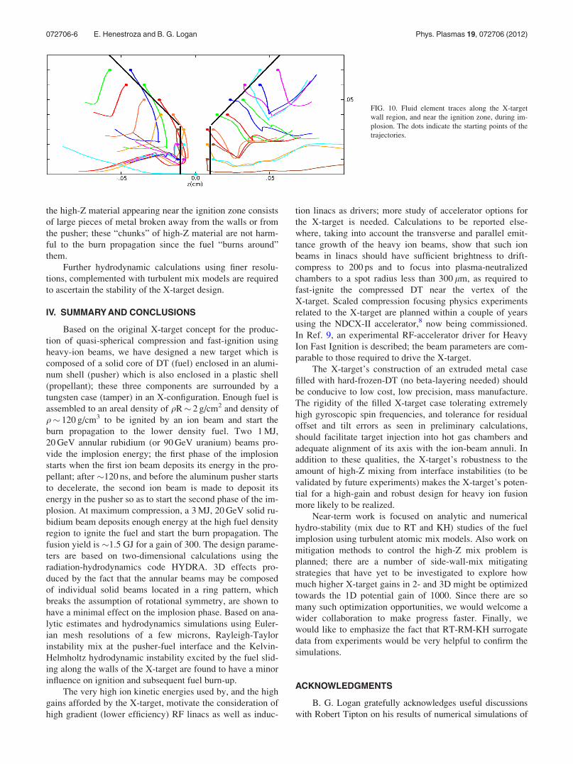
the high-Z material appearing near the ignition zone consists
of large pieces of metal broken away from the walls or from
the pusher; these “chunks” of high-Z material are not harm-
ful to the burn propagation since the fuel “burns around”
them.
Further hydrodynamic calculations using finer resolu-
tions, complemented with turbulent mix models are required
to ascertain the stability of the X-target design.
IV. SUMMARY AND CONCLUSIONS
Based on the original X-target concept for the produc-
tion of quasi-spherical compression and fast-ignition using
heavy-ion beams, we have designed a new target which is
composed of a solid core of DT (fuel) enclosed in an alumi-
num shell (pusher) which is also enclosed in a plastic shell
(propellant); these three components are surrounded by a
tungsten case (tamper) in an X-configuration. Enough fuel is
assembled to an areal density of qR� 2 g/cm2 and density of
q� 120 g/cm3 to be ignited by an ion beam and start the
burn propagation to the lower density fuel. Two 1 MJ,
20 GeV annular rubidium (or 90 GeV uranium) beams pro-
vide the implosion energy; the first phase of the implosion
starts when the first ion beam deposits its energy in the pro-
pellant; after �120 ns, and before the aluminum pusher starts
to decelerate, the second ion beam is made to deposit its
energy in the pusher so as to start the second phase of the im-
plosion. At maximum compression, a 3 MJ, 20 GeV solid ru-
bidium beam deposits enough energy at the high fuel density
region to ignite the fuel and start the burn propagation. The
fusion yield is �1.5 GJ for a gain of 300. The design parame-
ters are based on two-dimensional calculations using the
radiation-hydrodynamics code HYDRA. 3D effects pro-
duced by the fact that the annular beams may be composed
of individual solid beams located in a ring pattern, which
breaks the assumption of rotational symmetry, are shown to
have a minimal effect on the implosion phase. Based on ana-
lytic estimates and hydrodynamics simulations using Euler-
ian mesh resolutions of a few microns, Rayleigh-Taylor
instability mix at the pusher-fuel interface and the Kelvin-
Helmholtz hydrodynamic instability excited by the fuel slid-
ing along the walls of the X-target are found to have a minor
influence on ignition and subsequent fuel burn-up.
The very high ion kinetic energies used by, and the high
gains afforded by the X-target, motivate the consideration of
high gradient (lower efficiency) RF linacs as well as induc-
tion linacs as drivers; more study of accelerator options for
the X-target is needed. Calculations to be reported else-
where, taking into account the transverse and parallel emit-
tance growth of the heavy ion beams, show that such ion
beams in linacs should have sufficient brightness to drift-
compress to 200 ps and to focus into plasma-neutralized
chambers to a spot radius less than 300 lm, as required to
fast-ignite the compressed DT near the vertex of the
X-target. Scaled compression focusing physics experiments
related to the X-target are planned within a couple of years
using the NDCX-II accelerator,8 now being commissioned.
In Ref. 9, an experimental RF-accelerator driver for Heavy
Ion Fast Ignition is described; the beam parameters are com-
parable to those required to drive the X-target.
The X-target’s construction of an extruded metal case
filled with hard-frozen-DT (no beta-layering needed) should
be conducive to low cost, low precision, mass manufacture.
The rigidity of the filled X-target case tolerating extremely
high gyroscopic spin frequencies, and tolerance for residual
offset and tilt errors as seen in preliminary calculations,
should facilitate target injection into hot gas chambers and
adequate alignment of its axis with the ion-beam annuli. In
addition to these qualities, the X-target’s robustness to the
amount of high-Z mixing from interface instabilities (to be
validated by future experiments) makes the X-target’s poten-
tial for a high-gain and robust design for heavy ion fusion
more likely to be realized.
Near-term work is focused on analytic and numerical
hydro-stability (mix due to RT and KH) studies of the fuel
implosion using turbulent atomic mix models. Also work on
mitigation methods to control the high-Z mix problem is
planned; there are a number of side-wall-mix mitigating
strategies that have yet to be investigated to explore how
much higher X-target gains in 2- and 3D might be optimized
towards the 1D potential gain of 1000. Since there are so
many such optimization opportunities, we would welcome a
wider collaboration to make progress faster. Finally, we
would like to emphasize the fact that RT-RM-KH surrogate
data from experiments would be very helpful to confirm the
simulations.
ACKNOWLEDGMENTS
B. G. Logan gratefully acknowledges useful discussions
with Robert Tipton on his results of numerical simulations of
FIG. 10. Fluid element traces along the X-target
wall region, and near the ignition zone, during im-
plosion. The dots indicate the starting points of the
trajectories.
072706-6 E. Henestroza and B. G. Logan Phys. Plasmas 19, 072706 (2012)

the X-target. We are very grateful to the anonymous reviewer
for comments that improved the quality of this manuscript.
This work was performed under the support of the U.S.
Department of Energy by the Lawrence Berkeley National
Laboratory under Contract No. DE-AC02-05CH11231.
1E. Henestroza, B. G. Logan, and L. J. Perkins, Phys. Plasmas 18, 032702
(2011).2M. M. Marinak, G. D. Kerbel, N. A. Gentile, O. Jones, D. Munro, S. Pol-
laine, T. R. Dittrich, and S. W. Haan, Phys. Plasmas 8, 2275 (2001).3D. A. Callahan-Miller and M. Tabak, Phys. Plasmas 7, 2083 (2000).4B. G. Logan, L. J. Perkins, and J. J. Barnard, Phys. Plasmas 15, 072701 (2008).
5S. Atzeni and J. Meyer-ter-Vehn, The Physics of Inertial Fusion,
International Series of Monographs on Physics No. 125 (Oxford Science,
2004).6G. Dimonte and R. Tipton, Phys. Fluids 18, 085101 (2006).7S. Chandrasekhar, Hydrodynamics and Hydromagnetic Stability (Dover,
New York, 1981).8A. Friedman, J. J. Barnard, R. H. Cohen, D. P. Grote, S. M. Lund, W. M.
Sharp, A. Faltens, E. Henestroza, J.-Y. Jung, J. W. Kwan, E. P. Lee, M. A.
Leitner, B. G. Logan, J.-L. Vay, W. L. Waldron, R. C. Davidson, M. Dorf,
E. P. Gilson, and I. D. Kaganovich, Phys. Plasmas 17, 056704 (2010).9B. Y. Sharkov, N. N. Alexeev, M. M. Basko, M. D. Churazov, D. G. Kosh-
karev, S. A. Medin, Y. N. Orlov, and V. M. Suslin, Nucl. Fusion 45, S291
(2005).10R. Tipton, personal communication (August 2011).
072706-7 E. Henestroza and B. G. Logan Phys. Plasmas 19, 072706 (2012)


![Robust Gain-Scheduled PID Control: A Parameter Dependent ... · interpolation or switching of the PID gains produces a gain-scheduling [3]. The GS PID has been proven to be effective](https://img.pdfslide.net/doc/110x75/5f0859137e708231d4219052/robust-gain-scheduled-pid-control-a-parameter-dependent-interpolation-or-switching.jpg)