Embed Size (px)
Citation preview
Progress towards Multi-Criteria Design Optimisation using DesignScript with SMART Form, Robot Structural analysis and
Ecotect building performance analysis
Robert Aish, Autodesk, Al Fisher, Buro Happold,
Sam Joyce, University of Bath, Andrew Marsh, Autodesk
Abstract
Important progress towards the development of a system that enables multi-criteria design
optimisation has recently been demonstrated during a research collaboration between
Autodesk‟s DesignScript development team, the University of Bath and the engineering
consultancy Buro Happold. This involved integrating aspects of the Robot Structural
Analysis application, aspects of the Ecotect building performance application and a
specialist form finding solver called SMART Form (developed by Buro Happold) with
DesignScript to create a single computation environment. This environment is intended for
the generation and evaluation of building designs against both structural and building
performance criteria, with the aim of expediently supporting computational optimisation
and decision making processes that integrate across multiple design and engineering
disciplines.
A framework was developed to enable the integration of modeling environments with
analysis and process control, based on the authors‟ case studies and experience of applied
performance driven design in practice. This more generalised approach (implemented in
DesignScript) enables different designers and engineers to selectively configure geometry
definition, form finding, analysis and simulation tools in an open-ended system without
enforcing any predefined workflows or anticipating specific design strategies and allows
for a full range of optimisation and decision making processes to be explored.
This system has been demonstrated to practitioners during the Design Modeling
Symposium, Berlin in 2011 and feedback from this has suggested further development.
1 Introduction
The optimum design of buildings is a recurring challenge to architecture and engineering
teams. But to begin with we need to define what we mean by design optimisation? „Design
Optimisation‟ is a really a shorthand for „performance satisficing‟, that is the design of
buildings to effectively satisfy multiple potentially conflicting performance criteria.
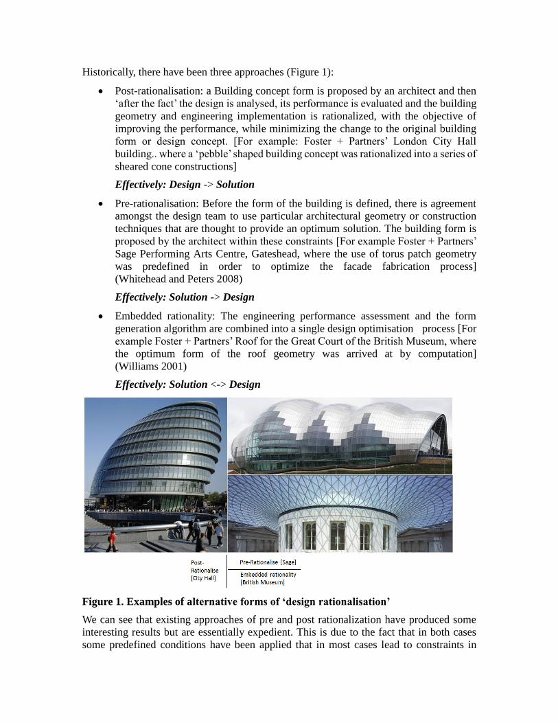
Historically, there have been three approaches (Figure 1):
Post-rationalisation: a Building concept form is proposed by an architect and then
„after the fact‟ the design is analysed, its performance is evaluated and the building
geometry and engineering implementation is rationalized, with the objective of
improving the performance, while minimizing the change to the original building
form or design concept. [For example: Foster + Partners‟ London City Hall
building.. where a „pebble‟ shaped building concept was rationalized into a series of
sheared cone constructions]
Effectively: Design -> Solution
Pre-rationalisation: Before the form of the building is defined, there is agreement
amongst the design team to use particular architectural geometry or construction
techniques that are thought to provide an optimum solution. The building form is
proposed by the architect within these constraints [For example Foster + Partners‟
Sage Performing Arts Centre, Gateshead, where the use of torus patch geometry
was predefined in order to optimize the facade fabrication process]
(Whitehead and Peters 2008)
Effectively: Solution -> Design
Embedded rationality: The engineering performance assessment and the form
generation algorithm are combined into a single design optimisation process [For
example Foster + Partners‟ Roof for the Great Court of the British Museum, where
the optimum form of the roof geometry was arrived at by computation]
(Williams 2001)
Effectively: Solution <-> Design
Figure 1. Examples of alternative forms of ‘design rationalisation’
We can see that existing approaches of pre and post rationalization have produced some
interesting results but are essentially expedient. This is due to the fact that in both cases
some predefined conditions have been applied that in most cases lead to constraints in
deriving the optimal form. As such, it is generally accepted that the most appropriate
approach to truly open ended design optimisation is through embedded rationality.
This acceptance comes from the understanding that buildings are collections of closely
coupled subsystems, such as the envelop, internal spatial topology, structure, building
services, occupancies and energy transfer systems, each with their own engineering
discipline and performance criteria. To create an optimal building, there are important
interactions to be considered and trade-off‟s to be made within and between these
subsystems and the derived or emergent whole. Each subsystem may be evaluated in terms
of its capital and running costs. Therefore single criteria optimisation is inappropriate.
There are also practical issues for designers to gain access to design optimisation tools. A
„design-centric‟ approach is based on augmenting generative design tools with easy to use
analysis and optimisation add-on‟s, but the downside is that these add-on‟s often reflect the
assumptions of the add-on creator and may be restricted by these assumptions, while at the
same time such generality may not be matched to the specific design problem being
tackled.
Conversely specialised software tools, created by advanced scripting, can be used to
connect programs and control complex optimisation with decision making processes: the
downside of such specialist (or project specific) tools are that they are often: (a) only
applicable for use on well-defined problems in complex large scale projects (b) are not
sufficiently general or reusable (c) require considerable insight on the part of the users and
(d) are therefore not practical for the use by non-experts.
We can chart the evolution from conventional computer aided design to design
optimisation, as follows:
1. CAD ... early CAD tools were developed to offer a digital implementation of
conventional analogue design media, such as.. sketching, drafting, modeling,
which required the designer to „manually‟ construct the design configuration.
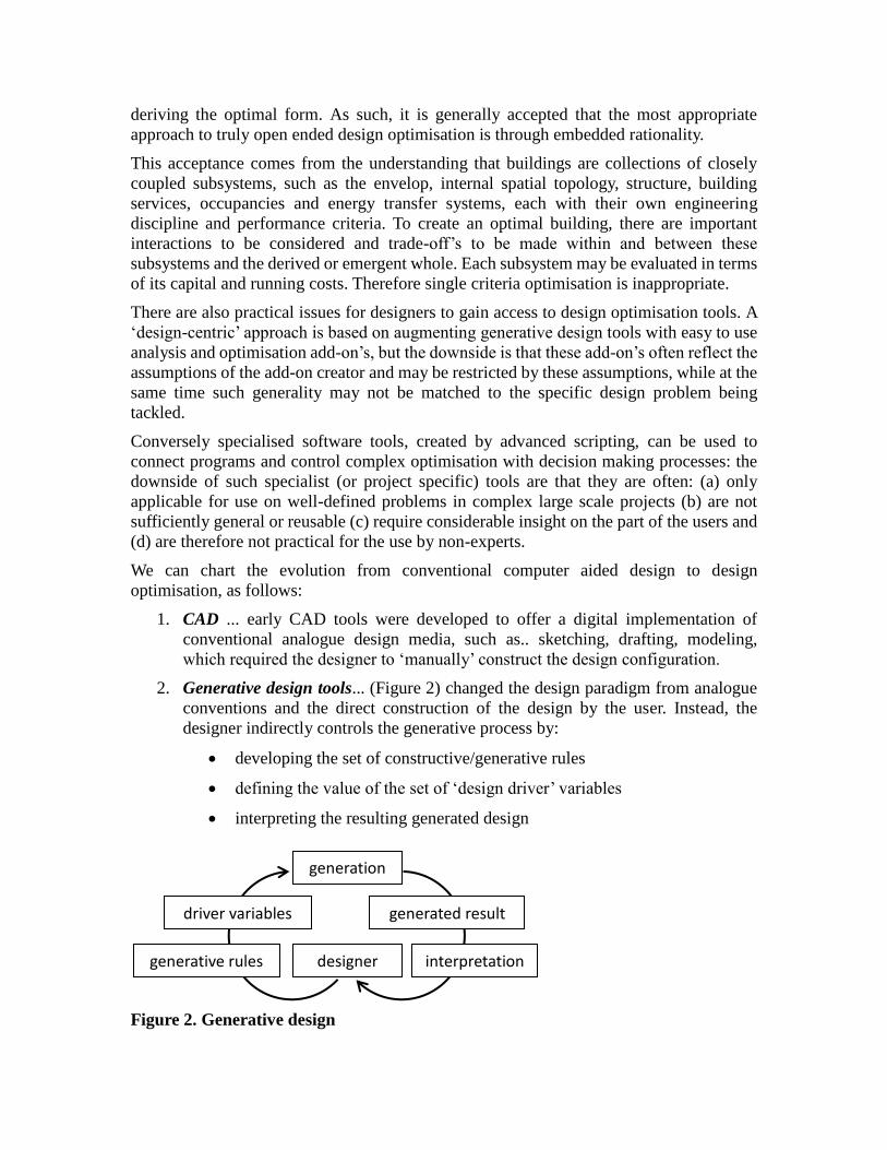
2. Generative design tools... (Figure 2) changed the design paradigm from analogue
conventions and the direct construction of the design by the user. Instead, the
designer indirectly controls the generative process by:
developing the set of constructive/generative rules
defining the value of the set of „design driver‟ variables
interpreting the resulting generated design
Figure 2. Generative design
generation
designer
generated result
interpretation
generative rules
driver variables
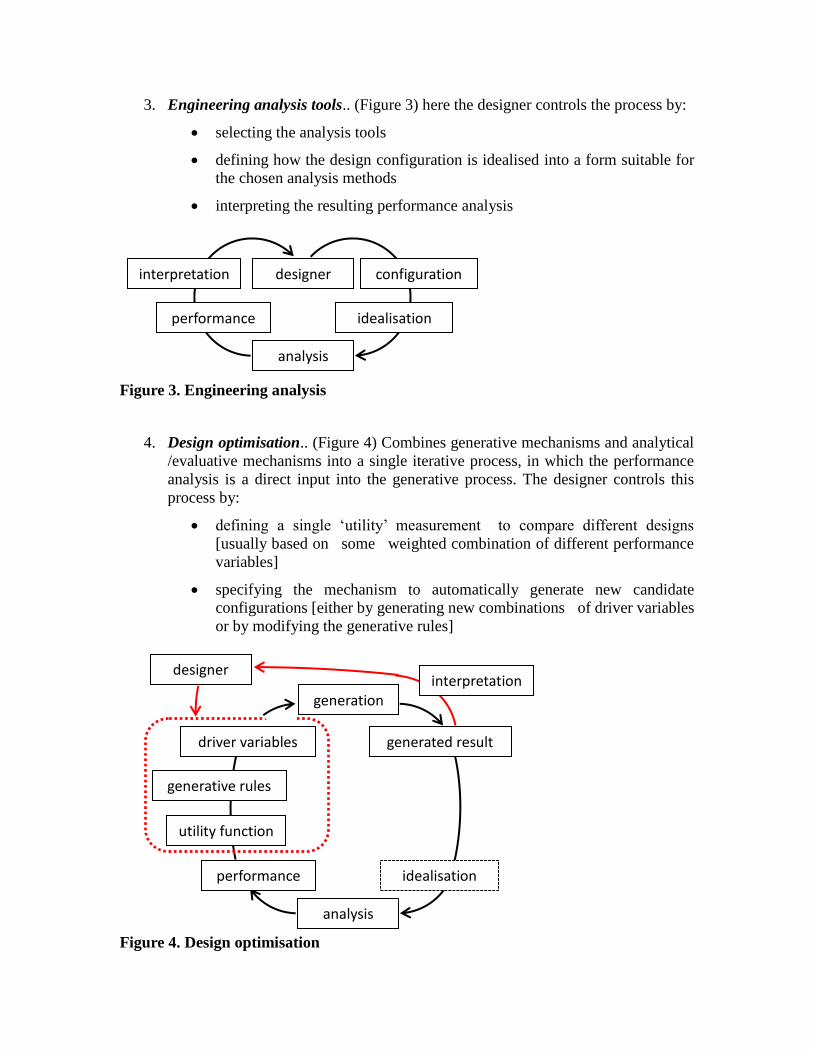
3. Engineering analysis tools.. (Figure 3) here the designer controls the process by:
selecting the analysis tools
defining how the design configuration is idealised into a form suitable for
the chosen analysis methods
interpreting the resulting performance analysis
Figure 3. Engineering analysis
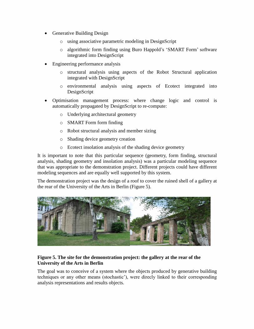
4. Design optimisation.. (Figure 4) Combines generative mechanisms and analytical
/evaluative mechanisms into a single iterative process, in which the performance
analysis is a direct input into the generative process. The designer controls this
process by:
defining a single „utility‟ measurement to compare different designs
[usually based on some weighted combination of different performance
variables]
specifying the mechanism to automatically generate new candidate
configurations [either by generating new combinations of driver variables
or by modifying the generative rules]
Figure 4. Design optimisation
designer
analysis
idealisation
configuration
interpretation
performance
generation
designer
generated result
generative rules
driver variables
analysis
idealisation
performance
utility function
interpretation
In the progression from CAD to Design Optimisation, we see increasing levels of
indirection as the designer progressively removes himself not just from the direct act of
designing, but also from the evaluative loop. He moves from „doing‟ to the far more
strategic role of „controlling‟.
So in summary, design optimisation depends on some or all of the following:
A generative process (to construct the design alternatives), which may be explicitly
driven by identifiable design variables
A number of evaluative processes (to evaluate the performance of the different
subsystems)
A fitness function to combine all performance criteria into a single fitness measure
A manager process that:
o initiates the generative process with some initial values for the design
variables
o drives the evaluative processes
o executes the fitness function
o decide whether an optimum design has been produced and if not
o refines the values of the design variables
o and continues the iterative optimisation process
Any one of these processes may use a human designer or engineer, or a computer based
application. The manager process may include numeric optimisation techniques, genetic
algorithms or neural networks for decision support. Also this process is in many instances
a hierarchy of systems and subsystems, each with their own internal decision making and
change propagation logic.
2 Current Research:
Progress towards the development of a multi-criteria design optimisation system has
recently been demonstrated during a joint research collaboration between the Autodesk‟s
DesignScript development team and the engineering consultancy Buro Happold. This
research builds on the authors‟ previous work, including the development of domain
specific end-user programming languages, (Aish, 2011), the use of genetic algorithms for
structural optimisation (Evins, Joyce et al, 2012) (Shrubshall and Fisher, 2011) and the
use of a physics solver to optimize geometric configuration of facade planar quads (Attar,
Aish, Stam et al 2009).
This project aimed to build on this research by integrating the following technologies
chosen for their broad but practically applicability informed by the authors experience in
the industry.
Generative Building Design
o using associative parametric modeling in DesignScript
o algorithmic form finding using Buro Happold‟s „SMART Form‟ software
integrated into DesignScript
Engineering performance analysis
o structural analysis using aspects of the Robot Structural application
integrated with DesignScript
o environmental analysis using aspects of Ecotect integrated into
DesignScript
Optimisation management process: where change logic and control is
automatically propagated by DesignScript to re-compute:
o Underlying architectural geometry
o SMART Form form finding
o Robot structural analysis and member sizing
o Shading device geometry creation
o Ecotect insolation analysis of the shading device geometry
It is important to note that this particular sequence (geometry, form finding, structural
analysis, shading geometry and insolation analysis) was a particular modeling sequence
that was appropriate to the demonstration project. Different projects could have different
modeling sequences and are equally well supported by this system.
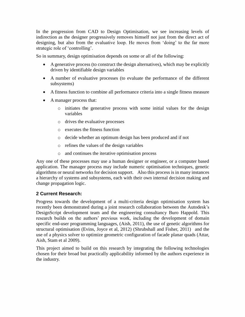
The demonstration project was the design of a roof to cover the ruined shell of a gallery at
the rear of the University of the Arts in Berlin (Figure 5).
Figure 5. The site for the demonstration project: the gallery at the rear of the
University of the Arts in Berlin
The goal was to conceive of a system where the objects produced by generative building
techniques or any other means (stochastic‟), were direcly linked to their corresponding
analysis representations and results objects.
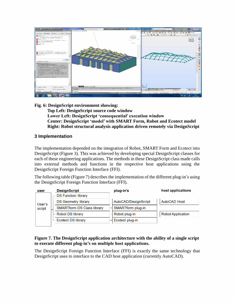
Fig. 6: DesignScript environment showing:
. Top Left: DesignScript source code window
. Lower Left: DesignScript ‘consequential’ execution window
. Center: DesignScript ‘model’ with SMART Form, Robot and Ecotect model
. Right: Robot structural analysis application driven remotely via DesignScript
3 Implementation
The implementation depended on the integration of Robot, SMART Form and Ecotect into
DesignScript (Figure 3). This was achieved by developing special DesignScript classes for
each of these engineering applications. The methods in these DesignScript class made calls
into external methods and functions in the respective host applications using the
DesignScript Foreign Function Interface (FFI).
The following table (Figure 7) describes the implementation of the different plug-in‟s using
the DesignScript Foreign Function Interface (FFI).
Figure 7. The DesignScript application architecture with the ability of a single script
to execute different plug-in’s on multiple host applications.
The DesignScript Foreign Function Interface (FFI) is exactly the same technology that
DesignScript uses to interface to the CAD host application (currently AutoCAD).

3.1 Robot integration
Implementation
The integration with the Robot structural analysis application was implemented as a series
of “Structural” classes directly accessible and instantiated by users. The connectivity of the
instances of these “Structural” classes builds graph-network relationships, with helper
functions to enable „dumb‟ geometry to be promoted to structural elements.
The elements of the structure to be calculated are then passed into an “Analysis” object.
The intention is that this “Analysis” object allows the user more direct control over the
execution of what could possibly be a computationally heavy task. This structural
“Analysis” object then creates a collection of structural “Result” objects corresponding to
the collection of input structural objects. In this way the structural analysis could be used in
both associative programming and (in future) in imperative programming. These “Result”
objects can be interrogated for their analytical information both at a model level (for
example, the overall deflection) and at an element level (for example, shear stress at a point
along a beam).
User centric orientation
An important aim for the Robot integration was to enables a non-engineer to develop a
structural model and to make a reasonable interpretation of its performance. Support for
the non-specialist user included providing intuitive methods to help the user give
reasonable values for complex structural settings (for example, bar gamma angles defined
by the direction of the surface normal and parametric section definitions).
Another way that the Robot integration supported the non-specialist user was to provide
more holistic measures of performance, such as “material utility” (maximum analysed
stress/allowable stress) which can simply show if an element is unsafe (over 1) and if not
how well the element is used (0-1). This type of holistic measure is complimentary to the
more conventional indicators of structural performance such as Bending Moments and Von
Mise Stress. The “material utility” results can be interrogated both in the generated Robot
model as well as visually displayed within the Design Script environment (Figure 8).
3.2 SMART Form integration
Implementation
Much like the Robot implementation described above, the integration of SMART Form
enables SMART Form classes to be instantiated directly within the DesignScript
environment. The form finding process works by defining individual geometrical entities
as „bars‟ with elastic properties. So again a graph-network relationship of nodes and bars is
created and stored. This symmetry with the Robot analysis means that once a structural
graph has been defined by a user it can be mapped directly from SMART Form to Robot or
vice versa. An iterative process of non-linear structural analysis is then performed to find
the equilibrium geometry for the given structural properties (elasticity, member slack
length/pre-stress) and boundary conditions.
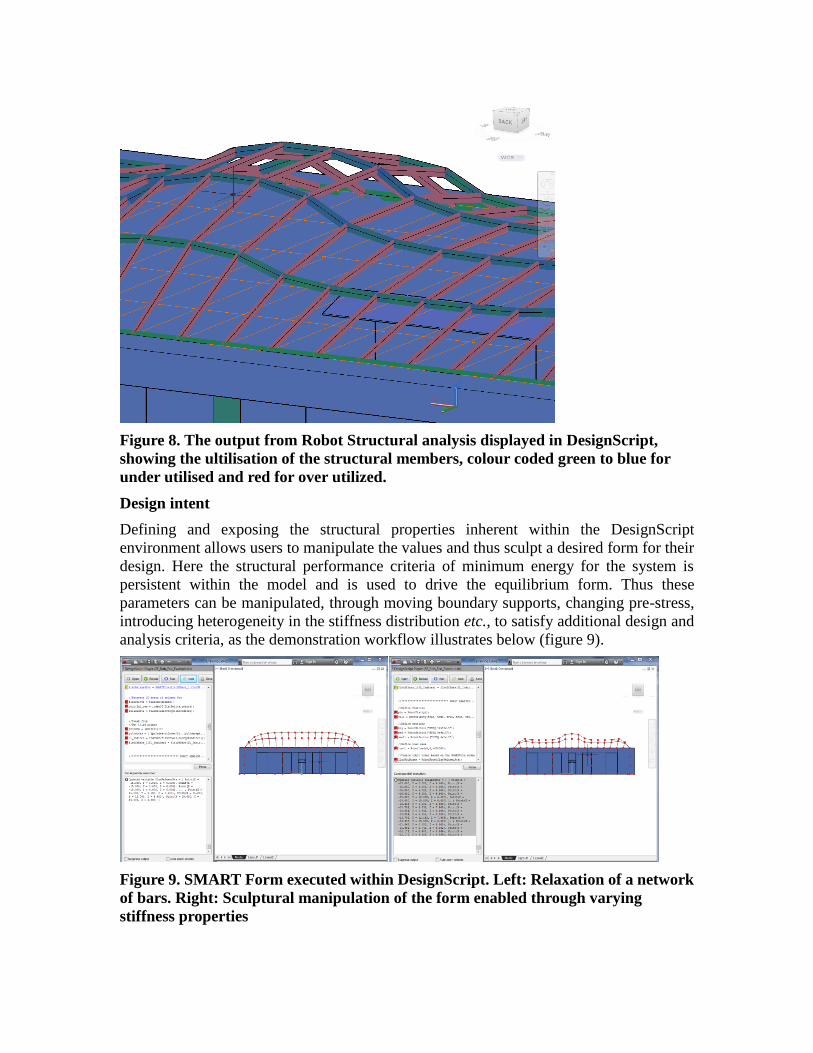
Figure 8. The output from Robot Structural analysis displayed in DesignScript,
showing the ultilisation of the structural members, colour coded green to blue for
under utilised and red for over utilized.
Design intent
Defining and exposing the structural properties inherent within the DesignScript
environment allows users to manipulate the values and thus sculpt a desired form for their
design. Here the structural performance criteria of minimum energy for the system is
persistent within the model and is used to drive the equilibrium form. Thus these
parameters can be manipulated, through moving boundary supports, changing pre-stress,
introducing heterogeneity in the stiffness distribution etc., to satisfy additional design and
analysis criteria, as the demonstration workflow illustrates below (figure 9).
Figure 9. SMART Form executed within DesignScript. Left: Relaxation of a network
of bars. Right: Sculptural manipulation of the form enabled through varying
stiffness properties
3.3 Ecotect integration
The Ecotect plug-in in this instance focused on solar design and analysis. The calculation
of instantaneous incident solar radiation is relatively straightforward as it involves just a
single sun position and everything can be readily solved geometrically. However, of
significantly more use to a designer are cumulative results such as the total collection over
the whole year or just for summer. This significantly increases the calculations required,
making these potentially very computationally expensive as they are highly dependent on
the geometric complexity of both the model and any potential obstructions that surround it.
Thus, rather than provide simple, high-level functions that return results for a given set of
date, time, location and geometry inputs, the aim in this work was to provide scope for
experimentation and usage patterns not envisaged by the plug-in developers, as well as
support interactive design feedback, which ideally requires calculation results as close to
real-time as possible.
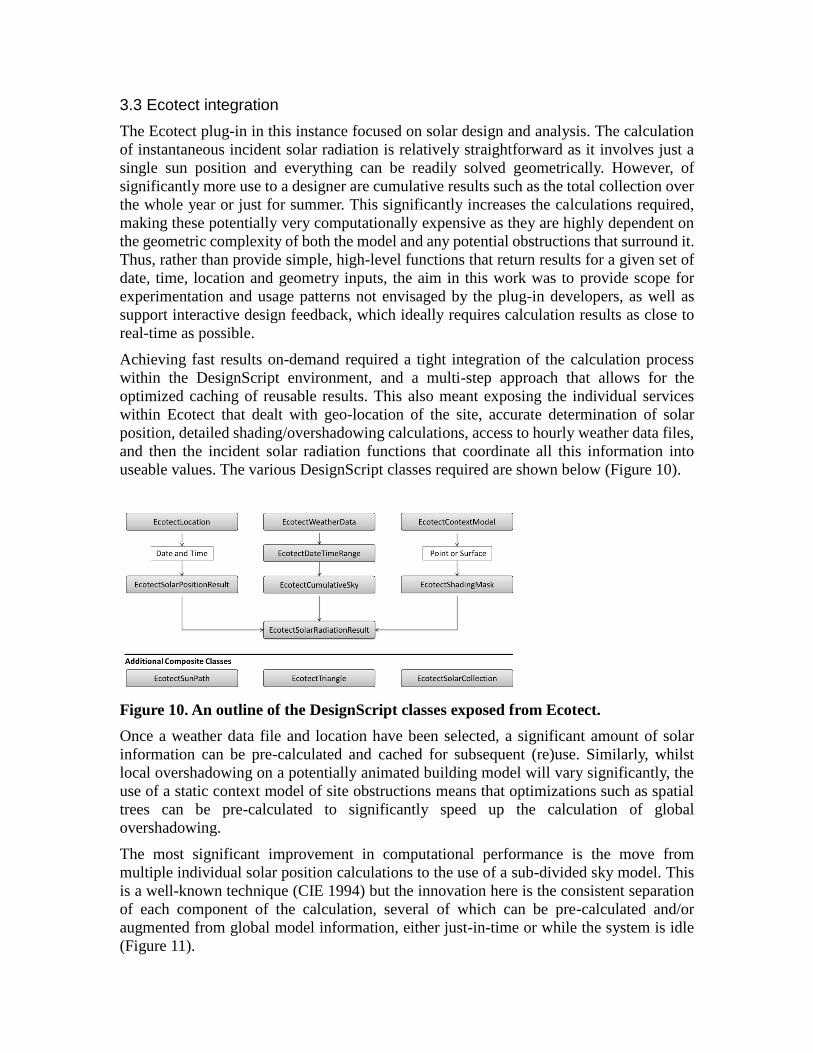
Achieving fast results on-demand required a tight integration of the calculation process
within the DesignScript environment, and a multi-step approach that allows for the
optimized caching of reusable results. This also meant exposing the individual services
within Ecotect that dealt with geo-location of the site, accurate determination of solar
position, detailed shading/overshadowing calculations, access to hourly weather data files,
and then the incident solar radiation functions that coordinate all this information into
useable values. The various DesignScript classes required are shown below (Figure 10).
Figure 10. An outline of the DesignScript classes exposed from Ecotect.
Once a weather data file and location have been selected, a significant amount of solar
information can be pre-calculated and cached for subsequent (re)use. Similarly, whilst
local overshadowing on a potentially animated building model will vary significantly, the
use of a static context model of site obstructions means that optimizations such as spatial
trees can be pre-calculated to significantly speed up the calculation of global
overshadowing.
The most significant improvement in computational performance is the move from
multiple individual solar position calculations to the use of a sub-divided sky model. This
is a well-known technique (CIE 1994) but the innovation here is the consistent separation
of each component of the calculation, several of which can be pre-calculated and/or
augmented from global model information, either just-in-time or while the system is idle
(Figure 11).
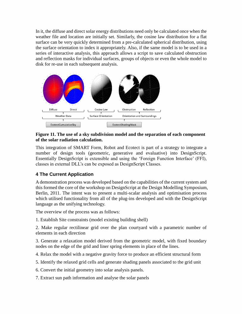
In it, the diffuse and direct solar energy distributions need only be calculated once when the
weather file and location are initially set. Similarly, the cosine law distribution for a flat
surface can be very quickly determined from a pre-calculated spherical distribution, using
the surface orientation to index it appropriately. Also, if the same model is to be used in a
series of interactive analysis, this approach allows a script to save calculated obstruction
and reflection masks for individual surfaces, groups of objects or even the whole model to
disk for re-use in each subsequent analysis.
Figure 11. The use of a sky subdivision model and the separation of each component
of the solar radiation calculation.
This integration of SMART Form, Robot and Ecotect is part of a strategy to integrate a
number of design tools (geometric, generative and evaluative) into DesignScript.
Essentially DesignScript is extensible and using the „Foreign Function Interface‟ (FFI),
classes in external DLL‟s can be exposed as DesignScript Classes.
4 The Current Application
A demonstration process was developed based on the capabilities of the current system and
this formed the core of the workshop on DesignScript at the Design Modelling Symposium,
Berlin, 2011. The intent was to present a multi-scalar analysis and optimisation process
which utilised functionality from all of the plug-ins developed and with the DesignScript
language as the unifying technology.
The overview of the process was as follows:
1. Establish Site constraints (model existing building shell)
2. Make regular rectilinear grid over the plan courtyard with a parametric number of
elements in each direction
3. Generate a relaxation model derived from the geometric model, with fixed boundary
nodes on the edge of the grid and liner spring elements in place of the lines.
4. Relax the model with a negative gravity force to produce an efficient structural form
5. Identify the relaxed grid cells and generate shading panels associated to the grid unit
6. Convert the initial geometry into solar analysis panels.
7. Extract sun path information and analyse the solar panels
8. Orient the panels based on this information
9. Obtain the overall insolation incident on the courtyard of the space
10. Modify the gravitational force of the relaxed grid (step 4) to influence the insolation on
the floor by reviewing the updated insolation analysis values
11. Develop a steel structural model with uniform sections based on the relaxed grid with
the same boundary conditions as the relaxation model.
12. Check the maximum stresses in each of the beams
13. Size up any failing beams and down any under-stressed beams in proportion to the
amount they are off the ideal utilisation of the material
14. Resize the base grid (step 2) and after the auto update of all the other modeling and
analysis systems, review whether the steel weights significantly change
This initial research demonstrated the capability of the system to support the design
decision process informed by appropriate and reliable performance criteria. The ability to
nest and reorder generative and analytical processes within the same overall computation
design environment is another important feature of the system. This allows the generation
of configurable hierarchies comprised of interrelated geometry generation, analysis and
decision making processes.
The system was initially tuned by the user and then subsequently by basic implementation
of a simple Newtonian goal seeking algorithm. The quality of actual optimisation
processes can be refined with more time and is the subject of the next research phase.
When demonstrated at the Berlin workshop, DesignScript with its set of plug-in‟s was
generally regarded with interest as a system with the capability for practical performance
driven design. The workshop participants spanned a broad range of architectural and
engineering experience and a number of the participants were able to take this model as a
starting point for their own exploration, including re-orienting the hierarchy of the design
logic towards their own intentions.
5 Future Research:
Based on the feedback from the DesignScript workshop…
There are number of interesting opportunities on the horizon for the next round of research:
Imperative Programming: With imperative programming being added to
DesignScript, the ability for practitioners to develop their own decision making and
optimisation routines exists. We are preparing for a second stage in the joint
research collaboration between the Autodesk DesignScript development team and
Buro Happold. Imperative programming will enable a general purpose genetic
algorithm to be developed for DesignScript.
Options Language and Cloud computing: The DesignScript is being extended
with a special „Options‟ language, which can be to control the generation of
multiple alternative design solution using cloud based parallelism. Design
optimisation, and specifically genetic algorithms require large number of solutions
to be generated. So this approach will be important in future design optimisation.
Conclusions:
The Multi-Criteria Design and Optimisation of buildings poses both an interesting
technical challenge and potentially a powerful means by which to drive design towards
better performance.
This paper shows a conceptual approach to supporting optimisation within a single
computational design system which crosses traditional discipline boundaries and can
therefore address issues of optimization which are inherently multi-disciplinary.
While the idea of design optimisation has been discussed in the research literature, it has
not been widely used in practice, mainly because tools based on optimization have not been
widely available or indeed available in forms which are easily accessible to practitioners.
Therefore, one important future challenges for software developers is to make
optimisations tools more accessible and more easily used by practitioners, but without
compromising the rigor of use that is required to achieve valid results. The anticipated
increase in adoption of optimisations tools has the potential to bring substantial benefits
not just to architects and building engineers but to the users and owners of buildings and
thereby address wider economic and sustainability concerns.
References
Whitehead, H. and Peters, B. (2008). Form and Complexity. In Space Craft: developments
in Architectural Computing. (ed) D. Littlefied, RIBA Enterprises.
Williams, C. (2001). The analytic and numerical definition of the geometry of the British
Museum Great Court Roof. In Mathematics and Design (eds ) M. Burry, S. Datta, A.
Dawson, and A. J. Rollo, 434-440, Deakin University, Geelong, Victoria 3217,
Australia, 2001.
Aish, R. (2011). DesignScript: origins, explanation, illustration, Design Modeling
Symposium, University of the Arts, Berlin
Evins, R., Joyce, S. et al (2012). Multi-objective optimisation: getting more for less by
design, Proceedings of the Institution of Civil Engineers, Civil Engineering Special
Issue 165.
Shrubshall, C., Fisher, A. (2011). The Practical Application of Structural Optimisation in
the Design of the Louvre Abu Dhabi. In: Proceedings of the International Association
for Shell and Spatial Structures Symposium. London.
Attar, R., Aish, R., Stam, J., et al (2009) Physics-based generative design, CAAD Futures.
Commission Internationale de l'Eclairage Guide to recommended practice of daylight
measurement (1994). (ed) J D Kendrick, Vienna: Commission Internationale de
l'Eclairage.