Embed Size (px)
Citation preview
PROJECT MANUAL
BAS UPGRADE
RIVERSIDE SCHOOL
90 HENDRIE AVENUE
RIVERSIDE, CT
BID #2205-18
MAY 11, 2018
ISSUED FOR BID
MEP ENGINEER:
LANDMARK FACILITIES GROUP, INC.
252 EAST AVENUE
NORWALK , CT 06855
Greenwich Public Schools Riverside School BAS Upgrade
2
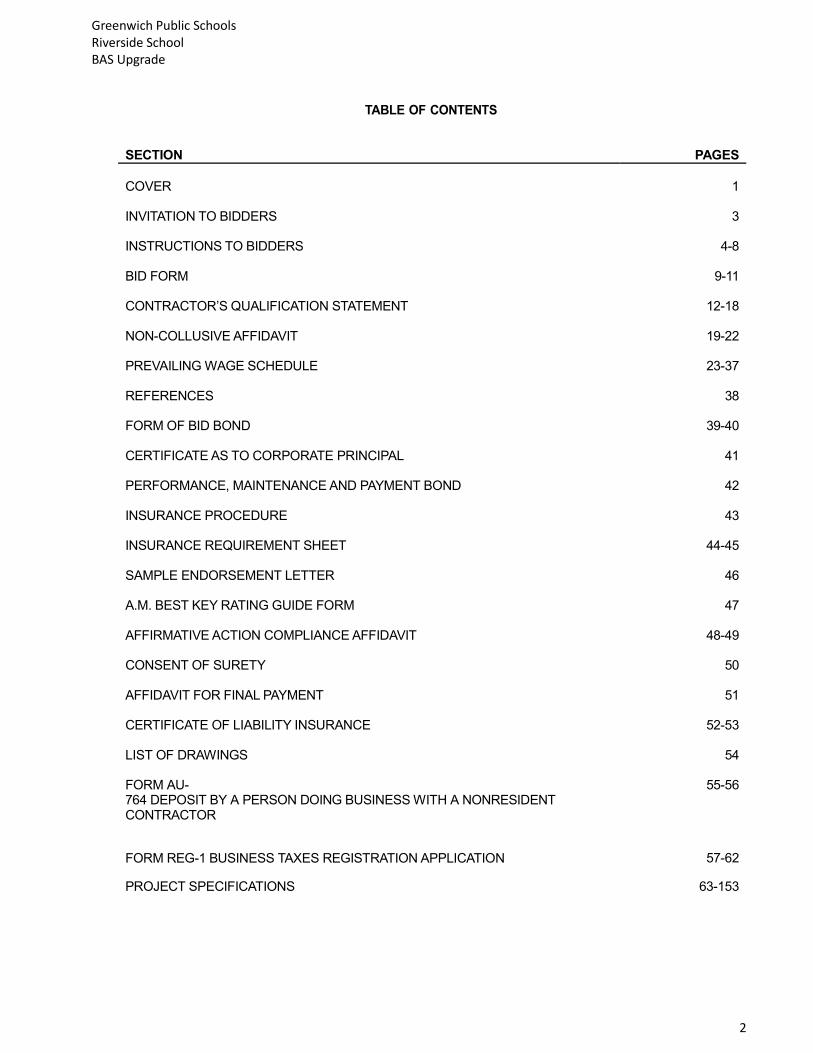
TABLE OF CONTENTS
SECTION PAGES
COVER 1 INVITATION TO BIDDERS 3 INSTRUCTIONS TO BIDDERS 4-8 BID FORM 9-11 CONTRACTOR’S QUALIFICATION STATEMENT 12-18 NON-COLLUSIVE AFFIDAVIT 19-22 PREVAILING WAGE SCHEDULE 23-37 REFERENCES 38 FORM OF BID BOND 39-40 CERTIFICATE AS TO CORPORATE PRINCIPAL 41 PERFORMANCE, MAINTENANCE AND PAYMENT BOND 42 INSURANCE PROCEDURE 43 INSURANCE REQUIREMENT SHEET 44-45 SAMPLE ENDORSEMENT LETTER 46 A.M. BEST KEY RATING GUIDE FORM 47 AFFIRMATIVE ACTION COMPLIANCE AFFIDAVIT 48-49 CONSENT OF SURETY 50 AFFIDAVIT FOR FINAL PAYMENT 51 CERTIFICATE OF LIABILITY INSURANCE 52-53 LIST OF DRAWINGS 54 FORM AU-764 DEPOSIT BY A PERSON DOING BUSINESS WITH A NONRESIDENT CONTRACTOR
55-56
FORM REG-1 BUSINESS TAXES REGISTRATION APPLICATION 57-62
PROJECT SPECIFICATIONS 63-153

Greenwich Public Schools Riverside School BAS Upgrade
3
GREENWICH PUBLIC SCHOOLS Purchasing Department 290 Greenwich Ave. Greenwich, Connecticut 06830 (203) 625-7400 Fax (203) 625-7677 EUGENE H. WATTS Senior Buyer MAY 11, 2018 Dear Sir/ Madam: You are invited to submit a bid for a BAS Upgrade Project for Riverside School. This bid will be a lump sum for your work and material in accordance with the plans and specifications contained herein. Bidders are urged to read all documents carefully and provide all information requested. Bids which are Incomplete, conditional, or contain irregularities of any kind, will be subject to rejection. Bids must be submitted on the schedule form attached hereto. All unit prices must be filled in. Each bid must be submitted with one (1) original and three (4) copies of the bid. Bidders must submit bids in a clear, concise, and legible manner so as to permit proper evaluation of responsive bids. Faxed bids will not be accepted. The original bid and copies must be placed in a sealed plainly marked envelope bearing the following: BAS Upgrade (Riverside Elementary School) - BID NUMBER: 2205-18 KEY PROJECT DATES
A. Mandatory pre-bid walk through: 1. Wednesday May 16, 2018 at 3:30 pm. Riverside School (Main Entrance). B. Bid Due Date: 1. Sealed proposals will be received as indicated below, and at that time and place will be publicly opened and read aloud. 2. Date: June 1, 2018 3. Time: 11:00 AM local time 4. Location: District Offices 5. Address: GREENWICH PUBLIC SCHOOLS, 290 Greenwich Ave., Greenwich, Connecticut 06830, (203) 625-7411 6. 7. All bidders are invited to attend the opening of bids. Additional information for bidding is provided in the Instructions to Bidders. Very truly yours, Eugene H. Watts
Greenwich Public Schools Riverside School BAS Upgrade
4
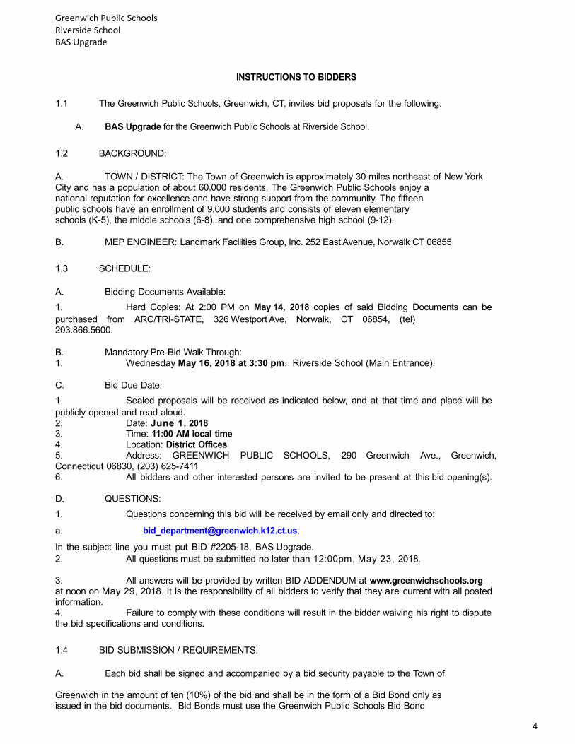
INSTRUCTIONS TO BIDDERS
1.1 The Greenwich Public Schools, Greenwich, CT, invites bid proposals for the following:
A. BAS Upgrade for the Greenwich Public Schools at Riverside School.
1.2 BACKGROUND:
A. TOWN / DISTRICT: The Town of Greenwich is approximately 30 miles northeast of New York City and has a population of about 60,000 residents. The Greenwich Public Schools enjoy a national reputation for excellence and have strong support from the community. The fifteen public schools have an enrollment of 9,000 students and consists of eleven elementary schools (K-5), the middle schools (6-8), and one comprehensive high school (9-12).
B. MEP ENGINEER: Landmark Facilities Group, Inc. 252 East Avenue, Norwalk CT 06855
1.3 SCHEDULE:
A. Bidding Documents Available:
1. Hard Copies: At 2:00 PM on May 14, 2018 copies of said Bidding Documents can be
purchased from ARC/TRI-STATE, 326 Westport Ave, Norwalk, CT 06854, (tel) 203.866.5600.
B. Mandatory Pre-Bid Walk Through: 1. Wednesday May 16, 2018 at 3:30 pm. Riverside School (Main Entrance).
C. Bid Due Date:
1. Sealed proposals will be received as indicated below, and at that time and place will be
publicly opened and read aloud. 2. Date: June 1, 2018 3. Time: 11:00 AM local time 4. Location: District Offices 5. Address: GREENWICH PUBLIC SCHOOLS, 290 Greenwich Ave., Greenwich, Connecticut 06830, (203) 625-7411 6. All bidders and other interested persons are invited to be present at this bid opening(s). D. QUESTIONS:
1. Questions concerning this bid will be received by email only and directed to:
In the subject line you must put BID #2205-18, BAS Upgrade.
2. All questions must be submitted no later than 12:00pm, May 23, 2018.
3. All answers will be provided by written BID ADDENDUM at www.greenwichschools.org at noon on May 29, 2018. It is the responsibility of all bidders to verify that they are current with all posted information. 4. Failure to comply with these conditions will result in the bidder waiving his right to dispute the bid specifications and conditions.
1.4 BID SUBMISSION / REQUIREMENTS:
A. Each bid shall be signed and accompanied by a bid security payable to the Town of Greenwich in the amount of ten (10%) of the bid and shall be in the form of a Bid Bond only as issued in the bid documents. Bid Bonds must use the Greenwich Public Schools Bid Bond
Greenwich Public Schools Riverside School BAS Upgrade
5
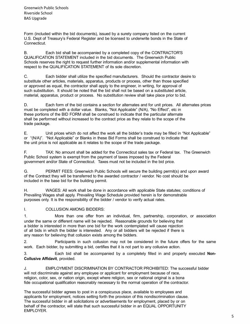
Form (included within the bid documents), issued by a surety company listed on the current U.S. Dept of Treasury’s Federal Register and be licensed to underwrite bonds in the State of Connecticut.
B. Each bid shall be accompanied by a completed copy of the CONTRACTOR'S QUALIFICATION STATEMENT included in the bid documents. The Greenwich Public Schools reserves the right to request further information and/or supplemental information with respect to the QUALIFICATION STATEMENT of its sole discretion.
C. Each bidder shall utilize the specified manufacturers. Should the contractor desire to substitute other articles, materials, apparatus, products or process, other than those specified or approved as equal, the contractor shall apply to the engineer, in writing, for approval of such substitution. It should be noted that the bid shall not be based on a substituted article, material, apparatus, product or process. No substitution review shall take place prior to bid.
D. Each form of the bid contains a section for alternates and for unit prices. All alternates prices must be completed with a dollar value. Blanks, “Not Applicable” (N/A), “No Effect”, etc in these portions of the BID FORM shall be construed to indicate that the particular alternate shall be performed without increased to the contract price as they relate to the scope of the trade package.
E. Unit prices which do not affect the work all the bidder’s trade may be filled in “Not Applicable” or “(N/A)”. “Not Applicable” or Blanks in these Bid Forms shall be construed to indicate that the unit price is not applicable as it relates to the scope of the trade package.
F. TAX: No amount shall be added for the Connecticut sales tax or Federal tax. The Greenwich Public School system is exempt from the payment of taxes imposed by the Federal government and/or State of Connecticut. Taxes must not be included in the bid price.
G. PERMIT FEES: Greenwich Public Schools will secure the building permit(s) and upon award of the Contract they will be transferred to the awarded contractor / vendor. No cost should be included in the base bid for the building permit.
H. WAGES: All work shall be done in accordance with applicable State statutes; conditions of Prevailing Wages shall apply. Prevailing Wage Schedule provided herein is for demonstrable purposes only. It is the responsibility of the bidder / vendor to verify actual rates.
I. COLLUSION AMONG BIDDERS:
1. More than one offer from an individual, firm, partnership, corporation, or association
under the same or different name will be rejected. Reasonable grounds for believing that a bidder is interested in more than one bid for the work contemplated will cause rejection of all bids in which the bidder is interested. Any or all bidders will be rejected if there is any reason for believing that collusion exists among the bidders.
2. Participants in such collusion may not be considered in the future offers for the same
work. Each bidder, by submitting a bid, certifies that it is not part to any collusive action.
3. Each bid shall be accompanied by a completely filled in and properly executed Non-
Collusive Affidavit, provided.
J. EMPLOYMENT DISCRIMINATION BY CONTRACTOR PROHIBITED: The successful bidder will not discriminate against any employee or applicant for employment because of race, religion, color, sex, or nation origin, except where religion, sex or national original is a bona fide occupational qualification reasonably necessary to the normal operation of the contractor. The successful bidder agrees to post in a conspicuous place, available to employees and applicants for employment, notices setting forth the provision of this nondiscrimination clause. The successful bidder in all solicitations or advertisements for employment, placed by or on behalf of the contractor, will state that such successful bidder in an EQUAL OPPORTUNITY EMPLOYER.
Greenwich Public Schools Riverside School BAS Upgrade
6
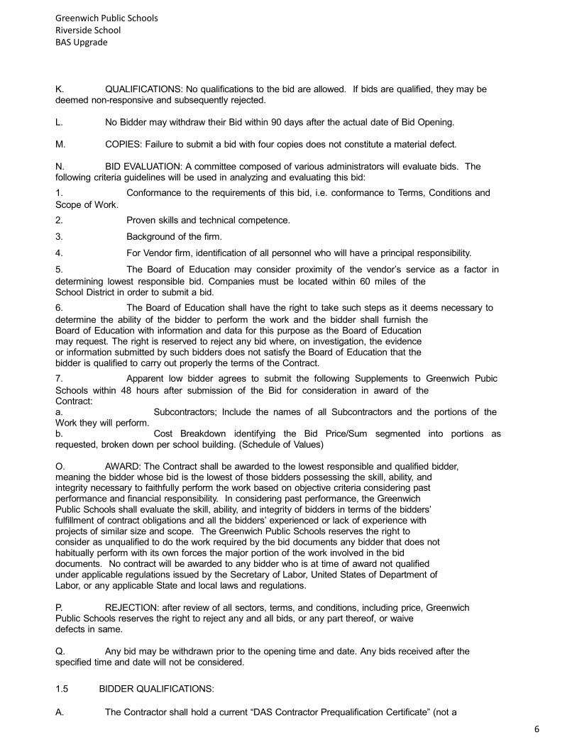
K. QUALIFICATIONS: No qualifications to the bid are allowed. If bids are qualified, they may be deemed non-responsive and subsequently rejected.
L. No Bidder may withdraw their Bid within 90 days after the actual date of Bid Opening.
M. COPIES: Failure to submit a bid with four copies does not constitute a material defect.
N. BID EVALUATION: A committee composed of various administrators will evaluate bids. The following criteria guidelines will be used in analyzing and evaluating this bid:
1. Conformance to the requirements of this bid, i.e. conformance to Terms, Conditions and
Scope of Work.
2. Proven skills and technical competence.
3. Background of the firm.
4. For Vendor firm, identification of all personnel who will have a principal responsibility.
5. The Board of Education may consider proximity of the vendor’s service as a factor in
determining lowest responsible bid. Companies must be located within 60 miles of the School District in order to submit a bid.
6. The Board of Education shall have the right to take such steps as it deems necessary to
determine the ability of the bidder to perform the work and the bidder shall furnish the Board of Education with information and data for this purpose as the Board of Education may request. The right is reserved to reject any bid where, on investigation, the evidence or information submitted by such bidders does not satisfy the Board of Education that the bidder is qualified to carry out properly the terms of the Contract.
7. Apparent low bidder agrees to submit the following Supplements to Greenwich Pubic
Schools within 48 hours after submission of the Bid for consideration in award of the Contract: a. Subcontractors; Include the names of all Subcontractors and the portions of the Work they will perform. b. Cost Breakdown identifying the Bid Price/Sum segmented into portions as requested, broken down per school building. (Schedule of Values)
O. AWARD: The Contract shall be awarded to the lowest responsible and qualified bidder, meaning the bidder whose bid is the lowest of those bidders possessing the skill, ability, and integrity necessary to faithfully perform the work based on objective criteria considering past performance and financial responsibility. In considering past performance, the Greenwich Public Schools shall evaluate the skill, ability, and integrity of bidders in terms of the bidders’ fulfillment of contract obligations and all the bidders’ experienced or lack of experience with projects of similar size and scope. The Greenwich Public Schools reserves the right to consider as unqualified to do the work required by the bid documents any bidder that does not habitually perform with its own forces the major portion of the work involved in the bid documents. No contract will be awarded to any bidder who is at time of award not qualified under applicable regulations issued by the Secretary of Labor, United States of Department of Labor, or any applicable State and local laws and regulations.
P. REJECTION: after review of all sectors, terms, and conditions, including price, Greenwich Public Schools reserves the right to reject any and all bids, or any part thereof, or waive defects in same.
Q. Any bid may be withdrawn prior to the opening time and date. Any bids received after the specified time and date will not be considered.
1.5 BIDDER QUALIFICATIONS:
A. The Contractor shall hold a current “DAS Contractor Prequalification Certificate” (not a

Greenwich Public Schools Riverside School BAS Upgrade
7
predetermination letter) from the Department of Administrative Services of the State of Connecticut according to Connecticut General Statutes Section 4a-100, 4b-101, 4b-91, previously stated as Public Act 03-215 and as amended by Public Act 04-141.
B. Bidders shall submit with their bids a “DAS Contractor Prequalification Certificate” as well as a current “Update (bid) Statement”.
C. Questions regarding these requirements should be directed to the State of Connecticut, DAS. Contact information can be found at www.das.state.ct.us.
D. Companies must be located within 60 miles of the School District in order to submit a bid.
E. Companies submitting a bid must be in business under the same corporate name for a minimum of five (5) years.
F. Non-Connecticut Contractors: Pursuant to Connecticut General Statutes §12-430(7), as amended by Public Act No. 11-61, Section 66, a non-resident contractor shall comply with the State of Connecticut’s bonding requirements.
1.6 CONTRACT:
A. SINGLE PRIME CONTRACT will be let for:
1. General Construction
2. Bid awards must be approved by the Greenwich Public Schools. All contractors shall be
required to execute the Greenwich Public Schools standard form of Contract and accompanying Payment & Performance Bonds without exception. B. LENGTH: This bid is for awarding the contract to cover the period beginning July 2, 2018. Once this Bid is awarded, successful bidder must make arrangements to meet with Greenwich Public Schools as required.
C. OPTION TO EXTEND: All work associated with the project shall be completed on or before August
24, 2018. The Board of Education may, at their option and with the approval of the vendor, extend the period of the Contract to December 14, 2018. If the Board of
Education intends to extend the contract period, the vendor shall be notified in writing by the purchasing department at least fourteen (14) calendar days prior to the expiration of the original contract.
D. AWARD OF CONTRACT: The contract will be awarded by the Board of Education to a qualified firm or person at compensation determined to be fair and reasonable considering budgetary limitations, scope, complexity, and the nature of goods and/or services.
1. If there is a conflict between the Contract Agreement and the General Conditions, the
Contract Agreement shall prevail.
2. The successful bidder will produce for the Greenwich Public Schools review a current
financial statement, which will remain strictly confidential.
E. The contractor shall simultaneously with the signing of the Contract, furnish the Town the executed Performance, Maintenance, and Payment Bond of a surety company authorized to do business the State of Connecticut, and acceptable to the Town, in the sum of all the full amount of the Contract Obligation in the form provided by the Town. The Performance Bond will not be required where the total estimated cost of labor and materials under the contract with respect to which such general bid is submitted is less than one hundred thousand dollars ($100,000). Once a contract exceeds $100,000 the bidder will be responsible for obtaining and paying for all bonds required by Greenwich Public Schools.

Greenwich Public Schools Riverside School BAS Upgrade
8
F. FEE PAYMENTS: The Greenwich Public Schools reserves the right to provide payment in accordance with completion of services based on the Project Schedule.
PART 2 - PRODUCTS (Not Applicable) PART 3 - EXECUTION
3.1 PROVISIONS:
A. Consumption or use of alcohol and / or drugs is prohibited on school property. Any individual with alcohol or drugs will be removed from said property and will not be allowed to work on the project. Smoking is prohibited in all school buildings and on school grounds.
B. Greenwich Public Schools reserves the right to reject any proposed subcontractor for reasonable cause.

Greenwich Public Schools Riverside School BAS Upgrade
9
BID FORM The undersigned hereby proposes to furnish all labor, materials, devices, appliances, supplies, equipment, services and other facilities necessary to complete all of the work of the above referenced Contract, as required by, and in accordance with, the provisions of the Instructions to Bidders, the Conditions of the Contract, the Drawings and Specifications, all as prepared by Landmark Facilities Group, Inc. dated May 11, 2018; and that, if this Proposal is accepted, the Undersigned agrees to enter into an Agreement with the Owner to perform this work for the sum(s) as follows: SUBMITTED BY: ______________________________________________________________ Bidder’s Full Name _____________________________________________________________ Address ______________________________________________________________________ _____________________________________________________________________________ City, State, Zip 1.1 BASE BID VALUE: A. BASE BID: The Base Bid Proposal for all work required by the Contract Document for the BAS Upgrade Project at RIVERSIDE SCHOOL and Related Work is as follows: _______________________________________________ ($ )DOLLARS 1.2 ALTERNATE VALUES: The values of Alternates to the Base Bid amount are identified below.
1. Alternate #1______________________ _________________. 2. Alternate #2______________________ __________________. 3. Alternate #3______________________ __________________. 4. Alternate #4______________________ __________________. 5. Alternate #5______________________ __________________. 6. Alternate #6______________________ __________________.
1.3 ACCEPTANCE: A. If this bid is accepted by Greenwich Public Schools within the time period stated above, we will:
1. Execute the Agreement within seven days of receipt of Notice of Award.
2. Furnish the required bonds within seven days of receipt of Notice of Award. B. If this bid is accepted within the time stated, and we fail to commence the Work or we fail to provide the required Bond(s), the security deposit shall be forfeited as damages to Greenwich Public Schools by reason of our failure, limited in amount to the lesser of the face value of the security deposit or the difference between this bid and the bid upon which a Contract is signed.
1.4 CONTRACT TIME: A. The Undersigned agrees in the Base Bid to complete the work as per the Milestone Schedule provided in the Specifications.

Greenwich Public Schools Riverside School BAS Upgrade
10
1.5 ADDENDA: A. The following Addenda have been received. The modifications to the Bid Document noted below have been considered and all cost are included in the Bid Sum.
1. Addendum#______________________ Date__________________. 2. Addendum#______________________ Date__________________. 3. Addendum#______________________ Date__________________. 4. Addendum#______________________ Date__________________. 5. Addendum#______________________ Date__________________.
1.6 BIDDER’S FURTHER AFFIRMATION AND DECLARATION A. The above name bidder and should this bid be a joint bid each party thereto, further affirm and declares;
1. That said bidder is of lawful age and the only one interested in this bid; and that no other person, firm or corporation, except those herein above names has any interest in this bid or in the contract proposed to be entered into.
2. That said bidder is not in arrears to the Greenwich Public School upon debt or contract, and is not a defaulter, as surety or otherwise upon any obligation to the Greenwich Public Schools.
3. That no member of the Greenwich Public Schools or any officer or employee of the Greenwich Public School or person whose salary is payable in whole or in part from the School District treasury, or the spouse of any foregoing is or shall be or become interested, directly or indirectly, as a contracting party, partner, stockholder, surety or otherwise, in this bid, or in the performance of the Contract, or in the supplies, materials or equipment and work or labor to which it relates, or in any portion of the profits thereof.
4. That he/she has carefully examined the site of the work and that, from his / her own investigations, he/ she has satisfied him/ herself as to the nature and location of the work, and character, quality and quantity of material, and all difficulties likely to be encountered, the kind and extent of equipment and other facilities needed for the performance of the work, the general and local conditions, and all other items which may, in any way, effect the work or its performance.
5. That if a corporation, this bid or proposal containing the Non-Collusive Binding Certification and the foregoing Affirmation and Declaration has been authorized by the Board of Directors of such Corporation, which authorization includes the signing and submission of this bid or proposal and the inclusion therein of the said Certificate of Non-Collusion and Affirmation and Declaration as the Act and Dees of the Corporation.
Greenwich Public Schools Riverside School BAS Upgrade
11
BID FORM SIGNATURE(S) _________________________________________________________________ Signature Corporate Seal Company Name:____________________________________________________ was hereunto affixed in the presence of: __________________________________________________________________ Subscribed and sworn before me this day of ______ 2018 Notary Public:______________________________________________________ My Commission Expire:______________________________________________

Greenwich Public Schools Riverside School BAS Upgrade
12
CONTRACTOR’S QUALIFICATION STATEMENT
With the submittal of the Bid Proposal Form (Section 00 0400), the bidder shall attach this Contractor's Qualification Statement and shall answer the Questions herein. Failure to answer these questions in full may be cause for rejection of the bidder’s proposal. If more space is needed, please attach other sheets with reference to subject paragraph.
The Board of Education reserves the right to consider, but not limited to, the financial responsibility, experience and reputation in the construction industry, as well as the specific qualifications listed below and elsewhere in this document in considering bids and awarding the contract. The Board of Education reserves the right to waive any informalities if, at its discretion the interest of the Greenwich Public Schools will be better served.
The Undersigned certifies under oath that the information provided herein is true and sufficiently complete so as not to be misleading. SUBMITTED TO: Greenwich Public Schools ADDRESS: 290 Greenwich Avenue, Greenwich, CT 06830
SUBMITTED BY: Corporation NAME Partnership ADDRESS: Individual PRINCIPAL OFFICE Other
NAME OF PROJECT: BAS Upgrade – Riverside School TYPE OF WORK (file separate for each Classification of Work)
____________General Construction ___________HVAC
____________Plumbing ___________Electrical ____________Other ___________Fire Alarm 1.1 ORGANIZATION A. How many years has your organization been in business as a Contractor? B. How many years has your organization been in business under its present business name? 1. Under what other or former names has your organization operated? C. What is the firm’s bonding range? 1. Single 2. Aggregate D. If your organization is a corporation, answer the following: 1. Date of Incorporation: 2. State of Incorporation: 3. President’s name:

Greenwich Public Schools Riverside School BAS Upgrade
13
4. Vice-president’s name(s): 5. Secretary’s name: 6. Treasurer’s name: E. If your organization is a partnership, answer the following: 1. Date of organization: 2. Type of partnership (if applicable): 3. Name(s) of general partner(s): F. If your organization is individually owned, answer the following: 1. Date of organization: 2. Name of owner: G. If the form of your organization is individually owned, answer the following: 1. If the form of your organization is other than those listed above, describe it and name the principals: 1.2 OWNERSHIP, MANAGEMENT, AFFILIATION A. Identify each person who is or has been within the past five years, an owner of 5.0% or more of the firm’s shares, one of the five largest shareholders, a director, an officer, a partner or the proprietor, or a managerial employee.
First Name MI Last Name DOB % Owned Director Y or N
Officer Y or N
Title Partner Y or N

Greenwich Public Schools Riverside School BAS Upgrade
14
B. Joint Ventures: Provide information for all firms involved. Fill in name, % owned, office held; indicate by Y or N whether director, officer, partner and title.
First Name MI Last Name DOB % Owned Director Y or N
Officer Y or N
Title Partner Y or N
C. Identify any other firms in which now or in the past five years, the firm or any of the individuals listed in questions 1.2.A and 1.2.B above, either owned or owns 5.0% or more of the shares of or was or is one of the five largest shareholders, a director, an officer, a partner or a proprietor of said other firm. ______Yes, list below ________No
D Has the firm or any firm listed in response to questions above defaulted or been terminated and its surety called upon to complete, any contract awarded within the past five years ( ) Yes, (
) No. If yes, give date(s), agency(ies)/owner(s), project(s), contract numbers, and describe including the result: E. List below any projects performed by the bidder in the past five (5) years on which any of the following events occurred: F. 1. Were any extension of time requested by the contractor, and were such requests granted? 2. Was litigation and/or arbitration commenced by either the Owner or the bidder as a result of the work of the project performed by the bidder? 3. Were any liens filed on the project by subcontractors or material suppliers of the bidder? 4. Did the bidder make any claims for extra work on the project, and did said claim result in a change order?
Project Type of Event Name/Address of Owner Name & Phone # of Contact Person at Owner
G. For all contracts within the past five years: (a) List all liens or claims over $25,000 filed against the firm and remaining undischarged or unsatisfied for more than 90 days; and (b) list and describe all liquidated damages assessed. 1.3 FINANCIAL INFORMATION A. Provide a copy of the firm’s most recent annual financial statement.
Federal ID No. % Owned Firm/Company Name: Position Company Address

Greenwich Public Schools Riverside School BAS Upgrade
15
1.4 OTHER INFORMATION A. Within the past five years has the firm, any affiliate, any predecessor company or entity or any person identified in questions number 1.1 through 1.2 above been the subject of any of the following: (Respond to each question and describe in detail the circumstances of each affirmative answer: (Attach additional pages if necessary).
1. A judgment of conviction for any business-related conduct
constituting a crime under state or federal law.
No
Yes
2. A criminal investigation or indictment for any business-related conduct constituting a crime under state or federal law?
No
Yes
3. An order of protection filed against an officer or employee prohibiting access to jobsite(s) or prohibiting contact with any staff of any owner?
No
Yes
4. A grant of immunity for any business-related conduct constituting a crime under state and federal law?
No
Yes
5. A federal or state suspension or debarment? No Yes
6. A rejection of any bid for lack of qualifications, responsibility or because of the submission or an informal, non-responsive or incomplete bid?
No
Yes
7. A rejection of any proposed subcontract for lack of qualifications, responsibility or because of the submission or an informal, non-
responsive or incomplete bid?
No
Yes
8. A denial or revocation of prequalication? No Yes
9. A voluntary exclusion from bidding/contracting agreement? No Yes
10. Any administrative proceeding or civil action seeking specific performance or restitution in connection with any public works contract except any disputed work proceeding?
No
Yes
11. An OSHA Citation and Notification of Penalty containing a violation classified as serious?
No
Yes
12. An OSHA Citation or Notification of Penalty containing a a violation classified as willful?
No
Yes
13. A prevailing wage or supplement payment violation? No Yes
14. A State Labor Law violation deemed willful? No Yes
15. Any other federal or state Citations, Notices, violation orders, pending administrative hearings or proceedings or determinations of a violation of any labor law or regulation?
No
Yes
16. Any criminal investigation, felony indictment or conviction concerning formation of or any business association with, an allegedly false or fraudulent women’s, minority or disadvantaged business enterprise?
No
Yes
17. Any denial, decertification, revocation or forfeiture of Women’s Business Enterprise, Minority Business Enterprise or Disadvantaged Business Enterprise status?
No
Yes
18. Rejection of a low bid on a State contract for failure to meet statutory affirmative action M/WBE requirements?
No
Yes
19. A consent order with the NYS Department of Environmental Conservation or a federal, state or local government enforcement determination involving a violation of federal or state environmental laws?
No
Yes
20. Any bankruptcy proceeding? No Yes
21. Any suspension or revocation of any business or professional license?
No
Yes
22. Any citations, notices, violation orders, pending administrative hearings or proceedings or determinations for violation of:
No
Yes

Greenwich Public Schools Riverside School BAS Upgrade
16
No______Yes_____ Federal, state or local health laws, rules or regulations?
Federal, state or local environmental laws, rules and regulations? No Yes Unemployment insurance or workers compensation coverage or claim requirements?
No
Yes
ERISA (Employee Retirement Income Security Act)? No Yes
Federal, state or local human rights laws? No Yes
Federal or state security laws? No Yes
23. Withdrawal or an agreement to withdraw a bid submitted to a public owner or a request by a public owner to withdraw a bid?
No
Yes
24. During the five year period preceding the submission of this bid, has
the bidder been named as a part in any lawsuit in an action involving
a claim for personal injury or wrongful death arising from the
performance of work related to any project in which it has been
engaged? If the answer to the question is yes, list all such lawsuits,
the index number associated with said lawsuit and the status of the
lawsuit at the time of the submission of this bid.
No
Yes
25. During the five year period preceding the submission of this bid, has
the bidder been the subject of proceedings before the Department of
Labor for alleged violations of the Labor Law as it related to the
payment of prevailing wages and/or supplemental payment
requriements? If the answer to the question is yes, list each such
instance of the commencement of a Department of Labor
proceeding, for which project such proceeding was commenced, and
the status of the proceeding at the time of the submission of this bid.
No
Yes
26. During the five year period preceding the submission of this bid, has
the bidder been the subject of proceedings involving allegations that
it violated the Worker’s Compensation Law including but not limited
to the failure to provide proof of worker’s compensation or disability
coverage and/or any lapses thereof? If the answer to the question is
yes, list such instsance of violation and the status of the claimed
violation at the time of disposition of this bid.
No
Yes
27. Has the bidder, its officers, directors, owner and/or managerial
employees been convicted of a crime of been the subject of a
criminal indictment during the five years preceding the submission of
this bid? If the answer to the question is yes, list the name of the
individual convicted or indicted, the charge against the individual and
the date of disposition of the charge.
No
Yes
28. During the five year period preceding the submission of this bid, has
the bidder been charged with and/or found guilty of any violations of
federal, state or municipal environmental and/or health laws, codes,
rules and/or regulations? If the answer to the question is yes, list the
nature of the charge against the bidder, the date of the charge, and
the status of the charge at the time of the submission of this bid.
No
Yes
29. Has the bidder ever defaulted or had its surety called upon to
complete any contract awarded within the past five years? If the
answer to the question is yes, list the projects, the dates and the
nature of the termination (convenience, suspension, for cause).
No
Yes
30. Has any officer or partner of the bidder’s organization ever defaulted
or had its surety called upon to complete any contract awarded within
the past five years or been an office or partner of some other
organization that has been terminated from a project by an owner? If
yes, state:
No
Yes

Greenwich Public Schools Riverside School BAS Upgrade
17
Name of Individual Name of Organization Reason(s)
C. LICENSING 1. List jurisdictions and trade categories in which your organization is legally qualified to do business, and indicate registration of license numbers, if applicable. 2. List jurisdictions in which your organization’s partnership or trade name is filed: 3. Has any director, officer, owner or managerial employee had any professional license suspended or revoked? If the answer is yes, list the name of the individual, the professional license he/she formally had, whether the license was revoked or suspended and the date of the revocation or suspension. No______ Yes_____ 1.5 EXPERIENCE A. List the categories of work that your organization will perform with its own forces: 1. Claims and Suits. (If the answer of any of the questions below is yes, please attach details.)
a. Have you or has any director, officer, owner or managerial employee ever failed to complete any work awarded to them? If yes, list the project(s) the date(s) and the reason(s) for the failure to complete.
No
Yes
b. Are there any judgments, claims, arbitration proceedings or suits pending or outstanding against your organization or its officers?
No
Yes
c. Has your organization filed any law suits or requested arbitration with regard to construction contracts
within the last five years?
No
Yes
d. Within the past five years, has any officer or principal of your organization ever been an officer or a principal of another organization when it failed to complete a construction contract? If the answer is yes, please attach details.
No
Yes
. B. On a separate sheet, list all similar construction projects your organization has in progress or completed, giving the name of project, owner, engineer, contract amount, percent complete and scheduled completion date. 1. State total worth of work in progress and under contract: C. On a separate sheet, list all projects, not listed above, that your organization has completed or in progress in the past five years, giving the name of the project, owner, engineer, contract amount, date of completion and percentage of the cost of the work performed with your own forces. 1. State average annual amount of construction work performed during the past five years: D. On a separate sheet, list the construction experience and present commitment of the key individuals of your organization. 1.6 REFERENCES A. Trade reference: B. Bank references: C. Surety: 1. Name of present bonding company:

Greenwich Public Schools Riverside School BAS Upgrade
18
2. Name and address of agent: 3. Name or previous bonding company: 1.7 CERTIFICATION A. The undersigned recognizes that this questionnaire is submitted for the purpose of the Greenwich Public Schools (Owner) to award a contract or approve a subcontract; acknowledges that the Owner may in its discretion, by means which it may choose, determine the truth and accuracy of all statements made herein; acknowledge that intentional submission of false or misleading information may constitute a felony, or a misdemeanor, and may also be punishable by a fine or imprisonment; and states that the information submitted in this questionnaire and any attached pages is true, accurate and complete. B. Dated at this day of ___________ ___________________________________________________________________________ Name of Organization: _________________________________________________________________ By: ______________________________________________________________________ Title:
SWORN AND SUBSCRIBED TO BEFORE ME, A NOTARY PUBLIC, IN AND FOR THE COUNTY OF ____________________ AND THE STATE OF __________________________ THIS _______________________ DAY OF _______________________, 2018
______________________________ MY COMMISSION EXPIRES_________
NOTARY PUBLIC
Greenwich Public Schools Riverside School BAS Upgrade
19
NON-COLLUSION AFFIDAVIT
GREENWICHPUBLIC SCHOOLS
290 GREENWICH AVE
GREENWICH, CONNECTICUT
State of ___________________________:
County of _________________________:s.s.
I state that I am the_______________________ of ____________________________
(TITLE) (NAME OF MY FIRM)
and that I am authorized to make this affidavit on behalf of my firm, and its owners, directors, and officers.
I am the person responsible in my firm for the price(s) and the amount of this bid.
I state that:
(1) The price(s) and amount of this bid have been arrived at independently and without consultation
communication or agreement with any other contractor, bidder/proposer or potential bidder/proposer.
(2) Neither the price(s) nor the amount of this bid/rfp, and neither the approximate price(s) nor approximate
amount of this bid/rfp, have been disclosed to any other firm or person who is a bidder/proposer or potential
bidder/proposer, and they will not be disclosed before bid/rfp opening.
(3) No attempt has been made or will be made to induce any firm or person to refrain from
bidding/proposing on this contract, or to submit a bid/proposal higher than this bid/rfp, or to submit any
intentionally high or noncompetitive bid/rfp or other form of complementary bid/rfp.
(4) I fully understand that more than one offer from an individual, firm partnership; corporation or association
under the same or different name will be rejected. Reasonable grounds for believing that a bidder/proposer is
interested in more than one bid/rfp for the work contemplated may cause rejection of all bids/rfps in which the
bidder/proposer is interested. Any or all bidders/proposers will be rejected if there is any reason for believing
that collusion exists among the bidders/proposers. Participants in such collusion may not be considered in the
future offers for the same work. Each bidder/proposer by submitting a bid/proposal certifies that it is not a part
to any collusive action.
(5) The bid/rfp of my firm is made in good faith and not pursuant to any agreement or discussion with, or
inducement from, any firm or person to submit a complementary or other noncompetitive bid/proposal.
(6) ______________________________________its affiliates, subsidiaries, officers,
(NAME OF MY FIRM)
directors and employees are not currently under investigation by any governmental agency and have not in
the last four years been convicted or found liable for any act prohibited by State or Federal law in any

Greenwich Public Schools Riverside School BAS Upgrade
20
jurisdiction, involving conspiracy or collusion with respect to bidding/proposing on any public contract,
except as follows:
I state that __________________________ understands and acknowledges that
(NAME OF MY FIRM)
the above representations are material and important, and will be relied on by Greenwich Public Schools in
awarding the bid/proposal for which this is submitted. I understand and my firm understands that any
misstatement in this affidavit is and shall be treated as fraudulent concealment from Greenwich Public
Schools of the true facts relating to the submission of bids/proposals for this contract.
(7) I agree to furnish and deliver all services on the date and time agreed on by
______________________________ and the Greenwich Board of Education at
(NAME OF MY FIRM)
The time the purchase order is placed. Furthermore, there will not be any cancellations to the Board of
Education. If a bidder/proposer submits a bid/proposer on any item he/she will be responsible for delivering
that item at the bid/proposal cost, in accordance with the attached above specifications, which were
submitted with this bid/proposal and upon which the bid/proposal was made.
(8) In submitting this bid/proposal, the undersigned declares that this is made without any connection with
any persons making another bid/proposal on the same contract; that the bid/proposal is in all respects
fair and without collusion, fraud or mental reservation; and that no official of the Town, or any person
in the employ of the Town, is directly or indirectly interested in said bid/proposal or in the supplies or
work to which it relates, or in any portion of the profits thereof.
(9) In submitting this bid, the undersigned further declares that it has not, and will not, induce or attempt
to induce any Town of Greenwich employee or officer to violate the Greenwich Code of Ethics in
connection with its offer to provide goods or services under, or otherwise in the performance of such
contract.
(10) The undersigned further understands that the above declarations are material representations to the
Town of Greenwich made as a condition to the acceptance of the bid/proposal. If found to be false, the
Town of Greenwich retains the right to reject said bid/proposal and rescind any resultant contract and/or
purchase order and notify the undersigned accordingly, thereby declaring as void said bid/proposal and
contract or purchase order.
(11) The Greenwich Code of Ethics can be found at www.greenwichct.org. Code of Ethics stated as
follows:
(2) DEFINITION. (1)Indirect interest, without limiting its generality, shall mean and include the interest of
any subcontractor in any prime contract with the Town and the interest of any person or his immediate
family in any corporation, firm or partnership which as a direct or indirect interest in any transaction with
the Town. (2) Substantial financial interest shall mean any financial interest, direct or indirect, which is
more than nominal and which is not common to the interest of other citizens of the Town. (3) Town
Officer shall mean and include any official, commission, committee, legislative body or other agency of the
Town. (4) Transaction shall mean and include the offer,

Greenwich Public Schools Riverside School BAS Upgrade
21
sale or furnishing of any real or personal property, material, supplies otherwise, for the use and
benefit of the Town for a valuable consideration, excepting the services of any person as a Town Officer.
(3) GIFTS AND FAVORS. No Town Officer or his immediate family shall accept any valuable gift,
things, favor, loan or promise which might tend to influence the performance or nonperformance of his
official duties.
(4) IMPROPER INFLUENCE. No Town Officer having a substantial financial interest in any
transaction with the Town or in any action to be taken by the Town shall use is office to exert his
influence or to vote on such transaction or action.
VENDOR INFORMATION. (Please print the following)
VENDOR NAME
ADDRESS
TELEPHONE FAX #
E-MAIL WEB SITE
AUTHORIZED SIGNATURE TITLE
(12) By signing this bid/proposal the bidder/proposer understands and agrees to the attached terms,
conditions, and specifications, including Collusion among Bidders/Proposers Employment Discrimination
by the Contractor Prohibited.
_________________________________
SIGNATURE

Greenwich Public Schools Riverside School BAS Upgrade
22
SWORN AND SUBSCRIBED TO BEFORE ME, A NOTARY PUBLIC, IN AND FOR THE COUNTY OF
______________________________ AND THE STATE OF
______________________________THIS _______________________
DAY OF _______________________, 20____________
______________________________ MY COMMISSION EXPIRES_________
NOTARY PUBLIC
Project: BAS Upgrade At Riverside School
Project: BAS Upgrade At Riverside School
Project Project Greenwich
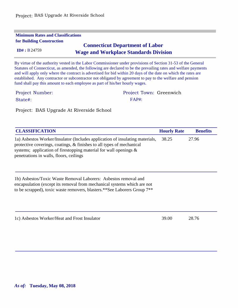
By virtue of the authority vested in the Labor Commissioner under provisions of Section 31-53 of the General Statutes of Connecticut, as amended, the following are declared to be the prevailing rates and welfare payments and will apply only where the contract is advertised for bid within 20 days of the date on which the rates are established. Any contractor or subcontractor not obligated by agreement to pay to the welfare and pension fund shall pay this amount to each employee as part of his/her hourly wages.
Minimum Rates and Classifications for Building Construction
Connecticut Department of LaborWage and Workplace Standards Division
Number: Town:
B 24759
State#: FAP#:
ID# :
Hourly Rate BenefitsCLASSIFICATION
38.25 27.961a) Asbestos Worker/Insulator (Includes application of insulating materials, protective coverings, coatings, & finishes to all types of mechanical systems; application of firestopping material for wall openings & penetrations in walls, floors, ceilings
1b) Asbestos/Toxic Waste Removal Laborers: Asbestos removal and encapsulation (except its removal from mechanical systems which are not to be scrapped), toxic waste removers, blasters.**See Laborers Group 7**
39.00 28.761c) Asbestos Worker/Heat and Frost Insulator
Tuesday, May 08, 2018As of:

Project: BAS Upgrade At Riverside School
38.34 26.012) Boilermaker
33.48 33.09 + a3a) Bricklayer, Cement Mason, Concrete Finisher (including caulking), Stone Masons
34.90 25.873b) Tile Setter
31.69 22.353c) Terrazzo Mechanics and Marble Setters
26.70 21.753d) Tile, Marble & Terrazzo Finishers
33.48 32.063e) Plasterer
Tuesday, May 08, 2018As of:

Project: BAS Upgrade At Riverside School
------LABORERS------
30.05 20.104) Group 1: Laborers (common or general), acetylene burners, carpenter tenders, concrete specialists, wrecking laborers, fire watchers.
30.30 20.104a) Group 2: Mortar mixers, plaster tender, power buggy operators, powdermen, fireproofer/mixer/nozzleman (Person running mixer and spraying fireproof only).
30.55 20.104b) Group 3: Jackhammer operators/pavement breaker, mason tender (brick), mason tender (cement/concrete), forklift operators and forklift operators (masonry).
30.55 20.104c) **Group 4: Pipelayers (Installation of water, storm drainage or sewage lines outside of the building line with P6, P7 license) (the pipelayer rate shall apply only to one or two employees of the total crew who primary task is to actually perform the mating of pipe sections) P6 and P7 rate is $26.80.
30.55 20.104d) Group 5: Air track operator, sand blaster and hydraulic drills.
Tuesday, May 08, 2018As of:
Project: BAS Upgrade At Riverside School
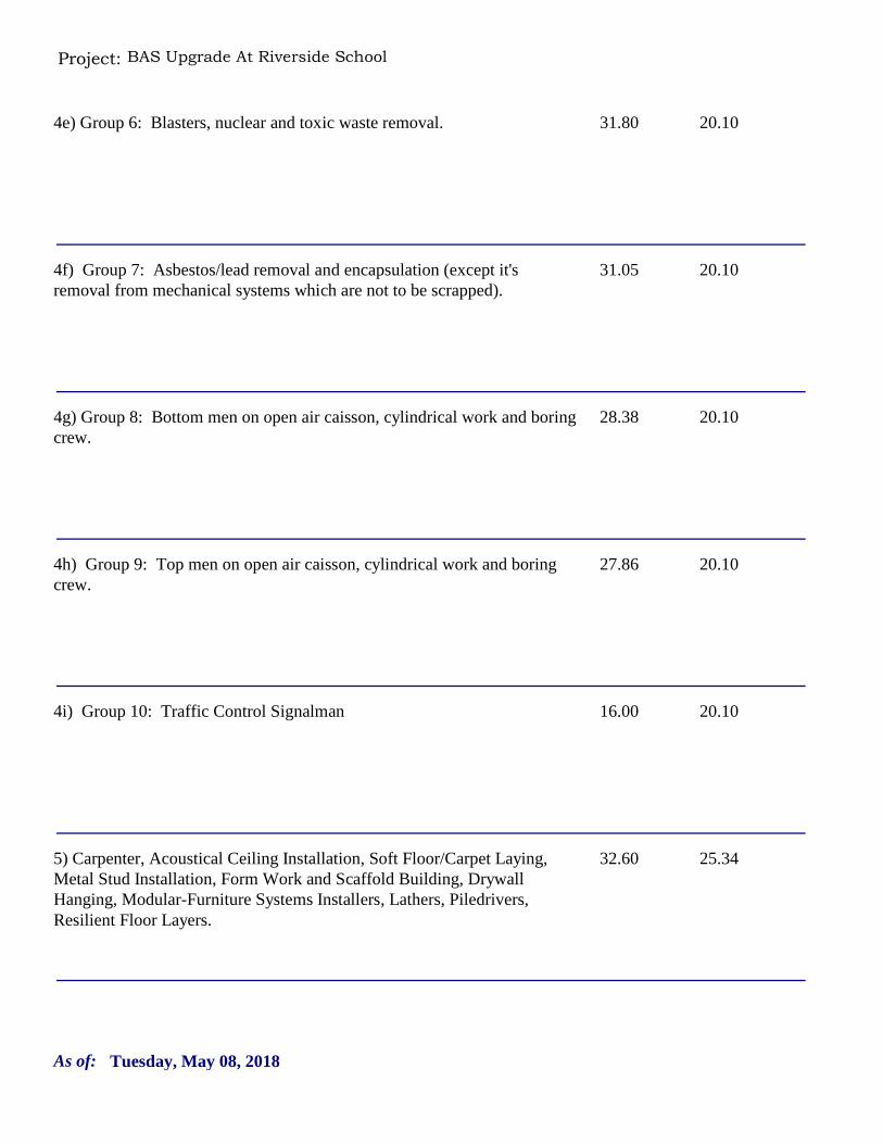
31.80 20.104e) Group 6: Blasters, nuclear and toxic waste removal.
31.05 20.104f) Group 7: Asbestos/lead removal and encapsulation (except it's removal from mechanical systems which are not to be scrapped).
28.38 20.104g) Group 8: Bottom men on open air caisson, cylindrical work and boring crew.
27.86 20.104h) Group 9: Top men on open air caisson, cylindrical work and boring crew.
16.00 20.104i) Group 10: Traffic Control Signalman
32.60 25.345) Carpenter, Acoustical Ceiling Installation, Soft Floor/Carpet Laying, Metal Stud Installation, Form Work and Scaffold Building, Drywall Hanging, Modular-Furniture Systems Installers, Lathers, Piledrivers, Resilient Floor Layers.
Tuesday, May 08, 2018As of:

Project: BAS Upgrade At Riverside School
33.14 25.745a) Millwrights
34.50 29.646) Electrical Worker (including low voltage wiring) (Trade License required: E1,2 L-5,6 C-5,6 T-1,2 L-1,2 V-1,2,7,8,9)
51.71 32.645+a+b7a) Elevator Mechanic (Trade License required: R-1,2,5,6)
-----LINE CONSTRUCTION----
26.50 6.5% + 9.00Groundman
48.19 6.5% + 22.00Linemen/Cable Splicer
Tuesday, May 08, 2018As of:
Project: BAS Upgrade At Riverside School
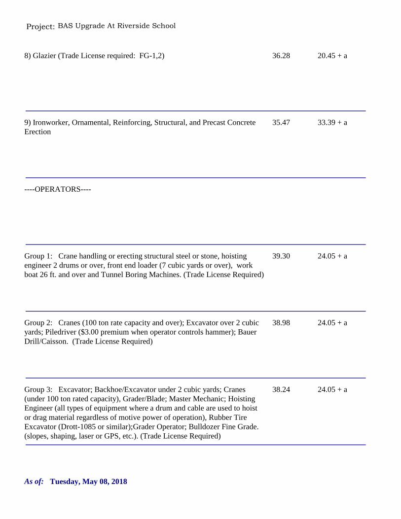
36.28 20.45 + a8) Glazier (Trade License required: FG-1,2)
35.47 33.39 + a9) Ironworker, Ornamental, Reinforcing, Structural, and Precast Concrete Erection
----OPERATORS----
39.30 24.05 + aGroup 1: Crane handling or erecting structural steel or stone, hoisting engineer 2 drums or over, front end loader (7 cubic yards or over), work boat 26 ft. and over and Tunnel Boring Machines. (Trade License Required)
38.98 24.05 + aGroup 2: Cranes (100 ton rate capacity and over); Excavator over 2 cubic yards; Piledriver ($3.00 premium when operator controls hammer); Bauer Drill/Caisson. (Trade License Required)
38.24 24.05 + aGroup 3: Excavator; Backhoe/Excavator under 2 cubic yards; Cranes (under 100 ton rated capacity), Grader/Blade; Master Mechanic; Hoisting Engineer (all types of equipment where a drum and cable are used to hoist or drag material regardless of motive power of operation), Rubber Tire Excavator (Drott-1085 or similar);Grader Operator; Bulldozer Fine Grade. (slopes, shaping, laser or GPS, etc.). (Trade License Required)
Tuesday, May 08, 2018As of:
Project: BAS Upgrade At Riverside School
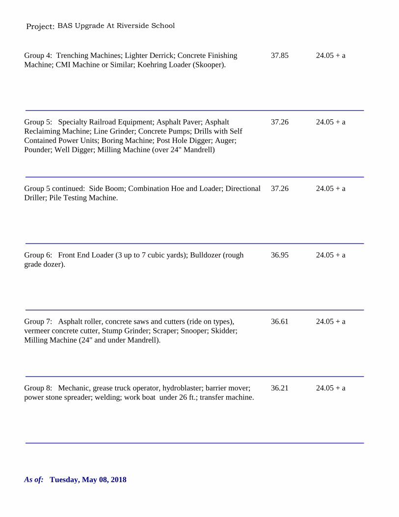
37.85 24.05 + aGroup 4: Trenching Machines; Lighter Derrick; Concrete Finishing Machine; CMI Machine or Similar; Koehring Loader (Skooper).
37.26 24.05 + aGroup 5: Specialty Railroad Equipment; Asphalt Paver; Asphalt Reclaiming Machine; Line Grinder; Concrete Pumps; Drills with Self Contained Power Units; Boring Machine; Post Hole Digger; Auger; Pounder; Well Digger; Milling Machine (over 24" Mandrell)
37.26 24.05 + aGroup 5 continued: Side Boom; Combination Hoe and Loader; Directional Driller; Pile Testing Machine.
36.95 24.05 + aGroup 6: Front End Loader (3 up to 7 cubic yards); Bulldozer (rough grade dozer).
36.61 24.05 + aGroup 7: Asphalt roller, concrete saws and cutters (ride on types), vermeer concrete cutter, Stump Grinder; Scraper; Snooper; Skidder; Milling Machine (24" and under Mandrell).
36.21 24.05 + aGroup 8: Mechanic, grease truck operator, hydroblaster; barrier mover; power stone spreader; welding; work boat under 26 ft.; transfer machine.
Tuesday, May 08, 2018As of:

Project: BAS Upgrade At Riverside School
35.78 24.05 + aGroup 9: Front end loader (under 3 cubic yards), skid steer loader regardless of attachments, (Bobcat or Similar): forklift, power chipper; landscape equipment (including Hydroseeder).
33.74 24.05 + aGroup 10: Vibratory hammer; ice machine; diesel and air, hammer, etc.
33.74 24.05 + aGroup 11: Conveyor, earth roller, power pavement breaker (whiphammer), robot demolition equipment.
33.68 24.05 + aGroup 12: Wellpoint operator.
33.10 24.05 + aGroup 13: Compressor battery operator.
31.96 24.05 + aGroup 14: Elevator operator; tow motor operator (solid tire no rough terrain).
Tuesday, May 08, 2018As of:

Project: BAS Upgrade At Riverside School
31.55 24.05 + aGroup 15: Generator Operator; Compressor Operator; Pump Operator; Welding Machine Operator; Heater Operator.
30.90 24.05 + aGroup 16: Maintenance Engineer/Oiler.
35.21 24.05 + aGroup 17: Portable asphalt plant operator; portable crusher plant operator; portable concrete plant operator.
32.79 24.05 + aGroup 18: Power safety boat; vacuum truck; zim mixer; sweeper; (Minimum for any job requiring a CDL license).
------PAINTERS (Including Drywall Finishing)------
32.72 20.4510a) Brush and Roller
Tuesday, May 08, 2018As of:
Project: BAS Upgrade At Riverside School
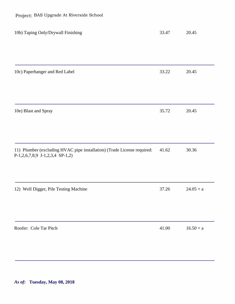
33.47 20.4510b) Taping Only/Drywall Finishing
33.22 20.4510c) Paperhanger and Red Label
35.72 20.4510e) Blast and Spray
41.62 30.3611) Plumber (excluding HVAC pipe installation) (Trade License required: P-1,2,6,7,8,9 J-1,2,3,4 SP-1,2)
37.26 24.05 + a12) Well Digger, Pile Testing Machine
41.00 16.50 + aRoofer: Cole Tar Pitch
Tuesday, May 08, 2018As of:
Project: BAS Upgrade At Riverside School
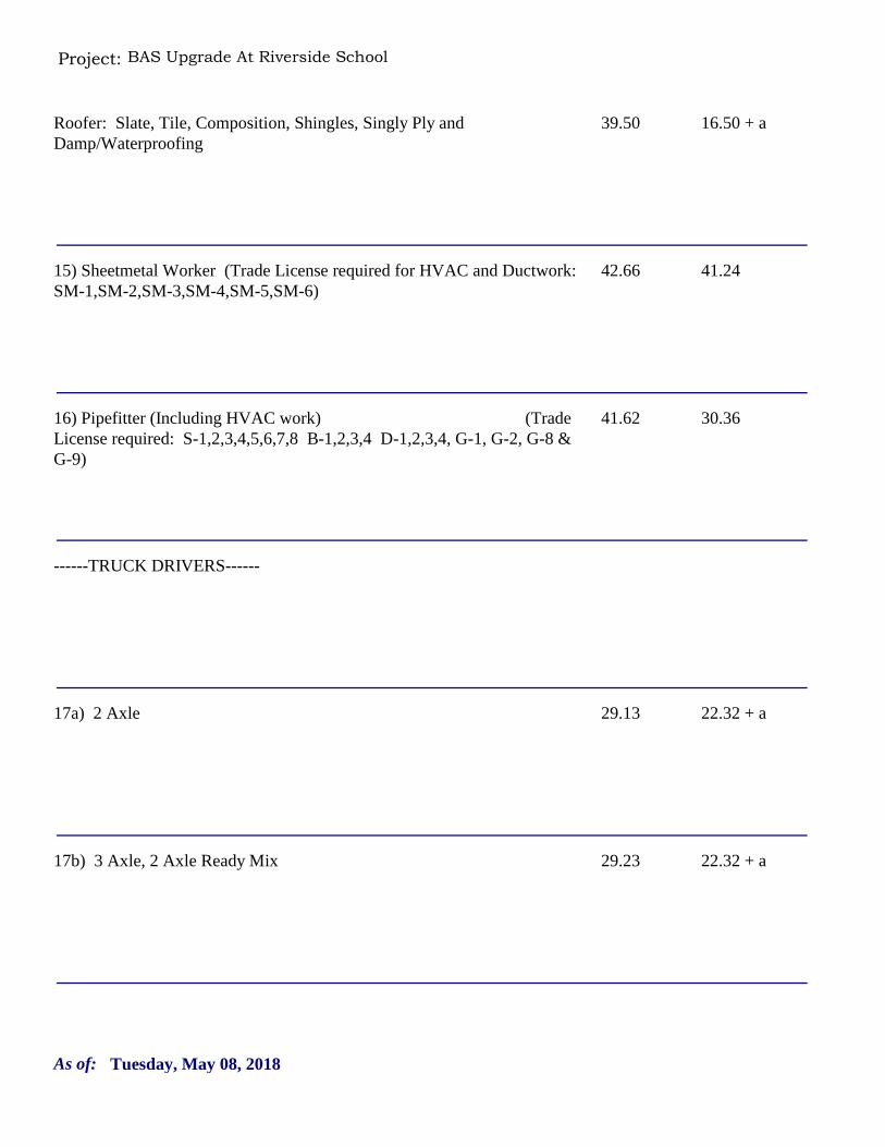
39.50 16.50 + aRoofer: Slate, Tile, Composition, Shingles, Singly Ply and Damp/Waterproofing
42.66 41.2415) Sheetmetal Worker (Trade License required for HVAC and Ductwork: SM-1,SM-2,SM-3,SM-4,SM-5,SM-6)
41.62 30.3616) Pipefitter (Including HVAC work) (Trade License required: S-1,2,3,4,5,6,7,8 B-1,2,3,4 D-1,2,3,4, G-1, G-2, G-8 & G-9)
------TRUCK DRIVERS------
29.13 22.32 + a17a) 2 Axle
29.23 22.32 + a17b) 3 Axle, 2 Axle Ready Mix
Tuesday, May 08, 2018As of:

Project: BAS Upgrade At Riverside School
29.28 22.32 + a17c) 3 Axle Ready Mix
29.33 22.32 + a17d) 4 Axle, Heavy Duty Trailer up to 40 tons
29.38 22.32 + a17e) 4 Axle Ready Mix
29.58 22.32 + a17f) Heavy Duty Trailer (40 Tons and Over)
29.38 22.32 + a17g) Specialized Earth Moving Equipment (Other Than Conventional Type on-the-Road Trucks and Semi-Trailers, Including Euclids)
43.92 15.84 + a18) Sprinkler Fitter (Trade License required: F-1,2,3,4)
Tuesday, May 08, 2018As of:

Project: BAS Upgrade At Riverside School
25.76 7.3419) Theatrical Stage Journeyman
Tuesday, May 08, 2018As of:
Project: BAS Upgrade At Riverside School
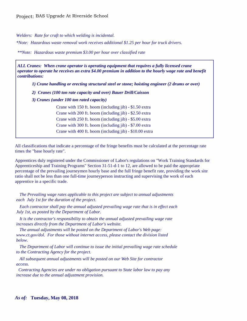
Welders: Rate for craft to which welding is incidental.
*Note: Hazardous waste removal work receives additional $1.25 per hour for truck drivers.
**Note: Hazardous waste premium $3.00 per hour over classified rate
Crane with 150 ft. boom (including jib) - $1.50 extraCrane with 200 ft. boom (including jib) - $2.50 extraCrane with 250 ft. boom (including jib) - $5.00 extraCrane with 300 ft. boom (including jib) - $7.00 extra
All classifications that indicate a percentage of the fringe benefits must be calculated at the percentage rate times the "base hourly rate".
Apprentices duly registered under the Commissioner of Labor's regulations on "Work Training Standards for Apprenticeship and Training Programs" Section 31-51-d-1 to 12, are allowed to be paid the appropriate percentage of the prevailing journeymen hourly base and the full fringe benefit rate, providing the work site ratio shall not be less than one full-time journeyperson instructing and supervising the work of each apprentice in a specific trade.
Crane with 400 ft. boom (including jib) - $10.00 extra
Each contractor shall pay the annual adjusted prevailing wage rate that is in effect each July 1st, as posted by the Department of Labor.
It is the contractor's responsibility to obtain the annual adjusted prevailing wage rate increases directly from the Department of Labor's website. The annual adjustments will be posted on the Department of Labor's Web page:
www.ct.gov/dol. For those without internet access, please contact the division listed below.
The Department of Labor will continue to issue the initial prevailing wage rate schedule to the Contracting Agency for the project.
All subsequent annual adjustments will be posted on our Web Site for contractor access.
The Prevailing wage rates applicable to this project are subject to annual adjustments each July 1st for the duration of the project.
Contracting Agencies are under no obligation pursuant to State labor law to pay any increase due to the annual adjustment provision.
ALL Cranes: When crane operator is operating equipment that requires a fully licensed crane operator to operate he receives an extra $4.00 premium in addition to the hourly wage rate and benefit contributions:
1) Crane handling or erecting structural steel or stone; hoisting engineer (2 drums or over)
2) Cranes (100 ton rate capacity and over) Bauer Drill/Caisson
3) Cranes (under 100 ton rated capacity)
Tuesday, May 08, 2018As of:

Project: BAS Upgrade At Riverside School
Please direct any questions which you may have pertaining to classification of work and payment of prevailing wages to the Wage and Workplace Standards Division, telephone (860)263-6790.
Effective October 1, 2005 - Public Act 05-50: any person performing the work of any mechanic, laborer, or worker shall be paid prevailing wage
All Person who perform work ON SITE must be paid prevailing wage for the appropriate mechanic, laborer, or worker classification.
All certified payrolls must list the hours worked and wages paid to All Persons who perform work ON SITE regardless of their ownership i.e.: (Owners, Corporate Officers, LLC Members, Independent Contractors, et. al)
Reporting and payment of wages is required regardless of any contractual relationship alleged to exist between the contractor and such person.
~~Unlisted classifications needed for work not included within the scope of the classifications listed may be added after award only as provided in the labor standards contract clause (29 CFR 5.5 (a) (1) (ii)).
Tuesday, May 08, 2018As of:

Greenwich Public Schools Riverside School BAS Upgrade
38
REFERENCES List at least five (5) references for similar projects in size, scope, and complexity, within Connecticut and / or New York. THIS PAGE MUST BE COMPLETED AND SUBMITTED WITH YOUR BID. 1) Client________________________________________________________________________ Project Address_______________________________________________________________ Approximate $ Value _____________ Date: Started __________ Completed _____________ Contact: Name ____________________________Telephone # _________________________ 2) Client________________________________________________________________________ Project Address_______________________________________________________________ Approximate $ Value _____________ Date: Started __________ Completed _____________ Contact: Name ____________________________Telephone # _________________________ 3) Client________________________________________________________________________ Project Address________________________________________________________________ Approximate $ Value _____________ Date: Started __________ Completed _____________ Contact: Name ____________________________Telephone # _________________________ 4) Client________________________________________________________________________ Project Address_______________________________________________________________ Approximate $ Value _____________ Date: Started __________ Completed _____________ Contact: Name ____________________________Telephone # _________________________ 5) Client________________________________________________________________________ Project Address_______________________________________________________________ Approximate $ Value _____________ Date: Started __________ Completed _____________ Contact: Name ____________________________Telephone # _________________________
Greenwich Public Schools Riverside School BAS Upgrade
39
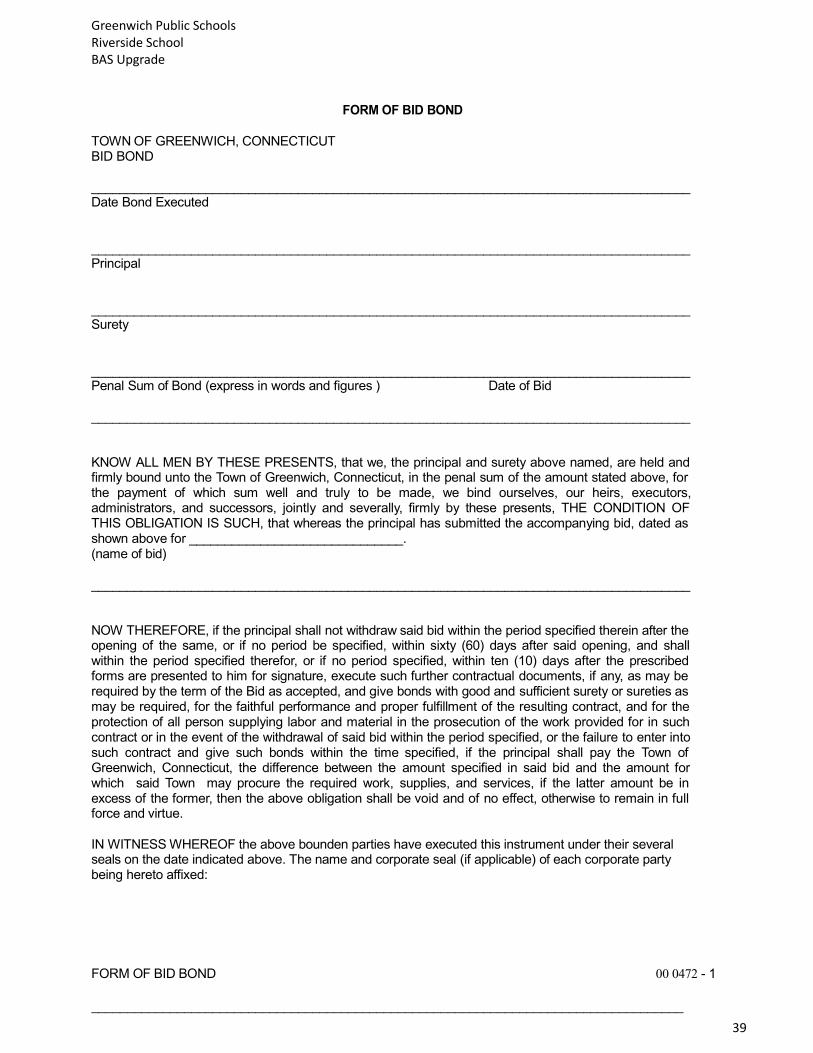
FORM OF BID BOND TOWN OF GREENWICH, CONNECTICUT BID BOND ____________________________________________________________________________________ Date Bond Executed ____________________________________________________________________________________ Principal ____________________________________________________________________________________ Surety ____________________________________________________________________________________ Penal Sum of Bond (express in words and figures ) Date of Bid ____________________________________________________________________________________ KNOW ALL MEN BY THESE PRESENTS, that we, the principal and surety above named, are held and firmly bound unto the Town of Greenwich, Connecticut, in the penal sum of the amount stated above, for the payment of which sum well and truly to be made, we bind ourselves, our heirs, executors, administrators, and successors, jointly and severally, firmly by these presents, THE CONDITION OF THIS OBLIGATION IS SUCH, that whereas the principal has submitted the accompanying bid, dated as shown above for ______________________________. (name of bid) ____________________________________________________________________________________ NOW THEREFORE, if the principal shall not withdraw said bid within the period specified therein after the opening of the same, or if no period be specified, within sixty (60) days after said opening, and shall within the period specified therefor, or if no period specified, within ten (10) days after the prescribed forms are presented to him for signature, execute such further contractual documents, if any, as may be required by the term of the Bid as accepted, and give bonds with good and sufficient surety or sureties as may be required, for the faithful performance and proper fulfillment of the resulting contract, and for the protection of all person supplying labor and material in the prosecution of the work provided for in such contract or in the event of the withdrawal of said bid within the period specified, or the failure to enter into such contract and give such bonds within the time specified, if the principal shall pay the Town of Greenwich, Connecticut, the difference between the amount specified in said bid and the amount for which said Town may procure the required work, supplies, and services, if the latter amount be in excess of the former, then the above obligation shall be void and of no effect, otherwise to remain in full force and virtue. IN WITNESS WHEREOF the above bounden parties have executed this instrument under their several seals on the date indicated above. The name and corporate seal (if applicable) of each corporate party being hereto affixed:
FORM OF BID BOND 00 0472 - 1
___________________________________________________________________________________

Greenwich Public Schools Riverside School BAS Upgrade
40
Name of Partnership _____________________________________________________________________________ (SEAL) Business Address
___________________________________________________________________________________ Partner- (Hereunto Duly Authorized) IN THE PRESENCE OF:
WITNESS INDIVIDUAL PRINCIPAL
1.__________________________________AS TO___________________ (SEAL)
2.__________________________________AS TO___________________ (SEAL) 3.__________________________________AS TO___________________ (SEAL) 4.__________________________________AS TO___________________ (SEAL) __________________________________________ CORPORATE/ LLC PRINCIPAL __________________________________________ BUSINESS ADDRESS AFFIX CORPORATE SEAL ____________________________________ WITNESS __________________________________________ BY- (HEREUNTO DULY AUTHORIZED) _________________________________________ TITLE __________________________________________ CORPORATE/ LLC PRINCIPAL __________________________________________ BUSINESS ADDRESS AFFIX CORPORATE SEAL ____________________________________ WITNESS __________________________________________ BY- (HEREUNTO DULY AUTHORIZED) _________________________________________ TITLE
Greenwich Public Schools Riverside School BAS Upgrade
41
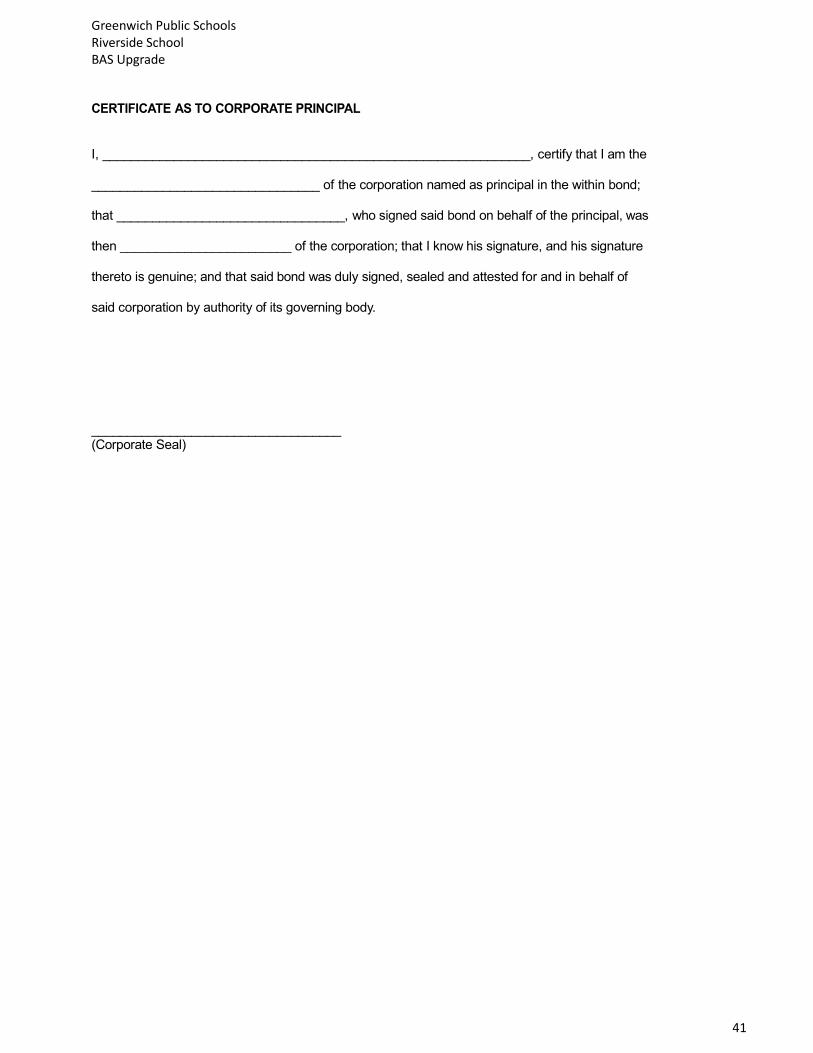
CERTIFICATE AS TO CORPORATE PRINCIPAL I, ____________________________________________________________, certify that I am the ________________________________ of the corporation named as principal in the within bond; that ________________________________, who signed said bond on behalf of the principal, was then ________________________ of the corporation; that I know his signature, and his signature thereto is genuine; and that said bond was duly signed, sealed and attested for and in behalf of said corporation by authority of its governing body.
___________________________________ (Corporate Seal)

Greenwich Public Schools Riverside School BAS Upgrade
42
PERFORMANCE, MAINTENANCE AND PAYMENT BOND BOND NO. _______________________ CONTRACT NO. _______________________________ KNOW ALL MEN BY THESE PRESENTS. That we ___________________________________________ _____________________________________, as Principal, and ________________________________ a corporation organized under the laws of the State of_________________________ and authorized to do business in the State of Connecticut as Surety, for holden and firmly bound jointly and severally unto the Town of Greenwich, Connecticut, herein referred to as the Town, the territorial corporation located in the County of Fairfield, in the penal sum of _________________________________________________________ Dollars ($__________________), to be paid to it or its certain attorney, successors or assigns, to which payment well and truly to be made, we the said Obligors do bind ourselves, and each of us, our heirs, executors, administrators, and successors firmly by these presents. IN WITNESS WHEREOF we have hereunto set for cause to be set our respective hands, names and seals this ___________________________ day of __________________________, 20___ The condition of this obligation is such, that whereas the above named Principal has entered into a certain written contract with the Town of Greenwich, Connecticut, dated the ___________________________ day of __________________________, 20___ NOW, THEREFORE, if the said Principal shall well and faithfully perform said contract according to its provisions, and fully indemnify and save harmless the Town from all costs and damages which the Town may suffer by reason of failure so to do, and shall pay for all equipment, appurtenances, materials and labor furnished, used or employed in the execution of said contract, and shall indemnify and save harmless the Town from all suits or claims of any nature or description against the Town by reason of any injuries or damages sustained by any person or persons on account of any act or omission of said Principal, his servants or agents, or his subcontractors in the construction of the work or in guarding the work, or on account of the use of faulty or improper materials, or by reason of claims under the Workmen’s Compensation Laws or other laws by any employee of the Principal or his subcontractors, or by reason of the use of patented material, machinery, device, equipment, process, method of construction or design in any way involved in the work, and shall indemnify the Town against such defective workmanship, material and equipment as may be discovered within one (1) year after completion and final acceptance of the work, and shall make good in such defective workmanship and material as may be discovered within said period of one (1) year, then the obligation shall be void, otherwise to remain in full force and effect. The Surety hereby stipulates and agrees that any modifications, omissions or additions in or to the terms of the aforesaid contract, or in or to the plans or specifications therefor, or any extension of time, shall in no wise affect the obligation of the Surety under this bond, the surety hereby waiving any and all right to any notice of any such modifications, omissions, changes, additions or extensions. Contractor Name:___________________________________ By:_____________________________________ Surety Name:______________________________________ By:_____________________________________

Greenwich Public Schools Riverside School BAS Upgrade
43
INSURANCE PROCEDURE
PLEASE NOTE:
THIS PAGE MUST BE RETURNED WITH YOUR BIDIRFP. FAILURE TO DO SO MAY RESULT IN YOUR
BID/RFP BEING REJECTED.
Please take the insurance requirements of the Contract to your agent/broker immediately upon receipt of the bid
documents to determine your existing coverage and any costs for new or additional coverage required for the
work noted in this Request for BID/RFP. Any BID/RFP with deficient insurance requirements will be rejected.
STATEMENT OF VENDOR:
I have read the insurance requirements for this work and have taken the documentation to my insurance
agent/broker. The BID/RFP cost reflects any additional costs relating to insurance requirements for this work.
Signature Date
Greenwich Public Schools Riverside School BAS Upgrade
44
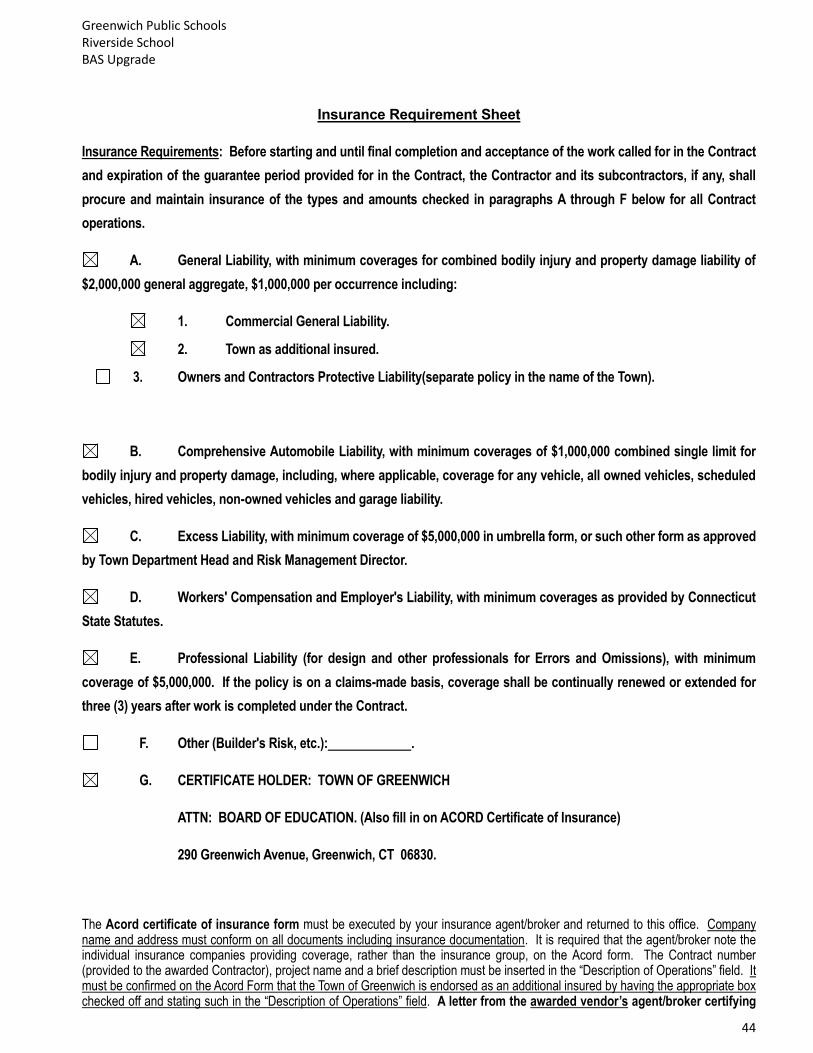
Insurance Requirement Sheet
Insurance Requirements: Before starting and until final completion and acceptance of the work called for in the Contract
and expiration of the guarantee period provided for in the Contract, the Contractor and its subcontractors, if any, shall
procure and maintain insurance of the types and amounts checked in paragraphs A through F below for all Contract
operations.
A. General Liability, with minimum coverages for combined bodily injury and property damage liability of
$2,000,000 general aggregate, $1,000,000 per occurrence including:
1. Commercial General Liability.
2. Town as additional insured.
3. Owners and Contractors Protective Liability(separate policy in the name of the Town).
B. Comprehensive Automobile Liability, with minimum coverages of $1,000,000 combined single limit for
bodily injury and property damage, including, where applicable, coverage for any vehicle, all owned vehicles, scheduled
vehicles, hired vehicles, non-owned vehicles and garage liability.
C. Excess Liability, with minimum coverage of $5,000,000 in umbrella form, or such other form as approved
by Town Department Head and Risk Management Director.
D. Workers' Compensation and Employer's Liability, with minimum coverages as provided by Connecticut
State Statutes.
E. Professional Liability (for design and other professionals for Errors and Omissions), with minimum
coverage of $5,000,000. If the policy is on a claims-made basis, coverage shall be continually renewed or extended for
three (3) years after work is completed under the Contract.
F. Other (Builder's Risk, etc.): .
G. CERTIFICATE HOLDER: TOWN OF GREENWICH
ATTN: BOARD OF EDUCATION. (Also fill in on ACORD Certificate of Insurance)
290 Greenwich Avenue, Greenwich, CT 06830.
The Acord certificate of insurance form must be executed by your insurance agent/broker and returned to this office. Company name and address must conform on all documents including insurance documentation. It is required that the agent/broker note the individual insurance companies providing coverage, rather than the insurance group, on the Acord form. The Contract number (provided to the awarded Contractor), project name and a brief description must be inserted in the “Description of Operations” field. It must be confirmed on the Acord Form that the Town of Greenwich is endorsed as an additional insured by having the appropriate box checked off and stating such in the “Description of Operations” field. A letter from the awarded vendor’s agent/broker certifying
Greenwich Public Schools Riverside School BAS Upgrade
45
that the Town of Greenwich has been endorsed onto the general liability policy as an additional insured is also mandatory. This letter must follow exactly the format provided by the Purchasing Department and must be signed by the same individual authorized representative who signed the Acord form. If the insurance coverage required is provided on more than one Acord certificate of insurance, then additional endorsement letters are also required. Contract development will begin upon receipt of complete, correct insurance documentation.
The Contractor shall be responsible for maintaining the above insurance coverages in force to secure all of the Contractor's obligations under the Contract with an insurance company or companies with an AM Best Rating of B+:VII or better, licensed to write such insurance in Connecticut and acceptable to the Risk Manager, Town of Greenwich. For excess liability only, non-admitted insurers are acceptable, provided they are permitted to do business through Connecticut excess line brokers per listing on the current list of Licensed Insurance Companies, Approved Reinsurers, Surplus Lines Insurers and Risk Retention Groups issued by the State of Connecticut Insurance Department.

Greenwich Public Schools Riverside School BAS Upgrade
46
(SAMPLE ENDORSEMENT LETTER)
AGENT/BROKER
(LETTERHEAD)
(Date)
Eugene H. Watts, Senior Buyer
Purchasing Department
Town of Greenwich/Board of Education
290 Greenwich Avenue – Havemeyer Building
Greenwich, CT 06830
Re:
Town of Greenwich/Board of Education / Contract #
Dear Mr. Watts:
The undersigned hereby certifies as follows:
(1) I am a duly licensed insurance agent under the laws of the State of [insert State] and an authorized
representative of all companies affording coverage under the Acord form submitted herewith;
(2) The Town of Greenwich has been endorsed as an additional insured under the general liability policy no.
[insert policy number], issued by [insert company affording coverage] to [name of insured];
(3) The general liability policy referenced in paragraph (2) above meets or exceeds the coverage in
Commercial General Liability ISO form CG 00 01 10 01, including contractual liability;
(4) The policies listed in the Acord form submitted to the Town of Greenwich in connection with the above-
referenced contract have been issued to the insured in the amounts stated and for the periods indicated in
the Acord form; and
(5) The Town of Greenwich shall be given thirty (30) days prior written notice of cancellation, lapse or
restrictive amendment (except ten days notice of nonpayment) of the policies listed in the Acord form.
Sincerely,
Authorized Representative for all companies listed in the Acord form
Greenwich Public Schools Riverside School BAS Upgrade
47
A.M. BEST KEY RATING GUIDE FORM The following insurance companies are licensed in the State of Connecticut per the 2011 edition of the A.M. Best Key Rating Guide For Property and Casualty, 1. Company Name: __________________________________ a) Page Number: _____________ b) Rating is: _____________ 2. Company Name: __________________________________ a) Page Number: _____________ b) Rating is: _____________ 3. Company Name: __________________________________ a) Page Number: _____________ b) Rating is: _____________ 4. Company Name: __________________________________ a) Page Number: _____________ b) Rating is: _____________ 5. Company Name: __________________________________ a) Page Number: _____________ b) Rating is: _____________ 6. Company Name: __________________________________ a) Page Number: _____________ b) Rating is: _____________
Greenwich Public Schools Riverside School BAS Upgrade
48
AFFIRMATIVE ACTION COMPLIANCE AFFIDAVIT
COMMISSION ON HUMAN RIGHTS AND OPPORTUNITIES CONTRACT COMPLIANCE REGULATIONS NOTIFICATION TO BIDDERS AFFIRMATIVE ACTION COMPLIANCE AFFIDAVIT The contract to be awarded is subject to contract compliance requirements mandated by Sections 4a-60 and 4a-60a of the Connecticut General Statutes; and, when the awarding agency is the State, Sections 46a-71(d) and 46a-81i(d) of the Connecticut General Statutes. There are Contract Compliance Regulations codified at Section 46a-68j-21 through 43 of the Regulations of Connecticut State Agencies, which establish a procedure for awarding all contracts covered by Sections 4a-60 and 46a-71(d) of the Connecticut General Statutes. According to Section 46a-68j-30(9) of the Contract Compliance Regulations, every agency awarding a contract subject to the contract compliance requirements has an obligation to “aggressively solicit the participation of legitimate minority business enterprises as bidders, contractors, subcontractors and suppliers of materials.” “Minority business enterprise” is defined in Section 4a-60 of the Connecticut General Statutes as a business wherein fifty-one percent or more of the capital stock, or assets belong to a person or persons: “(1) Who are active in daily affairs of the enterprise; (2) who have the power to direct the management and policies of the enterprise; and (3) who are members of a minority, as such term is defined in subsection (a) of Section 32-9n.” “Minority” groups are defined in Section 32-9n of the Connecticut General Statutes as “(1) Black Americans . . .(2) Hispanic Americans . . . (3) persons who have origins in the Iberian Peninsula . . . (4)Women . . . (5) Asian Pacific Americans and Pacific Islanders; (6) American Indians . . .” An individual with a disability is also a minority business enterprise as provided by Section 4a-60g of the Connecticut General Statutes. The above definitions apply to the contract compliance requirements by virtue of Section 46a-68j-21(11) of the Contract Compliance Regulations. The awarding agency will consider the following factors when reviewing the bidder’s qualifications under the contract compliance requirements: (a) the bidder’s success in implementing an affirmative action plan;
(b) the bidder’s success in developing an apprenticeship program complying with Sections 46a-68-1 to 46a-
68-17 of the Administrative Regulations of Connecticut State Agencies, inclusive;
(c) the bidder’s promise to develop and implement a successful affirmative action plan;
(d) the bidder’s submission of employment statistics contained in the “Employment Information Form”,
indicating that the composition of its workforce is at or near parity when compared to the racial and sexual composition of the workforce in the relevant labor market area; and
(e)the bidder’s promise to set aside a portion of the contract for legitimate minority business enterprises.
See Section 46a-68j-30(10)(E) of the Contract Compliance Regulations.
*INSTRUCTIONS: Bidders must sign acknowledgement below and return acknowledgement to
Awarding Agency along with bid proposal. The undersigned acknowledges receiving and reading a copy of the “Notification to Bidders” form.
________________________________ ___________________________
Signature Date

Greenwich Public Schools Riverside School BAS Upgrade
49
On behalf of: ___________________________________
____________________________________ ____________________________________
Greenwich Public Schools Riverside School BAS Upgrade
50
CONSENT OF SURETY The Undersigned surety, being the surety which issued bonds No._________ for the Town of Greenwich Contract No. ___________ hereby consents to release of final payment and all retainages to the contractor- principal.
(Name of Surety) By_______________________________________ Its
ACKNOWLEDGMENT
STATE OF ss: COUNTY OF
This is to certify the above signatory who executed this instrument was either known to me or satisfactorily proven to me to be the person whom he purports to be.
______________________________________ Notary Public

Greenwich Public Schools Riverside School BAS Upgrade
51
AFFIDAVIT FOR FINAL PAYMENT
The undersigned, being duly sworn, deposes and says:
1. That he is the ___________________________________________ of the contractor in
(Title)
the project hereinafter referred to and is authorized to execute this affidavit on behalf of the
contractor;
2. In connection with Contract # for __________________________________________
(Project Title)
it is represented that all payrolls, bills for services, materials, supplies, equipment and other
indebtedness have been paid or otherwise satisfied and that there are no outstanding claims against
the undersigned by any sub-contractor or material supplier, or no outstanding claims or intent to
file a claim against the Town of Greenwich;
. This Affidavit is made at the request of the Town of Greenwich for the purpose of inducing
final payment and knowing that it will rely upon the truth of the representation herein made.
____________________________________
(Authorized signature)
____________________________________
(Type or print name of authorized person)
Subscribed and sworn to before me, a Notary
Public, in and for the County of ____________________
and State of ________________________, this ___________day
of ____________________, 2018
________________________________
Notary Public

Greenwich Public Schools Riverside School BAS Upgrade
52
ACORD CERTIFICATE OF LIABILITY INSURANCE
PRODUCER
THIS CERTIFICATE IS ISSUED AS A MATTER OF INFORMATION ONLY AND CONFERS
NO RIGHTS UPON THE CERTIFICATE HOLDER, THIS CERTIFICATE DOES NOT AMEND,
EXTEND OR ALTER THE COVERAGE AFFORDED BY THE POLICIES BELOW.
INSUREERS AFFORDING COVERAGE
INSURED
INSURER A:
INSURER B:
INSURER C:
INSURER D:
INSURER E:
COVERAGES
THE POLICIES OF INSURANCE LISTED BELOW HAVE BEEN ISSUED TO THE INSURED NAMED ABOVE FOR THE POLICY PERIOD INDICATED, NOTWITHSTANDING ANY REQUIREMENT, TERM OF CONDITION OF ANY CONTRACT OR OTHER DOCUMENT WITH RESPECT TO WHICH THIS CERTIFICATE MAY BE ISSUED OR MAY PERTAIN, THE INSURANCE AFFORDED BY THE POLICIES DESCRIBED HEREIN IS SUBJECT TO ALL THE TERMS, EXCLUSIONS AND CONDITIONS OF SUCH POLICIES. LIMITS SHOWN MAY HAVE BEEN REDUCED BY PAID CLAIMS. INSR LTR
TYPE OF INSURANCE POLICY NUMBER POLICY EFFECTIVE DATE(MM/DD/YY)
POLICY EXPIRATION DATE(MM/DD/YY)
LIMITS
GENERAL LIABILITY EACH OCCURENCE
COMMERCIAL GENERAL LIABILITY FIRE DAMAGE (Any one fire)
CLAIMS MADE OCCUR MED EXP (Any one person)
_______________________________________________________
PERSONAL & ADV INJURY
_______________________________________________________
GENERAL AGGRREGATE
GENERAL AGGREGATE LIMIT APPLIES PER:
PRODUCTS-COMP/OP AGG
POLICY PROJECT LOC
AUTOMOBILE LIABILITY COMBINED SINGLE LIMIT
ANY AUTO (Ea accident)
ALL OWNED AUTOS BODILY INJURY
SCHEDULED AUTOS (Per person)
HIRED AUTOS BODILY INJURY
NON-OWNED AUTOS (Per accident)
____________________________
PROPERTY DAMAGE
(Per accident)
GARAGE LIABILITY AUTO ONLY-EA ACCIDENT
ANY AUTO OTHER THAN EA ACC
AUTO ONLY: AGG
EXCESS LIABILITY EACH OCCURRENCE
OCCUR CLAIMS MADE AGGREGATE
DEDUCTIBLE
RETENTION $
WORKERS COMPENSATION AND EMPLOYERS’ LIABILITY
WC STATU- ORY LIMITS
OTH- ER
E.L. EACH ACCIDENT
E.L. DISEASE-EA EMPLOYEE
E.L. DISEASE – POLICY LIMIT
Professional Liability

Greenwich Public Schools Riverside School BAS Upgrade
53
DESCRIPTION OF OPERATIONS/LOCATIONS/VEHICLES/EXCLUSIONS ADDED BY ENDORSEMENT/SPECIAL PROVISIONS
The Town of Greenwich/Greenwich Public Schools, and Landmark Facilities Group, Inc. are listed as additional insured for contract no.
CERTIFICATE HOLDER X ADDITIONAL INSURED; INSURER LETTER: __ CANCELLATION
Certificate Holder:
Town of Greenwich
Board of Education
290 Greenwich Avenue
Greenwich, CT 06830
SHOULD ANY OF THE ABOVE DESCRIBED POLICIES BE CANCELLED BEFORE THE
EXPIRATION DATE THEREOF, THE ISSUING COMPANY WILL ENDEAVOR TO MAIL 30
DAYS WRITTEN NOTICE TO THE CERTIFICATE HOLDER NAMED TO THE LEFT, BUT FAILURE TO DO SO SHALL IMPOSE NO OBLIGATION OR LIABILITY OF ANY KIND UPON THE INSURER, ITS AGENTS OF REPRESENTATIONS
AUTHORIZED REPRESENTATIVE

Greenwich Public Schools Riverside School BAS Upgrade
54
SECTION / DRAWING NO. DESCRIPTION
M-001 PROJECT COVER SHEET
M-002
M-003
M-100
M-101
M-102
MECHANICAL NOTES AND LEGEND
MECHANICAL SPECIFICATIONS
FIRST FLOOR PLAN - SOUTH
FIRST FLOOR PLAN - NORTH
SECOND FLOOR PLAN - SOUTH
M-103
M-104
M-200
M-201
M-202
SECOND FLOOR PLAN - NORTH
PARTIAL ROOF PLAN
CONTROLS DIAGRAM HOT WATER SYSTEM
CONTROLS DIAGRAM – CONDENSER WATER SYSTEM
CONTROLS DIAGRAM – ROOFTOP UNITS, EXHAUST FANS, &
DUCTLESS SPLIT SYSTEMS
SPECIFICATIONS NO. DESCRIPTION
230500
230800
BASIC MECHANICAL MATERIALS AND METHODS
COMMISSIONING OF HVAC SYSTEMS
230900 INSTRUMENTATION AND CONTROL FOR HVAC
230993
260519
260529
260533
260553
SEQUENCE OF OPERATION
LOW-VOLTAGE ELECTRICAL POWER CONDUCTORS AND CABLES
HANGERS AND SUPPORTS FOR ELECTRICAL SYSTEMS
RACEWAYS AND BOXES FOR ELECTRICAL SYSTEMS
IDENTIFICATION FOR ELECTRICAL SYSTEMS


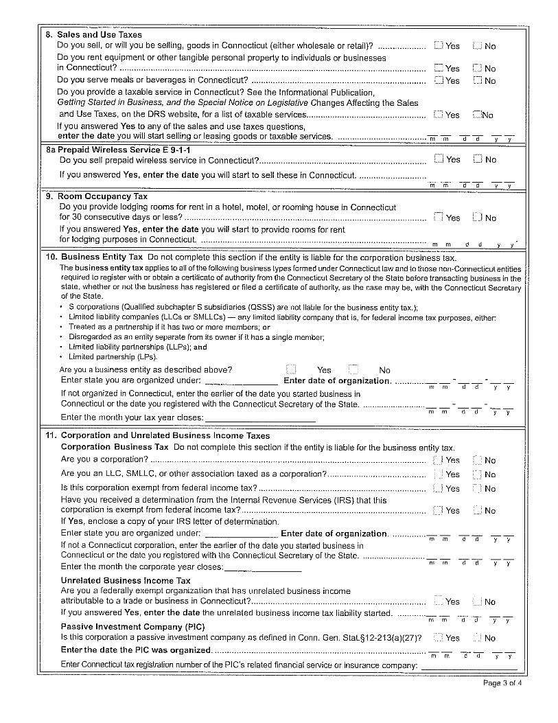

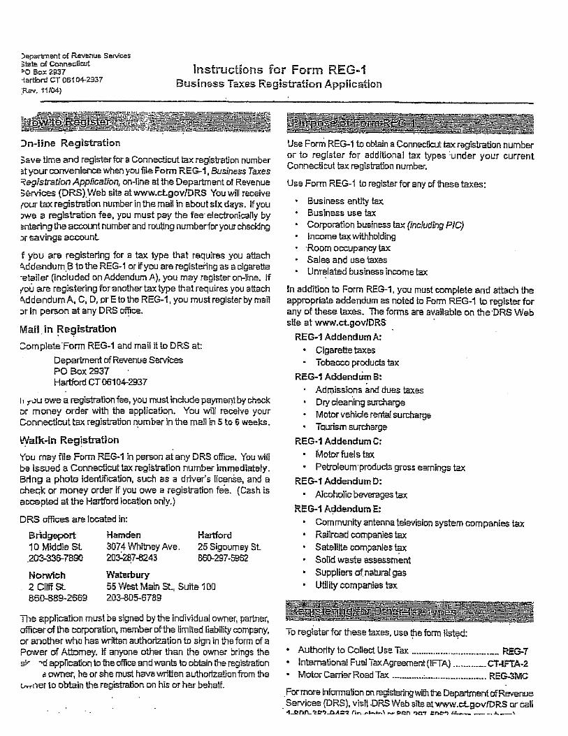


Riverside School – BAS Upgrade Landmark Facilities Group, Inc.
(BID #2205-18)
May 11, 2018 Basic Mechanical Materials and Methods
ISSUED FOR BID 230500 - 1
SECTION 230500 - BASIC MECHANICAL MATERIALS AND METHODS
PART 1 - GENERAL
1.1 RELATED DOCUMENTS
A. Drawings and general provisions of the Contract, including General and Supplementary
Conditions and Division 1 Specification Sections, apply to this Section.
1.2 SUMMARY
A. This Section includes the following:
1. Piping materials and installation instructions common to most piping systems.
2. Transition fittings.
3. Dielectric fittings.
4. Mechanical sleeve seals.
5. Sleeves.
6. Escutcheons.
7. Grout.
8. Mechanical demolition.
9. Equipment installation requirements common to equipment sections.
10. Painting and finishing.
11. Supports and anchorages.
1.3 DEFINITIONS
A. Finished Spaces: Spaces other than mechanical and electrical equipment rooms, furred spaces,
pipe and duct shafts, unheated spaces immediately below roof, spaces above ceilings,
unexcavated spaces, crawlspaces, and tunnels.
B. Exposed, Interior Installations: Exposed to view indoors. Examples include finished occupied
spaces and mechanical equipment rooms.
C. Exposed, Exterior Installations: Exposed to view outdoors or subject to outdoor ambient
temperatures and weather conditions. Examples include rooftop locations.
D. Concealed, Interior Installations: Concealed from view and protected from physical contact by
building occupants. Examples include above ceilings and in duct shafts.
E. Concealed, Exterior Installations: Concealed from view and protected from weather conditions
and physical contact by building occupants but subject to outdoor ambient temperatures.
Examples include installations within unheated shelters.
F. The following are industry abbreviations for plastic materials:
1. ABS: Acrylonitrile-butadiene-styrene plastic.

Riverside School – BAS Upgrade Landmark Facilities Group, Inc.
(BID #2205-18)
May 11, 2018 Basic Mechanical Materials and Methods
ISSUED FOR BID 230500 - 2
2. CPVC: Chlorinated polyvinyl chloride plastic.
3. PE: Polyethylene plastic.
4. PVC: Polyvinyl chloride plastic.
G. The following are industry abbreviations for rubber materials:
1. EPDM: Ethylene-propylene-diene terpolymer rubber.
2. NBR: Acrylonitrile-butadiene rubber.
1.4 SUBMITTALS
A. Product Data: For the following:
1. Transition fittings.
2. Dielectric fittings.
3. Mechanical sleeve seals.
4. Escutcheons.
B. Welding certificates.
1.5 QUALITY ASSURANCE
A. Steel Support Welding: Qualify processes and operators according to AWS D1.1, "Structural
Welding Code--Steel."
B. Steel Pipe Welding: Qualify processes and operators according to ASME Boiler and Pressure
Vessel Code: Section IX, "Welding and Brazing Qualifications."
1. Comply with provisions in ASME B31 Series, "Code for Pressure Piping."
2. Certify that each welder has passed AWS qualification tests for welding processes
involved and that certification is current.
C. Electrical Characteristics for Mechanical Equipment: Equipment of higher electrical
characteristics may be furnished provided such proposed equipment is approved in writing and
connecting electrical services, circuit breakers, and conduit sizes are appropriately modified. If
minimum energy ratings or efficiencies are specified, equipment shall comply with
requirements.
1.6 DELIVERY, STORAGE, AND HANDLING
A. Deliver pipes and tubes with factory-applied end caps. Maintain end caps through shipping,
storage, and handling to prevent pipe end damage and to prevent entrance of dirt, debris, and
moisture.
B. Store plastic pipes protected from direct sunlight. Support to prevent sagging and bending.

Riverside School – BAS Upgrade Landmark Facilities Group, Inc.
(BID #2205-18)
May 11, 2018 Basic Mechanical Materials and Methods
ISSUED FOR BID 230500 - 3
1.7 COORDINATION
A. Arrange for pipe spaces, chases, slots, and openings in building structure during progress of
construction, to allow for mechanical installations.
B. Coordinate installation of required supporting devices and set sleeves in poured-in-place
concrete and other structural components as they are constructed.
C. Coordinate requirements for access panels and doors for mechanical items requiring access that
are concealed behind finished surfaces. Access panels and doors are specified in Division 8
Section "Access Doors and Frames."
PART 2 - PRODUCTS
2.1 MANUFACTURERS
A. In other Part 2 articles where subparagraph titles below introduce lists, the following
requirements apply for product selection:
1. Available Manufacturers: Subject to compliance with requirements, manufacturers
offering products that may be incorporated into the Work include, but are not limited to,
the manufacturers specified.
2. Manufacturers: Subject to compliance with requirements, provide products by the
manufacturers specified.
2.2 PIPE, TUBE, AND FITTINGS
A. Refer to individual Division 15 piping Sections for pipe, tube, and fitting materials and joining
methods.
B. Pipe Threads: ASME B1.20.1 for factory-threaded pipe and pipe fittings.
2.3 JOINING MATERIALS
A. Refer to individual Division 15 piping Sections for special joining materials not listed below.
B. Pipe-Flange Gasket Materials: Suitable for chemical and thermal conditions of piping system
contents.
1. ASME B16.21, nonmetallic, flat, asbestos-free, 1/8-inch maximum thickness unless
thickness or specific material is indicated.
a. Full-Face Type: For flat-face, Class 125, cast-iron and cast-bronze flanges.
b. Narrow-Face Type: For raised-face, Class 250, cast-iron and steel flanges.
2. AWWA C110, rubber, flat face, 1/8 inch thick, unless otherwise indicated; and full-face
or ring type, unless otherwise indicated.
Riverside School – BAS Upgrade Landmark Facilities Group, Inc.
(BID #2205-18)
May 11, 2018 Basic Mechanical Materials and Methods
ISSUED FOR BID 230500 - 4
C. Flange Bolts and Nuts: ASME B18.2.1, carbon steel, unless otherwise indicated.
D. Plastic, Pipe-Flange Gasket, Bolts, and Nuts: Type and material recommended by piping
system manufacturer, unless otherwise indicated.
E. Solder Filler Metals: ASTM B 32, lead-free alloys. Include water-flushable flux according to
ASTM B 813.
F. Brazing Filler Metals: AWS A5.8, BCuP Series, copper-phosphorus alloys for general-duty
brazing, unless otherwise indicated; and AWS A5.8, BAg1, silver alloy for refrigerant piping,
unless otherwise indicated.
G. Welding Filler Metals: Comply with AWS D10.12 for welding materials appropriate for wall
thickness and chemical analysis of steel pipe being welded.
H. Solvent Cements for Joining Plastic Piping:
1. ABS Piping: ASTM D 2235.
2. CPVC Piping: ASTM F 493.
3. PVC Piping: ASTM D 2564. Include primer according to ASTM F 656.
4. PVC to ABS Piping Transition: ASTM D 3138.
I. Fiberglass Pipe Adhesive: As furnished or recommended by pipe manufacturer.
2.4 TRANSITION FITTINGS
A. AWWA Transition Couplings: Same size as, and with pressure rating at least equal to and with
ends compatible with, piping to be joined.
1. Accepted Manufacturers:
a. Cascade Waterworks Mfg. Co.
b. Dresser Industries, Inc.; DMD Div.
c. Ford Meter Box Company, Incorporated (The); Pipe Products Div.
d. JCM Industries.
e. Smith-Blair, Inc.
f. Viking Johnson.
2. Underground Piping NPS 1-1/2 and Smaller: Manufactured fitting or coupling.
3. Underground Piping NPS 2 and Larger: AWWA C219, metal sleeve-type coupling.
4. Aboveground Pressure Piping: Pipe fitting.
B. Plastic-to-Metal Transition Fittings: CPVC one-piece fitting with manufacturer's Schedule 80
equivalent dimensions; one end with threaded brass insert, and one solvent-cement-joint end.
1. Accepted Manufacturers:
a. Eslon Thermoplastics.

Riverside School – BAS Upgrade Landmark Facilities Group, Inc.
(BID #2205-18)
May 11, 2018 Basic Mechanical Materials and Methods
ISSUED FOR BID 230500 - 5
C. Plastic-to-Metal Transition Adaptors: One-piece fitting with manufacturer's SDR 11 equivalent
dimensions; one end with threaded brass insert, and one solvent-cement-joint end.
1. Accepted Manufacturers:
a. Thompson Plastics, Inc.
D. Plastic-to-Metal Transition Unions: MSS SP-107, CPVC four-part union. Include brass end,
solvent-cement-joint end, rubber O-ring, and union nut.
1. Accepted Manufacturers:
a. NIBCO INC.
b. NIBCO, Inc.; Chemtrol Div.
E. Flexible Transition Couplings for Underground Nonpressure Drainage Piping: ASTM C 1173
with elastomeric sleeve, ends same size as piping to be joined, and corrosion-resistant metal
band on each end.
1. Accepted Manufacturers:
a. Cascade Waterworks Mfg. Co.
b. Fernco, Inc.
c. Mission Rubber Company.
d. Plastic Oddities, Inc.
2.5 DIELECTRIC FITTINGS
A. Description: Combination fitting of copper alloy and ferrous materials with threaded, solder-
joint, plain, or weld-neck end connections that match piping system materials.
B. Insulating Material: Suitable for system fluid, pressure, and temperature.
C. Dielectric Unions: Factory-fabricated, union assembly, for 250-psig minimum working
pressure at 180 deg F.
1. Accepted Manufacturers:
a. Capitol Manufacturing Co.
b. Central Plastics Company.
c. Eclipse, Inc.
d. Epco Sales, Inc.
e. Hart Industries, International, Inc.
f. Watts Industries, Inc.; Water Products Div.
g. Zurn Industries, Inc.; Wilkins Div.
D. Dielectric Flanges: Factory-fabricated, companion-flange assembly, for 300-psig minimum
working pressure as required to suit system pressures.
1. Accepted Manufacturers:

Riverside School – BAS Upgrade Landmark Facilities Group, Inc.
(BID #2205-18)
May 11, 2018 Basic Mechanical Materials and Methods
ISSUED FOR BID 230500 - 6
a. Capitol Manufacturing Co.
b. Central Plastics Company.
c. Epco Sales, Inc.
d. Watts Industries, Inc.; Water Products Div.
E. Dielectric-Flange Kits: Companion-flange assembly for field assembly. Include flanges, full-
face- or ring-type neoprene or phenolic gasket, phenolic or polyethylene bolt sleeves, phenolic
washers, and steel backing washers.
1. Accepted Manufacturers:
a. Advance Products & Systems, Inc.
b. Calpico, Inc.
c. Central Plastics Company.
d. Pipeline Seal and Insulator, Inc.
2. Separate companion flanges and steel bolts and nuts shall have 300-psig minimum
working pressure where required to suit system pressures.
F. Dielectric Couplings: Galvanized-steel coupling with inert and noncorrosive, thermoplastic
lining; threaded ends; and 300-psig minimum working pressure at 225 deg F .
1. Accepted Manufacturers:
a. Calpico, Inc.
b. Lochinvar Corp.
G. Dielectric Nipples: Electroplated steel nipple with inert and noncorrosive, thermoplastic lining;
plain, threaded, or grooved ends; and 300-psig minimum working pressure at 225 deg F.
1. Accepted Manufacturers:
a. Perfection Corp.
b. Precision Plumbing Products, Inc.
c. Sioux Chief Manufacturing Co., Inc.
d. Victaulic Co. of America.
2.6 MECHANICAL SLEEVE SEALS
A. Description: Modular sealing element unit, designed for field assembly, to fill annular space
between pipe and sleeve.
1. Accepted Manufacturers:
a. Advance Products & Systems, Inc.
b. Calpico, Inc.
c. Metraflex Co.
d. Pipeline Seal and Insulator, Inc.
Riverside School – BAS Upgrade Landmark Facilities Group, Inc.
(BID #2205-18)
May 11, 2018 Basic Mechanical Materials and Methods
ISSUED FOR BID 230500 - 7
2. Sealing Elements: EPDM interlocking links shaped to fit surface of pipe. Include type
and number required for pipe material and size of pipe.
3. Pressure Plates: Carbon steel. Include two for each sealing element.
4. Connecting Bolts and Nuts: Carbon steel with corrosion-resistant coating of length
required to secure pressure plates to sealing elements. Include one for each sealing
element.
2.7 SLEEVES
A. Galvanized-Steel Sheet: 0.0239-inch minimum thickness; round tube closed with welded
longitudinal joint.
B. Steel Pipe: ASTM A 53, Type E, Grade B, Schedule 40, galvanized, plain ends.
C. Cast Iron: Cast or fabricated "wall pipe" equivalent to ductile-iron pressure pipe, with plain
ends and integral waterstop, unless otherwise indicated.
D. Stack Sleeve Fittings: Manufactured, cast-iron sleeve with integral clamping flange. Include
clamping ring and bolts and nuts for membrane flashing.
1. Underdeck Clamp: Clamping ring with set screws.
E. Molded PVC: Permanent, with nailing flange for attaching to wooden forms.
F. PVC Pipe: ASTM D 1785, Schedule 40.
G. Molded PE: Reusable, PE, tapered-cup shaped, and smooth-outer surface with nailing flange
for attaching to wooden forms.
2.8 ESCUTCHEONS
A. Description: Manufactured wall and ceiling escutcheons and floor plates, with an ID to closely
fit around pipe, tube, and insulation of insulated piping and an OD that completely covers
opening.
B. One-Piece, Deep-Pattern Type: Deep-drawn, box-shaped brass with polished chrome-plated
finish.
C. One-Piece, Cast-Brass Type: With set screw.
1. Finish: Polished chrome-plated and rough brass.
D. Split-Casting, Cast-Brass Type: With concealed hinge and set screw.
1. Finish: Polished chrome-plated.
E. One-Piece, Stamped-Steel Type: With set screw and chrome-plated finish.
F. Split-Plate, Stamped-Steel Type: With concealed hinge, set screw, and chrome-plated finish.

Riverside School – BAS Upgrade Landmark Facilities Group, Inc.
(BID #2205-18)
May 11, 2018 Basic Mechanical Materials and Methods
ISSUED FOR BID 230500 - 8
G. One-Piece, Floor-Plate Type: Cast-iron floor plate.
H. Split-Casting, Floor-Plate Type: Cast brass with concealed hinge and set screw.
2.9 GROUT
A. Description: ASTM C 1107, Grade B, nonshrink and nonmetallic, dry hydraulic-cement grout.
1. Characteristics: Post-hardening, volume-adjusting, nonstaining, noncorrosive,
nongaseous, and recommended for interior and exterior applications.
2. Design Mix: 5000-psi, 28-day compressive strength.
3. Packaging: Premixed and factory packaged.
PART 3 - EXECUTION
3.1 MECHANICAL DEMOLITION
A. Refer to Division 1 Sections "Cutting and Patching" and "Selective Demolition" for general
demolition requirements and procedures.
B. Disconnect, demolish, and remove mechanical systems, equipment, and components indicated
to be removed.
1. Piping to Be Removed: Remove portion of piping indicated to be removed and cap or
plug remaining piping with same or compatible piping material.
2. Piping to Be Abandoned in Place: Drain piping and cap or plug piping with same or
compatible piping material.
3. Ducts to Be Removed: Remove portion of ducts indicated to be removed and plug
remaining ducts with same or compatible ductwork material.
4. Ducts to Be Abandoned in Place: Cap or plug ducts with same or compatible ductwork
material.
5. Equipment to Be Removed: Disconnect and cap services and remove equipment.
6. Equipment to Be Removed and Reinstalled: Disconnect and cap services and remove,
clean, and store equipment; when appropriate, reinstall, reconnect, and make equipment
operational.
7. Equipment to Be Removed and Salvaged: Disconnect and cap services and remove
equipment and deliver to Owner.
C. If pipe, insulation, or equipment to remain is damaged in appearance or is unserviceable,
remove damaged or unserviceable portions and replace with new products of equal capacity and
quality.
3.2 PIPING SYSTEMS - COMMON REQUIREMENTS
A. Install piping according to the following requirements and Division 15 Sections specifying
piping systems.

Riverside School – BAS Upgrade Landmark Facilities Group, Inc.
(BID #2205-18)
May 11, 2018 Basic Mechanical Materials and Methods
ISSUED FOR BID 230500 - 9
B. Drawing plans, schematics, and diagrams indicate general location and arrangement of piping
systems. Indicated locations and arrangements were used to size pipe and calculate friction
loss, expansion, pump sizing, and other design considerations. Install piping as indicated unless
deviations to layout are approved on Coordination Drawings.
C. Install piping in concealed locations, unless otherwise indicated and except in equipment rooms
and service areas.
D. Install piping indicated to be exposed and piping in equipment rooms and service areas at right
angles or parallel to building walls. Diagonal runs are prohibited unless specifically indicated
otherwise.
E. Install piping above accessible ceilings to allow sufficient space for ceiling panel removal.
F. Install piping to permit valve servicing.
G. Install piping at indicated slopes.
H. Install piping free of sags and bends.
I. Install fittings for changes in direction and branch connections.
J. Install piping to allow application of insulation.
K. Select system components with pressure rating equal to or greater than system operating
pressure.
L. Install escutcheons for penetrations of walls, ceilings, and floors according to the following:
1. New Piping:
a. Piping with Fitting or Sleeve Protruding from Wall: One-piece, deep-pattern type.
b. Chrome-Plated Piping: One-piece, cast-brass type with polished chrome-plated
finish.
c. Insulated Piping: One-piece, stamped-steel type with spring clips.
d. Bare Piping at Wall and Floor Penetrations in Finished Spaces: One-piece, cast-
brass type with polished chrome-plated finish.
e. Bare Piping at Wall and Floor Penetrations in Finished Spaces: One-piece,
stamped-steel type.
f. Bare Piping at Ceiling Penetrations in Finished Spaces: One-piece, cast-brass type
with polished chrome-plated finish.
g. Bare Piping at Ceiling Penetrations in Finished Spaces: One-piece, stamped-steel
type and set screw.
h. Bare Piping in Unfinished Service Spaces: One-piece, cast-brass type with
polished chrome-plated finish.
i. Bare Piping in Unfinished Service Spaces: One-piece, stamped-steel type with
concealed hinge and set screw.
j. Bare Piping in Equipment Rooms: One-piece, cast-brass type.
k. Bare Piping in Equipment Rooms: One-piece, stamped-steel type with set screw.
l. Bare Piping at Floor Penetrations in Equipment Rooms: One-piece, floor-plate
type.

Riverside School – BAS Upgrade Landmark Facilities Group, Inc.
(BID #2205-18)
May 11, 2018 Basic Mechanical Materials and Methods
ISSUED FOR BID 230500 - 10
2. Existing Piping: Use the following:
a. Chrome-Plated Piping: Split-casting, cast-brass type with chrome-plated finish.
b. Insulated Piping: Split-plate, stamped-steel type with concealed hinge and spring
clips.
c. Bare Piping at Wall and Floor Penetrations in Finished Spaces: Split-casting, cast-
brass type with chrome-plated finish.
d. Bare Piping at Wall and Floor Penetrations in Finished Spaces: Split-plate,
stamped-steel type with concealed hinge and spring clips.
e. Bare Piping at Ceiling Penetrations in Finished Spaces: Split-casting, cast-brass
type with chrome-plated finish.
f. Bare Piping at Ceiling Penetrations in Finished Spaces: Split-plate, stamped-steel
type with concealed hinge and set screw.
g. Bare Piping in Unfinished Service Spaces: Split-casting, cast-brass type with
polished chrome-plated finish.
h. Bare Piping in Unfinished Service Spaces: Split-plate, stamped-steel type with
concealed hinge and set screw or spring clips.
i. Bare Piping in Equipment Rooms: Split-casting, cast-brass type.
j. Bare Piping in Equipment Rooms: Split-plate, stamped-steel type with set screw
or spring clips.
k. Bare Piping at Floor Penetrations in Equipment Rooms: Split-casting, floor-plate
type.
M. Sleeves are not required for core-drilled holes.
N. Permanent sleeves are not required for holes formed by removable PE sleeves.
O. Install sleeves for pipes passing through concrete and masonry walls and concrete floor and roof
slabs.
P. Install sleeves for pipes passing through concrete and masonry walls, gypsum-board partitions,
and concrete floor and roof slabs.
1. Cut sleeves to length for mounting flush with both surfaces.
a. Exception: Extend sleeves installed in floors of mechanical equipment areas or
other wet areas 2 inches above finished floor level. Extend cast-iron sleeve fittings
below floor slab as required to secure clamping ring if ring is specified.
2. Install sleeves in new walls and slabs as new walls and slabs are constructed.
3. Install sleeves that are large enough to provide 1/4-inch annular clear space between
sleeve and pipe or pipe insulation. Use the following sleeve materials:
a. Steel Pipe Sleeves: For pipes smaller than NPS 6.
b. Steel Sheet Sleeves: For pipes NPS 6 and larger, penetrating gypsum-board
partitions.
c. Stack Sleeve Fittings: For pipes penetrating floors with membrane waterproofing.
Secure flashing between clamping flanges. Install section of cast-iron soil pipe to
extend sleeve to 2 inches above finished floor level. Refer to Division 7 Section
"Sheet Metal Flashing and Trim" for flashing.
Riverside School – BAS Upgrade Landmark Facilities Group, Inc.
(BID #2205-18)
May 11, 2018 Basic Mechanical Materials and Methods
ISSUED FOR BID 230500 - 11
1) Seal space outside of sleeve fittings with grout.
4. Except for underground wall penetrations, seal annular space between sleeve and pipe or
pipe insulation, using joint sealants appropriate for size, depth, and location of joint.
Refer to Division 7 Section "Joint Sealants" for materials and installation.
Q. Aboveground, Exterior-Wall Pipe Penetrations: Seal penetrations using sleeves and mechanical
sleeve seals. Select sleeve size to allow for 1-inch annular clear space between pipe and sleeve
for installing mechanical sleeve seals.
1. Install steel pipe for sleeves smaller than 6 inches in diameter.
2. Install cast-iron "wall pipes" for sleeves 6 inches and larger in diameter.
3. Mechanical Sleeve Seal Installation: Select type and number of sealing elements
required for pipe material and size. Position pipe in center of sleeve. Assemble
mechanical sleeve seals and install in annular space between pipe and sleeve. Tighten
bolts against pressure plates that cause sealing elements to expand and make watertight
seal.
R. Underground, Exterior-Wall Pipe Penetrations: Install cast-iron "wall pipes" for sleeves. Seal
pipe penetrations using mechanical sleeve seals. Select sleeve size to allow for 1-inch annular
clear space between pipe and sleeve for installing mechanical sleeve seals.
1. Mechanical Sleeve Seal Installation: Select type and number of sealing elements
required for pipe material and size. Position pipe in center of sleeve. Assemble
mechanical sleeve seals and install in annular space between pipe and sleeve. Tighten
bolts against pressure plates that cause sealing elements to expand and make watertight
seal.
S. Fire-Barrier Penetrations: Maintain indicated fire rating of walls, partitions, ceilings, and floors
at pipe penetrations. Seal pipe penetrations with firestop materials. Refer to Division 7 Section
"Through-Penetration Firestop Systems" for materials.
T. Verify final equipment locations for roughing-in.
U. Refer to equipment specifications in other Sections of these Specifications for roughing-in
requirements.
3.3 PIPING JOINT CONSTRUCTION
A. Join pipe and fittings according to the following requirements and Division 15 Sections
specifying piping systems.
B. Ream ends of pipes and tubes and remove burrs. Bevel plain ends of steel pipe.
C. Remove scale, slag, dirt, and debris from inside and outside of pipe and fittings before
assembly.
D. Soldered Joints: Apply ASTM B 813, water-flushable flux, unless otherwise indicated, to tube
end. Construct joints according to ASTM B 828 or CDA's "Copper Tube Handbook," using
lead-free solder alloy complying with ASTM B 32.

Riverside School – BAS Upgrade Landmark Facilities Group, Inc.
(BID #2205-18)
May 11, 2018 Basic Mechanical Materials and Methods
ISSUED FOR BID 230500 - 12
E. Brazed Joints: Construct joints according to AWS's "Brazing Handbook," "Pipe and Tube"
Chapter, using copper-phosphorus brazing filler metal complying with AWS A5.8.
F. Threaded Joints: Thread pipe with tapered pipe threads according to ASME B1.20.1. Cut
threads full and clean using sharp dies. Ream threaded pipe ends to remove burrs and restore
full ID. Join pipe fittings and valves as follows:
1. Apply appropriate tape or thread compound to external pipe threads unless dry seal
threading is specified.
2. Damaged Threads: Do not use pipe or pipe fittings with threads that are corroded or
damaged. Do not use pipe sections that have cracked or open welds.
G. Welded Joints: Construct joints according to AWS D10.12, using qualified processes and
welding operators according to Part 1 "Quality Assurance" Article.
H. Flanged Joints: Select appropriate gasket material, size, type, and thickness for service
application. Install gasket concentrically positioned. Use suitable lubricants on bolt threads.
I. Plastic Piping Solvent-Cement Joints: Clean and dry joining surfaces. Join pipe and fittings
according to the following:
1. Comply with ASTM F 402 for safe-handling practice of cleaners, primers, and solvent
cements.
2. ABS Piping: Join according to ASTM D 2235 and ASTM D 2661 Appendixes.
3. CPVC Piping: Join according to ASTM D 2846/D 2846M Appendix.
4. PVC Pressure Piping: Join schedule number ASTM D 1785, PVC pipe and PVC socket
fittings according to ASTM D 2672. Join other-than-schedule-number PVC pipe and
socket fittings according to ASTM D 2855.
5. PVC Nonpressure Piping: Join according to ASTM D 2855.
6. PVC to ABS Nonpressure Transition Fittings: Join according to ASTM D 3138
Appendix.
J. Plastic Pressure Piping Gasketed Joints: Join according to ASTM D 3139.
K. Plastic Nonpressure Piping Gasketed Joints: Join according to ASTM D 3212.
L. PE Piping Heat-Fusion Joints: Clean and dry joining surfaces by wiping with clean cloth or
paper towels. Join according to ASTM D 2657.
1. Plain-End Pipe and Fittings: Use butt fusion.
2. Plain-End Pipe and Socket Fittings: Use socket fusion.
M. Fiberglass Bonded Joints: Prepare pipe ends and fittings, apply adhesive, and join according to
pipe manufacturer's written instructions.
3.4 PIPING CONNECTIONS
A. Make connections according to the following, unless otherwise indicated:
Riverside School – BAS Upgrade Landmark Facilities Group, Inc.
(BID #2205-18)
May 11, 2018 Basic Mechanical Materials and Methods
ISSUED FOR BID 230500 - 13
1. Install unions, in piping NPS 2 and smaller, adjacent to each valve and at final connection
to each piece of equipment.
2. Install flanges, in piping NPS 2-1/2 and larger, adjacent to flanged valves and at final
connection to each piece of equipment.
3. Dry Piping Systems: Install dielectric unions and flanges to connect piping materials of
dissimilar metals.
4. Wet Piping Systems: Install dielectric coupling and nipple fittings to connect piping
materials of dissimilar metals.
3.5 EQUIPMENT INSTALLATION - COMMON REQUIREMENTS
A. Install equipment to allow maximum possible headroom unless specific mounting heights are
not indicated.
B. Install equipment level and plumb, parallel and perpendicular to other building systems and
components in exposed interior spaces, unless otherwise indicated.
C. Install mechanical equipment to facilitate service, maintenance, and repair or replacement of
components. Connect equipment for ease of disconnecting, with minimum interference to other
installations. Extend grease fittings to accessible locations.
D. Install equipment to allow right of way for piping installed at required slope.
3.6 PAINTING
A. Painting of mechanical systems, equipment, and components is specified in Division 9 Section
"Painting (Professional Line Products)."
B. Damage and Touchup: Repair marred and damaged factory-painted finishes with materials and
procedures to match original factory finish.
3.7 ERECTION OF METAL SUPPORTS AND ANCHORAGES
A. Refer to Division 5 Section "Metal Fabrications" for structural steel.
B. Cut, fit, and place miscellaneous metal supports accurately in location, alignment, and elevation
to support and anchor mechanical materials and equipment.
C. Field Welding: Comply with AWS D1.1.
3.8 ERECTION OF WOOD SUPPORTS AND ANCHORAGES
A. Cut, fit, and place wood grounds, nailers, blocking, and anchorages to support, and anchor
mechanical materials and equipment.
B. Select fastener sizes that will not penetrate members if opposite side will be exposed to view or
will receive finish materials. Tighten connections between members. Install fasteners without
splitting wood members.

Riverside School – BAS Upgrade Landmark Facilities Group, Inc.
(BID #2205-18)
May 11, 2018 Basic Mechanical Materials and Methods
ISSUED FOR BID 230500 - 14
C. Attach to substrates as required to support applied loads.
END OF SECTION 15050

Riverside School – BAS Upgrade Landmark Facilities Group, Inc.
(BID #2205-18)
May 11, 2018 Commissioning of HVAC Systems
ISSUED FOR BID 230800 - 1
SECTION 230800 – COMMISSIONING OF HVAC SYSTEMS
PART 1 - GENERAL
1.1 DESCRIPTION
A. Commissioning. Commissioning is a systematic process of ensuring that all building systems
perform interactively according to the design intent and the owner’s operational needs. This is
achieved by beginning in the design phase and documenting design intent and continuing through
construction, acceptance and the warranty period with actual verification of performance. The
commissioning process shall encompass and coordinate the traditionally separate functions of
system documentation, equipment startup, control system calibration, testing and balancing,
performance testing and training.
Commissioning during the construction phase is intended to achieve the following specific
objectives according to the Contract Documents:
1) Verify that applicable equipment and systems are installed according to the manufacturer’s
recommendations and to industry accepted minimum standards and that they receive adequate
operational checkout by installing contractors.
2) Verify and document proper performance of equipment and systems.
3) Verify that O&M documentation left on site is complete.
4) Verify that the Owner’s operating personnel are adequately trained.
B. The commissioning process does not take away from or reduce the responsibility of the system
designers or installing contractors to provide a finished and fully functioning product.
C. Abbreviations. The following are common abbreviations used in this Specification and in the
Commissioning Plan to be developed. Definitions are found in Section 1.6.
A/E- Architect and design engineers FT- Functional performance test
CA- Commissioning authority GC- General contractor (prime)
CC Controls contractor MC- Mechanical contractor
CM- Construction Manager (the owner’s
representative)
PC- Prefunctional checklist
Cx- Commissioning PM- Project manager (of the Owner)
Cx Plan- Commissioning Plan document Subs- Subcontractors to General
EC- Electrical contractor TAB- Test and balance contractor

Riverside School – BAS Upgrade Landmark Facilities Group, Inc.
(BID #2205-18)
May 11, 2018 Commissioning of HVAC Systems
ISSUED FOR BID 230800 - 2
1.2 COORDINATION
A. Commissioning Team. The members of the commissioning team consist of the Commissioning
authority (CA), the Project Manager (PM), , the General Contractor (GC or Contractor), the
architect and design engineers (particularly the mechanical engineer), the Mechanical Contractor
(MC), the Electrical Contractor (EC), the TAB representative, the Controls Contractor (CC), any
other installing subcontractors or suppliers of equipment. If known, the Owner’s building or plant
operator/engineer is also a member of the commissioning team.
B. Management. The CA will be Landmark Facilities Group, Inc. The CA directs and coordinates
the commissioning activities.
C. Scheduling. The CA will work with the Contractor according to established protocols to schedule
the commissioning activities. The CA will provide sufficient notice to the Contractor for
scheduling commissioning activities. The Contractor will integrate all commissioning activities
into the master schedule. All parties will address scheduling problems and make necessary
notifications in a timely manner in order to expedite the commissioning process.
The Contractor will provide the initial schedule of primary commissioning events at the
commissioning scoping meeting. The Commissioning Plan—Construction Phase shall provide a
format for this schedule. As construction progresses more detailed schedules are developed by the
CA. The Commissioning Plan shall also provide a format for detailed schedules.
1.3 COMMISSIONING PROCESS
A. Commissioning Specifications. The commissioning specifications shall be provided as part of the
bid documents and is binding on the Contractor. The commissioning plan provides guidance in
the execution of the commissioning process. The CA shall present a preliminary Commissioning
Plan for the Construction Phase at the pre-construction or initial commissioning coordination
meeting. Just after the initial commissioning scoping meeting the CA will update the plan which
is then considered the “final” plan, though it will continue to evolve and expand as the project
progresses. The Specifications will take precedence over the Commissioning Plan.
B. Commissioning Process. The following narrative provides a brief overview of the typical
commissioning tasks during construction and the general order in which they occur.
1. Commissioning during construction begins with a scoping meeting conducted by the CA
where the commissioning process is reviewed with the commissioning team members.
2. Additional meetings will be required throughout construction, scheduled by the CA with
necessary parties attending, to plan, scope, coordinate, schedule future activities and resolve
problems.
3. Equipment documentation is submitted to the CA during normal submittals, including
detailed start-up procedures.
4. The CA works with the Subs in developing startup plans and startup documentation formats,
including providing the Subs with prefunctional checklists to be completed, during the startup
process.
5. In general, the checkout and performance verification proceeds from simple to complex; from
component level to equipment to systems and intersystem levels with prefunctional checklists
being completed before functional testing.
Riverside School – BAS Upgrade Landmark Facilities Group, Inc.
(BID #2205-18)
May 11, 2018 Commissioning of HVAC Systems
ISSUED FOR BID 230800 - 3
6. The Subs, under their own direction, execute and document the prefunctional checklists and
perform startup and initial checkout. The CA documents that the checklists and startup were
completed according to the approved plans. This may include the CA witnessing start-up of
selected equipment.
7. The CA develops specific equipment and system functional performance test procedures.
The Subs review the procedures.
8. The procedures are executed by the Subs, under the direction of, and documented by, the CA.
9. Items of non-compliance in material, installation or setup are corrected at the Sub’s expense
and the system retested.
10. The CA reviews the O&M documentation for completeness.
11. Commissioning is completed before Substantial Completion.
12. The CA reviews, pre-approves and coordinates the training provided by the Subs and verifies
that is was completed.
13. Deferred testing is conducted, as specified or required.
1.4 RELATED WORK
A. Specific commissioning requirements shall be given in and/or amended to the following sections
of these specifications. All of the following sections apply to the Work of this section.
15900 Instrumentation and Control for HVAC Lists special requirements and alerts the controls
contractor of the special requirements of the control contractor and control system.
15950 Testing, Adjusting and Balancing (TAB). Alerts the TAB of Cx responsibilities.
1.5 RESPONSIBILITIES
A. Commissioning Authority (CA)
The CA (if not also the designer) is not responsible for design concept, design criteria, compliance
with codes, design or general construction scheduling, cost estimating, or construction
management. The CA may assist with problem-solving of non-conformance or deficiencies, but
ultimately that responsibility resides with the general contractor and the A/E. The primary role of
the CA is to develop and coordinate the execution of a testing plan, observe and document
performance—that systems are functioning in accordance with the documented design intent and
in accordance with the Contract Documents. The Contractors will provide all tools or the use of
tools to start, check-out and functionally test equipment and systems, except for specified testing
with portable data-loggers, which shall be supplied and installed by the CA.
Construction and Acceptance Phase
1. Coordinates and directs the commissioning activities in a logical, sequential and efficient
manner using consistent protocols and forms, centralized documentation, clear and regular
communications and consultations with all necessary parties, frequently updated timelines
and schedules and technical expertise.
2. Coordinate the commissioning work and, with the Contractor, ensure that commissioning
activities are being scheduled into the master schedule.
3. Develop and revise, as necessary, the Commissioning Plan—Construction Phase.
4. Plan and conduct a commissioning scoping meeting and other commissioning meetings.
5. Request and review additional information required to perform commissioning tasks,
including O&M materials, contractor start-up and checkout procedures.

Riverside School – BAS Upgrade Landmark Facilities Group, Inc.
(BID #2205-18)
May 11, 2018 Commissioning of HVAC Systems
ISSUED FOR BID 230800 - 4
6. Before startup, gather and review the current control sequences and interlocks and work with
contractors and design engineers until sufficient clarity has been obtained, in writing, to be
able to write detailed testing procedures.
7. Review and approve normal Contractor submittals applicable to systems being commissioned
for compliance with commissioning needs, concurrent with the A/E reviews.
8. Write and distribute prefunctional tests and checklists.
9. Develop an enhanced start-up and initial systems checkout plan with Subs.
10. Perform site visits, as necessary, to observe component and system installations. Attend
selected planning and job-site meetings to obtain information on construction progress.
Review construction meeting minutes for revisions/substitutions relating to the
commissioning process. Assist in resolving any discrepancies.
11. Witness all or part of the HVAC piping test and flushing procedure, sufficient to be confident
that proper procedures were followed. Document this testing and include the documentation
in O&M manuals. Notify owners project manager of any deficiencies in results or
procedures.
12. Witness all or part of any ductwork testing and cleaning procedures, sufficient to be confident
that proper procedures were followed. Document this testing and include the documentation
in O&M manuals. Notify owner’s project manager of any deficiencies in results or
procedures.
13. Approve prefunctional tests and checklist completion by reviewing prefunctional checklist
reports and by selected site observation and spot checking.
14. Approve systems startup by reviewing start-up reports and by selected site observation.
15. Review TAB execution plan.
16. Oversee sufficient functional testing of the control system and approve it to be used for TAB,
before TAB is executed.
17. Approve air and water systems balancing by spot testing, by reviewing completed reports and
by selected site observation.
18. With necessary assistance and review from installing contractors, write the functional
performance test procedures for equipment and systems. This may include energy
management control system trending, stand-alone datalogger monitoring or manual
functional testing. Submit to the A/E and PM for review, and for approval if required.
19. Analyze any functional performance trend logs and monitoring data to verify performance.
20. Coordinate, witness and approve manual functional performance tests performed by installing
contractors. Coordinate retesting as necessary until satisfactory performance is achieved.
Perform actual functional testing without contractors on any equipment so specified in
Section 230800
21. Maintain a master deficiency and resolution log and a separate testing record. Provide the
A/E and PM with written progress reports and test results with recommended actions.
22. Review equipment warranties to ensure that the Owner’s responsibilities are clearly defined.
23. Oversee and approve the training of the Owner’s operating personnel.
24. Compile and maintain a commissioning record and building systems book(s).
25. Review and approve the preparation of the O&M manuals.
26. Provide a final commissioning report (as described in this section).
Warranty Period
1. Coordinate and supervise required seasonal or deferred testing and deficiency corrections.
2. Return to the site at 10 months into the 12 month warranty period and review with facility
staff the current building operation and the condition of outstanding issues related to the
original and seasonal commissioning. Also interview facility staff and identify problems or
concerns they have operating the building as originally intended. Make suggestions for
improvements and for recording these changes in the O&M manuals. Identify areas that may
Riverside School – BAS Upgrade Landmark Facilities Group, Inc.
(BID #2205-18)
May 11, 2018 Commissioning of HVAC Systems
ISSUED FOR BID 230800 - 5
come under warranty or under the original construction contract. Assist facility staff in
developing reports, documents and requests for services to remedy outstanding problems.
B. Contractor
Construction and Acceptance Phase
1. Facilitate the coordination of the commissioning work by the CA, and with the Contractor
and CA ensure that commissioning activities are being scheduled into the master schedule.
2. Furnish a copy of all construction documents, addenda, change orders and approved
submittals and shop drawings related to commissioned equipment to the CA.
3. In each purchase order or subcontract written, include requirements for submittal data, O&M
data, commissioning tasks and training.
4. Ensure that all Subs execute their commissioning responsibilities according to the Contract
Documents and schedule.
5. A representative shall attend a commissioning scoping meeting and other necessary meetings
scheduled by the CA to facilitate the Cx process.
6. Coordinate the training of owner personnel.
7. Prepare O&M manuals, according to the Contract Documents, including clarifying and
updating the original sequences of operation to as-built conditions.
Warranty Period
1. Ensure that Subs execute seasonal or deferred functional performance testing, witnessed by
the CA, according to the specifications.
2. Ensure that Subs correct deficiencies and make necessary adjustments to O&M manuals and
as-built drawings for applicable issues identified in any seasonal testing.
C. Equipment Suppliers
1. Provide all requested submittal data, including detailed start-up procedures and specific
responsibilities of the Owner to keep warranties in force.
2. Assist in equipment testing per agreements with Subs.
3. Include all special tools and instruments (only available from vendor, specific to a piece of
equipment) required for testing equipment according to these Contract Documents in the
base bid price to the Contractor, except for stand-alone datalogging equipment that may be
used by the CA.
4. Through the contractors they supply products to, analyze specified products and verify that
the designer has specified the newest most updated equipment reasonable for this project’s
scope and budget.
5. Provide information requested by CA regarding equipment sequence of operation and testing
procedures.
6. Review test procedures for equipment installed by factory representatives.
1.6 DEFINITIONS
Acceptance Phase - phase of construction after startup and initial checkout when functional performance tests,
O&M documentation review and training occurs.
Approval - acceptance that a piece of equipment or system has been properly installed and is functioning in the
tested modes according to the Contract Documents.
Architect / Engineer (A/E) - the architect and engineering consultants who comprise the design team, generally
the HVAC mechanical designer/engineer and the electrical designer/engineer.

Riverside School – BAS Upgrade Landmark Facilities Group, Inc.
(BID #2205-18)
May 11, 2018 Commissioning of HVAC Systems
ISSUED FOR BID 230800 - 6
Commissioning authority (CA) - an independent agent, not otherwise associated with the A/E team members or
the Contractor. The CA directs and coordinates the day-to-day commissioning activities
Commissioning Plan - an overall plan, developed after bidding that provides the structure, schedule and
coordination planning for the commissioning process.
Control system - the central building energy management control system (or DDC System).
Datalogging - monitoring flows, currents, status, pressures, etc. of equipment using stand-alone dataloggers
separate from the control system.
Deferred Functional Tests - FTs that are performed later, after substantial completion, due to partial occupancy,
equipment, seasonal requirements, design or other site conditions that disallow the test from being
performed.
Deficiency - a condition in the installation or function of a component, piece of equipment or system that is not
in compliance with the Contract Documents (that is, does not perform properly or is not complying
with the design intent).
Design Intent - a dynamic document that provides the explanation of the ideas, concepts and criteria that are
considered to be very important to the owner. It is initially the outcome of the programming and
conceptual design phases.
Design Narrative or Design Documentation - sections of either the Design Intent or Basis of Design.
Factory Testing - testing of equipment on-site or at the factory by factory personnel with an Owner’s
representative present.
Functional Performance Test (FT) - test of the dynamic function and operation of equipment and systems using
manual (direct observation) or monitoring methods. Functional testing is the dynamic testing of
systems (rather than just components) under full operation (e.g., the chiller pump is tested interactively
with the chiller functions to see if the pump ramps up and down to maintain the differential pressure
setpoint). Systems are tested under various modes, such as during low cooling or heating loads, high
loads, component failures, unoccupied, varying outside air temperatures, fire alarm, power failure, etc.
The systems are run through all the control system’s sequences of operation and components are
verified to be responding as the sequences state. Traditional air or water test and balancing (TAB) is
not functional testing, in the commissioning sense of the word. TAB’s primary work is setting up the
system flows and pressures as specified, while functional testing is verifying that which has already
been set up. The commissioning authority develops the functional test procedures in a sequential
written form, coordinates, oversees and documents the actual testing, which is usually performed by
the installing contractor or vendor. FTs are performed after prefunctional checklists and startup are
complete.
Indirect Indicators - indicators of a response or condition, such as a reading from a control system screen
reporting a damper to be 100% closed.
Manual Test - using hand-held instruments, immediate control system readouts or direct observation to verify
performance (contrasted to analyzing monitored data taken over time to make the “observation”).
Monitoring - the recording of parameters (flow, current, status, pressure, etc.) of equipment operation using
dataloggers or the trending capabilities of control systems.
Non-Compliance - see Deficiency.
Non-Conformance - see Deficiency.
Over-written Value - writing over a sensor value in the control system to see the response of a system (e.g.,
changing the outside air temperature value from 50F to 75F to verify economizer operation). See also
“Simulated Signal.”
Owner-Contracted Tests - tests paid for by the Owner outside the GC’s contract and for which the CA does not
oversee. These tests will not be repeated during functional tests if properly documented.
Phased Commissioning - commissioning that is completed in phases (by floors, for example) due to the size of
the structure or other scheduling issues, in order minimize the total construction time.
Prefunctional Checklist (PC) - a list of items to inspect and elementary component tests to conduct to verify
proper installation of equipment, provided by the CA to the Sub. Prefunctional checklists are primarily

Riverside School – BAS Upgrade Landmark Facilities Group, Inc.
(BID #2205-18)
May 11, 2018 Commissioning of HVAC Systems
ISSUED FOR BID 230800 - 7
static inspections and procedures to prepare the equipment or system for initial operation (e.g., belt
tension, oil levels OK, labels affixed, gages in place, sensors calibrated, etc.). However, some
prefunctional checklist items entail simple testing of the function of a component, a piece of equipment
or system (such as measuring the voltage imbalance on a three phase pump motor of a chiller system).
The word prefunctional refers to before functional testing. Prefunctional checklists augment and are
combined with the manufacturer’s start-up checklist. Even without a commissioning process,
contractors typically perform some, if not many, of the prefunctional checklist items a commissioning
authority will recommend. However, few contractors document in writing the execution of these
checklist items. Therefore, for most equipment, the contractors execute the checklists on their own.
The commissioning authority only requires that the procedures be documented in writing, and does not
witness much of the prefunctional checklisting, except for larger or more critical pieces of equipment.
Project Manager (PM) - the contracting and managing authority for the owner over the design and/or
construction of the project, a staff position.
Sampling. - functionally testing only a fraction of the total number of identical or near identical pieces of
equipment. Refer to Section 019113, Part 3.6, F for details.
Seasonal Performance Tests - FT that are deferred until the system(s) will experience conditions closer to their
design conditions.
Simulated Condition - condition that is created for the purpose of testing the response of a system (e.g.,
applying a hair blower to a space sensor to see the response in a VAV box).
Simulated Signal - disconnecting a sensor and using a signal generator to send an amperage, resistance or
pressure to the transducer and DDC system to simulate a sensor value.
Startup - the initial starting or activating of dynamic equipment, including executing prefunctional checklists.
Test Procedures - the step-by-step process which must be executed to fulfill the test requirements. The test
procedures are developed by the CA.
Test Requirements - requirements specifying what modes and functions, etc. shall be tested. The test
requirements are not the detailed test procedures. The test requirements are specified in the Division
23 Specifications.(
Trending - monitoring using the building control system.
Vendor - supplier of equipment.
Warranty Period - warranty period for entire project, including equipment components. Warranty begins at
Substantial Completion and extends for at least one year, unless specifically noted otherwise in the
Contract Documents and accepted submittals.
1.7 SYSTEMS TO BE COMMISSIONED
A. All equipment depicted in controls riser diagrams (drawing sheets M-200 through M-216) will be
commissioned in this project.
PART 2 - PRODUCTS
2.1 TEST EQUIPMENT
A. All standard testing equipment required to perform startup and initial checkout and required
functional performance testing shall be provided by the Division contractor for the equipment
being tested. For example, the mechanical contractor of Division 23 shall ultimately be
responsible for all standard testing equipment for the HVAC system and controls system in
Division 23, except for equipment specific to and used by TAB in their commissioning
responsibilities.
Riverside School – BAS Upgrade Landmark Facilities Group, Inc.
(BID #2205-18)
May 11, 2018 Commissioning of HVAC Systems
ISSUED FOR BID 230800 - 8
B. Special equipment, tools and instruments (only available from vendor, specific to a piece of
equipment) required for testing equipment, according to these Contract Documents shall be
included in the base bid price to the Contractor and left on site, except for stand-alone datalogging
equipment that may be used by the CA.
C. Datalogging equipment and software required to test equipment will be provided by the CA, but
shall not become the property of the Owner.
D. All testing equipment shall be of sufficient quality and accuracy to test and/or measure system
performance with the tolerances specified in the Specifications. All equipment shall be calibrated
according to the manufacturer’s recommended intervals and when dropped or damaged.
Calibration tags shall be affixed or certificates readily available.
E. Refer to Section 019113, Part 3.6 E for details regarding equipment that may be required to
simulate required test conditions.
PART 3 - EXECUTION
3.1 MEETINGS
A. Scoping Meeting. Within 60 days of commencement of construction, the CA will schedule, plan
and conduct a commissioning scoping meeting with the entire commissioning team in attendance.
Meeting minutes will be distributed to all parties by the CA. Information gathered from this
meeting will allow the CA to revise the Commissioning Plan to its “final” version, which will also
be distributed to all parties.
B. Miscellaneous Meetings. Other meetings will be planned and conducted by the CA as
construction progresses. These meetings will cover coordination, deficiency resolution and
planning issues with particular Subs. The CA will plan these meetings and will minimize
unnecessary time being spent by Subs. For large projects, these meetings may be held monthly,
until the final 3 months of construction when they may be held as frequently as one per week.
3.2 REPORTING
A. The CA will provide regular reports to the PM, depending on the management structure, with
increasing frequency as construction and commissioning progresses. Standard forms are provided
and referenced in the Commissioning Plan.
B. The CA will regularly communicate with all members of the commissioning team, keeping them
apprised of commissioning progress and scheduling changes through memos, progress reports, etc.
C. Testing or review approvals and non-conformance and deficiency reports are made regularly with
the review and testing as described in later sections.
D. A final summary report (about four to six pages, not including backup documentation) by the CA
will be provided to the PM, focusing on evaluating commissioning process issues and identifying
areas where the process could be improved. All acquired documentation, logs, minutes, reports,
deficiency lists, communications, findings, unresolved issues, etc., will be compiled in appendices
and provided with the summary report. Prefunctional checklists, functional tests and monitoring
reports will not be part of the final report, but will be stored in the Commissioning Record in the
O&M manuals.
Riverside School – BAS Upgrade Landmark Facilities Group, Inc.
(BID #2205-18)
May 11, 2018 Commissioning of HVAC Systems
ISSUED FOR BID 230800 - 9
3.3 SUBMITTALS
A. The CA will provide appropriate contractors with a specific request for the type of submittal
documentation the CA requires to facilitate the commissioning work. These requests will be
integrated into the normal submittal process and protocol of the construction team. At minimum,
the request will include the manufacturer and model number, the manufacturer’s printed
installation and detailed start-up procedures, full sequences of operation, O&M data, performance
data, any performance test procedures, control drawings and details of owner contracted tests. In
addition, the installation and checkout materials that are actually shipped inside the equipment and
the actual field checkout sheet forms to be used by the factory or field technicians shall be
submitted to the Commissioning authority. All documentation requested by the CA will be
included by the Subs in their O&M manual contributions.
B. The Commissioning authority will review and approve submittals related to the commissioned
equipment for conformance to the Contract Documents as it relates to the commissioning process,
to the functional performance of the equipment and adequacy for developing test procedures. This
review is intended primarily to aid in the development of functional testing procedures and only
secondarily to verify compliance with equipment specifications. The Commissioning authority
will notify the, PM or A/E as requested, of items missing or areas that are not in conformance with
Contract Documents and which require resubmission.
C. The CA may request additional design narrative from the Controls Contractor, depending on the
completeness of the design intent documentation and sequences provided with the Specifications.
D. These submittals to the CA do not constitute compliance for O&M manual documentation. The
O&M manuals are the responsibility of the Contractor, though the CA will review and approve
them.
3.4 START-UP, PREFUNCTIONAL CHECKLISTS AND INITIAL CHECKOUT
A. The following procedures apply to all equipment to be commissioned, according to Section 1.7,
Systems to be Commissioned. Some systems that are not comprised so much of actual dynamic
machinery, e.g., electrical system power quality, may have very simplified PCs and startup.
B. General. Prefunctional checklists are important to ensure that the equipment and systems are
hooked up and operational. It ensures that functional performance testing (in-depth system
checkout) may proceed without unnecessary delays. Each piece of equipment receives full
prefunctional checkout. No sampling strategies are used. The prefunctional testing for a given
system must be successfully completed prior to formal functional performance testing of
equipment or subsystems of the given system.
C. Start-up and Initial Checkout Plan. The CA shall assist the commissioning team members
responsible for startup of any equipment in developing detailed start-up plans for all equipment.
The primary role of the CA in this process is to ensure that there is written documentation that
each of the manufacturer-recommended procedures have been completed. Parties responsible for
prefunctional checklists and startup are identified in the commissioning scoping meeting and in the
checklist forms. Parties responsible for executing functional performance tests are identified in the
testing requirements in Section 230800.
Riverside School – BAS Upgrade Landmark Facilities Group, Inc.
(BID #2205-18)
May 11, 2018 Commissioning of HVAC Systems
ISSUED FOR BID 230800 - 10
1. The CA develops, if necessary, the representative prefunctional checklists based on the
examples provided in this Section 019113. These checklists indicate required procedures to
be executed as part of startup and initial checkout of the systems and the party responsible for
their execution. The checklists will be provided as part of the Commissioning Plan –
Construction Phase.
2. These checklists and tests are provided by the CA to the Contractor. The Contractor
determines which trade is responsible for executing and documenting each of the line item
tasks and notes that trade on the form. Each form will have more than one trade responsible
for its execution.
3. The subcontractor responsible for the purchase of the equipment develops the full start-up
plan by combining (or adding to) the CA’s checklists with the manufacturer’s detailed start-
up and checkout procedures from the O&M manual and the normally used field checkout
sheets. The plan will include checklists and procedures with specific boxes or lines for
recording and documenting the checking and inspections of each procedure and a summary
statement with a signature block at the end of the plan.
The full start-up plan could consist of something as simple as:
a. The CA’s prefunctional checklists.
b. The manufacturer’s standard written start-up procedures copied from the installation
manuals with check boxes by each procedure and a signature block added by hand at
the end.
c. The manufacturer’s normally used field checkout sheets.
4. The subcontractor submits the full startup plan to the CA for review and approval.
5. The CA reviews and approves the procedures and the format for documenting them, noting
any procedures that need to be added.
6. The full start-up procedures and the approval form may be provided to the A/E or PM for
review and approval, depending on management protocol.
D. Sensor and Actuator Calibration.
All field-installed temperature, relative humidity, CO2 and pressure sensors and gages, and all
actuators (dampers and valves) on all equipment shall be calibrated using the methods described
below. Alternate methods may be used, if approved by the Owner before-hand. All test
instruments shall have had a certified calibration within the last 12 months. Sensors installed in the
unit at the factory with calibration certification provided need not be field calibrated.
All procedures used shall be fully documented on the prefunctional checklists or other suitable
forms, clearly referencing the procedures followed and written documentation of initial,
intermediate and final results.
Sensor Calibration Methods
All Sensors. Verify that all sensor locations are appropriate and away from causes of erratic
operation. Verify that sensors with shielded cable, are grounded only at one end. For sensor pairs
that are used to determine a temperature or pressure difference, make sure they are reading within
0.2°F of each other for temperature and within a tolerance equal to 2% of the reading, of each
other, for pressure. Tolerances for critical applications may be tighter.
Sensors Without Transmitters--Standard Application. Make a reading with a calibrated test
instrument within 6 inches of the site sensor. Verify that the sensor reading (via the permanent
thermostat, gage or building automation system (BAS)) is within the tolerances in the table below
of the instrument-measured value. If not, install offset in BAS, calibrate or replace sensor.
Riverside School – BAS Upgrade Landmark Facilities Group, Inc.
(BID #2205-18)
May 11, 2018 Commissioning of HVAC Systems
ISSUED FOR BID 230800 - 11
Sensors With Transmitters--Standard Application. Disconnect sensor. Connect a signal generator
in place of sensor. Connect ammeter in series between transmitter and BAS control panel. Using
manufacturer’s resistance-temperature data, simulate minimum desired temperature. Adjust
transmitter potentiometer zero until 4 mA or 0 VDC is read by the ammeter/voltmeter. Repeat for
the maximum temperature matching 20 mA or 10VDC to the potentiometer span or maximum and
verify at the BAS. Record all values and recalibrate controller as necessary to conform with
specified control ramps, reset schedules, proportional relationship, reset relationship and P/I
reaction. Reconnect sensor. Make a reading with a calibrated test instrument within 6 inches of
the site sensor. Verify that the sensor reading (via the permanent thermostat, gage or building
automation system (BAS)) is within the tolerances in the table below of the instrument-measured
value. If not, replace sensor and repeat. For pressure sensors, perform a similar process with a
suitable signal generator.
Critical Applications. For critical applications (process, manufacturing, etc.) more rigorous
calibration techniques may be required for selected sensors. Describe any such methods used on
an attached sheet.
Tolerances, Standard Applications
Sensor
Required
Tolerance (+/-)
Sensor
Required
Tolerance (+/-)
Cooling coil, chilled and condenser
water temps
0.4F
Flow rates, water
Relative humidity
4% of design
2% of design
AHU wet bulb or dew point 2.0F
Hot water coil and boiler water temp 1.0F
Outside air, space air, duct air temps 0.4F
CO2 monitor 0.1 % pts
Pressures, air, water and gas 3% of design
Valve and Damper Stroke Setup and Check
EMS Readout. For all valve and damper actuator positions checked, verify the actual position
against the BAS readout.
Set pumps or fans to normal operating mode. Command valve or damper closed, visually verify
that valve or damper is closed and adjust output zero signal as required. Command valve or
damper open, verify position is full open and adjust output signal as required. Command valve or
damper to a few intermediate positions.
Closure for heating coil valves (NO): Set heating setpoint 20°F above room temperature. Observe
valve open. Remove control air or power from the valve and verify that the valve stem and
actuator position do not change. Restore to normal. Set heating setpoint to 20°F below room
temperature. Observe the valve close. Restore to normal.
Closure for cooling coil valves (NC): Set cooling setpoint 20°F above room temperature. Observe
the valve close. Remove control air or power from the valve and verify that the valve stem and
actuator position do not change. Restore to normal. Set cooling setpoint to 20°F below room
temperature. Observe valve open. Restore to normal.
E. Execution of Prefunctional Checklists and Startup.
1. Four weeks prior to startup, the Subs and vendors schedule startup and checkout with the,
Contractor and CA. The performance of the prefunctional checklists, startup and checkout

Riverside School – BAS Upgrade Landmark Facilities Group, Inc.
(BID #2205-18)
May 11, 2018 Commissioning of HVAC Systems
ISSUED FOR BID 230800 - 12
are directed and executed by the Sub or vendor. When checking off prefunctional checklists,
signatures may be required of other Subs for verification of completion of their work.
2. The CA shall observe, at minimum, the procedures for each piece of primary equipment,
unless there are multiple units, (in which case a sampling strategy may be used as approved
by the A/E). In no case will the number of units witnessed be less than four on any one
building, nor less than 20% of the total number of identical or very similar units.
3. For lower-level components of equipment, (e.g., VAV boxes, sensors, controllers), the CA
shall observe a sampling of the prefunctional and start-up procedures. The sampling
procedures shall be identified in the commissioning plan.
4. The Subs and vendors shall execute startup and provide the CA with a signed and dated copy
of the completed start-up and prefunctional tests and checklists.
5. Only individuals that have direct knowledge and witnessed that a line item task on the
prefunctional checklist was actually performed shall initial or check that item off. It is not
acceptable for witnessing supervisors to fill out these forms.
F. Deficiencies, Non-Conformance and Approval in Checklists and Startup.
1. The Subs shall clearly list any outstanding items of the initial start-up and prefunctional
procedures that were not completed successfully, at the bottom of the procedures form or on
an attached sheet. The procedures form and any outstanding deficiencies are provided to the
CA within two days of test completion.
2. The CA reviews the report and submits either a non-compliance report or an approval form to
the Sub or PM. The CA shall work with the Subs and vendors to correct and retest
deficiencies or uncompleted items. The CA will involve the Contractor and others as
necessary. The installing Subs or vendors shall correct all areas that are deficient or
incomplete in the checklists and tests in a timely manner, and shall notify the CA as soon as
outstanding items have been corrected and resubmit an updated start-up report and a
Statement of Correction on the original non-compliance report. When satisfactorily
completed, the CA recommends approval of the execution of the checklists and startup of
each system to the Contractor using a standard form.
3. Items left incomplete, which later cause deficiencies or delays during functional testing may
result in backcharges to the responsible party. Refer to Part 3.7 herein for details.
3.5 PHASED COMMISSIONING
A. Phasing will be planned and scheduled, if necessary, in a coordination meeting of the CA, ,
mechanical, TAB and controls and the Contractor. Results will be added to the master and
commissioning schedule.
3.6 FUNCTIONAL PERFORMANCE TESTING
A. This sub-section applies to all commissioning functional testing for all divisions.
B. The general list of equipment to be commissioned is found in Section 019113, Part 1.7. The
specific equipment and modes to be tested are found in the Division 23 Sections
C. The parties responsible to execute each test are listed with each test in Section 230800
D. Objectives and Scope. The objective of functional performance testing is to demonstrate that each
system is operating according to the documented design intent and Contract Documents.
Functional testing facilitates bringing the systems from a state of substantial completion to full
Riverside School – BAS Upgrade Landmark Facilities Group, Inc.
(BID #2205-18)
May 11, 2018 Commissioning of HVAC Systems
ISSUED FOR BID 230800 - 13
dynamic operation. Additionally, during the testing process, areas of deficient performance are
identified and corrected, improving the operation and functioning of the systems.
In general, each system should be operated through all modes of operation (seasonal, occupied,
unoccupied, warm-up, cool-down, part- and full-load) where there is a specified system response.
Verifying each sequence in the sequences of operation is required. Proper responses to such
modes and conditions as power failure, freeze condition, low oil pressure, no flow, equipment
failure, etc. shall also be tested. Specific modes required in this project are given in the Division
23 Sections .
E. Development of Test Procedures. Before test procedures are written, the CA shall obtain all
requested documentation and a current list of change orders affecting equipment or systems,
including an updated points list, program code, control sequences and parameters. Using the
testing parameters and requirements in Division 23 , the CA shall develop specific test procedures
and forms to verify and document proper operation of each piece of equipment and system. Each
Sub or vendor responsible to execute a test, shall provide limited assistance to the CA in
developing the procedures review (answering questions about equipment, operation, sequences,
etc.). Prior to execution, the CA shall provide a copy of the test procedures to the Sub(s) who shall
review the tests for feasibility, safety, equipment and warranty protection. The CA may submit the
tests to the A/E for review, if requested.
The CA shall review owner-contracted, factory testing or required owner acceptance tests which
the CA is not responsible to oversee, including documentation format, and shall determine what
further testing or format changes may be required to comply with the Specifications. Redundancy
of testing shall be minimized.
The purpose of any given specific test is to verify and document compliance with the stated
criteria of acceptance given on the test form.
The test procedure forms developed by the CA shall include (but not be limited to) the following
information:
1. System and equipment or component name(s)
2. Equipment location and ID number
3. Unique test ID number, and reference to unique prefunctional checklist and start-up
documentation ID numbers for the piece of equipment
4. Date
5. Project name
6. Participating parties
7. A copy of the specification section describing the test requirements
8. A copy of the specific sequence of operations or other specified parameters being verified
9. Formulas used in any calculations
10. Required pre-test field measurements
11. Instructions for setting up the test.
12. Special cautions, alarm limits, etc.
13. Specific step-by-step procedures to execute the test, in a clear, sequential and repeatable
format
14. Acceptance criteria of proper performance with a Yes / No check box to allow for clearly
marking whether or not proper performance of each part of the test was achieved.
15. A section for comments
16. Signatures and date block for the CA

Riverside School – BAS Upgrade Landmark Facilities Group, Inc.
(BID #2205-18)
May 11, 2018 Commissioning of HVAC Systems
ISSUED FOR BID 230800 - 14
F. Test Methods.
1. Functional performance testing and verification may be achieved by manual testing (persons
manipulate the equipment and observe performance) or by monitoring the performance and
analyzing the results using the control system’s trend log capabilities or by stand-alone
dataloggers. Division 23 sections specify which methods shall be used for each test. The CA
may substitute specified methods or require an additional method to be executed, other than
what was specified, with the approval of the A/E. This may require a change order and
adjustment in charge to the Owner. The CA will determine which method is most
appropriate for tests that do not have a method specified.
2. Simulated Conditions. Simulating conditions (not by an overwritten value) shall be allowed,
though timing the testing to experience actual conditions is encouraged wherever practical.
3. Overwritten Values. Overwriting sensor values to simulate a condition, such as overwriting
the outside air temperature reading in a control system to be something other than it really is,
shall be allowed, but shall be used with caution and avoided when possible. Such testing
methods often can only test a part of a system, as the interactions and responses of other
systems will be erroneous or not applicable. Simulating a condition is preferable. e.g., for the
above case, by heating the outside air sensor with a hair blower rather than overwriting the
value or by altering the appropriate setpoint to see the desired response. Before simulating
conditions or overwriting values, sensors, transducers and devices shall have been calibrated.
4. Simulated Signals. Using a signal generator which creates a simulated signal to test and
calibrate transducers and DDC constants is generally recommended over using the sensor to
act as the signal generator via simulated conditions or overwritten values.
5. Altering Setpoints. Rather than overwriting sensor values, and when simulating conditions is
difficult, altering setpoints to test a sequence is acceptable. For example, to see the AC
compressor lockout work at an outside air temperature below 55F, when the outside air
temperature is above 55F, temporarily change the lockout setpoint to be 2F above the current
outside air temperature.
6. Indirect Indicators. Relying on indirect indicators for responses or performance shall be
allowed only after visually and directly verifying and documenting, over the range of the
tested parameters, that the indirect readings through the control system represent actual
conditions and responses. Much of this verification is completed during prefunctional
testing.
7. Setup. Each function and test shall be performed under conditions that simulate actual
conditions as close as is practically possible. The Sub executing the test shall provide all
necessary materials, system modifications, etc. to produce the necessary flows, pressures,
temperatures, etc. necessary to execute the test according to the specified conditions. At
completion of the test, the Sub shall return all affected building equipment and systems, due
to these temporary modifications, to their pre-test condition.
8. Sampling. Multiple identical pieces of non-life-safety or otherwise non-critical equipment
may be functionally tested using a sampling strategy. Significant application differences and
significant sequence of operation differences in otherwise identical equipment invalidates
their common identity. A small size or capacity difference, alone, does not constitute a
difference. It is noted that no sampling by Subs is allowed in prefunctional checklist
execution.
A common sampling strategy referenced in the Specifications as the “xx% Sampling—yy%
Failure Rule” is defined by the following example.
xx = the percent of the group of identical equipment to be included in each sample.
Riverside School – BAS Upgrade Landmark Facilities Group, Inc.
(BID #2205-18)
May 11, 2018 Commissioning of HVAC Systems
ISSUED FOR BID 230800 - 15
yy = the percent of the sample that if failing, will require another sample to be tested.
The example below describes a 20% Sampling—10% Failure Rule.
a. Randomly test at least 20% (xx) of each group of identical equipment. In no case test
less than three units in each group. This 20%, or three, constitute the “first sample.”
b. If 10% (yy) of the units in the first sample fail the functional performance tests, test
another 20% of the group (the second sample).
c. If 10% of the units in the second sample fail, test all remaining units in the whole
group.
d. If at any point, frequent failures are occurring and testing is becoming more
troubleshooting than verification, the CA may stop the testing and require the
responsible Sub to perform and document a checkout of the remaining units, prior to
continuing with functionally testing the remaining units.
G. Coordination and Scheduling. The Subs shall provide sufficient notice to the CA regarding their
completion schedule for the prefunctional checklists and startup of all equipment and systems.
The CA will schedule functional tests through the, Contractor. The CA shall direct, witness and
document the functional testing of all equipment and systems. The Subs shall execute the tests.
In general, functional testing is conducted after prefunctional testing and startup has been
satisfactorily completed. The control system is sufficiently tested and approved by the CA before
it is used for TAB or to verify performance of other components or systems. The air balancing
and water balancing is completed and debugged before functional testing of air-related or water-
related equipment or systems. Testing proceeds from components to subsystems to systems.
When the proper performance of all interacting individual systems has been achieved, the interface
or coordinated responses between systems is checked.
H. Test Equipment. Refer to Section 019113, Part 2.1 for test equipment requirements.
3.7 DOCUMENTATION, NON-CONFORMANCE AND APPROVAL OF TESTS
A. Documentation. The CA shall witness and document the results of all functional performance
tests using the specific procedural forms developed for that purpose. Prior to testing, these forms
are provided to the Contractor for review and approval. The CA will include the filled out forms
in the O&M manuals.
B. Non-Conformance.
1. The CA will record the results of the functional test on the procedure or test form. All
deficiencies or non-conformance issues shall be noted and reported to the Contractor on a
standard non-compliance form.
2. Corrections of minor deficiencies identified may be made during the tests at the discretion of
the CA. In such cases the deficiency and resolution will be documented on the procedure
form.
3. Every effort will be made to expedite the testing process and minimize unnecessary delays,
while not compromising the integrity of the procedures. However, the CA will not be
pressured into overlooking deficient work or loosening acceptance criteria to satisfy
scheduling or cost issues, unless there is an overriding reason to do so at the request of the
PM.

Riverside School – BAS Upgrade Landmark Facilities Group, Inc.
(BID #2205-18)
May 11, 2018 Commissioning of HVAC Systems
ISSUED FOR BID 230800 - 16
4. As tests progress and a deficiency is identified, the CA discusses the issue with the executing
contractor.
a. When there is no dispute on the deficiency and the Sub accepts responsibility to correct
it:
1) The CA documents the deficiency and the Sub’s response and intentions and they
go on to another test or sequence. After the day’s work, the CA submits the non-
compliance reports to the Contractor for signature, if required. A copy is
provided to the Sub and CA. The Sub corrects the deficiency, signs the statement
of correction at the bottom of the non-compliance form certifying that the
equipment is ready to be retested and sends it back to the CA.
2) The CA reschedules the test and the test is repeated.
b. If there is a dispute about a deficiency, regarding whether it is a deficiency or who is
responsible:
1) The deficiency shall be documented on the non-compliance form with the Sub’s
response and a copy given to the GC and to the Sub representative assumed to be
responsible.
2) Resolutions are made at the lowest management level possible. Other parties are
brought into the discussions as needed. Final interpretive authority is with the
A/E.
3) The CA documents the resolution process.
4) Once the interpretation and resolution have been decided, the appropriate party
corrects the deficiency, signs the statement of correction on the non-compliance
form and provides it to the CA. The CA reschedules the test and the test is
repeated until satisfactory performance is achieved.
5. Cost of Retesting.
a. The cost to retest a prefunctional or functional test, if the Contractor is responsible for
the deficiency, shall be born by the Contractor.
b. For a deficiency identified, not related to any prefunctional checklist or start-up fault,
the following shall apply: The CA will direct the retesting of the equipment once at no
“charge” to the GC for their time. However, the CA’s time for a second retest will be
charged to the GC, who may choose to recover costs from the responsible Sub.
c. The time for the CA to direct any retesting required because a specific prefunctional
checklist or start-up test item, reported to have been successfully completed, but
determined during functional testing to be faulty, will be backcharged to the
Contractor,.
d. Refer to the sampling section of 019113, Part 3.6 for requirements for testing and
retesting identical equipment.
6. The Contractor shall respond in writing to the CA at least as often as commissioning
meetings are being scheduled concerning the status of each apparent outstanding discrepancy
identified during commissioning. Discussion shall cover explanations of any disagreements
and proposals for their resolution.
7. The CA retains the original non-conformance forms until the end of the project.
8. Any required retesting by any contractor shall not be considered a justified reason for a claim
of delay or for a time extension by the prime contractor.
C. Failure Due to Manufacturer Defect. If 10%, or three, whichever is greater, of identical pieces
(size alone does not constitute a difference) of equipment fail to perform to the Contract

Riverside School – BAS Upgrade Landmark Facilities Group, Inc.
(BID #2205-18)
May 11, 2018 Commissioning of HVAC Systems
ISSUED FOR BID 230800 - 17
Documents (mechanically or substantively) due to manufacturing defect, not allowing it to meet its
submitted performance spec, all identical units may be considered unacceptable by the A/E. In
such case, the Contractor shall provide the A/E with the following:
a. Within one week of notification from the A/E, the Contractor or manufacturer’s
representative shall examine all other identical units making a record of the findings. The
findings shall be provided to the A/E within two weeks of the original notice.
b. Within two weeks of the original notification, the Contractor or manufacturer shall provide a
signed and dated, written explanation of the problem, cause of failures, etc. and all proposed
solutions which shall include full equipment submittals. The proposed solutions shall not
significantly exceed the specification requirements of the original installation.
c. The A/E will determine whether a replacement of all identical units or a repair is acceptable.
d. Two examples of the proposed solution will be installed by the Contractor and the CA will
test the installations for up to one week, upon which the A/E will decide whether to accept
the solution. The Contractor will be responsible for the cost of such testing.
e. Upon acceptance, the Contractor and/or manufacturer shall replace or repair all identical
items, at their expense and extend the warranty accordingly, if the original equipment
warranty had begun. The replacement/repair work shall proceed with reasonable speed
beginning within one week from when parts can be obtained.
D. Approval. The CA notes each satisfactorily demonstrated function on the test form. Formal
approval of the functional test is made later after review by the CA, if necessary. The CA
recommends acceptance of each test to the A/E using a standard form. The A/E gives final
approval on each test using the same form, providing a signed copy to the CA and the Contractor.
3.8. OPERATION AND MAINTENANCE MANUALS
A. Standard O&M Manuals.
1. The specific content and format requirements for the standard O&M manuals are detailed in
Section 017823. Special requirements for the controls contractor and TAB contractor are
found Section 230800
2. CA Review and Approval. Prior to substantial completion, the CA shall review the O&M
manuals, documentation and redline as-builds for systems that were commissioned and to
verify compliance with the Specifications. The CA will communicate deficiencies in the
manuals to the, PM or A/E, as requested. Upon a successful review of the corrections, the
CA recommends approval and acceptance of these sections of the O&M manuals to the PM
or A/E. The CA also reviews each equipment warranty and verifies that all requirements to
keep the warranty valid are clearly stated. This work does not supersede the A/E’s review of
the O&M manuals according to the A/E’s contract.
B. Commissioning Record in O&M Manuals.
1. The CA is responsible to compile, organize and index the following commissioning data by
equipment into labeled, indexed and tabbed, three-ring binders and deliver it to the
Contractor, to be included with the O&M manuals. Three copies of the manuals will be
provided. The format of the manuals shall be:
Tab I-1 Commissioning Plan
Tab I-2 Final Commissioning Report (see (B.2) below)
Riverside School – BAS Upgrade Landmark Facilities Group, Inc.
(BID #2205-18)
May 11, 2018 Commissioning of HVAC Systems
ISSUED FOR BID 230800 - 18
Tab 01 System Type 1 (chiller system, packaged unit, boiler system, etc.)
Sub-Tab A Design narrative and criteria, sequences, approvals for Equipment 1
Sub-Tab B Startup plan and report, approvals, corrections, blank prefunctional
checklists
Colored Separator Sheets—for each equipment type (fans, pumps, chiller,
etc.)
Sub-Tab C Functional tests (completed), trending and analysis, approvals and
corrections, training plan, record and approvals, blank functional test
forms and a recommended recommissioning schedule.
Tab 02 System Type 2......repeat as per System 1
2. Final Report Details. The final commissioning report shall include an executive summary,
list of participants and roles, brief building description, overview of commissioning and
testing scope and a general description of testing and verification methods. For each piece of
commissioned equipment, the report should contain the disposition of the commissioning
authority regarding the adequacy of the equipment, documentation and training meeting the
contract documents in the following areas: 1) Equipment meeting the equipment
specifications, 2) Equipment installation, 3) Functional performance and efficiency, 4)
Equipment documentation and design intent, and 5) Operator training. All outstanding non-
compliance items shall be specifically listed. Recommendations for improvement to
equipment or operations, future actions, commissioning process changes, etc. shall also be
listed. Each non-compliance issue shall be referenced to the specific functional test,
inspection, trend log, etc. where the deficiency is documented. The functional performance
and efficiency section for each piece of equipment shall include a brief description of the
verification method used (manual testing, BAS trend logs, data loggers, etc.) and include
observations and conclusions from the testing.
3. Other documentation will be retained by the CA.
3.9 TRAINING OF OWNER PERSONNEL
A. The Contractor shall be responsible for training coordination and scheduling and ultimately for
ensuring that training is completed.
B. The CA shall be responsible for overseeing and approving the content and adequacy of the training
of Owner personnel for commissioned equipment.
1. The CA shall interview the facility manager and lead engineer to determine the special needs
and areas where training will be most valuable. The Owner and CA shall decide how rigorous
the training should be for each piece of commissioned equipment. The CA shall communicate
the results to the Subs and vendors who have training responsibilities.
2. In addition to these general requirements, the specific training requirements of Owner
personnel by Subs and vendors is specified in Divisions 23 and 26. .
3. Each Sub and vendor responsible for training will submit a written training plan to the CA for
review and approval prior to training. The plan will cover the following elements:
a. Equipment (included in training)
b. Intended audience
c. Location of training
d. Objectives
e. Subjects covered (description, duration of discussion, special methods, etc.)
Riverside School – BAS Upgrade Landmark Facilities Group, Inc.
(BID #2205-18)
May 11, 2018 Commissioning of HVAC Systems
ISSUED FOR BID 230800 - 19
f. Duration of training on each subject
g. Instructor for each subject
h. Methods (classroom lecture, video, site walk-through, actual operational
demonstrations, written handouts, etc.)
i. Instructor and qualifications
4. For the primary HVAC equipment, the Controls Contractor shall provide a short discussion
of the control of the equipment during the mechanical or electrical training conducted by
others.
5. The CA develops an overall training plan and coordinates and schedules, with the Contractor,
the overall training for the commissioned systems. The CA develops criteria for determining
that the training was satisfactorily completed, including attending some of the training, etc.
The CA recommends approval of the training to the A/E using a standard form. The PM also
signs the approval form.
6. At one of the training sessions, the CA will give a presentation discussing the use of the blank
functional test forms for re-commissioning equipment.
7. Video taping of the training sessions will be provided by the CA with tapes cataloged by the
CA and added to the O&M manuals.
8. The mechanical design engineer shall at the first training session present the overall system
design concept and the design concept of each equipment section. This presentation shall
include a review of all systems using the simplified system schematics (one-line drawings).
3.10 DEFERRED TESTING
A. Unforeseen Deferred Tests. If any check or test cannot be completed due to the building structure,
required occupancy condition or other deficiency, execution of checklists and functional testing
may be delayed upon approval of the A/E. These tests will be conducted in the same manner as
the seasonal tests as soon as possible. Services of necessary parties will be negotiated.
B. Seasonal Testing. During the warranty period, seasonal testing (tests delayed until weather
conditions are closer to the system’s design) of heating or refrigeration equipment shall be
completed as part of this contract. The CA shall coordinate this activity. Tests will be executed,
documented and deficiencies corrected by the appropriate Subs, with facilities staff and the CA
witnessing. Any final adjustments to the O&M manuals and as-builds due to the testing will be
made.
3.11 WRITTEN WORK PRODUCTS
A. The commissioning process generates a number of written work products described in various
parts of the Specifications. The Commissioning Plan—Construction Phase, lists all the formal
written work products, describes briefly their contents, who is responsible to create them, their due
dates, who receives and approves them and the location of the specification to create them. In
summary, the written products are:
Product Developed By
1. Final commissioning plan CA
2. Meeting minutes CA
3. Commissioning schedules CA with Contractor
4. Equipment documentation submittals Subs
5. Sequence clarifications Subs and A/E as needed
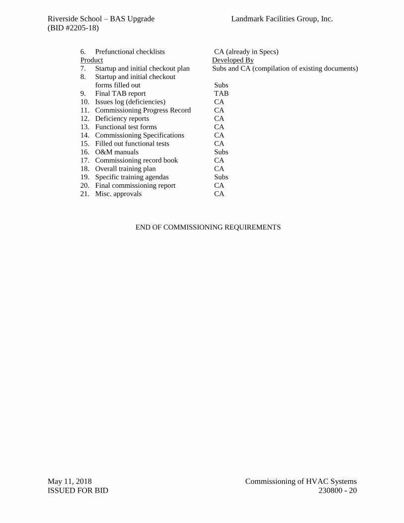
Riverside School – BAS Upgrade Landmark Facilities Group, Inc.
(BID #2205-18)
May 11, 2018 Commissioning of HVAC Systems
ISSUED FOR BID 230800 - 20
6. Prefunctional checklists CA (already in Specs)
Product Developed By
7. Startup and initial checkout plan Subs and CA (compilation of existing documents)
8. Startup and initial checkout
forms filled out Subs
9. Final TAB report TAB
10. Issues log (deficiencies) CA
11. Commissioning Progress Record CA
12. Deficiency reports CA
13. Functional test forms CA
14. Commissioning Specifications CA
15. Filled out functional tests CA
16. O&M manuals Subs
17. Commissioning record book CA
18. Overall training plan CA
19. Specific training agendas Subs
20. Final commissioning report CA
21. Misc. approvals CA
END OF COMMISSIONING REQUIREMENTS

Riverside School – BAS Upgrade Landmark Facilities Group, Inc.
(BID #2205-18)
May 11, 2018 230900 - 1
ISSUED FOR BID Instrumentation and Control for HVAC
SECTION 230900 – INSTRUMENTATION AND CONTROL FOR HVAC
1. GENERAL
1.1 Related Documents
A. All work of this Division shall be coordinated and provided by the Building Automation
System (BAS) Contractor.
B. The work of this Division shall be scheduled, coordinated, and interfaced with the associ-
ated work of other trades. Reference the Division 23 and 26 Sections for details.
C. The work of this Division shall be as required by the Specifications, Point Schedules and
Drawings.
D. If the BAS Contractor believes there are conflicts or missing information in the project
documents, the Contractor shall promptly request clarification and instruction from the
design team.
1.2 DEFINITIONS
A. Analog: A continuously variable system or value not having discrete levels. Typically
exists within a defined range of limiting values.
B. Binary: A two-state system where an “ON” condition is represented by one discrete sig-
nal level and an “OFF” condition is represented by a second discrete signal level.
C. Building Automation System (BAS): The total integrated system of fully operational and
functional elements, including equipment, software, programming, and associated materi-
als, to be provided by this Division BAS Contractor and to be interfaced to the associated
work of other related trades.
D. BAS Contractor: The Contractor to provide the work of this Division. This Contractor
shall be the primary manufacturer, installer, commissioner and ongoing service provider
for the BAS work.
E. Control Sequence: A BAS pre-programmed arrangement of software algorithms, logical
computation, target values and limits as required to attain the defined operational control
objectives.
F. Direct Digital Control: The digital algorithms and pre-defined arrangements included in
the BAS software to provide direct closed-loop control for the designated equipment and
controlled variables. Inclusive of Proportional, Derivative and Integral control algorithms
together with target values, limits, logical functions, arithmetic functions, constant values,
timing considerations and the like.
G. BAS Network: The total digital on-line real-time interconnected configuration of BAS
digital processing units, workstations, panels, sub-panels, controllers, devices and associ-
ated elements individually known as network nodes. May exist as one or more fully inter-
faced and integrated sub-networks, LAN, WAN or the like.
H. Node: A digitally programmable entity existing on the BAS network.
I. BAS Integration: The complete functional and operational interconnection and interfac-
ing of all BAS work elements and nodes in compliance with all applicable codes, stand-
ards and ordinances so as to provide a single coherent BAS as required by this Division.
J. Provide: The term “Provide” and its derivatives when used in this Division shall mean to
furnish, install in place, connect, calibrate, test, commission, warrant, document and sup-
ply the associated required services ready for operation.
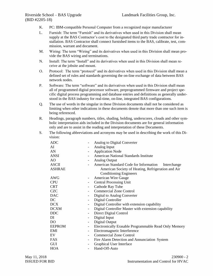
Riverside School – BAS Upgrade Landmark Facilities Group, Inc.
(BID #2205-18)
May 11, 2018 230900 - 2
ISSUED FOR BID Instrumentation and Control for HVAC
K. PC: IBM-compatible Personal Computer from a recognized major manufacturer
L. Furnish: The term “Furnish” and its derivatives when used in this Division shall mean
supply at the BAS Contractor’s cost to the designated third party trade contractor for in-
stallation. BAS Contractor shall connect furnished items to the BAS, calibrate, test, com-
mission, warrant and document.
M. Wiring: The term “Wiring” and its derivatives when used in this Division shall mean pro-
vide the BAS wiring and terminations.
N. Install: The term “Install” and its derivatives when used in this Division shall mean re-
ceive at the jobsite and mount.
O. Protocol: The term “protocol” and its derivatives when used in this Division shall mean a
defined set of rules and standards governing the on-line exchange of data between BAS
network nodes.
P. Software: The term “software” and its derivatives when used in this Division shall mean
all of programmed digital processor software, preprogrammed firmware and project spe-
cific digital process programming and database entries and definitions as generally under-
stood in the BAS industry for real-time, on-line, integrated BAS configurations.
Q. The use of words in the singular in these Division documents shall not be considered as
limiting when other indications in these documents denote that more than one such item is
being referenced.
R. Headings, paragraph numbers, titles, shading, bolding, underscores, clouds and other sym-
bolic interpretation aids included in the Division documents are for general information
only and are to assist in the reading and interpretation of these Documents.
S. The following abbreviations and acronyms may be used in describing the work of this Di-
vision:
ADC - Analog to Digital Converter
AI - Analog Input
AN - Application Node
ANSI - American National Standards Institute
AO - Analog Output
ASCII - American Standard Code for Information Interchange
ASHRAE American Society of Heating, Refrigeration and Air
Conditioning Engineers
AWG - American Wire Gauge
CPU - Central Processing Unit
CRT - Cathode Ray Tube
CZC - Commercial Zone Control
DAC - Digital to Analog Converter
DC - Digital Controller
DCX - Digital Controller with extension capability
DCXM - Digital Controller Master with extension capability
DDC - Direct Digital Control
DI - Digital Input
DO - Digital Output
EEPROM - Electronically Erasable Programmable Read Only Memory
EMI - Electromagnetic Interference
EV - Commercial Zone Control
FAS - Fire Alarm Detection and Annunciation System
GUI - Graphical User Interface
HOA - Hand-Off-Auto
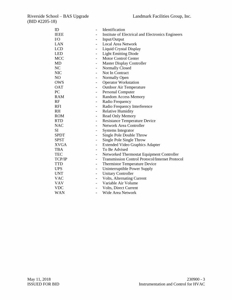
Riverside School – BAS Upgrade Landmark Facilities Group, Inc.
(BID #2205-18)
May 11, 2018 230900 - 3
ISSUED FOR BID Instrumentation and Control for HVAC
ID - Identification
IEEE - Institute of Electrical and Electronics Engineers
I/O - Input/Output
LAN - Local Area Network
LCD - Liquid Crystal Display
LED - Light Emitting Diode
MCC - Motor Control Center
MD - Master Display Controller
NC - Normally Closed
NIC - Not In Contract
NO - Normally Open
OWS - Operator Workstation
OAT - Outdoor Air Temperature
PC - Personal Computer
RAM - Random Access Memory
RF - Radio Frequency
RFI - Radio Frequency Interference
RH - Relative Humidity
ROM - Read Only Memory
RTD - Resistance Temperature Device
NAC - Network Area Controller
SI - Systems Integrator
SPDT - Single Pole Double Throw
SPST - Single Pole Single Throw
XVGA - Extended Video Graphics Adapter
TBA - To Be Advised
TEC - Networked Thermostat Equipment Controller
TCP/IP - Transmission Control Protocol/Internet Protocol
TTD - Thermistor Temperature Device
UPS - Uninterruptible Power Supply
UNT - Unitary Controller
VAC - Volts, Alternating Current
VAV - Variable Air Volume
VDC - Volts, Direct Current
WAN - Wide Area Network
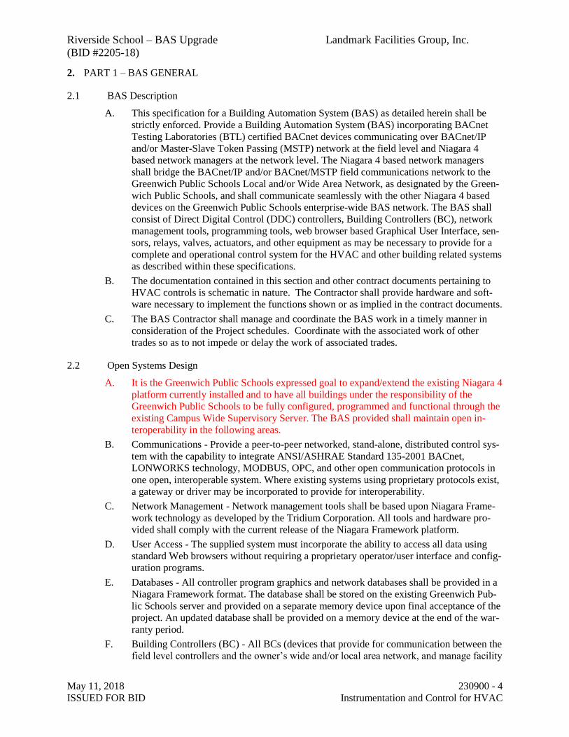
Riverside School – BAS Upgrade Landmark Facilities Group, Inc.
(BID #2205-18)
May 11, 2018 230900 - 4
ISSUED FOR BID Instrumentation and Control for HVAC
2. PART 1 – BAS GENERAL
2.1 BAS Description
A. This specification for a Building Automation System (BAS) as detailed herein shall be
strictly enforced. Provide a Building Automation System (BAS) incorporating BACnet
Testing Laboratories (BTL) certified BACnet devices communicating over BACnet/IP
and/or Master-Slave Token Passing (MSTP) network at the field level and Niagara 4
based network managers at the network level. The Niagara 4 based network managers
shall bridge the BACnet/IP and/or BACnet/MSTP field communications network to the
Greenwich Public Schools Local and/or Wide Area Network, as designated by the Green-
wich Public Schools, and shall communicate seamlessly with the other Niagara 4 based
devices on the Greenwich Public Schools enterprise-wide BAS network. The BAS shall
consist of Direct Digital Control (DDC) controllers, Building Controllers (BC), network
management tools, programming tools, web browser based Graphical User Interface, sen-
sors, relays, valves, actuators, and other equipment as may be necessary to provide for a
complete and operational control system for the HVAC and other building related systems
as described within these specifications.
B. The documentation contained in this section and other contract documents pertaining to
HVAC controls is schematic in nature. The Contractor shall provide hardware and soft-
ware necessary to implement the functions shown or as implied in the contract documents.
C. The BAS Contractor shall manage and coordinate the BAS work in a timely manner in
consideration of the Project schedules. Coordinate with the associated work of other
trades so as to not impede or delay the work of associated trades.
2.2 Open Systems Design
A. It is the Greenwich Public Schools expressed goal to expand/extend the existing Niagara 4
platform currently installed and to have all buildings under the responsibility of the
Greenwich Public Schools to be fully configured, programmed and functional through the
existing Campus Wide Supervisory Server. The BAS provided shall maintain open in-
teroperability in the following areas.
B. Communications - Provide a peer-to-peer networked, stand-alone, distributed control sys-
tem with the capability to integrate ANSI/ASHRAE Standard 135-2001 BACnet,
LONWORKS technology, MODBUS, OPC, and other open communication protocols in
one open, interoperable system. Where existing systems using proprietary protocols exist,
a gateway or driver may be incorporated to provide for interoperability.
C. Network Management - Network management tools shall be based upon Niagara Frame-
work technology as developed by the Tridium Corporation. All tools and hardware pro-
vided shall comply with the current release of the Niagara Framework platform.
D. User Access - The supplied system must incorporate the ability to access all data using
standard Web browsers without requiring a proprietary operator/user interface and config-
uration programs.
E. Databases - All controller program graphics and network databases shall be provided in a
Niagara Framework format. The database shall be stored on the existing Greenwich Pub-
lic Schools server and provided on a separate memory device upon final acceptance of the
project. An updated database shall be provided on a memory device at the end of the war-
ranty period.
F. Building Controllers (BC) - All BCs (devices that provide for communication between the
field level controllers and the owner’s wide and/or local area network, and manage facility

Riverside School – BAS Upgrade Landmark Facilities Group, Inc.
(BID #2205-18)
May 11, 2018 230900 - 5
ISSUED FOR BID Instrumentation and Control for HVAC
global functions such as alarms, trends, schedules and normalization of data) shall con-
form to the current release of the Niagara Framework.
G. All Niagara 4 Network Manager controllers (BC) shall be integrated into the existing
Greenwich Public Schools Campus Wide Supervisory Server. All local control program-
ming shall reside on the network managers to maintain standalone control and all system
wide programming and all graphical images shall be hosted and served by the supervisory
server. The Greenwich Public Schools will supply all required static IP addresses as nec-
essary to accommodate multiple BC’s per building.
H. Direct Digital Controllers (DDC) - All DDC devices for HVAC system control, with the
exception of DDC devices furnished as part of any OEM control packages, shall be certi-
fied to the current BTL standards appropriate to their application provided an appropriate
BTL Certification standard exist. All points within a controller including hard I/O and
software based points shall be available for viewing, management, and manipulation
through the Niagara Framework tools.
I. Software Tools - All software tools needed for full functional use, including programming
of BCs and DDC, network management and expansion, and graphical user interface de-
velopment, of the BAS described within these specifications, shall be provided to the
Greenwich Public Schools or their designated agent. Any licensing required by the manu-
facturer now and into the future, including changes to the licensee of the software tools
and the addition of hardware corresponding to the licenses, to allow for a complete and
operational system for both normal day to day operation and servicing shall be provided.
Any change to the designated license holders shall be made by the manufacturer, upon
written request by the owner or his agent. Any license changes shall be identified within
the BAS submittals.
J. Programming Tools - Provide freely available Niagara 4 Wizards to facilitate the pro-
gramming and configuration of all of the DDC devices that are provided for the HVAC
system control. Wizards shall be provided free of charge and be compatible with the cur-
rent published versions of the network management tool that is provided as part of this
project. The Wizard software shall be available for public access from the manufacturer’s
web site. These Wizard programming tools shall be compatible with at least 3 other
brands of the Niagara Framework network management tools. The SI shall demonstrate as
part of their prequalification how they intend to comply with these requirements.
K. Software License Agreement - The Owner shall sign a copy of the manufacturer's stand-
ard software and firmware licensing agreement as a condition of this contract. Such li-
cense shall grant use of all programs and application software to Owner as defined by the
manufacturer's license agreement, but shall protect manufacturer's rights as it relates to
disclosure of trade secrets contained within said software. The Owner shall be the named
license holder of all software associated with any and all incremental work on the project.
In addition, the Owner shall receive ownership of all job specific configuration documen-
tation, data files, and application-level software developed for the project. This shall in-
clude all custom, job specific software code, databases and documentation for all configu-
ration and programming that is generated for a given project and/or configured for use
with the BC and any related LAN / WAN / Intranet and Internet connected routers and
devices. Any and all required IDs and passwords for access to any component or software
program shall be provided to the owner.
L. The System Integrator shall provide as part of the submittals a copy of the Niagara Com-
patibility Statement (NiCS) verifying that all aspect of the Niagara Framework as pro-
vided maintains an Open System Design.
Riverside School – BAS Upgrade Landmark Facilities Group, Inc.
(BID #2205-18)
May 11, 2018 230900 - 6
ISSUED FOR BID Instrumentation and Control for HVAC
2.3 Quality Assurance
A. The HVAC control system shall be furnished, engineered, and installed by a licensed
Controls Contractor or System Integrator (SI). All work provided under this section shall
be provided by direct employees of the SI or under the direct supervision of the SI person-
nel.
B. System Integrator Qualifications
1. The SI must be regularly engaged in the service and installation of LONWORKS,
BACnet, and Niagara based systems as specified herein, The SI shall have a mini-
mum of 5 years of experience in the sales, installation, engineering, programming
servicing and commissioning of the Niagara platform and the field controllers as
proposed.
2. The system integrator must be an authorized factory direct representative in good
standing of the manufacturer of the proposed hardware and software components.
Provide a letter dated within the last 6 months, from the manufacture certifying
that the System Integrator is an authorized factory direct representative.
3. . The SI shall have an office within 75 miles of the Building site that is staffed with
a minimum of five (5) technicians who have successfully completed the factory
authorized training of the proposed manufactures hardware and software compo-
nents and have successfully completed a Niagara4 certification course. SI must
provide proof of required training. The SI capabilities shall include engineering
and design of control systems, programming, electrical installation of control sys-
tems, troubling shooting and service.
4. The SI shall submit a list of no less than three (3) similar projects, which have
similar Building Automation Systems as specified herein installed by the SI.
These projects must be on-line and functional such that the Owner /User’s repre-
sentative can observe the system in full operation.
C. Hardware and Software Component Manufacturer Qualifications
1. The manufacturer of the hardware and software components must be primarily
engaged in the manufacture of both BACnet-IP and BACnet MSTP based systems
as specified herein, and must have been so for a minimum of five (5) years. The
manufacturer shall demonstrate that they are the manufacturer of all DDC devices
and Niagara 4 products provided.
2. The manufacturer of the hardware and software components as well as its subsidi-
aries must be a member in good standing of the BACnet International, and the
BACnet Manufacturers Association.
3. The manufacturer of the hardware and software components shall have a technical
support group accessible via a toll free number that is staffed with qualified per-
sonnel, capable of providing instruction and technical support service for net-
worked control systems.
2.4 Submittals
A. Submit six (6) complete sets of documentation in the following phased delivery schedule:
1. Valve and damper schedules.
2. Equipment data cut sheets.
3. System schematics, including:
a. Sequence of operations.
Riverside School – BAS Upgrade Landmark Facilities Group, Inc.
(BID #2205-18)
May 11, 2018 230900 - 7
ISSUED FOR BID Instrumentation and Control for HVAC
b. Point names.
c. Point addresses.
d. Point to point wiring.
e. Interface wiring diagrams.
f. Panel layouts.
g. System riser diagrams.
4. Visio or AutoCAD compatible as-built drawings.
B. Upon project completion, submit operation and maintenance manuals, consisting of the
following:
1. Index sheet, listing contents in alphabetical order.
2. Manufacturer's equipment parts list of all functional components of the system,
disk of system schematics, including wiring diagrams.
3. Description of sequence of operations.
4. As-Built interconnection wiring diagrams.
5. User’s documentation containing product, system architectural and programming
information.
6. Trunk cable schematic showing remote electronic panel locations, and all trunk
data.
7. List of connected data points, including panels to which they are connected and
input device (ionization detector, sensors, etc.).
8. Copy of the warranty.
9. Recommended spare parts list.
2.5 Training
A. Instruct the operators how to accomplish control of the system. Include basic trouble-
shooting and override of equipment and controls in the event of system failure.
B. Training Allowance: Provide not less than 32 hours formal training to the Owner’s desig-
nated operations personnel.
C. Trainers - Persons conducting the training shall hold a Niagara 4 certification, be knowl-
edgeable in the workings of the system, and shall be regularly engaged in training exer-
cises, so as to provide effective training.
D. Training Classes - Prior to conducting training, prepare and submit for approval the pro-
posed training literature and topics. Submit this information at least two weeks prior to the
first class.
E. Training - Manufacturer provided training on the use and operation of all products pro-
vided within these specifications shall be available for purchase and attendance by the
Owner or his designated agent. Such training shall be of the same curriculum as the train-
ing courses provided by the manufacturer to the System Integrator. A manufacturer ad-
vanced certified instructor shall give all training classes. A list of training courses and the
associated cost shall be provided as part of the BAS submittals.
2.6 Warranty
A. The HVAC Control System shall be free from defects in workmanship and material under
normal use and service. If within twelve (12) months from the date of substantial comple-
tion, or the owner receives beneficial use of the system, the installed equipment is found

Riverside School – BAS Upgrade Landmark Facilities Group, Inc.
(BID #2205-18)
May 11, 2018 230900 - 8
ISSUED FOR BID Instrumentation and Control for HVAC
to be defective in operation, workmanship or materials, the building systems contractor
shall replace, repair or adjust the defect at no cost. Service shall be provided within the
next business day upon notice from Owner’s designated representative.
B. The warranty shall extend to material that is supplied and installed by the Contractor. Ma-
terial supplied but not installed by the Contractor shall be covered per the above to the ex-
tent of the product only. Installation labor shall be the responsibility of the trade contrac-
tor performing the installation.
C. All corrective software modifications made during warranty service periods shall be up-
dated on all user documentation and on user and manufacturer archived software disks.
2.7 Ownership of Proprietary Material
A. Project-specific software and documentation shall become Owner's property. This in-
cludes, but is not limited to:
1. Graphics.
2. Record drawings.
3. Database.
4. Application programming code.
5. Documentation.
6. Provide to the owner the highest level administrative password for the system.
This password is not used by the owner during the warranty period to prevent
possible voiding of warranty and negative impact on system operation.
3. PART 2 – PRODUCTS
3.1 Acceptable Manufacturers
A. Acceptable manufacturers of the hardware and software components as specified herein
are as follows:
1. Distech Controls – EC-Net Niagara 4
2. Johnson Controls – Facility Explorer Niagara 4
3. Vykon – Niagara 4
4. Siemens TNM-8000 Niagara 4
B. Inclusion on this list does not guarantee acceptance of products or installation. Control
systems shall comply with the terms of this specification.
C. Owner shall reserve the right to reject, at their option, any and all bids that do not meet the
specified requirements stated.
D. Controls shall be microprocessor based Interoperable Niagara 4 Controllers in accordance
with the JSR-60 Baja Specification.
1. The Contractor shall use only controller software, custom application program-
ming language, and controllers from the corresponding manufacturer and product
line. All field level controllers must be fully configurable through the Niagara 4
automation level controller and the existing Niagara 4 Supervisory server located
at the Greenwich High School. No additional tools, software or links to other
servers/computers/systems shall be installed on this server.
2. Other products specified herein (such as sensors, valves, dampers, and actuators)
need not be manufactured by the above manufacturers.
Riverside School – BAS Upgrade Landmark Facilities Group, Inc.
(BID #2205-18)
May 11, 2018 230900 - 9
ISSUED FOR BID Instrumentation and Control for HVAC
3.2 Networks
A. All Niagara 4 based network managers supplied under this section shall bridge the Lon-
works, BACnet or Modbus field bus to the owner’s Local Area Network (LAN) and/or
Wide Area Network (WAN) as designated by the owner. The network managers shall
communicate at no less than 100 Megabits/sec over the Ethernet network and shall sup-
port BACnet over IP, Java, XML, HTTP, Fox and SOAP for maximum flexibility as it
relates to the integration of building data with enterprise information systems. The system
shall provide support for multiple network managers, Building Controllers (BC), user
workstations and, if specified, a local server. The WAN and/or LAN will be provided by
others. The SI shall coordinate with the General Contractor for the access to the WAN
and/or LAN.
B. Network minimum physical and media access requirements:
1. Ethernet; IEEE standard 802.3.
2. Cable; 100 Base-T, UTP-8 wire, category 5 Minimum throughput; 100 Mbps.
C. Network Access - Remote Access - For Local Area Network installations; provide access
to the WAN and/or LAN from a remote location, via the Internet. The Owner shall pro-
vide a connection to the Internet to enable access via high-speed cable modem, asynchro-
nous digital subscriber line (ADSL) modem, ISDN line, T1 Line or via the customer’s In-
tranet to a corporate server providing access to an Internet Service Provider (ISP). The
Owner agrees to pay monthly access charges for connection and ISP.
3.3 Field Level Controllers
A. The communication network between the field level controllers shall be BACnet/IP or
BACnet MSTP. All wiring shall be provided in accordance with the standards for the ap-
propriate protocol. The number of devices on any one network shall not exceed 90% of
capacity.
3.4 Network Management Devices
A. Supervisory Server Hardware Requirements
1. Provide a Server Quality PC with Intel Core i5 Quad core 3.4 GHz processor with 16
GB RAM and a 1TB SATA hard drive with 6 GB/s transfer rate. It shall include a
minimum of 4-USB ports, HDMI, DVI-D video interfaces, 1GB Network Interface
Card. A minimum 21”Widescreen, LED color monitor with a minimum 60 Hz re-
fresh rate shall also be included with keyboard, mouse and all peripherals needed for
a complete operating computer.
2. The operating system shall be Windows 10 Pro 64-bit with the most recent service
packs and system updates.
3. Alternatively BMS Contractor should coordinate with the owner for a Virtual server
partitioned from their existing town server platform for use of the BMS system. This
contractor shall purchase, install and license to the owner a Niagara4 Supervisory
Software and use the server to integrate these projects into one common platform.
Contractor shall also purchase a three (3) year (SMA) Service Maintenance Agree-
ment and keep this server up to date during the warranty period.
B. These various devices will service multiple functions on the network depending on net-
work design, communication medium and needed task. These functions can include: man-
agement of traffic on the network, reconfiguring and strengthening of signals, the conver-

Riverside School – BAS Upgrade Landmark Facilities Group, Inc.
(BID #2205-18)
May 11, 2018 230900 - 10
ISSUED FOR BID Instrumentation and Control for HVAC
sion of protocols, normalizing of data, global management of alarms, trends and sched-
ules, control logic, protocol conversion and web page hosting for use as a Graphical User
Interface.
C. Building Controller (BC) – This Niagara Framework based device shall provide the inter-
face between the LAN or WAN and the field control devices, and provide global supervi-
sory control functions over the control devices connected to the BC.
1. BC shall be provided with the following features:
a. Web page hosting
b. Network management tools resident within the BC.
c. Appropriate hardware and driver(s) associated with the protocol it manages.
d. Software Maintenance Agreement appropriate for the Core Device Software
purchased with a minimum term not to expire before the warranty period
ends.
2. Provide multiple Building Controllers as necessary. In order to maintain peak per-
formance of the network, limit the maximum consumed resources to 70 percent as
indicated by the resource meter resident in the network management tools.
3. Provide for the creation of a minimum of eight alarm classes for the purpose of
routing types and or classes of alarms. Alarms shall consist of all alarm outputs
for major or critical equipment as coordinated with the owner.
4. Alarms shall be annunciated in any of the following manners as defined by the
user:
a. Screen message text
b. Graphic with flashing alarm object(s)
c. Email of the complete alarm message to multiple recipients.
d. Pagers via paging services that initiate a page on receipt of email message
e. Printed message, routed directly to a dedicated alarm printer
D. LON to LON and BACnet Routers and Repeaters – A router or repeater may be used on a
LON segment between controllers and a BC as a means to manage traffic and reconfigure
and strengthen a transmission signal. Routers shall be fully programmable and permit a
systems integrator to define message traffic, destination, and other network management
functions utilizing LONWORKS. A repeater or signal booster may only be used to in-
crease this signal strength of the communications. Under no circumstances may it be used
in the place of a router.
E. Existing Niagara 4 Supervisory Server – The entire building management system shall be
integrated into the existing Niagara 4 campus-wide supervisor located at Greenwich High
School. All programming and configuration on the existing Niagara 4 Web Supervisor
must be performed by Connecticut Temperature Controls as this company is responsible
for this software’s proper function and energy performance under current projects with
Greenwich Public Schools. Connecticut Temperature Controls must perform all work in-
tegrating this project into this software and server. This Contractor shall include all costs
associated with the server integration and programming. Contractor shall contact CTC
Sales Department at (800) 890-2022.
3.5 Building Automation System Controllers
A. All controllers shall be designed for easy installation and servicing including removable
enclosures, removable terminals, and factory applied labels for all I/O. All internal points
within the Programmable Controllers shall be fully supported by the Graphical User Inter-
face (GUI), allowing the user to easily modify them and monitor them. All of the internal
Riverside School – BAS Upgrade Landmark Facilities Group, Inc.
(BID #2205-18)
May 11, 2018 230900 - 11
ISSUED FOR BID Instrumentation and Control for HVAC
programming points (e.g. variables, constants, PID’s, timers, inputs and outputs) shall be
exposed to the network on dedicated network variable outputs. All controllers programs
and schedules shall contain non-volatile flash memory. Upon a loss of power all control-
lers shall perform a self- restart.
B. Programmable Controllers (PC) – a controller designed for more complex sequences of
operations such as built up AHU, central plant operations, electrical monitoring, and con-
trol and management for chillers, boilers and generators. The PCs are to allow for the
flexibility of custom control programming to meet the needed sequences of operation.
C. Provide software selectable universal inputs. Analog inputs shall have the following mini-
mum level of performance: 16 bit A to D resolution for all terminal box applications, 12
bit A to D resolution for all other configurable applications, manages thermistors with an
accuracy of: +/-0.5oC; +/-0.9oF, and a Potentiometer. For VAV Applications provide a
differential pressure input sensor built in to the controller with a 16 bit A to D resolution
and an adjustable range of 0” to 1” H20 (0-248.8 Pa) static pressure with a minimum ac-
curacy of ±3%. Minimum response time shall be 0.5 seconds from input to output time.
D. Analog outputs shall have the following minimum level of performance: Tri-mode Volt-
age of 0-10 VDC (linear), digital 0-12 VDC (off/on) or PWM. All analog outputs shall be
equipped with an auto-reset fuse. Output Resolution shall be a minimum 8 bits digital /
analog converter. Digital outputs shall be provided with a minimum of a triac output rated
at 24VAC and 1 amp. All analog outputs shall be fuse protected.
E. Programmable Controller Features
1. Provide an onboard network communication jack
2. The PC shall be provided with a diagnostic indicator lights for power and network
communication of transmit and receive along with a light indication position for
each output
3. Full-Color Backlit-Display Operator Interface – For all controllers applied to an
AHU, Chiller, Pumps Cooling Tower or Boiler Plant, provide a controller with a
fully integrated display interface for manual override and adjustment of all Ana-
log and Digital outputs. The display operator interface shall be an integral part of
the controller. Display interface external from the controller shall not be accepted.
a. Full-color backlit display and a jog dial for turn and select navigation to access a
wide range of internal controller functions:
i. View and override values. The status is color coded to show if the value
is overridden.
ii. Visually tune PID loops with system response graphing.
iii. View active alarm list including details and acknowledge alarms.
iv. View and modify schedules and calendars through a graphic interface.
Also create or delete schedule events, special events, and calendar en-
tries.
v. Create a list of favorites to provide quick access to commonly-used
values.
vi. Multi-User access management.
4. Enclosures – Provide for an enclosure with a separate back plate with terminals
such that the electronic portion of the controller can be easily removed for ease of
installation and servicing.
F. Configurable Controllers (CC) - A controller designed through its I/O configuration and
configurable control logic to be used for a specific type mechanical equipment.

Riverside School – BAS Upgrade Landmark Facilities Group, Inc.
(BID #2205-18)
May 11, 2018 230900 - 12
ISSUED FOR BID Instrumentation and Control for HVAC
1. Provide software selectable universal inputs. Analog inputs shall have the follow-
ing minimum level of performance: 16 bit A to D resolution for all terminal box
applications, 12 bit A to D resolution for all other configurable applications, man-
age thermistors with an accuracy of: +/- 0.5oC; +/- 0.9oF, and a Potentiometer
2. Output – Analog outputs shall have the following minimum level of perfor-
mance: Tri-mode Voltage of 0-10 VDC (linear), digital 0-12 VDC (off/on) or
PWM. All analog outputs shall be equipped with an auto reset fuse. Output Reso-
lution shall be a minimum 8 bits digital / analog converter. Digital outputs shall
be provided with a minimum of a triac output rated at 24VAC and 1 amp. All an-
alog outputs shall be fuse protected
3. Configurable Controller Features:
4. The CC (except for the VAV controller) shall be provided with an optimum start
program internal to its control logic. The optimum start shall be activated by an
event signal from its associated scheduler on the network.
5. The CC shall allow the use of its spare I/O as dumb I/O to be shared over the net-
work to other controllers such as PC or the Building Controller (BC), where a se-
quence of operation can be applied to the I/O. Such applications shall include but
not be limited to exhaust fan control, heaters, light control, etc.
6. Enclosures – Provide for all CC (except for the VAV), an enclosure with a sepa-
rate back plate with terminals such that the electronic portion of the controller can
be easily removed for ease of installation and servicing.
7. VAV Specific functions. In addition to the features for the CC, VAV controller
shall provide the following functions:
8. The CC VAV shall be a single integrated package consisting of a microprocessor,
power supply, damper actuator, differential pressure transducer, field termina-
tions, and application software. All input/output signals shall be directly hard-
wired to the CC VAV controller. The internal actuator shall employ a manual
override that allows for powered or non-powered adjustment of the damper posi-
tion. In all cases, the controller shall automatically resume proper operation fol-
lowing the return of power to, or control by the CC VAV. Programming, config-
uring and/or troubleshooting of input/output signals shall be easily executed
through the CC VAV sensor at the wall sensor location through the requisite LON
connection.
9. The CC VAV control algorithms shall be designed to limit the frequency of
damper repositioning, to extend the life of the components. The CC VAV shall
provide an internal differential pressure transducer. Flows through transducers
requiring filter maintenance are not acceptable. The CC VAV shall provide zone
control accuracy equal to or better than +/- 1 degree Fahrenheit. With the submit-
tal package, supplier/provider shall provide performance data that verifies control
accuracy of the CC VAV.
10. Accept platinum 1K ohm and/or thermistor 10K ohms type II sensors
11. Configuration of all I/O points shall be accomplished without physical hardware
jumpers, switches or settings.
12. The built in actuator shall be a brushless constant speed actuator with direct feed-
back of the actuator position.
4. PART 4 – BAS SOFTWARE TOOLS
Riverside School – BAS Upgrade Landmark Facilities Group, Inc.
(BID #2205-18)
May 11, 2018 230900 - 13
ISSUED FOR BID Instrumentation and Control for HVAC
4.1 Requirements
A. Provide three (3) copies of all tools necessary for the development, maintenance, expan-
sion and use of the BAS described within these specifications. All software tools shall be
a part of the Niagara Framework tools or be provided as Wizards that operates within the
Niagara Framework environment. For the purpose of this specification software tools
shall be divided into the following categories and meet these specified requirements.
B. Controller Programming Software
1. Provide Wizards or objects that facilitate the programming and configuration of
the Configurable Controllers (CC), Programmable Controller (PC) sequence of
operation through menu driven wizard. The programming tools shall perform the
following functions:
a. PC programming shall be accomplished by graphical programming language
(GPL) where objects are used to define different portions of the control se-
quence. All control sequences programmed into the PC shall be stored in
non-volatile memory. All code must be exportable to a library for future use.
b. Provide for the programming of the required sequence of operation through
an intuitive configuration menu driven selection process. The configuration
tools menu shall define items such as I/O configurations, set point, delays,
PID loops, optimum start stops, and network variables settings. The configu-
ration tool must indicate the device status and allows system override.
Graphical programming language as described for the PC is acceptable.
C. The Graphical User Interface (GUI) shall employ browser-like functionality for ease of
navigation. It shall include a tree view for quick viewing of, and access to, the hierar-
chical structure of the database. In addition, menu-pull downs, and toolbars shall employ
buttons, commands and navigation to permit the operator to perform tasks with a mini-
mum knowledge of the HVAC control system and basic computing skills. These shall
include, but are not limited to, forward/backward buttons, home button, and a context sen-
sitive locator line (similar to a URL line), that displays the location and the selected object
identification.
1. Provide a visual graphical representation of each piece of mechanical equipment
and/or mechanical system that duplicates the represented system, where applica-
ble. Graphics shall include at a minimum the value of each input, each output,
each setpoint, and alarms. The graphic shall provide for the ability to command
each point, including both timed and permanent overrides. In addition, provide for
all information represented in the graphics in an associated graphical table with
links to the equipment graphics and command able points. All graphics shall com-
ply with the latest industries standards and practices. Sample graphics shall be
provided as part of the submittals for approval by owner.
2. The GUI, shall at a minimum, support the following graphical features and func-
tions:
a. Graphic screens shall be developed using any drawing package capable of
generating or assembling objects from a GIF, or JPG file format. Use of pro-
prietary graphic file formats shall not be acceptable. In addition to, or in lieu
of a graphic background, the GUI shall support the use of scanned pictures.
b. Graphic screens shall have the capability to contain objects for text, real-
time values, animation, color spectrum objects, logs, graphs, HTML or XML
document links, schedule objects, hyperlinks to other URL’s, and links to
other graphic screens.
Riverside School – BAS Upgrade Landmark Facilities Group, Inc.
(BID #2205-18)
May 11, 2018 230900 - 14
ISSUED FOR BID Instrumentation and Control for HVAC
c. Modifying common application objects, such as schedules, calendars, and
set points shall be accomplished in a graphical manner.
d. Schedule times will be adjusted using a graphical slider, without requiring
any keyboard entry from the operator.
e. Holidays shall be set by using a graphical calendar, without requiring any
keyboard entry from the operator.
f. Commands to start and stop binary objects shall be done by right-clicking
the selected object and selecting the appropriate command from the pop-up
menu. No entry of text shall be required.
g. Adjustments to analog objects, such as set points, shall be done by right-
clicking the selected object and using a graphical slider to adjust the value.
No entry of text shall be required.
3. System Configuration. At a minimum, the GUI shall permit the operator to per-
form the following tasks, with proper password access:
a. . Create, delete or modify control strategies.
b. Add/delete objects to the system.
c. Tune control loops through the adjustment of control loop parameters.
d. Enable or disable control strategies.
e. Generate hard copy records or control strategies on a printer.
f. Select points to be alarm-able and define the alarm state.
g. Select points to be trended over a period of time and initiate the recording of
values automatically.
D. Provide a context sensitive, on-line help system to assist the operator in operation and ed-
iting of the system. On-line help shall be available for all applications and shall provide
the relevant data for that particular screen. Additional help information shall be available
through the use of hypertext. All system documentation and help files shall be in HTML
format.
E. Each operator shall be required to log on to that system with a user name and password in
order to view, edit, add, or delete data. System security shall be selectable for each opera-
tor. The system administrator shall have the ability to set passwords and security levels for
all other operators. Each operator password shall be able to restrict the operators’ access
for viewing and/or changing each system application, full screen editor, and object. Each
operator shall automatically be logged off of the system if no keyboard or mouse activity
is detected. This auto log-off time shall be set per operator password. All system security
data shall be stored in an encrypted format.
F. The system shall automatically monitor the operation of all workstations, printers, mo-
dems, network connections, building management panels, and controllers. The failure of
any device shall be annunciated to the operator.
G. Web Browser Clients shall have user access to all system data either locally over a secure
Intranet within the building or by remote access by a standard Web Browser over the In-
ternet.
5. PART 5 – USER INTERFACES
A. Web Browser Clients – shall be capable of total integration with the existing facility infra-
structure systems with user access to all system data either locally over a secure Intranet
within the building or by remote access by a standard Web Browser over the Internet.
Systems requiring additional software (to enable a standard Web browser) to be resident
on a client machine, or manufacture-specific browsers shall not be acceptable.
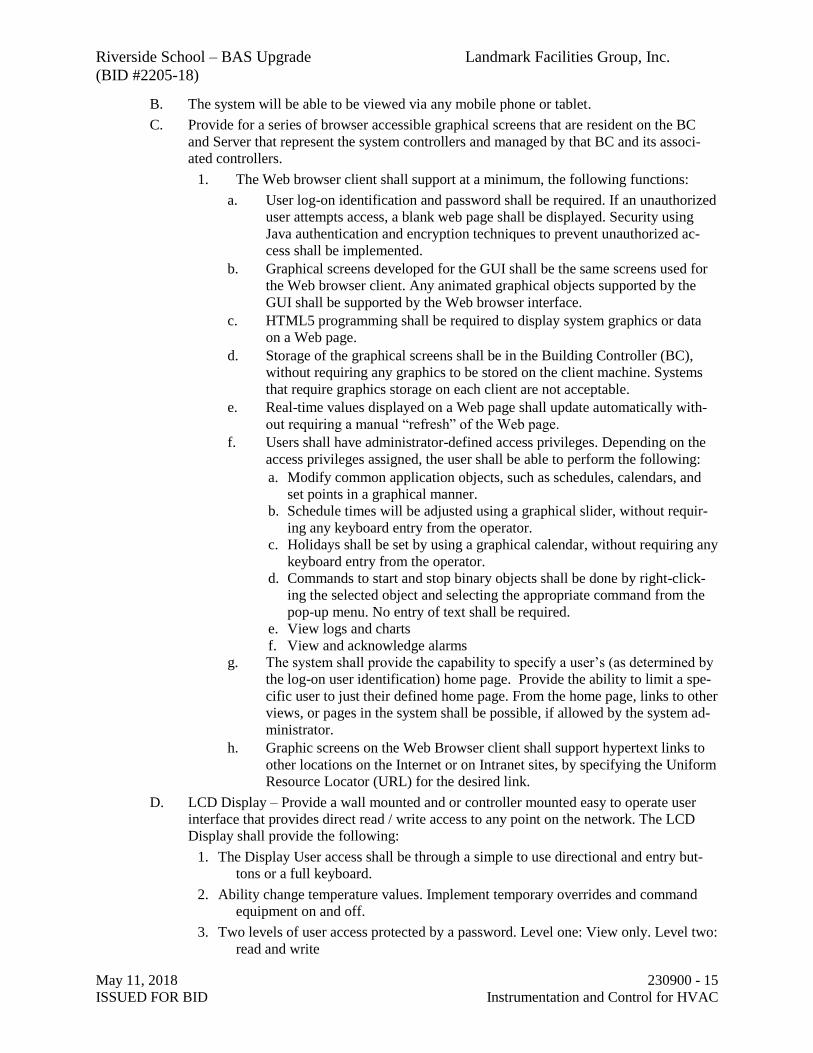
Riverside School – BAS Upgrade Landmark Facilities Group, Inc.
(BID #2205-18)
May 11, 2018 230900 - 15
ISSUED FOR BID Instrumentation and Control for HVAC
B. The system will be able to be viewed via any mobile phone or tablet.
C. Provide for a series of browser accessible graphical screens that are resident on the BC
and Server that represent the system controllers and managed by that BC and its associ-
ated controllers.
1. The Web browser client shall support at a minimum, the following functions:
a. User log-on identification and password shall be required. If an unauthorized
user attempts access, a blank web page shall be displayed. Security using
Java authentication and encryption techniques to prevent unauthorized ac-
cess shall be implemented.
b. Graphical screens developed for the GUI shall be the same screens used for
the Web browser client. Any animated graphical objects supported by the
GUI shall be supported by the Web browser interface.
c. HTML5 programming shall be required to display system graphics or data
on a Web page.
d. Storage of the graphical screens shall be in the Building Controller (BC),
without requiring any graphics to be stored on the client machine. Systems
that require graphics storage on each client are not acceptable.
e. Real-time values displayed on a Web page shall update automatically with-
out requiring a manual “refresh” of the Web page.
f. Users shall have administrator-defined access privileges. Depending on the
access privileges assigned, the user shall be able to perform the following:
a. Modify common application objects, such as schedules, calendars, and
set points in a graphical manner.
b. Schedule times will be adjusted using a graphical slider, without requir-
ing any keyboard entry from the operator.
c. Holidays shall be set by using a graphical calendar, without requiring any
keyboard entry from the operator.
d. Commands to start and stop binary objects shall be done by right-click-
ing the selected object and selecting the appropriate command from the
pop-up menu. No entry of text shall be required.
e. View logs and charts
f. View and acknowledge alarms
g. The system shall provide the capability to specify a user’s (as determined by
the log-on user identification) home page. Provide the ability to limit a spe-
cific user to just their defined home page. From the home page, links to other
views, or pages in the system shall be possible, if allowed by the system ad-
ministrator.
h. Graphic screens on the Web Browser client shall support hypertext links to
other locations on the Internet or on Intranet sites, by specifying the Uniform
Resource Locator (URL) for the desired link.
D. LCD Display – Provide a wall mounted and or controller mounted easy to operate user
interface that provides direct read / write access to any point on the network. The LCD
Display shall provide the following:
1. The Display User access shall be through a simple to use directional and entry but-
tons or a full keyboard.
2. Ability change temperature values. Implement temporary overrides and command
equipment on and off.
3. Two levels of user access protected by a password. Level one: View only. Level two:
read and write

Riverside School – BAS Upgrade Landmark Facilities Group, Inc.
(BID #2205-18)
May 11, 2018 230900 - 16
ISSUED FOR BID Instrumentation and Control for HVAC
E. LCD Sensor - Where required provide for a LCD based sensor to connect to the VAV
and or FCU that operates as a user interface for temperature adjustment, override and dis-
play of values along with the ability to perform Air Balance task (for VAV) and initial
program set up.
F. Reports and Summaries
1. Reports and Summaries shall be generated and directed to the user interface dis-
plays, with subsequent assignment to printers, or disk. As a minimum, the system
shall provide the following reports:
All points in the BAS
All points in each BAS application
All points in a specific controller
All points in a user-defined group of points
All points currently in alarm
All BAS schedules
All user defined and adjustable variables, schedules, interlocks and the like.
Reports shall be exportable to .pdf, .txt, or .csv formats.
The system shall allow for the creation of custom reports and queries.
G. Schedules
1. A graphical display for time-of-day scheduling and override scheduling of building
operations shall be provided. At a minimum, the following functions shall be pro-
vided:
Regular schedules
Repeating schedules
Exception Schedules
2. Weekly schedules shall be provided for each group of equipment with a specific time
use schedule.
3. It shall be possible to define one or more exception schedules for each schedule in-
cluding references to calendars
4. Monthly calendars shall be provided that allow for simplified scheduling of holidays
and special days. Holidays and special days shall be user-selected with the pointing
device or keyboard.
H. Password
1. Multiple-level password access protection shall be provided to allow the user/manager
to user interface control, display, and data manipulation capabilities deemed appropri-
ate for each user, based on an assigned password.
2. Each user shall have the following: a user name, a password, and access levels.
3. The system shall provide the capability to require a password of minimum length and
require a combination of characters and numerical or special characters.
4. When entering or editing passwords, the system shall not echo the actual characters
for display on the monitor.
5. The system shall provide unlimited flexibility with access rights. A minimum of four
levels of access shall be provided along with the ability to customize the system to
provide additional levels.
6. A minimum of 100 unique passwords shall be supported.
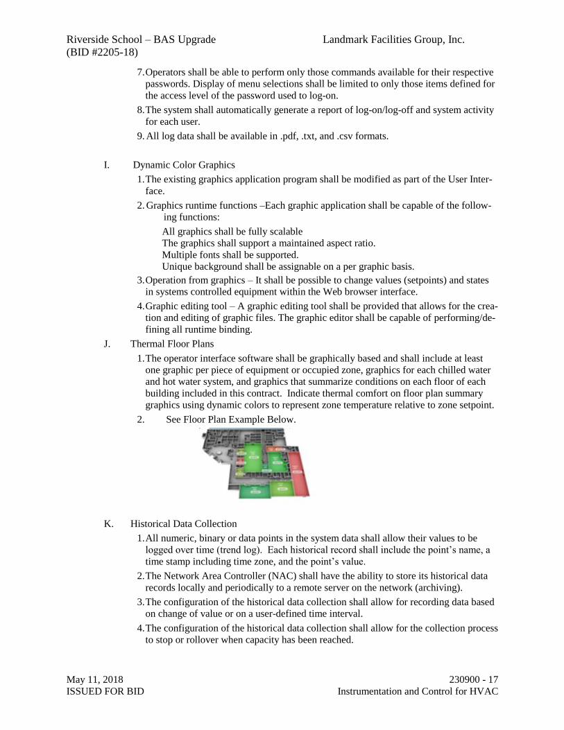
Riverside School – BAS Upgrade Landmark Facilities Group, Inc.
(BID #2205-18)
May 11, 2018 230900 - 17
ISSUED FOR BID Instrumentation and Control for HVAC
7. Operators shall be able to perform only those commands available for their respective
passwords. Display of menu selections shall be limited to only those items defined for
the access level of the password used to log-on.
8. The system shall automatically generate a report of log-on/log-off and system activity
for each user.
9. All log data shall be available in .pdf, .txt, and .csv formats.
I. Dynamic Color Graphics
1. The existing graphics application program shall be modified as part of the User Inter-
face.
2. Graphics runtime functions –Each graphic application shall be capable of the follow-
ing functions:
All graphics shall be fully scalable
The graphics shall support a maintained aspect ratio.
Multiple fonts shall be supported.
Unique background shall be assignable on a per graphic basis.
3. Operation from graphics – It shall be possible to change values (setpoints) and states
in systems controlled equipment within the Web browser interface.
4. Graphic editing tool – A graphic editing tool shall be provided that allows for the crea-
tion and editing of graphic files. The graphic editor shall be capable of performing/de-
fining all runtime binding.
J. Thermal Floor Plans
1. The operator interface software shall be graphically based and shall include at least
one graphic per piece of equipment or occupied zone, graphics for each chilled water
and hot water system, and graphics that summarize conditions on each floor of each
building included in this contract. Indicate thermal comfort on floor plan summary
graphics using dynamic colors to represent zone temperature relative to zone setpoint.
2. See Floor Plan Example Below.
K. Historical Data Collection
1. All numeric, binary or data points in the system data shall allow their values to be
logged over time (trend log). Each historical record shall include the point’s name, a
time stamp including time zone, and the point’s value.
2. The Network Area Controller (NAC) shall have the ability to store its historical data
records locally and periodically to a remote server on the network (archiving).
3. The configuration of the historical data collection shall allow for recording data based
on change of value or on a user-defined time interval.
4. The configuration of the historical data collection shall allow for the collection process
to stop or rollover when capacity has been reached.
Riverside School – BAS Upgrade Landmark Facilities Group, Inc.
(BID #2205-18)
May 11, 2018 230900 - 18
ISSUED FOR BID Instrumentation and Control for HVAC
5. A historical data viewing utility shall be provided with access to all history records.
This utility shall allow historical data to be viewed in a table or chart format.
6. The history data table view shall allow the user to hide/show columns and to filter data
based on time and date. The history data table shall allow exporting to .txt, .csv, or
.pdf file formats.
7. The historical data chart view shall allow different point histories to be displayed sim-
ultaneously, and also provide panning and zooming capabilities.
L. Audit Log
1. For each log entry, provide the following data;
Time and date
User ID
Change or activity: i.e., Change setpoint, add or delete objects, commands, etc.
M. Database Backup and Storage
1. The user shall have the ability to backup the System Controller databases.
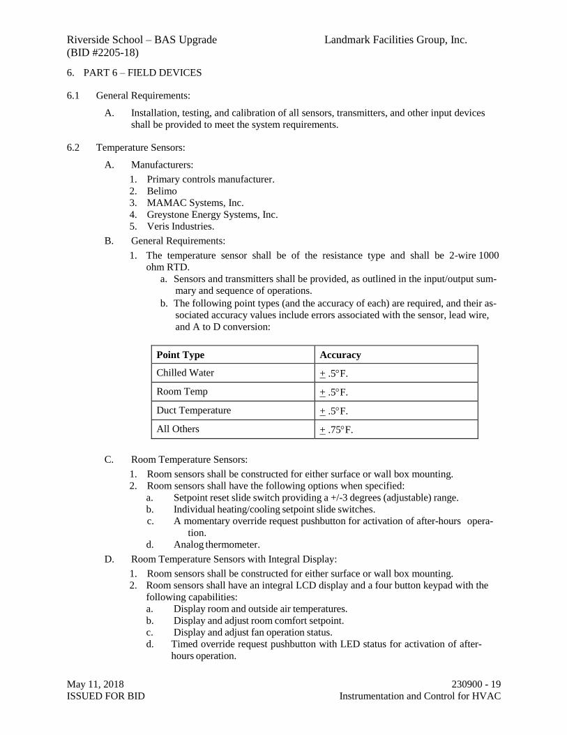
Riverside School – BAS Upgrade Landmark Facilities Group, Inc.
(BID #2205-18)
May 11, 2018 230900 - 19
ISSUED FOR BID Instrumentation and Control for HVAC
6. PART 6 – FIELD DEVICES
6.1 General Requirements:
A. Installation, testing, and calibration of all sensors, transmitters, and other input devices
shall be provided to meet the system requirements.
6.2 Temperature Sensors:
A. Manufacturers:
1. Primary controls manufacturer.
2. Belimo
3. MAMAC Systems, Inc.
4. Greystone Energy Systems, Inc.
5. Veris Industries.
B. General Requirements:
1. The temperature sensor shall be of the resistance type and shall be 2-wire 1000
ohm RTD.
a. Sensors and transmitters shall be provided, as outlined in the input/output sum-
mary and sequence of operations.
b. The following point types (and the accuracy of each) are required, and their as-
sociated accuracy values include errors associated with the sensor, lead wire,
and A to D conversion:
Point Type Accuracy
Chilled Water + .5F.
Room Temp + .5F.
Duct Temperature + .5F.
All Others + .75F.
C. Room Temperature Sensors:
1. Room sensors shall be constructed for either surface or wall box mounting.
2. Room sensors shall have the following options when specified:
a. Setpoint reset slide switch providing a +/-3 degrees (adjustable) range.
b. Individual heating/cooling setpoint slide switches.
c. A momentary override request pushbutton for activation of after-hours opera-
tion.
d. Analog thermometer.
D. Room Temperature Sensors with Integral Display:
1. Room sensors shall be constructed for either surface or wall box mounting.
2. Room sensors shall have an integral LCD display and a four button keypad with the
following capabilities:
a. Display room and outside air temperatures.
b. Display and adjust room comfort setpoint.
c. Display and adjust fan operation status.
d. Timed override request pushbutton with LED status for activation of after-
hours operation.

Riverside School – BAS Upgrade Landmark Facilities Group, Inc.
(BID #2205-18)
May 11, 2018 230900 - 20
ISSUED FOR BID Instrumentation and Control for HVAC
e. Display controller mode.
f. Password selectable adjustment of setpoint and override modes.
E. Thermo Wells:
1. Thermo wells shall be pressure-rated and constructed in accordance with the system
working pressure.
2. Thermo wells and sensors shall be mounted in a threadolet or 1/2" NFT saddle and
allow easy access to the sensor for repair or replacement.
F. Outside Air Sensors:
1. Outside air sensors shall be designed to withstand the environmental conditions to
which they will be exposed. They shall also be provided with a solar shield.
2. Sensors exposed to wind velocity pressures shall be shielded by a perforated plate that
surrounds the sensor element.
3. Temperature transmitters shall be of NEMA 3R construction and rated for ambient
temperatures.
G. Duct Mount Sensors:
1. Duct mount sensors shall mount in an electrical box through a hole in the duct, and be
positioned so as to be easily accessible for repair or replacement.
2. Duct sensors shall be insertion type and constructed as a complete assembly, including
lock nut and mounting plate.
3. For outdoor air duct applications, a weatherproof mounting box with weatherproof
cover and gasket shall be used.
H. Averaging Sensors:
1. For ductwork greater in any dimension than 48 inches and/or where air temperature
stratification exists, an averaging sensor with multiple sensing points shall be used.
2. For plenum applications, such as mixed air temperature measurements, a string of sen-
sors mounted across the plenum shall be used to account for stratification and/or air
turbulence. The averaging string shall have a minimum of four sensing points per 12
ft. long segment.
3. Capillary supports at the sides of the duct shall be provided to support the sensing
string.
6.3 Humidity Sensors:
A. Manufacturers:
1. Primary controls manufacturer.
2. MAMAC Systems, Inc.
3. Belimo
4. Greystone Energy Systems, Inc.
5. Veris Industries.
B. The sensor shall be a solid-state type, relative humidity sensor of the bulk polymer design.
The sensor element shall resist service contamination.
C. The humidity transmitter shall be equipped with non-interactive span and zero adjust-
ments, a 2-wire isolated loop powered 4-20 mA, 0-100% linear proportional output.
D. The humidity transmitter shall meet the following overall accuracy, including lead loss
and analog to digital conversion. Three percent between 20% and 80% RH at 77 deg F un-
less specified elsewhere.
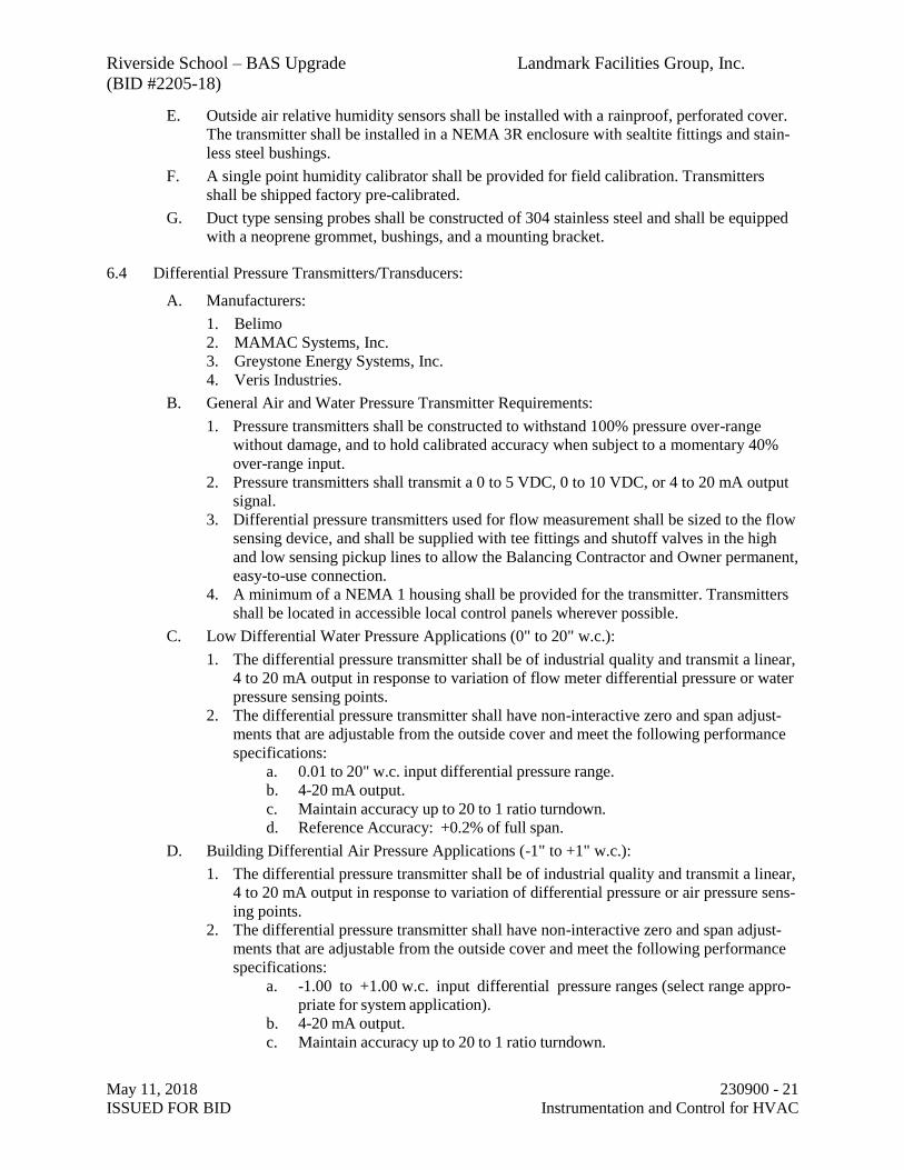
Riverside School – BAS Upgrade Landmark Facilities Group, Inc.
(BID #2205-18)
May 11, 2018 230900 - 21
ISSUED FOR BID Instrumentation and Control for HVAC
E. Outside air relative humidity sensors shall be installed with a rainproof, perforated cover.
The transmitter shall be installed in a NEMA 3R enclosure with sealtite fittings and stain-
less steel bushings.
F. A single point humidity calibrator shall be provided for field calibration. Transmitters
shall be shipped factory pre-calibrated.
G. Duct type sensing probes shall be constructed of 304 stainless steel and shall be equipped
with a neoprene grommet, bushings, and a mounting bracket.
6.4 Differential Pressure Transmitters/Transducers:
A. Manufacturers:
1. Belimo
2. MAMAC Systems, Inc.
3. Greystone Energy Systems, Inc.
4. Veris Industries.
B. General Air and Water Pressure Transmitter Requirements:
1. Pressure transmitters shall be constructed to withstand 100% pressure over-range
without damage, and to hold calibrated accuracy when subject to a momentary 40%
over-range input.
2. Pressure transmitters shall transmit a 0 to 5 VDC, 0 to 10 VDC, or 4 to 20 mA output
signal.
3. Differential pressure transmitters used for flow measurement shall be sized to the flow
sensing device, and shall be supplied with tee fittings and shutoff valves in the high
and low sensing pickup lines to allow the Balancing Contractor and Owner permanent,
easy-to-use connection.
4. A minimum of a NEMA 1 housing shall be provided for the transmitter. Transmitters
shall be located in accessible local control panels wherever possible.
C. Low Differential Water Pressure Applications (0" to 20" w.c.):
1. The differential pressure transmitter shall be of industrial quality and transmit a linear,
4 to 20 mA output in response to variation of flow meter differential pressure or water
pressure sensing points.
2. The differential pressure transmitter shall have non-interactive zero and span adjust-
ments that are adjustable from the outside cover and meet the following performance
specifications:
a. 0.01 to 20" w.c. input differential pressure range.
b. 4-20 mA output.
c. Maintain accuracy up to 20 to 1 ratio turndown.
d. Reference Accuracy: +0.2% of full span.
D. Building Differential Air Pressure Applications (-1" to +1" w.c.):
1. The differential pressure transmitter shall be of industrial quality and transmit a linear,
4 to 20 mA output in response to variation of differential pressure or air pressure sens-
ing points.
2. The differential pressure transmitter shall have non-interactive zero and span adjust-
ments that are adjustable from the outside cover and meet the following performance
specifications:
a. -1.00 to +1.00 w.c. input differential pressure ranges (select range appro-
priate for system application).
b. 4-20 mA output.
c. Maintain accuracy up to 20 to 1 ratio turndown.

Riverside School – BAS Upgrade Landmark Facilities Group, Inc.
(BID #2205-18)
May 11, 2018 230900 - 22
ISSUED FOR BID Instrumentation and Control for HVAC
d. Reference Accuracy: +0.2% of full span.
E. Low Differential Air Pressure Applications (0" to 5" w.c.):
1. The differential pressure transmitter shall be of industrial quality and transmit a linear,
4 to 20 mA output in response to variation of differential pressure or air pressure sens-
ing points.
2. The differential pressure transmitter shall have non-interactive zero and span adjust-
ments that are adjustable from the outside cover and meet the following performance
specifications:
a. 0.00 - 1.00" to 5.00" w.c. input differential pressure ranges (select range
appropriate for system application).
b. 4-20 mA output.
c. Maintain accuracy up to 20 to 1 ratio turndown.
d. Reference Accuracy: +0.2% of full span.
6.5 Gas Detectors
A. Manufacturers:
1. Primary Controls Manufacturer
2. MSA Inc.
3. TSI Incorporated.
4. Greystone Energy Systems, Inc.
5. Vulcan - Honeywell International Inc.
B. The detector shall include a sensor or sensors connected to a control panel. Each distinct
type of gas detection shall have a separate control panel. The control panel shall enable
communication through its BACnet output using BACnet/IP protocol over twisted-pair
Ethernet (10BaseT).
C. A self-test function allows for the activation/deactivation of all programmed outputs by
simulating a continuous 5% increase/decrease value until the maximum/minimum value is
reached.
D. A real-time clock enables operation of the outputs for a specific timeframe.
E. Manufacture to UL 1244 label and CSA 22.2.
F. Carbon Dioxide Transmitters:
1. Resolution Level: 1 ppm.
2. Resolution Range: 0-2000 ppm.
3. First Alarm: 850 ppm.
4. Second Alarm: 1500 ppm.
5. Mounting Height: 5 ft.
G. Effective Radius: 20 ft.
1. Temperature Range: -10 to 100 deg F.
2. Duct or wall mount as indicated.
3. Outputs: BACnet, RS485, DPDT.
H. Carbon Monoxide Transmitters:
1. Resolution Level: 1 ppm.
2. Resolution Range: 0-2000 ppm.
3. First Alarm: 25 ppm.
4. Second Alarm: 200 ppm.
5. Mounting Height: 3-5 ft.
6. Effective Radius: 50 ft.
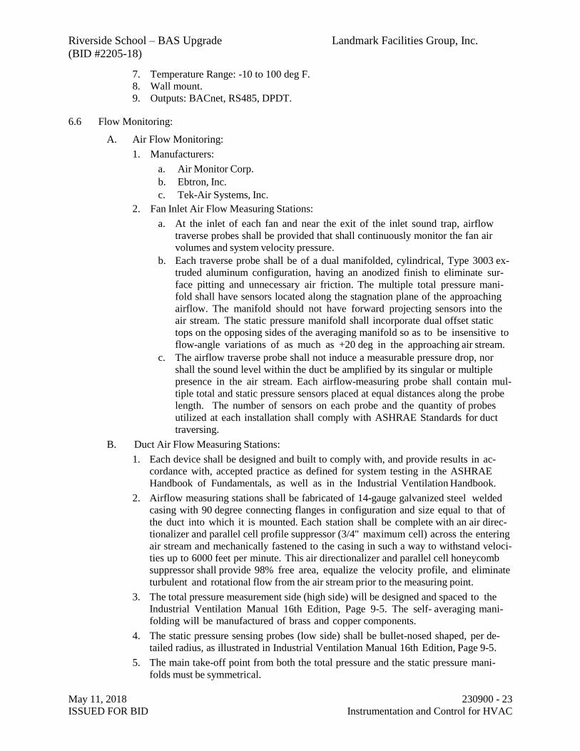
Riverside School – BAS Upgrade Landmark Facilities Group, Inc.
(BID #2205-18)
May 11, 2018 230900 - 23
ISSUED FOR BID Instrumentation and Control for HVAC
7. Temperature Range: -10 to 100 deg F.
8. Wall mount.
9. Outputs: BACnet, RS485, DPDT.
6.6 Flow Monitoring:
A. Air Flow Monitoring:
1. Manufacturers:
a. Air Monitor Corp.
b. Ebtron, Inc.
c. Tek-Air Systems, Inc.
2. Fan Inlet Air Flow Measuring Stations:
a. At the inlet of each fan and near the exit of the inlet sound trap, airflow
traverse probes shall be provided that shall continuously monitor the fan air
volumes and system velocity pressure.
b. Each traverse probe shall be of a dual manifolded, cylindrical, Type 3003 ex-
truded aluminum configuration, having an anodized finish to eliminate sur-
face pitting and unnecessary air friction. The multiple total pressure mani-
fold shall have sensors located along the stagnation plane of the approaching
airflow. The manifold should not have forward projecting sensors into the
air stream. The static pressure manifold shall incorporate dual offset static
tops on the opposing sides of the averaging manifold so as to be insensitive to
flow-angle variations of as much as +20 deg in the approaching air stream.
c. The airflow traverse probe shall not induce a measurable pressure drop, nor
shall the sound level within the duct be amplified by its singular or multiple
presence in the air stream. Each airflow-measuring probe shall contain mul-
tiple total and static pressure sensors placed at equal distances along the probe
length. The number of sensors on each probe and the quantity of probes
utilized at each installation shall comply with ASHRAE Standards for duct
traversing.
B. Duct Air Flow Measuring Stations:
1. Each device shall be designed and built to comply with, and provide results in ac-
cordance with, accepted practice as defined for system testing in the ASHRAE
Handbook of Fundamentals, as well as in the Industrial Ventilation Handbook.
2. Airflow measuring stations shall be fabricated of 14-gauge galvanized steel welded
casing with 90 degree connecting flanges in configuration and size equal to that of
the duct into which it is mounted. Each station shall be complete with an air direc-
tionalizer and parallel cell profile suppressor (3/4" maximum cell) across the entering
air stream and mechanically fastened to the casing in such a way to withstand veloci-
ties up to 6000 feet per minute. This air directionalizer and parallel cell honeycomb
suppressor shall provide 98% free area, equalize the velocity profile, and eliminate
turbulent and rotational flow from the air stream prior to the measuring point.
3. The total pressure measurement side (high side) will be designed and spaced to the
Industrial Ventilation Manual 16th Edition, Page 9-5. The self- averaging mani-
folding will be manufactured of brass and copper components.
4. The static pressure sensing probes (low side) shall be bullet-nosed shaped, per de-
tailed radius, as illustrated in Industrial Ventilation Manual 16th Edition, Page 9-5.
5. The main take-off point from both the total pressure and the static pressure mani-
folds must be symmetrical.
Riverside School – BAS Upgrade Landmark Facilities Group, Inc.
(BID #2205-18)
May 11, 2018 230900 - 24
ISSUED FOR BID Instrumentation and Control for HVAC
6. Total and static pressure manifolds shall terminate with external ports for connec-
tion to control tubing. An identification label shall be placed on each unit casing, list-
ing model number, size, area, and specified airflow capacity.
7. Installation Considerations:
a. The maximum allowable pressure loss through the flow and static pressure
elements shall not exceed .065" w.c. at 1000 feet per minute, or .23" w.c. at
2000 feet per minute. Each unit shall measure the airflow rate within an ac-
curacy of plus 2% as determined by U.S. – GSA certification tests, and shall
contain a minimum of one total pressure sensor per 36 square inches of unit
measuring area.
b. The units shall have a self-generated sound rating of less than NC40, and the
sound level within the duct shall not be amplified nor shall additional sound
be generated.
c. Where the stations are installed in insulated ducts, the airflow passage of the sta-
tion shall be the same size as the inside airflow dimension of the duct. Station
flanges shall be two inch to three inch to facilitate matching connecting duct-
work.
d. Where control dampers are shown as part of the airflow measuring station,
opposed blade precision controlled volume dampers integral to the station and
complete with actuator, pilot positioner, and linkage shall be provided.
e. e) Stations shall be installed in strict accordance with the manufacturer’s pub-
lished requirements, and in accordance with ASME Guidelines affecting non-
standard approach conditions.
C. Static Pressure Traverse Probe:
1. Manufacturers:
a. Ebtron, Inc.
b. MAMAC Systems, Inc.
c. Veris Industries.
2. The probe shall contain multiple static pressure sensors located along the exterior
surface of the cylindrical probe.
3. Size: 75% of duct width.
D. Shielded Static Air Probe:
1. Manufacturers:
a. Ebtron, Inc.
b. MAMAC Systems, Inc.
c. Veris Industries.
2. The probe shall have multiple sensing ports, an impulse suppression chamber, and air-
flow shielding. A suitable probe for indoor and outdoor locations shall be provided.
E. Water Flow Monitoring:
1. Manufacturers:
a. Belimo
b. Badger Meter.
c. EMCO Flow Systems; Division of Advanced Energy Company.
d. Onicon, Inc.
e. Rosemount, Emerson Process Controls.
f. Spirax Sarco, Inc.
g. Veris Industries.

Riverside School – BAS Upgrade Landmark Facilities Group, Inc.
(BID #2205-18)
May 11, 2018 230900 - 25
ISSUED FOR BID Instrumentation and Control for HVAC
2. Liquid Flow Meters:
a. Sensing: Electromagnetic.
b. Converter: Integral microprocessor-based. 3)
c. Accuracy: +/- 0.2%.
d. ANSI Class: 150 or 300 to match piping system.
e. Maximum Temperature: 302 deg F.
f. Material: Epoxy-coated steel tube with stainless steel probes.
g. Output: 4-20 mA, programmable pulse.
h. Input: Keypad.
6.7 Power Monitoring Devices:
A. Current Measurement (amps):
1. Manufacturers:
a. ACI
b. Setra Systems, Inc.
c. Veris Industries.
2. Current measurement shall be by a combination current transformer and a current
transducer. The current transformer shall be sized to reduce the full amperage of the
monitored circuit to a maximum 5 amp signal, which will be converted to a 4-20
mA DDC compatible signal for use by the Facility Management System.
B. Current Transformer: A split core current transformer shall be provided to monitor motor
amps.
1. Operating Frequency: 50 to 400 Hz.
2. Insulation: 0.6 kV Class 10Kv BIL.
3. UL recognized.
4. Five amp secondary.
5. Select current ration as appropriate for application.
C. Current Transducer: A current to voltage or current to mA transducer shall be pro-
vided. The current transducer shall include:
1. 6X input over amp rating for AC inrushes of up to 120 amps.
2. Manufactured to UL 1244.
3. Accuracy: +.5%, ripple +1%.
4. Minimum Load Resistance: 30 kOhm.
5. Input: 0-20 amps.
6. Output: 4-20 mA.
7. Transducer shall be powered by a 24 Vdc regulated power supply (24 Vdc+5%).
6.8 Status and Safety Switches:
A. General Requirements:
1. Switches shall be provided to monitor equipment status, safety conditions, and
generate alarms at the BMS when a failure or abnormal condition occurs. Safety
switches shall be provided with two sets of contacts and shall be interlock wired to
shut down respective equipment.
B. Current Sensing Switches:
1. Manufacturers:
a. ACI
b. Setra Systems, Inc.

Riverside School – BAS Upgrade Landmark Facilities Group, Inc.
(BID #2205-18)
May 11, 2018 230900 - 26
ISSUED FOR BID Instrumentation and Control for HVAC
c. Veris Industries.
2. The current sensing switch shall be self-powered with solid-state circuitry and a dry
contact output. It shall consist of a current transformer, a solid state current sensing
circuit, adjustable trip point, solid-state switch, SPDT relay, and an LED indicating
the on or off status. A conductor of the load shall be passed through the window of
the device. It shall accept over-current up to twice its trip point range.
3. Current sensing switches shall be used for run status for fans, pumps, and other
miscellaneous motor loads.
4. Current sensing switches shall be calibrated to show a positive run status only
when the motor is operating under load. A motor running with a broken belt or
coupling shall indicate a negative run status.
C. Air Filter Status Switches:
1. Differential pressure switches used to monitor air filter status shall be of the au-
tomatic reset type with SPDT contacts rated for 2 amps at 120 Vac.
2. A complete installation kit shall be provided, including static pressure tops, tubing, fit-
tings, and air filters.
3. Provide appropriate scale range and differential adjustment for intended service.
D. Air Flow Switches:
1. Differential pressure flow switches shall be bellows actuated mercury switches or
snap acting micro-switches with appropriate scale range and differential adjustment
for intended service.
E. Air Pressure Safety Switches:
1. Air pressure safety switches shall be of the manual reset type with SPDT contacts
rated for 2 amps at 120 Vac.
2. Pressure range shall be adjustable with appropriate scale range and differential ad-
justment for intended service.
F. Low Temperature Limit (Freeze) Switches:
1. The low temperature limit switch shall be of the manual reset type with double
pole/single throw snap acting contacts rated for 16 amps at 120 Vac.
2. The sensing element shall be a minimum of 15 feet in length and shall react to the
coldest 18-inch section. Element shall be mounted horizontally across duct in ac-
cordance with manufacturer's recommended installation procedures.
3. For large duct areas where the sensing element does not provide full coverage of the
air stream, additional switches shall be provided as required to provide full protec-
tion of the air stream.
7. MISCELLANEOUS DEVICES
7.1 Local Control Panels:
A. All control panels shall be factory constructed, incorporating the BAS manufacturer’s
standard designs and layouts. All control panels shall be UL inspected and listed as an
assembly and carry a UL 508 label listing compliance. Control panels shall be fully
enclosed, with perforated sub-panel, hinged door and slotted flush latch.
B. In general, the control panels shall consist of the DDC controller(s), display module as
specified and indicated on the plans, and I/O devices such as relays, transducers, and so
forth that are not required to be located external to the control panel due to function.
Where specified the display module shall be flush-mounted in the panel face unless
otherwise noted.

Riverside School – BAS Upgrade Landmark Facilities Group, Inc.
(BID #2205-18)
May 11, 2018 230900 - 27
ISSUED FOR BID Instrumentation and Control for HVAC
C. All I/O connections on the DDC controller shall be provided via removable or fixed
screw terminals.
D. Low and line voltage wiring shall be segregated. All provided terminal strips and wiring
shall be UL listed, 300 volt service and provide adequate clearance for field wiring.
E. All wiring shall be neatly installed in plastic trays or tie-wrapped.
F. A convenience 120 Vac duplex receptacle shall be provided in each enclosure, fused
on/off power switch, and required transformers.
7.2 Power Supplies:
A. DC power supplies shall be sized for the connected device load. Total rated load shall
not exceed 75% of the rated capacity of the power supply.
B. Input: 120 Vac +10%, 60 Hz.
C. Output: 24 Vdc.
D. Line Regulation: +0.05% for 10% line change.
E. Load Regulation: +0.05% for 50% load change.
F. Ripple and Noise: 1 mV rms, 5 mV peak to peak.
G. An appropriately sized fuse and fuse block shall be provided and located next to the
power supply.
H. A power disconnect switch shall be provided next to the power supply.
7 . 3 Boiler Emergency Switches:
A. Provide pre-printed boiler emergency faceplate and gray switch handle. Provide interior
switches with Lexan cover with 9 volt battery powered 95
8. PART 3 - EXECUTION
8.1 BAS SPECIFIC REQUIREMENTS
A. Graphic Displays
1. Provide a color graphic system flow diagram display for each system with all points as
indicated on the point list. At a minimum the contractor shall insure there are graphics
depicting building floor plans, all central panels, boiler rooms, zone control, and ani-
mated 3-dimensional graphics for each unit ventilator, air handler, fan coil, etc..
2. User shall access the various system schematics via a graphical penetration scheme
and/or menu selection. .
B. Actuation / Control Type
1. Unit Mounted Equipment
a. Where control devices are indicated to be unit mounted, the BAS Contractor
shall supply and ship all DDC controllers, relays, transformers, valves and
damper actuators to the unit equipment manufacturer for mounting and wiring.
The unit manufacturer shall mount and wire the controllers as per the BAS
Contractor’s control wiring diagrams and instructions.
b. All damper and valve actuation shall be electric, spring return fail-safe and nor-
mally open or closed as specified herein.
2. Air Handling Equipment
Riverside School – BAS Upgrade Landmark Facilities Group, Inc.
(BID #2205-18)
May 11, 2018 230900 - 28
ISSUED FOR BID Instrumentation and Control for HVAC
a. All new Air Handling Equipment shall be 100% DDC controlled.
b. All damper and valve actuation shall be electric.
8.2 INSTALLATION PRACTICES
A. BAS Wiring
1. All conduit, wiring, accessories and wiring connections required for the installation of
the Building Automation System, as herein specified, shall be provided by the BAS
Contractor unless specifically shown on the Electrical Drawings under Division 26
Electrical. All wiring shall comply with the requirements of applicable portions of
Division 26 and all local and national electric codes, unless specified otherwise in this
section.
2. All BAS wiring materials and installation methods without exception are to comply
with the following BAS manufacturers recommended installation standards.
a. All Analog Input, Analog Output, Binary Input, Binary Output and 24VAC con-
trol cables shall be UL Plenum Rated and color coded as follows; Analog Input
Cable – Yellow Jacket, Analog Output Cable – Tan Jacket, Binary Input Cable –
Orange Jacket, Binary Output Cable – Violet Jacket, 24VAC Cable – Grey
Jacket.
b. All Field Bus and Ethernet LAN communications cables shall be UL Plenum
Rated and be color coded as follows; Field Bus – Blue Jacket with Yellow
Stripe, Ethernet LAN Cable – Violet Jacket.
c. All Ethernet LAN communications cable be UL Plenum Rated and shall meet
or exceed Category 6 rating.
3. The sizing, type and provision of cable, conduit, cable trays, and raceways shall be the
design responsibility of the BAS Contractor. If complications arise, however, due to
the incorrect selection of cable, cable trays, raceways and/or conduit by the BAS Con-
tractor, the Contractor shall be responsible for all costs incurred in replacing the se-
lected components.
4. Class 2 Wiring
a. All Class 2 (24VAC or less) wiring shall be installed in conduit unless other-
wise specified.
b. Conduit is not required for Class 2 wiring in concealed accessible locations.
Class 2 wiring not installed in conduit shall be supported every 5’ from the
building structure utilizing metal hangers designed for this application. Wiring
shall be installed parallel to the building structural lines. All wiring shall be
installed in accordance with local code requirements.
c. Class 2 signal wiring and 24VAC power can be run in the same conduit. Power
wiring 120VAC and greater cannot share the same conduit with Class 2 signal
wiring.
d. Provide for complete grounding of all applicable signal and communications
cables, panels and equipment so as to ensure system integrity of operation.
Ground cabling and conduit at the panel terminations. Avoid grounding loops.
B. BAS Line Voltage Power Source
1. 120-volt AC circuits used for the Building Automation System shall be taken from
panel boards and circuit breakers provided by Division 26.

Riverside School – BAS Upgrade Landmark Facilities Group, Inc.
(BID #2205-18)
May 11, 2018 230900 - 29
ISSUED FOR BID Instrumentation and Control for HVAC
2. Circuits used for the BAS shall be dedicated to the BAS and shall not be used for any
other purposes.
3. DDC terminal unit controllers may use AC power from motor power circuits.
C. BAS Raceway
1. All cables to be open plenum rated with EMT in exposed areas.
2. Where it is not possible to conceal raceways in finished locations, surface raceway
(Wiremold) may be used as approved by the Architect.
3. All conduits and raceways shall be installed level, plumb, at right angles to the build-
ing lines and shall follow the contours of the surface to which they are attached.
4. Flexible Metal Conduit shall be used for vibration isolation and shall be limited to 3
feet in length when terminating to vibrating equipment. Flexible Metal Conduit may
be used within partition walls. Flexible Metal Conduit shall be UL listed.
D. Penetrations
1. Provide fire stopping for all penetrations used by dedicated BAS conduits and race-
ways.
2. All openings in fire proofed or fire stopped components shall be closed by using ap-
proved fire resistive sealant.
3. All wiring passing through penetrations, including walls shall be in conduit or en-
closed raceway.
4. Penetrations of floor slabs shall be by core drilling. All penetrations shall be plumb,
true, and square.
E. BAS Identification Standards
1. Node Identification. All nodes shall be identified by a permanent label fastened to the
enclosure. Labels shall be suitable for the node location. Cable types specified in Item
A shall be color coded for easy identification and troubleshooting.
F. BAS Panel Installation
1. The BAS panels and cabinets shall be located as indicated at an elevation of not less
than 2 feet from the bottom edge of the panel to the finished floor. Each cabinet shall
be anchored per the manufacturer’s recommendations.
2. The BAS contractor shall be responsible for coordinating panel locations with other
trades and electrical and mechanical contractors.
G. Input Devices
1. All Input devices shall be installed per the manufacturer recommendation
2. Locate components of the BAS in accessible local control panels wherever possible.
H. HVAC Input Devices – Genera1
1. All Input devices shall be installed per the manufacturer recommendation
2. Locate components of the BAS in accessible local control panels wherever possible.
3. The mechanical contractor shall install all in-line devices such as temperature wells,
pressure taps, airflow stations, etc.
4. Input Flow Measuring Devices shall be installed in strict compliance with ASME
guidelines affecting non-standard approach conditions.
5. Outside Air Sensors
Riverside School – BAS Upgrade Landmark Facilities Group, Inc.
(BID #2205-18)
May 11, 2018 230900 - 30
ISSUED FOR BID Instrumentation and Control for HVAC
a. Sensors shall be mounted on the North wall to minimize solar radiant heat im-
pact or located in a continuous intake flow adequate to monitor outside air con-
ditions accurately.
b. Sensors shall be installed with a rain proof, perforated cover.
6. Water Differential Pressure Sensors
a. Differential pressure transmitters used for flow measurement shall be sized to
the flow-sensing device.
b. Differential pressure transmitters shall be supplied with tee fittings and shut-
off valves in the high and low sensing pick-up lines.
c. The transmitters shall be installed in an accessible location wherever possible.
7. Duct Temperature Sensors:
a. Duct mount sensors shall mount in an electrical box through a hole in the duct
and be positioned so as to be easily accessible for repair or replacement.
b. The sensors shall be insertion type and constructed as a complete assembly in-
cluding lock nut and mounting plate.
c. For ductwork greater in any dimension than 48 inches or where air temperature
stratification exists such as a mixed air plenum, utilize an averaging sensor.
d. The sensor shall be mounted to suitable supports using factory approved ele-
ment holders.
8. Space Sensors:
a. Shall be mounted per ADA requirements.
b. Provide lockable tamper-proof covers in public areas and/or where indicated on
the plans.
9. Low Temperature Limit Switches:
a. Install on the discharge side of the first water or steam coil in the air stream.
b. Mount element horizontally across duct in a serpentine pattern insuring each
square foot of coil is protected by 1 foot of sensor.
c. For large duct areas where the sensing element does not provide full coverage
of the air stream, provide additional switches as required to provide full protec-
tion of the air stream.
10. Air Differential Pressure Status Switches:
a. Install with static pressure tips, tubing, fittings, and air filter.
11. Water Differential Pressure Status Switches:
a. Install with shut off valves for isolation.
I. HVAC Output Devices
1. All output devices shall be installed per the manufacturer’s recommendation. The me-
chanical contractor shall install all in-line devices such as control valves, dampers, air-
flow stations, pressure wells, etc.
2. Actuators: All control actuators shall be sized capable of closing against the maxi-
mum system shut-off pressure. The actuator shall modulate in a smooth fashion
through the entire stroke. When any pneumatic actuator is sequenced with another
device, pilot positioners shall be installed to allow for proper sequencing.
3. Control Dampers: Shall be opposed blade for modulating control of airflow. Parallel
blade dampers shall be installed for two position applications.

Riverside School – BAS Upgrade Landmark Facilities Group, Inc.
(BID #2205-18)
May 11, 2018 230900 - 31
ISSUED FOR BID Instrumentation and Control for HVAC
4. Control Valves: Shall be sized for proper flow control with equal percentage valve
plugs. The maximum pressure drop for water applications shall be 5 PSI. The maxi-
mum pressure drop for steam applications shall be 2 PSI.
8.3 SCHEDULE OF RESPONSIBILITIES
A. The following schedule identifies the responsible Division for the installation of the building
automation system. This schedule should be used as a general guide. The General Contractor
is the central authority governing the total responsibility of all trade contractors. Therefore,
deviations and clarifications of this schedule are permitted provided the General Contractor
assumes responsibility to coordinate the trade contractors different than as indicated herein. If
deviations or clarifications to this schedule are implemented, submit a record copy to the Ar-
chitect.
Item Furnish
By
Install
By
Power
By
Control
Wiring By
1. Equipment Motors M M E
2. Magnetic Motor Starters:
a. Automatically controlled,
with or without HOA
switches.
E E E E
b. Manually controlled. E E E
c. Manually controlled, and
which are furnished as part
of factory wired equipment.
M M E E
d. Special duty type (part
winding, multi-speed, etc.)
M See Note
1.
E See Note 1.
e. Variable frequency drives
with manual bypass.
SI M E SI
See Note 2.
f. Domestic booster pump.
Motor Controls
M M E SI
5. General equipment disconnect switches, ther-
mal overload switches, manual operating
switches.
E E E
6. Sprinkler system water flow and tamper
switches.
M M E
7. Outside fire alarm horn and light (at Siamese
connection).
M M E
8. Line voltage contactors. E E E E
9. Control relay transformers (other than starters). SI SI E SI

Riverside School – BAS Upgrade Landmark Facilities Group, Inc.
(BID #2205-18)
May 11, 2018 230900 - 32
ISSUED FOR BID Instrumentation and Control for HVAC
Item Furnish
By
Install
By
Power
By
Control
Wiring By
10. Main fuel oil tank alarms (high and low level)
and remote indicating lights.
M M SI SI
11. Day tank fuel oil alarms (high and low level)
and remote indicating lights.
E E E SI
12. Line voltage control items such as line voltage
thermostats not connected to control panel sys-
tems.
M SI SI SI
13. Loose controls and instruments furnished as
part of the packaged mechanical equipment or
required for operation such as valves, float con-
trols, relays, sensors, etc.
M M E __
14. Control and Instrumentation panels SI SI E SI
15. Automatic control valves, automatic dampers
and damper operators, solenoid valves, inser-
tion temperature and pressure sensors.
SI M SI SI
17. Duct type fire and smoke detectors, including
relays for fan shut down.
M E E See Note 5.
18. Contactors for cooling tower basin heaters. M M E E
19. Mechanical piping heat tracing (including re-
lays, contactors, thermostats, etc.)
M M E E
20. Emergency power off (EPO) shut down
pushbutton(s) (break glass station) and con-
trols.
SI SI SI SI
21. Control interlock wiring or software bindings
between chillers, pumps and cooling towers,
fans and air handling units and other miscella-
neous mechanical equipment.
SI SI SI SI
23. Airflow control devices with transmitter. SI M SI SI
24. Air terminal devices (i.e., VAV and fan pow-
ered boxes).
M M E SI
25. Intelligent Devices and Control Units provided
with packaged mechanical equipment such as:
M M E SI
Valve and damper operators.
Heat pumps, AC units.
Fan Coil Units.

Riverside School – BAS Upgrade Landmark Facilities Group, Inc.
(BID #2205-18)
May 11, 2018 230900 - 33
ISSUED FOR BID Instrumentation and Control for HVAC
Item Furnish
By
Install
By
Power
By
Control
Wiring By
Air Terminal Units.
Boilers.
26. Intelligent Devices and Control Units provided
with electrical systems such as:
E E E SI
Occupancy/motion sensors.
Lighting Control Panels.
Switches and Dimmers.
Switch Multiplexing Control Units.
Door Entry Control Units.
27. Gateways or interfaces for protocol conversion
with a non-LONWORKS OR BACNET
based system.
M E E SI
28. Routers, Bridges and Repeaters. SI SI SI SI
Abbreviations
Furnish. Furnished by
Install. Installed by
Power Power Wiring Connection, Low and Medium Voltage
SI Systems Integrator (BAS Contractor)
M Mechanical Contractor
E Electrical Contractor
Notes to Schedule of Responsibilities:
1. Magnetic motor starters (special duty type) shall be set in place under electrical division
except when part of factory wired equipment, in which case set in place under mechani-
cal division.
2. Where a remote motor disconnect is required in addition to the one provided integral to an
Variable Frequency Drive (VFD), the NI Contractor shall provide the necessary control
interlock between the disconnects.
3. The System Integrator shall inform the Mechanical Contractor and the Electrical Contrac-
tor of the additional capacity required of control power transformers.
4. The Mechanical Contractor shall refer to the electrical specifications and plans for all
power and control wiring and shall advise the Architect of any discrepancies prior to bid-
ding. The System Integrator shall be responsible for all control wiring as outlined,
whether called for by the mechanical or electrical drawings and specifications.
5. Smoke Detectors and Dampers requiring interlock with building fire alarm system shall
be wired by Fire Alarm contractor. Mechanical contractor shall coordinate with Fire
Alarm contractor to ensure compatibility prior to order such devices.
Riverside School – BAS Upgrade Landmark Facilities Group, Inc.
(BID #2205-18)
May 11, 2018 230900 - 34
ISSUED FOR BID Instrumentation and Control for HVAC
6.4 DEMONSTRATION
A. Engage a factory-authorized service representative to train Owner's maintenance personnel to
adjust, operate, and maintain control systems and components.
1. Train Owner's maintenance personnel on procedures and schedules for starting and
stopping, troubleshooting, servicing, and maintaining equipment and schedules.
2. Provide operator training on data display, alarm and status descriptors, requesting data,
executing commands, calibrating and adjusting devices, resetting default values, and
requesting logs. Include a minimum of 40 hours' dedicated instructor time on-site.
3. Review data in maintenance manuals. Refer to Division 1 Sections "Contract Closeout" or
"Operation and Maintenance Data."
4. Schedule training with Owner, through Architect, with at least seven days' advance notice.
6.5 ON-SITE ASSISTANCE
A. Occupancy Adjustments: Within one year of date of Substantial Completion, provide up to three
Project site visits, when requested by Owner, to adjust and calibrate components and to assist
Owner's personnel in making program changes and in adjusting sensors and controls to suit actual
conditions.
END OF SECTION 15900
Riverside School – BAS Upgrade Landmark Facilities Group, Inc.
(BID #2205-18)
May 11, 2018 Sequence of Operation
ISSUED FOR BID 230993 - 1
SECTION 230993 – SEQUENCE OF OPERATION
PART 1 - GENERAL
1.1 RELATED DOCUMENTS
A. Drawings and general provisions of the Contract, including General and Supplementary
Conditions and Division 1 Specification Sections, apply to this Section.
1.2 SUMMARY
A. This Section includes control sequences for HVAC systems, subsystems, and equipment.
B. Related Sections include the following:
i. Division 15 Section "HVAC Instrumentation and Controls" for control equipment and
devices and submittal requirements.
1.3 SEQUENCE OF OPERATIONS – GENERAL
A. The Contractor shall review the following sequences of operations, points lists, and Controls
Drawings to ensure that all points, devices, and programming are included for proper operation
as outlined herein. Any points, devices, work, or controls mentioned in the sequences of
operations and/or shown on the Controls Drawings, but not listed on the points list, or vice versa,
shall be provided without additional expense to the Owner.
B. The BAS Contractor shall be responsible for full integration between the heating and cooling
plant, all associated piping and controls, and existing HVAC equipment identified for tie-in. This
includes, but is not limited to, all factory controls furnished by unitary equipment manufacturers.
BAS contractor shall identify features and capabilities of all factory controllers to ensure
successful communication and integration with their products and user interface.
C. With the exception of freeze protection thermostats, all temperature and humidity setpoints shall
be adjustable.
D. Lead/Lag Control: For all redundant water pumps, the control system shall:
i. Alternate operation of the equipment to maintain even wear
ii. Automatically start the lag equipment in the event the lead equipment fails.
1.4 DEFINITIONS
A. DDC: Direct-digital controls.
B. BAS: Building Automation System.

Riverside School – BAS Upgrade Landmark Facilities Group, Inc.
(BID #2205-18)
May 11, 2018 Sequence of Operation
ISSUED FOR BID 230993 - 2
1.5 GRAPHICAL USER INTERFACE (GUI)
A. Operator Workstation: Display the following data:
1. Dynamic system graphics.
2. Thermal floor plans.
3. Space temperature (cooling thermostat, ALL)
4. Space temperature (heating thermostat, ALL)
5. Boiler status and firing rate
6. Hot water pump status and speed.
7. Hot water control valve position (ALL).
8. Glycol concentration at refractometer.
9. WSHP fan status.
10. WSHP discharge air temp.
11. Unit heater fan status.
12. Unit heater discharge air temp.
13. Unit heater damper positions.
14. Condenser water pump status and speed.
15. Condenser water supply temperature.
16. Condenser water return temperature.
17. Condenser water valve position (ALL).
18. Cooling tower fan status.
19. Cooling tower fan speed.
20. Outside air temperature.
21. Outside air relative humidity.
22. Filter differential pressure (AHU-1).
B. Provide alarm limits for all temperature setpoints identified above. In addition, BAS shall pass
along all common alarms from equipment possessing dedicated microprocessor controls, such
as chillers, boilers, and VFDs. Common equipment alarms shall be accessible via dedicated
menu or tab at GUI.
1.6 MECHANICAL PLANT CONTROL
A. HOT WATER BOILERS
1. Boilers shall be enabled whenever hot water pump is running. System shall automatically
alternate lead boiler after 40 hrs of operation (adj.) for even run time. Motorized control valve
shall open and flow shall be proven before boiler is able to start. Boiler shall run to maintain hot
water supply temperature in accordance with outdoor air reset schedule. When boiler stops
firing, control valve shall close.
2. Hot water supply temperature shall be maintained in accordance with the following
schedule (adj.):
Riverside School – BAS Upgrade Landmark Facilities Group, Inc.
(BID #2205-18)
May 11, 2018 Sequence of Operation
ISSUED FOR BID 230993 - 3
B. HOT WATER PUMPS
1. Standby pump shall automatically start in the event tat lead pump fails to start. Alarm shall
be initiated at user interface.
2 Control system shall alternate lead pump designation every 40 hours of run time (adj,) to
maintain even wear.
3. Pump speed shall be varied to maintain (lower limit) differential pressure at DP sensor.
Motorized bypass valve shall open if loop differential pressure exceeds upper limit for 60 seconds.
C. COOLING TOWER CONTROL
1. Cooling tower fan staging and speed shall be controlled based on leaving condenser water
temperature measured at factory controller.
2. Cooling tower spray pump staging shall be controlled based on leaving condenser water
temperature measured at factory controller.
3. Cooling tower shall be enabled whenever condenser water pump is running.
D. CONDENSER WATER PUMP
1. At outside air temperatures of 60 deg F and above (adj.), condenser water pump shall run
at constant speed set by balance contractor. When outside air temperature falls below 60
deg F (adj.), pump shall stop.
1.7 AHU-1 CONTROL (GYM)
A. Supply and return fans shall run during occupied periods. Fans shall run only to maintain
Unoccupied heating setpoint during unoccupied periods.
B. When supply fan is running, outside air (OA) and exhaust air (EA) dampers shall open to
minimum position (set by ATB contractor). If indoor CO2 level exceeds upper limit (800 ppm
adjustable), outside air damper shall modulate to maintain indoor CO2 level below upper limit.
EA damper shall be sequenced with OA damper to maintain neutral space pressure.
C. OA and EA dampers shall be closed during unoccupied periods.
D. During a call for heat, hot water control valves shall modulate to maintain space thermostat
setpoint.
Riverside School – BAS Upgrade Landmark Facilities Group, Inc.
(BID #2205-18)
May 11, 2018 Sequence of Operation
ISSUED FOR BID 230993 - 4
E. Economizer Mode [applicable if Ductless Split Systems are integrated into BAS]: During a
call for cooling and when outdoor air dry bulb is below return air dry bulb temperature, unit
shall enter economizer mode. Ductless split systems shall remain off. Outdoor air damper
shall modulate to maintain space temperature cooling setpoint. Exhaust air damper shall be
sequenced with OA damper to maintain neutral space pressure.
F. When filter differential pressure exceeds upper limit, filter alarm shall be initiated at user
interface.
G. Deadband temperature shall be no less than 5 deg F.
H. Smoke observed at duct mounted smoke detector will stop supply and exhaust fans and close
OA damper. Alarm shall be initiated at Fire Alarm system.
1.8 CAFETERIA COOLING SYSTEM (RTU-1 & RTU-2)
A. Units shall enable at outdoor temperatures of 60 deg F and above (adj.)
B. Unit fan shall run continuously during Occupied periods. Outside air damper shall open to
preset minimum position when fan is running. During Unoccupied periods, fan shall run only
as required to maintain Unoccupied heating and cooling setpoints. OA damper shall close
when fan stops.
C. During a call for cooling, unit shall modulate compressor to maintain space cooling
temperature setpoint.
D. ECONOMIZER OPERATION: When outdoor air enthalpy is less than indoor air enthalpy,
Economizer mode shall be enabled. Unit shall modulate OA and RA dampers to maintain
space temperature setpoint.
E. Smoke observed at duct mounted smoke detector shall stop fan and close OA damper. Alarm
shall be initiated at Fire Alarm system.
1.9 WATER SOURCE HEAT PUMP CONTROL
A. During a call for cooling at thermostat, control valve shall open and WSHP fan and compressor
shall start and run to maintain cooling space temperature.
B. Deadband temperature (between heating and cooling thermostat setpoints) shall be no less than 4
deg F.
1.10 UNIT VENTILATOR CONTROL
Riverside School – BAS Upgrade Landmark Facilities Group, Inc.
(BID #2205-18)
May 11, 2018 Sequence of Operation
ISSUED FOR BID 230993 - 5
A. Unit ventilator fan shall run continuously during periods and stop during unoccupied periods.
Unit shall be enabled at outdoor temperatures below 60 deg F (adjustable) and can be manually
started/stopped at user interface
B. During a call for heat, hot water control valve shall open. Face and bypass dampers shall
modulate to maintain space temperature setpoint. Damper shall be controlled so as to limit
discharge air temperature to 140 deg F and below.
C. When fan is running, OA damper shall open to preset minimum position. OA damper shall close
when fan stops.
D. Fan shall stop and OA damper shall close when EAT is below 40 deg F. Alarm shall be initiated
at user interface. Unit shall not run until freezestat alarm is manually reset.
1.11 PERIMETER RADIATION CONTROL
A. During a call for heat, hot water control valve shall modulate to maintain space temperature
setpoint. Control valve shall close when space temp setpoint is satisfied.

Riverside School – BAS Upgrade Landmark Facilities Group, Inc.
(BID #2205-18)
May 11, 2018 Low-voltage Electrical Power Conductors And Cables
ISSUED FOR BID 260519 - 1
SECTION 260519
LOW-VOLTAGE ELECTRICAL POWER CONDUCTORS AND CABLES
PART 1 - GENERAL
1.1 RELATED DOCUMENTS
A. Drawings and general provisions of the Contract, including General and Supplementary
Conditions and Division 01 Specification Sections, apply to this Section.
1.2 SUMMARY
A. Section Includes:
1. Building wires and cables rated 600 V and less.
2. Connectors, splices, and terminations rated 600 V and less.
1.3 ACTION SUBMITTALS
A. Product Data: For each type of product.
1.4 INFORMATIONAL SUBMITTALS
A. Field quality-control reports.
PART 2 - PRODUCTS
2.1 CONDUCTORS AND CABLES
A. Manufacturers: Subject to compliance with requirements, provide products by one of the
following:
1. Alcan Products Corporation; Alcan Cable Division.
2. Belden Inc.
3. General Cable Technologies Corporation.
4. Southwire Incorporated.
B. Copper Conductors: Comply with NEMA WC 70/ICEA S-95-658.
C. Conductor Insulation: Comply with NEMA WC 70/ICEA S-95-658 for Type THHN-2-
THWN-2.

Riverside School – BAS Upgrade Landmark Facilities Group, Inc.
(BID #2205-18)
May 11, 2018 Low-voltage Electrical Power Conductors And Cables
ISSUED FOR BID 260519 - 2
D. Multiconductor Cable: Comply with NEMA WC 70/ICEA S-95-658 for metal-clad cable,
Type MC with ground wire.
2.2 CONNECTORS AND SPLICES
A. Manufacturers: Subject to compliance with requirements, provide products by one of the
following:
1. AFC Cable Systems, Inc.
2. Gardner Bender.
3. Hubbell Power Systems, Inc.
4. Ideal Industries, Inc.
5. Ilsco; a branch of Bardes Corporation.
6. NSi Industries LLC.
7. O-Z/Gedney; a brand of the EGS Electrical Group.
8. 3M; Electrical Markets Division.
9. Tyco Electronics.
B. Description: Factory-fabricated connectors and splices of size, ampacity rating, material, type,
and class for application and service indicated.
2.3 SYSTEM DESCRIPTION
A. Electrical Components, Devices, and Accessories: Listed and labeled as defined in NFPA 70,
by a qualified testing agency, and marked for intended location and application.
B. Comply with NFPA 70.
PART 3 - EXECUTION
3.1 CONDUCTOR MATERIAL APPLICATIONS
A. Feeders: Copper. Solid for No. 10 AWG and smaller; stranded for No. 8 AWG and larger.
B. Branch Circuits: Copper. Solid for No. 10 AWG and smaller; stranded for No. 8 AWG and
larger, except VFC cable, which shall be extra flexible stranded.
3.2 CONDUCTOR INSULATION AND MULTICONDUCTOR CABLE APPLICATIONS AND
WIRING METHODS
A. Exposed Feeders: Type THHN-2-THWN-2, single conductors in raceway.
B. Feeders Concealed in Ceilings, Walls, Partitions, and Crawlspaces: Type THHN-2-THWN-2,
single conductors in raceway.
C. Exposed Branch Circuits, Including in Crawlspaces: Type THHN-2-THWN-2, single
conductors in raceway.
Riverside School – BAS Upgrade Landmark Facilities Group, Inc.
(BID #2205-18)
May 11, 2018 Low-voltage Electrical Power Conductors And Cables
ISSUED FOR BID 260519 - 3
D. Branch Circuits Concealed in Ceilings, Walls, and Partitions: Type THHN-2-THWN-2, single
conductors in raceway.
3.3 INSTALLATION OF CONDUCTORS AND CABLES
A. Conceal cables in finished walls, ceilings, and floors unless otherwise indicated.
B. Complete raceway installation between conductor and cable termination points according to
Section 260533 "Raceways and Boxes for Electrical Systems" prior to pulling conductors and
cables.
C. Use manufacturer-approved pulling compound or lubricant where necessary; compound used
must not deteriorate conductor or insulation. Do not exceed manufacturer's recommended
maximum pulling tensions and sidewall pressure values.
D. Use pulling means, including fish tape, cable, rope, and basket-weave wire/cable grips, that will
not damage cables or raceway.
E. Install exposed cables parallel and perpendicular to surfaces of exposed structural members, and
follow surface contours where possible.
F. Support cables according to Section 260529 "Hangers and Supports for Electrical Systems."
3.4 CONNECTIONS
A. Tighten electrical connectors and terminals according to manufacturer's published torque-
tightening values. If manufacturer's torque values are not indicated, use those specified in
UL 486A-486B.
B. Make splices, terminations, and taps that are compatible with conductor material.
C. Wiring at Outlets: Install conductor at each outlet, with at least 6 inches of slack.
3.5 IDENTIFICATION
A. Identify and color-code conductors and cables according to Section 260553 "Identification for
Electrical Systems."
B. Identify each spare conductor at each end with identity number and location of other end of
conductor, and identify as spare conductor.
3.6 FIELD QUALITY CONTROL
A. Perform the following tests and inspections:
1. After installing conductors and cables and before electrical circuitry has been energized,
test feeder conductors for compliance with requirements.

Riverside School – BAS Upgrade Landmark Facilities Group, Inc.
(BID #2205-18)
May 11, 2018 Low-voltage Electrical Power Conductors And Cables
ISSUED FOR BID 260519 - 4
2. Perform each visual and mechanical inspection and electrical test stated in NETA
Acceptance Testing Specification. Certify compliance with test parameters.
3. Infrared Scanning: After Substantial Completion, but not more than 60 days after Final
Acceptance, perform an infrared scan of each splice in conductors No. 3 AWG and
larger. Remove box and equipment covers so splices are accessible to portable scanner.
Correct deficiencies determined during the scan.
a. Follow-up Infrared Scanning: Perform an additional follow-up infrared scan of
each splice 11 months after date of Substantial Completion.
b. Instrument: Use an infrared scanning device designed to measure temperature or
to detect significant deviations from normal values. Provide calibration record for
device.
c. Record of Infrared Scanning: Prepare a certified report that identifies splices
checked and that describes scanning results. Include notation of deficiencies
detected, remedial action taken, and observations after remedial action.
B. Test and Inspection Reports: Prepare a written report to record the following:
1. Procedures used.
2. Results that comply with requirements.
3. Results that do not comply with requirements and corrective action taken to achieve
compliance with requirements.
C. Cables will be considered defective if they do not pass tests and inspections.
END OF SECTION 260519

Riverside School – BAS Upgrade Landmark Facilities Group, Inc.
(BID #2205-18)
May 11, 2018 Hangers And Supports For Electrical Systems
ISSUED FOR BID 260529 - 1
SECTION 260529
HANGERS AND SUPPORTS FOR ELECTRICAL SYSTEMS
PART 1 - GENERAL
1.1 RELATED DOCUMENTS
A. Drawings and general provisions of the Contract, including General and Supplementary
Conditions and Division 01 Specification Sections, apply to this Section.
1.2 SUMMARY
A. This Section includes the following:
1. Hangers and supports for electrical equipment and systems.
1.3 DEFINITIONS
A. EMT: Electrical metallic tubing.
B. IMC: Intermediate metal conduit.
C. RMC: Rigid metal conduit.
1.4 PERFORMANCE REQUIREMENTS
A. Design supports for multiple raceways capable of supporting combined weight of supported
systems and its contents.
1.5 ACTION SUBMITTALS
A. Product Data: For the following:
1. Steel slotted support systems.
1.6 QUALITY ASSURANCE
A. Comply with NFPA 70.

Riverside School – BAS Upgrade Landmark Facilities Group, Inc.
(BID #2205-18)
May 11, 2018 Hangers And Supports For Electrical Systems
ISSUED FOR BID 260529 - 2
1.7 COORDINATION
A. Coordinate size and location of concrete bases. Cast anchor-bolt inserts into bases. Concrete,
reinforcement, and formwork requirements are specified together with concrete Specifications.
PART 2 - PRODUCTS
2.1 SUPPORT, ANCHORAGE, AND ATTACHMENT COMPONENTS
A. Steel Slotted Support Systems: Comply with MFMA-4, factory-fabricated components for field
assembly.
1. Manufacturers: Subject to compliance with requirements, provide products by one of the
following:
a. Allied Tube & Conduit.
b. Cooper B-Line, Inc.
c. ERICO International Corporation.
d. GS Metals Corp.
e. Thomas & Betts Corporation.
f. Unistrut; Atkore International.
g. Wesanco, Inc.
2. Metallic Coatings: Hot-dip galvanized after fabrication and applied according to
MFMA-4.
3. Channel Dimensions: Selected for applicable load criteria.
B. Raceway and Cable Supports: As described in NECA 1 and NECA 101.
C. Conduit and Cable Support Devices: Steel and malleable-iron hangers, clamps, and associated
fittings, designed for types and sizes of raceway or cable to be supported.
D. Support for Conductors in Vertical Conduit: Factory-fabricated assembly consisting of
threaded body and insulating wedging plug or plugs for non-armored electrical conductors or
cables in riser conduits. Plugs shall have number, size, and shape of conductor gripping pieces
as required to suit individual conductors or cables supported. Body shall be malleable iron.
E. Structural Steel for Fabricated Supports and Restraints: ASTM A 36/A 36M, steel plates,
shapes, and bars; black and galvanized.
F. Mounting, Anchoring, and Attachment Components: Items for fastening electrical items or
their supports to building surfaces include the following:
1. Powder-Actuated Fasteners: Threaded-steel stud, for use in hardened portland cement
concrete, steel, or wood, with tension, shear, and pullout capacities appropriate for
supported loads and building materials where used.
a. Manufacturers: Subject to compliance with requirements, provide products by one
of the following:
1) Hilti, Inc.

Riverside School – BAS Upgrade Landmark Facilities Group, Inc.
(BID #2205-18)
May 11, 2018 Hangers And Supports For Electrical Systems
ISSUED FOR BID 260529 - 3
2) ITW Ramset/Red Head; Illinois Tool Works, Inc.
3) MKT Fastening, LLC.
4) Simpson Strong-Tie Co., Inc.
2. Mechanical-Expansion Anchors: Insert-wedge-type, zinc-coated steel, for use in
hardened portland cement concrete with tension, shear, and pullout capacities appropriate
for supported loads and building materials in which used.
a. Manufacturers: Subject to compliance with requirements, provide products by one
of the following:
1) Cooper B-Line, Inc.
2) Empire Tool and Manufacturing Co., Inc.
3) Hilti, Inc.
4) ITW Ramset/Red Head; Illinois Tool Works, Inc.
5) MKT Fastening, LLC.
3. Concrete Inserts: Steel or malleable-iron, slotted support system units similar to MSS
Type 18; complying with MFMA-4 or MSS SP-58.
4. Clamps for Attachment to Steel Structural Elements: MSS SP-58, type suitable for
attached structural element.
5. Through Bolts: Structural type, hex head, and high strength. Comply with
ASTM A 325.
6. Toggle Bolts: All-steel springhead type.
7. Hanger Rods: Threaded steel.
PART 3 - EXECUTION
3.1 APPLICATION
A. Comply with NECA 1 and NECA 101 for application of hangers and supports for electrical
equipment and systems except if requirements in this Section are stricter.
B. Spring-steel clamps designed for supporting single conduits without bolts may be used for 1-
1/2-inch and smaller raceways serving branch circuits and communication systems above
suspended ceilings and for fastening raceways to trapeze supports.
3.2 SUPPORT INSTALLATION
A. Comply with NECA 1 and NECA 101 for installation requirements except as specified in this
Article.
B. Raceway Support Methods: In addition to methods described in NECA 1, EMT, IMC, and
RMC may be supported by openings through structure members, as permitted in NFPA 70.
C. Strength of Support Assemblies: Where not indicated, select sizes of components so strength
will be adequate to carry present and future static loads within specified loading limits.
Minimum static design load used for strength determination shall be weight of supported
components plus 200 lb.

Riverside School – BAS Upgrade Landmark Facilities Group, Inc.
(BID #2205-18)
May 11, 2018 Hangers And Supports For Electrical Systems
ISSUED FOR BID 260529 - 4
D. Mounting and Anchorage of Surface-Mounted Equipment and Components: Anchor and fasten
electrical items and their supports to building structural elements by the following methods
unless otherwise indicated by code:
1. To Wood: Fasten with lag screws or through bolts.
2. To New Concrete: Bolt to concrete inserts.
3. To Masonry: Approved toggle-type bolts on hollow masonry units and expansion anchor
fasteners on solid masonry units.
4. To Existing Concrete: Expansion anchor fasteners.
5. Instead of expansion anchors, powder-actuated driven threaded studs provided with lock
washers and nuts may be used in existing standard-weight concrete 4 inches thick or
greater. Do not use for anchorage to lightweight-aggregate concrete or for slabs less than
4 inches thick.
6. To Steel: Welded threaded studs complying with AWS D1.1/D1.1M, with lock washers
and nuts.
7. To Light Steel: Sheet metal screws.
8. Items Mounted on Hollow Walls and Nonstructural Building Surfaces: Mount cabinets,
panelboards, disconnect switches, control enclosures, pull and junction boxes,
transformers, and other devices on slotted-channel racks attached to substrate.
E. Drill holes for expansion anchors in concrete at locations and to depths that avoid reinforcing
bars.
3.3 INSTALLATION OF FABRICATED METAL SUPPORTS
A. Comply with installation requirements in Section 055000 "Metal Fabrications" for site-
fabricated metal supports.
B. Cut, fit, and place miscellaneous metal supports accurately in location, alignment, and elevation
to support and anchor electrical materials and equipment.
C. Field Welding: Comply with AWS D1.1/D1.1M.
3.4 PAINTING
A. Touchup: Clean field welds and abraded areas of shop paint. Paint exposed areas immediately
after erecting hangers and supports. Use same materials as used for shop painting. Comply
with SSPC-PA 1 requirements for touching up field-painted surfaces.
1. Apply paint by brush or spray to provide minimum dry film thickness of 2.0 mils.
END OF SECTION 260529

Riverside School – BAS Upgrade Landmark Facilities Group, Inc.
(BID #2205-18)
May 11, 2018 Raceways And Boxes For Electrical Systems
ISSUED FOR BID 260533 - 1
SECTION 260533
RACEWAYS AND BOXES FOR ELECTRICAL SYSTEMS
PART 1 - GENERAL
1.1 RELATED DOCUMENTS
A. Drawings and general provisions of the Contract, including General and Supplementary
Conditions and Division 01 Specification Sections, apply to this Section.
1.2 SUMMARY
A. Section Includes:
1. Metal conduits, tubing, and fittings.
2. Boxes, enclosures, and cabinets.
1.3 DEFINITIONS
A. ARC: Aluminum rigid conduit.
B. GRC: Galvanized rigid steel conduit.
C. IMC: Intermediate metal conduit.
1.4 ACTION SUBMITTALS
A. Product Data: For surface raceways, wireways and fittings, floor boxes, hinged-cover
enclosures, and cabinets.
B. Shop Drawings: For custom enclosures and cabinets. Include plans, elevations, sections, and
attachment details.
1.5 INFORMATIONAL SUBMITTALS
A. Coordination Drawings: Conduit routing plans, drawn to scale, on which the following items
are shown and coordinated with each other, using input from installers of items involved:
1. Structural members in paths of conduit groups with common supports.
2. HVAC and plumbing items and architectural features in paths of conduit groups with
common supports.
Riverside School – BAS Upgrade Landmark Facilities Group, Inc.
(BID #2205-18)
May 11, 2018 Raceways And Boxes For Electrical Systems
ISSUED FOR BID 260533 - 2
PART 2 - PRODUCTS
2.1 METAL CONDUITS, TUBING, AND FITTINGS
A. Manufacturers: Subject to compliance with requirements, provide products by one of the
following:
1. AFC Cable Systems, Inc.
2. Allied Tube & Conduit.
3. Anamet Electrical, Inc.
4. Electri-Flex Company.
5. O-Z/Gedney.
6. Picoma Industries.
7. Republic Conduit.
8. Robroy Industries.
9. Southwire Company.
10. Thomas & Betts Corporation.
11. Western Tube and Conduit Corporation.
12. Wheatland Tube Company.
B. Listing and Labeling: Metal conduits, tubing, and fittings shall be listed and labeled as defined
in NFPA 70, by a qualified testing agency, and marked for intended location and application.
C. GRC: Comply with ANSI C80.1 and UL 6.
D. IMC: Comply with ANSI C80.6 and UL 1242.
E. EMT: Comply with ANSI C80.3 and UL 797.
F. FMC: Comply with UL 1; zinc-coated steel.
G. LFMC: Flexible steel conduit with PVC jacket and complying with UL 360.
H. Fittings for Metal Conduit: Comply with NEMA FB 1 and UL 514B.
1. Conduit Fittings for Hazardous (Classified) Locations: Comply with UL 886 and
NFPA 70.
2. Fittings for EMT:
a. Material: Steel or die cast.
b. Type: Setscrew or compression.
3. Expansion Fittings: PVC or steel to match conduit type, complying with UL 651, rated
for environmental conditions where installed, and including flexible external bonding
jumper.
I. Joint Compound for IMC, or GRC: Approved, as defined in NFPA 70, by authorities having
jurisdiction for use in conduit assemblies, and compounded for use to lubricate and protect
threaded conduit joints from corrosion and to enhance their conductivity.

Riverside School – BAS Upgrade Landmark Facilities Group, Inc.
(BID #2205-18)
May 11, 2018 Raceways And Boxes For Electrical Systems
ISSUED FOR BID 260533 - 3
2.2 BOXES, ENCLOSURES, AND CABINETS
A. Manufacturers: Subject to compliance with requirements, provide products by one of the
following:
1. Adalet.
2. Cooper Technologies Company; Cooper Crouse-Hinds.
3. EGS/Appleton Electric.
4. Erickson Electrical Equipment Company.
5. FSR Inc.
6. Hoffman.
7. Hubbell Incorporated.
8. Kraloy.
9. Milbank Manufacturing Co.
10. Mono-Systems, Inc.
11. O-Z/Gedney.
12. RACO; Hubbell.
13. Robroy Industries.
14. Spring City Electrical Manufacturing Company.
15. Stahlin Non-Metallic Enclosures.
16. Thomas & Betts Corporation.
17. Wiremold / Legrand.
B. General Requirements for Boxes, Enclosures, and Cabinets: Boxes, enclosures, and cabinets
installed in wet locations shall be listed for use in wet locations.
C. Sheet Metal Outlet and Device Boxes: Comply with NEMA OS 1 and UL 514A.
D. Cast-Metal Outlet and Device Boxes: Comply with NEMA FB 1, ferrous alloy, Type FD, with
gasketed cover.
E. Luminaire Outlet Boxes: Nonadjustable, designed for attachment of luminaire weighing 50 lb.
Outlet boxes designed for attachment of luminaires weighing more than 50 lb shall be listed and
marked for the maximum allowable weight.
F. Small Sheet Metal Pull and Junction Boxes: NEMA OS 1.
G. Cast-Metal Access, Pull, and Junction Boxes: Comply with NEMA FB 1 and UL 1773, cast
aluminum with gasketed cover.
H. Box extensions used to accommodate new building finishes shall be of same material as
recessed box.
I. Device Box Dimensions: 4 inches square by 2-1/8 inches deep.
J. Gangable boxes are allowed.
K. Hinged-Cover Enclosures: Comply with UL 50 and NEMA 250, Type 1 with continuous-hinge
cover with flush latch unless otherwise indicated.
1. Metal Enclosures: Steel, finished inside and out with manufacturer's standard enamel.
Riverside School – BAS Upgrade Landmark Facilities Group, Inc.
(BID #2205-18)
May 11, 2018 Raceways And Boxes For Electrical Systems
ISSUED FOR BID 260533 - 4
2. Interior Panels: Steel; all sides finished with manufacturer's standard enamel.
L. Cabinets:
1. NEMA 250, Type 1 galvanized-steel box with removable interior panel and removable
front, finished inside and out with manufacturer's standard enamel.
2. Hinged door in front cover with flush latch and concealed hinge.
3. Key latch to match panelboards.
4. Metal barriers to separate wiring of different systems and voltage.
5. Accessory feet where required for freestanding equipment.
PART 3 - EXECUTION
3.1 RACEWAY APPLICATION
A. Indoors: Apply raceway products as specified below unless otherwise indicated:
1. Exposed, Not Subject to Physical Damage: EMT.
2. Exposed, Not Subject to Severe Physical Damage: EMT.
3. Exposed and Subject to Severe Physical Damage: GRC. Raceway locations include the
following:
a. Corridors used for traffic of mechanized carts, forklifts, and pallet-handling units.
b. Mechanical rooms.
c. Gymnasiums.
4. Concealed in Ceilings and Interior Walls and Partitions: EMT.
5. Connection to Vibrating Equipment (Including Transformers and Hydraulic, Pneumatic,
Electric Solenoid, or Motor-Driven Equipment): FMC, except use LFMC in damp or wet
locations.
6. Damp or Wet Locations: IMC.
7. Boxes and Enclosures: NEMA 250, Type 1, except use NEMA 250, Type 4 stainless
steel in institutional and commercial kitchens and damp or wet locations.
B. Minimum Raceway Size: 1/2-inch trade size.
C. Raceway Fittings: Compatible with raceways and suitable for use and location.
1. Rigid and Intermediate Steel Conduit: Use threaded rigid steel conduit fittings unless
otherwise indicated. Comply with NEMA FB 2.10.
2. EMT: Use setscrew or compression fittings. Comply with NEMA FB 2.10.
3. Flexible Conduit: Use only fittings listed for use with flexible conduit. Comply with
NEMA FB 2.20.
3.2 INSTALLATION
A. Comply with NECA 1 and NECA 101 for installation requirements except where requirements
on Drawings or in this article are stricter. Comply with NECA 102 for aluminum conduits.
Riverside School – BAS Upgrade Landmark Facilities Group, Inc.
(BID #2205-18)
May 11, 2018 Raceways And Boxes For Electrical Systems
ISSUED FOR BID 260533 - 5
Comply with NFPA 70 limitations for types of raceways allowed in specific occupancies and
number of floors.
B. Keep raceways at least 6 inches away from parallel runs of flues and steam or hot-water pipes.
Install horizontal raceway runs above water and steam piping.
C. Complete raceway installation before starting conductor installation.
D. Comply with requirements in Section 260529 "Hangers and Supports for Electrical Systems"
for hangers and supports.
E. Install no more than the equivalent of three 90-degree bends in any conduit run except for
control wiring conduits, for which fewer bends are allowed. Support within 12 inches of
changes in direction.
F. Conceal conduit and EMT within finished walls, ceilings, and floors unless otherwise indicated.
Install conduits parallel or perpendicular to building lines.
G. Support conduit within 12 inches of enclosures to which attached.
H. Stub-ups to Above Recessed Ceilings:
1. Use EMT, IMC, or RMC for raceways.
2. Use a conduit bushing or insulated fitting to terminate stub-ups not terminated in hubs or
in an enclosure.
I. Raceway Terminations at Locations Subject to Moisture or Vibration: Use insulating bushings
to protect conductors including conductors smaller than No. 4 AWG.
J. Terminate threaded conduits into threaded hubs or with locknuts on inside and outside of boxes
or cabinets. Install bushings on conduits up to 1-1/4-inch trade size and insulated throat metal
bushings on 1-1/2-inch trade size and larger conduits terminated with locknuts. Install insulated
throat metal grounding bushings on service conduits.
K. Install raceways square to the enclosure and terminate at enclosures with locknuts. Install
locknuts hand tight plus 1/4 turn more.
L. Do not rely on locknuts to penetrate nonconductive coatings on enclosures. Remove coatings in
the locknut area prior to assembling conduit to enclosure to assure a continuous ground path.
M. Cut conduit perpendicular to the length. For conduits 2-inch trade size and larger, use roll cutter
or a guide to make cut straight and perpendicular to the length.
N. Install pull wires in empty raceways. Use polypropylene or monofilament plastic line with not
less than 200-lb tensile strength. Leave at least 12 inches of slack at each end of pull wire. Cap
underground raceways designated as spare above grade alongside raceways in use.
O. Install raceway sealing fittings at accessible locations according to NFPA 70 and fill them with
listed sealing compound. For concealed raceways, install each fitting in a flush steel box with a
blank cover plate having a finish similar to that of adjacent plates or surfaces. Install raceway
sealing fittings according to NFPA 70.
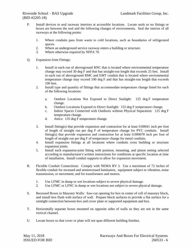
Riverside School – BAS Upgrade Landmark Facilities Group, Inc.
(BID #2205-18)
May 11, 2018 Raceways And Boxes For Electrical Systems
ISSUED FOR BID 260533 - 6
P. Install devices to seal raceway interiors at accessible locations. Locate seals so no fittings or
boxes are between the seal and the following changes of environments. Seal the interior of all
raceways at the following points:
1. Where conduits pass from warm to cold locations, such as boundaries of refrigerated
spaces.
2. Where an underground service raceway enters a building or structure.
3. Where otherwise required by NFPA 70.
Q. Expansion-Joint Fittings:
1. Install in each run of aboveground RNC that is located where environmental temperature
change may exceed 30 deg F and that has straight-run length that exceeds 25 feet. Install
in each run of aboveground RMC and EMT conduit that is located where environmental
temperature change may exceed 100 deg F and that has straight-run length that exceeds
100 feet.
2. Install type and quantity of fittings that accommodate temperature change listed for each
of the following locations:
a. Outdoor Locations Not Exposed to Direct Sunlight: 125 deg F temperature
change.
b. Outdoor Locations Exposed to Direct Sunlight: 155 deg F temperature change.
c. Indoor Spaces Connected with Outdoors without Physical Separation: 125 deg F
temperature change.
d. Attics: 135 deg F temperature change.
3. Install fitting(s) that provide expansion and contraction for at least 0.00041 inch per foot
of length of straight run per deg F of temperature change for PVC conduits. Install
fitting(s) that provide expansion and contraction for at least 0.000078 inch per foot of
length of straight run per deg F of temperature change for metal conduits.
4. Install expansion fittings at all locations where conduits cross building or structure
expansion joints.
5. Install each expansion-joint fitting with position, mounting, and piston setting selected
according to manufacturer's written instructions for conditions at specific location at time
of installation. Install conduit supports to allow for expansion movement.
R. Flexible Conduit Connections: Comply with NEMA RV 3. Use a maximum of 72 inches of
flexible conduit for recessed and semirecessed luminaires, equipment subject to vibration, noise
transmission, or movement; and for transformers and motors.
1. Use LFMC in damp or wet locations subject to severe physical damage.
2. Use LFMC or LFNC in damp or wet locations not subject to severe physical damage.
S. Recessed Boxes in Masonry Walls: Saw-cut opening for box in center of cell of masonry block,
and install box flush with surface of wall. Prepare block surfaces to provide a flat surface for a
raintight connection between box and cover plate or supported equipment and box.
T. Horizontally separate boxes mounted on opposite sides of walls so they are not in the same
vertical channel.
U. Locate boxes so that cover or plate will not span different building finishes.

Riverside School – BAS Upgrade Landmark Facilities Group, Inc.
(BID #2205-18)
May 11, 2018 Raceways And Boxes For Electrical Systems
ISSUED FOR BID 260533 - 7
V. Support boxes of three gangs or more from more than one side by spanning two framing
members or mounting on brackets specifically designed for the purpose.
W. Fasten junction and pull boxes to or support from building structure. Do not support boxes by
conduits.
X. Set metal floor boxes level and flush with finished floor surface.
3.3 PROTECTION
A. Protect coatings, finishes, and cabinets from damage and deterioration.
1. Repair damage to galvanized finishes with zinc-rich paint recommended by
manufacturer.
END OF SECTION 260533

Riverside School – BAS Upgrade Landmark Facilities Group, Inc.
(BID #2205-18)
May 11, 2018 Identification For Electrical Systems
ISSUED FOR BID 260553 - 1
SECTION 260553
IDENTIFICATION FOR ELECTRICAL SYSTEMS
PART 1 - GENERAL
1.1 RELATED DOCUMENTS
A. Drawings and general provisions of the Contract, including General and Supplementary
Conditions and Division 01 Specification Sections, apply to this Section.
1.2 SUMMARY
A. Section Includes:
1. Warning labels and signs.
2. Instruction signs.
3. Equipment identification labels.
4. Miscellaneous identification products.
1.3 QUALITY ASSURANCE
A. Comply with ANSI A13.1.
B. Comply with NFPA 70.
C. Comply with 29 CFR 1910.144 and 29 CFR 1910.145.
D. Comply with ANSI Z535.4 for safety signs and labels.
E. Adhesive-attached labeling materials, including label stocks, laminating adhesives, and inks
used by label printers, shall comply with UL 969.
1.4 COORDINATION
A. Coordinate identification names, abbreviations, colors, and other features with requirements in
other Sections requiring identification applications, Drawings, Shop Drawings, manufacturer's
wiring diagrams, and the Operation and Maintenance Manual; and with those required by codes,
standards, and 29 CFR 1910.145. Use consistent designations throughout Project.
B. Coordinate installation of identifying devices with completion of covering and painting of
surfaces where devices are to be applied.
C. Coordinate installation of identifying devices with location of access panels and doors.
D. Install identifying devices before installing acoustical ceilings and similar concealment.
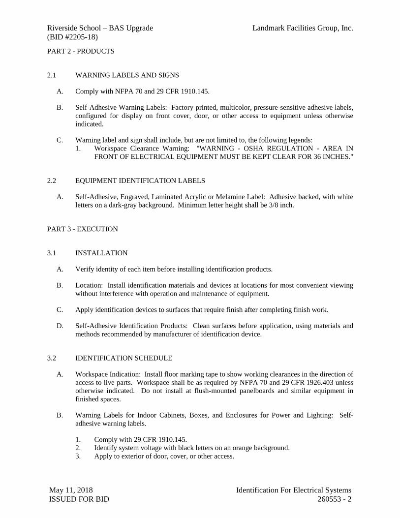
Riverside School – BAS Upgrade Landmark Facilities Group, Inc.
(BID #2205-18)
May 11, 2018 Identification For Electrical Systems
ISSUED FOR BID 260553 - 2
PART 2 - PRODUCTS
2.1 WARNING LABELS AND SIGNS
A. Comply with NFPA 70 and 29 CFR 1910.145.
B. Self-Adhesive Warning Labels: Factory-printed, multicolor, pressure-sensitive adhesive labels,
configured for display on front cover, door, or other access to equipment unless otherwise
indicated.
C. Warning label and sign shall include, but are not limited to, the following legends:
1. Workspace Clearance Warning: "WARNING - OSHA REGULATION - AREA IN
FRONT OF ELECTRICAL EQUIPMENT MUST BE KEPT CLEAR FOR 36 INCHES."
2.2 EQUIPMENT IDENTIFICATION LABELS
A. Self-Adhesive, Engraved, Laminated Acrylic or Melamine Label: Adhesive backed, with white
letters on a dark-gray background. Minimum letter height shall be 3/8 inch.
PART 3 - EXECUTION
3.1 INSTALLATION
A. Verify identity of each item before installing identification products.
B. Location: Install identification materials and devices at locations for most convenient viewing
without interference with operation and maintenance of equipment.
C. Apply identification devices to surfaces that require finish after completing finish work.
D. Self-Adhesive Identification Products: Clean surfaces before application, using materials and
methods recommended by manufacturer of identification device.
3.2 IDENTIFICATION SCHEDULE
A. Workspace Indication: Install floor marking tape to show working clearances in the direction of
access to live parts. Workspace shall be as required by NFPA 70 and 29 CFR 1926.403 unless
otherwise indicated. Do not install at flush-mounted panelboards and similar equipment in
finished spaces.
B. Warning Labels for Indoor Cabinets, Boxes, and Enclosures for Power and Lighting: Self-
adhesive warning labels.
1. Comply with 29 CFR 1910.145.
2. Identify system voltage with black letters on an orange background.
3. Apply to exterior of door, cover, or other access.

Riverside School – BAS Upgrade Landmark Facilities Group, Inc.
(BID #2205-18)
May 11, 2018 Identification For Electrical Systems
ISSUED FOR BID 260553 - 3
C. Equipment Identification Labels: On each unit of equipment, install unique designation label
that is consistent with wiring diagrams, schedules, and the Operation and Maintenance Manual.
Apply labels to disconnect switches and protection equipment, central or master units, control
panels, control stations, terminal cabinets, and racks of each system. Systems include power,
lighting, control, communication, signal, monitoring, and alarm systems unless equipment is
provided with its own identification.
1. Labeling Instructions:
a. Indoor Equipment: Adhesive film label. Unless otherwise indicated, provide a
single line of text with 1/2-inch-high letters on 1-1/2-inch-high label; where two
lines of text are required, use labels 2 inches high.
b. Outdoor Equipment: Engraved, laminated acrylic or melamine label.
c. Elevated Components: Increase sizes of labels and letters to those appropriate for
viewing from the floor.
d. Unless provided with self-adhesive means of attachment, fasten labels with
appropriate mechanical fasteners that do not change the NEMA or NRTL rating of
the enclosure.
2. Equipment to Be Labeled:
a. Enclosures and electrical cabinets.
b. Access doors and panels for concealed electrical items.
c. Enclosed switches.
d. Enclosed circuit breakers.
e. Enclosed controllers.
f. Push-button stations.
END OF SECTION 260553

RIVERSIDE ELEMENTARY SCHOOLBUILDING AUTOMATION SYSTEM (BAS)
UPGRADE
FACILITIESGROUP, INC.
LANDMARK
(203) 866-8019 Fax(203) 866-4626 TelNorwalk, CT 06855252 East Avenue
DOCUMENTS PREPARED BY:
ISSUE: DATE:FOR BID MAY 11, 2018BID # 2205-18
M-001
PROJECT COVER SHEET
5/11/18
NONE RS
\DIR\DWG
BUILDING AUTOMATION SYSTEM
90 HENDRIE AVE., RIVERSIDE CT 06876RIVERSIDE SCHOOL
GR
RS
FACILITIESGROUP, INC.
LANDMARK
(203) 866-8019 Fax(203) 866-4626 TelNorwalk, CT 06855252 East Avenue
KEY PLAN
(BAS) UPGRADE
\DIR\DWG
BUILDING AUTOMATION SYSTEM
90 HENDRIE AVE., RIVERSIDE CT 06876RIVERSIDE SCHOOL
GR
RS
FACILITIESGROUP, INC.
LANDMARK
(203) 866-8019 Fax(203) 866-4626 TelNorwalk, CT 06855252 East Avenue
KEY PLAN
(BAS) UPGRADE
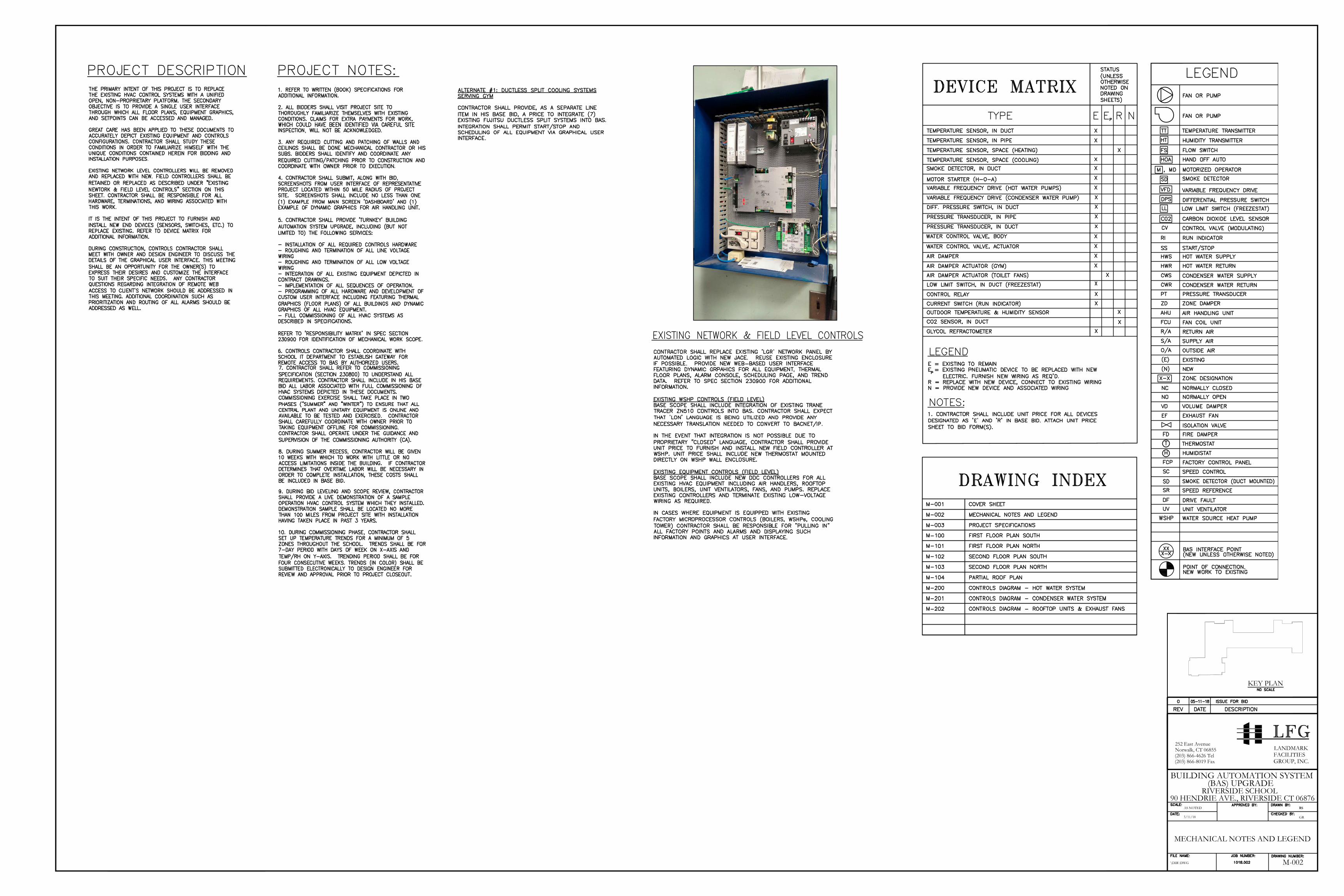
M-002
MECHANICAL NOTES AND LEGEND
5/11/18
AS NOTED RS
\DIR\DWG
BUILDING AUTOMATION SYSTEM
90 HENDRIE AVE., RIVERSIDE CT 06876RIVERSIDE SCHOOL
GR
RS
FACILITIESGROUP, INC.
LANDMARK
(203) 866-8019 Fax(203) 866-4626 TelNorwalk, CT 06855252 East Avenue
KEY PLAN
(BAS) UPGRADE

PROJECT SPECIFICATIONS
M-003
MECHANICAL SPECIFICATIONS
5/11/18
AS NOTED
RS
RS
\DIR\DWG
BUILDING AUTOMATION SYSTEM
90 HENDRIE AVE., RIVERSIDE CT 06876RIVERSIDE SCHOOL
GR
RS
FACILITIESGROUP, INC.
LANDMARK
(203) 866-8019 Fax(203) 866-4626 TelNorwalk, CT 06855252 East Avenue
KEY PLAN
(BAS) UPGRADE
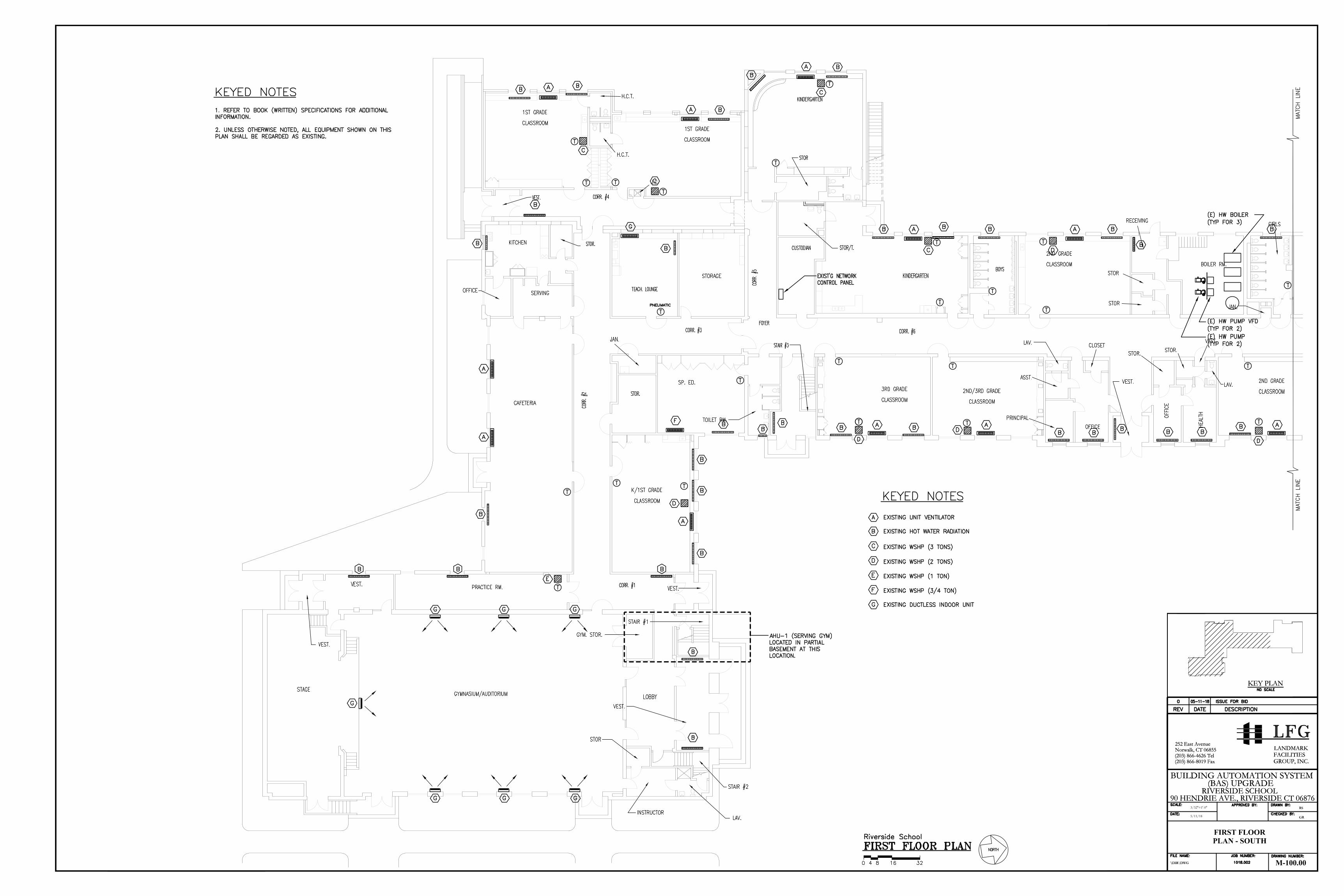
C
H
C
H
C
H
C
H
C
H
C
H
C
H
C
H
C
H
C
H
C
H
C
H
C
H
C
H
C
H
C
H
C
H
C
H
\DIR\DWG
BUILDING AUTOMATION SYSTEM
90 HENDRIE AVE., RIVERSIDE CT 06876RIVERSIDE SCHOOL
GR
RS
FACILITIESGROUP, INC.
LANDMARK
(203) 866-8019 Fax(203) 866-4626 TelNorwalk, CT 06855252 East Avenue
KEY PLAN
(BAS) UPGRADE
FIRST FLOORPLAN - SOUTH
\DIR\DWG
BUILDING AUTOMATION SYSTEM
90 HENDRIE AVE., RIVERSIDE CT 06876RIVERSIDE SCHOOL
GR
RS
FACILITIESGROUP, INC.
LANDMARK
(203) 866-8019 Fax(203) 866-4626 TelNorwalk, CT 06855252 East Avenue
KEY PLAN
(BAS) UPGRADE
M-100.00
3/32''=1'-0''
5/11/18
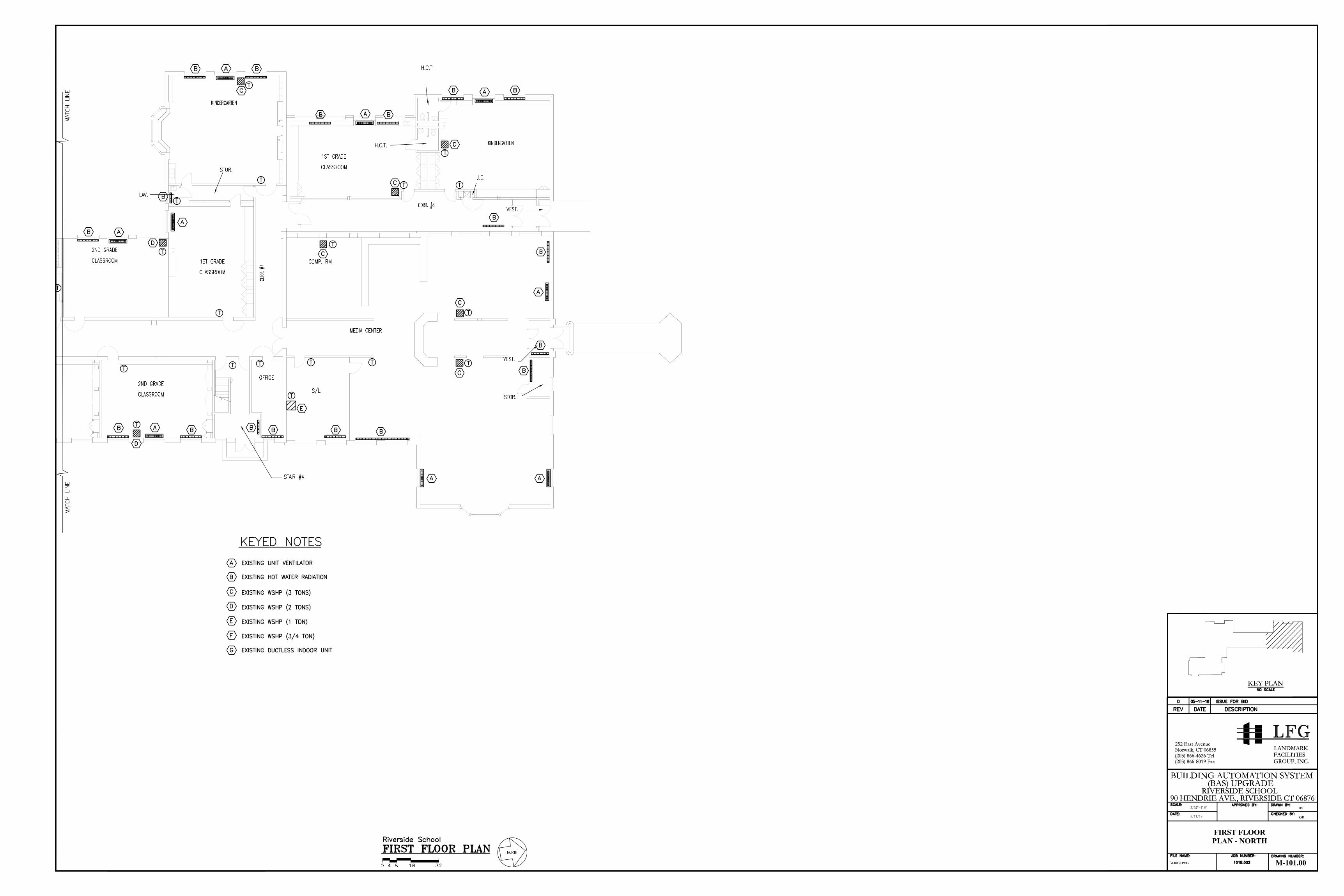
C
H
C
H
C
H
C
H
C
H
C
H
C
H
\DIR\DWG
BUILDING AUTOMATION SYSTEM
90 HENDRIE AVE., RIVERSIDE CT 06876RIVERSIDE SCHOOL
GR
RS
FACILITIESGROUP, INC.
LANDMARK
(203) 866-8019 Fax(203) 866-4626 TelNorwalk, CT 06855252 East Avenue
KEY PLAN
(BAS) UPGRADE
FIRST FLOORPLAN - NORTH
\DIR\DWG
BUILDING AUTOMATION SYSTEM
90 HENDRIE AVE., RIVERSIDE CT 06876RIVERSIDE SCHOOL
GR
RS
FACILITIESGROUP, INC.
LANDMARK
(203) 866-8019 Fax(203) 866-4626 TelNorwalk, CT 06855252 East Avenue
KEY PLAN
(BAS) UPGRADE
M-101.00
3/32''=1'-0''
5/11/18

C
H
C
H
C
H
C
H
C
H
C
H
C
H
C
H
C
H
\DIR\DWG
BUILDING AUTOMATION SYSTEM
90 HENDRIE AVE., RIVERSIDE CT 06876RIVERSIDE SCHOOL
GR
RS
FACILITIESGROUP, INC.
LANDMARK
(203) 866-8019 Fax(203) 866-4626 TelNorwalk, CT 06855252 East Avenue
KEY PLAN
(BAS) UPGRADE
SECOND FLOORPLAN - SOUTH
\DIR\DWG
BUILDING AUTOMATION SYSTEM
90 HENDRIE AVE., RIVERSIDE CT 06876RIVERSIDE SCHOOL
GR
RS
FACILITIESGROUP, INC.
LANDMARK
(203) 866-8019 Fax(203) 866-4626 TelNorwalk, CT 06855252 East Avenue
KEY PLAN
(BAS) UPGRADE
M-102.00
3/32''=1'-0''
5/11/18

\DIR\DWG
BUILDING AUTOMATION SYSTEM
90 HENDRIE AVE., RIVERSIDE CT 06876RIVERSIDE SCHOOL
GR
RS
FACILITIESGROUP, INC.
LANDMARK
(203) 866-8019 Fax(203) 866-4626 TelNorwalk, CT 06855252 East Avenue
KEY PLAN
(BAS) UPGRADE
SECOND FLOORPLAN - NORTH
\DIR\DWG
BUILDING AUTOMATION SYSTEM
90 HENDRIE AVE., RIVERSIDE CT 06876RIVERSIDE SCHOOL
GR
RS
FACILITIESGROUP, INC.
LANDMARK
(203) 866-8019 Fax(203) 866-4626 TelNorwalk, CT 06855252 East Avenue
KEY PLAN
(BAS) UPGRADE
M-103.00
3/32''=1'-0''
5/11/18

\DIR\DWG
BUILDING AUTOMATION SYSTEM
90 HENDRIE AVE., RIVERSIDE CT 06876RIVERSIDE SCHOOL
GR
RS
FACILITIESGROUP, INC.
LANDMARK
(203) 866-8019 Fax(203) 866-4626 TelNorwalk, CT 06855252 East Avenue
KEY PLAN
(BAS) UPGRADE
PARTIAL ROOFPLAN
\DIR\DWG
BUILDING AUTOMATION SYSTEM
90 HENDRIE AVE., RIVERSIDE CT 06876RIVERSIDE SCHOOL
GR
RS
FACILITIESGROUP, INC.
LANDMARK
(203) 866-8019 Fax(203) 866-4626 TelNorwalk, CT 06855252 East Avenue
KEY PLAN
(BAS) UPGRADE
M-104.00
3/32''=1'-0''
5/11/18

M-200
CONTROLS DIAGRAMHOT WATER SYSTEM
.
5/11/18
AS NOTED RS
\DIR\DWG
BUILDING AUTOMATION SYSTEM
90 HENDRIE AVE., RIVERSIDE CT 06876RIVERSIDE SCHOOL
GR
RS
FACILITIESGROUP, INC.
LANDMARK
(203) 866-8019 Fax(203) 866-4626 TelNorwalk, CT 06855252 East Avenue
KEY PLAN
(BAS) UPGRADE

M-201
CONTROLS DIAGRAM -CONDENSER WATER SYSTEM
.
5/11/18
AS NOTED RS
\DIR\DWG
BUILDING AUTOMATION SYSTEM
90 HENDRIE AVE., RIVERSIDE CT 06876RIVERSIDE SCHOOL
GR
RS
FACILITIESGROUP, INC.
LANDMARK
(203) 866-8019 Fax(203) 866-4626 TelNorwalk, CT 06855252 East Avenue
KEY PLAN
(BAS) UPGRADE
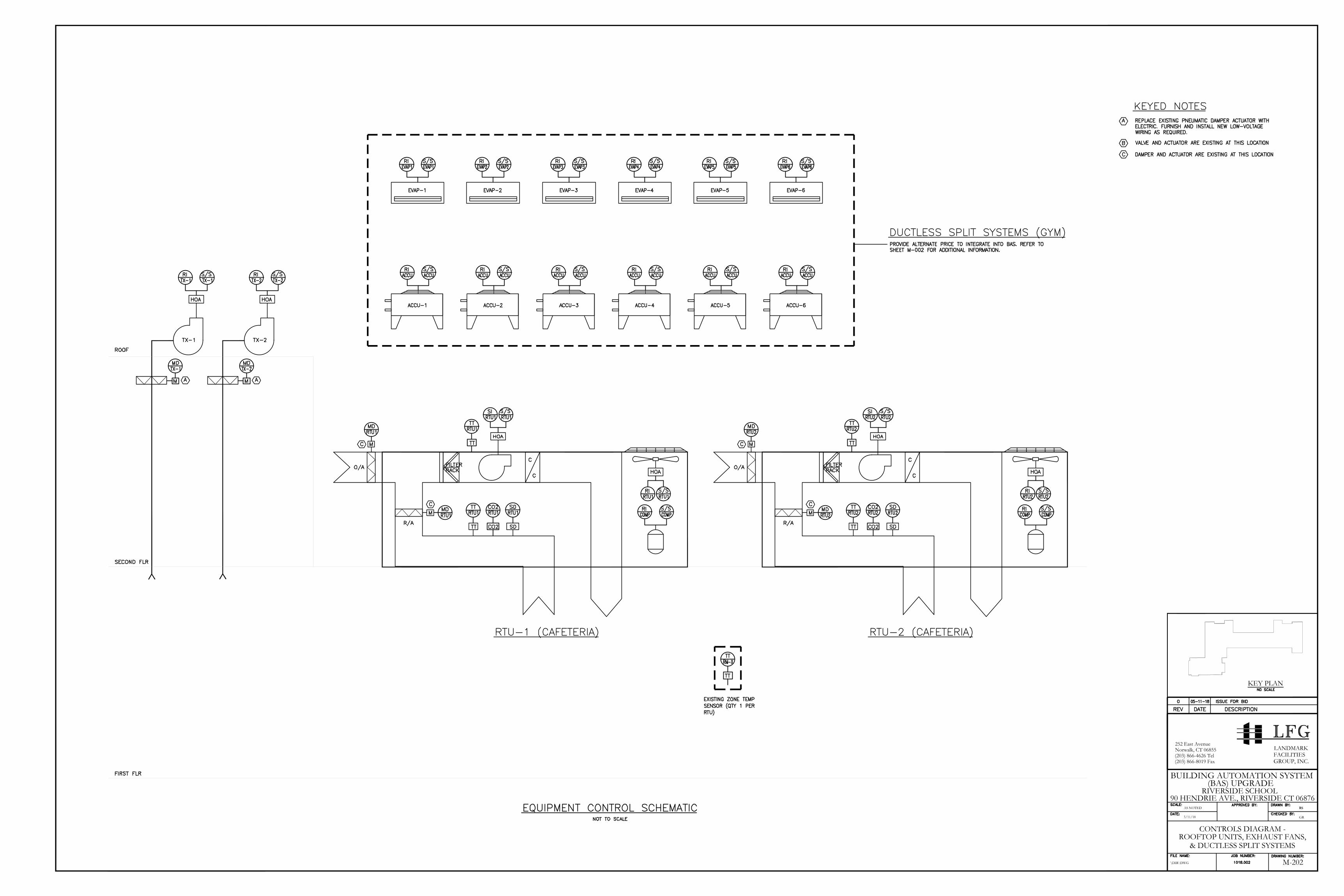
M-202
CONTROLS DIAGRAM -ROOFTOP UNITS, EXHAUST FANS,
.
5/11/18
AS NOTED RS
\DIR\DWG
BUILDING AUTOMATION SYSTEM
90 HENDRIE AVE., RIVERSIDE CT 06876RIVERSIDE SCHOOL
GR
RS
FACILITIESGROUP, INC.
LANDMARK
(203) 866-8019 Fax(203) 866-4626 TelNorwalk, CT 06855252 East Avenue
KEY PLAN
(BAS) UPGRADE
& DUCTLESS SPLIT SYSTEMS