Embed Size (px)
Citation preview
Project: 4x225MW Arun-3 (HEP), Nepal Bharat Heavy Electricals Limited Customer: SJVN Arun -III Power Development Document No. TB 405 510 010 Company (P) Ltd (SAPDC) Consultant: SJVN Limited Technical Specification: 400 kV Wave Trap
Section-1 Page 1 of 5
SECTION 1
SCOPE, SPECIFIC TECHNICAL REQUIREMENTS AND QUANTITIES
1.0 SCOPE
This technical specification covers the requirements of design, manufacture, testing at works, packing and dispatch of 400kV Wave Traps complete with accessories as listed under this specification.
This section covers the specific technical requirements of Wave Trap. This constitutes minimum technical parameters for the above item as specified by the customer/consultant (SAPDC / SJVN). The offered equipment shall also comply with the General Technical Requirements for the project as detailed under section-3 of this specification. The specification comprises of following sections: Section-1: Scope, Specific Technical Requirements & Bill of Quantities Section-2: Equipment Specification Section-3: Project Details & General Technical Requirements Section-4: Guaranteed Technical Particulars Section-5: Checklist In case of any conflict between various sections, order of precedence shall be in the
same order as listed above.
1.1 THE EQUIPMENT IS REQUIRED FOR THE FOLLOWING PROJECT
Name of customer: SJVN Arun-III Power Development Company (P) Ltd (SAPDC) Name of consultant: SJVN Limited Name of Project: 4x225MW, Arun-3 HEP, Nepal Refer Section - 3 for Project Details and General Specifications. 1.2 TECHNICAL PRE-QUALIFYING REQUIREMENTS
For Technical Pre-qualifying requirement, refer Annexure-TQR.
Project: 4x225MW Arun-3 (HEP), Nepal Bharat Heavy Electricals Limited Customer: SJVN Arun -III Power Development Document No. TB 405 510 010 Company (P) Ltd (SAPDC) Consultant: SJVN Limited Technical Specification: 400 kV Wave Trap
Section-1 Page 2 of 5
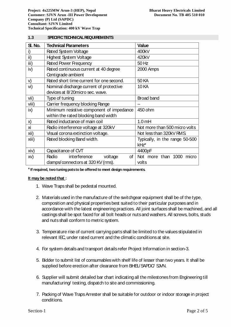
1.3 SPECIFIC TECHNICAL REQUIREMENTS
Sl. No. Technical Parameters Value i) Rated System Voltage 400kV ii) Highest System Voltage 420kV iii) Rated Power Frequency 50 Hz iv) Rated continuous current at 40 degree
Centigrade ambient 2000 Amps
v) Rated short time current for one second. 50 KA vi) Nominal discharge current of protective
devices at 8/20micro sec. wave. 10 KA
vii) Type of tuning Broad band viii) Carrier frequency blocking Range -- ix) Minimum resistive component of impedance
within the rated blocking band width 450 ohm
x) Rated inductance of main coil 1.0 mH xi Radio interference voltage at 320kV Not more than 500 micro volts xii) Visual corona extinction voltage. Not less than 320kV RMS. xiii) Rated blocking Band width. Typically, in the range 50-500
kHz* xiv) Capacitance of CVT 4400pF xv) Radio interference voltage of
clamps/connectors at 320 KV (rms). Not more than 1000 micro volts
*If required, two tuning pots to be offered to meet design requirements.
It may be noted that :
1. Wave Traps shall be pedestal mounted.
2. Materials used in the manufacture of the switchgear equipment shall be of the type, composition and physical properties best suited to their particular purposes and in accordance with the latest engineering practices. All joint surfaces shall be machined, and all castings shall be spot faced for all bolt heads or nuts and washers. All screws, bolts, studs and nuts shall conform to metric system.
3. Temperature rise of current carrying parts shall be limited to the values stipulated in
relevant IEC, under rated current and the climatic conditions at site.
4. For system details and transport details refer Project Information in section-3.
5. Bidder to submit list of consumables with shelf life of lesser than two years. It shall be supplied before erection after clearance from BHEL/SAPDC/ SJVN.
6. Supplier will submit detailed bar chart indicating all the milestones from Engineering till
manufacturing/ testing, dispatch to site and commissioning. 7. Packing of Wave Traps Arrester shall be suitable for outdoor or indoor storage in project
conditions.
Project: 4x225MW Arun-3 (HEP), Nepal Bharat Heavy Electricals Limited Customer: SJVN Arun -III Power Development Document No. TB 405 510 010 Company (P) Ltd (SAPDC) Consultant: SJVN Limited Technical Specification: 400 kV Wave Trap
Section-1 Page 3 of 5
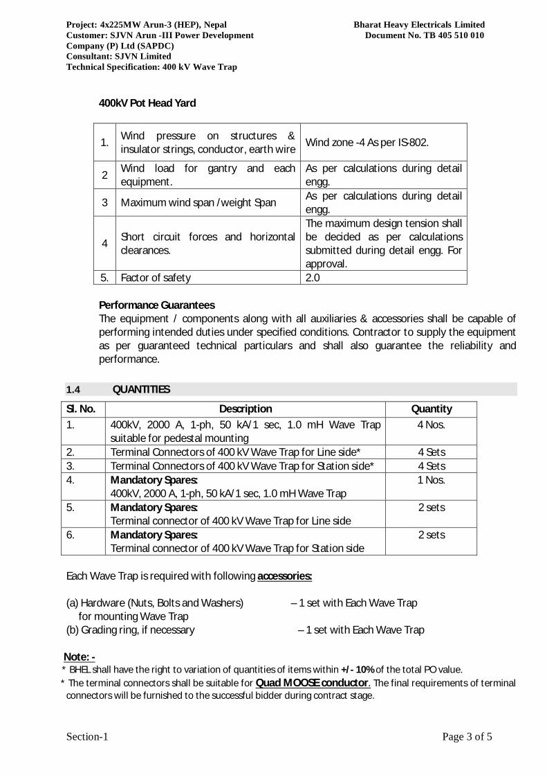
400kV Pot Head Yard
1. Wind pressure on structures & insulator strings, conductor, earth wire Wind zone -4 As per IS-802.
2 Wind load for gantry and each equipment.
As per calculations during detail engg.
3 Maximum wind span /weight Span As per calculations during detail engg.
4 Short circuit forces and horizontal clearances.
The maximum design tension shall be decided as per calculations submitted during detail engg. For approval.
5. Factor of safety 2.0 Performance Guarantees The equipment / components along with all auxiliaries & accessories shall be capable of performing intended duties under specified conditions. Contractor to supply the equipment as per guaranteed technical particulars and shall also guarantee the reliability and performance.
1.4 QUANTITIES
Sl. No. Description Quantity 1.
400kV, 2000 A, 1-ph, 50 kA/1 sec, 1.0 mH Wave Trap suitable for pedestal mounting
4 Nos.
2. Terminal Connectors of 400 kV Wave Trap for Line side* 4 Sets 3. Terminal Connectors of 400 kV Wave Trap for Station side* 4 Sets 4. Mandatory Spares:
400kV, 2000 A, 1-ph, 50 kA/1 sec, 1.0 mH Wave Trap 1 Nos.
5. Mandatory Spares:
Terminal connector of 400 kV Wave Trap for Line side 2 sets
6. Mandatory Spares:
Terminal connector of 400 kV Wave Trap for Station side 2 sets
Each Wave Trap is required with following accessories: (a) Hardware (Nuts, Bolts and Washers) – 1 set with Each Wave Trap for mounting Wave Trap
(b) Grading ring, if necessary – 1 set with Each Wave Trap Note: -
* BHEL shall have the right to variation of quantities of items within +/- 10% of the total PO value. * The terminal connectors shall be suitable for Quad MOOSE conductor. The final requirements of terminal
connectors will be furnished to the successful bidder during contract stage.
Project: 4x225MW Arun-3 (HEP), Nepal Bharat Heavy Electricals Limited Customer: SJVN Arun -III Power Development Document No. TB 405 510 010 Company (P) Ltd (SAPDC) Consultant: SJVN Limited Technical Specification: 400 kV Wave Trap
Section-1 Page 4 of 5
1.5 TYPE TESTS
The bidder shall submit the certificates from Govt. approved labs/ accredited laboratories of the type tests listed in Section 2 which should have been carried out within last five (5) years from the date of bid opening (09.02.2018). These type test reports should be for the tests conducted on the equipment similar to those proposed to be supplied under this contract and the test(s) should have been either conducted at an independent laboratory or should have been witnessed by a client. In case the bidder is not able to submit report of the type test(s) conducted within last five years from the date of bid opening, or in case the type test report(s) are not found to be meeting the specification requirements, the contractor shall conduct the type tests without any cost and delivery implication to BHEL/SAPDC/SJVN.
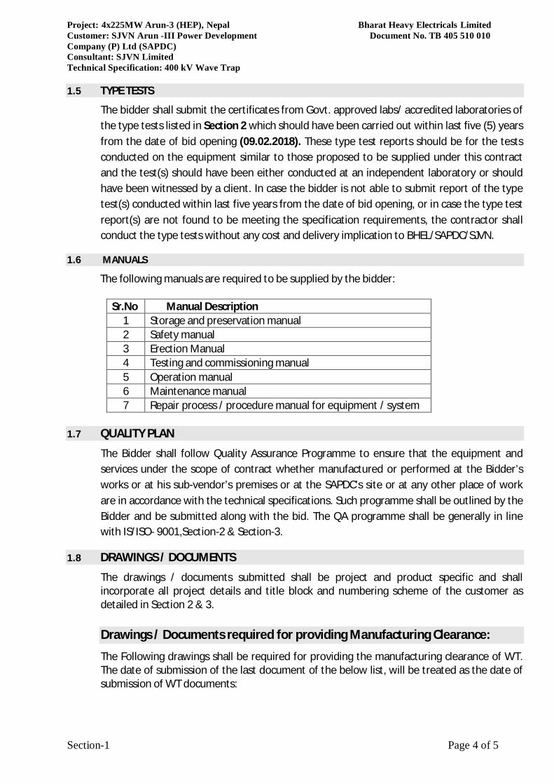
1.6 MANUALS
The following manuals are required to be supplied by the bidder:
Sr.No Manual Description 1 Storage and preservation manual 2 Safety manual 3 Erection Manual 4 Testing and commissioning manual 5 Operation manual 6 Maintenance manual 7 Repair process / procedure manual for equipment / system
1.7 QUALITY PLAN
The Bidder shall follow Quality Assurance Programme to ensure that the equipment and services under the scope of contract whether manufactured or performed at the Bidder’s works or at his sub-vendor’s premises or at the SAPDC’s site or at any other place of work are in accordance with the technical specifications. Such programme shall be outlined by the Bidder and be submitted along with the bid. The QA programme shall be generally in line with IS/ISO- 9001,Section-2 & Section-3.
1.8 DRAWINGS / DOCUMENTS
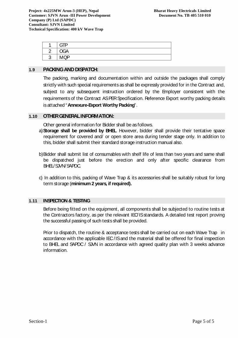
The drawings / documents submitted shall be project and product specific and shall incorporate all project details and title block and numbering scheme of the customer as detailed in Section 2 & 3. Drawings / Documents required for providing Manufacturing Clearance:
The Following drawings shall be required for providing the manufacturing clearance of WT. The date of submission of the last document of the below list, will be treated as the date of submission of WT documents:
Project: 4x225MW Arun-3 (HEP), Nepal Bharat Heavy Electricals Limited Customer: SJVN Arun -III Power Development Document No. TB 405 510 010 Company (P) Ltd (SAPDC) Consultant: SJVN Limited Technical Specification: 400 kV Wave Trap
Section-1 Page 5 of 5
1 GTP 2 OGA 3 MQP
1.9 PACKING AND DISPATCH:
The packing, marking and documentation within and outside the packages shall comply strictly with such special requirements as shall be expressly provided for in the Contract and, subject to any subsequent instruction ordered by the Employer consistent with the requirements of the Contract AS PER Specification. Reference Export worthy packing details is attached “Annexure-Export Worthy Packing”.
1.10 OTHER GENERAL INFORMATION:
Other general information for Bidder shall be as follows. a) Storage shall be provided by BHEL. However, bidder shall provide their tentative space
requirement for covered and/ or open store area during tender stage only. In addition to this, bidder shall submit their standard storage instruction manual also.
b) Bidder shall submit list of consumables with shelf life of less than two years and same shall be dispatched just before the erection and only after specific clearance from BHEL/SJVN/SAPDC.
c) In addition to this, packing of Wave Trap & its accessories shall be suitably robust for long
term storage (minimum 2 years, if required).
1.11 INSPECTION & TESTING
Before being fitted on the equipment, all components shall be subjected to routine tests at the Contractors factory, as per the relevant IEC/IS standards. A detailed test report proving the successful passing of such tests shall be provided. Prior to dispatch, the routine & acceptance tests shall be carried out on each Wave Trap in accordance with the applicable IEC /IS and the material shall be offered for final inspection to BHEL and SAPDC / SJVN in accordance with agreed quality plan with 3 weeks advance information.
Project: 4x225MW Arun-3 (HEP), Nepal Bharat Heavy Electricals Limited Customer: SJVN Arun -III Power Development Document No. TB 405 510 010 Company (P) Ltd (SAPDC) Consultant: SJVN Limited Technical Specification: 400 kV Wave Trap
Section-2 Page 1 of 6
SECTION-2
EQUIPMENT SPECIFICATION
2.0 SCOPE This technical specification covers the requirements of design, manufacture, testing at works, packing and despatch of Line Traps. No deviation from the requirements specified in various clauses of this specification shall be allowed.
2.1 APPLICABLE STANDARDS The Line Traps shall comply with applicable parts of the following standards, except as otherwise specified herein: IEC: 60099(Part –1 and 4) Surge arrester IEC: 60353 Line Trap. IS 8792 Line Traps. IS 8793 Method of Tests for Line Trap. IEC: 60 High Voltage Test Techniques.
IS 3070 (Part I) Specification for Surge Arresters for AC System. IS 5561 Specification of electric power Connectors.
The equipment shall also meet with following International publication on the subject: CIGRE 319- 1962 CIGRE 35-01-1974 IEEE (USA) Vol.83 No.7 PAS The equipment shall conform to the latest applicable standards and their amendments. 2.2 FEATURES 2.2.1 General Description The wave traps offered shall be complete with tuning devices. These shall be suitable for 420KV three phase neutral solidly grounded systems and prevent undue loss of carrier signal for all power system conditions. The wave trap should offer negligible impedance to any frequency of 50 Hz and high impedance to any frequency band appropriate to the carrier communication. 2.2.2 Construction The wave traps shall be designed and manufactured to withstand, without damage under service conditions, the effects of external short circuits. The wave traps should be robust in construction and shall be capable of withstanding the electromagnetic forces and thermal effects of the rated short time current for a duration of one second after previous operation at rated continuous current at the specified maximum air temperature.
Project: 4x225MW Arun-3 (HEP), Nepal Bharat Heavy Electricals Limited Customer: SJVN Arun -III Power Development Document No. TB 405 510 010 Company (P) Ltd (SAPDC) Consultant: SJVN Limited Technical Specification: 400 kV Wave Trap
Section-2 Page 2 of 6
2.2.3 Frequencies for PLCC Power line carrier communication, the frequencies for Dhalkebar feeders shall be finalized during detailed engineering. 2.2.4 General Technical requirements a) Wave traps consisting of a main coil in the form of inductor, a tuning device and a protective
device shall be inserted into transmission line to prevent undue loss of carrier signal for all power system conditions. Its impedance shall be negligible at power frequency (50 Hz) so as not to disturb power transmission but shall be relatively high over the frequency band appropriate to carrier transmission.
b) The surge arrester shall be station class current limiting active gap / gap-less type. Its rated discharge current shall be 10 / 20 kA. Co-ordination, however, shall be done by taking 20kA at 8/20 micro sec discharge current into account. Bidder has to furnish full justification in case the gap-less metal oxide arrester is recommended at contract stage. The SA provided with line trap of each rating shall fully comply with the requirements of IS 3070 Part-I/ IEC-60099-1Part-1/IEC-60099-4. The SA provided with the line trap shall be subjected to routine and acceptance tests as per IEC-60099-1 (Part-1) /IEC-60099-4.
c) Wave trap shall consist of a main coil designed to carry continuously the rated current without
exceeding the limit of temperature rise. It shall be supplemented with a protective device and tuning device. Also, suitable corona rings shall be provided to meet corona and radio interference performance.
d) Wave trap shall be broad band tuned for its entire carrier frequency range. Resistive component
of impedance of the wave trap within its carrier frequency blocking range shall not be less than 450 ohms.
e) Wave trap shall be provided with a protective device in the form of surge arresters which shall be
designed and arranged such that neither significant alteration in its protective function nor physical damage shall result from either temperature rise or the magnetic field of the main coil at continuous rated current or rated short time current. The protective device shall neither enter into operation nor remain in operation, transient actuation by the power frequency voltage developed across the wave trap by the rated short time current. The protective device shall be shunt connected to the main coil turning device.
f) The surge arrester shall be station class metal oxide type. Its rated discharge current shall be 10
KA. g) The surge arrester provided with the wave trap shall fully comply with the requirements of IS-
3070. It shall conform to type tests as applicable and type test certificate for the same shall be submitted by the Bidder.
h) The surge arrester provided with the wave trap shall be subject to routine and acceptance tests as
per IS-3070.
Project: 4x225MW Arun-3 (HEP), Nepal Bharat Heavy Electricals Limited Customer: SJVN Arun -III Power Development Document No. TB 405 510 010 Company (P) Ltd (SAPDC) Consultant: SJVN Limited Technical Specification: 400 kV Wave Trap
Section-2 Page 3 of 6
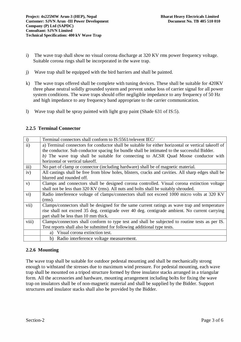
i) The wave trap shall show no visual corona discharge at 320 KV rms power frequency voltage.
Suitable corona rings shall be incorporated in the wave trap. j) Wave trap shall be equipped with the bird barriers and shall be painted. k) The wave traps offered shall be complete with tuning devices. These shall be suitable for 420KV
three phase neutral solidly grounded system and prevent undue loss of carrier signal for all power system conditions. The wave traps should offer negligible impedance to any frequency of 50 Hz and high impedance to any frequency band appropriate to the carrier communication.
l) Wave trap shall be spray painted with light gray paint (Shade 631 of IS:5).
2.2.5 Terminal Connector i) Terminal connectors shall conform to IS:5561/relevent IEC/ ii)
a) Terminal connectors for conductor shall be suitable for either horizontal or vertical takeoff of the conductor. Sub conductor spacing for bundle shall be intimated to the successful Bidder. b) The wave trap shall be suitable for connecting to ACSR Quad Moose conductor with horizontal or vertical takeoff.
iii) No part of clamp or connector (including hardware) shall be of magnetic material. iv) All castings shall be free from blow holes, blisters, cracks and cavities. All sharp edges shall be
blurred and rounded off. v) Clamps and connectors shall be designed corona controlled. Visual corona extinction voltage
shall not be less than 320 KV (rms). All nuts and bolts shall be suitably shrouded. vi) Radio interference voltage of clamps/connectors shall not exceed 1000 micro volts at 320 KV
(rms). vii)
Clamps/connectors shall be designed for the same current ratings as wave trap and temperature rise shall not exceed 35 deg. centigrade over 40 deg. centigrade ambient. No current carrying part shall be less than 10 mm thick.
viii) Clamps/connectors shall conform to type test and shall be subjected to routine tests as per IS. Test reports shall also be submitted for following additional type tests.
a) Visual corona extinction test. b) Radio interference voltage measurement. 2.2.6 Mounting The wave trap shall be suitable for outdoor pedestal mounting and shall be mechanically strong enough to withstand the stresses due to maximum wind pressure. For pedestal mounting, each wave trap shall be mounted on a tripod structure formed by three insulator stacks arranged in a triangular form. All the accessories and hardware, mounting arrangement including bolts for fixing the wave trap on insulators shall be of non-magnetic material and shall be supplied by the Bidder. Support structures and insulator stacks shall also be provided by the Bidder.
Project: 4x225MW Arun-3 (HEP), Nepal Bharat Heavy Electricals Limited Customer: SJVN Arun -III Power Development Document No. TB 405 510 010 Company (P) Ltd (SAPDC) Consultant: SJVN Limited Technical Specification: 400 kV Wave Trap
Section-2 Page 4 of 6
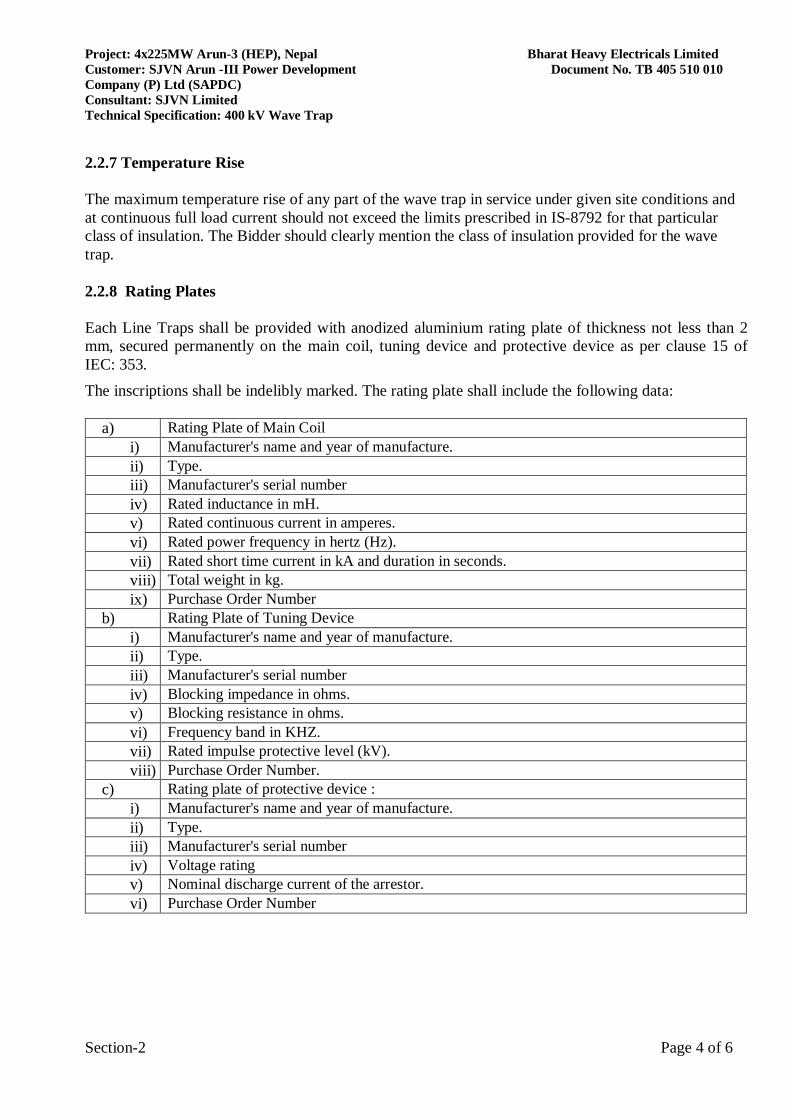
2.2.7 Temperature Rise The maximum temperature rise of any part of the wave trap in service under given site conditions and at continuous full load current should not exceed the limits prescribed in IS-8792 for that particular class of insulation. The Bidder should clearly mention the class of insulation provided for the wave trap. 2.2.8 Rating Plates Each Line Traps shall be provided with anodized aluminium rating plate of thickness not less than 2 mm, secured permanently on the main coil, tuning device and protective device as per clause 15 of IEC: 353. The inscriptions shall be indelibly marked. The rating plate shall include the following data:
a) Rating Plate of Main Coil i) Manufacturer's name and year of manufacture. ii) Type. iii) Manufacturer's serial number iv) Rated inductance in mH. v) Rated continuous current in amperes. vi) Rated power frequency in hertz (Hz). vii) Rated short time current in kA and duration in seconds. viii) Total weight in kg. ix) Purchase Order Number
b) Rating Plate of Tuning Device i) Manufacturer's name and year of manufacture. ii) Type. iii) Manufacturer's serial number iv) Blocking impedance in ohms. v) Blocking resistance in ohms. vi) Frequency band in KHZ. vii) Rated impulse protective level (kV). viii) Purchase Order Number.
c) Rating plate of protective device : i) Manufacturer's name and year of manufacture. ii) Type. iii) Manufacturer's serial number iv) Voltage rating v) Nominal discharge current of the arrestor. vi) Purchase Order Number
Project: 4x225MW Arun-3 (HEP), Nepal Bharat Heavy Electricals Limited Customer: SJVN Arun -III Power Development Document No. TB 405 510 010 Company (P) Ltd (SAPDC) Consultant: SJVN Limited Technical Specification: 400 kV Wave Trap
Section-2 Page 5 of 6
2.2.9 WELDING All the welding included in the manufacture of line traps shall be performed by personnel and procedure qualified in accordance with ASME-IX and all the critical welds shall be subjected to NDT as applicable. 2.3 TESTS
The Line Traps, Connectors & Surge Arresters shall be accompanied by Type, routine and acceptance testing as per latest IS/ IEC standards. The Bidder shall only submit the certificates from Govt. approved labs/ accredited laboratories of the type tests listed under Category -II for the respective equipment which should have been carried out within last five (5) years from the date of bid opening 09.02.2018. These reports should be for the tests conducted on the equipment similar to those proposed to be supplied under this contract and the test(s) should have been either conducted at an independent laboratory or should have been witnessed by a client. In case the contractor is not able to submit report of the type test(s) conducted within last five years from the date of bid opening, or in case the type test report(s) are not found to be meeting the specification requirements, the contractor shall conduct the test without any financial implication to purchaser. Following routine tests shall be carried out on the Wave traps a) Measurement of the rated inductance of the main coil b) Measurement of power frequency inductance of the main coil c) Measurement of blocking resistance and blocking impedance d) Measurement of tapping loss and tapping loss based on the blocking resistance Connectors shall conform to the type test asper IS-5561. Type test certificate for the following tests shall be submitted by the bidder. The type test certificate from the manufacturer shall only be acceptable. 1) Tensile tests 2) Resistance test 3) Temperature-rise test 4) Short time current test 5) Dimensional check. 6) Galvanizing test, where applicable. Wave trap shall conform to the type test as per IEC-353. Type test certificate for the following tests shall be submitted by the bidder. The type test certificate from the manufacturer shall only be acceptable All valid type test reports as per latest IS/ IEC for Line Traps shall be submitted for approval at contract stage, which shall include the following. 1 Measurement of rated inductance of main coil. 2 Measurement of temperature rise. 3 Impulse voltage test. 4 Short time current test. 5 Measurement of blocking resistance and blocking impedance.
Project: 4x225MW Arun-3 (HEP), Nepal Bharat Heavy Electricals Limited Customer: SJVN Arun -III Power Development Document No. TB 405 510 010 Company (P) Ltd (SAPDC) Consultant: SJVN Limited Technical Specification: 400 kV Wave Trap
Section-2 Page 6 of 6
6 Measurement of tapping loss and tapping loss based on blocking resistance
7 Measurement of radio Interference Voltage 8 Power frequency voltage test on Tuning Device. 9 Measurement of power frequency inductance of the main coil
The SA provided with the WT of each rating shall fully comply with the requirement of IS: 3070 Part-1 & IEC-60099-1/IEC-60099-4. It shall conform to type tests as applicable & type test certificate for the same shall be submitted by the Bidder for approval. The SA provided with Line Trap shall be subject to routine & acceptance tests as per IEC-60099-1/IEC-60099-4.
Project: 4x225MW Arun-3 (HEP), Nepal Bharat Heavy Electricals Limited Customer: SJVN Arun -III Power Development Document No. TB 405 510 010 Company (P) Ltd (SAPDC) Consultant: SJVN Limited Technical Specification: 400 kV Wave Trap
Section-3 Page 1 of 39
SECTION- 3
PROJECT DETAILS AND GENERAL SPECIFICATIONS 3.0 GENERAL This section stipulates the General Technical Requirements under the Contract and will form an integral part of the Technical Specification. The provisions under this section are intended to supplement general requirements for the materials, equipment and services covered under other sections of tender documents and are not exclusive. However, in case of conflict between the requirements specified in this section and requirements specified under other sections, the requirements specified under respective sections shall prevail. 3.1 PROJECT DETAILS
Name of the Project: 4x225MW , Arun-3 HEP ,Nepal
Name of the Customer: SAPDC
Name of Consultant : SJVN SJVN Arun-3 Power Development Company (P) Ltd. (SAPDC), a company promoted by SJVN Ltd., as a single shareholder company in Nepal having its registered office at Lokanthali, Kathmandu, Nepal has signed Project Development Agreement with Government of Nepal to plan, promote, organize & execute Arun-3 Hydroelectric Project (900 MW) in Sankhwasabha District. of Nepal. The bid prepared by the Bidder and all correspondence and documents related to the bid exchanged by the Bidder and the consultant/owner shall be written in the English, provided that any printed literature furnished by the Bidder may be written in another language, as long as such literature is accompanied by a translation in English, in which case, for purposes of interpretation of the bid, the translation shall govern. 3.2 Location & Land Availability: The proposed project site is located at a distance of 50 km from Khandbari, the headquarters of Sankhuwa sabha District of Nepal. It is at about 240 km from Biratnagar and about 740 km from Kathmandu. The location details of the proposed project site are as indicated below: • Latitude …………………………………………………. .27o30’N – 27o -35’N • Longitude ……………………………………………….. ...87o -12’E – 88o-20’E • Distance from Tumlingtar (domestic airport) town is……………….About 68 km • Distance of Kathmandu (international airport) from Tumlingtar…..About 660.km
Project: 4x225MW Arun-3 (HEP), Nepal Bharat Heavy Electricals Limited Customer: SJVN Arun -III Power Development Document No. TB 405 510 010 Company (P) Ltd (SAPDC) Consultant: SJVN Limited Technical Specification: 400 kV Wave Trap
Section-3 Page 2 of 39
3.3 Climatic Condition Average max temp : 30o C Average Minimum Temp : 20o C Maximum river water temperature : 25oC Minimum river water temperature : 10oC Ambient Temperature for the Equipment – 40o C 3.4 Seismic Zone The equipment shall be designed for operation in seismic zone IV for earthquake resistance. The equipment and each part of it shall be strong enough and sufficiently well connected to resist total operating stresses resulting from forces in normal operation, abnormal condition and forces superimposed due to occurrence of earthquakes of intensity which cause a ground acceleration of 0.16 g in vertical direction and 0.24 g in the other horizontal directions. 3.5 Transportation Unless otherwise specified in the Specification, responsibility for arranging transportation of plant and equipment lies with the Contractor. The Contractor shall at its own risk and expense transport all plant and equipment to a destination specified in bid document. The contractor shall transport the contracted plant and equipment/ supplies through registered common carriers only. The nearest major airport is at Kathmandu which is at a distance of 740km from Project Site. Biratnagar is connected to Kathmandu by Road. The major nearest seaport for the trans-shipment of heavy equipment to Nepal is Kolkata. Other sea ports for imported equipment would be Mumbai or Chennai as convenient. The two sea ports Mumbai & Chennai are connected to Kolkata and Jogbani by rail as well as roads. Railway transport is available from Kolkata and other locations of Indian Cities to the Nepal-India border only. The broad gauge line from Kolkata ends at Jogbani, Bihar. All rail freight for Nepal has to be unloaded there. The distance of Kolkata by rail route is about 800 km. From Jogbani, the road distance to the projects sites via Biratnagar is about 300km. Road access to Arun-3 project from Kolkata to Jogbani is 600km; from Biratnagar to Project Area via Hile is 300km. Total distance to project area from Kolkata is 900km. Alternative route could be from Kolkata to Raxaul which is 800km, further from Birganj to Dhalkebar to Hile to Project Area which is 450km. Total distance Kolkata to Project Area is 1250km. Local transportation, insurance and other services incidental to the delivery of facilities to be supplied from Employer’s country (Schedule- 2 Items) shall be quoted separately.
Project: 4x225MW Arun-3 (HEP), Nepal Bharat Heavy Electricals Limited Customer: SJVN Arun -III Power Development Document No. TB 405 510 010 Company (P) Ltd (SAPDC) Consultant: SJVN Limited Technical Specification: 400 kV Wave Trap
Section-3 Page 3 of 39
3.6 Transport Limitation
The transport limitation by road from Jogbani to the project site is the governing factor for determining permissible package size and weight. The existing roads allow the transport of the packages of the following size and weight. Size (in mm) (l x b x h) - 9700 x 6000 x 6000* Weight (Tonnes) - 70R Heaviest package to be transported with suitable number of axle for safe transportation of consignment for 70R bridge capacity. * Height from the ground. 3.7 Salient features of Project
The salient features of Arun-3 HEP are as follows: A. POWER HOUSE COMPLEX i. Power House Cavern Underground on Left bank ii. Installed capacity 900 MW iii. No. of units 4 iv. Unit Capacity 225 MW v. Size of Power House Cavern 179.50m (L) x 22.5m (W) x49.5m(H) B. UNDERGROUND TRANSFORMER CAVERN i. Size 146.14m (L) x 16 m(W)x 23m(H) ii. Transformer Type Single Phase iii. Number and rating 13 nos. (including 1 spare), 15.75/420/√3kV, 50Hz, 92MVA iv.Transformer Hall level El. 552 m C. Switchyard & Transmission i.Type of Switching Gas Insulated Substation and Pothead Yard ii. Size 207m (L) x 106m (W) iii. Switchyard level El. 557 m iv. Transmission System 400kV Arun III HEP – Muzzafarpur via Dhalkebar D/c Quad Moose Lines with LILO of both circuits at Dhalkebar 400/220kV substation
Project: 4x225MW Arun-3 (HEP), Nepal Bharat Heavy Electricals Limited Customer: SJVN Arun -III Power Development Document No. TB 405 510 010 Company (P) Ltd (SAPDC) Consultant: SJVN Limited Technical Specification: 400 kV Wave Trap
Section-3 Page 4 of 39
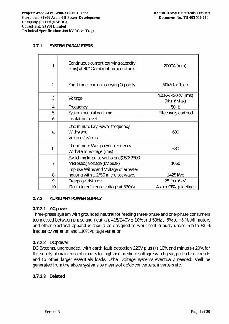
3.7.1 SYSTEM PARAMETERS
1 Continuous current carrying capacity (rms) at 40° C ambient temperature. 2000A (min)
2 Short time current carrying Capacity 50kA for 1sec
3 Voltage 400KV/420kV (rms) (Nom/Max)
4 Frequency 50Hz 5 System neutral earthing Effectively earthed 6 Insulation Level
a One minute Dry Power frequency Withstand Voltage (kV rms)
630
b One minute Wet power frequency Withstand Voltage (rms) 630
7 Switching Impulse withstand(250/2500 microsec.) voltage (kV peak) 1050
8 Impulse Withstand Voltage of arrester housing with 1.2/50 micro sec wave. 1425 kVp
9 Creepage distance 25 (mm/kV) 10 Radio Interference voltage at 320kV As per CEA guidelines
3.7.2 AUXILIARY POWER SUPPLY 3.7.2.1 AC power Three-phase system with grounded neutral for feeding three-phase and one-phase consumers (connected between phase and neutral), 415/240V ± 10% and 50Hz , -5% to +3 %. All motors and other electrical apparatus should be designed to work continuously under,-5% to +3 % frequency variation and ±10% voltage variation. 3.7.2.2 DC power DC Systems, ungrounded, with earth fault detection 220V plus (+) 10% and minus (-) 20% for the supply of main control circuits for high and medium voltage switchgear, protection circuits and to other larger essentials loads. Other voltage systems eventually needed, shall be generated from the above systems by means of dc/dc converters, inverters etc. 3.7.2.3 Deleted
Project: 4x225MW Arun-3 (HEP), Nepal Bharat Heavy Electricals Limited Customer: SJVN Arun -III Power Development Document No. TB 405 510 010 Company (P) Ltd (SAPDC) Consultant: SJVN Limited Technical Specification: 400 kV Wave Trap
Section-3 Page 5 of 39
3.7.2.4 Cabling & wiring Wiring within cubicles and equipment enclosures shall conform to requirements of this section unless otherwise specified. Control wiring shall be single / stranded copper subjected to prior approval by purchaser during detailed engineering and shall not be smaller than 2.5 Sq. mm, except as otherwise agreed by the purchaser. All Distribution Boards, Control & Protection panels, Motor Control control panels etc. shall be supplied completely wired internally up to the terminal blocks ready to receive purchaser control cable. All inter cubicle and inter panel wiring and connections between panels of same Distribution Board, Control & Protection panels, Motor Control panels including all bus wiring for AC and DC supplies shall be provided by the tenderer. Larger size wiring shall be used where needed for the current carrying capacity requirements. Cables shall have at least 1000 V PVC insulation except for 220V DC and telemetering or communication system equipment for which 650V and 300 V ratings respectively are acceptable. For current and potential transformer secondary circuits the minimum cross section of the conductors shall not be less than 4.0 Sq. mm. Wiring shall terminate at terminal blocks at one side only. Where tap connections are required, they shall be made on terminal blocks. Wiring shall be neatly arranged and laid in wire ways accessible from the front door. Engraved core identification ferrules marked to correspond with panel wiring diagram shall be fitted at both ends of each wire. Each cubical shall be provided with an earthing bar (PE) of sufficient cross section carrying any possible fault current without undue heating. All metallic parts of the cubicle not forming part of the live circuits, all instrument transformer terminals to be earthed and other earthing terminals as well as all cable screens and PE-wires shall be connected to the earthing bar. 3.7.2.5 Power outlets Power outlet for utilities such as electric drills, welding equipment etc., shall be provided in all floors of the powerhouse to enable repair and maintenance works to be done locally/ in-situ. 3.7.2.6 Terminal blocks The terminal blocks shall be located to allow a neat and easy connection work and shall be safely accessible while the equipment is in service. Control circuits and power circuits shall be completely separated by use of divided or separate terminal blocks. Power terminal blocks shall be rated in accordance with applicable standards, and shall be provided with covers.

Project: 4x225MW Arun-3 (HEP), Nepal Bharat Heavy Electricals Limited Customer: SJVN Arun -III Power Development Document No. TB 405 510 010 Company (P) Ltd (SAPDC) Consultant: SJVN Limited Technical Specification: 400 kV Wave Trap
Section-3 Page 6 of 39
Terminal blocks shall be 1100V grade and have continuous rating to carry the maximum expected current on the terminals. Terminal blocks for current transformer and voltage transformer secondary leads shall be provided with test links and isolating facilities. The current transformer secondary leads shall also be provided with short circuiting and earthing facilities. The terminal shall be such that maximum contact area is achieved when a cable is terminated. The terminal shall have a locking characteristic to prevent cable from escaping from the terminal clamp unless it is done intentionally. The conducting part in contact with cable shall preferably be tinned or silver plated. The terminal blocks shall be of extensible design. The terminal blocks shall have locking arrangement to prevent its escape from the mounting rails. The terminal blocks shall be fully enclosed with removable covers of transparent, non-deteriorating type plastic material. Insulating barriers shall be provided between the terminal blocks. These barriers shall not hinder the operator from carrying out the wiring without removing the barriers. Unless otherwise specified terminal blocks shall be suitable for connecting the following conductors on each side.
All circuits except CT/ PT flexible circuits
Minimum of two of 2.5 sq. mm copper
All CT/ PT Circuits flexible
Minimum of 2 nos. of 6 sq. mm copper
The arrangements shall be made in such a manner so that it is possible to safely connect or disconnect terminals on live circuits and replace fuse links when the cabinet is live. Wherever duplication of a terminal block is necessary it shall be achieved by solid bonding links. At least 20% spare terminals shall be provided on ach panel / cubicle / box and these spare terminals shall be uniformly distributed on all terminals rows. There shall be minimum clearance of 250 mm between the first / bottom row of terminal block and the associated cable gland plate. Also, the clearance between two rows of terminal blocks shall be a minimum of 150 mm.
Project: 4x225MW Arun-3 (HEP), Nepal Bharat Heavy Electricals Limited Customer: SJVN Arun -III Power Development Document No. TB 405 510 010 Company (P) Ltd (SAPDC) Consultant: SJVN Limited Technical Specification: 400 kV Wave Trap
Section-3 Page 7 of 39
3.7.2.7 Protection requirement For short circuit and overload protection of power and control circuits, air circuit breakers, moulded case circuit breakers or MCBs shall be used. Outlets from AC (and DC) distribution panels are protected in their respective panels. 3.7.2.8 Switches, Lamps & Instruments General Control switches, indicating lamps and instruments shall be arranged so that all parts are readily accessible for servicing without the necessity to remove other devices, terminal blocks or excessive amount of wiring. All control switches and indicating devices mounted in cabinets and enclosures shall be visible with the doors closed. Identification nameplates shall be provided for all control switches, indicating instruments and lamps, in accordance with clause “Nameplates”. Instruments and controls shall be located so that their dials, indicators and nameplates are clearly readable. Data for all instruments to be provided, including type, size, scale range, electrical ratings, nameplate and name of manufacturer, shall be furnished. Steel panels shall be provided for group mounting of the instruments. All instruments shall be of an approved type and shall match, insofar as practicable, the other instruments with which they are associated; their dial type, scaled markings and units, type of connection and mounting, shall be co-coordinated. All piping and tubing required for instruments shall be furnished and installed. All instruments and control switches shall be furnished with necessary auxiliaries,i.e. resistors, shunts etc. 3.7.2.9 Control and Selector switches The switches and push buttons shall be provided with ample contact ratings, suitable cam or block arrangements necessary for the control functions on 230 V AC or 220V DC circuits. The control switches used in mimic diagrams shall be of discrepancy type with built in lamp indication. Control and Selector switches shall be rotary type with escutcheon plates clearly marked to show the function and positions. The switches shall be of sturdy construction suitable for mounting on panel front. Switches with shrouding of live parts and sealing of contacts against dust ingress shall be provided. Circuit breaker control switches shall have three positions and shall be spring return to "NEUTRAL” from "CLOSE" and "TRIP" positions and shall have pistol grip handles. They shall have at least two (2) contacts closing in close position, and two (2) contacts closing in trip position unless specified otherwise. Ammeter and voltmeter selector switches shall have four stay out position with adequate number of contacts for three phase 4 wire system. These shall have oval handles. Ammeter selector switches shall have make before break type contacts to prevent open circuiting of CT
Project: 4x225MW Arun-3 (HEP), Nepal Bharat Heavy Electricals Limited Customer: SJVN Arun -III Power Development Document No. TB 405 510 010 Company (P) Ltd (SAPDC) Consultant: SJVN Limited Technical Specification: 400 kV Wave Trap
Section-3 Page 8 of 39
secondaries. Contacts of the switches shall be spring assisted and shall be of suitable material to give a long trouble free service. 3.7.2.10 Push buttons Push-buttons shall be of spring return, push to actuate type. Their contacts shall be rated to make, continuously carry and break 10A at 230V AC and 0.5A at 220V DC. All push buttons shall have one normally open and one normally closed contact, unless specified otherwise. The contact faces shall be of silver or silver alloy. All push buttons shall be provided with integral escutcheon plates marked with its function. The colour of the button shall be as follows: Green : Breaker Close Red : Breaker Open Black : For overload reset 3.7.2.11 Indicating and signaling lamps Each indicating and signaling lamp shall have a removable cap, which can be inscribed with wording and shall not be affected with the heat of the lamp. Indicating lamps are preferably of LED type & low watt consumption and shall be replaceable from the front of the panel. The indicating and signaling lamps shall be of the same size and type. Lamps shall be provided with series resistors, preferably built-in the lamps assembly. The lamps shall have escutcheon plates marked with its function, wherever necessary. Lamps shall have translucent lamp-covers of the following colours, as warranted by the application. Red : ACB's/MCCB's close Green : ACB's/MCCB's open White : Auto trip Amber : For all healthy conditions e.g. control supply Voilet : Circuit breaker spring charged Blue : For all alarm conditions (e.g. overload) Also for "SERVICE" & "TEST" positions indicators Indication lamps should be located just above the associated push buttons/control switches. All indicating lamps shall be suitable for continuous operation at 90% to 110% of their rated voltage. 3.7.2.12 HRC Fuses HRC-Fuses shall have visible operation indicators.
Project: 4x225MW Arun-3 (HEP), Nepal Bharat Heavy Electricals Limited Customer: SJVN Arun -III Power Development Document No. TB 405 510 010 Company (P) Ltd (SAPDC) Consultant: SJVN Limited Technical Specification: 400 kV Wave Trap
Section-3 Page 9 of 39
HRC-Fuses shall be mounted on fuses carriers, which are mounted on fuse bases. Wherever it is not possible to mount fuses on carriers, fuses shall be directly mounted on plug-in type of bases. In such cases one set of insulated fuse pulling handles shall be supplied with each switchgear. HRC-Fuse rating shall be chosen by the tenderer depending upon the circuit requirements. 3.7.2.13 Indicating instruments and Meters Instruments mounted on panels, shall be of the semi flush type back connected, matching pattern, shape, and of approved finish to present neat and fitting appearance consistent with functional requirements Mechanical quantity measuring instruments which are directly mounted on equipment shall have circular dials and shall be properly supported and guarded against accidental injury/breakage. These shall be placed in convenient locations. The instruments shall accurately measure and indicate the quantity under all conditions of operation with minimum instrument errors. Changes in ambient temperature within the range prevailing at site shall not affect the accuracy Contact making instruments shall have contacts suitable for 240 V AC or 220 V DC circuits. The reading scales on the dials shall be in metric units only and range shall be such that the normal operating values of the quantities are indicated in the middle 3rd of the scale. The dials pointer etc. shall be designed to facilitate accurate reading by minimizing parallax and glare from instrument window and by providing clear bold dial markings. The size of dial and length of the scales of the indicating instruments shall be large enough to suit the requirements. The scale plates of panel mounted indicating instruments shall have a permanent white mat finish with black graduations and the pointer shall also be of the black colour. Instruments mounted on panels shall be of flush type and shall be back connected. All instruments on a switchgear panel shall be of matching pattern, shape and finish so as to present a pleasing appearance consistent with the functional requirements. All instruments shall conform to relevant International or national applicable standards. These shall be subjected to tests prior to dispatch. The instruments shall be shock, vibration and moisture proof. The electrical instruments shall withstand dielectric test of 2000 V RMS to ground for one (1) minute as per standards. The coils of electrical instruments shall be designed for continuous operation at 110% of the full load current at instrument potential. The coil rating of the measuring instruments shall be coordinated with those of the associated instrument transformers (i.e. CTs, PTs, etc.) by the supplier. The VA burden of the instruments shall be as low as possible. The meters shall be of the first grade in respect of accuracy classification. Energy meter shall be suitable for 3-phase, 4-wire unbalanced system and shall comply generally with the relevant standard. All instruments shall be tested in accordance with the requirements of relevant standards. 3.7.2.14 Integrating instruments The Wh and VArh meters shall be of the semi-flush-mounted type. Each meter shall be connected to terminal blocks suitable for opening and short-circuiting for testing purposes. The meter cases shall be dust-tight and with removable covers. The meters shall be three-phase, three element, equipped with an impulse contact mechanism, potential free for

Project: 4x225MW Arun-3 (HEP), Nepal Bharat Heavy Electricals Limited Customer: SJVN Arun -III Power Development Document No. TB 405 510 010 Company (P) Ltd (SAPDC) Consultant: SJVN Limited Technical Specification: 400 kV Wave Trap
Section-3 Page 10 of 39
remote metering purposes, and shall be suitable for continuous operation from secondary of potential transformers and from secondary of current transformers, with transformer ratios and connections indicated on the contract drawings. The meters shall be provided with primary-rated, direct reading registers, with five or more digits and a suitable multiplier. The meters for the outgoing lines shall be of the two-way type and all meters shall have mechanism to prevent negative registration. The meters shall have built in over-voltage protection and isolation according to IEC Publication 60521. The tolerance ambient temperature range of the meters shall be 0 to 45 degrees C. The protection class of the Wh meters shall be 0.2 and the VArh meters 0.2 according to IEC Publication 60687. 3.7.2.15 Measuring converters The converters shall be suitable for direct connection to the secondary circuits of the potential and current transformers used, or other sensors, each as they apply. The converters shall be static type, having all accessories to provide an output signal of 4-20 mA, filtered DC. For the measuring converters the following minimum requirements shall be fulfilled: Current transducers shall be single-phase, of accuracy class 0.5 or better. Voltage transducers shall be single-phase of accuracy class 0.5 or better. W and VAR transducers shall be two elements, three-phase. Accuracy class of the transducers shall be 0.5 or better. 3.7.2.16 Measuring transformers All current and voltage transformers shall be completely encapsulated cast resin insulated type suitable for continuous operation at the temperature prevailing inside the switchgear enclosure, when the distribution board is operating at its rated condition and the outside ambient temperature is 40 deg.C. All instrument transformers shall be able to withstand the thermal and mechanical stresses resulting from the maximum short circuit and momentary current ratings of the associated switchgear. All instrument transformer shall have clear indelible polarity markings. All secondary terminals shall be wired to a separate terminal on an accessible terminal block where star-point formation and earthing shall be done. All VTs shall have readily accessible HRC current limiting fuses on both primary and secondary sides.The class of insulation should be E or better. The parameter & rating of CTs & PTs are minimum requirement & tentative only. Contactor shall submit the calculations for selection of CT/PT for approval to purchaser. Potential transformer secondary windings shall be rated 110 / V3 V Current transformer secondary windings shall have a rated current of 1A / 5A. 3.7.2.17 Nameplates and Labels Each major and auxiliary item of equipment shall have a nameplate permanently affixed thereto, or as directed, showing in a legible and durable manner the serial number, name and address of the manufacture, rated capacity, speed, electrical characteristics, and other significant information, as applicable.
Project: 4x225MW Arun-3 (HEP), Nepal Bharat Heavy Electricals Limited Customer: SJVN Arun -III Power Development Document No. TB 405 510 010 Company (P) Ltd (SAPDC) Consultant: SJVN Limited Technical Specification: 400 kV Wave Trap
Section-3 Page 11 of 39
The module identification plate shall clearly give the feeder number and feeder designation wherever applicable. For single front switchboards, similar panel and board identification labels shall be provided at the rear also. All name plates shall be of non rusting metal or 3-ply lamicoid with white engraved lettering on black back-ground, inscriptions and lettering sizes shall be as per their standard practice. Suitable plastic sticker labels shall be provided for easy identification of all equipment, located inside the panel/module. These labels shall be positioned so as to be clearly visible and shall give the device number, as mentioned in the module wiring drawings. 3.7.2.18 Motors All electric motors for driving various equipment shall conform to relevant standards viz. IEC, BS or IS as applicable. The motor rating, torque characteristics, speed etc. shall be selected to suit the duty requirements. Type of starter for motors shall be duly approved by the purchaser during detailed engineering. The detailed design calculation for selection of type of starters is to be submitted for approval. The priority for type of starters shall be in the following order: 1. Variable frequency drive 2. Soft starter 3. Star delta/ auto –transformer 4. Direct on-line starter The enclosure of each motor shall be of the type best suited for the service conditions of the motor.The motor insulation shall be resistant to moisture, oil or oil vapor and the motors in general shall be so designed as to suit the tropical climate. Varnished cambric or glass insulation class F shall be used for connection from the windings to the terminals. The terminal box shall be closed conduit box type conveniently located, and shall have means for terminating the external wiring for outdoor use. The motor terminals shall be of the stud type totally enclosed. Eye bolts or lugs shall be provided for lifting. Space heaters to avoid condensation shall also be provided. Special type of motors, not adequately covered by these specifications, shall be offered for any special application, but these shall be subject to the approval of purchaser. 3.7.2.19 Space heaters Space heater shall be provided in the Distribution Boards, Control & Protection panels, Motor Control panels etc. The space heaters shall be suitable for continuous operation on 240V AC, 50 HZ single phase supply, and shall be automatically controlled by thermostats. Necessary isolating switches and fuses shall also be provided. 3.7.2.20 Auxiliary relay, contacts and devices All relays and timers in protective circuits shall be flush mounted on panel front with connections from the inside. They shall have transparent dust tight covers removable from the front. All protective relays shall have a draw out construction for easy replacement from the front. They shall either have built-in test facilities, or shall be provided with necessary test blocks and test switches located immediately below each relay. The auxiliary relays and timers may be furnished in non-draw out cases. All AC auxiliary relays shall be suitable for operation with VTs and CTs secondaries.
Project: 4x225MW Arun-3 (HEP), Nepal Bharat Heavy Electricals Limited Customer: SJVN Arun -III Power Development Document No. TB 405 510 010 Company (P) Ltd (SAPDC) Consultant: SJVN Limited Technical Specification: 400 kV Wave Trap
Section-3 Page 12 of 39
DC auxiliary relays shall be designed for 220V DC unless otherwise specified and shall operate satisfactorily between 80% and 110% of the rated voltage. Relays shall have adequate thermal capacity for continuous operation in circuits in which they are used. All protective relays and timers shall have at least two potentially free output contacts. Relays shall have contacts as required for protection schemes. Contacts of relays and timers shall be silver faced and shall have a spring action. Adequate number of terminals shall be available on the relay cases for applicable relaying schemes. Suitable number of auxiliary contacts or auxiliary relays shall be provided with each VCB's / ACB’s for indication, remote indication, annunciation and automatic changeover and interlocking scheme. All protective relays, auxiliary relays and timers shall be provided with hand reset operation indicators (flag) for analysing the cause of operation. 3.7.2.21 Welding & NDT Preparation of base material Members to be joined by welding may be cut to shape and size by mechanical means such as shearing, machining, grinding, or by gas or arc cutting, to suit the conditions. Edges shall be shaped according to ASME requirements. Design of welded joints and selection of weld filler metal shall be in accordance with approved standards and shall allow thorough penetration and good fusion of the weld with the base metal. The edges of surfaces to be welded shall be sound metal free of visible defects such as laminations or defects caused by cutting operation at least 30 mm back from the edge of the weld, and free from rust, oil, grease, and other foreign matter. The establishment of welding procedures, welder’s qualifications shall conform to the requirements of the ASME Boiler and Pressure Vessel Code Section VIII and IX. The approved copy of the WPS & WPQR in accordance with the ASME requirements shall be submitted to the purchaser for review and record. 3.7.2.22 Field welding Filler material required for field-welded joints shall be furnished by the Contractor. The Contractor shall perform all welding work at site in accordance with the applicable WPS. Only qualified welders shall be used for undertaking welding as per the applicable WPS.NDT shall be performed as per the approved drawings. Preparation for field welding All cutting, chamfering, and other shaping of metals necessary for the field connection shall be done as far as possible in the shop. Adequate temporary bolted field connections shall be provided to hold the assemblies rigidly and in proper alignment during shop and field assembly. To ensure proper alignment during field erection, a minimum of two dowels shall be provided for each field connection between subassemblies. The holes shall be drilled and the dowels fitted at shop assembly after the subassemblies have been satisfactorily aligned. All stipulations for welding, structural work and other, shall be applied to fieldwork as well as to shop work, except where otherwise stated.
Project: 4x225MW Arun-3 (HEP), Nepal Bharat Heavy Electricals Limited Customer: SJVN Arun -III Power Development Document No. TB 405 510 010 Company (P) Ltd (SAPDC) Consultant: SJVN Limited Technical Specification: 400 kV Wave Trap
Section-3 Page 13 of 39
3.7.2.23 Painting All the equipment furnished and installed by the Contractor shall be completely painted for final use, with the exception of those parts or surfaces that are expressly designated as unpainted. Surfaces to be painted shall receive the preparatory treatment and required number of coats. The Contractor shall perform all painting work in the shop, before shipment, followed by a final coat of paint at site after installation as per the standard procedure. All materials, supplies, and articles furnished shall be the standard products of recognized reputable manufacturers.Colour schedule of equipment supplied shall be finalized during detailed design stage. 3.7.2.24 Galvanization All materials to be galvanized shall be of the full dimensions shown or specified and all punching, cutting, drilling, screw tapping and the removal of burrs shall be completed before the galvanizing process commences. All galvanizing shall be done by the hot dip process with smelter, not less than ninety eight percent (98%) of which must be pure zinc. No alternative process shall be used without the approval of the purchaser. No components shall be galvanized which are likely to come into subsequent contact with oil. Bolts shall be completely galvanized including the threads, but the threads shall be left uncoated in the case of nuts. The zinc coating shall be uniform, clean, smooth and as free from spangle as possible. In the case of component parts the zinc coating shall weigh not less than 0.6 kg/m2 over the area covered and be not less than 0.09mm in thickness. All galvanizing shall comply with the requirements of the relevant ASTM standards/Indian Standards. All galvanized parts shall be protected from injury to the zinc coating due to differential aeration and abrasion during the period of transit, storage and erection. Damaged areas of the coating shall be touched up with an approved zinc dust paint or other approved flake metallic compound.
3.7.2.25 Pumps All pumps forming part of the generating units and other plant and equipment shall be of high performance requisite type (viz. centrifugal, rotary etc.) and rating, of reputed make, and shall be directly coupled to their driving motors. The pumps shall be of self-priming type and with proper sealing systems and protection. The materials of construction of pumps in general shall suit the service conditions. The materials of construction of the pumps handling water, such as drainage & dewatering pumps, turbine top cover drainage pumps etc. shall be resistant to abrasive effects of silt in such water. The pumps shall operate quietly without undue noise and vibration in their full operating range of head and flow. They shall be easy to maintain. 3.7.2.26 Embedded parts, Anchor Bolts and Fasteners All embedded anchor bolts, rods, pipes, welding plates and support plates shall be provided by contractor. Anchor bolts shall consist of a threaded steel rod installed inside a pipe sleeve to provide lateral adjustment after the sleeve is embedded. The threaded end of the rod shall be provided with two steel nuts and two steel washers to permit leveling and anchoring the equipment prior to grouting. Approved types of expansion or chemical anchors shall be used where practicable for small equipment.

Project: 4x225MW Arun-3 (HEP), Nepal Bharat Heavy Electricals Limited Customer: SJVN Arun -III Power Development Document No. TB 405 510 010 Company (P) Ltd (SAPDC) Consultant: SJVN Limited Technical Specification: 400 kV Wave Trap
Section-3 Page 14 of 39
3.7.2.27 Rust Prevention and Protection during Transit:- Bright steel parts including all machined surfaces shall be given a thick coat of tar or tallow or any other approved rust resisting paint in plain colour to prevent rusting during shipment and transport. 3.7.2.28 Civil Works Civil foundations for equipment of the generating units and other plant and equipment will be prepared by the Purchaser in accordance with the basic design data to be supplied by the Contractor. The Contractor shall provide design for foundations and install the concrete inserts/embedment; support steels and/or components for foundation /supports purpose, shall do any chipping / levelling works, denting / painting etc. 3.7.3 Erection, Testing, Commissioning and performance of Guarantee Tests
3.7.3.1 Testing and inspection Materials used for construction of major & important sub-assemblies shall be thoroughly shop tested and inspected by the Contractor at his own expense prior to dispatch. Shop test shall comprise of routine test & type tests. The shop tests and inspections shall be as spelt out in individual equipment specifications as dealt in succeeding sections but shall not be limited to the same. Any other tests and inspection not specifically listed but are otherwise considered essential and advisable shall also be conducted. The Bidders shall furnish schedule of the shop tests and inspections on materials and equipment. Important tests/inspections shall be subject to witness by the purchaser for which the Contractor shall give sufficient advance notice. In case purchaser is unable to witness shop tests/inspections, the Contractor shall be so intimated and the tests/inspections may then be carried out in the absence of the Purchaser. Equipment on which tests and inspections have been duly witnessed and approved by the Purchaser may be dispatched by the Contractor. Equipment on which tests and inspections have not been witnessed by the purchaser shall be dispatched only after the shop tests and inspection Certificates have been approved by the Purchaser. 3.7.3.2 Dimensional Checks and Visual Inspection
Dimensional checks shall be performed on all major parts, components and partial assemblies, especially when close tolerances and fits are involved (tolerance of shafts, between stationary and moving parts, connecting dimensions for the assembly with other supplies, etc.). If the dimensional checks show discrepancies in measurement, which may affect the fit, assembly or dismantling of the respective part or component, the same have to be corrected correspondingly. Such correction or modification shall, however, in no way lead to sacrifices with respect to reliability of operation or inter-changeability, and shall be performed only after the agreement of the Owner has been obtained. If the correction or modification cannot be carried out in accordance with the terms mentioned above, the part
Project: 4x225MW Arun-3 (HEP), Nepal Bharat Heavy Electricals Limited Customer: SJVN Arun -III Power Development Document No. TB 405 510 010 Company (P) Ltd (SAPDC) Consultant: SJVN Limited Technical Specification: 400 kV Wave Trap
Section-3 Page 15 of 39
or component concerned may be subject to rejection. Faulty machine parts or equipment shall by no means be delivered. 3.7.3.3 Functional Tests Functional tests on partial assemblies and/or complete assemblies shall be carried out as much as possible already in the manufacturer's workshops. Such tests shall be performed as far as possible under operation-like conditions. When requested by the Owner, the functional tests shall be repeated until full proof has been obtained that the functioning of the assemblies will comply with the requirements of the Contract Documents. 3.7.3.4 Erection, commissioning & field tests The Contractor has to do all the work related to assembly, erection, testing and commissioning complete in all respects. All necessary tools, plants, labour, materials including consumables for performing installation, testing and pre-commissioning shall be provided by the Contractor. The Contractor shall submit the necessary data/information, layout and foundation/support drawings well in advance. The Contractor shall provide and install the concrete inserts/embedment, support steels and/or components for foundation/supports purpose as per approved erection drawings and coordinate the activities with civil contractors to keep his activities in synchronism with civil work. All installation for foundation shall be verified and accepted by the Engineer. The Contractor shall use anchor fasteners for installation of piping, fixtures, mountings, conduits, cabling, panels etc. Minor Chipping of concrete is permitted. However, taking support from reinforcement bars shall not be allowed.
3.7.3.5 Installation procedure The Contractor shall submit six copies of all detailed programs and the procedures to be adopted for erection / installation, testing and commissioning well in advance, before start of erection activities/ installation. The installation procedure shall also have a section “site quality assurance plan” containing erection data sheets / site protocols for various components. These sheets should specify site measurements/ inspections required to be made for ensuring proper installation. 3.7.3.6 Cable laying Wiring between equipment enclosures shall be made with cables, laid in trenches and/or cable trays and in cable conduits. The Contractor shall submit for review to the Engineer a cable route layout-showing location of trenches, conduits and trays. All material for cable laying such as cable trays supports and fastening material shall be furnished and placed by the Contractor. Cables shall be properly fastened and marked where they enter enclosures by either cable clamps or nipples. Cables in horizontal cable trays shall be fastened properly with clamps or plastic strips. Power and control cables shall be placed in separate trays or conduits. Cables shall be clearly marked at each terminal point and appropriate intermediate locations as per Standard.
Project: 4x225MW Arun-3 (HEP), Nepal Bharat Heavy Electricals Limited Customer: SJVN Arun -III Power Development Document No. TB 405 510 010 Company (P) Ltd (SAPDC) Consultant: SJVN Limited Technical Specification: 400 kV Wave Trap
Section-3 Page 16 of 39
Conduits shall be of heavy gauge rigid steel, hot-dip galvanized, cut square reamed, threaded and screwed tight at all joints. Conduit entrances to pull boxes and switches shall have double lock nuts & insulating bushings. No running thread shall be used. Flexible metallic conduit shall be used for connection to equipment, which are subject to vibration, and also for connection to level/limit/pressure switches. 3.7.3.7 Field inspection The Contractor shall permit Engineer to perform inspections of the assembly which will include a complete verification of the assembly of all parts as to their levels, clearances, pertinent fits, alignments and quality of workmanship. The field supervisor of the Contractor shall provide Engineer with three (3) copies of all the clearances, tolerances and data of all pertinent fits, alignments and levels, so that the latter may repeat the Contractor’s measurement, if desired. Unless otherwise specified, any rejection based on the inspection will be reported to Contractor within fifteen (15) days. 3.7.3.8 Field tests All field tests including tests during installation, pre-commissioning, commissioning, performance and field acceptance tests shall be conducted by the Contractor, in the presence of representative of the Employer. Procedure to be adopted for conducting these tests shall be submitted well in advance, before start of relevant testing, for approval of the Employer. The equipment / system shall be deemed to be commissioned and ready for trial run only after successful operation for a test service period specified in sub clause “Performance Testing”. In the event of any failure this period shall be repeated for any number of times till the successful operation as described above is achieved. All test equipment and instruments shall be furnished by the Contractor and will remain the Contractor’s property after the fulfillment of all field tests. Any defects or leaks disclosed in the tests shall be duly mended/ repaired to meet the desired function and retested. All necessary materials and labour for performing all the above tests shall be provided by the Contractor. The Contractor shall prepare written test certificates in a form agreed upon by the Contractor and Employer of all tests results and hand them over to the Employer in due time. The design, location and approval tests of anchoring rings for the fixing of lifting apparatus necessary for assembly and dismantling of equipment and plant accessories shall be the responsibility of the Contractor. 3.7.3.9 Taking over of facilities Taking over” means that the Facilities (or a specific part thereof where specified) have been completed operationally and structurally and put in a tight and clean condition, and that all work in respect of pre-commissioning of the Facilities or such specific part thereof has been completed and commissioning has been attained as per Technical Specifications. The contractor shall make formal request for taking over the facility to the EIC.
Project: 4x225MW Arun-3 (HEP), Nepal Bharat Heavy Electricals Limited Customer: SJVN Arun -III Power Development Document No. TB 405 510 010 Company (P) Ltd (SAPDC) Consultant: SJVN Limited Technical Specification: 400 kV Wave Trap
Section-3 Page 17 of 39
3.7.3.10 Operation acceptance The operational acceptance by the Employer of the Facilities (or any part of the Facilities where the Contract provides for acceptance of the Facilities in parts), which certifies the Contractor’s fulfillment of the Contract in respect of Functional Guarantees of the Facilities (or the relevant part thereof) in accordance with the provisions of Specification. 3.7.3.11 Consumables, oils and Lubricant The Contractor shall deliver to the Owner all equipment complete with initial fill of fluids, grease or lubricants, transformer oil, Nitrogen, SF6 gas and other used gases in non returnable drums / containers and replace any quantity used up or lost during installation and testing. The oil used for the lubrication and oil pressure systems for the turbine, governor, shutoff valve and generator shall be preferably of the same type.
Supply The Contractor shall furnish the following: (i) All oil for initial filling of all equipment supplied, plus additional oil equivalent to the first filling requirement of one unit. (ii) Grease if required for initial filling of all of the equipment, plus 10% additional. (iii) Gases for initial filling of all equipment supplied, plus 10 % additional quantity. (iv) Flushing fluids to flush and clean all systems. 3.7.3.12 Deleted:
3.7.3.13 Submission of Drawings, Documents, Manual, software, Calculations, Safety Margin Details etc.
All drawings and documents shall be submitted to purchaser in hard form as well as in editable soft form. Bidder shall submit Ten (10) number hard copies of the documents & drawings to purchaser for reference / review / approval. A comprehensive list of all such drawings/documents planned to be submitted for reference/approval shall be provided beforehand to the purchaser. Loading drawings For all larger pieces of Works which, due to their dimensions and/or weight and transport limitations, will require special means for their transportation, the Contractor shall submit binding loading drawings indicating dimensions, weights, etc., of the respective pieces of Works and the necessary trailer for its transportation to the site. Foundation drawings If a piece of works requires its own foundation or needs a special area for installation, the contractor shall submit drawings indicating all pertinent dimensions, static and dynamic loads, etc. They shall include all essential details required for proper design and construction of the foundations and/or buildings. In addition, they shall include openings, sleeves, slopes and the arrangement of any supporting structure, i.e. base-frames or other steel constructions for permanent fixing or erection purposes.

Project: 4x225MW Arun-3 (HEP), Nepal Bharat Heavy Electricals Limited Customer: SJVN Arun -III Power Development Document No. TB 405 510 010 Company (P) Ltd (SAPDC) Consultant: SJVN Limited Technical Specification: 400 kV Wave Trap
Section-3 Page 18 of 39
If conduits are to be installed in the foundations, the relevant information such as diameter, length, and purpose shall be indicated on the drawings. Arrangement drawings All arrangement drawings shall be drawn to scale. The General Arrangement Drawings shall show the physical arrangement of Works (constructions, machines, complete switchgears, control panels, instrument cubicles, etc.), civil constructions (buildings, rooms, foundations, ducts, etc.) and reserved areas (for pipes, cables, lines, etc.) in relation to each other and to agreed co-ordinates and boundaries. Such drawings shall be prepared for the whole plot, for separate plots and for each building (building, hall, room, ducts and trenches, etc.). Outline drawings The Outline Drawing shall show all elements and the main dimensions of individual components where necessary in plan view, cross-section, side and top views. If reasonably possible such dimensions can be shown on Arrangement Drawings. Design drawings The Design Drawings shall include the shop drawings, assembly drawings, erection drawings, piping diagrams and piping arrangement drawings, etc., showing the dimensions, design and data of all constructions, apparatus and Works to be furnished under this Contract. The drawings shall - where applicable - substantially conform to the Contract Drawings and shall show: • 3-D Assembly drawings for major components in hard and soft form. • Details of manufacturing and treatment of major single work pieces specially manufactured
for this Contract • Assembly of the Works in plan and elevation with main dimensions Sub-assembly of the
principal components of the Works with overall dimensions, adjustment and clearance tolerances, numbers of corresponding detail drawings
• Sub-assemblies in which the Contractor proposes to ship the Works • All necessary details of the parts connecting to the Works supplied by others • Location and sizes of auxiliary connections for oil, grease, water, air, electrical power etc. • Location and size of the instruments and accessories provided • Methods of lubrication and sealing • Instructions for heat treatment, pressure tests, surface preparation and anticorrosive
protection • Full details of parts for which adjustment is provided or which are subject to wear • Method and sequence of installation, field joints, erection and lifting devices, jacks, grout
plugs, anchoring details, etc., if not shown on foundation drawings.
Installation drawings The construction, mechanical, electrical and I & C Installation Drawings shall provide detailed information on the disposition of the various items of a system (e.g. lighting fixtures, socket outlets, connection boxes, transmitters, actuators, loudspeakers, telephones, pipes, valves, pumps, compressors, etc.) and of the piping and wiring respectively included in the
Project: 4x225MW Arun-3 (HEP), Nepal Bharat Heavy Electricals Limited Customer: SJVN Arun -III Power Development Document No. TB 405 510 010 Company (P) Ltd (SAPDC) Consultant: SJVN Limited Technical Specification: 400 kV Wave Trap
Section-3 Page 19 of 39
installation or assembly. They shall be based on dimension drawings of cubicles, rooms, buildings or areas containing the Works. Diagrams
Single-line diagrams This is a simplified diagram of the essential electrical Works and their interconnections. Each circuit shall be represented by a single line only. It shall contain all required technical information of the Works represented, e.g. voltage, current, capacity, shortcircuit level, ratios, voltage variations, positive and zero sequence impedances, measuring transformer and protection relay indices, interlocking, kind of switch drive, code designation, etc. as applicable. Circuit diagrams The Circuit Diagrams shall show the power circuits in all the phases with the main apparatus as well as the pilot circuits (measuring and control circuits). It shall show in full the functioning of part or all installations, Works or circuits with all required technical details. Block diagrams The Block Diagrams shall be used to show in a simplified manner the main inter - relationships between the elements of a system by means of symbols, block symbols and pictures without necessarily showing all the connections. The symbols used for the individual kinds of components, e.g. servomotors, computing modules, etc., shall clearly be explained on the diagram or on an attached legend. Logic diagrams The Logic or Functional Diagrams shall be used for representation of logic and sequence controls and interlocking by showing only binary logic elements and their effect on the various process equipment disregarding their electrical realisation. Logic function elements (AND, OR, NOR, NAND, STORAGE, etc.) shall be used for processing and combining binary signals. Terminal diagrams Such diagrams shall be prepared for any type of terminal box, marshalling rack, control cubicle, switchboard, etc., and shall show the terminals (properly numbered) and the internal and/or external conductors (wires or cables) connected to them. The terminal diagram of each individual switchboard, terminal box, panel, etc., shall contain, but not be limited to the following information: Protection co-ordination diagrams These diagrams shall show in a graphical manner separately for each power supply circuit: • A simplified single-line diagram of the circuit with technical data of all instrument
transformers and relays • Co-ordinated tripping curves of related protection devices • Setting of the protection devices.
Emergency shutdown diagram
Project: 4x225MW Arun-3 (HEP), Nepal Bharat Heavy Electricals Limited Customer: SJVN Arun -III Power Development Document No. TB 405 510 010 Company (P) Ltd (SAPDC) Consultant: SJVN Limited Technical Specification: 400 kV Wave Trap
Section-3 Page 20 of 39
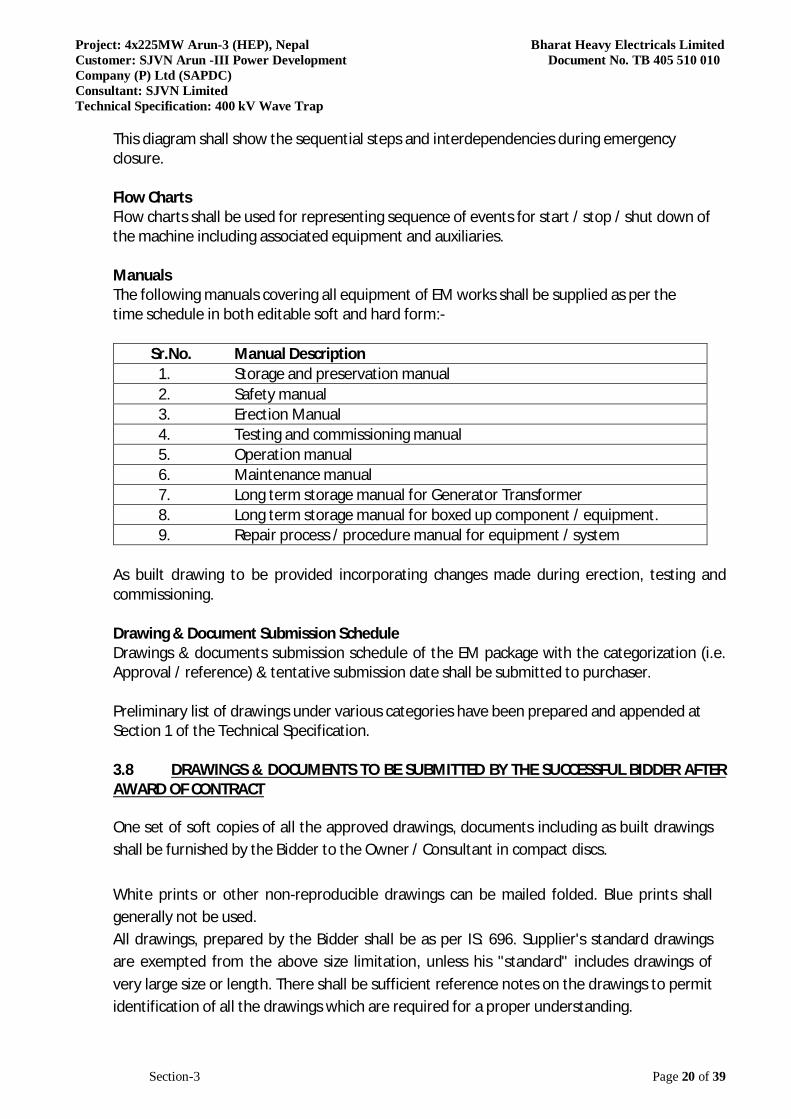
This diagram shall show the sequential steps and interdependencies during emergency closure. Flow Charts Flow charts shall be used for representing sequence of events for start / stop / shut down of the machine including associated equipment and auxiliaries. Manuals The following manuals covering all equipment of EM works shall be supplied as per the time schedule in both editable soft and hard form:-
Sr.No. Manual Description 1. Storage and preservation manual 2. Safety manual 3. Erection Manual 4. Testing and commissioning manual 5. Operation manual 6. Maintenance manual 7. Long term storage manual for Generator Transformer 8. Long term storage manual for boxed up component / equipment. 9. Repair process / procedure manual for equipment / system
As built drawing to be provided incorporating changes made during erection, testing and commissioning. Drawing & Document Submission Schedule Drawings & documents submission schedule of the EM package with the categorization (i.e. Approval / reference) & tentative submission date shall be submitted to purchaser. Preliminary list of drawings under various categories have been prepared and appended at Section 1 of the Technical Specification. 3.8 DRAWINGS & DOCUMENTS TO BE SUBMITTED BY THE SUCCESSFUL BIDDER AFTER AWARD OF CONTRACT One set of soft copies of all the approved drawings, documents including as built drawings shall be furnished by the Bidder to the Owner / Consultant in compact discs. White prints or other non-reproducible drawings can be mailed folded. Blue prints shall generally not be used. All drawings, prepared by the Bidder shall be as per IS: 696. Supplier's standard drawings are exempted from the above size limitation, unless his "standard" includes drawings of very large size or length. There shall be sufficient reference notes on the drawings to permit identification of all the drawings which are required for a proper understanding.
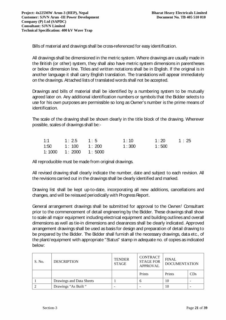
Project: 4x225MW Arun-3 (HEP), Nepal Bharat Heavy Electricals Limited Customer: SJVN Arun -III Power Development Document No. TB 405 510 010 Company (P) Ltd (SAPDC) Consultant: SJVN Limited Technical Specification: 400 kV Wave Trap
Section-3 Page 21 of 39
Bills of material and drawings shall be cross-referenced for easy identification. All drawings shall be dimensioned in the metric system. Where drawings are usually made in the British (or other) system, they shall also have metric system dimensions in parentheses or below dimension line. Titles and written notations shall be in English. If the original is in another language it shall carry English translation. The translations will appear immediately on the drawings. Attached lists of translated words shall not be accepted. Drawings and bills of material shall be identified by a numbering system to be mutually agreed later on. Any additional identification numbers or symbols that the Bidder selects to use for his own purposes are permissible so long as Owner's number is the prime means of identification. The scale of the drawing shall be shown clearly in the title block of the drawing. Wherever possible, scales of drawings shall be:-
1:1 1 : 2.5 1 : 5 1 : 10 1 : 20 1 : 25 1:50 1 : 100 1 : 200 1 : 300 1 : 500 1: 1000 1 : 2000 1 : 5000
All reproducible must be made from original drawings. All revised drawing shall clearly indicate the number, date and subject to each revision. All the revisions carried out in the drawings shall be clearly identified and marked. Drawing list shall be kept up-to-date, incorporating all new additions, cancellations and changes, and will be reissued periodically with Progress Report. General arrangement drawings shall be submitted for approval to the Owner/ Consultant prior to the commencement of detail engineering by the Bidder. These drawings shall show to scale all major equipment including electrical equipment and building outlines and overall dimensions as well as tie-in dimensions and clearances shall be clearly indicated. Approved arrangement drawings shall be used as basis for design and preparation of detail drawing to be prepared by the Bidder. The Bidder shall furnish all the necessary drawings, data etc., of the plant/equipment with appropriate "Status" stamp in adequate no. of copies as indicated below:
S. No. DESCRIPTION TENDER STAGE
CONTRACT STAGE FOR APPROVAL
FINAL DOCUMENTATION
Prints Prints CDs
1 Drawings and Data Sheets 1 6 10 - 2 Drawings “As Built “ - - 10 -
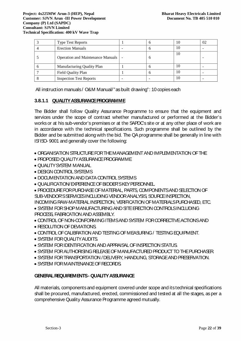
Project: 4x225MW Arun-3 (HEP), Nepal Bharat Heavy Electricals Limited Customer: SJVN Arun -III Power Development Document No. TB 405 510 010 Company (P) Ltd (SAPDC) Consultant: SJVN Limited Technical Specification: 400 kV Wave Trap
Section-3 Page 22 of 39
3 Type Test Reports 1 6 10 02 4 Erection Manuals - 6 10 -
5 Operation and Maintenance Manuals - 6 10
-
6 Manufacturing Quality Plan 1 6 10 - 7 Field Quality Plan 1 6 10 - 8 Inspection Test Reports - - 10 -
All instruction manuals / O&M Manual/”as built drawing”: 10 copies each
3.8.1.1 QUALITY ASSURANCE PROGRAMME
The Bidder shall follow Quality Assurance Programme to ensure that the equipment and services under the scope of contract whether manufactured or performed at the Bidder’s works or at his sub-vendor’s premises or at the SAPDC’s site or at any other place of work are in accordance with the technical specifications. Such programme shall be outlined by the Bidder and be submitted along with the bid. The QA programme shall be generally in line with IS/ISO- 9001 and generally cover the following: ORGANISATION STRUCTURE FOR THE MANAGEMENT AND IMPLEMENTATION OF THE PROPOSED QUALITY ASSURANCE PROGRAMME QUALITY SYSTEM MANUAL DESIGN CONTROL SYSTEMS DOCUMENTATION AND DATA CONTROL SYSTEMS QUALIFICATION/EXPERIENCE OF BIDDER’S KEY PERSONNEL. PROCEDURE FOR PURCHASE OF MATERIAL, PARTS, COMPONENTS AND SELECTION OF SUB-VENDOR’S SERVICES INCLUDING VENDOR ANALYSIS, SOURCE INSPECTION, INCOMING RAW-MATERIAL INSPECTION, VERIFICATION OF MATERIALS PURCHASED, ETC. SYSTEM FOR SHOP MANUFACTURING AND SITE ERECTION CONTROLS INCLUDING PROCESS, FABRICATION AND ASSEMBLY. CONTROL OF NON-CONFORMING ITEMS AND SYSTEM FOR CORRECTIVE ACTIONS AND RESOLUTION OF DEVIATIONS. CONTROL OF CALIBRATION AND TESTING OF MEASURING / TESTING EQUIPMENT. SYSTEM FOR QUALITY AUDITS. SYSTEM FOR IDENTIFICATION AND APPRAISAL OF INSPECTION STATUS. SYSTEM FOR AUTHORISING RELEASE OF MANUFACTURED PRODUCT TO THE PURCHASER. SYSTEM FOR TRANSPORTATION /DELIVERY, HANDLING, STORAGE AND PRESERVATION. SYSTEM FOR MAINTENANCE OF RECORDS. GENERAL REQUIREMENTS - QUALITY ASSURANCE All materials, components and equipment covered under scope and its technical specifications shall be procured, manufactured, erected, commissioned and tested at all the stages, as per a comprehensive Quality Assurance Programme agreed mutually.

Project: 4x225MW Arun-3 (HEP), Nepal Bharat Heavy Electricals Limited Customer: SJVN Arun -III Power Development Document No. TB 405 510 010 Company (P) Ltd (SAPDC) Consultant: SJVN Limited Technical Specification: 400 kV Wave Trap
Section-3 Page 23 of 39
Minimum Quality Assurance Test Requirement (QATR) to be followed during Manufacturing and Field erection indicating requirement of various tests / inspections, on major equipment / items, to be carried out as stipulated in technical specification and standards mentioned therein, are attached hereto and are part of bidding documents. Clarification, if any, on these quality assurance test requirement, raised by bidder shall be discussed and resolved during pre-bid meeting. After the award of contract, the contractor shall submit the detailed Manufacturing & Field Quality Assurance Plans for complete equipment / material during detailed engineering in the format attached hereto (format of quality plan F-060-02 issue 2.0 rev. 01, Total 1 Page) for approval and acceptance by SAPDC/Consultant in line with technical specification, Quality Assurance – General & Test Requirements and detailed engineering. Manufacturing Quality Assurance Plans shall detail out for all the components and equipment & various tests/inspection, to be carried out in conformity with relevant latest IEC/IS/ISO etc, quality practices and procedures to be followed by Contractor’s / Subvendor’s Quality Control Organization, the relevant reference documents, standards and acceptance norms etc. during all stages of material procurement, manufacture, assembly and final testing / factory acceptance tests. The Field Quality Assurance Plans shall detail out the various tests/inspection to be carried out in conformity with relevant latest IEC/IS/ISO, quality practices and procedures etc. to be followed by the contractor’s / sub-contractor’s site Quality Control Organisation during various stages of site activities from receipt of material/equipment at site till final commissioning/ acceptance/handover. All major items/ equipment/ components to be manufactured in house as well as procured from sub-vendors (Bought out Items, BOI) to be listed in the bid. Bidder shall submit Quality Assurance Plan submission schedule in the bid for above listed items in attached Format (duly filled in the format F-060-05 Issue 2.0 Rev. 00, Total 1 Page) in line with L2 Schedule. For components / equipment / Bought out Items procured by the contractor for the purpose of the contract, the Contractor’s purchase specifications and inquiries shall call for quality plans to be submitted by the sub-vendors. The quality plans called for from the sub-vendors shall detail out, during the various stages of manufacture and installation, the quality practices and procedures followed by the sub-vendor’s quality control organisation, the relevant reference documents/standards used, acceptance level, inspection of documentation raised, etc. Such quality plans of the successful sub-vendors shall be finalized with the SAPDC/Consultant in line with requirement mentioned above and such approved Quality Plans shall form a part of the purchase order/contract between the contractor and his sub-vendor.
Project: 4x225MW Arun-3 (HEP), Nepal Bharat Heavy Electricals Limited Customer: SJVN Arun -III Power Development Document No. TB 405 510 010 Company (P) Ltd (SAPDC) Consultant: SJVN Limited Technical Specification: 400 kV Wave Trap
Section-3 Page 24 of 39
Within three weeks of the release of the purchase orders /contracts for such bought out items /components, a copy of the same without price details but together with the detailed purchase specifications and other related documents such as data sheet, drawings, quality plans and delivery conditions shall be furnished to the SAPDC/Consultant by contractor along with a report of the Purchase Orders placed, on the monthly basis, so far for the contract. The Quality Plans shall be submitted on electronic media e.g. CD or E-mail in addition to hard copy, for review and approval of SAPDC/Consultant. After approval, the same shall be submitted in compiled form on CD-ROM by contractor. For all spares, replacement items and additional similar items, the quality requirements/Quality Plans as agreed for the main equipment supply shall be applicable. All material of construction shall be as per technical specification / approved drawings / GTP. Contractor’s Plant internal standards must be traceable to acceptable International / National standards & salient points of difference (if any) shall be clearly stated with submission of plant standards. The contractor shall furnish copies of reference documents, plant standards, acceptance norms, test and inspection procedure etc. as referred in Quality Plans along with Quality Plan to SAPDC/Consultant. These Quality Plans and reference documents/standards etc. will be subject to approval of SAPDC without which manufacturer shall not proceed. These documents shall form a part of the contract. Tests on components and sub-assemblies shall be carried out at various stages of manufacturing, till the product undergoes the final tests in conformity with the relevant standards. The Customer Hold Points (CHPs), identified in approved quality plan, i.e. testing checks which shall be carried out in the presence of the SAPDC, beyond which the work will not proceed without written consent of SAPDC’s authorized representative. The contractor / sub-vendor shall carry out routine test on 100% items at his works. The quantum of check / test for routine and acceptance test by SAPDC/Consultant shall be generally as per criteria / sampling plan defined in referred standards. Wherever standards have not been mentioned, quantum of check / test for routine / acceptance test shall be as agreed during detailed engineering. The quantum of check when specified in percentage (%) / sampling basis shall be treated as per lot per sub-vendor. When the quantum of check is indicated to in whole no., then same quantum of check shall be applicable to each sub-vendor supplying the same equipment. For sub-vendors identified during pre-award stage for submission of vendor details/ credentials (category “DR”), contractor shall submit documents in format F-060-01 after placement of award in the manner as specified as under prior to any procurement and within a month after placement of award or a period as agreed at the time of pre-award discussions.
Project: 4x225MW Arun-3 (HEP), Nepal Bharat Heavy Electricals Limited Customer: SJVN Arun -III Power Development Document No. TB 405 510 010 Company (P) Ltd (SAPDC) Consultant: SJVN Limited Technical Specification: 400 kV Wave Trap
Section-3 Page 25 of 39
The proposed sub-vendors should be registered vendors of the bidder and must have proven experience for successful operation for similar equipment / items / processes as mentioned elsewhere in technical specification. Before assigning any portion of work to the sub-vendor, other than one specified and duly accepted in the contract, the contractor will take prior approval of BHEL/SAPDC. Normally no request for change of sub-vendors or inclusion shall be entertained by SAPDC. But in exceptional circumstances, if the request for change of sub-vendors or inclusion is found reasonable and justified, then the same shall be entertained and the decision of SAPDC in this respect shall be final and binding. The time consumed for the change / inclusion of sub-vendors shall not be excluded from the stipulated time of the completion of the contract. This change shall not relieve the contractor from the responsibility to complete the work within stipulated time in any manner. The contractor’s proposal shall include sub-vendor’s facilities established at the respective works, the process capability, process stabilization, Q.C. system followed, experience list etc. along with his own technical evaluation of sub-vendor. (Format F- 060-01 issue 2.0 rev. 01, Supplier / Sub-vendor Assessment Sheet, Total 14 pages). However, whenever felt necessary, sub-vendor assessment will also be carried out by SAPDC/Consultant in accordance with the above procedure and by factory visits; for existing/proposed vendors/sub-vendors. This approval shall not relieve the contractor from any obligation, duty or responsibility under the contract & SAPDC shall not be responsible for any complications arising between the contractor and his subcontractor(s) / sub-vendor (s) and / or any other liabilities. SAPDC/Consultant reserves the right to carry out quality audit and quality surveillance of the system and procedures of the contractor / or their sub-vendor. The contractor shall provide all necessary assistance to enable SAPDC/Consultant to carry out such details & surveillance including Quality Manuals, if required by SAPDC/Consultant. All welding and brazing shall be carried out as per procedure drawn and qualified in accordance with requirement of ASME section-VIII/IX or other International equivalent standard acceptable to SAPDC/Consultant. All welding/brazing procedures shall be submitted to SAPDC/Consultant/BHEL for review / verification prior to carrying out the welding/brazing. However, wherever required by the SAPDC/Consultant, tests shall be conducted in presence of SAPDC’s authorized representative. All Brazers, Welders and welding operators employed on any part of the contract either in Contractor/his sub-vendor’s works or at site or elsewhere shall be qualified as per ASME section-VIII/IX or other equivalent International Standards acceptable to SAPDC/Consultant. Unless otherwise proven and specifically agreed with SAPDC/Consultant, welding of dissimilar material and high alloy materials shall be carried out at shop only.
Project: 4x225MW Arun-3 (HEP), Nepal Bharat Heavy Electricals Limited Customer: SJVN Arun -III Power Development Document No. TB 405 510 010 Company (P) Ltd (SAPDC) Consultant: SJVN Limited Technical Specification: 400 kV Wave Trap
Section-3 Page 26 of 39
All non-destructive examination shall be performed in accordance with written procedures as per International Standards. The NDT operator shall be qualified as per SNT-TC-IA (of the American or Indian Society of non-destructive examination). NDT shall be recorded in a report, which include detail of methods and equipment used, result/evaluation, job data and identification of personnel employed and details of correlation of the test report with the job. All material used for equipment manufacture including castings and forgings, etc. shall be of tested quality as per relevant codes/standards. Details of results of the tests conducted to determine the mechanical properties; chemical analysis and details of heat treatment procedure recommended and actually followed shall be recorded on certificates and time temperature chart. Tests shall be carried out as per applicable material standards and/or agreed details. Contractor shall submit Field Welding Schedule for field welding activities like field welding location, numbers, welding procedure to be used, requirements, codes and NDT requirement along with all supporting documents, like welding procedures, heat treatment procedures, NDT procedures, etc. to SAPDC/Consultant for review at least ninety days before schedule start of erection work at site. Any other statutory requirements as applicable for the equipment / systems shall also be complied with. The inspection calls (duly filled in the format F-060-06 Issue 2.0 Rev. 00, total 1 Page) shall be placed at least 06 weeks in advance for overseas inspections excluding India and 15 days in advance for inspections within India and Nepal. Before submitting the inspection call to SAPDC for witnessing the Customer Hold Points (CHP’s) and/or requesting SAPDC for issuance of Material Dispatch Clearance Certificate (MDCC) based on Test Certificate (TC) review / Certificate of Conformance (COC), the contractor shall ensure that all Drawings / documents / GTP / technical data sheet, relevant to respective CHP / MDCC requirement, has been duly approved /accepted / noted by SAPDC. Contractor shall ensure readiness of offered equipment by all means, before raising such call to SAPDC to attend CHP inspections. In case, SAPDC engineer (s) on reaching at a place of inspection found that material is not ready for inspection due to whatsoever reason, the complete inspection expenditure of SAPDC engineer(s) as per actual shall be chargeable to the contractor. Only calibrated testing & measuring instruments shall be used while performing tests during manufacturing and erection, testing & commissioning at site by the contractor. Copy of the calibration certificates will be submitted to SAPDC/Consultant by the contractor during inspection as an evidence. Non-conformities observed during manufacturing, shop testing, handling, packaging, transportation, storage, preservation, erection, testing & commissioning are required to be intimated by the contractor (Format for reporting, F-060-04 issue 2.0 rev 01, Total 5 pages). The acceptance/rejection of the non-conformities will be at the discretion of SAPDC.
Project: 4x225MW Arun-3 (HEP), Nepal Bharat Heavy Electricals Limited Customer: SJVN Arun -III Power Development Document No. TB 405 510 010 Company (P) Ltd (SAPDC) Consultant: SJVN Limited Technical Specification: 400 kV Wave Trap
Section-3 Page 27 of 39
Repair/rectification procedures to be adopted to make the job acceptable shall be subject to the acceptance of SAPDC. Action taken in accordance with decision of disposal of non-conformity for repair / rework / modification of the item / equipment and to prevent re-occurrence. The corrective and preventive action may involve modification of item / equipment, change in procedure and system etc. to achieve quality improvement at all stages and levels. Quality audit/surveillance/approval of the results of the tests and inspection will not, however, prejudice the right of the SAPDC to reject the equipment if it does not comply with the specification when erected or does not give complete satisfaction in service and the above shall in no way limit the liabilities and responsibilities of the Contractor in ensuring complete conformance of the materials/equipment supplied to relevant specification, standard, data sheets, drawings etc. No material shall be dispatched from the manufacturer’s works before the same is duly accepted, subsequent to pre dispatch/final inspection including verification of records of all previous tests/inspection by SAPDC and duly authorised for Dispatch by issuance of Material Dispatch Clearance Certificate (MDCC). The test reports of type tests conducted as per contract, in line with requirement stipulated in the technical specification / quality plan should be got accepted from SAPDC/Consultant before final inspection / issuance of MDCC. All materials used or supplied shall be accompanied by valid and approved material certificates and tests and inspection reports. These certificates and reports shall indicate the heat numbers or other such acceptable identification numbers of the material. The material certified shall also have the identification details stamped on it to ensure physical correlation and traceability of material vis-a-vis test certificate. Such identification no. shall remain same and verifiable for all stages of manufacturing and installation. 3.8.1.2 QA DOCUMENTATION The contractor shall be required to submit the QA Documentation in two hard copies and two CD ROMs, as identified in respective quality plan. Each QA Documentation shall have a project specific Cover Sheet bearing name and identification number of equipment including index of its contents with page control on each document. The QA Documentation file shall be progressively completed by the Contractor/sub-vendor to allow regular reviews by all parties during the manufacturing. The final quality document will be compiled and issued at the final assembly place of equipment before despatch. However CD-ROM may be issued not later than three weeks. Before dispatch / commissioning of any equipment, the Contractor shall make sure that the corresponding quality document or in the case of protracted phased deliveries, the applicable
Project: 4x225MW Arun-3 (HEP), Nepal Bharat Heavy Electricals Limited Customer: SJVN Arun -III Power Development Document No. TB 405 510 010 Company (P) Ltd (SAPDC) Consultant: SJVN Limited Technical Specification: 400 kV Wave Trap
Section-3 Page 28 of 39
section of the quality document file is completed. The Contractor will then notify the Inspector regarding the readiness of the quality document (or applicable section) for review. The contractor shall be required to submit copies of the following quality assurance documents in original duly reviewed and accepted by contractor along with the request letter for issuance of MDCC (Material Dispatch Clearance Certificate): QUALITY PLAN CHECK LIST. MATERIAL MILL TEST REPORTS ON COMPONENTS AS SPECIFIED IN QUALITY PLAN. SKETCHES AND DRAWINGS USED FOR INDICATING THE METHOD OF TRACEABILITY OF THE RADIOGRAPHS TO THE LOCATION ON THE EQUIPMENT. NON-DESTRUCTIVE EXAMINATION RESULTS REPORTS INCLUDING INTERPRETATION
REPORTS. CALIBRATION CERTIFICATE OF ALL METERS & MEASURING INSTRUMENTS PROPOSED TO BE SUPPLIED AS PART OF RELEVANT BILLING BREAKUP ITEM. ROUTINE TEST REPORTS FOR TESTING REQUIRED AS PER APPLICABLE CODES AND STANDARDS REFERRED IN THE SPECIFICATIONS. INSPECTION REPORTS DULY SIGNED BY AUTHORIZED REPRESENTATIVE OF SAPDC AND CONTRACTOR FOR THE AGREED CUSTOMER HOLD POINTS. ALL THE ACCEPTED DEVIATIONS SHALL BE INCLUDED WITH COMPLETE TECHNICAL DETAILS. LIST OF BALANCE POINTS IF ANY. CERTIFICATES IN RESPECT OF CALIBRATION, WELDERS & BRAZERS QUALIFICATION ETC. COPY OF ALL REFERENCE DRAWINGS AND REFERENCE TECHNICAL DOCUMENTS ACCEPTANCE OF TYPE TEST REPORTS BY SAPDC/CONSULTANT. Similarly, the Contractor shall be required to submit two sets (two hard copies and two CD ROMs), containing QA Documentation pertaining to field activities as per Approved Field Quality Plans and other agreed manuals/procedures, within 2 weeks after commissioning of individual system. On release of QA Documentation by Inspector, one set of quality document shall be forwarded to Consultant and other set to SAPDC. For the particular case of phased deliveries, the complete quality document to the SAPDC/Consultant shall be issued not later than 3 weeks after the date of the last delivery of equipment. ASSOCIATED DOCUMENTS / FORMATS • F-060-01 VENDOR / SUB-VENDOR ASSESSMENT SHEET • F-060-02 QUALITY PLAN SUBMISSION BY CONTRACTOR. • F-060-04 NON-CONFORMANCE REPORT (NCR) • F-060-06 INSPECTION CALL REQUEST. 3.8.1.3 Safety Safety of personnel
Project: 4x225MW Arun-3 (HEP), Nepal Bharat Heavy Electricals Limited Customer: SJVN Arun -III Power Development Document No. TB 405 510 010 Company (P) Ltd (SAPDC) Consultant: SJVN Limited Technical Specification: 400 kV Wave Trap
Section-3 Page 29 of 39
All equipment and services provided under this contract shall abide by international standards commonly accepted in the hydroelectric utility industry for safety of personnel whether involved with operation or maintenance. Safety of operation All equipment and services provided under this contract shall abide by commonly accepted standards for safety of operation. The various system and sub-systems supplied under this contract shall be designed to follow and operate under a clear hierarchical structure: • Plant control level, • Unit control level, • Functional control level, functional drive group level, • Local drive level. Each hierarchical control level shall perform its specific tasks and always depend on the subordinate lower control levels. In general, should a higher control level failure occur, the lower control level shall not be affected and shall be able to control the power plant with full safety. The Contractor shall accordingly build into the "Electrical & Mechanical System" adequate levels of autonomy, independence, redundancy and functional distribution to insure that safety is maintained at all times. 3.8.1.4 Earthing Earthing terminals for equipment of these specifications shall form part of equipment supplies. The contractor shall connect the earthing conductors to these terminals as required. Risers from earthing bus shall be in the scope of purchaser. However, extension from these risers to the equipment shall be in the scope of supplier in the Power House, Transformer Hall, Switchyard and Butterfly Valve House. However, overall earthing arrangement required for HT panel, LT panel, DG set, motor & motor control panels etc. at isolated location such as Dam Site, TRT Outfall area and Surge Shaft either by pit earthing or counter poise etc. shall be in the scope of supplier including civil works, design, material supply (for main earthing risers, interconnection, charcoal, salt, Bentonite etc.), erection, testing & commissioning etc. A copper ground bus, sized to carry maximum short circuit current, shall run along the entire length of panel structure and shall have terminal connector at each end for connection to station ground grid (50 X 6 mm G.I. flat). Tests Each panel shall be completely assembled, wired, adjusted and tested at the factory prior to shipment. The test shall include wiring continuity tests, insulation tests and functional tests to ensure satisfactory operation and control of individual equipment.
Project: 4x225MW Arun-3 (HEP), Nepal Bharat Heavy Electricals Limited Customer: SJVN Arun -III Power Development Document No. TB 405 510 010 Company (P) Ltd (SAPDC) Consultant: SJVN Limited Technical Specification: 400 kV Wave Trap
Section-3 Page 30 of 39
Special Cables Special cables for specific purpose, as required, shall be supplied and installed by the Bidder. 3.8.1.5 Completeness of the specification Any fittings, accessories, equipment or any other things required for successful commissioning of Arun-III Hydro Electric Project, though may not have been specifically mentioned in the specification but are usually necessary for the completeness of the equipment shall be deemed to be included in the specification and shall be supplied by the contractor without any extra cost to the Employer. 3.8.1.6 Packaging and Shipment The Contractor shall provide such packing of the Goods as it is required to prevent their damage or deterioration during transit to their final destination as indicated in the Contract. The packing shall be sufficient to withstand, without limitation, rough handling during transit and exposure to extreme temperatures, salt and precipitation during transit and open storage. Packing case size and weights shall take into consideration, where appropriate, the remoteness of the final destination of Goods and the absence of heavy handling facilities at all points in transit. The packing, marking and documentation within and outside the packages shall comply strictly with such special requirements as shall be expressly provided for in the Contract and, subject to any subsequent instruction ordered by the Employer consistent with the requirements of the Contract. After unpacking of Goods the packing material shall become the property of Employer The contractor shall wrap, pack and crate all plant included in the work or part thereof, suitable for shipment to a tropical location, facilitating proper handling and protection from damage in rail, truck, ocean or air shipment as applicable. An approved drying agent, such as Silica Gel, shall be packed in containers or packages holding plant which may be adversely affected by moisture or excessive humidity. All packing crates shall be clearly marked before shipping to indicate the contract number, shipping address, volume, weight, name, number and unit number of the contents, slinging and weight bearing points. All plant parts shall be marked to facilitate erection. Each packing crate shall contain a packing list in a waterproof envelope. Parts shall be described and also identified by their numbered marking in the packing list. Three copies of the packing list shall be forwarded to the purchaser prior to dispatch. The ownership of packaging materials shall be of Employer. All wooden packaging crates and steel support structures shall be dumped to the designated area within 5kms of the power house as per the direction of Engineer in charge. The supplier shall be entirely responsible for the insurance, shipment, handling and transportation.
Project: 4x225MW Arun-3 (HEP), Nepal Bharat Heavy Electricals Limited Customer: SJVN Arun -III Power Development Document No. TB 405 510 010 Company (P) Ltd (SAPDC) Consultant: SJVN Limited Technical Specification: 400 kV Wave Trap
Section-3 Page 31 of 39
The equipment shall not be dispatched by the Bidder from the place of manufacture to the site until the dispatch instructions are issued by the Owner. 3.8.1.7 PACKAGING, HANDLING AND SITE STORAGE
The Contractor shall pack all the consignment in sea worthy packaging strong enough to withstand rough handling during transit. Machine surface shall be suitably protected against scratches, corrosion, shocks, impact etc. Packages shall be suitably and distinctly identified for type of handling and kind of storage. Electronic equipment shall be packaged, shipped and stored in anti-static packing. All packages shall be stored indoor. Packages containing electronic equipment shall be stored in humidity controlled environment. The Bidder shall indicate the number of packages of consignment together with the size (L x W x H) and weight for transporting the equipment in the Bidding Document. 3.9 SPECIAL INSTRUCTIONS TO BIDDERS General The Bidder shall base the equipment design on the information given in this specification. The equipment shall be complete in all respects. Any item which is not specifically mentioned herein but found essential for safe and efficient operation and maintenance and satisfactory performance of the system shall be deemed to have been included in the scope of the Bidder. It shall be presumed that the Bidder has studied the site, all the drawings, tender documents and is fully aware of the scope of work involved and the site conditions prevailing. 3.10 Codes and Standards a) All equipment, systems and works covered under this specification shall comply, in all
respect, with requirements of applicable latest statutes and that of latest editions of codes and standards. Latest regulations and safety & environmental requirements as applicable in India / state of installation shall also be complied with.
b) All codes and standards mentioned shall mean as relevant and applicable to a particular
equipment / system. c) All other codes/standards not covered in Section 1 / Section 2 but required for the plant
and system offered shall also be referred / followed by the Bidder. The Bidder, along with the bid, shall submit a comprehensive list of codes and standards to be followed for various equipment / system.
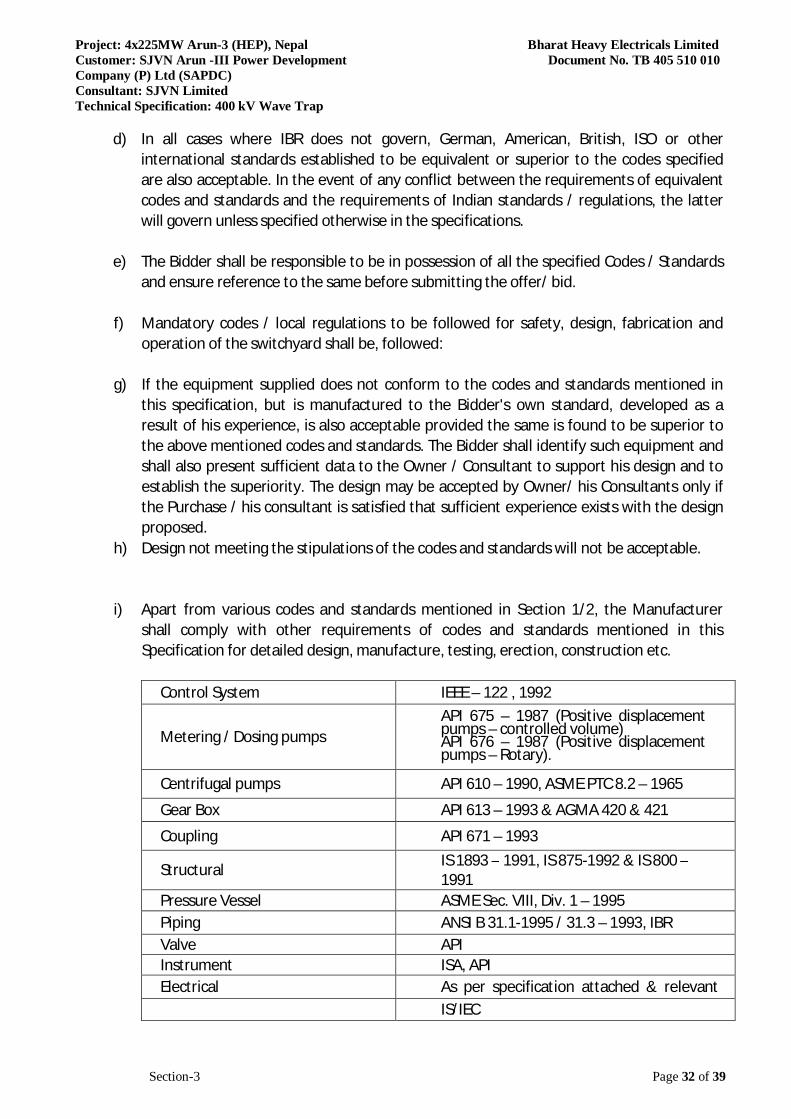
Project: 4x225MW Arun-3 (HEP), Nepal Bharat Heavy Electricals Limited Customer: SJVN Arun -III Power Development Document No. TB 405 510 010 Company (P) Ltd (SAPDC) Consultant: SJVN Limited Technical Specification: 400 kV Wave Trap
Section-3 Page 32 of 39
d) In all cases where IBR does not govern, German, American, British, ISO or other international standards established to be equivalent or superior to the codes specified are also acceptable. In the event of any conflict between the requirements of equivalent codes and standards and the requirements of Indian standards / regulations, the latter will govern unless specified otherwise in the specifications.
e) The Bidder shall be responsible to be in possession of all the specified Codes / Standards
and ensure reference to the same before submitting the offer/ bid. f) Mandatory codes / local regulations to be followed for safety, design, fabrication and
operation of the switchyard shall be, followed: g) If the equipment supplied does not conform to the codes and standards mentioned in
this specification, but is manufactured to the Bidder's own standard, developed as a result of his experience, is also acceptable provided the same is found to be superior to the above mentioned codes and standards. The Bidder shall identify such equipment and shall also present sufficient data to the Owner / Consultant to support his design and to establish the superiority. The design may be accepted by Owner/ his Consultants only if the Purchase / his consultant is satisfied that sufficient experience exists with the design proposed.
h) Design not meeting the stipulations of the codes and standards will not be acceptable. i) Apart from various codes and standards mentioned in Section 1/2, the Manufacturer
shall comply with other requirements of codes and standards mentioned in this Specification for detailed design, manufacture, testing, erection, construction etc.
Control System IEEE – 122 , 1992
Metering / Dosing pumps API 675 – 1987 (Positive displacement pumps – controlled volume) API 676 – 1987 (Positive displacement pumps – Rotary).
Centrifugal pumps API 610 – 1990, ASME PTC 8.2 – 1965
Gear Box API 613 – 1993 & AGMA 420 & 421
Coupling API 671 – 1993
Structural IS 1893 – 1991, IS 875-1992 & IS 800 – 1991
Pressure Vessel ASME Sec. VIII, Div. 1 – 1995 Piping ANSI B 31.1-1995 / 31.3 – 1993, IBR Valve API Instrument ISA, API Electrical As per specification attached & relevant IS/IEC

Project: 4x225MW Arun-3 (HEP), Nepal Bharat Heavy Electricals Limited Customer: SJVN Arun -III Power Development Document No. TB 405 510 010 Company (P) Ltd (SAPDC) Consultant: SJVN Limited Technical Specification: 400 kV Wave Trap
Section-3 Page 33 of 39
Tanks API 650- 1993 Electrodes AWS, IS Painting IS Standards
Performances Tests
Overload test of crane and hoists IS 3177
3.11 Deviations and Assumptions Bidders requested to carefully examine and understand the specifications and seek clarifications, if required, to ensure that they have understood the specifications. The Bidder's offer should not carry any sections like clarifications, interpretations and/or assumptions. In the event of conflict between the Technical Specifications and the condition of contract, the requirements as indicated in the technical specification shall govern, unless confirmed otherwise by the Owner in writing before the award of contract, based on written request from the bidder for such a clarification. In the event of conflict between requirements of any two clauses of the specification documents, the more stringent requirements shall apply, unless otherwise confirmed by the Owner in writing before the award of this contract, based on a written request from the Bidder for such clarification. The Bidders are advised that while making their Bid Proposals and quoting prices, all terms and conditions of bidding documents may appropriately be taken into consideration. Bidders are required to furnish a certificate indicating their full compliance to the terms and conditions of the bidding documents. 3.12 Limit of Contract Equipment furnished shall be complete in all respect with all mountings, fittings, fixtures and standard accessories normally provided with such equipment and/ or needed for erection, completion and safe operation of the equipment as required by applicable codes though they may not have been specifically detailed in the respective specifications, unless included in the list of exclusions. All similar standard components/ parts of similar standard equipment provided shall be interchangeable with one another. This review by the Owner’s Engineer / Consultant may not indicate a thorough review of all dimensions, quantities and details of the equipment, materials, any devices or items indicative of the accuracy of the information submitted. This review and/ or approval by the Engineer shall not be construed by the Bidder, as limiting any of his responsibilities and liabilities for mistakes and deviations from the requirements specified under these specifications and documents. 3.13 Latent Defects Notwithstanding the issue of the Take Over Certificate, the Contractor shall be responsible for making good with all possible speed any Latent Defect in any Works /equipment of the plant which appears at any time before the expiry of defect liability period. And shall remedy such
Project: 4x225MW Arun-3 (HEP), Nepal Bharat Heavy Electricals Limited Customer: SJVN Arun -III Power Development Document No. TB 405 510 010 Company (P) Ltd (SAPDC) Consultant: SJVN Limited Technical Specification: 400 kV Wave Trap
Section-3 Page 34 of 39
defect at its own cost and expense. The latent defect liability period shall be a minimum of 5 years from the end of defect liability period. The defects to which this applies are defects in design, materials or workmanship or defects arising from any act or omission of the Contractor done or omitted prior to Take-over of the portion of the Plant affected by the defects or during the Warranty Period which a reasonable examination at the end of the Warranty Period would not have disclosed. 3.14 Defect Liability
The Contractor warrants that all the facilities or any part thereof are new, unused, and of the most recent or current models, and that they incorporate all recent improvements in design and materials, unless provided otherwise in the Contract. The Contractor further warrants that the Plant and equipment shall be free from defects arising from any act or omission of the Contractor or arising from design, materials, and workmanship, under normal use in the conditions prevailing in the If during the Defect Liability Period any defect should be found in the design, engineering, materials and workmanship of the Plant and equipment supplied or part thereof, the Contractor shall promptly, in consultation and agreement with the Employer regarding appropriate remedying of the defects, and at its cost, repair, replace or otherwise make good (as the Contractor shall, at its discretion, determine) such defect as well as any damage to the Facilities caused by such defect. The Contractor shall not be responsible for the repair, replacement or making good of any defect or of any damage to the Facilities arising out of or resulting from any of the following causes: (a) Improper operation or maintenance of the Plant and equipment by the Employer (b) Operation of the Facilities outside specifications provided in the Contract (c) Normal wear and tear. 3.15 Completion Schedule The Bidder shall submit Time Bar chart indicating completion date of major activities such as submission of design data / calculations and drawings for approval, manufacturing of components / units, supply, inspection etc. without which the Tender shall not be considered. Time Bar Chart furnished shall afterwards form part of the contract and cannot be altered arbitrarily except Force Majeure conditions as may be agreed with the Owner. 3.16 Drawings & Documents for Owner’s use and Archives The Bidder shall submit all final drawings, documents, manuals for Owner’s use and for reference / record required during course of operation and maintenance of the plant. Numbers of copies and their form (hard copy, electronic form, reproducible) to be submitted and the details of the documents, drawings, manual etc. to be furnished by the Bidder are described elsewhere in the specification. Drawings, documents, calculation, data & Information to be submitted by the Bidder along with the offer:
Project: 4x225MW Arun-3 (HEP), Nepal Bharat Heavy Electricals Limited Customer: SJVN Arun -III Power Development Document No. TB 405 510 010 Company (P) Ltd (SAPDC) Consultant: SJVN Limited Technical Specification: 400 kV Wave Trap
Section-3 Page 35 of 39
Technical Data to be submitted with the Tender
1) List of performance tests proposed by the Bidder to demonstrate the guaranteed parameters for generator and other electrical equipment.
2) Specific energy consumption. 3) Type test certificates for major categories of equipment, issued by independent
testing authority. 4) Guaranteed Technical Parameters. 5) Technical catalogues. 6) Manufacturing Quality Plan
Operation & Maintenance Manuals Instruction manuals, presenting the basic categories of information for the operating and/or maintenance personnel, as detailed herein below shall be furnished by Bidder. The instruction manuals shall present the following basic categories of information in particular complete and comprehensive manner and prepared for the use by operating and/or maintenance personnel.
i. Instructions for initial commissioning, short duration and long duration shut down. ii. Instruction for operation, routine inspection and maintenance including preventive
maintenance. iii. Recommendation for inspection points, method of inspection and period of inspection. iv. Information on detection, cause and rectification of troubles and faults. v. Instructions on normal repairs and overhaul. vi. Complete parts list with proper and complete identification (Tag nos./Serial nos. as
shown in the respective approved drawings) and ordering information for all replaceable parts. The identification details of equivalent and alternative makes for these spare parts which are not manufacturer's own product shall also be listed.
vii. List of all special tools and tackle & spares and instructions for use of such tools and tackle & spares.
viii. One complete set of as built drawings of the entire systems. ix. The information shall be organized in a logical and orderly sequence. A general
description of equipment including significant technical characteristics shall be included to familiarize operating and maintenance personnel with the equipment. Such description and technical characteristics shall not differ from the approved data.
x. Necessary drawings, curves and other illustrations shall be included or copies of appropriate approved drawings shall be bound in the manuals. Tests, adjustment and calibration information, as appropriate, shall be included. Safety and other warning notices and installation, maintenance and operating cautions shall be emphasized.
xi. Write-up, figures, part list etc., shall be clearly legible. The manuals shall be prepared on good quality paper securely bound in durable folders.
xii. The instruction manuals shall be subject to Consultant's approval in the same fashion as that for drawings.
xiii. Instruction manual shall give step by step procedure for Erection, testing and commissioning
Project: 4x225MW Arun-3 (HEP), Nepal Bharat Heavy Electricals Limited Customer: SJVN Arun -III Power Development Document No. TB 405 510 010 Company (P) Ltd (SAPDC) Consultant: SJVN Limited Technical Specification: 400 kV Wave Trap
Section-3 Page 36 of 39
xiv. Operation, Maintenance and Repair Instruction manual shall also contain: xv. List of spare parts with ordering specifications and manufacturer's catalogues xvi. List of consumables, lubricants, chemicals with specifications, brand names and annual
consumption figures. xvii. Drawings relevant for erection, operation, maintenance and repair of the equipment. xviii. Procedure for ordering spares. xix. Maintenance Manual shall also include: xx. Diagnostic trouble shooting / fault location charts xxi. Tests for checking of proper functioning.
Drawings / documents for approval Quality Control & Quality Assurance plan. G.A. and Cross Sectional drawings of all equipment indicating weights, material of construction, bill of material, dimension, specification etc. Final design calculations and assumptions. Actual performance data and characteristic curves based on the testing at site. Technical specification of all equipment, motors, for all system and all other accessories. Final list of drawings. As built drawings.
Miscellaneous
i. General arrangement and cross sectional drawings of all major components with bill of material.
ii. Foundation drawings, load data & design calculation for all equipment.
iii. Erection drawings for all equipment and structures showing complete erection details.
iv. Engineering and design calculations of installations and units.
v. QAPs
vi. Detailed procedures of shop testing of all the items applicable shall be submitted to the
Owner/ Consultant for approval before conducting tests. vii. Following shop test certificates/test curves/data, shall be furnished.
Materials and components test certificates. Performance test results and characteristic curves of all fans, pumps, and electric
drive motors etc. Non-destructive test results as applicable. Reports and test certificates of shop tests. Type test & routine test certificates.
viii. Detailed quality assurance program along with quality plan shall be submitted.
Project: 4x225MW Arun-3 (HEP), Nepal Bharat Heavy Electricals Limited Customer: SJVN Arun -III Power Development Document No. TB 405 510 010 Company (P) Ltd (SAPDC) Consultant: SJVN Limited Technical Specification: 400 kV Wave Trap
Section-3 Page 37 of 39
Following data shall be furnished:-
a) Technical data of all the plant, equipment, drive motors, instruments, panels, etc. shall be furnished.
b) Following lists/tables / write ups shall be furnished, complete with tag nos. and brief
specification. Proper numbering system as approved by Consultant/Owner shall be adopted.
i) Instrument schedule (with service, range, make of instrument). ii) Flow element schedule. iii) Valve schedule. iv) Pipe schedule. v) Cable schedule (Power & Control). vi) Schedule of actuators (electric/pneumatic)
The scheduled dates for the submission of these as well as for, any data/information to be furnished by the Employer would be discussed and finalized at the time of award. The supplier shall also submit required no. of copies as mentioned in this specification of all drawings/design documents/test reports for approval by the Employer.
Note: The contractor may please note that all resubmissions must incorporate, all comments given in the submission by the Employer failing which the submission of documents is likely to be returned. Every revision shall be a revision number, date and subject, in a revision block provided in the drawing, clearly marking the changes incorporated. 3.17 Workmanship and Quality Control All moving parts of equipment, which can conceivably cause injury to the operator and otherwise authorized personnel within the vicinity of working area shall be suitably guarded and warning displays shall be put at prominent places. The Bidder shall clearly indicate and identify the plans and procedures, which shall be followed in the design, manufacture and installation of plant and equipment to control and assure to the Owner of the desired quality. FUNGI STATIC VARNISH Besides the space heaters, special moisture and fungus resistance varnish shall be applied on parts which may be subjected or predisposed to the formation of fungi due to the presence or deposit of nutrient substances. The varnish shall not be applied to any surface of part where the treatment will interfere with the operation or performance of the equipment. Such surfaces or parts shall be protected against the application of the varnish.
Project: 4x225MW Arun-3 (HEP), Nepal Bharat Heavy Electricals Limited Customer: SJVN Arun -III Power Development Document No. TB 405 510 010 Company (P) Ltd (SAPDC) Consultant: SJVN Limited Technical Specification: 400 kV Wave Trap
Section-3 Page 38 of 39
3.17.1 Equipment Mounting All instruments, switches etc. mounted on the front face of the panels shall be of flush type. All equipment shall be so mounted that removal and replacement may be accomplished individually without interruption of service to others. All equipment inside the panel shall be so located that their terminals and adjustments are readily accessible for inspection and maintenance. Adequate ventilation shall be provided in enclosed panel. Each of the LV switchboards shalll be designed for 1.1 times the required rating as a spare capacity. Further all LV Switchboard shall be provided with 20 % spare modules of each rating and type of module.
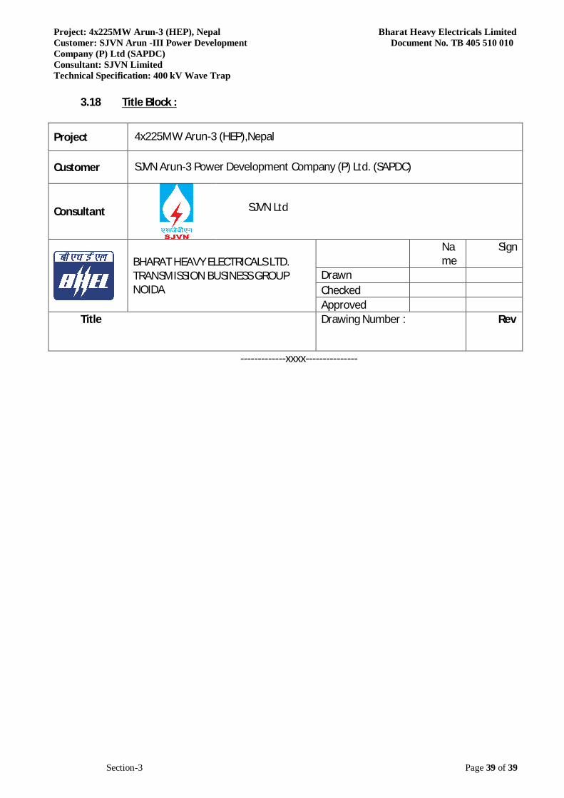
Project: 4x225MW Arun-3 (HEP), Nepal Bharat Heavy Electricals Limited Customer: SJVN Arun -III Power Development Document No. TB 405 510 010 Company (P) Ltd (SAPDC) Consultant: SJVN Limited Technical Specification: 400 kV Wave Trap
Section-3 Page 39 of 39
3.18 Title Block :
Project 4x225MW Arun-3 (HEP),Nepal
Customer SJVN Arun-3 Power Development Company (P) Ltd. (SAPDC)
Consultant
SJVN Ltd
BHARAT HEAVY ELECTRICALS LTD. TRANSMISSION BUSINESS GROUP NOIDA
Name
Sign
Drawn Checked Approved
Title Drawing Number : Rev
-------------xxxx---------------
Project: 4x225MW Arun-3 (HEP), Nepal Customer: SJVN Arun -III Power Development Company (P) Ltd (SAPDC) Consultant: SJVN Limited Technical Specification: 400 kV Wave Trap
Bharat Heavy Electricals Limited Document No. TB 405 510 010
WAVE TRAPS 400 kV
1 Name of manufacturer and country :
2 Type Model and Catalogue No :
3 System Voltage Rating :
4 Continuous current rating at 50o C ambient :
5 Continuous current rating at 65o C ambient :
6 Maximum Symmetrical short circuit current rating for :1 sec Duration
7 Asymmetric peak value of first half wave of rated short time :current
8 Rated Inductance :
9 Blocking Range :
10 Minimum Guaranteed Resistive Component in Blocking :frequency range
11 Type of Tuning :
12 Variation in 50Hz Impedance per Degree Centigrade :variation in ambient temperture
13 Variation in Resonant frequency band per degree centigrade :variation in ambient temperature
14 Details of protection of capacitors and coils against voltage :surges indicate type of protective device.
15 Basic Insulation level :
16 Standard Nominal Discharge Current of Protective Device :for 8/20 Micro second wave impulse
17 Rated voltage of the Arrestor (Protective device) :
18 Min. value of power frequency sparkover voltage (Dry and :wet) of protective devices
19 Maximum 1.2/50 usec Impulse Sparkover voltage of :protective device
SECTION-4GUARANTEED TECHNICAL PARTICULARS
1 OF 3
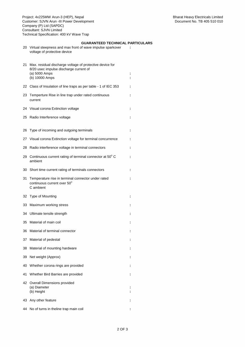
Project: 4x225MW Arun-3 (HEP), Nepal Customer: SJVN Arun -III Power Development Company (P) Ltd (SAPDC) Consultant: SJVN Limited Technical Specification: 400 kV Wave Trap
Bharat Heavy Electricals Limited Document No. TB 405 510 010
GUARANTEED TECHNICAL PARTICULARS20 Virtual steepness and max front of wave impulse sparkover :
voltage of protective device
21 Max. residual discharge voltage of protective device for8/20 usec impulse discharge current of(a) 5000 Amps :(b) 10000 Amps :
22 Class of Insulation of line traps as per table - 1 of IEC 353 :
23 Temperture Rise in line trap under rated continuous :current
24 Visual corona Extinction voltage :
25 Radio Interference voltage :
26 Type of incoming and outgoing terminals :
27 Visual corona Extinction voltage for terminal concurrence :
28 Radio interference voltage in terminal connectors :
29 Continuous current rating of terminal connector at 50o C :ambient
30 Short time current rating of terminals connectors :
31 Temperature rise in terminal connector under rated :continuous current over 50o
C ambient
32 Type of Mounting :
33 Maximum working stress :
34 Ultimate tensile strength :
35 Material of main coil :
36 Material of terminal connector :
37 Material of pedestal :
38 Material of mounting hardware :
39 Net weight (Approx) :
40 Whether corona rings are provided :
41 Whether Bird Barries are provided :
42 Overall Dimensions provided(a) Diameter :(b) Height :
43 Any other feature :
44 No of turns in theline trap main coil :
2 OF 3
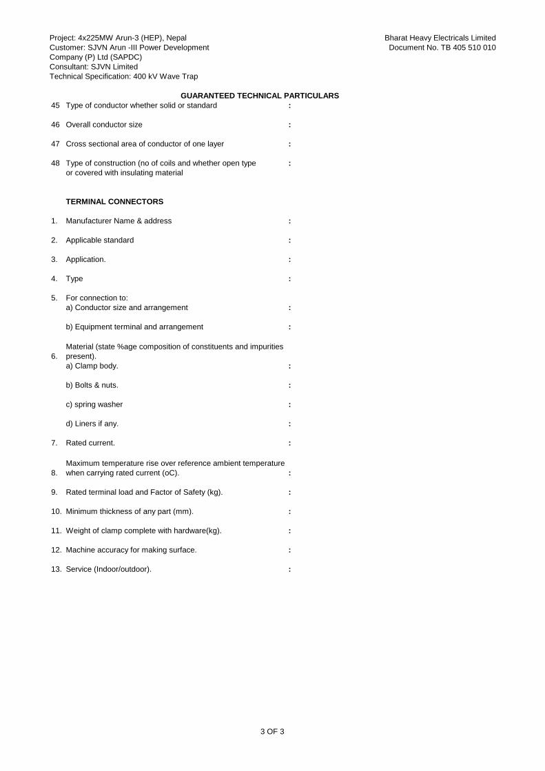
Project: 4x225MW Arun-3 (HEP), Nepal Customer: SJVN Arun -III Power Development Company (P) Ltd (SAPDC) Consultant: SJVN Limited Technical Specification: 400 kV Wave Trap
Bharat Heavy Electricals Limited Document No. TB 405 510 010
GUARANTEED TECHNICAL PARTICULARS45 Type of conductor whether solid or standard :
46 Overall conductor size :
47 Cross sectional area of conductor of one layer :
48 Type of construction (no of coils and whether open type :or covered with insulating material
TERMINAL CONNECTORS
1. Manufacturer Name & address :
2. Applicable standard :
3. Application. :
4. Type :
5. For connection to:a) Conductor size and arrangement :
b) Equipment terminal and arrangement :
6.a) Clamp body. :
b) Bolts & nuts. :
c) spring washer :
d) Liners if any. :
7. Rated current. :
8. :
9. Rated terminal load and Factor of Safety (kg). :
10. Minimum thickness of any part (mm). :
11. Weight of clamp complete with hardware(kg). :
12. Machine accuracy for making surface. :
13. Service (Indoor/outdoor). :
Maximum temperature rise over reference ambient temperature when carrying rated current (oC).
Material (state %age composition of constituents and impurities present).
3 OF 3
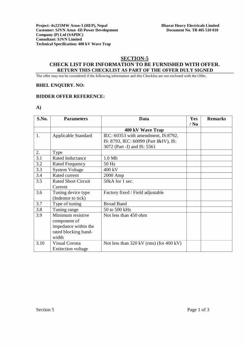
Project: 4x225MW Arun-3 (HEP), Nepal Bharat Heavy Electricals Limited Customer: SJVN Arun -III Power Development Document No. TB 405 510 010 Company (P) Ltd (SAPDC) Consultant: SJVN Limited Technical Specification: 400 kV Wave Trap
Section 5 Page 1 of 3
SECTION-5 CHECK LIST FOR INFORMATION TO BE FURNISHED WITH OFFER.
RETURN THIS CHECKLIST AS PART OF THE OFFER DULY SIGNED The offer may not be considered if the following information and this Checklist are not enclosed with the Offer. BHEL ENQUIRY. NO: BIDDER OFFER REFERENCE: A) S.No. Parameters Data Yes
/ No Remarks
400 kV Wave Trap 1. Applicable Standard IEC: 60353 with amendment, IS:8792,
IS: 8793, IEC: 60099 (Part I&IV), IS: 3072 (Part -I) and IS: 5561
2. Type 3.1 Rated Inductance 1.0 Mh 3.2 Rated Frequency 50 Hz 3.3 System Voltage 400 kV 3.4 Rated current 2000 Amp 3.5 Rated Short Circuit
Current 50kA for 1 sec.
3.6 Tuning device type (Indentor to tick)
Factory fixed / Field adjustable
3.7 Type of tuning Broad Band 3.8 Tuning range 50 to 500 kHz 3.9 Minimum resistive
component of impedance within the rated blocking band-width
Not less than 450 ohm
3.10 Visual Corona Extinction voltage
Not less than 320 kV (rms) (for 400 kV)
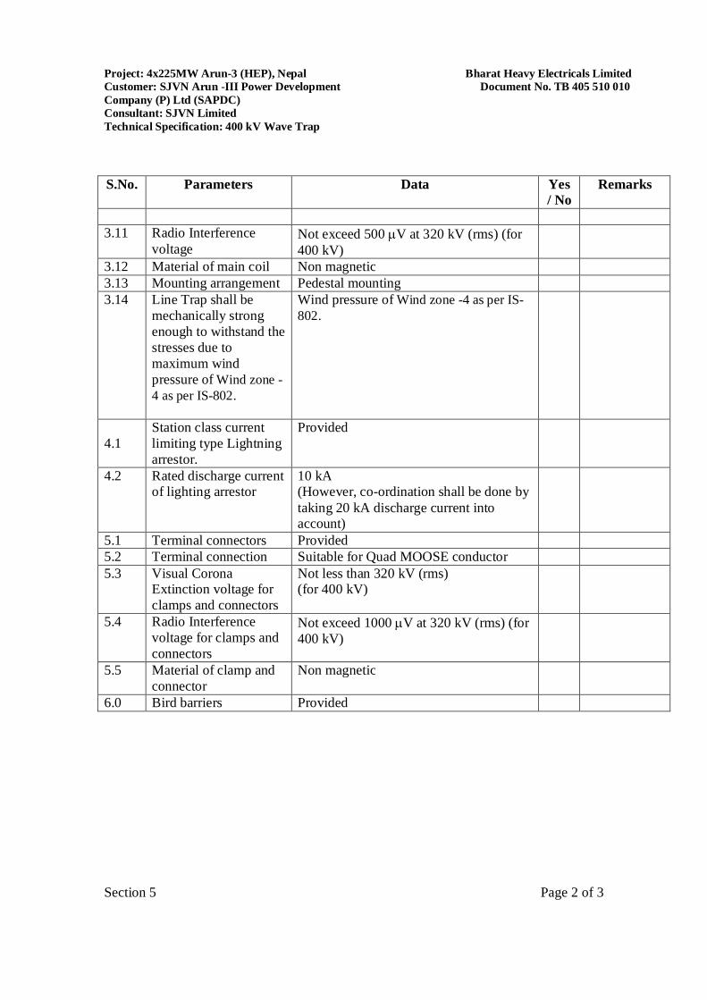
Project: 4x225MW Arun-3 (HEP), Nepal Bharat Heavy Electricals Limited Customer: SJVN Arun -III Power Development Document No. TB 405 510 010 Company (P) Ltd (SAPDC) Consultant: SJVN Limited Technical Specification: 400 kV Wave Trap
Section 5 Page 2 of 3
S.No. Parameters Data Yes
/ No Remarks
3.11 Radio Interference
voltage Not exceed 500 V at 320 kV (rms) (for 400 kV)
3.12 Material of main coil Non magnetic 3.13 Mounting arrangement Pedestal mounting 3.14 Line Trap shall be
mechanically strong enough to withstand the stresses due to maximum wind pressure of Wind zone -4 as per IS-802.
Wind pressure of Wind zone -4 as per IS-802.
4.1
Station class current limiting type Lightning arrestor.
Provided
4.2 Rated discharge current of lighting arrestor
10 kA (However, co-ordination shall be done by taking 20 kA discharge current into account)
5.1 Terminal connectors Provided 5.2 Terminal connection Suitable for Quad MOOSE conductor 5.3 Visual Corona
Extinction voltage for clamps and connectors
Not less than 320 kV (rms) (for 400 kV)
5.4 Radio Interference voltage for clamps and connectors
Not exceed 1000 V at 320 kV (rms) (for 400 kV)
5.5 Material of clamp and connector
Non magnetic
6.0 Bird barriers Provided
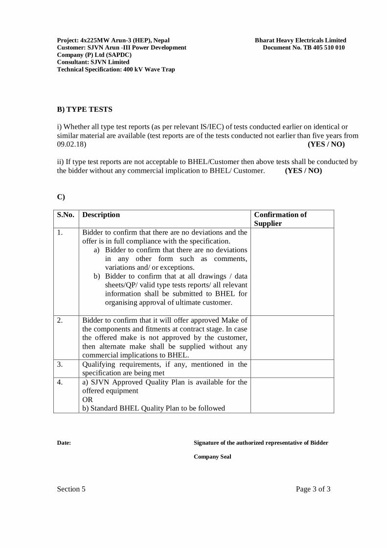
Project: 4x225MW Arun-3 (HEP), Nepal Bharat Heavy Electricals Limited Customer: SJVN Arun -III Power Development Document No. TB 405 510 010 Company (P) Ltd (SAPDC) Consultant: SJVN Limited Technical Specification: 400 kV Wave Trap
Section 5 Page 3 of 3
B) TYPE TESTS i) Whether all type test reports (as per relevant IS/IEC) of tests conducted earlier on identical or similar material are available (test reports are of the tests conducted not earlier than five years from 09.02.18) (YES / NO) ii) If type test reports are not acceptable to BHEL/Customer then above tests shall be conducted by the bidder without any commercial implication to BHEL/ Customer. (YES / NO) C) S.No. Description Confirmation of
Supplier 1. Bidder to confirm that there are no deviations and the
offer is in full compliance with the specification. a) Bidder to confirm that there are no deviations
in any other form such as comments, variations and/ or exceptions.
b) Bidder to confirm that at all drawings / data sheets/QP/ valid type tests reports/ all relevant information shall be submitted to BHEL for organising approval of ultimate customer.
2. Bidder to confirm that it will offer approved Make of the components and fitments at contract stage. In case the offered make is not approved by the customer, then alternate make shall be supplied without any commercial implications to BHEL.
3. Qualifying requirements, if any, mentioned in the specification are being met
4. a) SJVN Approved Quality Plan is available for the offered equipment OR b) Standard BHEL Quality Plan to be followed
Date: Signature of the authorized representative of Bidder
Company Seal

Bharat Heavy Electricals Limited 4x225MW Arun-3 (HEP),Nepal Technical Specification for 336kV Surge Arrester
Doc No. TB-405-316-003
____________________________________________________________________________________________ Section 4: Annexure - A Page 1 of 1
ANNEXURE - A
SCHEDULE OF TECHNICAL DEVIATIONS
Bidder shall list out all technical potential deviation/ change request (s) along with clause with respect to technical specifications.
Sl. No. Page No. Clause No. Deviation Reason / Justification
Any deviation not specifically brought out in this section shall not be admissible for any commercial implication at later stage. Except to the technical deviations listed in this schedule, bidder’s offer shall be considered in full compliance to the tender specifications irrespective of any such deviation indicated / taken elsewhere in the submitted offer.
Date: Bidder’s Stamp & Signature
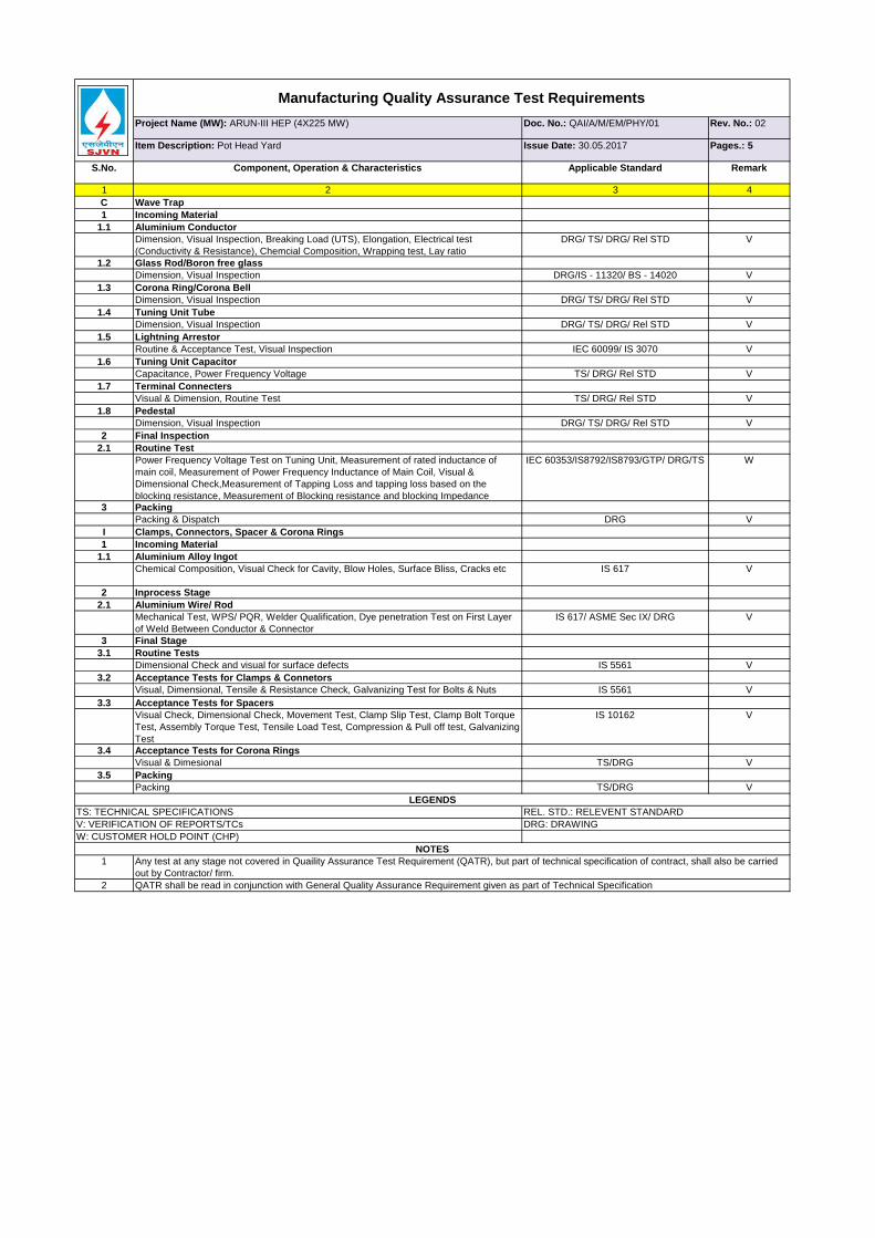
Project Name (MW): ARUN-III HEP (4X225 MW) Doc. No.: QAI/A/M/EM/PHY/01 Rev. No.: 02
Item Description: Pot Head Yard Issue Date: 30.05.2017 Pages.: 5
S.No. Component, Operation & Characteristics Applicable Standard Remark
1 2 3 4C Wave Trap1 Incoming Material
1.1 Aluminium ConductorDimension, Visual Inspection, Breaking Load (UTS), Elongation, Electrical test (Conductivity & Resistance), Chemcial Composition, Wrapping test, Lay ratio
DRG/ TS/ DRG/ Rel STD V
1.2 Glass Rod/Boron free glassDimension, Visual Inspection DRG/IS - 11320/ BS - 14020 V
1.3 Corona Ring/Corona BellDimension, Visual Inspection DRG/ TS/ DRG/ Rel STD V
1.4 Tuning Unit TubeDimension, Visual Inspection DRG/ TS/ DRG/ Rel STD V
1.5 Lightning ArrestorRoutine & Acceptance Test, Visual Inspection IEC 60099/ IS 3070 V
1.6 Tuning Unit CapacitorCapacitance, Power Frequency Voltage TS/ DRG/ Rel STD V
1.7 Terminal ConnectersVisual & Dimension, Routine Test TS/ DRG/ Rel STD V
1.8 PedestalDimension, Visual Inspection DRG/ TS/ DRG/ Rel STD V
2 Final Inspection2.1 Routine Test
Power Frequency Voltage Test on Tuning Unit, Measurement of rated inductance of main coil, Measurement of Power Frequency Inductance of Main Coil, Visual & Dimensional Check,Measurement of Tapping Loss and tapping loss based on the blocking resistance, Measurement of Blocking resistance and blocking Impedance
IEC 60353/IS8792/IS8793/GTP/ DRG/TS W
3 PackingPacking & Dispatch DRG V
I Clamps, Connectors, Spacer & Corona Rings1 Incoming Material
1.1 Aluminium Alloy IngotChemical Composition, Visual Check for Cavity, Blow Holes, Surface Bliss, Cracks etc IS 617 V
2 Inprocess Stage2.1 Aluminium Wire/ Rod
Mechanical Test, WPS/ PQR, Welder Qualification, Dye penetration Test on First Layer of Weld Between Conductor & Connector
IS 617/ ASME Sec IX/ DRG V
3 Final Stage3.1 Routine Tests
Dimensional Check and visual for surface defects IS 5561 V3.2 Acceptance Tests for Clamps & Connetors
Visual, Dimensional, Tensile & Resistance Check, Galvanizing Test for Bolts & Nuts IS 5561 V3.3 Acceptance Tests for Spacers
Visual Check, Dimensional Check, Movement Test, Clamp Slip Test, Clamp Bolt Torque Test, Assembly Torque Test, Tensile Load Test, Compression & Pull off test, Galvanizing Test
IS 10162 V
3.4 Acceptance Tests for Corona RingsVisual & Dimesional TS/DRG V
3.5 Packing Packing TS/DRG V
1
2
W: CUSTOMER HOLD POINT (CHP)NOTES
Any test at any stage not covered in Quaility Assurance Test Requirement (QATR), but part of technical specification of contract, shall also be carried out by Contractor/ firm.QATR shall be read in conjunction with General Quality Assurance Requirement given as part of Technical Specification
Manufacturing Quality Assurance Test Requirements
LEGENDSTS: TECHNICAL SPECIFICATIONS REL. STD.: RELEVENT STANDARDV: VERIFICATION OF REPORTS/TCs DRG: DRAWING
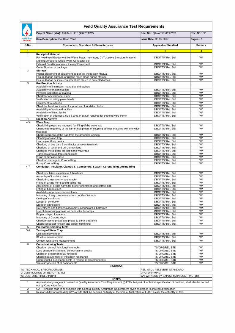
Project Name (MW): ARUN-III HEP (4X225 MW) Doc. No.: QAI/A/F/EM/PHY/01 Rev. No.: 02
Item Description: Pot Head Yard Issue Date: 30.05.2017 Pages.: 3
S.No. Component, Operation & Characteristics Applicable Standard Remark
1 2 3 4Receipt of MaterialPot head yard Equipment like Wave Traps, Insulators, CVT, Lattice Structure Material, Lighting Arrestors, Shield Wire, Conductor etc.
DRG/ TS/ Rel. Std. W*
External Condition of each & every Equipment DRG/ TS/ Rel. Std. W*Count Number of package DRG/ TS/ Rel. Std. W*StorageProper placement of equipment as per the Instruction Manual DRG/ TS/ Rel. Std. W*Ensure that no damage or rusting takes place during storage DRG/ TS/ Rel. Std. W*Ensure that all delicate equipment are stored in protected areas DRG/ TS/ Rel. Std. W*Pre-Erection ActivityAvaliability of instruction manual and drawingsAvailability of material at site DRG/ TS/ Rel. Std. W*Physical inspection of material DRG/ TS/ Rel. Std. W*Check for any damage, if any DRG/ TS/ Rel. Std. W*Verification of rating plate details DRG/ TS/ Rel. Std. W*Equipment foundation DRG/ TS/ Rel. Std. W*Check for level, verticality of support and foundation bolts DRG/ TS/ Rel. Std. W*Availability of tools and tackles DRG/ TS/ Rel. Std. W*Availability of lifting facility DRG/ TS/ Rel. Std. W*Verification of thickness, size & area of gravel required for pothead yard bench DRG/ TS/ Rel. Std. W*
4 Erection ActivityWave TrapCheck lifting eyes are not used for lifting of the wave trap DRG/ TS/ Rel. Std. W*Check that frequency of the carrier equipment of coupling devices matches with the wave trap band
DRG/ TS/ Rel. Std. W*
Check clearance of the trap from the grounded objects DRG/ TS/ Rel. Std. W*Cleaning of wave trap DRG/ TS/ Rel. Std. W*Use proper lifting device DRG/ TS/ Rel. Std. W*Checking of bus bars & contimuity between terminals DRG/ TS/ Rel. Std. W*Checking of tuner and LA Connections DRG/ TS/ Rel. Std. W*Check no metal parts are left in the wave trap DRG/ TS/ Rel. Std. W*Tightness of wave trap connections DRG/ TS/ Rel. Std. W*Fixing of birdcage mesh DRG/ TS/ Rel. Std. W*Check no damage in Corona Ring DRG/ TS/ Rel. Std. W*Fix up Corona Ring DRG/ TS/ Rel. Std. W*Conductor, Insulator, Clamps & Connectors, Spacer, Corona Ring, Arcing Ring
Check insulation cleanliness & hardware DRG/ TS/ Rel. Std. W*Assembly of insulator discs DRG/ TS/ Rel. Std. W*Check disc insulator for any cracks DRG/ TS/ Rel. Std. W*Fitting of arcing horns and grading ring DRG/ TS/ Rel. Std. W*Adjustment of arcing horns for proper orientation and correct gap DRG/ TS/ Rel. Std. W*Fitting of turn buckles DRG/ TS/ Rel. Std. W*Availability of proper crimping tools DRG/ TS/ Rel. Std. W*Mounting of sag compensator turn buckles/ tie rods DRG/ TS/ Rel. Std. W*Cutting of conductor DRG/ TS/ Rel. Std. W*Length of conductor DRG/ TS/ Rel. Std. W*Dropper connections DRG/ TS/ Rel. Std. W*Correctness and tightness of clamps/ connectors & hardware DRG/ TS/ Rel. Std. W*Use of deoxidizing grease on conductor & clamps DRG/ TS/ Rel. Std. W*Proper usage of spacers DRG/ TS/ Rel. Std. W*Mounting of Corona rings DRG/ TS/ Rel. Std. W*Check phase to phase and phase to earth clearance DRG/ TS/ Rel. Std. W*Check conductor tension and proper tightening DRG/ TS/ Rel. Std. W*
5 Pre-Commissioning TestsTesting of Wave TrapCoil continuity check DRG/ TS/ Rel. Std. W*IR value measurement DRG/ TS/ Rel. Std. W*Contact resistance measurement DRG/ TS/ Rel. Std. W*Commissioning TestsCheck on control functions/ interlocks TS/DRG/REL STD W*Loop check of instrument/ control/ alarm circuits TS/DRG/REL STD W*Check on protection relay functions TS/DRG/REL STD W*Check measurement of insulation resistance TS/DRG/REL STD W*Operational & Functional Tests in respect of all components TS/DRG/REL STD W*Visual inspection of all components TS/DRG/REL STD W*
1
23
Field Quality Assurance Test Requirements
1
2
3
5.4
4.5
4.7
Responsibitiy for witnessing (W*) at site shall be decided mutually at the time of finalization of FQAP as per the criticality of test.
6
LEGENDSTS: TECHNICAL SPECIFICATIONS REL. STD.: RELEVENT STANDARDV: VERIFICATION OF REPORTS/TCs DRG: DRAWINGW: CUSTOMER HOLD POINT W*: WITNESS BY SAPDC/ MAIN CONTRACTOR
NOTESAny test at any stage not covered in Quaility Assurance Test Requirement (QATR), but part of technical specification of contract, shall also be carried out by Contractor/ firm.QATR shall be read in conjunction with General Quality Assurance Requirement given as part of Technical Specification
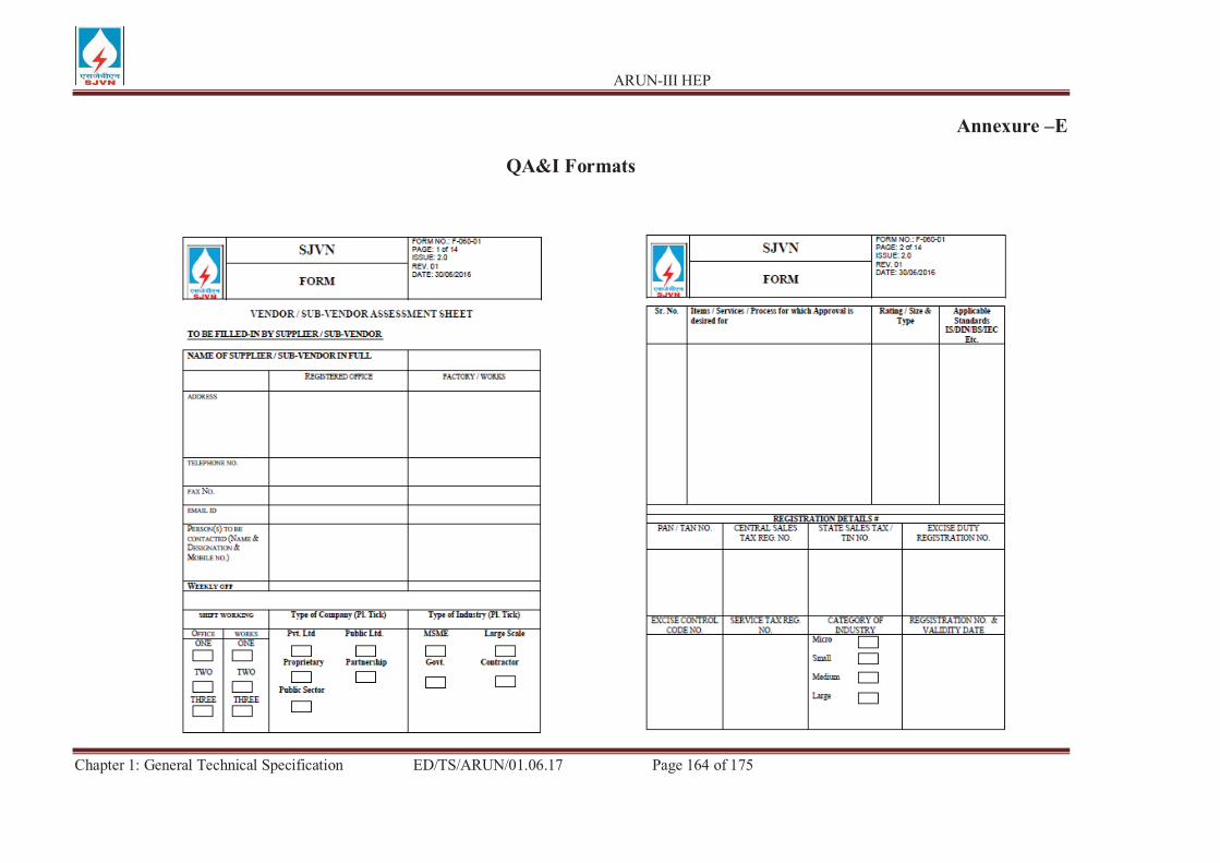
ARUN-III HEP
Chapter 1: General Technical Specification ED/TS/ARUN/01.06.17 Page 164 of 175
Annexure –E
QA&I Formats
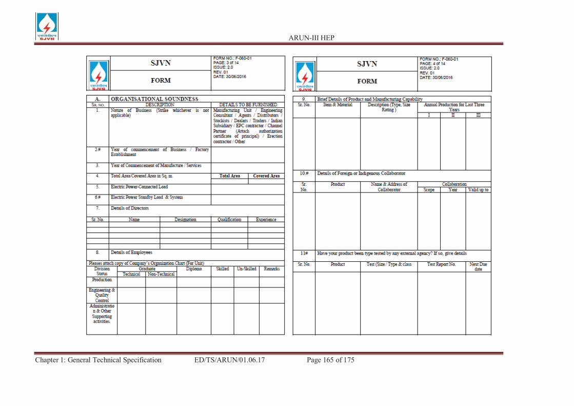
ARUN-III HEP
Chapter 1: General Technical Specification ED/TS/ARUN/01.06.17 Page 165 of 175
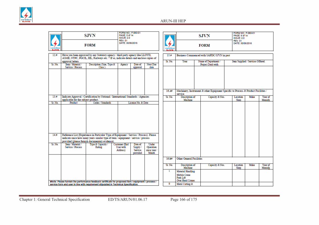
ARUN-III HEP
Chapter 1: General Technical Specification ED/TS/ARUN/01.06.17 Page 166 of 175
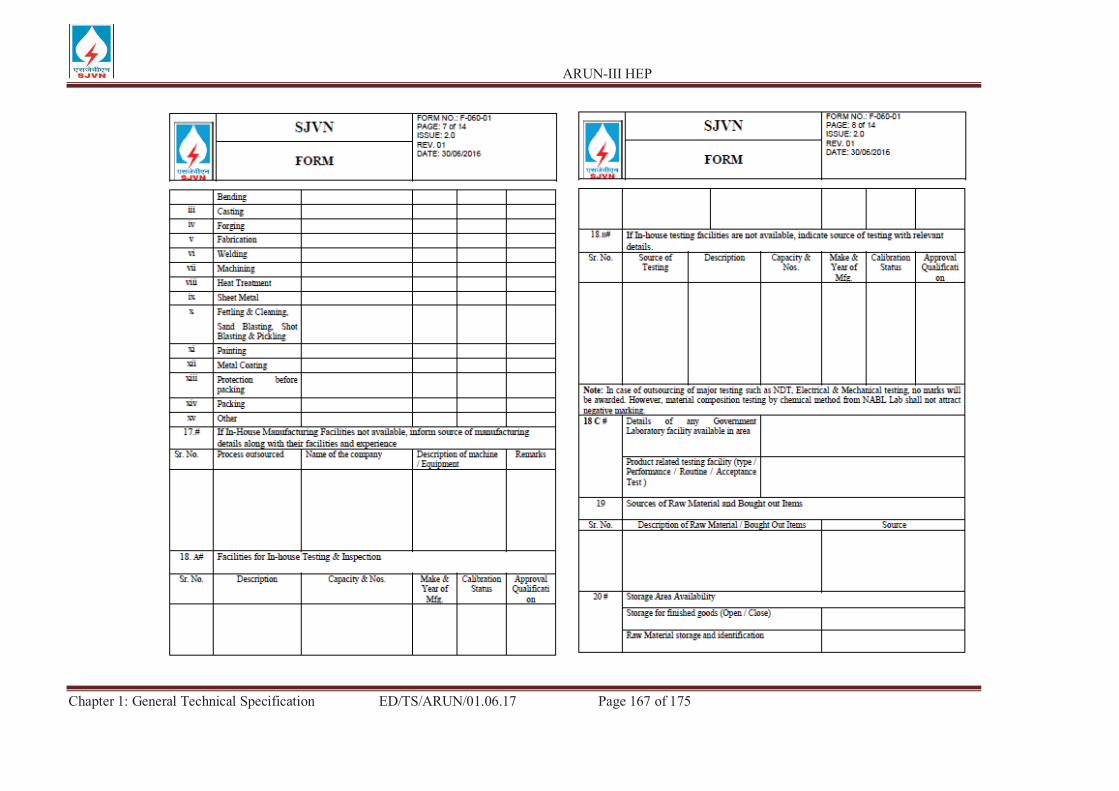
ARUN-III HEP
Chapter 1: General Technical Specification ED/TS/ARUN/01.06.17 Page 167 of 175
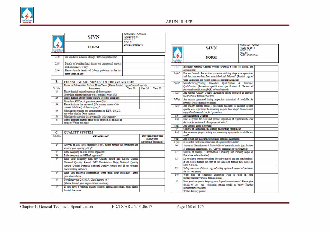
ARUN-III HEP
Chapter 1: General Technical Specification ED/TS/ARUN/01.06.17 Page 168 of 175
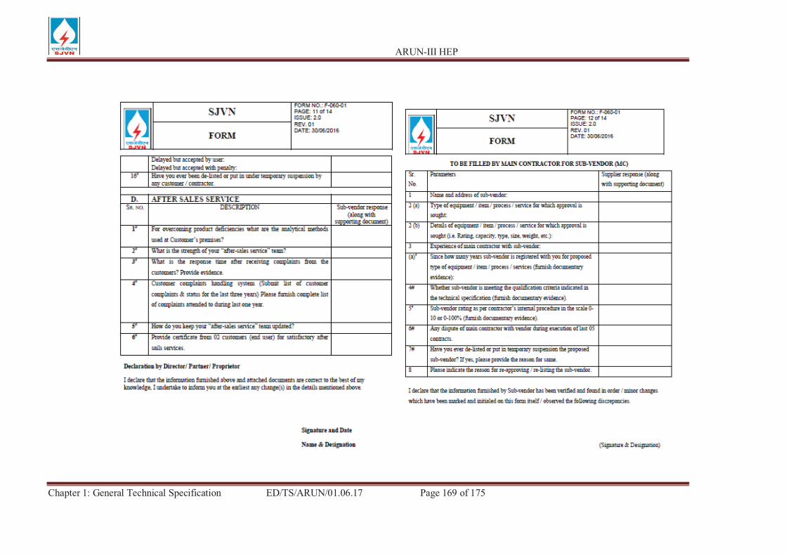
ARUN-III HEP
Chapter 1: General Technical Specification ED/TS/ARUN/01.06.17 Page 169 of 175
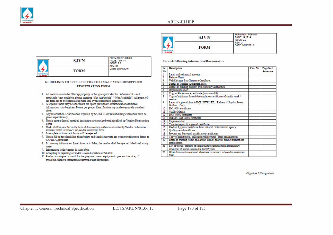
ARUN-III HEP
Chapter 1: General Technical Specification ED/TS/ARUN/01.06.17 Page 170 of 175

ARUN-III HEP
Chapter 1: General Technical Specification ED/TS/ARUN/01.06.17 Page 171 of 175
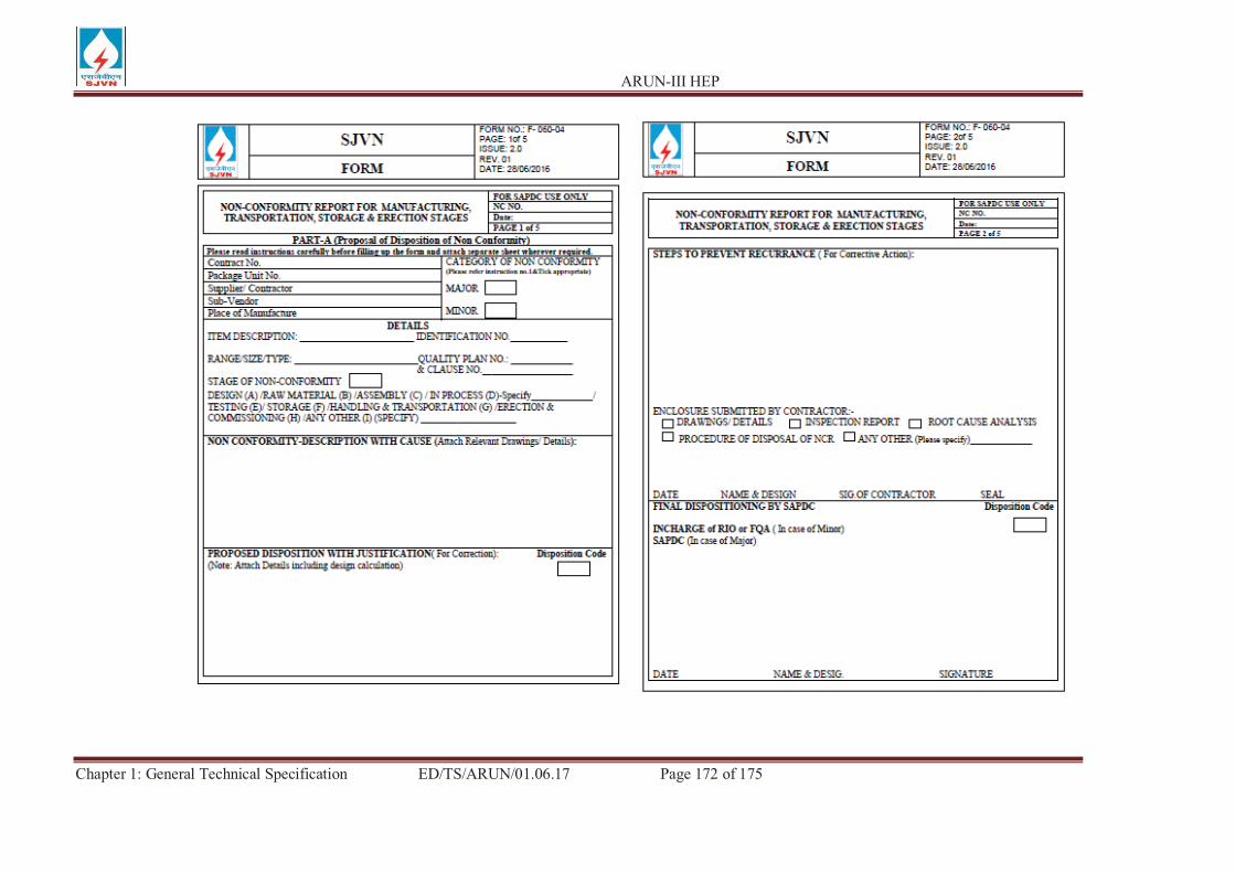
ARUN-III HEP
Chapter 1: General Technical Specification ED/TS/ARUN/01.06.17 Page 172 of 175
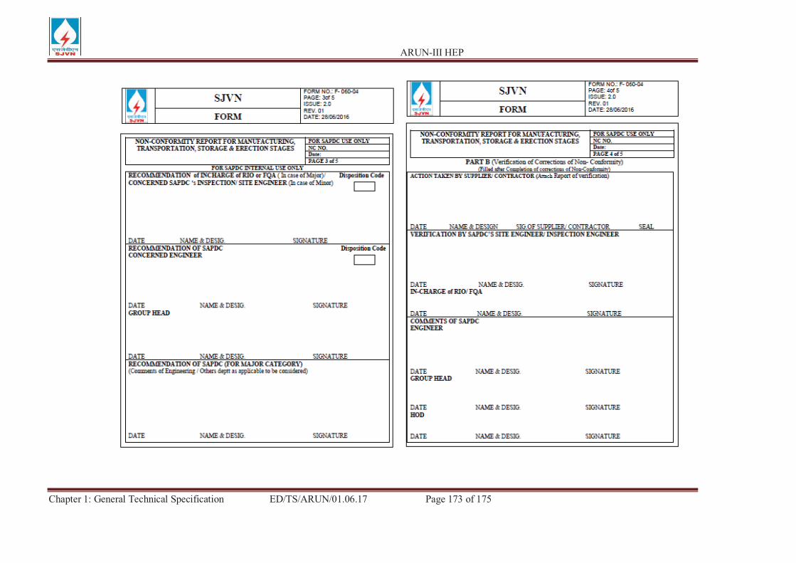
ARUN-III HEP
Chapter 1: General Technical Specification ED/TS/ARUN/01.06.17 Page 173 of 175

ARUN-III HEP
Chapter 1: General Technical Specification ED/TS/ARUN/01.06.17 Page 174 of 175
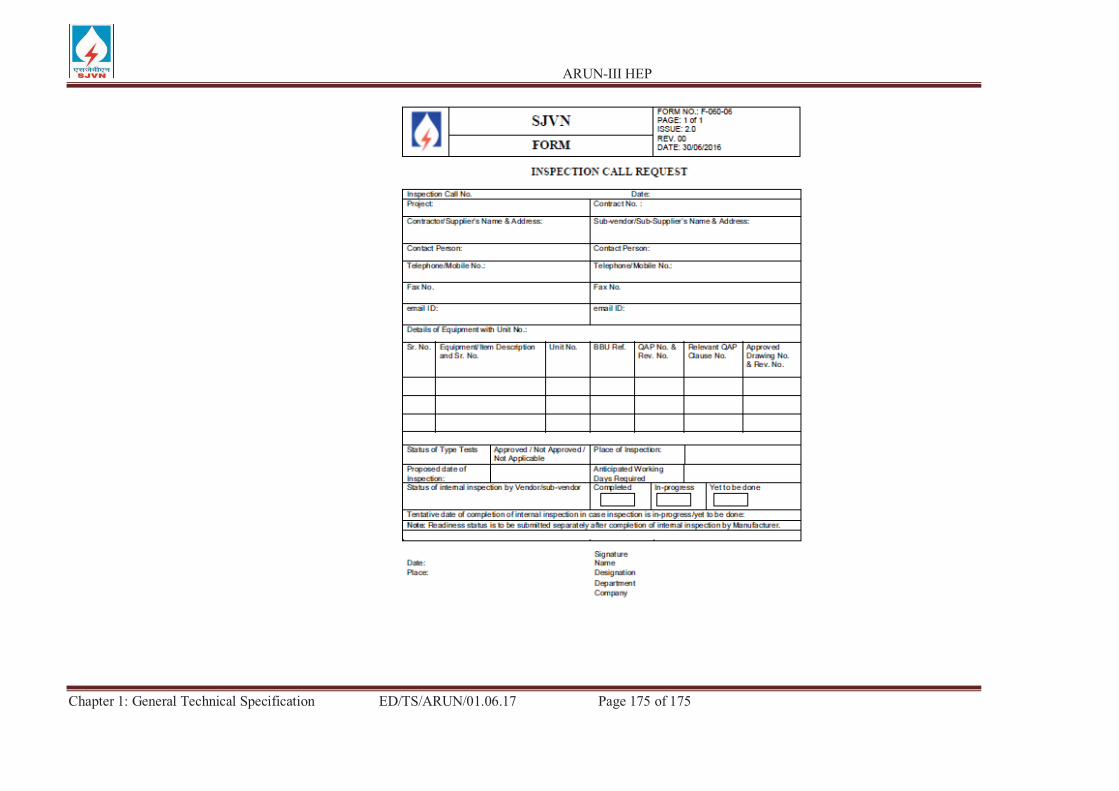
ARUN-III HEP
Chapter 1: General Technical Specification ED/TS/ARUN/01.06.17 Page 175 of 175

ANNEXURE-1 SEA WORTHY PACKING FOR EXPORT JOBS
1.0 SCOPE:
For export jobs, sea worthy packing capable of performing all necessary functions like prevention of damage to the contents, sufficient to support frequent handling and lengthy periods of outdoor storage in adverse weather conditions are required. Workmanship and material used shall meet the technical requirements and be in accordance with best commercial export packing practices. Vendor shall be responsible for the packing, however, it shall meet the minimum requirements specified herein. Equivalent or better packing methods may be deployed subject to approval of the purchaser. Vendor shall submit the packing procedure for its equipment for purchaser's approval during detailed engineering.
2.0 TECHNICAL SPECIFICATION OF WOOD:
The wood shall be Fir, Chir, Silver Oak (Grevillea Robusta) or chemically treated mango with moisture content not exceeding 50 %. The wood shall have flextural & compressive strength, stiffness, shock absorption and nail retention properties. The wood shall be free from common defects such as warp, bone, twist, knot, cracks, splits, end splits, bend, visible sign of infection and any kind of decay caused by insects, fungus etc. Surface cracks with a maximum depth of 3 mm are permissible. A continuous crack of any depth all along the length is not allowed.
The wood shall be chemically treated to provide protection against deterioration due to fungi and attack by termites, borers, marine organism and any other kind of infection. It shall be treated only after final processing like cutting, planing, joint grooving etc.
3.0 TYPE, DESIGN & DIMENSION OF WOODEN PACKING CASES:
3.1.1 PACKING OF EQUIPMENTS:
Various mechanical, electrical and C&I equipment e.g. pumps, motors, equipment skids, heat exchangers, control panels, switch gears, transformers etc. shall be wrapped in weather proof packing and then secured in wooden packing cases. The construction of wooden packing cases shall be as per details given below and also in figures 1 to 11.
3.1.1 BOTTOM FRAME:
The construction of bottom frame shall be as per fig. 2. The number of slides/runners for bottom frames shall be selected depending upon the weight and overall dimension of the load to be carried. The equipment shall be secured by fixing their base frame/plate with the help of bolt & nuts etc to the bottom frame of the wooden packing cases. The equipment not provided with the base frame/plate like
cylindrical vessels etc. to be secured to the bottom frame of the wooden case with ‘C’ clamps fabricated from steel channels/angle irons.
3.1.2 TOP FRAME:
The construction of top frame shall be as per fig. 3.
3.1.3 END PANELS:
The dimensions of the end and lateral panels shall be calculated according to overall dimensions of the items to be packed. Diagonal braces shall be used for packing cases having height exceeding 500 mm. Detail of bracing shall be as per figure 5 to 8.
3.1.4 SLING PLATE:
To facilitate lifting of cases, longitudnal under slide boards shall be fixed. To avoid damage to the box while lifting sling plates shall be provided. Refer fig. 11.
3.1.5 ANGLE IRON CLEATS :
Angle iron cleats shall be used for strengthening the joints as indicated in fig. 10.
3.1.6 OTHER REQUIREMENTS:
The thickness of planks for top, bottom, side and end panels shall be atleast 25 mm. Planks used for this purpose shall be joined with each other by tongue & groove joint. The groove dimension shall be such that tongue fits tightly into groove to make good joint.
Runners/slides, traverse bars etc. shall be of single length i.e. without any joint. Planks for sheathing, diagonal bracing etc shall also be of single length upto 2400 mm. For sizes larger than 2400 mm, proper jointing is permitted for planks for sheathing and diagonal bracing.
Each equipment to be individually covered with double polyethylene petticoat. Sheet thickness of polyethylene sheet shall not be less than 0.175 mm (175 microns). The sealing shall be such so as not to allow moisture inside. The inner surface of 4 sides of shooks shall be nailed with bituminised water proof kraft paper. Whereever 2 pieces of kraft paper are used, the joint shall have an overlap of minimum 20mm. All the inner sides of the box shall be nailed with bitumen coated hessian polyethylene kraft paper. For top frame it shall project on all sides by 100mm and shall be nailed on sides. Wherever 2 pieces of kraft paper are used, the joint shall have an overlap of minimum 20mm.
For delicate equipment like control panels, switchgears etc suitable cushioning material like rubberized coir shall be provided on their bottom support. The thickness of coir shall be 50 mm (minimum) and width 100 mm (minimum). For control panels and switchgears, the gap between the panel and casing shall be filled with rubberized coir with distance between consecutive supports less than 500 mm (ref fig 15). For other equipment suitable support from sides of the casing to be provided. Switchgear cubicles, control panels and control desks shall be packed and shipped in separate convenient sections. The components e.g. circuit breakers relays and instruments etc. which are removed from panels for shipping purpose shall be separately packed and shipped as per packing instructions in clause 3.2. Packing case for control panels & switchgear panels shall be finally covered with GI sheet of minimum thickness of 0.4 mm. Packing cases shall be bound at edges by nailing MS clamps/brackets at sufficient intervals. Further, heavier boxes shall be strapped with 'C' clamps (ref fig 4) fabricated from steel channels/angles and lighter boxes shall be strapped with hoop iron strips.
3.1.7 ALTERNATIVE PACKING CASES FOR CONTROL PANELS AND SWITCHGEARS
If required, for control and switchgear panels, construction of wooden packing cases may be provided as per fig 14 & 15 and as detailed below:
Thickness of planks for all sides, binding and jointing battens shall be atleast 25 mm. Width of planks shall be at least 125mm and that of binding and jointing planks shall be at least 100 mm.
Top frame shall be suitable so that it does not collapse due to sandwitching between slings while lifting. Longitudnal and traverse bars for the bottom wooden pallet to be suitably selected.
Diagonal bracings shall be as per clause 3.1.3 and All other requirements shall be as per clauses 3.1.4 to 3.1.6.
3.2 PACKING OF LOOSE ITEMS:
Loose mechanical, electrical and C&I items eg valves, fittings, pressure/temperature gauges/switches, circuit breakers, relays etc shall be individually wrapped using polyethylene sheets/U foam/thermocole sheets/air bubbled sheets depending upon the item and then packed in wooden boxes. The left out spaces and top of the boxes shall be filled with rubberized coir to get proper cushioning effect. Special attention is to be paid to relays, instruments etc for arresting the movement of their operating mechanisms during transportation.

The construction of wooden packing case shall be as per clause 3.1 retaining its all features concerning strength of box. The construction of wooden packing case for loose electrical and C&I items shall be as per fig. 16.
Inner surface of 6 sides of the box shall be lined with Bitumen coated hessian polyethylene kraft paper. Rubberized coir of min. 25 mm thickness and 100 mm width shall be nailed to inner surfaces of bottom and 4 sides of the box.
Loose items such as Galvanised Steel Structure, Cable support racks, Cable Trays and GI Pipes etc. shall be individually wrapped using polyethylene sheets and further lots may be wrapped in Bitumen coated hessian cloth.
4.0 MOISTURE ABSORBER:
Silica gel is used for this purpose to protect contents over sufficiently long time from corrosion. Silica gel shall be of indicating type conforming to IS-304-1979 packed in cotton bags placed at different positions inside the packing for absorbing moisture and shall not come directly into contact with the equipment / material inside the package. The quantity of silica gel shall be enough for storage period of one (1) year, however, it shall not be less than 4 gms per litre volume of case subject to minimum of 400 gms per case.
5.0 INDICATION MARKS ON THE BOXES:
Markings shall be provided on the boxes indicating position of boxes for handling, storage and nature of consignment. For guidelines refer figure 12. The ink used for this purpose as well as for marking despatch instruction shall be indelible/nonwashable marking ink.
6.0 DESPATCH DETAILS:
External front and rear sides of the boxes to be planed for writing instructions.
Dispatch details such as consignor/consignee address, contract and case details, country of origin , port of delivery, stacking instructions shall be written on one of the side of boxes. An anodised aluminium plate shall be provided on one side of the boxes.
One copy of packing slip wrapped in polyethylene bag covered with aluminium packing slip holder to be nailed on the external surface of the box. One more copy of the packing slip wrapped in polyethylene bag to be kept inside the box at the prominent place.
7.0 INSPECTION:
There shall be a Customer Hold Point (CHP) for inspection of final assembly of packing. During above inspection, the records for Chemical Treatment shall be reviewed.
- - x x - -
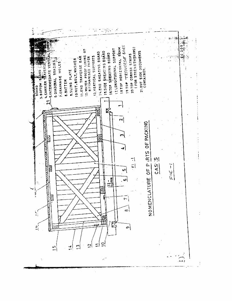
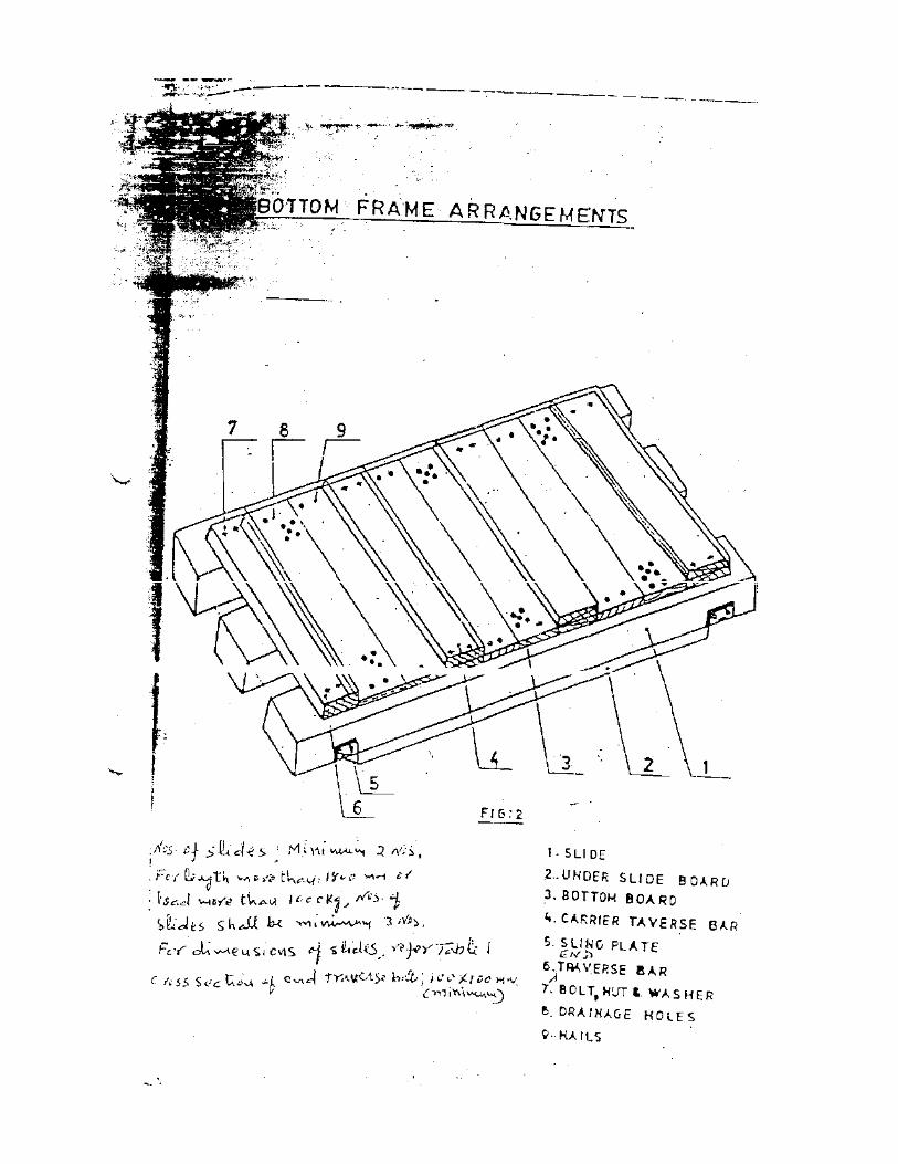


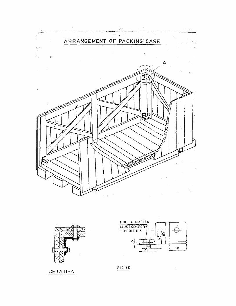
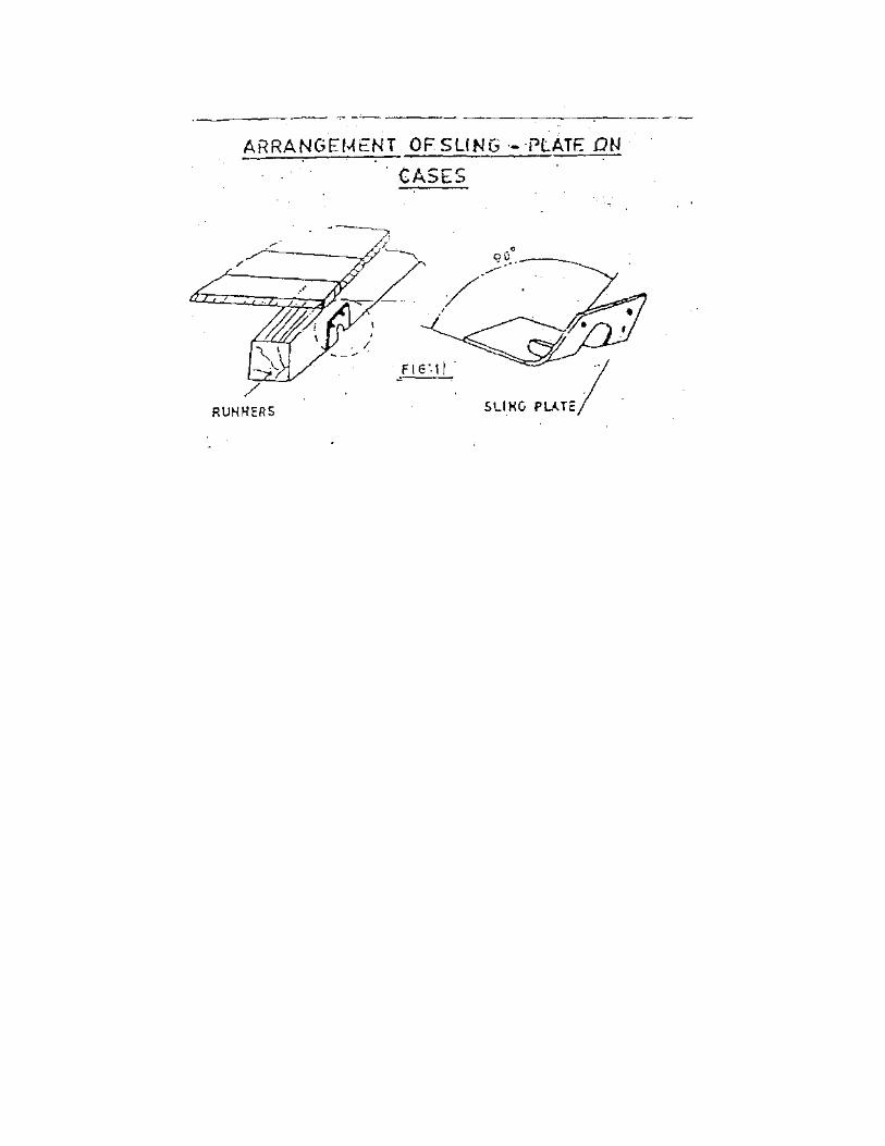
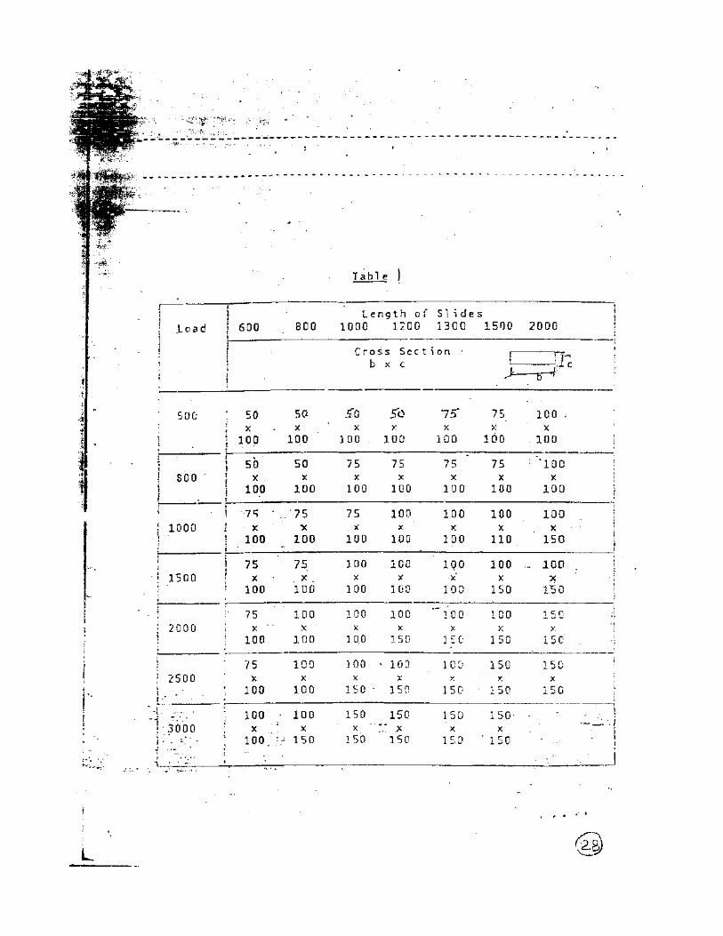
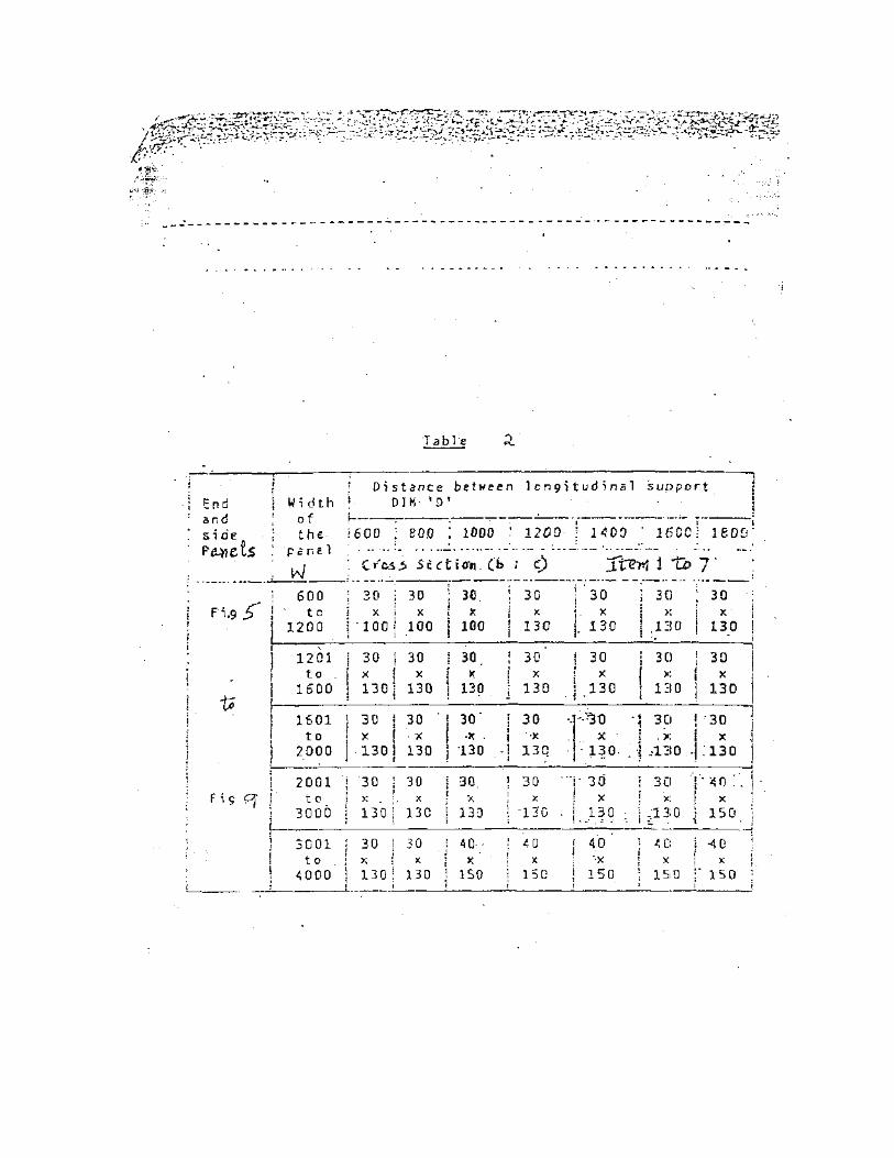
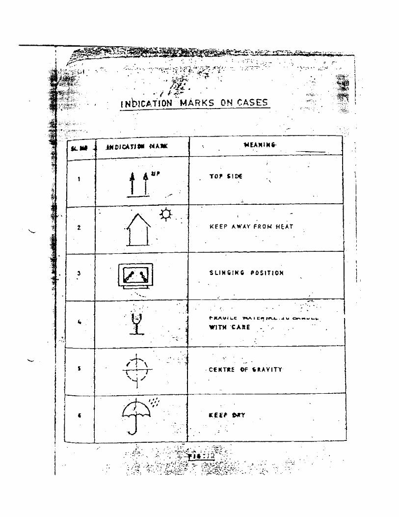
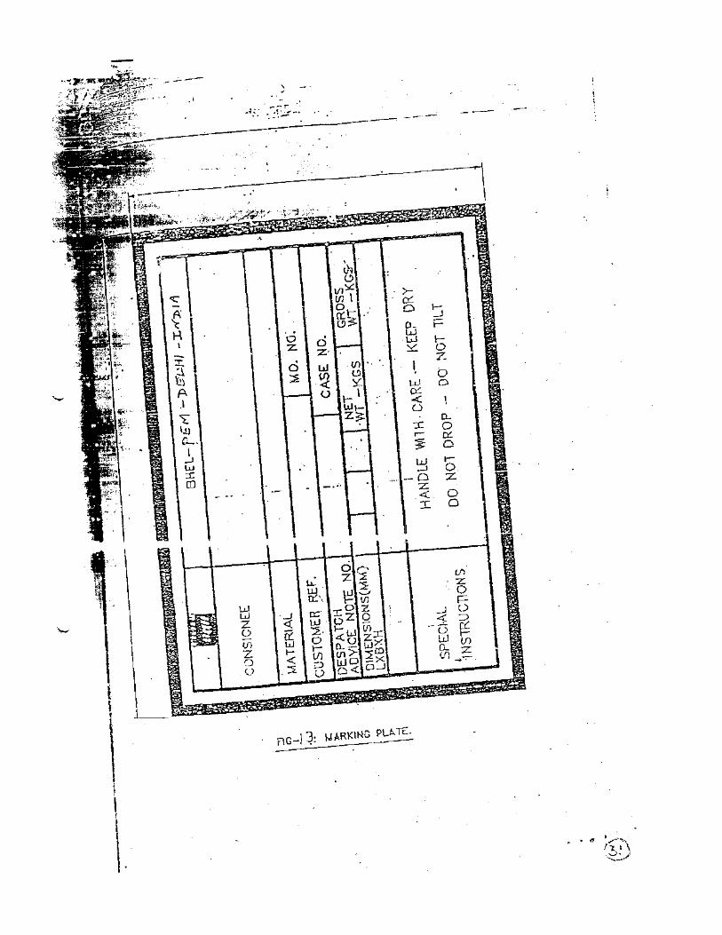
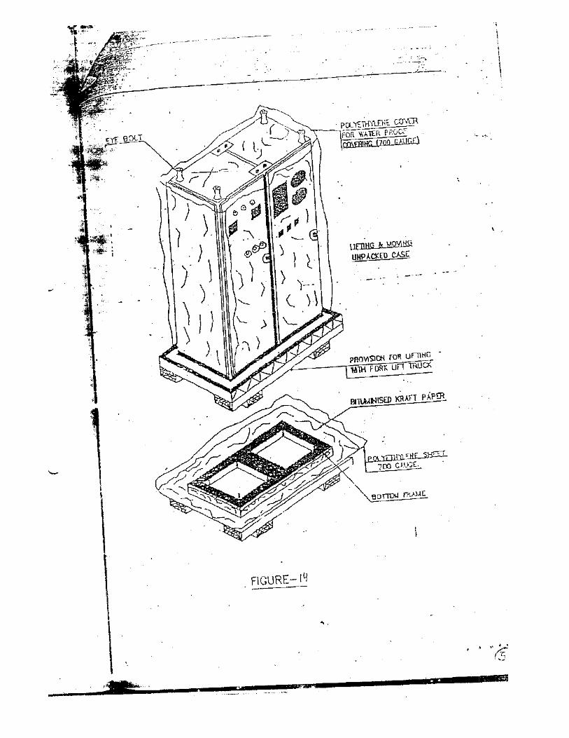
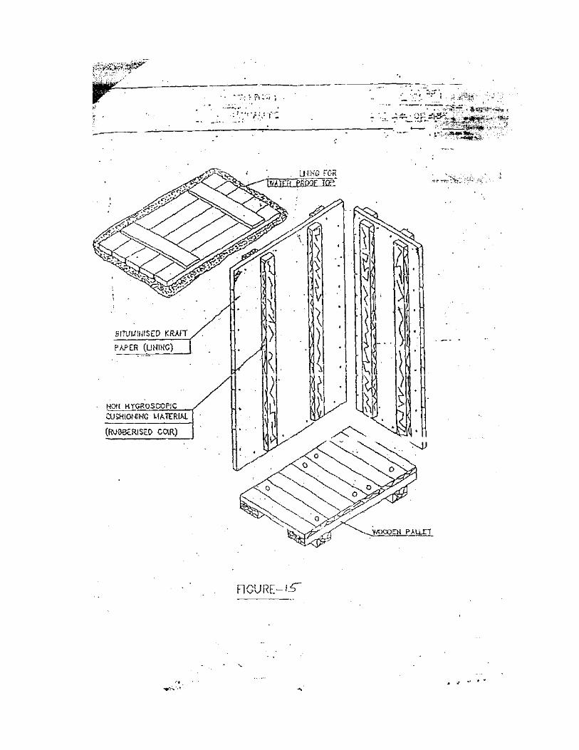
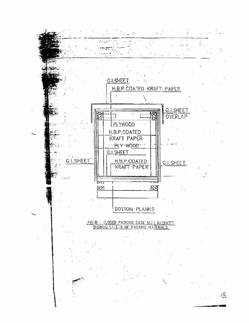


![arXiv:1808.01295v3 [hep-th] 29 Mar 2019 · 2019-04-01 · Finite temperature Schwinger pair production in coexistent electric and magnetic elds Mrunal Korwar1,2, and Arun M. Thalapillil1,](https://img.pdfslide.net/doc/110x75/5e68908c7b0bb81d9a434688/arxiv180801295v3-hep-th-29-mar-2019-2019-04-01-finite-temperature-schwinger.jpg)