Embed Size (px)
Citation preview
PA
GE
1M
AK
ER
BO
T E
DU
CA
TO
RS
GU
IDE
BO
OK
PR
OJE
CT
09
: AR
CH
IME
DE
S S
CR
EW
PROJECTNINE ARCHIMEDES SCREW
BONANZA
LINK: thingiverse.com/thing:1769714 for access to handouts, videos and other materials associated with this project.
PA
GE
2M
AK
ER
BO
T E
DU
CA
TO
RS
GU
IDE
BO
OK
PR
OJE
CT
09
: A
RC
HIM
ED
ES
SC
RE
W
LESSON SUMMARY
The Archimedes Screw is a device believed to be invented by
Archimedes, one of the world’s greatest scientists, in the 3rd
century B.C. It was most o en used to transport water from lower
ground to higher ground for irrigation, flood prevention, and more.
Interestingly, it is still used today in many di rent applications.
Well before power tools were created, people had to cleverly use common
materials to make their work more e cient. The Archimedes screw is
one example of this type of simple machine. A basic design consists
of a screw (helical spiral part), a tube (full or partial), and a crank. By
rotating the crank, you can move large quantities of material up an
incline much more e ciently than by simply carrying it. All Archimedes
screw designs have the same basic components, but can take many
shapes and sizes depending on the application. Check out some videos
in the Thingiverse Education ™ post ( thingiverse.com/thing:1769714 ).
In this project, students will create or modify an Archimedes screw to transport
material from lower ground to higher ground. The sample file included was
designed in Onshape. The students’ task is to observe the sample printed screw
design, and create a more e cient screw design that fits into the supplied case.
LEARNING OBJECTIVES
A er completing this project, students will be able to:
› Discuss the history of the Archimedes screw
› Apply engineering principles to design a simple machine
› Comprehend and apply the fundamentals of parametric 3D design
› Understand the impact of changing design parameters
NGSS STANDARDS
HS-PS3-3: Energy Design, build, and refine a device that works within given
constraints to convert one form of energy into another form of energy.
HS-ETS1-2: Engineering Design Design a solution to a complex
real-world problem by breaking it down into smaller, more
manageable problems that can be solved through engineering.
HS-ETS1-4: Engineering Design Use a computer simulation to
model the impact of proposed solutions to a complex real-world
problem with numerous criteria and constraints on interactions
within and between systems relevant to the problem.
AUTHOR MakerBot Learning
@makerbotlearning
SUBJECT Engineering
AUDIENCE Grade Levels 9–12
DIFFICULT Y Advanced
SKILLS NEEDED Some Onshape ®
so ware experience
DURATION 10—12 Class Periods
GROUPS 3–4 Groups
6–7 Students / Group
MATERIALS 2 Large Bowls
Superglue
Bag of Dried Beans
Dual Lock Tape
Ruler or Calipers
SOFTWARE Onshape (web app)
APPLICABLE
PRINTERS Works with all
MakerBot ® Replicator ®
3D printers
PRINT TIME Prep: 65 hrs
Lesson: 25—30 hrs / Group
FILAMENT USED 3–4 Large Spools
PROJECTINFO
nredom gnisu efil ot noitnevni tneicna na sgnirb stcejorp sihT“ technology. While the project is definitely an investment in printing time and filament, the students’ final products make this lesson well worth the e ort!”
– MakerBot Learning
PA
GE
3M
AK
ER
BO
T E
DU
CA
TO
RS
GU
IDE
BO
OK
PR
OJE
CT
09
: AR
CH
IME
DE
S S
CR
EW
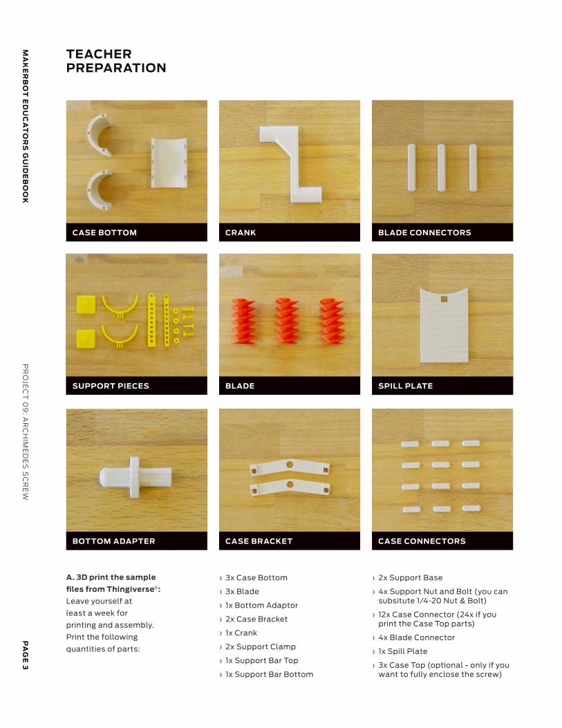
TEACHERPREPARATION
› 3x Case Bottom
› 3x Blade
› 1x Bottom Adaptor
› 2x Case Bracket
› 1x Crank
› 2x Support Clamp
› 1x Support Bar Top
› 1x Support Bar Bottom
A. 3D print the sample
files from Thingiverse :
Leave yourself at
least a week for
printing and assembly.
Print the following
quantities of parts:
› 2x Support Base
› 4x Support Nut and Bolt (you can subsitute 1/4-20 Nut & Bolt)
› 12x Case Connector (24x if you print the Case Top parts)
› 4x Blade Connector
› 1x Spill Plate
› 3x Case Top (optional - only if you want to fully enclose the screw)
SPILL PLATE
BLADE CONNECTORS
CASE CONNECTORSCASE BRACKET
BLADE
CRANK
BOTTOM ADAPTER
SUPPORT PIECES
CASE BOTTOM
®
PA
GE
4M
AK
ER
BO
T E
DU
CA
TO
RS
GU
IDE
BO
OK
PR
OJE
CT
09
: A
RC
HIM
ED
ES
SC
RE
W
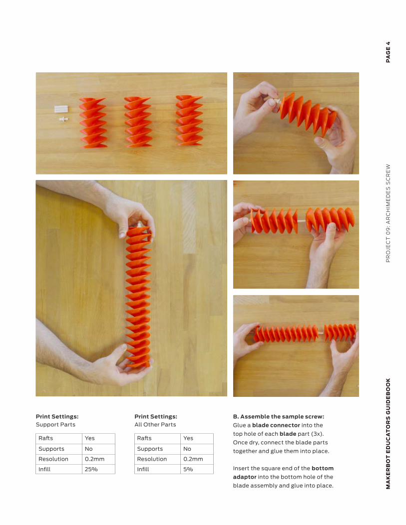
Ra s Yes
Supports No
Resolution 0.2mm
Infill 25%
Ra s Yes
Supports No
Resolution 0.2mm
Infill 5%
Print Settings: Support Parts
Print Settings: All Other Parts
B. Assemble the sample screw:
Glue a blade connector into the
top hole of each blade part (3x).
Once dry, connect the blade parts
together and glue them into place.
Insert the square end of the bottom
adaptor into the bottom hole of the
blade assembly and glue into place.
MA
KE
RB
OT
ED
UC
AT
OR
S G
UID
EB
OO
KP
RO
JEC
T 0
9: A
RC
HIM
ED
ES
SC
RE
WP
AG
E 5
MA
KE
RB
OT
ED
UC
AT
OR
S G
UID
EB
OO
K
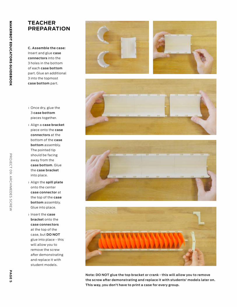
TEACHERPREPARATION
Note: DO NOT glue the top bracket or crank - this will allow you to remove
the screw after demonstrating and replace it with students’ models later on.
This way, you don’t have to print a case for every group.
C. Assemble the case:
Insert and glue case
connectors into the
3 holes in the bottom
of each case bottom
part. Glue an additional
3 into the topmost
case bottom part.
› Once dry, glue the
3 case bottom
pieces together.
› Align a case bracket
piece onto the case
connectors at the
bottom of the case
bottom assembly.
The pointed tip
should be facing
away from the
case bottom. Glue
the case bracket
into place.
› Align the spill plate
onto the center
case connector at
the top of the case
bottom assembly.
Glue into place.
› Insert the case
bracket onto the
case connectors
at the top of the
case, but DO NOT
glue into place - this
will allow you to
remove the screw
after demonstrating
and replace it with
student models.
PA
GE
6M
AK
ER
BO
T E
DU
CA
TO
RS
GU
IDE
BO
OK
PR
OJE
CT
09
: A
RC
HIM
ED
ES
SC
RE
W
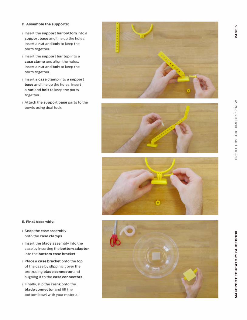
D. Assemble the supports:
› Insert the support bar bottom into a
support base and line up the holes.
Insert a nut and bolt to keep the
parts together.
› Insert the support bar top into a
case clamp and align the holes.
Insert a nut and bolt to keep the
parts together.
› Insert a case clamp into a support
base and line up the holes. Insert
a nut and bolt to keep the parts
together.
› Attach the support base parts to the
bowls using dual lock.
E. Final Assembly:
› Snap the case assembly
onto the case clamps.
› Insert the blade assembly into the
case by inserting the bottom adaptor
into the bottom case bracket.
› Place a case bracket onto the top
of the case by slipping it over the
protruding blade connector and
aligning it to the case connectors.
› FInally, slip the crank onto the
blade connector and fill the
bottom bowl with your material.
PA
GE
7M
AK
ER
BO
T E
DU
CA
TO
RS
GU
IDE
BO
OK
PR
OJE
CT
09
: AR
CH
IME
DE
S S
CR
EW
TEACHERPREPARATION
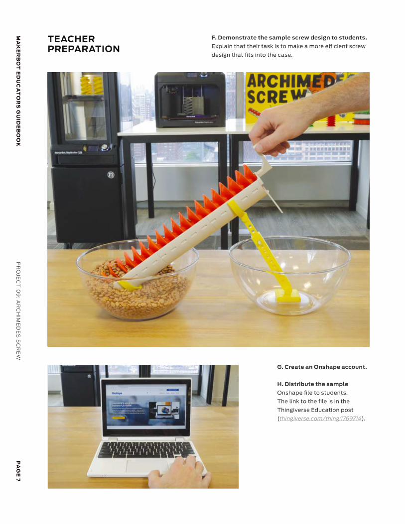
F. Demonstrate the sample screw design to students.
Explain that their task is to make a more efficient screw
design that fits into the case.
G. Create an Onshape account.
H. Distribute the sample
Onshape file to students.
The link to the file is in the
Thingiverse Education post
(thingiverse.com/thing:1769714).
PA
GE
8M
AK
ER
BO
T E
DU
CA
TO
RS
GU
IDE
BO
OK
PR
OJE
CT
09
: A
RC
HIM
ED
ES
SC
RE
W
STUDENTACTIVITY
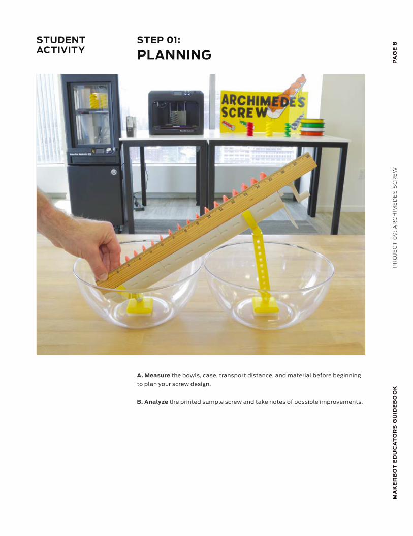
STEP 01:
PLANNING
A. Measure the bowls, case, transport distance, and material before beginning
to plan your screw design.
B. Analyze the printed sample screw and take notes of possible improvements.
PA
GE
9M
AK
ER
BO
T E
DU
CA
TO
RS
GU
IDE
BO
OK
PR
OJE
CT
09
: AR
CH
IME
DE
S S
CR
EW
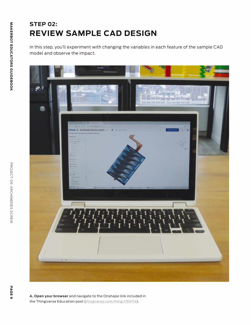
A. Open your browser and navigate to the Onshape link included in
the Thingiverse Education post (thingiverse.com/thing:1769714).
STEP 02:
REVIEW SAMPLE CAD DESIGN
In this step, you’ll experiment with changing the variables in each feature of the sample CAD model and observe the impact.
PA
GE
10
MA
KE
RB
OT
ED
UC
AT
OR
S G
UID
EB
OO
KP
RO
JEC
T 0
9:
AR
CH
IME
DE
S S
CR
EW
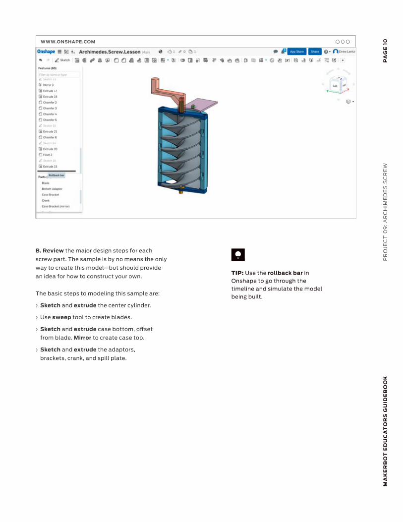
TIP: Use the rollback bar in Onshape to go through the timeline and simulate the model being built.
B. Review the major design steps for each
screw part. The sample is by no means the only
way to create this model—but should provide
an idea for how to construct your own.
The basic steps to modeling this sample are:
› Sketch and extrude the center cylinder.
› Use sweep tool to create blades.
› Sketch and extrude case bottom, offset
from blade. Mirror to create case top.
› Sketch and extrude the adaptors,
brackets, crank, and spill plate.
WWW.ONSHAPE.COM
PA
GE
11M
AK
ER
BO
T E
DU
CA
TO
RS
GU
IDE
BO
OK
PR
OJE
CT
09
: AR
CH
IME
DE
S S
CR
EW
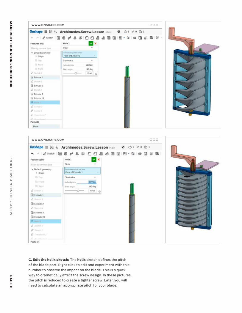
C. Edit the helix sketch: The helix sketch defines the pitch
of the blade part. Right click to edit and experiment with this
number to observe the impact on the blade. This is a quick
way to dramatically affect the screw design. In these pictures,
the pitch is reduced to create a tighter screw. Later, you will
need to calculate an appropriate pitch for your blade.
WWW.ONSHAPE.COM
WWW.ONSHAPE.COM
PA
GE
12
MA
KE
RB
OT
ED
UC
AT
OR
S G
UID
EB
OO
KP
RO
JEC
T 0
9:
AR
CH
IME
DE
S S
CR
EW
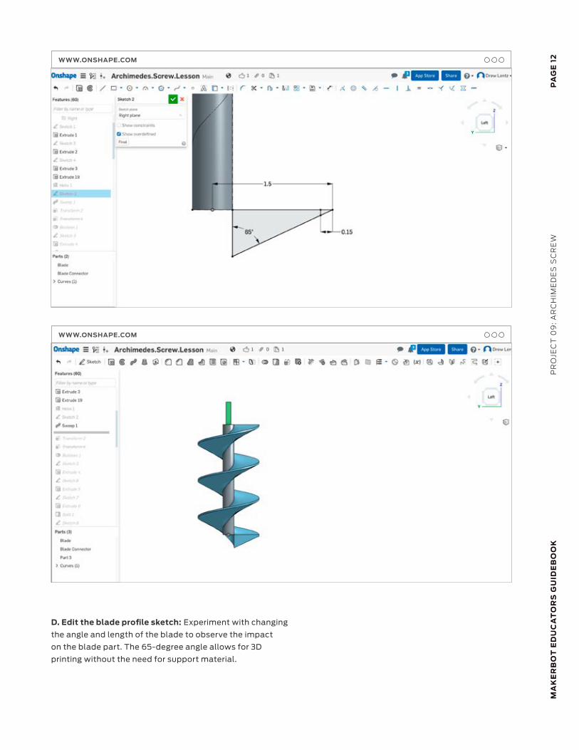
D. Edit the blade profile sketch: Experiment with changing
the angle and length of the blade to observe the impact
on the blade part. The 65-degree angle allows for 3D
printing without the need for support material.
WWW.ONSHAPE.COM
WWW.ONSHAPE.COM
PA
GE
13M
AK
ER
BO
T E
DU
CA
TO
RS
GU
IDE
BO
OK
PR
OJE
CT
09
: AR
CH
IME
DE
S S
CR
EW
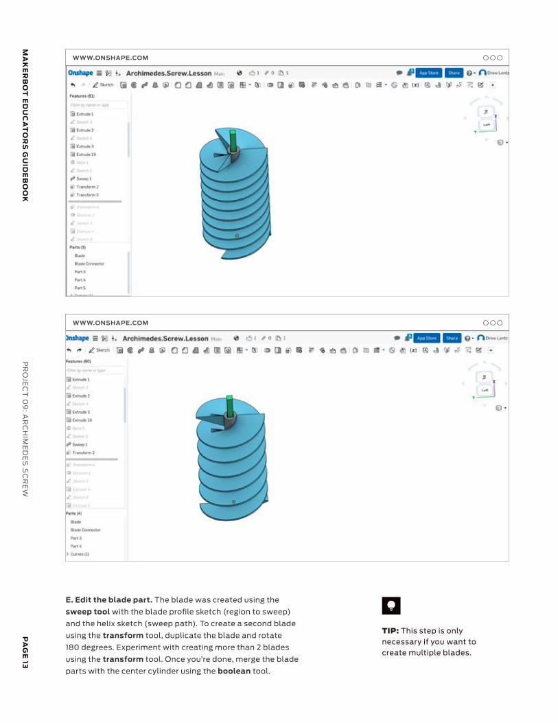
E. Edit the blade part. The blade was created using the
sweep tool with the blade profile sketch (region to sweep)
and the helix sketch (sweep path). To create a second blade
using the transform tool, duplicate the blade and rotate
180 degrees. Experiment with creating more than 2 blades
using the transform tool. Once you’re done, merge the blade
parts with the center cylinder using the boolean tool.
TIP: This step is only necessary if you want to create multiple blades.
WWW.ONSHAPE.COM
WWW.ONSHAPE.COM
PA
GE
14
MA
KE
RB
OT
ED
UC
AT
OR
S G
UID
EB
OO
KP
RO
JEC
T 0
9:
AR
CH
IME
DE
S S
CR
EW
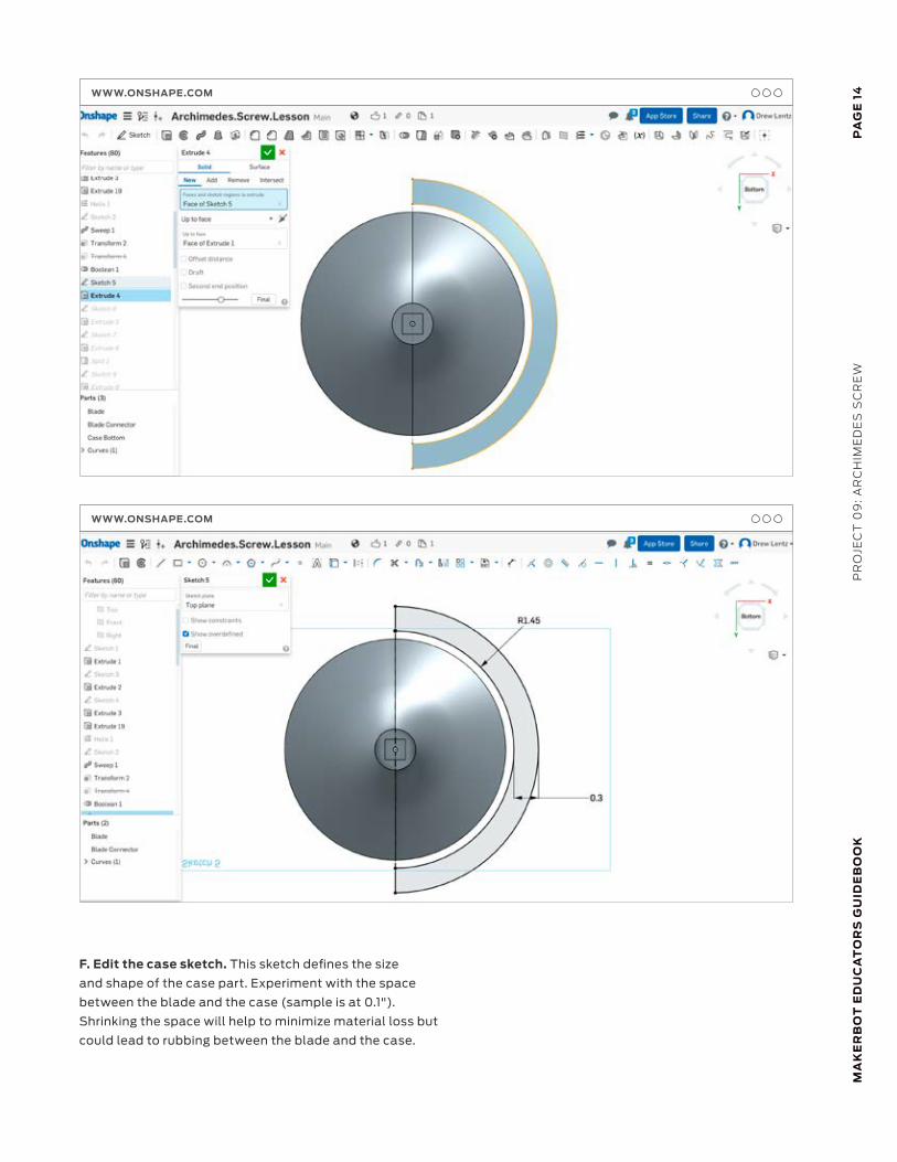
F. Edit the case sketch. This sketch defines the size
and shape of the case part. Experiment with the space
between the blade and the case (sample is at 0.1").
Shrinking the space will help to minimize material loss but
could lead to rubbing between the blade and the case.
WWW.ONSHAPE.COM
WWW.ONSHAPE.COM
PA
GE
15M
AK
ER
BO
T E
DU
CA
TO
RS
GU
IDE
BO
OK
PR
OJE
CT
09
: AR
CH
IME
DE
S S
CR
EW
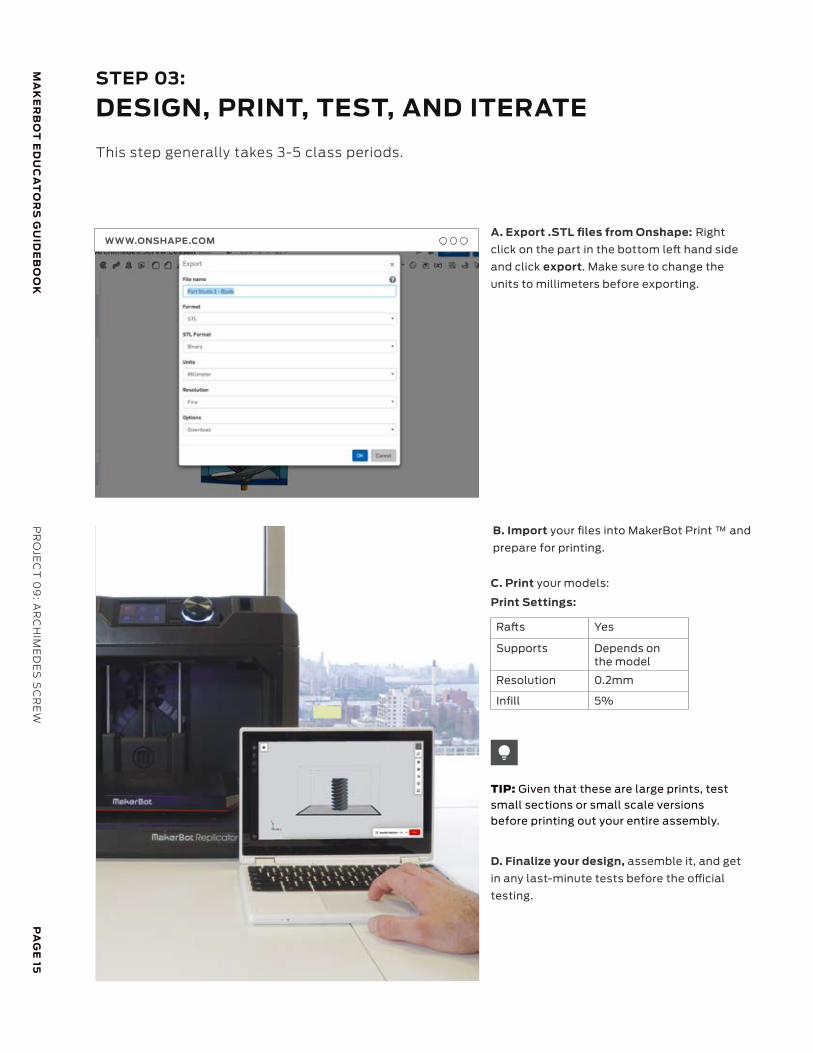
STEP 03:
DESIGN, PRINT, TEST, AND ITERATE
This step generally takes 3-5 class periods.
A. Export .STL files from Onshape: Right
click on the part in the bottom le hand side
and click export. Make sure to change the
units to millimeters before exporting.
B. Import your files into MakerBot Print ™ and
prepare for printing.
C. Print your models:
D. Finalize your design, assemble it, and get
in any last-minute tests before the o cial
testing.
Ra s Yes
Supports Depends on the model
Resolution 0.2mm
Infill 5%
Print Settings:
TIP: Given that these are large prints, test small sections or small scale versions before printing out your entire assembly.
WWW.ONSHAPE.COM
PA
GE
16
MA
KE
RB
OT
ED
UC
AT
OR
S G
UID
EB
OO
KP
RO
JEC
T 0
9:
AR
CH
IME
DE
S S
CR
EW
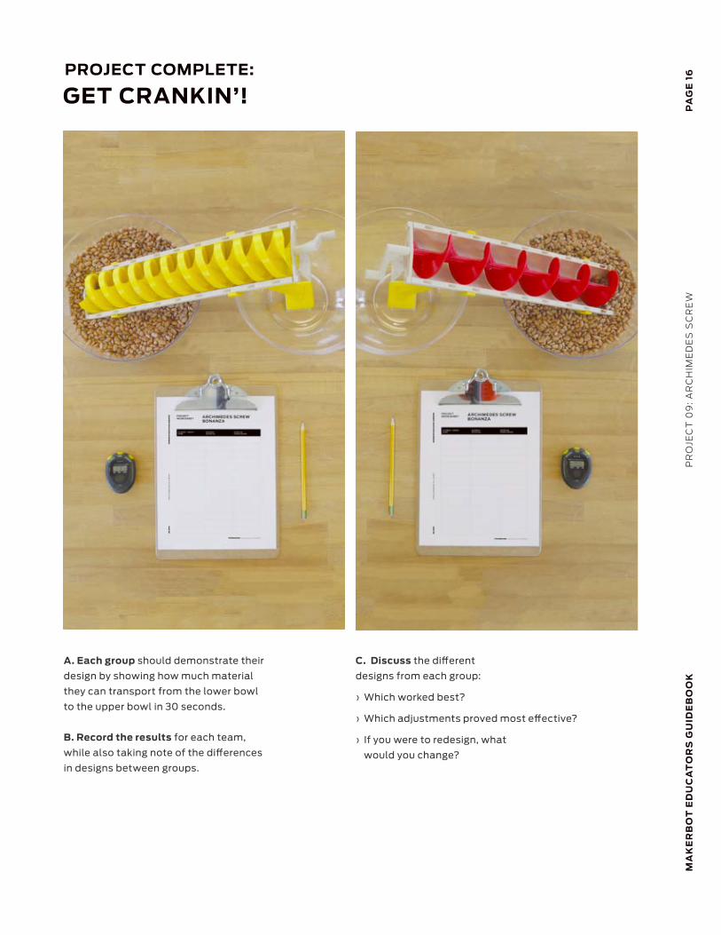
A. Each group should demonstrate their
design by showing how much material
they can transport from the lower bowl
to the upper bowl in 30 seconds.
B. Record the results for each team,
while also taking note of the differences
in designs between groups.
C. Discuss the different
designs from each group:
› Which worked best?
› Which adjustments proved most effective?
› If you were to redesign, what
would you change?
PROJECT COMPLETE:
GET CRANKIN’!
MA
KE
RB
OT
ED
UC
AT
OR
S G
UID
EB
OO
KP
RO
JEC
T 0
9: A
RC
HIM
ED
ES
SC
RE
WP
AG
E 17
MA
KE
RB
OT
ED
UC
AT
OR
S G
UID
EB
OO
K
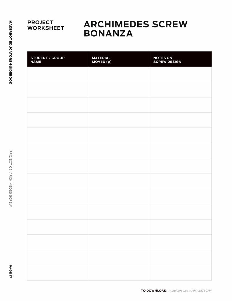
PROJECTWORKSHEET ARCHIMEDES SCREW
BONANZA
TO DOWNLOAD: thingiverse.com/thing:1769714
STUDENT / GROUP NAME
MATERIAL MOVED (g)
NOTES ON SCREW DESIGN
PA
GE
18
MA
KE
RB
OT
ED
UC
AT
OR
S G
UID
EB
OO
KP
RO
JEC
T 0
9:
AR
CH
IME
DE
S S
CR
EW
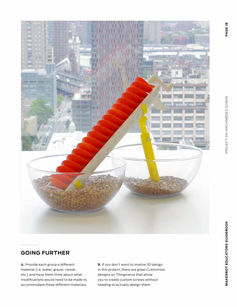
GOING FURTHER
A. Provide each group a different
material (i.e. water, gravel, cereal,
etc.) and have them think about what
modifications would need to be made to
accommodate these different materials.
B. If you don’t want to involve 3D design
in this project, there are great Customizer
designs on Thingiverse that allow
you to create custom screws without
needing to actually design them.

MA
KE
RB
OT
ED
UC
AT
OR
S G
UID
EB
OO
KL
EG
AL
LE
GA
L
TRADEMARKS
The MakerBot “M” logo, MakerBot, Replicator, Thingiverse, and Thingiverse Education are trademarks or registered trademarks of MakerBot Industries, LLC. All rights reserved.
Onshape is a registered trademark of Onshape Inc.
All other brand names, product names or trademarks belong to their respective holders. All rights reserved.
MakerBot Educators Guidebook, including Project 9, is an official product of MakerBot Industries, LLC, and is not authorized, sponsored, associated with, or otherwise associated with any of the other parties listed above in this Legal section or otherwise mentioned in the book.
All screenshots belong to their respective holders.
SCREENSHOTS
![Introductory Concepts - Wiley · 2020. 1. 14. · Source: Wikimedia [. org/wiki/File:Antikythera_mechanism_-_labelled.svg] Figure 1.1 Archimedes’ screw. Source: Wikimedia [ Brockhaus_and_Efron_Encyclopedic_Dictionary_b3_020-4.jpg]](https://img.pdfslide.net/doc/110x75/6139179ca4cdb41a985b7b9f/introductory-concepts-wiley-2020-1-14-source-wikimedia-orgwikifileantikytheramechanism-labelledsvg.jpg)

![Archimedes Powerpoint 8.12.2008.ppt [Kompatibilitätsmodus]haftendorn.uni-lueneburg.de/geschichte/griechen/Archimedes-berlips-nolte.pdf · Biographie IBiographie I • Archimedes](https://img.pdfslide.net/doc/110x75/5d66c48288c99356168b52cb/archimedes-powerpoint-8122008ppt-kompatibilitaetsmodus-biographie-ibiographie.jpg)


![Energy Saving in a Variable-Inclination Archimedes Screw · Energy Saving in a Variable-Inclination Archimedes Screw ... by Nagel [1] for the design of ... a screw pump according](https://img.pdfslide.net/doc/110x75/5af1e67f7f8b9a8b4c8f5a5a/energy-saving-in-a-variable-inclination-archimedes-screw-saving-in-a-variable-inclination.jpg)