Embed Size (px)
Citation preview
International Global Navigation Satellite Systems Society IGNSS Symposium 2013
Outrigger Gold Coast, Australia
16 – 18 July 2013
Project Biarri and the Namuru V3.2 Spaceborne GPS Receiver
Eamonn P. Glennon
Surveying & Geospatial Engineering, School of Civil & Environmental Engineering, UNSW, Australia
Joseph P. Gauthier School of Electrical Engineering & Telecommunications, UNSW, Australia
Mazher Choudhury Australian Centre for Space Engineering Research, UNSW, Australia
Kevin Parkinson General Dynamics Corporation, Albany, New Zealand
Andrew G. Dempster Australian Centre for Space Engineering Research,
School of Electrical Engineering & Telecommunications, UNSW, Australia [email protected]
ABSTRACT
The Namuru V3.2 GPS receiver is an Australian developed FPGA-based GPS receiver designed specifically for the Biarri Project; a multi-lateral Colony 2 cubesat defence project that Australia is participating in via the Defence Science and Technology Organisation. In this paper, a brief introduction to the Biarri mission requirements is provided, as are the various design features of the receiver that has been developed to satisfy those requirements. In particular, we focus on describing the features relating to operation of the receiver in low-earth orbit, in-orbit reprogramming of the receiver, and the provision of precise timing signals. GPS simulator test results using the latest generation of Namuru V3.2 receiver are also presented. These results show in-orbit positional accuracies within 10 m, velocity accuracies within 1 m/s and timing accuracies within 50 ns, while the warm-start time-to-first fix typically (90%) occurs within one minute.
KEYWORDS: Cubesat, Biarri, FPGA GPS receiver, Colony 2, Namuru.
1. INTRODUCTION
The University of New South Wales (UNSW) has been a leader in FPGA based GPS receivers for nearly a decade. This work commenced with the development of the Altera Namuru V1 and V2 receivers in 2004 by a team brought together within the former School of Surveying and Geospatial Engineering, which was recently merged into the School of Civil and Environmental Engineering, and continues to this day within the School of Electrical Engineering and Telecommunications and the Australian Centre for Space Engineering Research (ACSER). The formation of ACSER following the successful award of an Australian Space Research Program (ASRP) grant is notable for several reasons.
First, it has enabled the continued development of new generations of Altera FPGA based Namuru GNSS receivers, including the Namuru V31R1, the Namuru V33R6 and the Namuru V34R6. All of the Altera based GPS and GNSS receivers are highly flexible receiver designs that are intended primarily for research, with the receivers being manufactured and sold by General Dynamics Corporation (GDC) Ltd (New Zealand). GDC Ltd has been a collaborator with UNSW since the very beginning. Indeed, the Namuru V2 receivers have found extensive use throughout the world.
Second, it represents a watershed in the use of the Namuru receivers for real-world applications, with the design and development of a custom Namuru V3.2A receiver variant specifically for a high-profile highly complex Biarri cubesat mission for Defence Science and Technology Organisation (DSTO). For this work, UNSW engineers have been responsible for all hardware, firmware and FPGA designs, as well as being responsible for the verification and validation of the receiver as a whole.
This paper provides a brief heritage of Australian space based GPS receivers, describes the Biarri project and its inception, the requirements of that project and the UNSW solution designed to address those requirements. Some test results demonstrating the performance of the receiver are also included.
2. AUSTRALIAN AND NEW ZEALAND SPACE GPS RECEIVER HERITAGE
Although it is not widely known, Australia has a heritage in the supply of GPS receivers for the space industry. This started with the MG5001 GPS receiver that was manufactured by Canberra based SigNav Pty Ltd that was, until it went into voluntary administration and eventually sold to Swiss company uBlox, Australia's only manufacturer of GPS receiver technology. Although this situation came about more by accident than design, the fact of the matter was the MG5001 receiver firmware was easily replaceable by third parties and reference "GPS Architect" firmware and datasheets for the GPS chipset were readily available from the GPS chipset manufacturer. The effects of this were twofold. First, major space organisations such as DLR in Germany and SSTL in the UK purchased these receivers in reasonable quantities and replaced the firmware with their own custom firmware capable of satisfying the requirements for the satellite positioning needs using a low-cost commercial-off-the-shelf (COTS) receiver. DLR marketed the receiver as Phoenix (Montenbruck et al., 2006), while SSTL marketed it as SGR-05U (Ebinuma et al., 2004). Second, the successful use of these receivers in several major space missions demonstrated beyond doubt the feasibility of using a standard GPS receiver that did not include on its bill of materials components designed specifically for space.
The second example of Australian/New Zealand GPS receiver flight heritage is very similar to the SigNav MG5001 case, except here the receiver in question was the UNSW/General Dynamics Corporation Ltd Namuru V2R4 FPGA based GPS receiver. As was the case with the MG5001, the receiver firmware was replaced with alternate firmware after which it was successfully flown on a sounding rocket by DLR in Germany (Grillenberger & Markgraf, 2011).
Although both of these examples clearly demonstrate the capability of Australian and New Zealand companies to construct hardware capable of satisfying space requirements, the lack of a focused space industry, space agency or space research funding in Australia at the time meant that the work necessary to adapt the receivers for space requirements ended up being done overseas. This possibly resulted in a loss to the Australian economy and represents one example of why focussed government funding is essential if niche industries such as this are ever to be spawned in a country such as Australia.
3. AUSTRALIAN SPACE RESEARCH PROGRAM (ASRP) GRANTS
The Australian Space Research Program (ASRP) grants awarded in 2010 represent one of the responses of the Australian Government to the Senate Report "Lost in Space? Setting a new direction for Australia's space science and industry sector" (Economics, 2008). These grants have had a major effect on Australian space research, with one of the indirect consequences being a reboot of Australia's ability to enter the highly specialised GPS receiver market for very small satellites, commonly known as cubesats.
UNSW's ASRP project is titled 'SAR Formation Flying', with one of its key components being the design and implementation of a modernized GPS receiver capable of tracking Galileo E5 and E1 signals, as well as conventional GPS signals. The justification for this activity was that formation-flying satellites are known to require GNSS receivers capable of performing carrier phase processing in order to achieve centimetre accuracy, and most GNSS research being undertaken in universities around the world concerns the use of modernized signals such as Galileo. The outcome of this has been the development of three different Altera based GPS receivers, the Namuru V31R1, the Namuru V33R6 and the Namuru V34R6, as well as a concerted effort to port and adapt the UNSW Aquarius firmware to process Galileo signals using the new hardware and new radios. The construction of these GNSS receivers capable of processing new modernized signals represents an extremely challenging engineering activity, with a consequence that these receivers are unlikely to be suitable for an actual space mission, although they will be extremely useful in evaluation the technologies for future space missions. Nonetheless, the inclusion of this work-package did have the important effect of highlighting UNSW's GPS and GNSS capabilities to the Defence Science and Technology Organisation in Adelaide, who, as luck would have it, had the opportunity to participate in a multi-lateral space mission in conjunction with partners in the UK, Canada and the United States. This resulted in UNSW being invited to participate in what has subsequently been named the Biarri project.
4. PROJECT BIARRI
Project Biarri is a multi-lateral defence related project involving launch of three Boeing Colony II cubesats in a string of pearls formation (Newsam & Gordon, 2011). The US are providing the spacecraft, integration and launch, with Canada, the UK and Australia also contributing to the mission. The Australian contribution is the supply of GPS receiver
payloads for each of the spacecraft, with the GPS receivers required to satisfy the following requirements.
First, the GPS receivers are required to provide absolute GPS positioning to within ±10 m RMS. Second, the GPS receivers are required to provide relative positioning to within ±10 cm RMS, assuming that the separation of the spacecraft is no more than 10 km. Third, the receiver is required to provide timing accurate to ±20 ns. The receiver is also required to operate in orbit and under a wide temperature range, as well as having mechanical and electrical interfaces compatible with the Boeing Colony II bus (C2B).
Although the exact nature of the mission not known by authors, what is known is that the spacecraft will also be fitted with corner reflectors, thereby allowing the satellites to also be located using satellite laser ranging (SLR). This will allow useful experiments to be performed by Electro Optic Systems (EOS) Pty Ltd, an Australian based company that is a world leader in space situational awareness (SSA). As each Biarri spacecraft will be fitted with reaction wheels, small thrusters and solar panels, experiments to locate the spacecraft using SLR for different spacecraft orientations can be undertaken. These results can then be validated or aided using the GPS receiver payload.
When UNSW was first approached to assist with the provision of the GPS capability for this mission, two options were considered. The first and lowest risk option was to consider the purchase of a COTS original equipment manufacturer (OEM) receiver in which the ITAR speed and altitude limits had been removed. This approach was successfully employed for the CanX2 spacecraft, which used a Novatel OEM4 GPS receiver (Kahr, 2011). However, this approach comes with several significant disadvantages, including the fact that construction of an interfacing daughter board would have still been required and the receiver was not optimised or even designed for operation in low earth orbit (LEO). This would have also complicated the receiver concept of operations (CONOPS), as well as making it difficult to tailor the solution to the requirements. The second option was to redesign the Altera based Namuru V2R4/5 receiver in order to make it satisfy the requirements of the mission. Although this represented a significantly greater engineering risk, it came with the advantage of a commensurate increase in "developing capability", which is represents one of the aims of DSTO, as well as allowing a custom solution to be developed. It was also an option because all of the requirements are capable of being satisfied using a single frequency L1 C/A code receiver, although a dual frequency model does make differential carrier phase navigation easier. In addition, this solution also fitted neatly within the ACSER goals and a decision to pursue the second option was made.
5. NAMURU V3.2A RECEIVER
5.1 Hardware
The original Namuru V2R4/5 receiver, being UNSWs workhorse FPGA GPS receiver when UNSW was first approached on this matter, had several disadvantages that made it unsuitable for use in Biarri. These include the fact that the receiver was too large, it consumed far too much power, it used an SRAM based Altera FPGA making it susceptible to single event upsets (SEU) and single event latchups, and it contained two high power RF front-ends where only one was required. Furthermore, it did not have the required RS422 communications interface, it contained battery backed non-volatile memory that was not appropriate to space applications and it did not have the support for high accuracy and high precision timing, which was another of the requirements for the Biarri mission. Each of these points had to be
addressed for a replacement receiver to be acceptable.
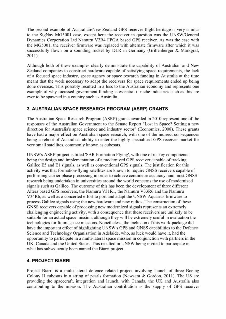
The Namuru V32AR3 GPS receiver (Glennon, Parkinson, et al., 2011) addresses each of these points and is designed satisfy other vital requirements. In order to eliminate the need for an interfacing daughter board, the printed circuit board (PCB) has been designed specifically to meet the electrical and mechanical requirements of the C2B. This amounts to a board with dimensions of 82 mm × 82 mm, mounting-holes with a particular size and location, specified interfacing and power connectors, as well as appropriate outer clearances, weight and centre-of-mass requirements. Changes were also made to the type of FPGAs employed by the receiver; with a switch from Altera SRAM based FPGAs to Actel MicroSemi flash based FPGAs. The design employs two Actel flash based FPGA devices, namely a ProASIC A3 FPGA with 38,400 Versatile logic tiles and a SmartFusion A2 FPGA containing a hard-wired ARM Cortex M3 processor and an additional 10,500 Versatile logic tiles. One board enhancement specifically included as a space related feature is the built-in latch-up detection circuitry, which is designed to detect excess current consumption and power cycle the board in such an event. The new design also replaces the battery-backed memory and battery powered real-time clock (RTC) with a serial flash non-volatile memory and an RTC powered by an ultra-capacitor. This avoids the need to include batteries on the board, which are understood to be problematic for space related devices. Finally, the hardware design includes specific features that allow for improved timing to be obtained from the receiver, with a voltage-controlled temperature compensated crystal oscillator (VC-TCXO) used instead of a standard TCXO. This allows the receiver to be employed for syntonization as well as synchronization applications (Glennon et al., 2013).
In order to avoid introducing too many changes from a system perspective, it was decided to retain the same Zarlink GP2015 RF front-end that was employed in the MG5001 and the Namuru V2R4/5 receivers. This was despite the fact that the part is no longer available for purchase from the manufacturer and that the part draws significantly more power than modern equivalents such as the Maxim 2769 RF front end. The advantage of this decision was that it allowed early algorithm and development work to be carried out using the Namuru V2R4 receiver, especially in relation to the generation and verification of the carrier phase measurements. It is possible that future versions of the design may employ different RF front-ends, but only after those devices have been proven using the Namuru V31R1, Namuru V33R6 and Namuru V34R6 receivers.
5.2 FPGA Designs
When the Namuru V32A receivers were in the design phase, a decision to employ Actel FPGAs in which the FPGA configuration was stored in Flash memory was made. One of the advantages this offers is that the configuration of the FPGA is immune to bit-flips caused by cosmic radiation. However, this benefit comes at a cost, which is that the logic tiles contained within the FPGA fabric used by the ProASIC A3 and SmartFusion A2 devices are not as capable as the FPGA logic elements found within the Altera Cyclone II devices. As such, while the 50,000 logic-element Cyclone II has more than sufficient capacity for 12 channels with 8 code phase taps per channel, plus a soft-core processor, this is certainly not possible for the ProASIC A3 device with its 38,400 logic tiles. Indeed, 38,400 logic tiles are barely sufficient for 12 channels with 3 code phase taps per correlator channel, which is the configuration currently programmed into the device. Unfortunately, the 11,520 logic-tiles of FPGA fabric contained within the SmartFusion A2 device is not sufficiently large for our current correlator design and this logic remains largely unused on these receivers.
5.3 Firmware
One of the difficulties associated with the switch from the Altera NIOS-2 soft-core processor to the hardwired ARM Cortex M3 processor was the need to convert the software from the Altera tool-chain to the ARM Keil tool-chain. Although this was mitigated by the fact that all of the GPS Aquarius firmware (Glennon, Mumford, et al., 2011) is written in ANSI C, certain processor dependent portions of the code required attention. This included the RTOS, as well as various low level device drivers needed to interface with the serial flash memory, the RTC and the UARTS used to perform serial port communications.
Other firmware changes were also required to cope with the specifics of operating the receiver in low earth orbit. First and foremost was the retuning of the satellite selection and acquisition code in order to allow acquisition of the satellites despite the increase in Doppler search space from ±4 kHz to ±40 kHz. However, that on its own still necessitated the need for long cold-starts each time the receiver was powered up. To overcome this obstacle, SGP4 orbit estimation code able to process NORAD two line elements (TLE) parameters describing the orbit of the spacecraft was also included thereby allowing for a warm start capability as well. Changes were also made to the navigation filter to include acceleration estimation terms based on the fact that a spacecraft in orbit has a very predictable acceleration that can be calculated from the position of the spacecraft.
5.4 Bootloader
Complex embedded systems such as mobile phones and GPS receivers typically have a significant portion of that complexity tied down in firmware running on an embedded microcontroller, with the Namuru V32A being no exception. Indeed, the Namuru V32A also has a user programmable FPGA that implements the signal correlators, making it even more complex than a typical embedded device.
Devices such as these will always contain bugs, and those bugs could be in any portion of the device that may be configured or programmed by the engineer. Although a thorough test regime can greatly assist in locating such bugs prior to deployment, there is always the risk that undetected bugs will hide within the product, only to be detected after the product is
Figure 1: Namuru V32AR3 GPS receiver board
operating in the field. As such, an ability to perform field upgrades on the firmware and FPGA designs is essential. This is even more important for devices placed in orbit, where there is absolutely no way to return the device to the factory for reprogramming.
In order to mitigate this state of affairs, the Namuru V32A was required to have an ability to reprogram both the firmware and FPGA designs while operating in the field. Our solution to this requirement was the inclusion of a custom bootloader that remains separate from the Aquarius operational firmware, with the bootloader required to satisfy the following requirements. First, the bootloader is required to permit the firmware in the Namuru V32A to be upgraded or downgraded as required. Second, it is also required to permit the A3 FPGA image to be upgraded, which is where the majority of the FPGA logic concerning the processing of GPS signals is located. Third, the communications protocol is required to be compatible with the same interfacing requirements imposed on the GPS serial communications, which in this case required the implementation of a bit-stuffing protocol whenever certain reserved characters were encountered, as well as ensuring each sentence complied with a maximum length constraint. Finally, some system level requirements of the receiver, such as being able to perform self-test functions on the receiver hardware have been incorporated into the bootloader, with this having the advantage of limiting the complexity of the Aquarius firmware while still being able to satisfy the system level requirements.
The SmartFusion A2 system-on-a-chip contains 512 kB of non-volatile Flash memory that may be used to store firmware images. Because the bootloader is required to be the first piece of code that runs when the processor is released from reset, the lowest 64 kB of this Flash memory is dedicated towards the bootloader functionality. Once the receivers have been deployed, this code will never be upgraded and therefore should never be accidentally corrupted should failed updates to the receiver take place. The Aquarius GPS firmware is less than 192 kB in size and as such, the bootloader allows two copies of Aquarius to be stored in the receiver flash memory, with serial port commands allowing one of the two images to be selected as the active image. Interaction with the bootloader takes place using serial port commands not unlike the NMEA commands used to interact with the firmware, although the NMEA checksum been replaced with a more robust 16-bit cyclic redundancy check (CRC). This is because the 8-bit exclusive-or checksum used by the NMEA protocol is not particularly reliable in the event of poor communications.
Upgrading the A3 FPGA represents one of the more complex operations performed by the bootloader. To satisfy this requirement, the 1.5 MB FPGA configuration file as generated by the Actel Libero tool-chain is transmitted to the receiver and stored in the 8 MB serial flash that is also used by Aquarius for storing almanac, ephemeris and other receiver configuration data. The bootloader then uses Actel supplied DirectC FPGA programming code to program the A3 FPGA using SmartFusion A2 GPIO pins that have been wired up to the ProASIC A3 JTAG pins. Because of this wiring setup, the only way to program the ProASIC A3 on production units is using the bootloader, although early development units also offered use of an underside JTAG connector that was enabled using appropriately loaded zero ohm resistors. It should be remarked that FPGA and firmware images are each accompanied by associated 32-bit CRCs and as such, any errors in the transmission of new firmware or new FPGA designs should have a very low risk of being undetected.
It should also be noted that the bootloader has gone through two revisions, with the initial version of the bootloader as described in (Mumford et al., 2012) having been revised in order to ensure compliance with the C2B serial port communications requirements. With this code restructure, changes were made to the locations in which the second Aquarius image is placed
and the mechanisms used to download the images. That said, many of the ideas and concepts of the first version were retained. Correct operation of the bootloader was validated during integration activities performed in March 2013 at the Air Force Research Laboratories (AFRL) in Albuquerque, New Mexico.
6. TEST RESULTS
The receiver and firmware have been subject to extensive testing at UNSW using the university's Spirent GPS simulators. Describing all of the tests that have been performed on the receiver is beyond the scope of a paper such as this, although further details on some of the tests performed may be found in (Choudhury et al., 2012) and (Glennon et al., 2013).
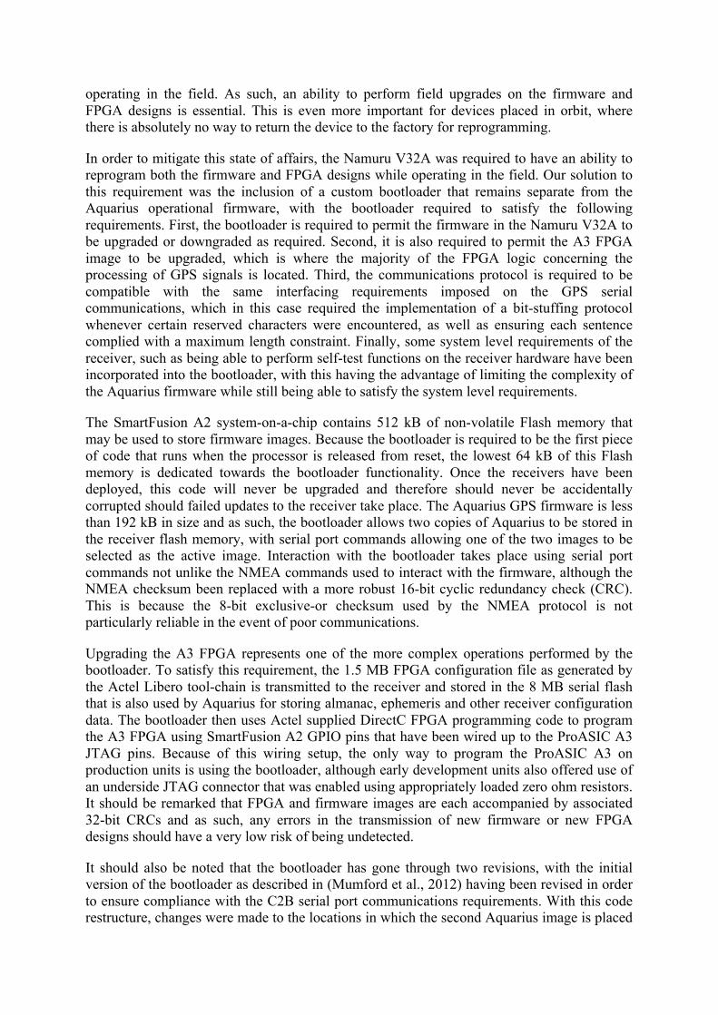
As an example of the receiver's current level of performance, the GPS simulator results obtained using a sun-synchronous orbit with an altitude of approximately 600 km are shown below in Figure 2. Here it can be seen that the position error is typically within 10 m, while the velocity errors are typically within 1 m/s, with further work required to reduce the velocity bias errors to lower levels. Random walk can be observed in the clock drift term due to the fact that for these tests, the VC-TCXO was not being controlled. This caused a linear drift in the clock bias, which is subject to a 'clock-reset' correction during the run in order to ensure that the time does not drift too far from the true time.
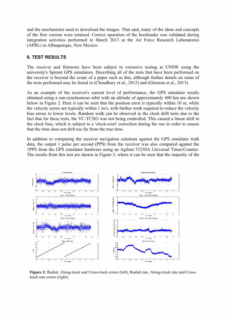
In addition to comparing the receiver navigation solutions against the GPS simulator truth data, the output 1 pulse per second (PPS) from the receiver was also compared against the 1PPS from the GPS simulator hardware using an Agilent 53230A Universal Timer/Counter. The results from this test are shown in Figure 3, where it can be seen that the majority of the
Figure 2: Radial, Along-track and Cross-track errors (left), Radial rate, Along-track rate and Cross-track rate errors (right).
timing errors are within ±12.5 ns. This derives directly from the use of a 40 MHz clock signal from the GP2015 radio frequency (RF) front-end as the main clock used to drive the GPS correlators and the timing circuits within the FPGA logic. The timing errors in this case typically lie within within the 25 ns clock cycle that lies closest to the true 1PPS, with this type of error typically referred to as a sawtooth error. The occasional excursion from this error band typically amounts to an error of a single clock cycle superimposed on this process, thereby resulting in a larger band of errors than would be expected were the errors only due to sawtooth effects.
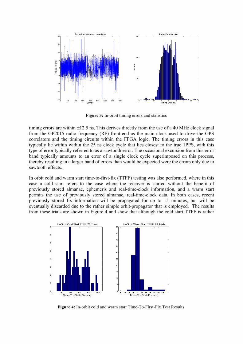
In orbit cold and warm start time-to-first-fix (TTFF) testing was also performed, where in this case a cold start refers to the case where the receiver is started without the benefit of previously stored almanac, ephemeris and real-time-clock information, and a warm start permits the use of previously stored almanac, real-time-clock data. In both cases, recent previously stored fix information will be propagated for up to 15 minutes, but will be eventually discarded due to the rather simple orbit-propagator that is employed. The results from these trials are shown in Figure 4 and show that although the cold start TTFF is rather
Figure 3: In-orbit timing errors and statistics
Figure 4: In-orbit cold and warm start Time-To-First-Fix Test Results
lengthy, the warm start TTFF is typically (90%) less than one minute and therefore sufficient for in-orbit operation.
7. CLOSING REMARKS
The Biarri project represents an exciting opportunity for UNSW to take its GPS receiver expertise and apply it to a demanding real-world application, with the project being a showcase for the Australian Centre for Space Engineering Research. Results obtained so far indicate that many of the key requirements for the receiver are currently being achieved, with further work still being undertaken to obtain further performance improvements.
ACKNOWLEDGEMENTS
Part of the Namuru V3.2 firmware development (Aquarius) was funded by the ARC Discovery Grant DP1093982 (Preparing for the Next Generation Global Navigation Satellite System Era: Developing and Testing New User and Reference Station Receiver Designs) and the Australian Space Research Program (ASRP) ‘SAR Formation Flying’ project. The development of the Namuru V3.2 hardware and the porting of the Aquarius firmware from the NIOS2 to the SmartFusion ARM Cortex M3 were partially funded by the Biarri project.
The valuable contributions of Dr Nagaraj Shivaramaiah in porting the Namuru correlator design from the Altera to Actel devices and Mr Peter Mumford in adapting the RTOS and assisting in both hardware and firmware debugging of early versions of the Namuru V3.2A are also gratefully acknowledged.
REFERENCES
Choudhury M, Glennon EP, Dempster AG, Mumford PJ. (2012), Characterization of the Namuru V3.2 Spaceborne GPS Receiver: Australian Space Science Conference, Melbourne.
Ebinuma T, Unwin M, Underwood C, Imre E. (2004), A Miniaturised GPS Receiver for Space Applications: 16th IFAC Symposium on Automatic Control in Aerospace, St. Petersburg, Russia.
Economics TSSCo. (2008), Lost in Space? Setting a new direction for Australia's space science and industry sector.
Glennon EP, Gauthier JP, Choudhury M, Parkinson KJ, Dempster AG. (2013), Synchronization and Syntonization of Formation Flying Cubesats Using the Namuru V3.2 Spaceborne GPS Receiver: Pacific PNT 2013, Honolulu, HI.
Glennon EP, Mumford PJ, Parkinson KJ. (2011), Aquarius Firmware for UNSW Namuru GPS Receivers: IGNSS Symposium 2011, Sydney, Australia.
Glennon EP, Parkinson K, Mumford P, Shivaramaiah N, Li Y, Li R, Jiao Y. (2011), A GPS Receiver Designed for Cubesat Operations: Australian Space Science Conference, pp. 213-222.
Grillenberger A, Markgraf M. (2011), Flight Test Results of a Novel Integrated GPS Receiver for Sounding Rockets: Proc. ‘20th ESA Symposium on European Rocket and Balloon Programmes and Related Research, Hyère, France.
Kahr E. (2011), In-Orbit Performance of the CanX-2 Nanosatellite's GPS Receiver, University of Calgary.

Montenbruck O, Gill E, Markgraf M. (2006), Phoenix-XNS - A Miniature Real Time Navigation System for Leo Satellites: 3rd ESA Workshop on Satellite Navigation User Equipment Technologies, NAVITEC'2006, Noordwijk.
Mumford PJ, Shivaramaiah NC, Glennon EP, Parkinson K. (2012), The Namuru V3.2A Space GNSS receiver: Australian Space Science Conference 2012, Melbourne.
Newsam G, Gordon N. (2011), An Update on SSA in Australia: Advanced Maui Optical and Space Surveillance Technologies Conference, pp. 57.