Embed Size (px)
Citation preview
LOCAFI+ – Temperature assessment of a vertical steel member subjected to LOCAlised Fire – Dissemination Page I
RFCS-2016-“LOCAFI+”-Grant Agreement 754072
Research Programme of the Research Fund for Coal and Steel
Steel RTD
Project carried out with a financial grant of the
Research Programme of the Research Fund for Coal and Steel
WP1 – Preparation of nomograms, design guide, Powerpoint presentations and adaptation of Ozone
software
OZONE MANUAL: ITALIAN VERSION
Technical Report No: D1.4 Issued on 26/03/2018
Period of Reference: --
Technical Group: TGS8 “Steel products and applications for buildings, construction and
industry”
LOCAFI+
Temperature assessment of a vertical steel member subjected to LOCAlised Fire – Dissemination
Grant Agreement Number: 754072 – LOCAFIplus – RFCS-2016
Beneficiaries: ArcelorMittal Belval & Differdange S.A., Luxembourg
LOCAFI+ – Temperature assessment of a vertical steel member subjected to LOCAlised Fire – Dissemination Page II
RFCS-2016-“LOCAFI+”-Grant Agreement 754072
Centre Technique et Industriel de la Construction Métallique, France
Universitatea "Politehnica" Timisoara, Romania
University of Liège, Belgium
University of Ulstetr, United Kingdom
Universita Degli Studi di Trento, Italy
Ceske Vysoke Uceni Technicke V Praze, Czech Republic
Stichting Bouwen Met Staal, Netherlands
Universidade de Aveiro, Portugal
Bauforumstahl EV, Germany
Tallinna Tehnikaulikool, Estonia
Univerza V Ljubljani, Slovenia
Instytut Techniki Budowlanej, Poland
Universitat Politecnica de Valencia, Spain
Technicka Univerzita V Kosiciachsk, Slovakia
Staalinfocentrum – Infosteel, Belgium
Miskolci Egyetem, Hungary
Tampere University of Technology, Finkand
The Steel Construction Insitute LBG, United Kingdom
SP Sveriges Tekniska Forskningsinstitut AB, Sweden
Coordinator: Universitatea "Politehnica" Timisoara, Romania
Authors and affiliation: Pintea D. P. U. Timisoara
Zaharia R. P. U. Timisoara
Charlier M. ArcelorMittal
Hanus F. ArcelorMittal
Translation in Italian: University of Trento (contacts: Nicola Tondini – [email protected])
Commencement Date: 01/07/17
LOCAFI+ – Temperature assessment of a vertical steel member subjected to LOCAlised Fire – Dissemination Page III
RFCS-2016-“LOCAFI+”-Grant Agreement 754072
Completion Date: 31/12/18
LOCAFI+ – Temperature assessment of a vertical steel member subjected to LOCAlised Fire – Dissemination Page IV
RFCS-2016-“LOCAFI+”-Grant Agreement 754072
DISTRIBUTION LIST
Members of the technical group TGS8:
CM Dr. Renata OBIALA ARCELORMITTAL, LUXEMBOURG
Ms. Nancy BADDOO THE STEEL CONSTRUCTION INSTITUTE, UK
Prof. Primoz MOZE UNIVERZA V LJUBLJANI, SLOVENIA
Prof. Luis DA SILVA
Prof. Antonio FERNANDES
UNIVERSIDADE COIMBRA, PORTUGAL
UNIVERSIDADE DO PORTO, PORTUGAL
Mr Anthony KARAMANOS A.S. KARAMANOS & ASSOCIATES, GREECE
Prof. Andrzej KLIMPEL SILESIAN UNIVERSITY OF TECHNOLOGY,
POLAND
Prof. Dr.-Ing. Ulrike KUHLMANN
Dr. Michael LANGER
UNIVERSITÄT STUTTGART, GERMANY
LANDESBETRIEB STRASSENBAU NORDRHEIN-
WESTFALLEN, GERMANY
Prof. Joaquín ORDIERES MERE UNIVERSIDAD POLITÉCNICA DE MADRID,
SPAIN
Prof. Walter SALVATORE UNIVERSITA DI PISA, ITALY
Dr. Bin ZHAO
CENTRE TECHNIQUE INDUSTRIEL DE LA
CONSTRUCTION METALLIQUE, FRANCE
Dr. Jose Antonio CHICA TECNALIA, SPAIN
Dr Samir BOUDJABEUR
TATA STEEL UK LIMITED - SWINDEN
TECHNOLOGY CENTRE, UNITED KINGDOM
Dr.-Ing. G. DEMOFONTI CENTRO SVILUPPO MATERIALI SPA, ITALY
Dr. S. HÖHLER SALZGITTER MANNESMANN FORSCHUNG,
GERMANY
LOCAFI+ – Temperature assessment of a vertical steel member subjected to LOCAlised Fire – Dissemination Page V
RFCS-2016-“LOCAFI+”-Grant Agreement 754072
INDICE
1 INTRODUZIONE .................................................................................................................................................. 9
2 BARRA DEL MENU ........................................................................................................................................... 10
3 FINESTRA “PRINCIPALE” ............................................................................................................................... 13
4 FINESTRA “COMPARTIMENTO” ..................................................................................................................... 15
5 FINESTRA “INCENDIO” ................................................................................................................................... 19
5.1 INCENDIO DI COMPARTIMENTO – APPENDICE E DELL’EN1991-1-2 ........................................................... 19 5.2 INCENDIO DI COMPARTIMENTO – INCENDIO DEFINITO DALL’UTENTE ........................................................ 21 5.3 INCENDIO LOCALIZZATO ............................................................................................................................. 23
6 FINESTRA “STRATEGIA” ................................................................................................................................ 25
7 FINESTRA “PARAMETRI”................................................................................................................................ 27
7.1 PARAMETRI GENERALI ................................................................................................................................ 27 7.2 AIR ENTRAINED MODEL (MODELLO DI IMMISSIONE) .................................................................................. 28
7.2.1 HESKESTAD .................................................................................................................................. 28
7.2.2 ZUKOSKI ....................................................................................................................................... 28
7.2.3 MAC CAFFREY .............................................................................................................................. 28
7.2.4 THOMAS ....................................................................................................................................... 29
7.3 APERTURE DIPENDENTI DAL TEMPO ............................................................................................................ 29
8 TASTO “AZIONE TERMICA” ........................................................................................................................... 31
9 FINESTRA “RISCALDAMENTO” ...................................................................................................................... 32
10 FINESTRA “PROFILO IN ACCIAIO”................................................................................................................. 34
11 TASTO “TEMPERATURA DELL’ACCIAIO” ..................................................................................................... 35
ANNEX A - ZONE MODEL FORMULATION ............................................................................................................... 36
A.1 TWO-ZONE MODEL ...................................................................................................................................... 37 A.2 ONE-ZONE MODEL ....................................................................................................................................... 39 A.3 TIME INTEGRATION ..................................................................................................................................... 40 A.4 PARTITION MODEL ....................................................................................................................................... 40
A.4.1 PARTITION MODEL FORMULATION ............................................................................................... 40
A.4.2 CONNECTION OF THE ZONE AND THE PARTITION MODELS ........................................................... 42
A.5 SWITCH FROM TWO ZONES TO ONE ZONE MODEL........................................................................................ 45
LOCAFI+ – Temperature assessment of a vertical steel member subjected to LOCAlised Fire – Dissemination Page VI
RFCS-2016-“LOCAFI+”-Grant Agreement 754072
ANNEX B - EXCHANGE THROUGH VENTS ..................................................................................................... 47
B.1 VERTICAL VENTS (IN WALLS) ...................................................................................................................... 47
B.1.1 CONVECTIVE EXCHANGES ............................................................................................................ 47
B.1.2 RADIATIVE EXCHANGES ............................................................................................................... 48
B.2 HORIZONTAL VENTS (IN THE CEILING) ........................................................................................................ 49 B.3 FORCED VENTS (SMOKE EXTRACTORS) ....................................................................................................... 49
ANNEX C - COMBUSTION MODELS ................................................................................................................. 51
C.1 NO COMBUSTION MODEL ............................................................................................................................. 51 C.2 EXTERNAL FLAMING COMBUSTION MODEL ................................................................................................ 51 C.3 EXTENDED FIRE DURATION COMBUSTION MODEL ...................................................................................... 52
ANNEX D - NATIONAL ANNEXES AND NATIONAL PARAMETERS FOR THE APPLICATION OF THE
NATURAL FIRE IN DIFFERENT EUROPEAN COUNTRIES IN THE OZONE SOFTWARE .................... 54
ANNEX E - LOCALISED FIRE PROCEDURE .................................................................................................... 65
ANNEX F - ANALYSIS STRATEGY AND TRANSITION CRITERIA ............................................................. 66
BIBLIOGRAPHY ..................................................................................................................................................... 70
LOCAFI+ – Temperature assessment of a vertical steel member subjected to LOCAlised Fire – Dissemination Page 9
RFCS-2016“LOCAFI+”-Grant Agreement 754072
1 INTRODUZIONE
Nota alla versione in italiano: la traduzione riguarda solo il corpo principale del testo e non le Appendici, che sono
state lasciate nel testo con i riferimenti della notazione inglese “Annex”.
OZone è un software user-friendly sviluppato principalmente per il calcolo: i) delle azioni termiche generate da un
incendio e ii) dell’evoluzione della temperatura in un elemento strutturale di acciaio, usando curve nominali di
incendio o curve naturali di incendio basate su parametri chimico-fisici. OZone tratta due tipi di modelli di incendio
naturale: incendi localizzati e incendi di compartimento.
Per incendi di compartimento, OZone permette l’uso di modelli a una zona o a due zone come definiti nell’Appendice
D dell’EN1991-1-2. I modelli a zone sono strumenti numerici che permettono di valutare l’evoluzione della
temperatura dei gas all’interno del compartimento. Basato su un numero limitato di ipotesi, questi modelli sono
semplici da usare, anche se richiedono una buona conoscenza di dinamica dell’incendio. Dallo sviluppo dei primi
modelli a una zona sviluppati da Petersson [SPFE, 1995], ci sono stati significativi miglioramenti come i modelli
multizona, multi compartimento, modelli di fluido dinamica computazionale. Sebbene i modelli a zone siano meno
sofisticati, hanno un campo di applicazione che copre casi di interesse pratico per comuni applicazioni del fire safety
engineering.
L’ipotesi principale dei modelli a zona è la suddivisione del compartimento in zone alle quali è attribuita una
temperatura uniforme a ogni istante di tempo. Nei modelli a una zona, la temperatura è considerata uniforme
all’interno dell’intero compartimento. Questo tipo di modello è quindi valido nel caso di incendi completamente
sviluppati. Modelli a due zone sono più appropriati quando l’incendio rimane confinato. In questo caso, il modello a
due zone meglio rappresenta la distribuzione di temperatura nel compartimento con uno strato caldo nella parte alta
del compartimento e uno strato freddo nella parte bassa.
I modelli a zone implementati in Ozone sono stati sviluppati all’interno di progetti europei ECCS “Natural Fire Safety
Concept” e "Natural Fire Safety Concept - Full Scale Tests, Implementation in the Eurocodes and Development of a
User-Friendly design tool”. L’approccio probabilistico che è stato sviluppato nel progetto “Natural Fire Safety
Concept” è stato incluso nell’EN 1991-1-2.
OZone include entrambi i modelli, a una e a due zone, con la possibilità di passare da un modello all’altro quando
alcuni criteri sono soddisfatti. Diversi modelli di combustione sono stati implementati per coprire situazioni
differenti.
In grandi compartimenti dove il flashover ha poche probabilità di attivarsi, il comportamento della struttura viene
analizzato sotto condizioni di incendio localizzato. La procedura per la determinazione dell’azione termica dovuta a
incendi localizzati implementata in OZone si basa sul lavoro svolto all’interno del progetto di ricerca RFSR-CT-
2012-00023 LOCAFI - Temperature assessment of a vertical steel member subjected to localised fire. In questa
metodologia, le configurazioni dove gli scambi termici sono dovuti principalmente a flussi convettivi (membratura
avvolta dalle fiamme o situata nel pennacchio o nei fumi caldi a livello del soffitto) sono trattate dall’applicazione
dell’esistenti correlazioni disponibili nell’EN1991-1-2. Per membrature verticali situati al di fuori dell’incendio, gli
scambi termici per irraggiamento sono calcolati rappresentando l’incendio come fiamma virtuale solida che irradia
in tutte le direzioni. OZone considera una forma conica per la fiamma virtuale solida. Il flusso è calcolato
separatamente per le 4 facce del perimetro della sezione inscritta conformemente all’Appendice G dell’EN1991-1-2
e un valore medio del flusso è applicato a tutte le facce che compongono il perimetro della sezione in acciaio.
In OZone è possibile definire un incendio localizzato interno a un compartimento. In questo caso, per l’analisi
termica, l’utente può ottenere la temperatura nella sezione di acciaio dovuta dalla zona calda dell’incendio di
compartimento, dall’incendio localizzato, o dal massimo tra i due.
Il software è stato validato confrontandolo con numerosi risultati di prove sperimentali e analisi CFD.
LOCAFI+ – Temperature assessment of a vertical steel member subjected to LOCAlised Fire – Dissemination Page 10
RFCS-2016“LOCAFI+”-Grant Agreement 754072
2 BARRA DEL MENU
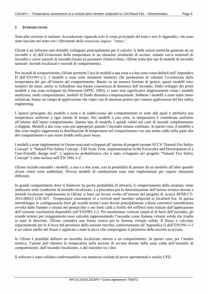
La barra del menu contiene: “File”, “Strumenti”, “Vista” e “Aiuto” (vedi Fig. 1).
Fig. 1 Finestra principale – Barra menu
Per salvare l’analisi corrente in un file, selezionare “Salva analisi” dal menu a tendina “File”.
Per salvare un’analisi precedentemente archiviata con un altro nome, selezionare il comando “Salva Analisi
come…” dal menu a tendina “File”.
Entrambi i comandi apriranno la finestra di dialogo “Save As” nella quale l’utente può selezionare la cartella
e il nome nella riga File Name. L’analisi sarà salvata con l’estensione *.ozn.
Per iniziare una nuova analisi, selezionare il comando “Nuova Analisi” dal menu “File”.
Il comando “Imposta Pagina” dal menu “File” aprirà la finestra di dialogo nella quale l’utente può selezionare
la dimensione della pagina, l’orientazione e i margini dell’area di stampa.
Nel menu “Strumenti”, l’utente può aggiungere o cambiare i materiali delle proprietà termiche della
compartimentazione selezionando il comando “Aggiungi Materiale di Partizione”.
Per aggiungere o cambiare i materiali di protezione al fuoco, selezionare il comando “Aggiungi Materiale di
Isolamento dell’Acciaio”.
Non è possibile cambiare il materiale della partizione o della protezione al fuoco dell’acciaio a meno che
non si lanci una nuova analisi.
L’ultimo comando nel menu strumenti è il comando Language.
Per cambiare la lingua in OZone, selezionare il comando “Language” dal menu “Strumenti” e scegliere la
lingua desiderata dal menu a tendina “Select Language”.
Il menu Vista contiene i comandi per mostrare sia i dati dell’analisi (RHR - Dati, Tasso di Pirolisi - Dati), o
i risultati nei grafici (RHR - Calcolata, Tasso di Pirolisi - Calcolato, Temperatura della Zona Calda, etc). Non
tutti i comandi sono attivi nel menu Vista in quanto dipende dallo status dell’analisi. Per esempio, se si
calcola la temperatura dell’acciaio, il comando “Temperatura dell’Acciaio” viene attivato.
LOCAFI+ – Temperature assessment of a vertical steel member subjected to LOCAlised Fire – Dissemination Page 11
RFCS-2016“LOCAFI+”-Grant Agreement 754072
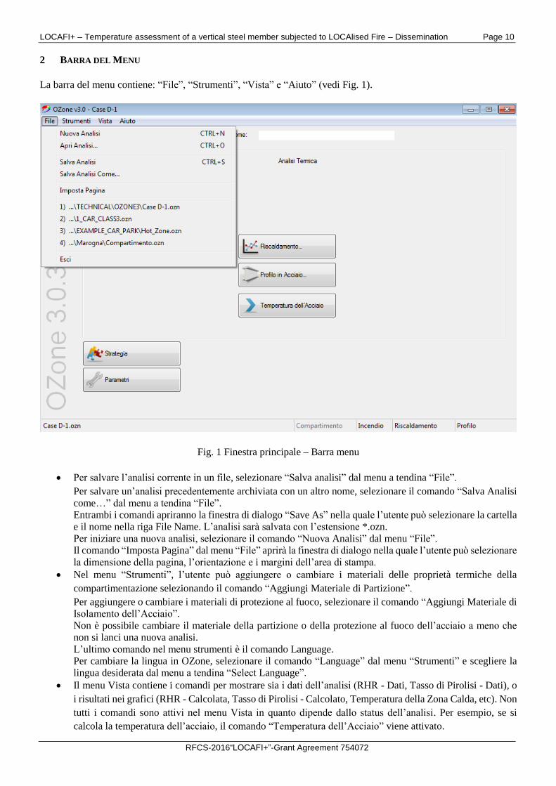
L’ultimo comando del menu Vista crea un report dell’analisi corrente. Il report viene salvato in un documento
Microsoft Word nella stessa cartella ove è presente il file dell’analisi e con lo stesso nome, benché con
estensione diversa. Il grafico dei dati può essere esportato in Excel cliccando il tasto destro in un qualsiasi
punto del grafico e selezionando poi “Copy Chart”. Passando poi a Excel e selezionando Incolla, i dati
vengono inseriti nello spreadsheet (vedi Fig. 2).
Fig. 2 Finestra Grafico
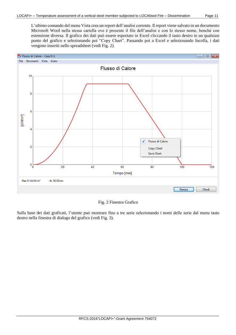
Sulla base dei dati graficati, l’utente può mostrare fino a tre serie selezionando i nomi delle serie dal menu tasto
destro nella finestra di dialogo del grafico (vedi Fig. 3).
LOCAFI+ – Temperature assessment of a vertical steel member subjected to LOCAlised Fire – Dissemination Page 12
RFCS-2016“LOCAFI+”-Grant Agreement 754072
Fig. 3 Finestra grafico
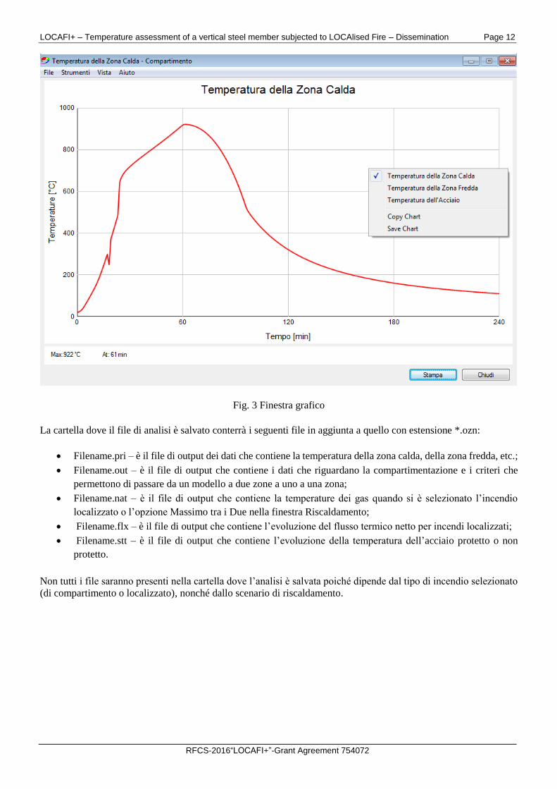
La cartella dove il file di analisi è salvato conterrà i seguenti file in aggiunta a quello con estensione *.ozn:
Filename.pri – è il file di output dei dati che contiene la temperatura della zona calda, della zona fredda, etc.;
Filename.out – è il file di output che contiene i dati che riguardano la compartimentazione e i criteri che
permettono di passare da un modello a due zone a uno a una zona;
Filename.nat – è il file di output che contiene la temperature dei gas quando si è selezionato l’incendio
localizzato o l’opzione Massimo tra i Due nella finestra Riscaldamento;
Filename.flx – è il file di output che contiene l’evoluzione del flusso termico netto per incendi localizzati;
Filename.stt – è il file di output che contiene l’evoluzione della temperatura dell’acciaio protetto o non
protetto.
Non tutti i file saranno presenti nella cartella dove l’analisi è salvata poiché dipende dal tipo di incendio selezionato
(di compartimento o localizzato), nonché dallo scenario di riscaldamento.
LOCAFI+ – Temperature assessment of a vertical steel member subjected to LOCAlised Fire – Dissemination Page 13
RFCS-2016“LOCAFI+”-Grant Agreement 754072
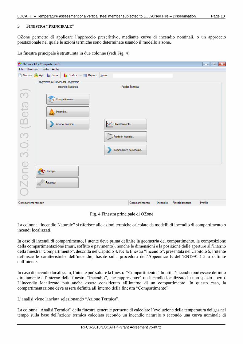
3 FINESTRA “PRINCIPALE”
OZone permette di applicare l’approccio prescrittivo, mediante curve di incendio nominali, o un approccio
prestazionale nel quale le azioni termiche sono determinate usando il modello a zone.
La finestra principale è strutturata in due colonne (vedi Fig. 4).
Fig. 4 Finestra principale di OZone
La colonna “Incendio Naturale” si riferisce alle azioni termiche calcolate da modelli di incendio di compartimento o
incendi localizzati.
In caso di incendi di compartimento, l’utente deve prima definire la geometria del compartimento, la composizione
della compartimentazione (muri, soffitto e pavimento), nonché le dimensioni e la posizione delle aperture all’interno
della finestra “Compartimento”, descritta nel Capitolo 4. Nella finestra “Incendio”, presentata nel Capitolo 5, l’utente
definisce le caratteristiche dell’incendio, basate sulla procedura dell’Appendice E dell’EN1991-1-2 o definite
dall’utente.
In caso di incendio localizzato, l’utente può saltare la finestra “Compartimento”. Infatti, l’incendio può essere definito
direttamente all’interno della finestra “Incendio”, che rappresenterà un incendio localizzato in uno spazio aperto.
L’incendio localizzato può anche essere considerato all’interno di un compartimento. In questo caso, la
compartimentazione deve essere definita all’interno della finestra “Compartimento”.
L’analisi viene lanciata selezionando “Azione Termica”.
La colonna “Analisi Termica” della finestra generale permette di calcolare l’evoluzione della temperatura dei gas nel
tempo sulla base dell’azione termica calcolata secondo un incendio naturale o secondo una curva nominale di
LOCAFI+ – Temperature assessment of a vertical steel member subjected to LOCAlised Fire – Dissemination Page 14
RFCS-2016“LOCAFI+”-Grant Agreement 754072
incendio. La selezione dell’azione termica (curva nominale, incendio di compartimento, incendio localizzato)
avviene nella finestra “Riscaldamento”.
In caso dell’azione termica precedentemente determinata usando modelli di incendio naturali, il profilo di acciaio
può essere riscaldato considerando nella finestra “Riscaldamento” la temperatura della zona calda (da un incendio di
compartimento) o la temperatura di un incendio localizzato.
Se le caratteristiche della compartimentazione sono definite nella finestra “Compartimento”, e un incendio
localizzato è definito nella finestra “Incendio”, l’utente può anche considerare il riscaldamento del profilo di acciaio
come massimo tra il flusso termico della zona calda (incendio di compartimento) e quello dell’incendio localizzato.
In caso di curva nominale di incendio, non c’è bisogno di passare attraverso le prima colonna “Incendio Naturale”
della finestra generale. L’utente seleziona direttamente la curva nominale nella finestra “Riscaldamento”.
Il profilo protetto/non protetto è definito nella finestra “Profilo in Acciaio”. L’analisi termica nel profilo è svolta
selezionando “Temperatura dell’Acciaio”.
Le finestre “Strategia” e i “Parametri” sono descritte nei Capitoli 6 e 7.
LOCAFI+ – Temperature assessment of a vertical steel member subjected to LOCAlised Fire – Dissemination Page 15
RFCS-2016“LOCAFI+”-Grant Agreement 754072
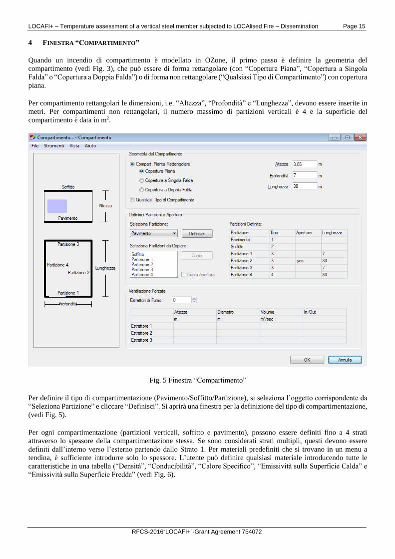
4 FINESTRA “COMPARTIMENTO”
Quando un incendio di compartimento è modellato in OZone, il primo passo è definire la geometria del
compartimento (vedi Fig. 3), che può essere di forma rettangolare (con “Copertura Piana”, “Copertura a Singola
Falda” o “Copertura a Doppia Falda”) o di forma non rettangolare (“Qualsiasi Tipo di Compartimento”) con copertura
piana.
Per compartimento rettangolari le dimensioni, i.e. “Altezza”, “Profondità” e “Lunghezza”, devono essere inserite in
metri. Per compartimenti non rettangolari, il numero massimo di partizioni verticali è 4 e la superficie del
compartimento è data in m2.
Fig. 5 Finestra “Compartimento”
Per definire il tipo di compartimentazione (Pavimento/Soffitto/Partizione), si seleziona l’oggetto corrispondente da
“Seleziona Partizione” e cliccare “Definisci”. Si aprirà una finestra per la definizione del tipo di compartimentazione,
(vedi Fig. 5).
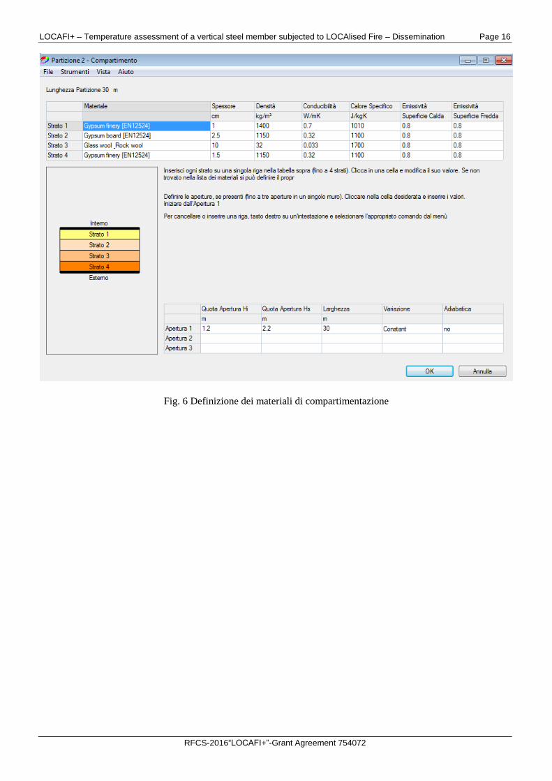
Per ogni compartimentazione (partizioni verticali, soffitto e pavimento), possono essere definiti fino a 4 strati
attraverso lo spessore della compartimentazione stessa. Se sono considerati strati multipli, questi devono essere
definiti dall’interno verso l’esterno partendo dallo Strato 1. Per materiali predefiniti che si trovano in un menu a
tendina, è sufficiente introdurre solo lo spessore. L’utente può definire qualsiasi materiale introducendo tutte le
caratteristiche in una tabella (“Densità”, “Conducibilità”, “Calore Specifico”, “Emissività sulla Superficie Calda” e
“Emissività sulla Superficie Fredda” (vedi Fig. 6).
LOCAFI+ – Temperature assessment of a vertical steel member subjected to LOCAlised Fire – Dissemination Page 16
RFCS-2016“LOCAFI+”-Grant Agreement 754072
Fig. 6 Definizione dei materiali di compartimentazione
LOCAFI+ – Temperature assessment of a vertical steel member subjected to LOCAlised Fire – Dissemination Page 17
RFCS-2016“LOCAFI+”-Grant Agreement 754072
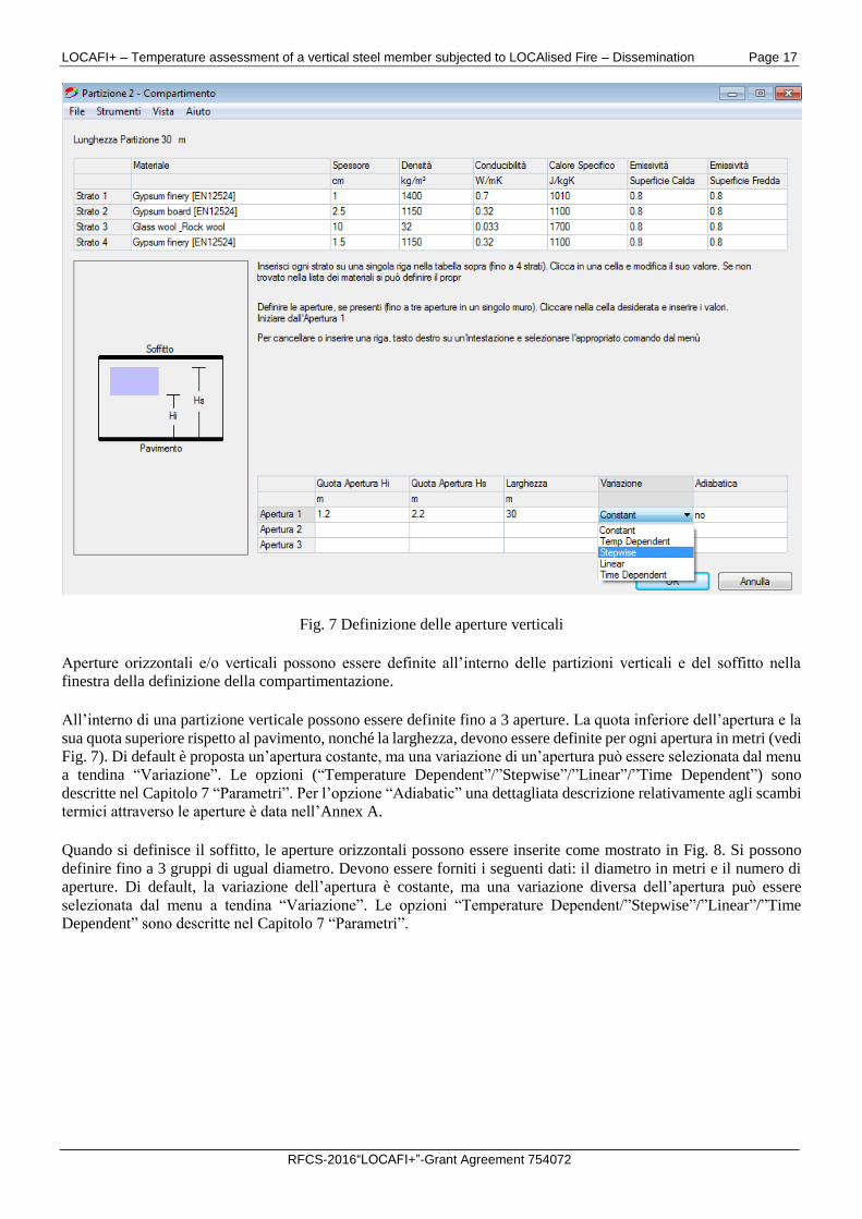
Fig. 7 Definizione delle aperture verticali
Aperture orizzontali e/o verticali possono essere definite all’interno delle partizioni verticali e del soffitto nella
finestra della definizione della compartimentazione.
All’interno di una partizione verticale possono essere definite fino a 3 aperture. La quota inferiore dell’apertura e la
sua quota superiore rispetto al pavimento, nonché la larghezza, devono essere definite per ogni apertura in metri (vedi
Fig. 7). Di default è proposta un’apertura costante, ma una variazione di un’apertura può essere selezionata dal menu
a tendina “Variazione”. Le opzioni (“Temperature Dependent”/”Stepwise”/”Linear”/”Time Dependent”) sono
descritte nel Capitolo 7 “Parametri”. Per l’opzione “Adiabatic” una dettagliata descrizione relativamente agli scambi
termici attraverso le aperture è data nell’Annex A.
Quando si definisce il soffitto, le aperture orizzontali possono essere inserite come mostrato in Fig. 8. Si possono
definire fino a 3 gruppi di ugual diametro. Devono essere forniti i seguenti dati: il diametro in metri e il numero di
aperture. Di default, la variazione dell’apertura è costante, ma una variazione diversa dell’apertura può essere
selezionata dal menu a tendina “Variazione”. Le opzioni “Temperature Dependent/”Stepwise”/”Linear”/”Time
Dependent” sono descritte nel Capitolo 7 “Parametri”.
LOCAFI+ – Temperature assessment of a vertical steel member subjected to LOCAlised Fire – Dissemination Page 18
RFCS-2016“LOCAFI+”-Grant Agreement 754072
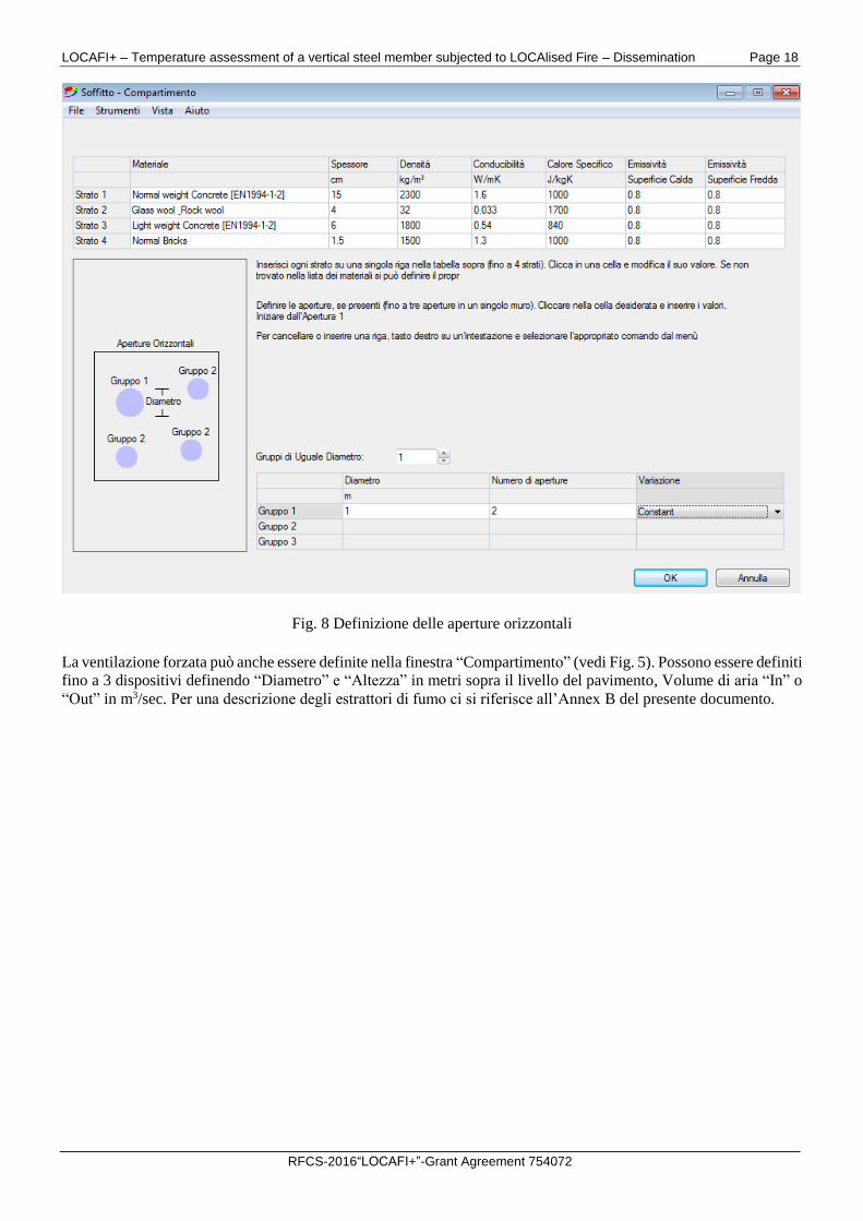
Fig. 8 Definizione delle aperture orizzontali
La ventilazione forzata può anche essere definite nella finestra “Compartimento” (vedi Fig. 5). Possono essere definiti
fino a 3 dispositivi definendo “Diametro” e “Altezza” in metri sopra il livello del pavimento, Volume di aria “In” o
“Out” in m3/sec. Per una descrizione degli estrattori di fumo ci si riferisce all’Annex B del presente documento.
LOCAFI+ – Temperature assessment of a vertical steel member subjected to LOCAlised Fire – Dissemination Page 19
RFCS-2016“LOCAFI+”-Grant Agreement 754072
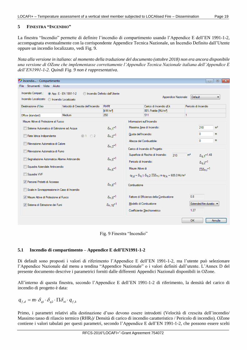
5 FINESTRA “INCENDIO”
La finestra “Incendio” permette di definire l’incendio di compartimento usando l’Appendice E dell’EN 1991-1-2,
accompagnata eventualmente con la corrispondente Appendice Tecnica Nazionale, un Incendio Definito dall’Utente
oppure un incendio localizzato, vedi Fig. 9.
Nota alla versione in italiano: al momento della traduzione del documento (ottobre 2018) non era ancora disponibile
una versione di OZone che implementasse correttamente l’Appendice Tecnica Nazionale italiana dell’Appendice E
dell’EN1991-1-2. Quindi Fig. 9 non è rappresentativa.
Fig. 9 Finestra “Incendio”
5.1 Incendio di compartimento – Appendice E dell’EN1991-1-2
Di default sono proposti i valori di riferimento l’Appendice E dell’EN 1991-1-2, ma l’utente può selezionare
l’Appendice Nazionale dal menu a tendina “Appendice Nazionale” o i valori definiti dall’utente. L’Annex D del
presente documento descrive i parametrici forniti dalle differenti Appendici Nazionali disponibili in OZone.
All’interno di questa finestra, secondo l’Appendice E dell’EN 1991-1-2 di riferimento, la densità del carico di
incendio di progetto è data:
kfniqqdf qmq ,21,
Primo, i parametri relativi alla destinazione d’uso devono essere introdotti (Velocità di crescita dell’incendio/
Massimo tasso di rilascio termico (RHRf)/ Densità di carico di incendio caratteristico / Pericolo di incendio). OZone
contiene i valori tabulati per questi parametri, secondo l’Appendice E dell’EN 1991-1-2, che possono essere scelti
LOCAFI+ – Temperature assessment of a vertical steel member subjected to LOCAlised Fire – Dissemination Page 20
RFCS-2016“LOCAFI+”-Grant Agreement 754072
dal menu a tendina “Destinazione d’Uso”. Se sono necessari degli altri valori, l’utente può selezionare “User
Defined” dallo stesso menu a tendina.
Il valore caratteristico di densità di carico di incendio qfk è l’80% frattile della distribuzione di densità del carico di
incendio ottenuta da una ricerca su compartimenti esistenti. I dati sono disponibili per differenti tipi di destinazioni
d’uso. Per ottenere la densità del carico di incendio caratteristico, è stata misurata la massa di combustibile presente
nei compartimenti, poi moltiplicata per il potere calorifico del combustibile e infine divisa per l’area del
compartimento. In queste valutazioni è stata considerata la combustione completa.
La fase crescente dell’incendio è caratterizzata dalla velocità di crescita dell’incendio tα, che rappresenta il tempo al
quale l’area di incendio Af è cresciuta fino a un valore che determina una RHR di 1 MW.
Il valore massimo del tasso di rilascio termico (RHRf) è la quantità massima di energia che può essere rilasciata da
un’area unitaria di incendio nella situazione di incendio controllato dalla ventilazione. Il valore RHRf è dato
nell’Appendice E dell’EN1991-1-2 per differenti destinazioni d’uso. I valori di RHRf rappresentano incendi reali e
tengono in conto della combustione incompleta.
La velocità di crescita dell’incendio, il valore di RHRf e la densità di incendio caratteristica sono dati nell’Appendice
E dell’EN1991-1-2 in funzione della destinazione d’uso.
L’influenza del pericolo di attivazione dell’incendio è tenuto conto dal fattore 2q fornito dall’Appendice E
dell’EN1991-1-2.
L’influenza delle misure attive di protezione antincendio sono date dai fattori in, fornito dall’Appendice E
dell’EN1991-1-2. L’utente può selezionare/deselezionare le opzioni all’interno del riquadro delle Misure Attive di
Protezione al Fuoco sulla base della loro presenza o meno.
L’influenza dell’area del compartimento è tenuta in conto dal fattore 1q , automaticamente calcolato sulla base
dell’area del compartimento. I valori di 1q sono approssimati dall’Eq. (1). Questa legge è stata ottenuta da un
fitting dei valori tabulati nella tabella E1 dell’EN 1991-1-2.
5752.0ln1688.01 fq A (1)
L’area massima di incendio Afi,max è la massima area di combustibile che brucia, vale a dire l’area massima sulla
quale si estende il combustibile. Nella maggior parte dei casi, la massima superficie di incendio può essere
considerata uguale alla superficie del compartimento. Di default OZone considera questo valore sulla base del
calcolo nella finestra “Compartimento”. L’utente può tuttavia considerare valori differenti per la massima superficie
massima di incendio, che può essere più piccola dell’area del compartimento.
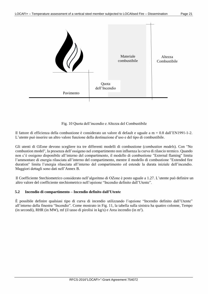
La quota dell’incendio è considerata di default a livello del pavimento. L’utente può comunque inserire una quota
differente (vedi Fig. 10). Ciò può influenzare i criteri di flash-over come descritto nell’Annex F.
L’altezza del combustibile è considerata di default al livello del pavimento. L’utente può definire una differente
altezza massima del combustibile all’interno del compartimento (vedi Fig. 10). Ciò può influenzare i criteri di flash-
over come descritto in Annex F.
LOCAFI+ – Temperature assessment of a vertical steel member subjected to LOCAlised Fire – Dissemination Page 21
RFCS-2016“LOCAFI+”-Grant Agreement 754072
Fig. 10 Quota dell’incendio e Altezza del Combustibile
Il fattore di efficienza della combustione è considerato un valore di default e uguale a m = 0.8 dall’EN1991-1-2.
L’utente può inserire un altro valore funzione della destinazione d’uso e del tipo di combustibile.
Gli utenti di OZone devono scegliere tra tre differenti modelli di combustione (combustion models). Con "No
combustion model", la presenza dell’ossigeno nel compartimento non influenza la curva di rilascio termico. Quando
non c’è ossigeno disponibile all’interno del compartimento, il modello di combustione "External flaming" limita
l’ammontare di energia rilasciata all’interno del compartimento, mentre il modello di combustione "Extended fire
duration" limita l’energia rilasciata all’interno del compartimento ed estende la durata iniziale dell’incendio.
Maggiori dettagli sono dati nell’Annex B.
Il Coefficiente Stechiometrico considerato nell’algoritmo di OZone è posto uguale a 1.27. L’utente può definire un
altro valore del coefficiente stechiometrico nell’opzione “Incendio definito dall’Utente”.
5.2 Incendio di compartimento – Incendio definito dall’Utente
È possibile definire qualsiasi tipo di curva di incendio utilizzando l’opzione “Incendio definito dall’Utente”
all’interno della finestra “Incendio”. Come mostrato in Fig. 11, la tabella sulla sinistra ha quattro colonne, Tempo
(in secondi), RHR (in MW), mf (il tasso di pirolisi in kg/s) e Area incendio (in m2).
Materiale
combustibile
Pavimento
Quota
dell’Incendio
Altezza
Combustibile
LOCAFI+ – Temperature assessment of a vertical steel member subjected to LOCAlised Fire – Dissemination Page 22
RFCS-2016“LOCAFI+”-Grant Agreement 754072
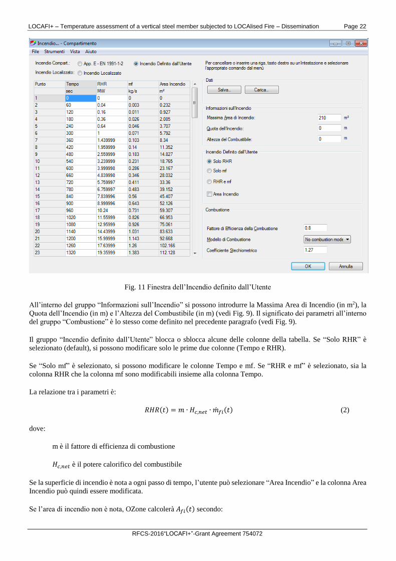
Fig. 11 Finestra dell’Incendio definito dall’Utente
All’interno del gruppo “Informazioni sull’Incendio” si possono introdurre la Massima Area di Incendio (in m2), la
Quota dell’Incendio (in m) e l’Altezza del Combustibile (in m) (vedi Fig. 9). Il significato dei parametri all’interno
del gruppo “Combustione” è lo stesso come definito nel precedente paragrafo (vedi Fig. 9).
Il gruppo “Incendio definito dall’Utente” blocca o sblocca alcune delle colonne della tabella. Se “Solo RHR” è
selezionato (default), si possono modificare solo le prime due colonne (Tempo e RHR).
Se “Solo mf” è selezionato, si possono modificare le colonne Tempo e mf. Se “RHR e mf” è selezionato, sia la
colonna RHR che la colonna mf sono modificabili insieme alla colonna Tempo.
La relazione tra i parametri è:
𝑅𝐻𝑅(𝑡) = 𝑚 ∙ 𝐻𝑐,𝑛𝑒𝑡 ∙ �̇�𝑓𝑖(𝑡) (2)
dove:
m è il fattore di efficienza di combustione
𝐻𝑐,𝑛𝑒𝑡 è il potere calorifico del combustibile
Se la superficie di incendio è nota a ogni passo di tempo, l’utente può selezionare “Area Incendio” e la colonna Area
Incendio può quindi essere modificata.
Se l’area di incendio non è nota, OZone calcolerà 𝐴𝑓𝑖(𝑡) secondo:
LOCAFI+ – Temperature assessment of a vertical steel member subjected to LOCAlised Fire – Dissemination Page 23
RFCS-2016“LOCAFI+”-Grant Agreement 754072
𝐴𝑓𝑖(𝑡) = 𝐴𝑓𝑖,𝑚𝑎𝑥 ∙𝑅𝐻𝑅(𝑡)
𝑅𝐻𝑅𝑚𝑎𝑥 (3)
dove:
Afi,max è la massima area di incendio definita all’interno del gruppo “Informazioni sull’Incendio”.
Quattro scenari sono possibili.
Caso 1. RHR, mf e Area Incendio sono dati dall’utente all’interno della tabella
Quando tutti i dati sono disponibili in funzione del tempo, l’utente può inserirli nelle colonne corrispondenti. Questo
caso corrisponde a prove sperimentali per le quali si sono misurate la perdita di massa e la curva di rilascio termico,
quest’ultima calcolata tramite la misura del consumo di ossigeno nello strato superiore dei gas del dispositivo di
estrazione. L’area di incendio è anche nota a ogni istante di tempo. In questa situazione, non è possibile usare nessun
modello di combustione.
Caso 2. RHR e mf sono date dall’utente all’interno della tabella
Questo caso corrisponde alle prove sperimentali per le quali si è misurata la perdita di massa e la curva di rilascio
termico. L’area di incendio non è nota ed è ipotizzata proporzionale alla curva di rilascio termico. In questo caso
non è possibile usare un modello di combustione.
Caso 3. RHR o mf e anche l’area di incendio sono dati dall’utente all’interno della tabella
Questo caso corrisponde alle prove sperimentali dove la perdita di massa o la curva di rilascio termico sono state
misurate. Le quantità incognite sono determinate sulla base delle Eq. (2) e Eq. (3). La superficie dell’incendio è nota
a ogni istante di tempo. In questo caso, non è possibile utilizzare un modello di combustione.
Caso 4. RHR o mf sono dati dall’utente all’interno della tabella
Questo caso corrisponde alle prove per le quali la perdita di massa o la curva di rilascio termico sono state misurate.
La superficie di incendio non è nota ed è ipotizzata proporzionale alla curva di rilascio termico. Le quantità non note
sono calcolate sulla base delle Eq. (2) e Eq. (3). I modelli di combustione possono essere o non essere usati.
L’utente può importare o esportare i dati dalla tabella. Per importare i dati, un file di tipo testo deve essere
organizzato con i dati in due, tre o quattro colonne rispettando lo stesso ordine della tabella. La prima colonna deve
contenere il tempo in secondi. Almeno due colonne devono essere definite, per esempio il tempo e la RHR. Il
separatore dei dati deve essere uno spazio.
5.3 Incendio localizzato
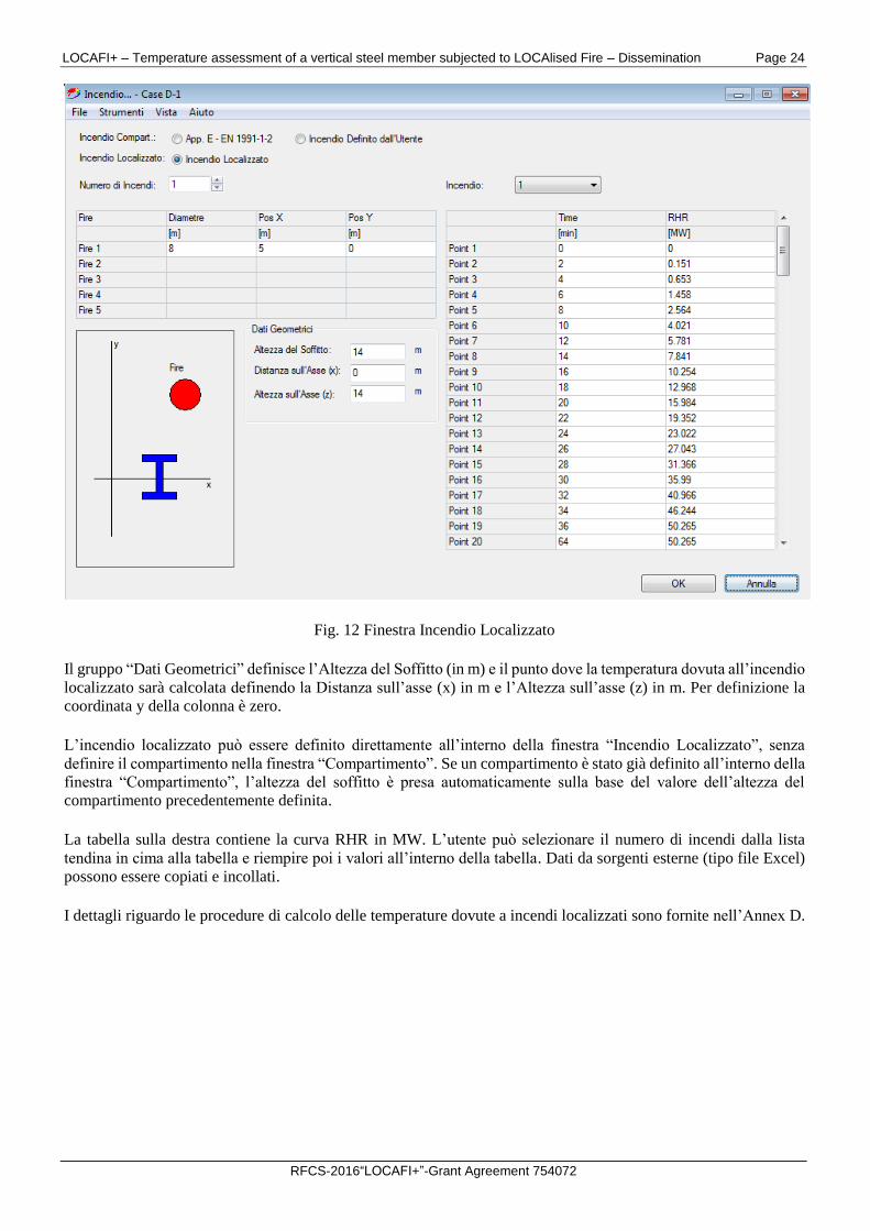
Possono essere definiti fino a cinque incendi localizzati, come mostrato in Fig. 12. La tabella in alto a destra contiene
il diametro (o i diametri) in m e la posizione all’interno del compartimento sulla base delle coordinate x e y in (m).
LOCAFI+ – Temperature assessment of a vertical steel member subjected to LOCAlised Fire – Dissemination Page 24
RFCS-2016“LOCAFI+”-Grant Agreement 754072
Fig. 12 Finestra Incendio Localizzato
Il gruppo “Dati Geometrici” definisce l’Altezza del Soffitto (in m) e il punto dove la temperatura dovuta all’incendio
localizzato sarà calcolata definendo la Distanza sull’asse (x) in m e l’Altezza sull’asse (z) in m. Per definizione la
coordinata y della colonna è zero.
L’incendio localizzato può essere definito direttamente all’interno della finestra “Incendio Localizzato”, senza
definire il compartimento nella finestra “Compartimento”. Se un compartimento è stato già definito all’interno della
finestra “Compartimento”, l’altezza del soffitto è presa automaticamente sulla base del valore dell’altezza del
compartimento precedentemente definita.
La tabella sulla destra contiene la curva RHR in MW. L’utente può selezionare il numero di incendi dalla lista
tendina in cima alla tabella e riempire poi i valori all’interno della tabella. Dati da sorgenti esterne (tipo file Excel)
possono essere copiati e incollati.
I dettagli riguardo le procedure di calcolo delle temperature dovute a incendi localizzati sono fornite nell’Annex D.
LOCAFI+ – Temperature assessment of a vertical steel member subjected to LOCAlised Fire – Dissemination Page 25
RFCS-2016“LOCAFI+”-Grant Agreement 754072
6 FINESTRA “STRATEGIA”
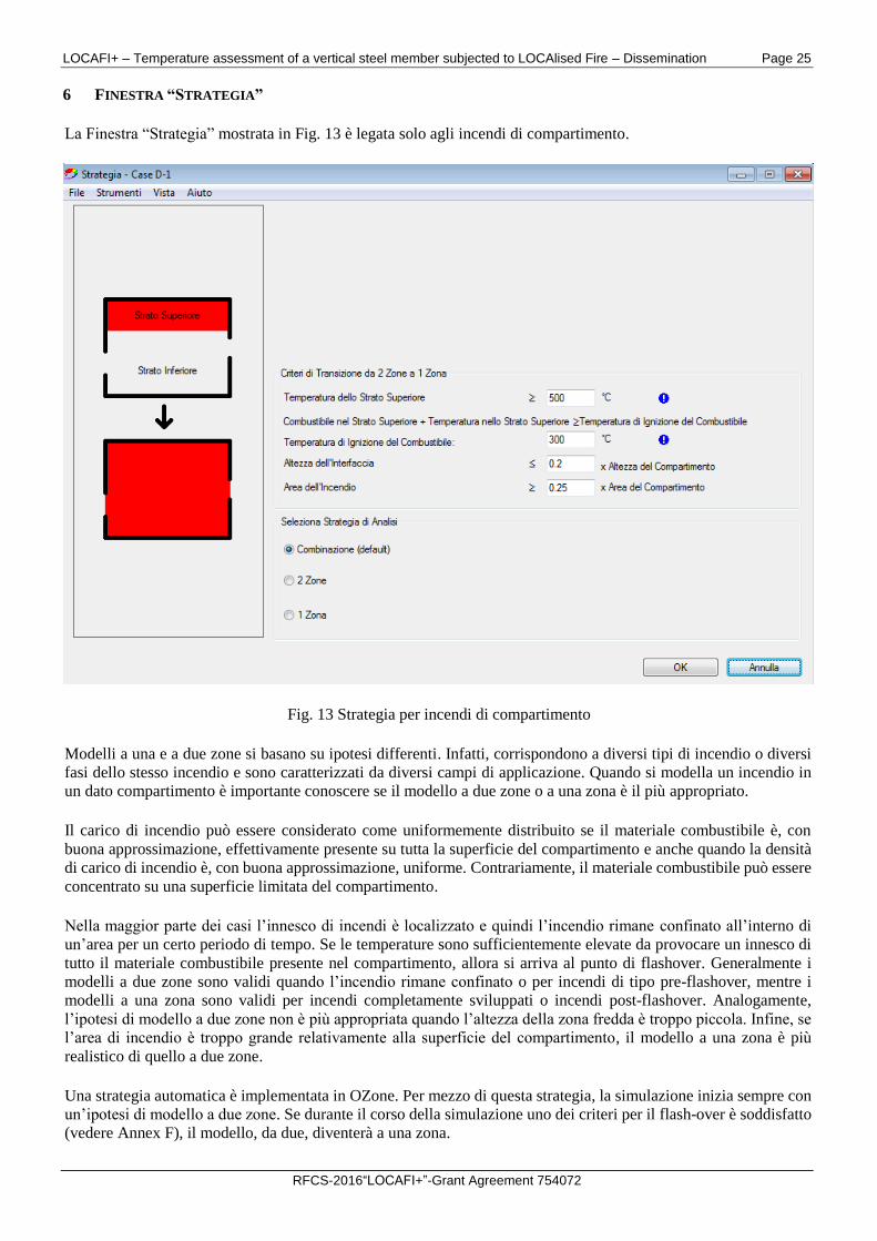
La Finestra “Strategia” mostrata in Fig. 13 è legata solo agli incendi di compartimento.
Fig. 13 Strategia per incendi di compartimento
Modelli a una e a due zone si basano su ipotesi differenti. Infatti, corrispondono a diversi tipi di incendio o diversi
fasi dello stesso incendio e sono caratterizzati da diversi campi di applicazione. Quando si modella un incendio in
un dato compartimento è importante conoscere se il modello a due zone o a una zona è il più appropriato.
Il carico di incendio può essere considerato come uniformemente distribuito se il materiale combustibile è, con
buona approssimazione, effettivamente presente su tutta la superficie del compartimento e anche quando la densità
di carico di incendio è, con buona approssimazione, uniforme. Contrariamente, il materiale combustibile può essere
concentrato su una superficie limitata del compartimento.
Nella maggior parte dei casi l’innesco di incendi è localizzato e quindi l’incendio rimane confinato all’interno di
un’area per un certo periodo di tempo. Se le temperature sono sufficientemente elevate da provocare un innesco di
tutto il materiale combustibile presente nel compartimento, allora si arriva al punto di flashover. Generalmente i
modelli a due zone sono validi quando l’incendio rimane confinato o per incendi di tipo pre-flashover, mentre i
modelli a una zona sono validi per incendi completamente sviluppati o incendi post-flashover. Analogamente,
l’ipotesi di modello a due zone non è più appropriata quando l’altezza della zona fredda è troppo piccola. Infine, se
l’area di incendio è troppo grande relativamente alla superficie del compartimento, il modello a una zona è più
realistico di quello a due zone.
Una strategia automatica è implementata in OZone. Per mezzo di questa strategia, la simulazione inizia sempre con
un’ipotesi di modello a due zone. Se durante il corso della simulazione uno dei criteri per il flash-over è soddisfatto
(vedere Annex F), il modello, da due, diventerà a una zona.
LOCAFI+ – Temperature assessment of a vertical steel member subjected to LOCAlised Fire – Dissemination Page 26
RFCS-2016“LOCAFI+”-Grant Agreement 754072
All’interno del gruppo “Seleziona Strategia di Analisi”, l’utente può imporre l’uso di un modello a una o a due zone,
o lasciare la combinazione di default tra i due modelli.
All’interno del gruppo “Criteri di Transizione da 2 Zone a 1 Zona”, l’utente può cambiare i valori di quattro
parametri che controllano il cambio di strategia dal modello a due zone al modello a una zona. È consigliato di
lasciare questi valori inalterati, a meno che non ci siano dei dati disponibili. I criteri di transizione da un modello a
due zone a uno a una zona, e le relative conseguenze sul modello di incendio, sono discussi nell’Annex F. Le
modifiche alle variabili principali e alle equazioni di base sono presentate in dettaglio sempre nell’Annex F.
LOCAFI+ – Temperature assessment of a vertical steel member subjected to LOCAlised Fire – Dissemination Page 27
RFCS-2016“LOCAFI+”-Grant Agreement 754072
7 FINESTRA “PARAMETRI”
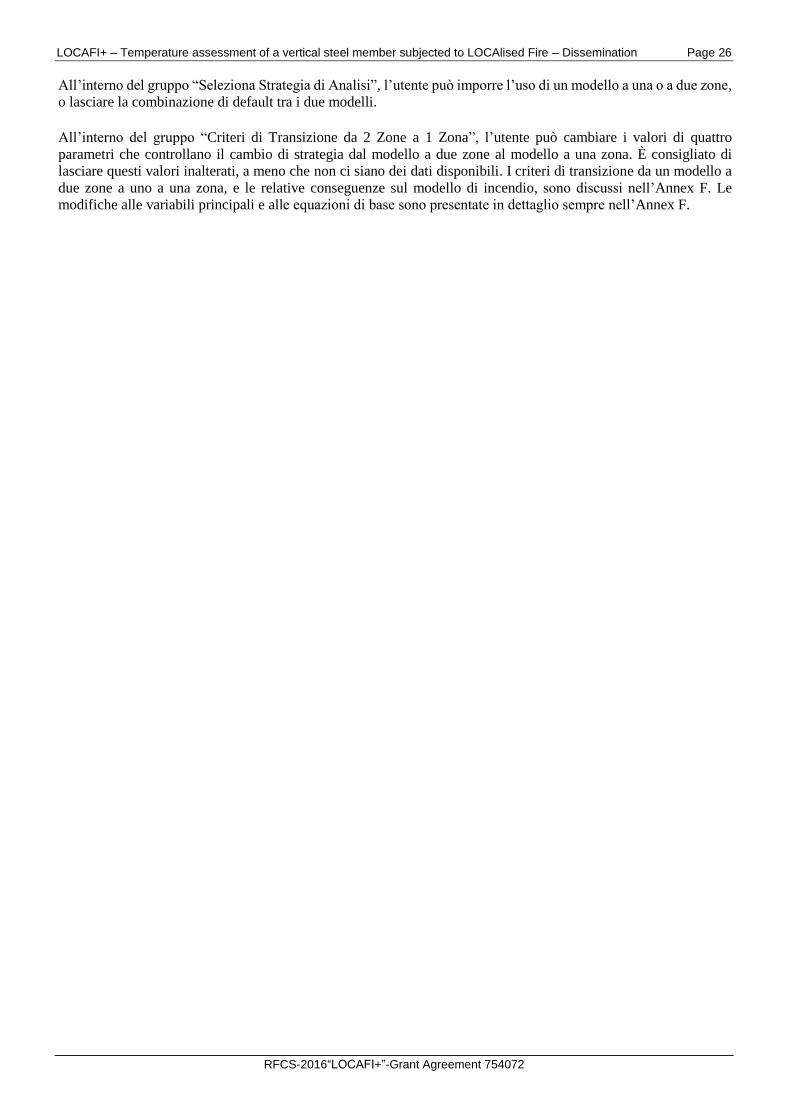
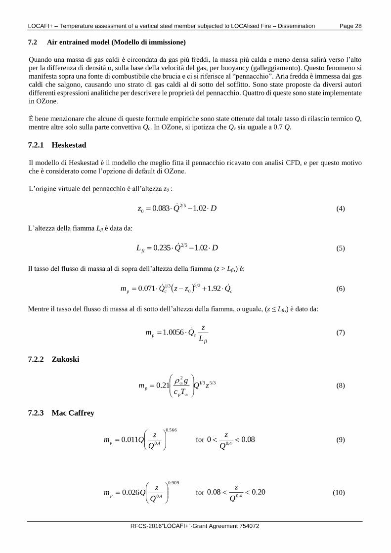
La maggior parte dei parametri usati nei calcoli sono dati in questa finestra, come illustrato in Fig. 14.
Fig. 14 Finestra “Parametri”
7.1 Parametri generali
Sul lato sinistro della finestra, i seguenti parametri sono forniti con i relativi valori di default:
Irraggiamento attraverso aperture chiuse: il valore di default da letteratura è 0.8;
Coefficiente di Bernoulli: il valore di default da letteratura è 0.7;
Caratteristiche fisiche del compartimento: temperatura iniziale 20oC e pressione iniziale 100000 Pa;
Caratteristiche del materiale della partizione: coefficiente di convezione sulla superficie calda e fredda sono
dati in accordo all’EN1991-1-2. Questi parametri si riferiscono solamente a modelli di incendio naturali. Per
modelli di incendio nominali la finestra “Riscaldamento” fa uso dei valori forniti dall’EN1991-1-2;
Parametri di calcolo: di default il tempo di analisi è di due ore ed è consigliato mantenere il valore massimo
del passo di tempo pari a 10 secondi;
Coefficiente parziale di sicurezza in condizioni di incendio: valore di default secondo l’EN1991-1-2, i.e. 1.0.
LOCAFI+ – Temperature assessment of a vertical steel member subjected to LOCAlised Fire – Dissemination Page 28
RFCS-2016“LOCAFI+”-Grant Agreement 754072
7.2 Air entrained model (Modello di immissione)
Quando una massa di gas caldi è circondata da gas più freddi, la massa più calda e meno densa salirà verso l’alto
per la differenza di densità o, sulla base della velocità del gas, per buoyancy (galleggiamento). Questo fenomeno si
manifesta sopra una fonte di combustibile che brucia e ci si riferisce al “pennacchio”. Aria fredda è immessa dai gas
caldi che salgono, causando uno strato di gas caldi al di sotto del soffitto. Sono state proposte da diversi autori
differenti espressioni analitiche per descrivere le proprietà del pennacchio. Quattro di queste sono state implementate
in OZone.
È bene menzionare che alcune di queste formule empiriche sono state ottenute dal totale tasso di rilascio termico Q,
mentre altre solo sulla parte convettiva Qc. In OZone, si ipotizza che Qc sia uguale a 0.7 Q.
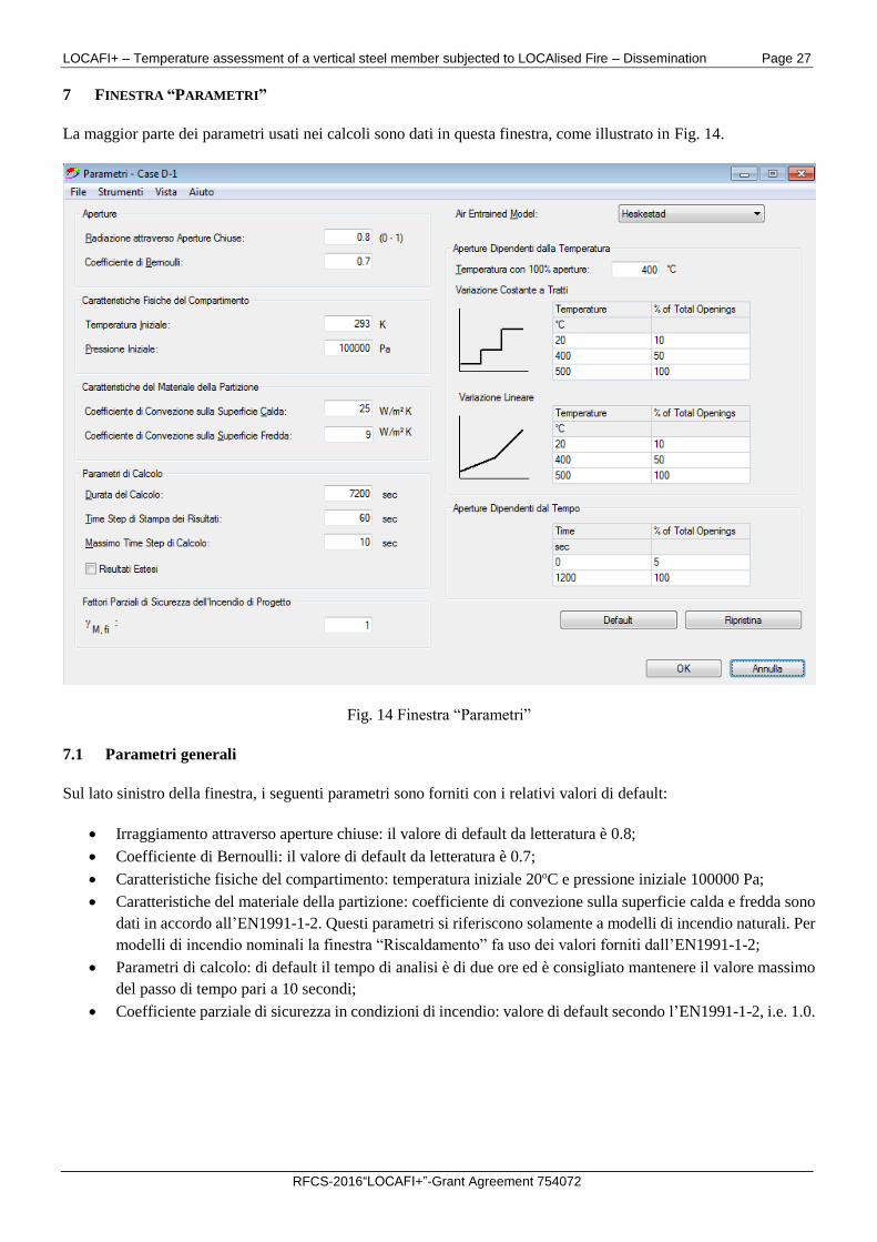
7.2.1 Heskestad
Il modello di Heskestad è il modello che meglio fitta il pennacchio ricavato con analisi CFD, e per questo motivo
che è considerato come l’opzione di default di OZone.
L’origine virtuale del pennacchio è all’altezza z0 :
DQz 02.1083.0 52
0 (4)
L’altezza della fiamma Lfl è data da:
DQL fl 02.1235.0 52 (5)
Il tasso del flusso di massa al di sopra dell’altezza della fiamma (z > Lfl,) è:
ccp QzzQm 92.1071.035
0
31 (6)
Mentre il tasso del flusso di massa al di sotto dell’altezza della fiamma, o uguale, (z ≤ Lfl,) è dato da:
fl
cpL
zQm 0056.1 (7)
7.2.2 Zukoski
3531
2
21.0 zQTc
gm
p
p
(8)
7.2.3 Mac Caffrey
566.0
4.0011.0
Q
zQmp for 08.00
4.0
Q
z (9)
909.0
4.0026.0
Q
zQm p for 20.008.0
4.0
Q
z (10)
LOCAFI+ – Temperature assessment of a vertical steel member subjected to LOCAlised Fire – Dissemination Page 29
RFCS-2016“LOCAFI+”-Grant Agreement 754072
895.1
4.0124.0
Q
zQm p for
4.020.0
Q
z (11)
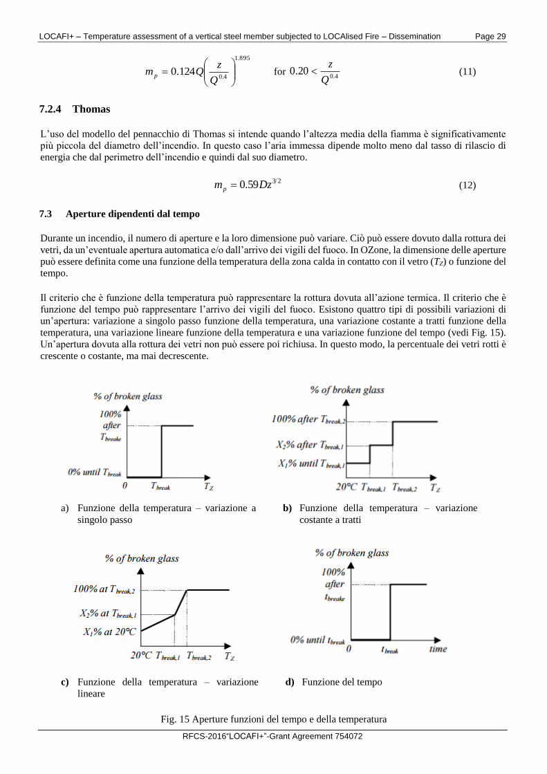
7.2.4 Thomas
L’uso del modello del pennacchio di Thomas si intende quando l’altezza media della fiamma è significativamente
più piccola del diametro dell’incendio. In questo caso l’aria immessa dipende molto meno dal tasso di rilascio di
energia che dal perimetro dell’incendio e quindi dal suo diametro.
2359.0 Dzmp (12)
7.3 Aperture dipendenti dal tempo
Durante un incendio, il numero di aperture e la loro dimensione può variare. Ciò può essere dovuto dalla rottura dei
vetri, da un’eventuale apertura automatica e/o dall’arrivo dei vigili del fuoco. In OZone, la dimensione delle aperture
può essere definita come una funzione della temperatura della zona calda in contatto con il vetro (TZ) o funzione del
tempo.
Il criterio che è funzione della temperatura può rappresentare la rottura dovuta all’azione termica. Il criterio che è
funzione del tempo può rappresentare l’arrivo dei vigili del fuoco. Esistono quattro tipi di possibili variazioni di
un’apertura: variazione a singolo passo funzione della temperatura, una variazione costante a tratti funzione della
temperatura, una variazione lineare funzione della temperatura e una variazione funzione del tempo (vedi Fig. 15).
Un’apertura dovuta alla rottura dei vetri non può essere poi richiusa. In questo modo, la percentuale dei vetri rotti è
crescente o costante, ma mai decrescente.
a) Funzione della temperatura – variazione a
singolo passo
b) Funzione della temperatura – variazione
costante a tratti
c) Funzione della temperatura – variazione
lineare
d) Funzione del tempo
Fig. 15 Aperture funzioni del tempo e della temperatura
LOCAFI+ – Temperature assessment of a vertical steel member subjected to LOCAlised Fire – Dissemination Page 30
RFCS-2016“LOCAFI+”-Grant Agreement 754072
L’EN 1991-1-2 non fa nessun riferimento alle aperture e a loro variazione durante l’incendio, sebbene la loro
influenza può risultare significativa. La norma lussemburghese ITM SST – 1551.1 è l’unico documento noto agli
sviluppatori di OZone che fornisce raccomandazioni, senza però indicare particolari specifiche. Gli sviluppatori
consigliano quindi l’uso degli scenari di Fig. 15.
LOCAFI+ – Temperature assessment of a vertical steel member subjected to LOCAlised Fire – Dissemination Page 31
RFCS-2016“LOCAFI+”-Grant Agreement 754072
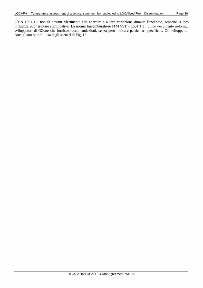
8 TASTO “AZIONE TERMICA”
Dopo la definizione del compartimento dell’incendio, l’analisi è eseguita cliccando sul tasto “Azione Termica”. I
risultati possono essere estratti dal menu “Vista”, come mostrato in Fig. 16. Un report completo dei risultati può
essere ottenuto selezionando il comando “Report”, che crea un file *.doc nella stessa cartella del file di analisi salvato
con l’estensione *.ozn.
Fig. 16 Finestra generale dopo aver cliccato sul tasto “Azione Termica”
Tutti i grafici contenuti nel file Report possono essere indipendentemente aperti nel menu “Vista”. Da queste finestre,
i dati possono essere importati in altri programmi (Excel, Word, PowerPoint, etc.), selezionando il commando “Copy
Chart” quando si clicca il tasto destro del mouse sul grafico.
LOCAFI+ – Temperature assessment of a vertical steel member subjected to LOCAlised Fire – Dissemination Page 32
RFCS-2016“LOCAFI+”-Grant Agreement 754072
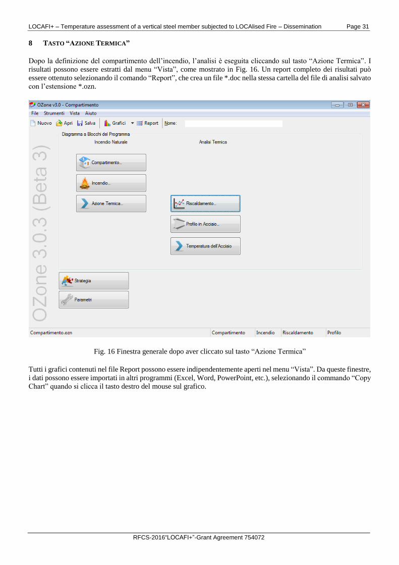
9 FINESTRA “RISCALDAMENTO”
Nella finestra “Riscaldamento” (vedere Fig. 17), l’utente può selezionare l’azione termica usata per riscaldare la
sezione definita nella finestra “Profilo in Acciaio”. Possono essere usati incendi naturali o incendi nominali.
Se si usano le curve nominali di incendio (ISO 834/ ASTM E119/ Idrocarburi) per il riscaldamento del profilo, la
definizione del compartimento e dell’incendio nella finestra generale non sono necessarie.
Fig. 17 Finestra riscaldamento
Per modelli di incendio naturale, numerosi scenari possono essere usati.
Per gli incendi di compartimento, è necessario definire sia il compartimento che le caratteristiche dell’incendio.
Quando nella finestra “Incendio” si seleziona l’“App. E – EN1991-1-2” o l’“Incendio definito dall’Utente” solo
l’opzione “Temperatura della Zona Calda” è attiva nella finestra “Riscaldamento”.
Per incendi localizzati, se nessun compartimento è definito, si ipotizza che l’incendio localizzato si sviluppi in uno
spazio aperto e solo l’opzione “Temperatura dell’Incendio Localizzato” è attiva.
Se un incendio di compartimento è definito insieme a un incendio localizzato, OZone calcola la temperatura della
zona calda e fredda nel compartimento, sulla base della strategia selezionata, considerando automaticamente la
“Massima Area di Incendio” all’interno della finestra “Incendio” come la somma di incendi localizzati nella finestra
“Incendio Localizzato”. In questo caso, l’utente può selezionare una delle tre opzioni: i) “Temperatura della Zona
Calda”; ii) “Temperatura dell’Incendio Localizzato” e iii) “Massimo tra i Due”.
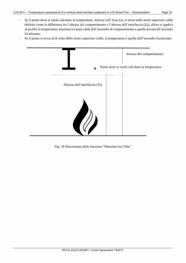
L’opzione “Massimo tra i Due” determina la temperatura massima basata sul seguente algoritmo (vedi Fig. 18):
LOCAFI+ – Temperature assessment of a vertical steel member subjected to LOCAlised Fire – Dissemination Page 33
RFCS-2016“LOCAFI+”-Grant Agreement 754072
- Se il punto dove si vuole calcolare la temperatura, Altezza sull’Asse (z), si trova nello strato superiore caldo
definito come la differenza tra l’altezza del compartimento e l’altezza dell’interfaccia (Zs), allora si applica
al profilo la temperatura massima tra zona calda dell’incendio di compartimento e quella dovuta all’incendio
localizzato;
- Se il punto si trova al di sotto dello strato superiore caldo, la temperatura è quella dell’incendio localizzato.
Fig. 18 Descrizione della funzione “Massimo tra I Due”
Altezza del compartimento
Punto dove si vuole calcolare la temperatura
Altezza dell’interfaccia (Zs)
LOCAFI+ – Temperature assessment of a vertical steel member subjected to LOCAlised Fire – Dissemination Page 34
RFCS-2016“LOCAFI+”-Grant Agreement 754072
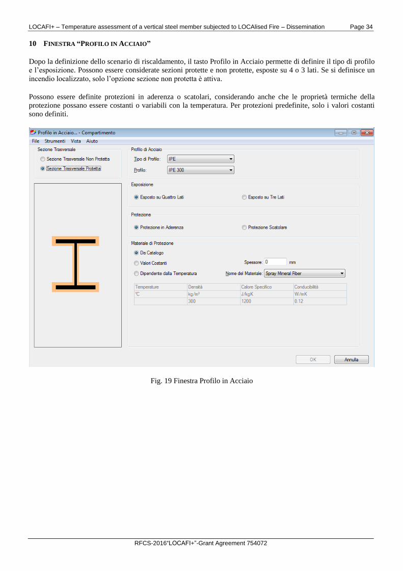
10 FINESTRA “PROFILO IN ACCIAIO”
Dopo la definizione dello scenario di riscaldamento, il tasto Profilo in Acciaio permette di definire il tipo di profilo
e l’esposizione. Possono essere considerate sezioni protette e non protette, esposte su 4 o 3 lati. Se si definisce un
incendio localizzato, solo l’opzione sezione non protetta è attiva.
Possono essere definite protezioni in aderenza o scatolari, considerando anche che le proprietà termiche della
protezione possano essere costanti o variabili con la temperatura. Per protezioni predefinite, solo i valori costanti
sono definiti.
Fig. 19 Finestra Profilo in Acciaio
LOCAFI+ – Temperature assessment of a vertical steel member subjected to LOCAlised Fire – Dissemination Page 35
RFCS-2016“LOCAFI+”-Grant Agreement 754072
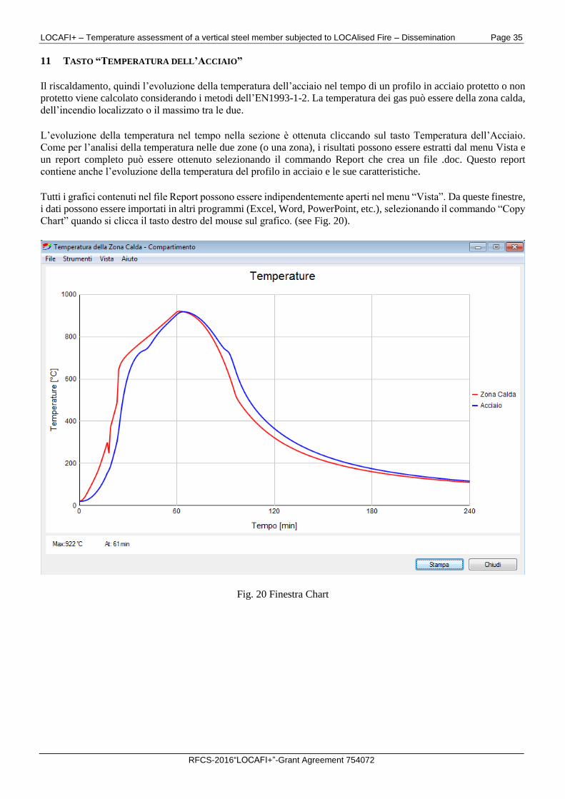
11 TASTO “TEMPERATURA DELL’ACCIAIO”
Il riscaldamento, quindi l’evoluzione della temperatura dell’acciaio nel tempo di un profilo in acciaio protetto o non
protetto viene calcolato considerando i metodi dell’EN1993-1-2. La temperatura dei gas può essere della zona calda,
dell’incendio localizzato o il massimo tra le due.
L’evoluzione della temperatura nel tempo nella sezione è ottenuta cliccando sul tasto Temperatura dell’Acciaio.
Come per l’analisi della temperatura nelle due zone (o una zona), i risultati possono essere estratti dal menu Vista e
un report completo può essere ottenuto selezionando il commando Report che crea un file .doc. Questo report
contiene anche l’evoluzione della temperatura del profilo in acciaio e le sue caratteristiche.
Tutti i grafici contenuti nel file Report possono essere indipendentemente aperti nel menu “Vista”. Da queste finestre,
i dati possono essere importati in altri programmi (Excel, Word, PowerPoint, etc.), selezionando il commando “Copy
Chart” quando si clicca il tasto destro del mouse sul grafico. (see Fig. 20).
Fig. 20 Finestra Chart
LOCAFI+ – Temperature assessment of a vertical steel member subjected to LOCAlised Fire – Dissemination Page 36
RFCS-2016“LOCAFI+”-Grant Agreement 754072
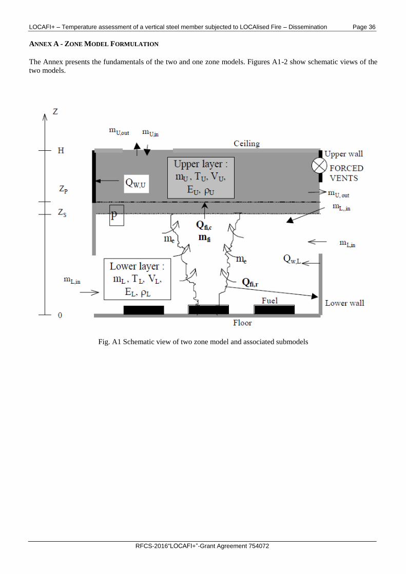
ANNEX A - ZONE MODEL FORMULATION
The Annex presents the fundamentals of the two and one zone models. Figures A1-2 show schematic views of the
two models.
Fig. A1 Schematic view of two zone model and associated submodels
LOCAFI+ – Temperature assessment of a vertical steel member subjected to LOCAlised Fire – Dissemination Page 37
RFCS-2016“LOCAFI+”-Grant Agreement 754072
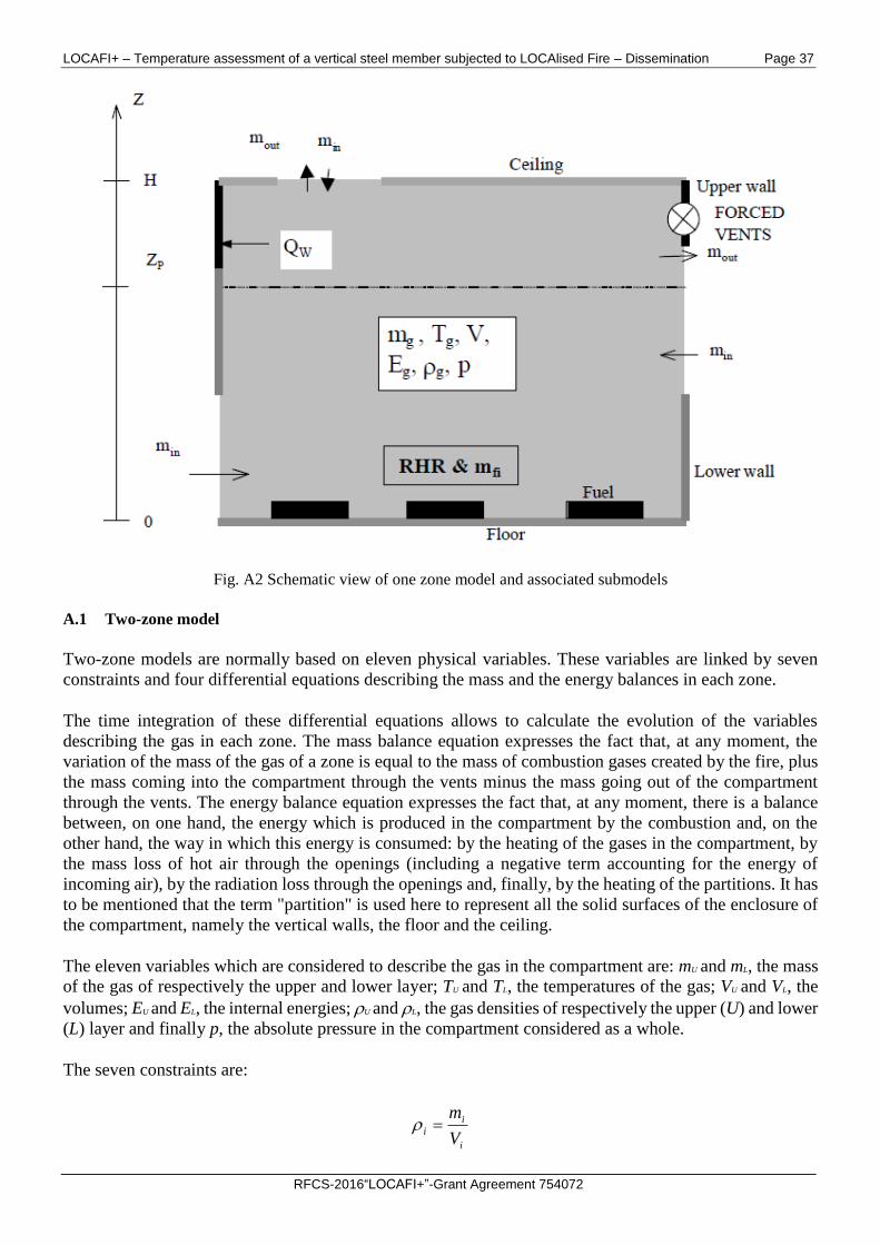
Fig. A2 Schematic view of one zone model and associated submodels
A.1 Two-zone model
Two-zone models are normally based on eleven physical variables. These variables are linked by seven
constraints and four differential equations describing the mass and the energy balances in each zone.
The time integration of these differential equations allows to calculate the evolution of the variables
describing the gas in each zone. The mass balance equation expresses the fact that, at any moment, the
variation of the mass of the gas of a zone is equal to the mass of combustion gases created by the fire, plus
the mass coming into the compartment through the vents minus the mass going out of the compartment
through the vents. The energy balance equation expresses the fact that, at any moment, there is a balance
between, on one hand, the energy which is produced in the compartment by the combustion and, on the
other hand, the way in which this energy is consumed: by the heating of the gases in the compartment, by
the mass loss of hot air through the openings (including a negative term accounting for the energy of
incoming air), by the radiation loss through the openings and, finally, by the heating of the partitions. It has
to be mentioned that the term "partition" is used here to represent all the solid surfaces of the enclosure of
the compartment, namely the vertical walls, the floor and the ceiling.
The eleven variables which are considered to describe the gas in the compartment are: mU and mL, the mass
of the gas of respectively the upper and lower layer; TU and TL, the temperatures of the gas; VU and VL, the
volumes; EU and EL, the internal energies; U and L, the gas densities of respectively the upper (U) and lower
(L) layer and finally p, the absolute pressure in the compartment considered as a whole.
The seven constraints are:
i
ii
V
m
LOCAFI+ – Temperature assessment of a vertical steel member subjected to LOCAlised Fire – Dissemination Page 38
RFCS-2016“LOCAFI+”-Grant Agreement 754072
iiVi TmTcE
iiRTp (A.1)
LU VVV
LUi ,
with: cV(T), the specific heat of the gas in the compartment;
R, the universal gas constant
i, equal U for upper layer & L for lower layer
The specific heat of the gas at constant volume and at constant pressure, the universal gas constant R and
the ratio of specific heat are related by:
ivip TcTcR
(A.2)
iv
ip
iTc
TcT
The variation of the specific heat of the gas with the temperature is taken into account by the following
relation:
kgKJTTcp 952187.0 (A.3)
This law is obtained by a linear regression on the point by point law given in the NFPE Handbook of Fire
Protection Engineering.
The mass balance equations have the general form of equations (A.4) and (A.5) in which a doted variable
x& means the derivative of x with respect to time. Equations (A.4) et (A.5) states that the variation of
gaseous mass in each zones is made of the mass exchanges of one zone with the fire, with the other zone,
and with the external world through the different vent types (see Annex B).
fieUFVoutUFVinUHVoutUHVinUVVoutU mmmmmmmm (A.4)
eLFVoutLFVinLHVoutLHVinLVVoutLVVinUVVinL mmmmmmmmm (A.5)
The energy balance equations have the general form of equations (A6) and (A7) stating that the variation
of energy in each zones is made of the energy exchanges of one zone with the fire, with the other zone,
with the surrounding partitions and with the external world trough vents.
RHRTmTcqqqqqqqq LentLpUFVoutUFVinUHVoutUHVinUVVoutUwallUradU 7.0 (A.6)
entLFVoutLFVinLHVoutLHVinLVVoutLVVinUVVinLwallLradL qqqqqqqqqqq (A.7)
LOCAFI+ – Temperature assessment of a vertical steel member subjected to LOCAlised Fire – Dissemination Page 39
RFCS-2016“LOCAFI+”-Grant Agreement 754072
In these balances, mass or energy rate corresponding to a decrease of mass or energy in the compartment
are negatives.
Four basic variables have to be chosen to describe the system. Provided that the zones temperatures TU and
TL, the altitude of separation of zones ZS and the difference of pressure from the initial time p are chosen,
equations (A.4) to (A.7) can be transformed in the system of ordinary differential equations (ODE) formed
by equations (A.8) to (A.11). [FORNEY 1994]:
V
qp
1
(A.8)
pVTmTcqVTc
T UUUUpU
UUUp
U
1 (A.9)
pVTmTcqVTc
T LLLLpL
LLLp
L
1 (A.10)
pVqTPAT
Z LL
fL
S 11
(A.11)
A.2 One-zone model
In case of a one zone model, the number of variables which is reduce to six, describing the gas in the
compartment as a whole. i.e. mg, the mass of the gas; Tg, the temperature of the gas; V, the volume of the
compartment (constant); Eg, the internal energy; p, the pressure in the compartment; g, the gas density.
The number of constraints is reduced to 4:
V
mg
g
gggVg TmTcE
gg RTp (A.12)
constV
The mass balance is expressed now by equation (A.13):
fiouting mmmm (A.13)
And the energy balance is expressed by equation (A.14):
RHRTmTcTmTcqqq outinoutpgoutgpwallradU (A.14)
In these balances, mass or energy rate corresponding to a decrease of mass or energy in the compartment
are negatives.
LOCAFI+ – Temperature assessment of a vertical steel member subjected to LOCAlised Fire – Dissemination Page 40
RFCS-2016“LOCAFI+”-Grant Agreement 754072
Four basic variables have to be chosen to describe the system. Provided that the zone temperature T and the
difference of pressure from the initial time p are chosen, equations (A.13) and (A.14) can be transformed
in the system of ordinary differential equations formed by equations (A.15) and (A.16).
V
qp
1
(A.15)
pVTmTcqVTc
T gggp
ggp
g
1 (A.16)
A.3 Time integration
As mentioned, the systems of equations (A.8) to (A.11) (2ZM) and of equations (A.15) and (A.16) (1ZM)
are to be solved to know the gas characteristics of zones at each time. These systems of ODE are stiff. A
physical, although not rigorous from a mathematical point of view, interpretation of stiffness is that the
time constant relative to the pressure variation is much shorter than the time constant of the temperature
variation. It is therefore usual to rely on a specialised library solver specifically written for this kind of
problem. In the code OZone, the solver DEBDF is used.
A.4 Partition model
Usually the partition models of zone model are based on finite difference. This method does not allow to
solve the equation implicitly and therefor to fully couple the zone and the partition models. This problem
can be solved model by using the finite element method and by modifying the usual finite element
formulation. To fully respect the energy balance in case of one zone model, partitions have to be modelled
by one dimensional finite elements and in case of two zone model have to be modelled by two dimensional
finite elements because vertical fluxes exist in vertical partitions.
Even if OZone includes a two zone and a one zone, a one dimension partition model has been included.
Some preliminary work on two zone model with a two dimensional partition model has been made and has
shown that the partition model based on one dimension finite elements is a good approximation of the one
based on two dimension. In most cases, the two-dimensional phenomena are negligible. The increases of
the computing time and of the difficulties to define the compartment are quite big and are useless in most
cases.
Partitions can be divided in three types: the upper horizontal partition, the ceiling; the lower horizontal
partition, the floor; and, finally, the walls. The basic finite element formulation is the same for the three
types of partitions but the boundary conditions are different.
A.4.1 Partition model formulation
A partition is discretised by a single dimension finite element model as depicted in Figure A3. With this
discretisation, the temperature is computed at the interface between the different layers, or elements, and
the hypothesis is made of a linear temperature variation on the thickness of each layer.
LOCAFI+ – Temperature assessment of a vertical steel member subjected to LOCAlised Fire – Dissemination Page 41
RFCS-2016“LOCAFI+”-Grant Agreement 754072
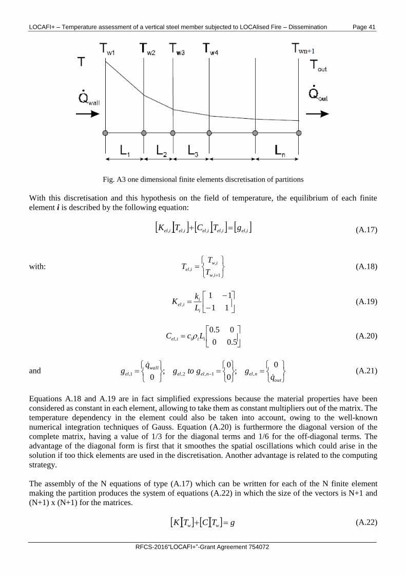
Fig. A3 one dimensional finite elements discretisation of partitions
With this discretisation and this hypothesis on the field of temperature, the equilibrium of each finite
element i is described by the following equation:
ielielielieliel gTCTK ,,,,, (A.17)
with:
1,
,
,
iw
iw
ielT
TT (A.18)
11
11,
i
iiel
L
kK (A.19)
5.00
05.0, iiiiel LcC (A.20)
and
out
nelnelel
wall
elq
ggtogq
g
0;
0
0;
0,1,2,1, (A.21)
Equations A.18 and A.19 are in fact simplified expressions because the material properties have been
considered as constant in each element, allowing to take them as constant multipliers out of the matrix. The
temperature dependency in the element could also be taken into account, owing to the well-known
numerical integration techniques of Gauss. Equation (A.20) is furthermore the diagonal version of the
complete matrix, having a value of 1/3 for the diagonal terms and 1/6 for the off-diagonal terms. The
advantage of the diagonal form is first that it smoothes the spatial oscillations which could arise in the
solution if too thick elements are used in the discretisation. Another advantage is related to the computing
strategy.
The assembly of the N equations of type (A.17) which can be written for each of the N finite element
making the partition produces the system of equations (A.22) in which the size of the vectors is N+1 and
(N+1) x (N+1) for the matrices.
gTCTK ww (A.22)
LOCAFI+ – Temperature assessment of a vertical steel member subjected to LOCAlised Fire – Dissemination Page 42
RFCS-2016“LOCAFI+”-Grant Agreement 754072
out
wall
q
q
g
0
0
(A.23)
The energy transmitted at the partition interface results from heat transfer by convection and radiation
between zones and the partition and between the fire and the partition. The energy transmitted at the
interface between the outside world and the partition is due to heat transfer by convection and radiation.
We note Tw1 the inside partition surface temperature and Tw,n+1 the outside partition surface temperature. Tz
is the gas temperature of the zone in contact with the partition inside surface, i.e. Tz = TU or TL in case of
2ZM or Tz = Tg in case of 1ZM.
From the system of equations (A.22), it is very easy to obtain the system of equations (A.24), efficiently
computed due to the diagonal nature of C.
ww TKgCT 1
(A.24)
This system of equations is a set of N differential equations for the N temperatures of the partition. The
temperature of the compartment is only present in the first term of the load vector. It has a similar form as
the system of equations (A.8) to (A.11) (2ZM) and of equations (A.15) and (A.16) (1ZM) established for
the variables of the gas zones and could be written in the following way.
2,1,11, ,, www TTTgT , 3,2,1,22, ,, wwww TTTgT , outNwNwNNw TTTgT ,, 1,,1, (A.25)
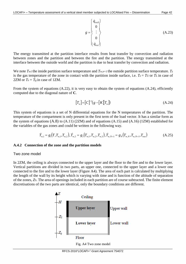
A.4.2 Connection of the zone and the partition models
Two zone model
In 2ZM, the ceiling is always connected to the upper layer and the floor to the fire and to the lower layer.
Vertical partitions are divided in two parts, an upper one, connected to the upper layer and a lower one
connected to the fire and to the lower layer (Figure A4). The area of each part is calculated by multiplying
the length of the wall by its height which is varying with time and is function of the altitude of separation
of the zones, ZS. The area of openings included in each partition are of course subtracted. The finite element
discretisations of the two parts are identical, only the boundary conditions are different.
Fig. A4 Two zone model
LOCAFI+ – Temperature assessment of a vertical steel member subjected to LOCAlised Fire – Dissemination Page 43
RFCS-2016“LOCAFI+”-Grant Agreement 754072
The system of equations (A.24) has to be built once for the ceiling and once for the floor. If the enclosure
has M different types of walls, it has to be build 2M times. If Neq,c and Neq,f the number of node of the ceiling
and of the floor, and Neq,i the number of node of the wall n°i, the total set of partition equations contains
Neq,w differential equations, given by equation (A.26).
M
i
ieqceqfeqweq NNNN1
,,,, 2 (A.26)
Equations (A.8) to (A.11) and equations (A.24) form a set of Neq,w+4 differential equations which can be
passed on to the numerical solver. This one will integrate the equations taking into account the coupling
between the compartment and the partition and solving the Neq,w+4 variables which are the pressure
variation, the temperature in the upper zone, the temperature in the upper zone and the altitude of the zone
interface, plus the temperatures at each node of the partitions.
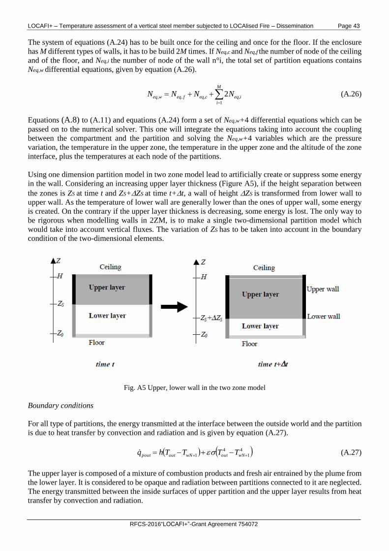
Using one dimension partition model in two zone model lead to artificially create or suppress some energy
in the wall. Considering an increasing upper layer thickness (Figure A5), if the height separation between
the zones is ZS at time t and ZS+ZS at time t+t, a wall of height ZS is transformed from lower wall to
upper wall. As the temperature of lower wall are generally lower than the ones of upper wall, some energy
is created. On the contrary if the upper layer thickness is decreasing, some energy is lost. The only way to
be rigorous when modelling walls in 2ZM, is to make a single two-dimensional partition model which
would take into account vertical fluxes. The variation of ZS has to be taken into account in the boundary
condition of the two-dimensional elements.
Fig. A5 Upper, lower wall in the two zone model
Boundary conditions
For all type of partitions, the energy transmitted at the interface between the outside world and the partition
is due to heat transfer by convection and radiation and is given by equation (A.27).
4
1
4
1 wNoutwNoutpout TTTThq (A.27)
The upper layer is composed of a mixture of combustion products and fresh air entrained by the plume from
the lower layer. It is considered to be opaque and radiation between partitions connected to it are neglected.
The energy transmitted between the inside surfaces of upper partition and the upper layer results from heat
transfer by convection and radiation.
LOCAFI+ – Temperature assessment of a vertical steel member subjected to LOCAlised Fire – Dissemination Page 44
RFCS-2016“LOCAFI+”-Grant Agreement 754072
4
1
4
1, wUwUUwall TTTThq (A.28)
The lower layer is composed essentially of fresh air with only few combustion products, so its relative
emissivity is considered to be nil. The energy transmitted between the inside surfaces of lower partitions
and the lower layer results only from heat transfer by convection. The radiation from the fire is represented
by the qfi,w term.
wfiwLLwall qTThq ,1, (A.29)
qfi,w [W/m²] is obtained by dividing 30% of the rate of heat release by the total area of the lower partition,
including the opening area.
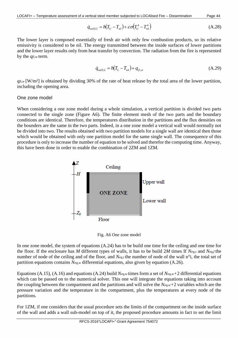
One zone model
When considering a one zone model during a whole simulation, a vertical partition is divided two parts
connected to the single zone (Figure A6). The finite element mesh of the two parts and the boundary
conditions are identical. Therefore, the temperatures distribution in the partitions and the flux densities on
the bounders are the same in the two parts. Indeed, in a one zone model a vertical wall would normally not
be divided into two. The results obtained with two partition models for a single wall are identical then those
which would be obtained with only one partition model for the same single wall. The consequence of this
procedure is only to increase the number of equation to be solved and therefor the computing time. Anyway,
this have been done in order to enable the combination of 2ZM and 1ZM.
Fig. A6 One zone model
In one zone model, the system of equations (A.24) has to be build one time for the ceiling and one time for
the floor. If the enclosure has M different types of walls, it has to be build 2M times If Neq,c and Neq,f the
number of node of the ceiling and of the floor, and Neq,i the number of node of the wall n°i, the total set of
partition equations contains Neq,w differential equations, also given by equation (A.26).
Equations (A.15), (A.16) and equations (A.24) build Neq,w times form a set of Neq,w+2 differential equations
which can be passed on to the numerical solver. This one will integrate the equations taking into account
the coupling between the compartment and the partitions and will solve the Neq,w+2 variables which are the
pressure variation and the temperature in the compartment, plus the temperatures at every node of the
partitions.
For 1ZM, if one considers that the usual procedure sets the limits of the compartment on the inside surface
of the wall and adds a wall sub-model on top of it, the proposed procedure amounts in fact to set the limit
LOCAFI+ – Temperature assessment of a vertical steel member subjected to LOCAlised Fire – Dissemination Page 45
RFCS-2016“LOCAFI+”-Grant Agreement 754072
of the compartment on the outside surface of the wall. Because all the equations are solved simultaneously
with an implicit procedure, the energy balance between the gas and the wall is totally respected.
Boundary conditions
For the three types of partitions, the energy transmitted at the interface between the outside world and the
partition is due to heat transfer by convection and radiation and is given by equation (A.30).
4
1
4
1 wNoutwNoutpout TTTThq (A.30)
The energy transmitted at the inside partition interfaces results from heat transfer by convection and
radiation between the zone and the partitions.
4
1
4
1 wgwgwall TTTThq (A.31)
A.5 Switch from two zones to one zone model
If some criteria are encountered during a two zone simulation, the code will automatically switch to a one
zone simulation, which suits better to the situation inside the compartment at this moment. The simulation
will continue to the end of the fire considering a one zone model. The criteria of switch will be explained
in Annex F. The aim of this paragraph is to set how OZone deals with the basic variables of the zone
models, how it sets the one zone initial conditions and how it deals with partitions models.
Zone models formulation
The time at which the switch from the 2ZM to the 1ZM happens is ts. The values of the eleven basic
variables describing the gas in the two zones are known until ts thanks to the time integration of equations
(A.8) to (A.11) and considering the constraints (A.1). To continue the simulation with a one zone model,
it is possible to begin to solve the equations (A.15) and (A.16) associated to initial conditions representing
the situation at that time. The point is to set the 1ZM initial values (at time ts).
In one zone model, there are six variables describing the gas in the compartment as a whole, linked by four
constraints. Two new constraints are needed to fix the new initial conditions.
One obtains these two additional condition by setting that during the transition from 2 zones to 1 zone, the
total mass of gas and the total energy in the compartment are conserved.
sLsUsg tmtmtm (A.32)
sLsUsg tEtEtE (A.33)
The initial (at time ts) one zone temperature Tg(ts) and one zone pressure p(ts) can be deduce from equations
(A.32), (A.33) and (A.12).
Afterward, the one zone model runs with its associated sub-models for calculating exchanges of energy and
mass through the vents. The partition models formulation and their initial values are explained in Annex F.
Wall model formulation
The partition temperatures at time ts are obtained by integrating the set of equations (A.24) coupled to the
2 zone basic equations (A.8) to (A.11). At this time, the height of the lower and upper walls (vertical
LOCAFI+ – Temperature assessment of a vertical steel member subjected to LOCAlised Fire – Dissemination Page 46
RFCS-2016“LOCAFI+”-Grant Agreement 754072
partitions) are respectively ZS(ts) and H-ZS(ts). From the time of transition ts to the end of the calculation
the one zone model is linked to the lower and upper walls which keep the dimension they had at time ts, i.e.
Zs(ts) and H-ZS(ts). During the transition, no modification of partition temperatures of wall dimension is
made, only the boundary conditions are modified. This way to proceed enables to fully respect the
conservation of energy during the transition from the two zones to the one zone model.
If a one zone model simulation is set from the beginning of the calculation, the dimension of the lower and
upper walls are the initial dimensions, deduced from the initial altitude of separation of zones, until the end
of the calculations.
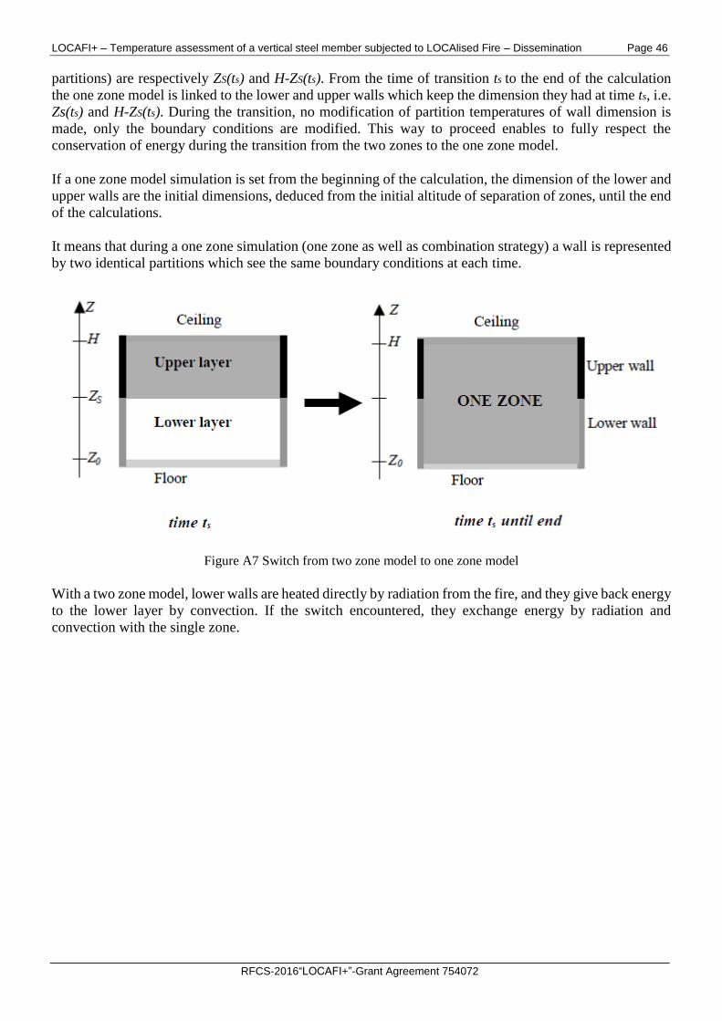
It means that during a one zone simulation (one zone as well as combination strategy) a wall is represented
by two identical partitions which see the same boundary conditions at each time.
Figure A7 Switch from two zone model to one zone model
With a two zone model, lower walls are heated directly by radiation from the fire, and they give back energy
to the lower layer by convection. If the switch encountered, they exchange energy by radiation and
convection with the single zone.
LOCAFI+ – Temperature assessment of a vertical steel member subjected to LOCAlised Fire – Dissemination Page 47
RFCS-2016“LOCAFI+”-Grant Agreement 754072
ANNEX B - EXCHANGE THROUGH VENTS
Three types of vent models have been introduced in OZone: vertical vents, horizontal vents and forced vents.
B.1 Vertical vents (in walls)
B.1.1 Convective exchanges
The mass flow through vents is calculated by integrating the Bernoulli’s law on each openings.
2
2
1vp (B.1)
Z
Z A
BA
A
AVV dz
zP
zPRT
RT
zPtorTKbm 12,,
(B.2)
with: subscript A: variable at origin of the flux;
subscript B: variable at destination of the flux;
Z' and Z": bounds of integration on altitude Z;
b: width of vertical vent;
α: U if the integration is made in the upper layer, L if the integration is made in the lower layer and g in
case of one zone model;
β: in if gas goes into the compartment, out if gas goes out of the compartment
If the altitude where the pressure inside the compartment is equal to the pressure outside of the compartment is in a
vertical vent, the vertical vents is divided in two parts, one where the mass flow goes inside the compartment and
another one where the mass flow goes outside. This altitude is called the neutral plane altitude. Moreover in a two
zone model, if the altitude of separation between the zones is in the opening, another subdivision in two encountered.
In 1ZM (One Zone Model), three possibilities exist following the neutral level position. In 2ZM (Two Zones Model),
10 possibilities exist following the neutral level and the zone separation altitude positions. For each vertical vent,
equation A1 is the solved 1 or 3 times with the appropriate bounds of integration on the altitude (Z' and Z" can be
the sill of the vent, the soffit of the vent, the neutral plane altitude or the separation between the zone altitude).
Figure B1 shows in case of 2ZM and 1ZM one possible situation of relative position of Zsill, ZP, ZS and Zsoffit.
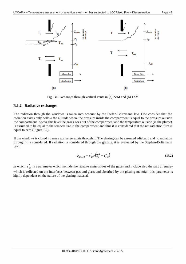
LOCAFI+ – Temperature assessment of a vertical steel member subjected to LOCAlised Fire – Dissemination Page 48
RFCS-2016“LOCAFI+”-Grant Agreement 754072
Fig. B1 Exchanges through vertical vents in (a) 2ZM and (b) 1ZM
B.1.2 Radiative exchanges
The radiation through the windows is taken into account by the Stefan-Boltzmann law. One consider that the
radiation exists only bellow the altitude where the pressure inside the compartment is equal to the pressure outside
the compartment. Above this level the gases goes out of the compartment and the temperature outside (in the plume)
is assumed to be equal to the temperature in the compartment and thus it is considered that the net radiation flux is
equal to zero (Figure B2).
If the windows is closed no mass exchange exists through it. The glazing can be assumed adiabatic and no radiation
through it is considered. If radiation is considered through the glazing, it is evaluated by the Stephan-Boltzmann
law:
44*
, outZglradgl TTq (B.2)
in which *
gl is a parameter which include the relative emissivities of the gazes and include also the part of energy
which is reflected on the interfaces between gas and glass and absorbed by the glazing material; this parameter is
highly dependent on the nature of the glazing material.
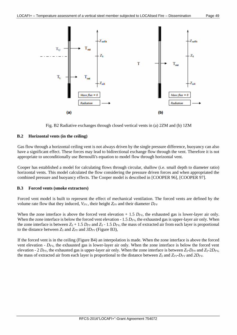
LOCAFI+ – Temperature assessment of a vertical steel member subjected to LOCAlised Fire – Dissemination Page 49
RFCS-2016“LOCAFI+”-Grant Agreement 754072
Fig. B2 Radiative exchanges through closed vertical vents in (a) 2ZM and (b) 1ZM
B.2 Horizontal vents (in the ceiling)
Gas flow through a horizontal ceiling vent is not always driven by the single pressure difference, buoyancy can also
have a significant effect. These forces may lead to bidirectional exchange flow through the vent. Therefore it is not
appropriate to unconditionally use Bernoulli's equation to model flow through horizontal vent.
Cooper has established a model for calculating flows through circular, shallow (i.e. small depth to diameter ratio)
horizontal vents. This model calculated the flow considering the pressure driven forces and when appropriated the
combined pressure and buoyancy effects. The Cooper model is described in [COOPER 96], [COOPER 97].
B.3 Forced vents (smoke extractors)
Forced vent model is built to represent the effect of mechanical ventilation. The forced vents are defined by the
volume rate flow that they induced, VFV , their height ZFV and their diameter DFV
When the zone interface is above the forced vent elevation + 1.5 DFV, the exhausted gas is lower-layer air only.
When the zone interface is below the forced vent elevation - 1.5 DFV, the exhausted gas is upper-layer air only. When
the zone interface is between ZS + 1.5 DFV and ZS - 1.5 DFV, the mass of extracted air from each layer is proportional
to the distance between ZS and ZFV and 3DFV (Figure B3),
If the forced vent is in the ceiling (Figure B4) an interpolation is made. When the zone interface is above the forced
vent elevation - DFV, the exhausted gas is lower-layer air only. When the zone interface is below the forced vent
elevation - 2 DFV, the exhausted gas is upper-layer air only. When the zone interface is between ZS-DFV and ZS-2DFV,
the mass of extracted air from each layer is proportional to the distance between ZS and ZFV-DFV and 2DFV.
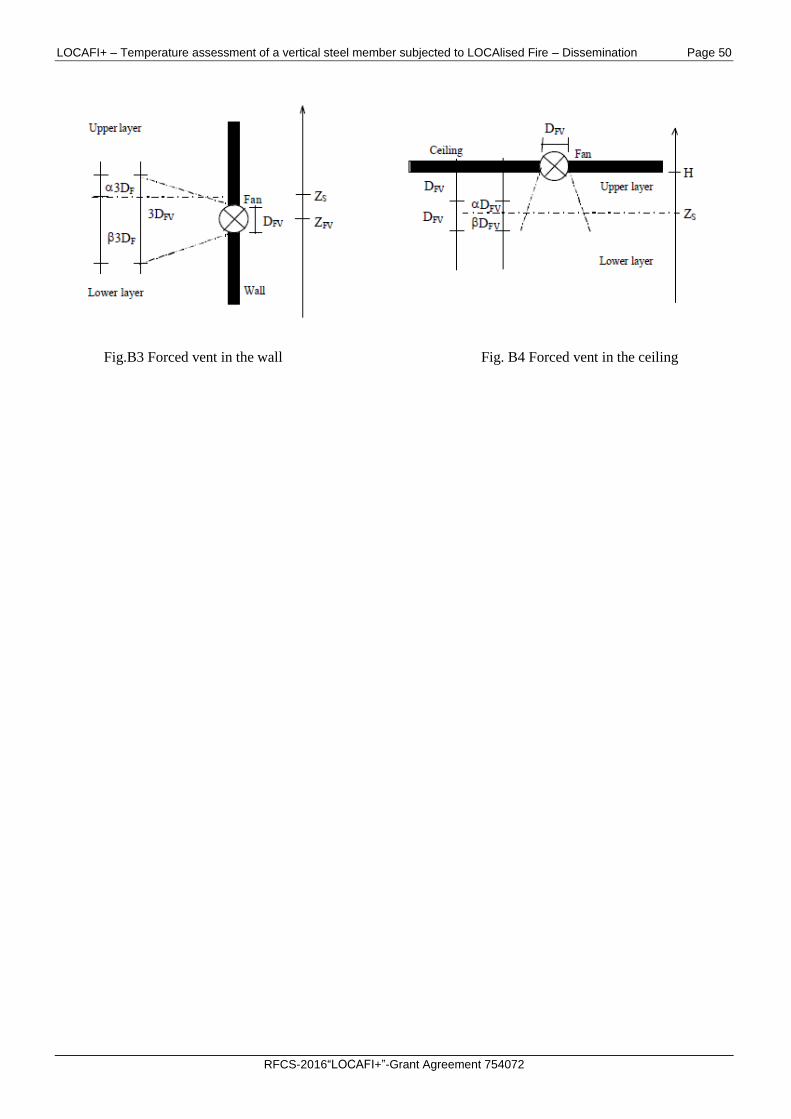
LOCAFI+ – Temperature assessment of a vertical steel member subjected to LOCAlised Fire – Dissemination Page 50
RFCS-2016“LOCAFI+”-Grant Agreement 754072
Fig.B3 Forced vent in the wall Fig. B4 Forced vent in the ceiling
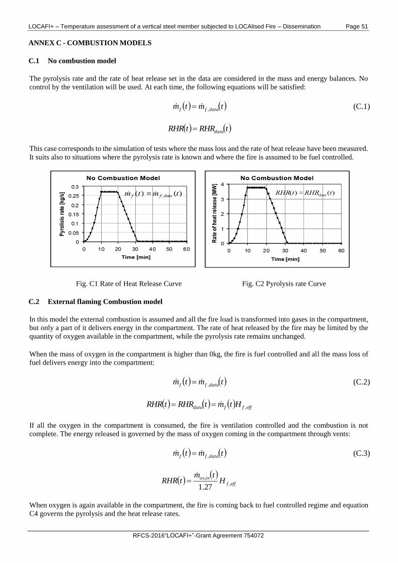
LOCAFI+ – Temperature assessment of a vertical steel member subjected to LOCAlised Fire – Dissemination Page 51
RFCS-2016“LOCAFI+”-Grant Agreement 754072
ANNEX C - COMBUSTION MODELS
C.1 No combustion model
The pyrolysis rate and the rate of heat release set in the data are considered in the mass and energy balances. No
control by the ventilation will be used. At each time, the following equations will be satisfied:
tmtm dataff , (C.1)
tRHRtRHR data
This case corresponds to the simulation of tests where the mass loss and the rate of heat release have been measured.
It suits also to situations where the pyrolysis rate is known and where the fire is assumed to be fuel controlled.
Fig. C1 Rate of Heat Release Curve Fig. C2 Pyrolysis rate Curve
C.2 External flaming Combustion model
In this model the external combustion is assumed and all the fire load is transformed into gases in the compartment,
but only a part of it delivers energy in the compartment. The rate of heat released by the fire may be limited by the
quantity of oxygen available in the compartment, while the pyrolysis rate remains unchanged.
When the mass of oxygen in the compartment is higher than 0kg, the fire is fuel controlled and all the mass loss of
fuel delivers energy into the compartment:
tmtm dataff , (C.2)
effffdata HtmtRHRtRHR ,
If all the oxygen in the compartment is consumed, the fire is ventilation controlled and the combustion is not
complete. The energy released is governed by the mass of oxygen coming in the compartment through vents:
tmtm dataff , (C.3)
efff
inoxH
tmtRHR ,
,
27.1
When oxygen is again available in the compartment, the fire is coming back to fuel controlled regime and equation
C4 governs the pyrolysis and the heat release rates.
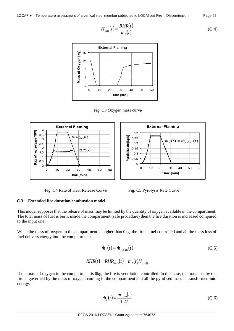
LOCAFI+ – Temperature assessment of a vertical steel member subjected to LOCAlised Fire – Dissemination Page 52
RFCS-2016“LOCAFI+”-Grant Agreement 754072
tm
tRHRtH
fi
ceff (C.4)
Fig. C3 Oxygen mass curve
Fig. C4 Rate of Heat Release Curve Fig. C5 Pyrolysis Rate Curve
C.3 Extended fire duration combustion model
This model supposes that the release of mass may be limited by the quantity of oxygen available in the compartment.
The total mass of fuel is burnt inside the compartment (safe procedure) then the fire duration is increased compared
to the input one.
When the mass of oxygen in the compartment is higher than 0kg, the fire is fuel controlled and all the mass loss of
fuel delivers energy into the compartment:
tmtm dataff , (C.5)
effffdata HtmtRHRtRHR ,
If the mass of oxygen in the compartment is 0kg, the fire is ventilation controlled. In this case, the mass lost by the
fire is governed by the mass of oxygen coming in the compartment and all the pyrolised mass is transformed into
energy:
27.1
, tmtm inox
f
(C.6)
External Flaming
0
4
8
12
16
0 10 20 30 40 50 60
Time [min]
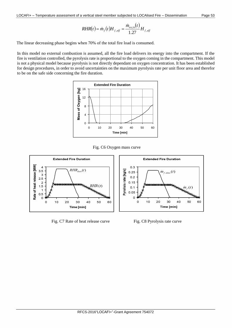
LOCAFI+ – Temperature assessment of a vertical steel member subjected to LOCAlised Fire – Dissemination Page 53
RFCS-2016“LOCAFI+”-Grant Agreement 754072
efff
inox
effff Htm
HtmtRHR ,
,
,27.1
The linear decreasing phase begins when 70% of the total fire load is consumed.
In this model no external combustion is assumed, all the fire load delivers its energy into the compartment. If the
fire is ventilation controlled, the pyrolysis rate is proportional to the oxygen coming in the compartment. This model
is not a physical model because pyrolysis is not directly dependant on oxygen concentration. It has been established
for design procedures, in order to avoid uncertainties on the maximum pyrolysis rate per unit floor area and therefor
to be on the safe side concerning the fire duration.
Fig. C6 Oxygen mass curve
Fig. C7 Rate of heat release curve Fig. C8 Pyrolysis rate curve
Extended Fire Duration
0
4
8
12
16
0 10 20 30 40 50 60
Time [min]
LOCAFI+ – Temperature assessment of a vertical steel member subjected to LOCAlised Fire – Dissemination Page 54
RFCS-2016“LOCAFI+”-Grant Agreement 754072
ANNEX D - NATIONAL ANNEXES AND NATIONAL PARAMETERS FOR THE APPLICATION OF THE
NATURAL FIRE IN DIFFERENT EUROPEAN COUNTRIES IN THE OZONE SOFTWARE
Several National Annexes of EN 1991-1-2 are introduced in OZone. By comparing the calculation method in
application in a country to the original one described in the Eurocodes, three different options have been observed:
- the values of the factors involved in the computation of the design fire load density as well as the calculation
procedure were changed;
- only the values involved in the computation of the design fire load density were changed;
- no changes in the calculation procedure or for the values of the factors involved in the computation of the
design fire load density.
It should also be noted that Denmark do not allow using Annex E of EN1991-1-2 but no other calculation method is
proposed in the Danish National Annex. This country is an exception.
OZone interface is available in English and French and the occupancies have been translated into the National
language(s) of the country.
The German National Annex presents a specific method where two separate partial safety factors are calculated. The
first one is applied to the fire load density (similar to EN) and the second one is applied to the Rate of Heat Release
(not considered in the EN). These factors are function of the probability of occurrence of a damaging fire and the
permitted probability of failure. A probabilistic equation is used to evaluate these two factors.
In the Netherlands, the method is quite similar to the German one. However, it should be noted that the two partial
safety factors applied to the fire load density and the Rate of Heat Release are identical.
In UK, some formulae slightly differ but the method is the same as the Eurocode one.
A large number of countries follow the same calculation method as the one described in the EN 1991-1-2 but the
values of several parameters are different. For example:
- Germany and France are using a 90% fractile (instead of 80%), fire load densities are consequently different;
- Some countries have chosen to consider different fire load densities for several occupancies (independent of
the choice of fractile);
- France and Portugal have chosen to put all the delta factors accounting for active measures as equal to 1;
- Belgium, Spain and Italy are using other values for delta factors accounting for active measures.
A large number of countries have chosen to follow the Eurocode method without any modification of the values of
factors influencing the fire load density, like Czech Republic, Estonia, Hungary, Luxembourg, Poland, Romania,
Slovakia and Slovenia.
In the following the national parameters for the application of the Natural Fire in different European countries are
given.
Belgium
No changes in the calculation procedure were provided in the Belgium National Annex of EN1991-1-2.
For Table D1, the values for the factors taking into account the fire activation risk due to the size of the compartment
are replaced by a formula for areas between 25-2500m2. The descriptions of the occupancies are also extended.
In Table D2, some factors taking into account the different active firefighting measures are modified.
In Table D3, the hotel and hospital rooms are considered with the same fire load density and some supplementary
provisions are considered in case of localised fires.
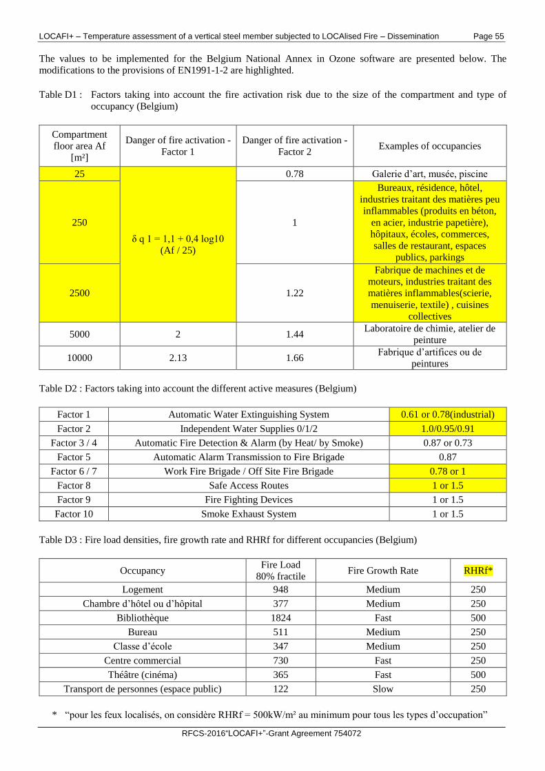
LOCAFI+ – Temperature assessment of a vertical steel member subjected to LOCAlised Fire – Dissemination Page 55
RFCS-2016“LOCAFI+”-Grant Agreement 754072
The values to be implemented for the Belgium National Annex in Ozone software are presented below. The
modifications to the provisions of EN1991-1-2 are highlighted.
Table D1 : Factors taking into account the fire activation risk due to the size of the compartment and type of
occupancy (Belgium)
Compartment
floor area Af
[m²]
Danger of fire activation -
Factor 1
Danger of fire activation -
Factor 2 Examples of occupancies
25
δ q 1 = 1,1 + 0,4 log10
(Af / 25)
0.78 Galerie d’art, musée, piscine
250 1
Bureaux, résidence, hôtel,
industries traitant des matières peu
inflammables (produits en béton,
en acier, industrie papetière),
hôpitaux, écoles, commerces,
salles de restaurant, espaces
publics, parkings
2500 1.22
Fabrique de machines et de
moteurs, industries traitant des
matières inflammables(scierie,
menuiserie, textile) , cuisines
collectives
5000 2 1.44 Laboratoire de chimie, atelier de
peinture
10000 2.13 1.66 Fabrique d’artifices ou de
peintures
Table D2 : Factors taking into account the different active measures (Belgium)
Factor 1 Automatic Water Extinguishing System 0.61 or 0.78(industrial)
Factor 2 Independent Water Supplies 0/1/2 1.0/0.95/0.91
Factor 3 / 4 Automatic Fire Detection & Alarm (by Heat/ by Smoke) 0.87 or 0.73
Factor 5 Automatic Alarm Transmission to Fire Brigade 0.87
Factor 6 / 7 Work Fire Brigade / Off Site Fire Brigade 0.78 or 1
Factor 8 Safe Access Routes 1 or 1.5
Factor 9 Fire Fighting Devices 1 or 1.5
Factor 10 Smoke Exhaust System 1 or 1.5
Table D3 : Fire load densities, fire growth rate and RHRf for different occupancies (Belgium)
Occupancy Fire Load
80% fractile Fire Growth Rate RHRf*
Logement 948 Medium 250
Chambre d’hôtel ou d’hôpital 377 Medium 250
Bibliothèque 1824 Fast 500
Bureau 511 Medium 250
Classe d’école 347 Medium 250
Centre commercial 730 Fast 250
Théâtre (cinéma) 365 Fast 500
Transport de personnes (espace public) 122 Slow 250
* “pour les feux localisés, on considère RHRf = 500kW/m² au minimum pour tous les types d’occupation”
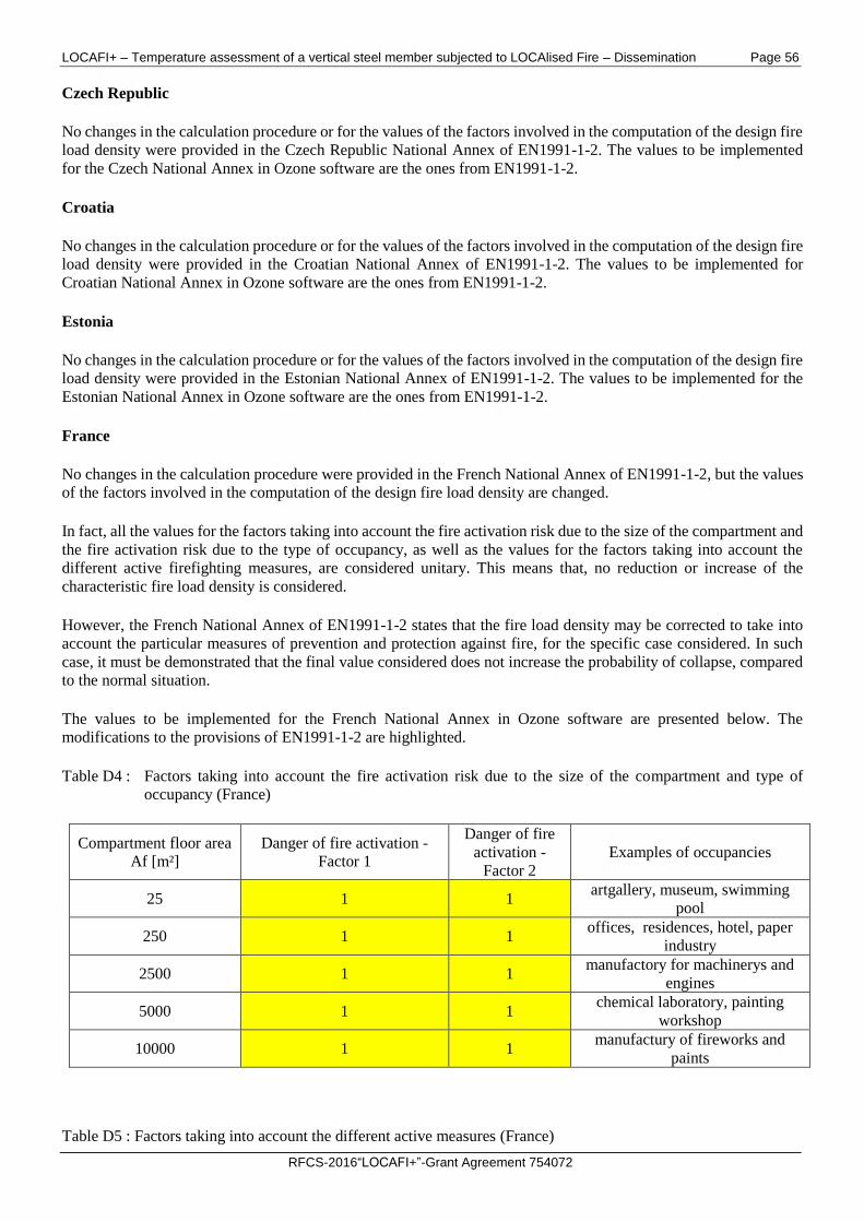
LOCAFI+ – Temperature assessment of a vertical steel member subjected to LOCAlised Fire – Dissemination Page 56
RFCS-2016“LOCAFI+”-Grant Agreement 754072
Czech Republic
No changes in the calculation procedure or for the values of the factors involved in the computation of the design fire
load density were provided in the Czech Republic National Annex of EN1991-1-2. The values to be implemented
for the Czech National Annex in Ozone software are the ones from EN1991-1-2.
Croatia
No changes in the calculation procedure or for the values of the factors involved in the computation of the design fire
load density were provided in the Croatian National Annex of EN1991-1-2. The values to be implemented for
Croatian National Annex in Ozone software are the ones from EN1991-1-2.
Estonia
No changes in the calculation procedure or for the values of the factors involved in the computation of the design fire
load density were provided in the Estonian National Annex of EN1991-1-2. The values to be implemented for the
Estonian National Annex in Ozone software are the ones from EN1991-1-2.
France
No changes in the calculation procedure were provided in the French National Annex of EN1991-1-2, but the values
of the factors involved in the computation of the design fire load density are changed.
In fact, all the values for the factors taking into account the fire activation risk due to the size of the compartment and
the fire activation risk due to the type of occupancy, as well as the values for the factors taking into account the
different active firefighting measures, are considered unitary. This means that, no reduction or increase of the
characteristic fire load density is considered.
However, the French National Annex of EN1991-1-2 states that the fire load density may be corrected to take into
account the particular measures of prevention and protection against fire, for the specific case considered. In such
case, it must be demonstrated that the final value considered does not increase the probability of collapse, compared
to the normal situation.
The values to be implemented for the French National Annex in Ozone software are presented below. The
modifications to the provisions of EN1991-1-2 are highlighted.
Table D4 : Factors taking into account the fire activation risk due to the size of the compartment and type of
occupancy (France)
Compartment floor area
Af [m²]
Danger of fire activation -
Factor 1
Danger of fire
activation -
Factor 2
Examples of occupancies
25 1 1 artgallery, museum, swimming
pool
250 1 1 offices, residences, hotel, paper
industry
2500 1 1 manufactory for machinerys and
engines
5000 1 1 chemical laboratory, painting
workshop
10000 1 1 manufactury of fireworks and
paints
Table D5 : Factors taking into account the different active measures (France)
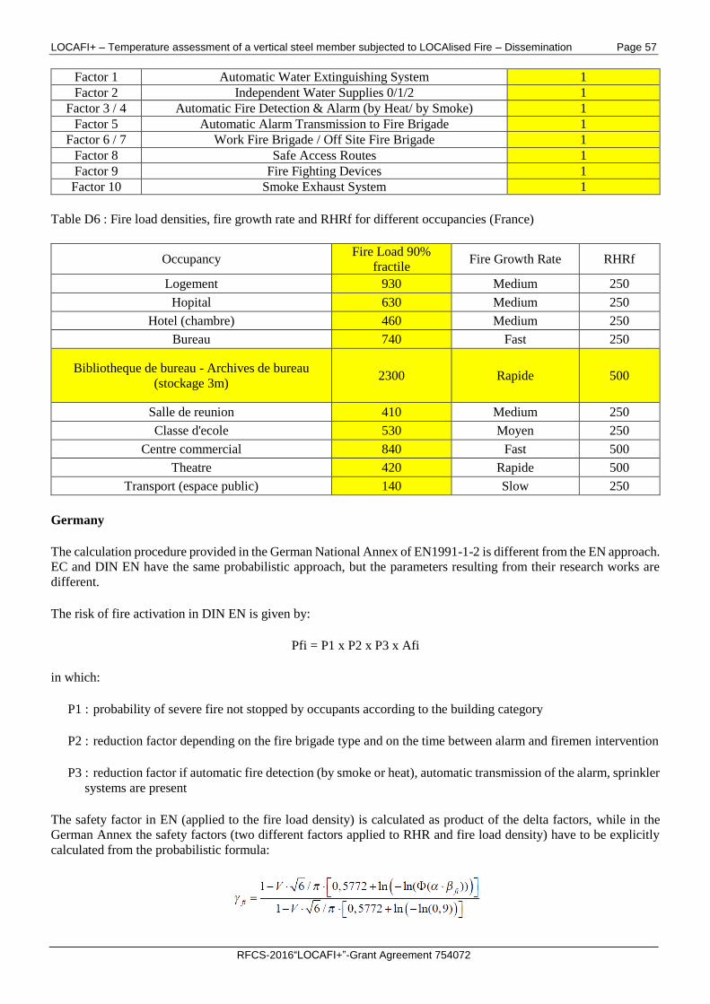
LOCAFI+ – Temperature assessment of a vertical steel member subjected to LOCAlised Fire – Dissemination Page 57
RFCS-2016“LOCAFI+”-Grant Agreement 754072
Factor 1 Automatic Water Extinguishing System 1
Factor 2 Independent Water Supplies 0/1/2 1
Factor 3 / 4 Automatic Fire Detection & Alarm (by Heat/ by Smoke) 1
Factor 5 Automatic Alarm Transmission to Fire Brigade 1
Factor 6 / 7 Work Fire Brigade / Off Site Fire Brigade 1
Factor 8 Safe Access Routes 1
Factor 9 Fire Fighting Devices 1
Factor 10 Smoke Exhaust System 1
Table D6 : Fire load densities, fire growth rate and RHRf for different occupancies (France)
Occupancy Fire Load 90%
fractile Fire Growth Rate RHRf
Logement 930 Medium 250
Hopital 630 Medium 250
Hotel (chambre) 460 Medium 250
Bureau 740 Fast 250
Bibliotheque de bureau - Archives de bureau
(stockage 3m) 2300 Rapide 500
Salle de reunion 410 Medium 250
Classe d'ecole 530 Moyen 250
Centre commercial 840 Fast 500
Theatre 420 Rapide 500
Transport (espace public) 140 Slow 250
Germany
The calculation procedure provided in the German National Annex of EN1991-1-2 is different from the EN approach.
EC and DIN EN have the same probabilistic approach, but the parameters resulting from their research works are
different.
The risk of fire activation in DIN EN is given by:
Pfi = P1 x P2 x P3 x Afi
in which:
P1 : probability of severe fire not stopped by occupants according to the building category
P2 : reduction factor depending on the fire brigade type and on the time between alarm and firemen intervention
P3 : reduction factor if automatic fire detection (by smoke or heat), automatic transmission of the alarm, sprinkler
systems are present
The safety factor in EN (applied to the fire load density) is calculated as product of the delta factors, while in the
German Annex the safety factors (two different factors applied to RHR and fire load density) have to be explicitly
calculated from the probabilistic formula:
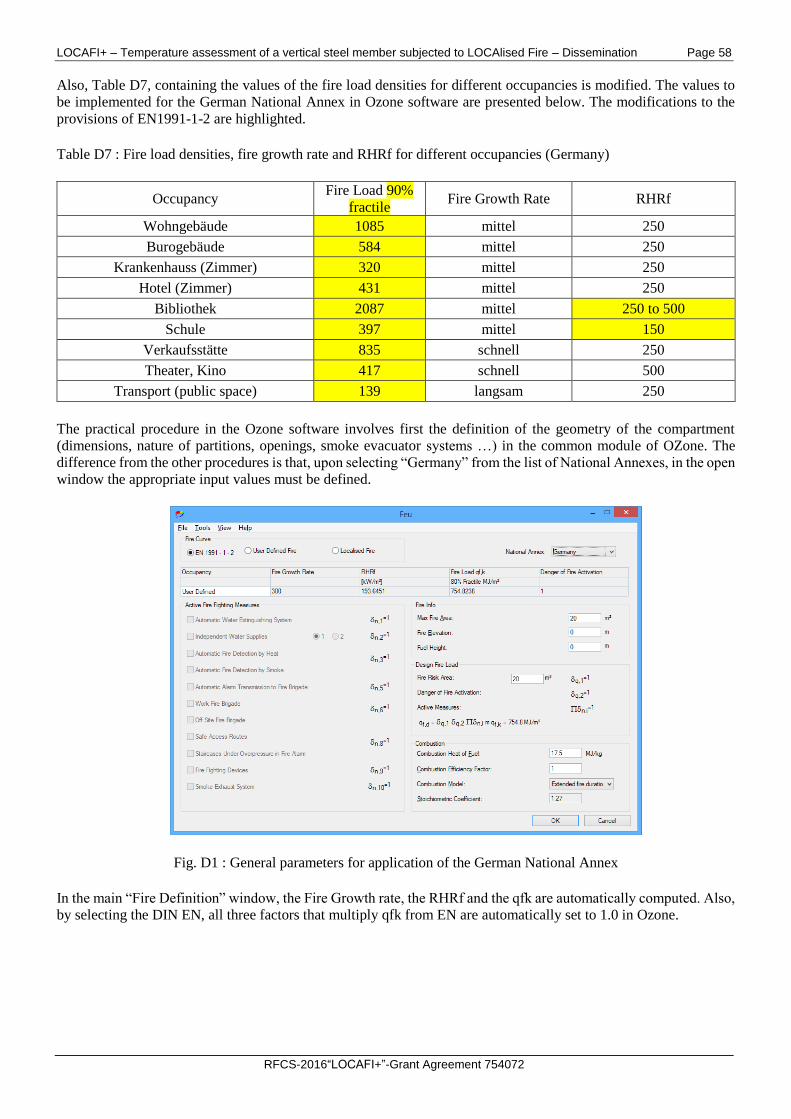
LOCAFI+ – Temperature assessment of a vertical steel member subjected to LOCAlised Fire – Dissemination Page 58
RFCS-2016“LOCAFI+”-Grant Agreement 754072
Also, Table D7, containing the values of the fire load densities for different occupancies is modified. The values to
be implemented for the German National Annex in Ozone software are presented below. The modifications to the
provisions of EN1991-1-2 are highlighted.
Table D7 : Fire load densities, fire growth rate and RHRf for different occupancies (Germany)
Occupancy Fire Load 90%
fractile Fire Growth Rate RHRf
Wohngebäude 1085 mittel 250
Burogebäude 584 mittel 250
Krankenhauss (Zimmer) 320 mittel 250
Hotel (Zimmer) 431 mittel 250
Bibliothek 2087 mittel 250 to 500
Schule 397 mittel 150
Verkaufsstätte 835 schnell 250
Theater, Kino 417 schnell 500
Transport (public space) 139 langsam 250
The practical procedure in the Ozone software involves first the definition of the geometry of the compartment
(dimensions, nature of partitions, openings, smoke evacuator systems …) in the common module of OZone. The
difference from the other procedures is that, upon selecting “Germany” from the list of National Annexes, in the open
window the appropriate input values must be defined.
Fig. D1 : General parameters for application of the German National Annex
In the main “Fire Definition” window, the Fire Growth rate, the RHRf and the qfk are automatically computed. Also,
by selecting the DIN EN, all three factors that multiply qfk from EN are automatically set to 1.0 in Ozone.
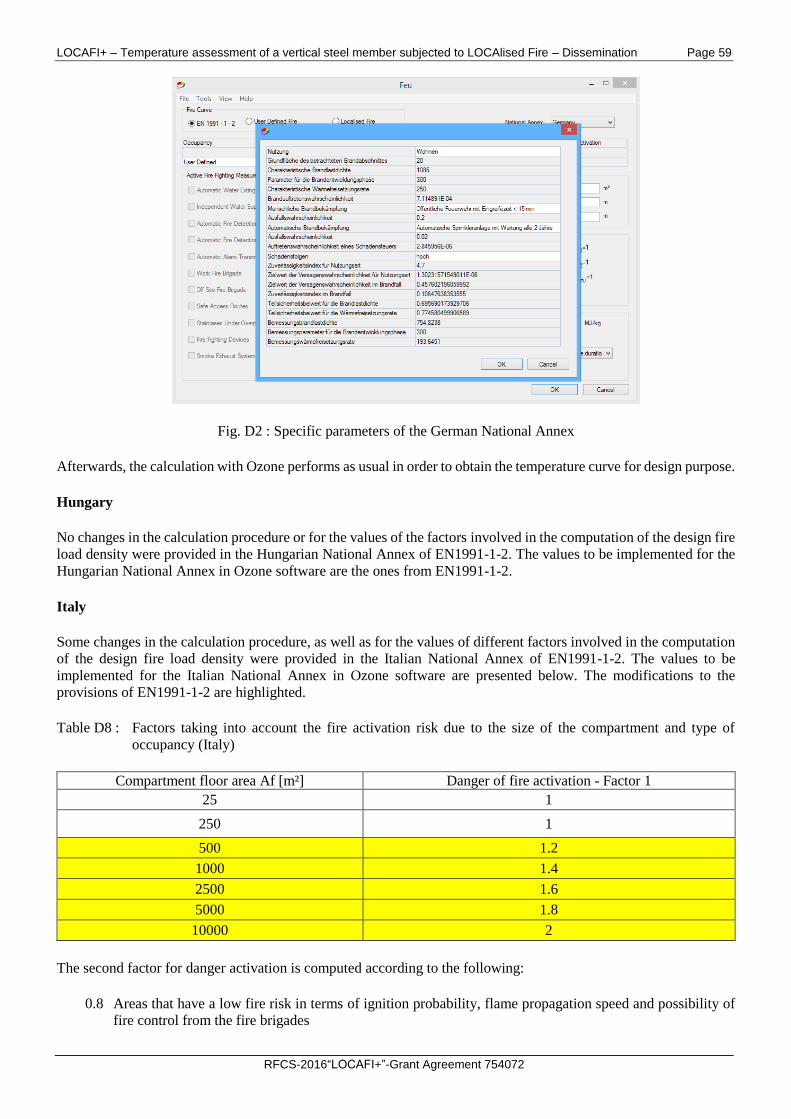
LOCAFI+ – Temperature assessment of a vertical steel member subjected to LOCAlised Fire – Dissemination Page 59
RFCS-2016“LOCAFI+”-Grant Agreement 754072
Fig. D2 : Specific parameters of the German National Annex
Afterwards, the calculation with Ozone performs as usual in order to obtain the temperature curve for design purpose.
Hungary
No changes in the calculation procedure or for the values of the factors involved in the computation of the design fire
load density were provided in the Hungarian National Annex of EN1991-1-2. The values to be implemented for the
Hungarian National Annex in Ozone software are the ones from EN1991-1-2.
Italy
Some changes in the calculation procedure, as well as for the values of different factors involved in the computation
of the design fire load density were provided in the Italian National Annex of EN1991-1-2. The values to be
implemented for the Italian National Annex in Ozone software are presented below. The modifications to the
provisions of EN1991-1-2 are highlighted.
Table D8 : Factors taking into account the fire activation risk due to the size of the compartment and type of
occupancy (Italy)
Compartment floor area Af [m²] Danger of fire activation - Factor 1
25 1
250 1
500 1.2
1000 1.4
2500 1.6
5000 1.8
10000 2
The second factor for danger activation is computed according to the following:
0.8 Areas that have a low fire risk in terms of ignition probability, flame propagation speed and possibility of
fire control from the fire brigades
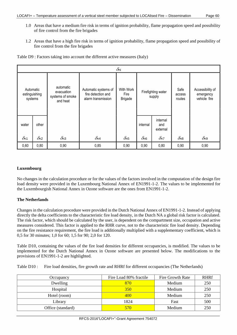
LOCAFI+ – Temperature assessment of a vertical steel member subjected to LOCAlised Fire – Dissemination Page 60
RFCS-2016“LOCAFI+”-Grant Agreement 754072
1.0 Areas that have a medium fire risk in terms of ignition probability, flame propagation speed and possibility
of fire control from the fire brigades
1.2 Areas that have a high fire risk in terms of ignition probability, flame propagation speed and possibility of
fire control from the fire brigades
Table D9 : Factors taking into account the different active measures (Italy)
ni
Automatic estinguishing
systems
automatic evacuation
systems of smoke and heat
Automatic systems of fire detection and
alarm transmission
With Work Fire
Brigade
Firefighting water supply
Safe access routes
Accessibility of emergency vehicle fire
water other internal internal
and external
n1 n2 n3 n4 n5 n6 n7 n8 n9
0,60 0,80 0,90 0,85 0,90 0,90 0,80 0,90 0,90
Luxembourg
No changes in the calculation procedure or for the values of the factors involved in the computation of the design fire
load density were provided in the Luxembourg National Annex of EN1991-1-2. The values to be implemented for
the Luxembourgish National Annex in Ozone software are the ones from EN1991-1-2.
The Netherlands
Changes in the calculation procedure were provided in the Dutch National Annex of EN1991-1-2. Instead of applying
directly the delta coefficients to the characteristic fire load density, in the Dutch NA a global risk factor is calculated.
The risk factor, which should be calculated by the user, is dependent on the compartment size, occupation and active
measures considered. This factor is applied to the RHR curve, not to the characteristic fire load density. Depending
on the fire resistance requirement, the fire load is additionally multiplied with a supplementary coefficient, which is
0,5 for 30 minutes; 1,0 for 60; 1,5 for 90; 2,0 for 120.
Table D10, containing the values of the fire load densities for different occupancies, is modified. The values to be
implemented for the Dutch National Annex in Ozone software are presented below. The modifications to the
provisions of EN1991-1-2 are highlighted.
Table D10 : Fire load densities, fire growth rate and RHRf for different occupancies (The Netherlands)
Occupancy Fire Load 80% fractile Fire Growth Rate RHRf
Dwelling 870 Medium 250
Hospital 350 Medium 250
Hotel (room) 400 Medium 250
Library 1824 Fast 500
Office (standard) 570 Medium 250
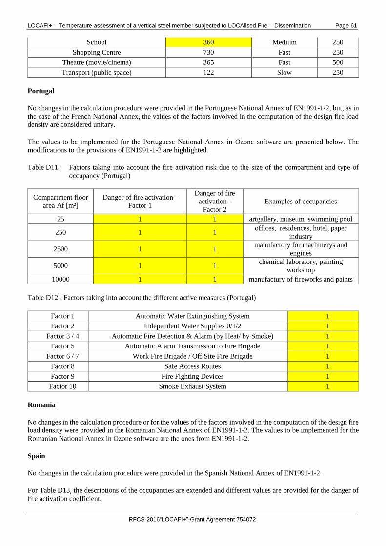
LOCAFI+ – Temperature assessment of a vertical steel member subjected to LOCAlised Fire – Dissemination Page 61
RFCS-2016“LOCAFI+”-Grant Agreement 754072
School 360 Medium 250
Shopping Centre 730 Fast 250
Theatre (movie/cinema) 365 Fast 500
Transport (public space) 122 Slow 250
Portugal
No changes in the calculation procedure were provided in the Portuguese National Annex of EN1991-1-2, but, as in
the case of the French National Annex, the values of the factors involved in the computation of the design fire load
density are considered unitary.
The values to be implemented for the Portuguese National Annex in Ozone software are presented below. The
modifications to the provisions of EN1991-1-2 are highlighted.
Table D11 : Factors taking into account the fire activation risk due to the size of the compartment and type of
occupancy (Portugal)
Compartment floor
area Af [m²]
Danger of fire activation -
Factor 1
Danger of fire
activation -
Factor 2
Examples of occupancies
25 1 1 artgallery, museum, swimming pool
250 1 1 offices, residences, hotel, paper
industry
2500 1 1 manufactory for machinerys and
engines
5000 1 1 chemical laboratory, painting
workshop
10000 1 1 manufactury of fireworks and paints
Table D12 : Factors taking into account the different active measures (Portugal)
Factor 1 Automatic Water Extinguishing System 1
Factor 2 Independent Water Supplies 0/1/2 1
Factor 3 / 4 Automatic Fire Detection & Alarm (by Heat/ by Smoke) 1
Factor 5 Automatic Alarm Transmission to Fire Brigade 1
Factor 6 / 7 Work Fire Brigade / Off Site Fire Brigade 1
Factor 8 Safe Access Routes 1
Factor 9 Fire Fighting Devices 1
Factor 10 Smoke Exhaust System 1
Romania
No changes in the calculation procedure or for the values of the factors involved in the computation of the design fire
load density were provided in the Romanian National Annex of EN1991-1-2. The values to be implemented for the
Romanian National Annex in Ozone software are the ones from EN1991-1-2.
Spain
No changes in the calculation procedure were provided in the Spanish National Annex of EN1991-1-2.
For Table D13, the descriptions of the occupancies are extended and different values are provided for the danger of
fire activation coefficient.
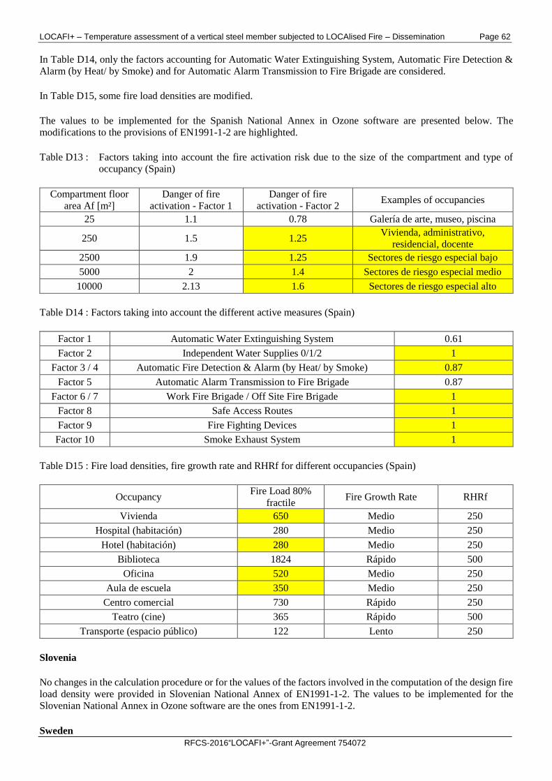
LOCAFI+ – Temperature assessment of a vertical steel member subjected to LOCAlised Fire – Dissemination Page 62
RFCS-2016“LOCAFI+”-Grant Agreement 754072
In Table D14, only the factors accounting for Automatic Water Extinguishing System, Automatic Fire Detection &
Alarm (by Heat/ by Smoke) and for Automatic Alarm Transmission to Fire Brigade are considered.
In Table D15, some fire load densities are modified.
The values to be implemented for the Spanish National Annex in Ozone software are presented below. The
modifications to the provisions of EN1991-1-2 are highlighted.
Table D13 : Factors taking into account the fire activation risk due to the size of the compartment and type of
occupancy (Spain)
Compartment floor
area Af [m²]
Danger of fire
activation - Factor 1
Danger of fire
activation - Factor 2 Examples of occupancies
25 1.1 0.78 Galería de arte, museo, piscina
250 1.5 1.25 Vivienda, administrativo,
residencial, docente
2500 1.9 1.25 Sectores de riesgo especial bajo
5000 2 1.4 Sectores de riesgo especial medio
10000 2.13 1.6 Sectores de riesgo especial alto
Table D14 : Factors taking into account the different active measures (Spain)
Factor 1 Automatic Water Extinguishing System 0.61
Factor 2 Independent Water Supplies 0/1/2 1
Factor 3 / 4 Automatic Fire Detection & Alarm (by Heat/ by Smoke) 0.87
Factor 5 Automatic Alarm Transmission to Fire Brigade 0.87
Factor 6 / 7 Work Fire Brigade / Off Site Fire Brigade 1
Factor 8 Safe Access Routes 1
Factor 9 Fire Fighting Devices 1
Factor 10 Smoke Exhaust System 1
Table D15 : Fire load densities, fire growth rate and RHRf for different occupancies (Spain)
Occupancy Fire Load 80%
fractile Fire Growth Rate RHRf
Vivienda 650 Medio 250
Hospital (habitación) 280 Medio 250
Hotel (habitación) 280 Medio 250
Biblioteca 1824 Rápido 500
Oficina 520 Medio 250
Aula de escuela 350 Medio 250
Centro comercial 730 Rápido 250
Teatro (cine) 365 Rápido 500
Transporte (espacio público) 122 Lento 250
Slovenia
No changes in the calculation procedure or for the values of the factors involved in the computation of the design fire
load density were provided in Slovenian National Annex of EN1991-1-2. The values to be implemented for the
Slovenian National Annex in Ozone software are the ones from EN1991-1-2.
Sweden
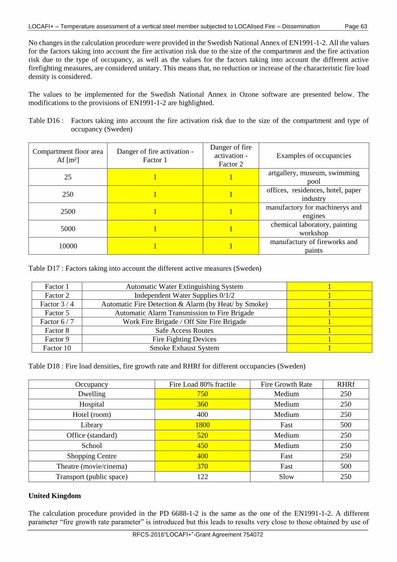
LOCAFI+ – Temperature assessment of a vertical steel member subjected to LOCAlised Fire – Dissemination Page 63
RFCS-2016“LOCAFI+”-Grant Agreement 754072
No changes in the calculation procedure were provided in the Swedish National Annex of EN1991-1-2. All the values
for the factors taking into account the fire activation risk due to the size of the compartment and the fire activation
risk due to the type of occupancy, as well as the values for the factors taking into account the different active
firefighting measures, are considered unitary. This means that, no reduction or increase of the characteristic fire load
density is considered.
The values to be implemented for the Swedish National Annex in Ozone software are presented below. The
modifications to the provisions of EN1991-1-2 are highlighted.
Table D16 : Factors taking into account the fire activation risk due to the size of the compartment and type of
occupancy (Sweden)
Compartment floor area
Af [m²]
Danger of fire activation -
Factor 1
Danger of fire
activation -
Factor 2
Examples of occupancies
25 1 1 artgallery, museum, swimming
pool
250 1 1 offices, residences, hotel, paper
industry
2500 1 1 manufactory for machinerys and
engines
5000 1 1 chemical laboratory, painting
workshop
10000 1 1 manufactury of fireworks and
paints
Table D17 : Factors taking into account the different active measures (Sweden)
Factor 1 Automatic Water Extinguishing System 1
Factor 2 Independent Water Supplies 0/1/2 1
Factor 3 / 4 Automatic Fire Detection & Alarm (by Heat/ by Smoke) 1
Factor 5 Automatic Alarm Transmission to Fire Brigade 1
Factor 6 / 7 Work Fire Brigade / Off Site Fire Brigade 1
Factor 8 Safe Access Routes 1
Factor 9 Fire Fighting Devices 1
Factor 10 Smoke Exhaust System 1
Table D18 : Fire load densities, fire growth rate and RHRf for different occupancies (Sweden)
Occupancy Fire Load 80% fractile Fire Growth Rate RHRf
Dwelling 750 Medium 250
Hospital 360 Medium 250
Hotel (room) 400 Medium 250
Library 1800 Fast 500
Office (standard) 520 Medium 250
School 450 Medium 250
Shopping Centre 400 Fast 250
Theatre (movie/cinema) 370 Fast 500
Transport (public space) 122 Slow 250
United Kingdom
The calculation procedure provided in the PD 6688-1-2 is the same as the one of the EN1991-1-2. A different
parameter “fire growth rate parameter” is introduced but this leads to results very close to those obtained by use of
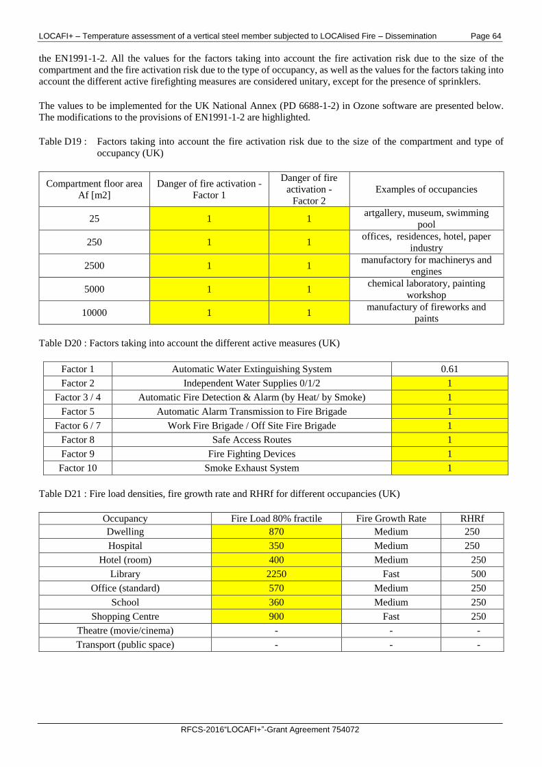
LOCAFI+ – Temperature assessment of a vertical steel member subjected to LOCAlised Fire – Dissemination Page 64
RFCS-2016“LOCAFI+”-Grant Agreement 754072
the EN1991-1-2. All the values for the factors taking into account the fire activation risk due to the size of the
compartment and the fire activation risk due to the type of occupancy, as well as the values for the factors taking into
account the different active firefighting measures are considered unitary, except for the presence of sprinklers.
The values to be implemented for the UK National Annex (PD 6688-1-2) in Ozone software are presented below.
The modifications to the provisions of EN1991-1-2 are highlighted.
Table D19 : Factors taking into account the fire activation risk due to the size of the compartment and type of
occupancy (UK)
Compartment floor area
Af [m2]
Danger of fire activation -
Factor 1
Danger of fire
activation -
Factor 2
Examples of occupancies
25 1 1 artgallery, museum, swimming
pool
250 1 1 offices, residences, hotel, paper
industry
2500 1 1 manufactory for machinerys and
engines
5000 1 1 chemical laboratory, painting
workshop
10000 1 1 manufactury of fireworks and
paints
Table D20 : Factors taking into account the different active measures (UK)
Factor 1 Automatic Water Extinguishing System 0.61
Factor 2 Independent Water Supplies 0/1/2 1
Factor 3 / 4 Automatic Fire Detection & Alarm (by Heat/ by Smoke) 1
Factor 5 Automatic Alarm Transmission to Fire Brigade 1
Factor 6 / 7 Work Fire Brigade / Off Site Fire Brigade 1
Factor 8 Safe Access Routes 1
Factor 9 Fire Fighting Devices 1
Factor 10 Smoke Exhaust System 1
Table D21 : Fire load densities, fire growth rate and RHRf for different occupancies (UK)
Occupancy Fire Load 80% fractile Fire Growth Rate RHRf
Dwelling 870 Medium 250
Hospital 350 Medium 250
Hotel (room) 400 Medium 250
Library 2250 Fast 500
Office (standard) 570 Medium 250
School 360 Medium 250
Shopping Centre 900 Fast 250
Theatre (movie/cinema) - - -
Transport (public space) - - -
LOCAFI+ – Temperature assessment of a vertical steel member subjected to LOCAlised Fire – Dissemination Page 65
RFCS-2016“LOCAFI+”-Grant Agreement 754072
ANNEX E - LOCALISED FIRE PROCEDURE
The localised fire procedure implemented in OZone is based on the work made in the research project RFSR-CT-
2012-00023 LOCAFI - Temperature assessment of a vertical steel member subjected to LOCAlised Fire. The
analytical model for localised fires has been developed within the project with two levels of refinement:
- A model based on numerical integration for implementation into advanced models like SAFIR and Ansys -
“geometric model”;
- A model based on analytical formulae for handmade use or implementation into basic engineering tools like
Excel spreadsheets - “simplified model”.
In both geometric and simplified models, the configurations where the thermal exchanges are drawn by convective
fluxes (member engulfed into the fire or situated inside the smoke layer) are treated by application of the existing
equations available in the EN 1991-1-2. The major heat exchanges, by radiation, are calculated by representing the
fire as a virtual solid flame that radiates in all the directions. The first step of this calculation is again common to the
geometric and simplified models and consists in defining the geometry of the virtual solid flame representing the
localised fire and the distribution of temperature as a function of time.
The shape of the virtual solid flame representing the thermal action of the localised fire may be cylindrical or conical.
The cylindrical shape flame is simpler to deal with but usually represents less accurately the thermal attack induced
by the fire and leads to overestimated radiative heat fluxes. In case the flame length is higher than the ceiling level,
the cylinder or the cone must be truncated and a radiant ring, representing the spreading of the flame under the ceiling,
should be considered outside the truncated cylinder or cone.
The difference between the geometric and simplified models is the calculation method used for the assessment of the
radiative heat fluxes exchanged between the virtual solid flame and the elements.
In order to propose a calculation method without surface integral (that generally requires the implementation into a
solver), the simplified model implemented in OZone was defined on the basis of configuration factors. For simple
shapes like cylinder or ring, direct formulae are available under several conditions. By means of slight adaptations
of the virtual solid flame, these conditions are satisfied and the calculation of radiative heat fluxes can be calculated
using the concept of configuration factor.
The implementation of the simplified model in OZone software considers a conical shape for the virtual solid flame
as it has been demonstrated that this shape is leading to the best flux predictions. The flux is calculated separately for
the 4 faces of the box perimeter of the profile and an average value of this flux is applied to the whole perimeter of
the steel section. This means that the shadow effect is not taken into account. The coupling between localised fire
and compartment fire allows combining the influences of the radiative heat fluxes through the cold zone and of the
convective fluxes in the hot zone. The input data of the “Localised fire” part requires defining the position, diameter
and evolution of HRR with time for a maximum number of 5 fires. The calculation of steel temperatures under the
calculated heat fluxes was already available previously and assumes that the temperature is uniform through the
cross-section.
More detailed information about the simplified model for localised fire implemented in OZone is given in the Final
Report of the research project RFSR-CT-2012-00023 LOCAFI - Temperature assessment of a vertical steel member
subjected to LOCAlised Fire.
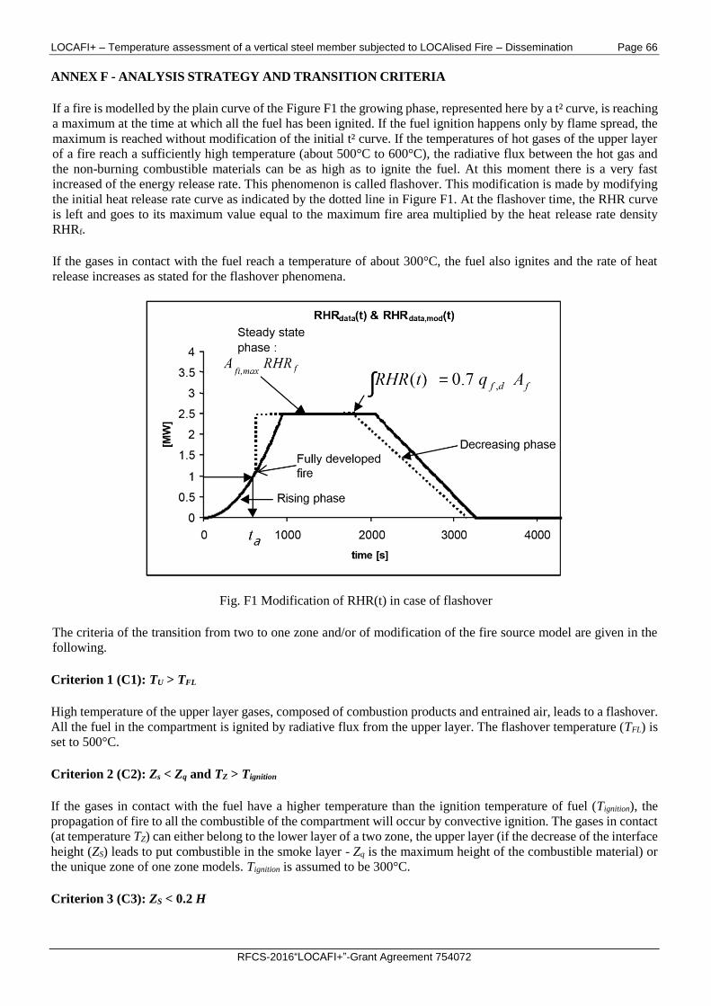
LOCAFI+ – Temperature assessment of a vertical steel member subjected to LOCAlised Fire – Dissemination Page 66
RFCS-2016“LOCAFI+”-Grant Agreement 754072
ANNEX F - ANALYSIS STRATEGY AND TRANSITION CRITERIA
If a fire is modelled by the plain curve of the Figure F1 the growing phase, represented here by a t² curve, is reaching
a maximum at the time at which all the fuel has been ignited. If the fuel ignition happens only by flame spread, the
maximum is reached without modification of the initial t² curve. If the temperatures of hot gases of the upper layer
of a fire reach a sufficiently high temperature (about 500°C to 600°C), the radiative flux between the hot gas and
the non-burning combustible materials can be as high as to ignite the fuel. At this moment there is a very fast
increased of the energy release rate. This phenomenon is called flashover. This modification is made by modifying
the initial heat release rate curve as indicated by the dotted line in Figure F1. At the flashover time, the RHR curve
is left and goes to its maximum value equal to the maximum fire area multiplied by the heat release rate density
RHRf.
If the gases in contact with the fuel reach a temperature of about 300°C, the fuel also ignites and the rate of heat
release increases as stated for the flashover phenomena.
Fig. F1 Modification of RHR(t) in case of flashover
The criteria of the transition from two to one zone and/or of modification of the fire source model are given in the
following.
Criterion 1 (C1): TU > TFL
High temperature of the upper layer gases, composed of combustion products and entrained air, leads to a flashover.
All the fuel in the compartment is ignited by radiative flux from the upper layer. The flashover temperature (TFL) is
set to 500°C.
Criterion 2 (C2): Zs < Zq and TZ > Tignition
If the gases in contact with the fuel have a higher temperature than the ignition temperature of fuel (Tignition), the
propagation of fire to all the combustible of the compartment will occur by convective ignition. The gases in contact
(at temperature TZ) can either belong to the lower layer of a two zone, the upper layer (if the decrease of the interface
height (ZS) leads to put combustible in the smoke layer - Zq is the maximum height of the combustible material) or
the unique zone of one zone models. Tignition is assumed to be 300°C.
Criterion 3 (C3): ZS < 0.2 H
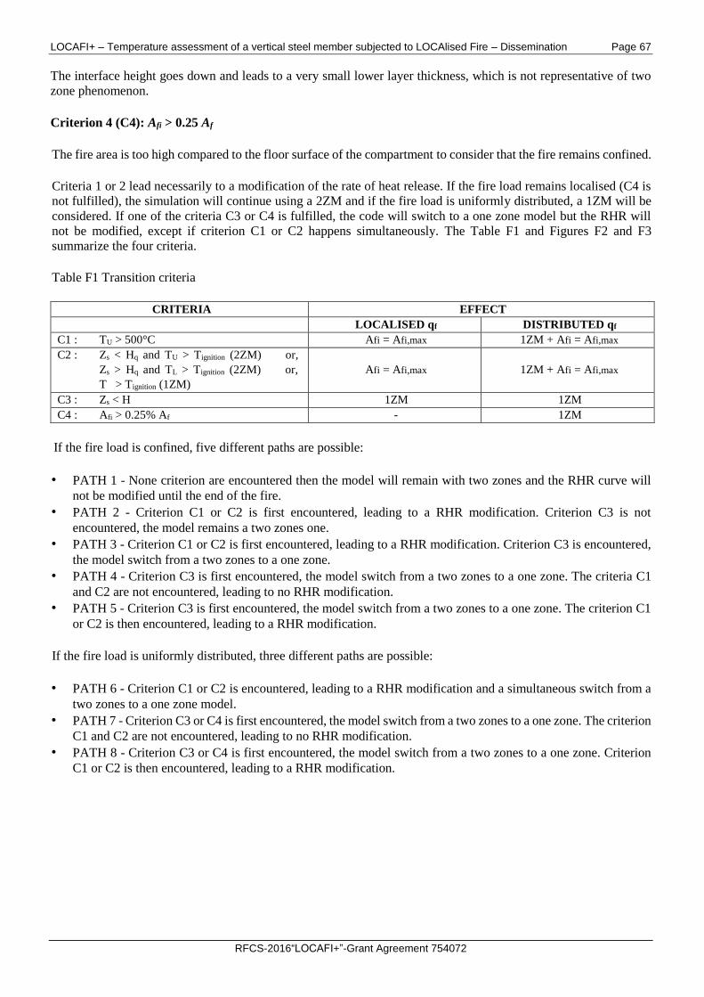
LOCAFI+ – Temperature assessment of a vertical steel member subjected to LOCAlised Fire – Dissemination Page 67
RFCS-2016“LOCAFI+”-Grant Agreement 754072
The interface height goes down and leads to a very small lower layer thickness, which is not representative of two
zone phenomenon.
Criterion 4 (C4): Afi > 0.25 Af
The fire area is too high compared to the floor surface of the compartment to consider that the fire remains confined.
Criteria 1 or 2 lead necessarily to a modification of the rate of heat release. If the fire load remains localised (C4 is
not fulfilled), the simulation will continue using a 2ZM and if the fire load is uniformly distributed, a 1ZM will be
considered. If one of the criteria C3 or C4 is fulfilled, the code will switch to a one zone model but the RHR will
not be modified, except if criterion C1 or C2 happens simultaneously. The Table F1 and Figures F2 and F3
summarize the four criteria.
Table F1 Transition criteria
CRITERIA EFFECT
LOCALISED qf DISTRIBUTED qf
C1 : TU > 500°C Afi = Afi,max 1ZM + Afi = Afi,max
C2 : Zs < Hq and TU > Tignition (2ZM) or,
Zs > Hq and TL > Tignition (2ZM) or,
T > Tignition (1ZM)
Afi = Afi,max 1ZM + Afi = Afi,max
C3 : Zs < H 1ZM 1ZM
C4 : Afi > 0.25% Af - 1ZM
If the fire load is confined, five different paths are possible:
• PATH 1 - None criterion are encountered then the model will remain with two zones and the RHR curve will
not be modified until the end of the fire.
• PATH 2 - Criterion C1 or C2 is first encountered, leading to a RHR modification. Criterion C3 is not
encountered, the model remains a two zones one.
• PATH 3 - Criterion C1 or C2 is first encountered, leading to a RHR modification. Criterion C3 is encountered,
the model switch from a two zones to a one zone.
• PATH 4 - Criterion C3 is first encountered, the model switch from a two zones to a one zone. The criteria C1
and C2 are not encountered, leading to no RHR modification.
• PATH 5 - Criterion C3 is first encountered, the model switch from a two zones to a one zone. The criterion C1
or C2 is then encountered, leading to a RHR modification.
If the fire load is uniformly distributed, three different paths are possible:
• PATH 6 - Criterion C1 or C2 is encountered, leading to a RHR modification and a simultaneous switch from a
two zones to a one zone model.
• PATH 7 - Criterion C3 or C4 is first encountered, the model switch from a two zones to a one zone. The criterion
C1 and C2 are not encountered, leading to no RHR modification.
• PATH 8 - Criterion C3 or C4 is first encountered, the model switch from a two zones to a one zone. Criterion
C1 or C2 is then encountered, leading to a RHR modification.
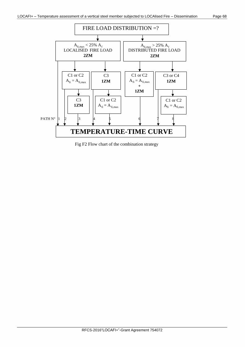
LOCAFI+ – Temperature assessment of a vertical steel member subjected to LOCAlised Fire – Dissemination Page 68
RFCS-2016“LOCAFI+”-Grant Agreement 754072
Fig F2 Flow chart of the combination strategy
FIRE LOAD DISTRIBUTION =?
A fi,max < 25% A f LOCALISED FIRE LOAD
ZM 2
A fi,max > 25% A f DISTRIBUTED FIRE LOAD
2 ZM
TEMPERATURE-TIME CURVE
C1 or C2
A fi = A fi,max
C3
ZM 1
C3
1 ZM
C1 or C2
A fi = A fi,max +
1 ZM
C3 or C4
1 ZM
C1 or C2
A fi = A fi,max
C1 or C2
A fi = A fi,max
PATH N° 1 2 3 4 5 6 7 8
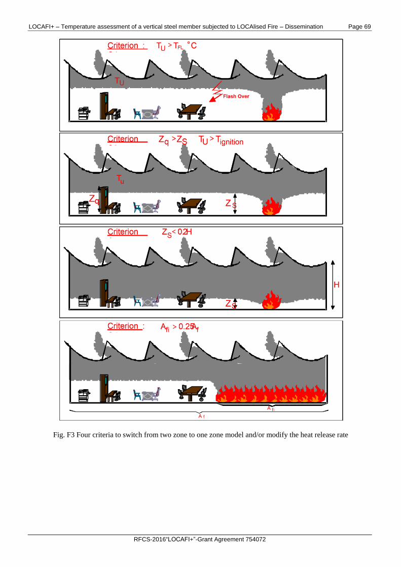
LOCAFI+ – Temperature assessment of a vertical steel member subjected to LOCAlised Fire – Dissemination Page 69
RFCS-2016“LOCAFI+”-Grant Agreement 754072
Fig. F3 Four criteria to switch from two zone to one zone model and/or modify the heat release rate
LOCAFI+ – Temperature assessment of a vertical steel member subjected to LOCAlised Fire – Dissemination Page 70
RFCS-2016“LOCAFI+”-Grant Agreement 754072
BIBLIOGRAPHY
J-F. Cadorin, J-M. Franssen, A tool to design steel elements submitted to compartment fires - OZone V2 - Part 1 :
Pre and post flashover compartment fire model, Fire Safety Journal, accepted for publication in May 2002.
J-F. Cadorin, D. Pintea, J-C Dotreppe, J-M. Franssen, A tool to design steel elements submitted to compartment fires
- OZone V2 Part 2: Methodology and application, Fire Safety Journal, accepted for publication in May 2002.
RFSR-CT-2012-00023 LOCAFI - Temperature assessment of a vertical steel member subjected to LOCAlised Fire,
European Commission, Research Programme of the Research Fund for Coal and Steel, 2015
SFPE Handbook of Fire Protection Engineering, Society of Fire Protection Engineers and National Fire Protection
Association, 2nd Edition, 1995.
G. P. Forney and L. Y. Cooper, The Consolidated Compartment Fire Model (CCFM) Computer Application. VENTS,
Parts I, II, III, IV. NISTIR, National Institute of Standards and Technology, 1990.
G. P. Forney and W. F. Moss, Analysing and exploiting numerical characteristics of zone fire models, Fire Science
& Technology, Vol. 14, No.1 & 2, 49-60, 1994.
M. Curtat, P. Fromy; Prévison par le calcul des solicitations thermiques dans un local en feu, Première partie: le
modèle et le logiciel NAT, Cahiers du CSTC, livraison 327, cahier 2565, mars 1992
J. M. Franssen, Contributions à la modélisation des incendies dans les bâtiments et de leurs effets sur les structures,
Thèse d'agr. de l'ens. sup., F.S.A., Univ. of Liege, 1997.
Eurocode 3: Design of steel structures. Part 1.2 : General rules. Structural fire design. ENV 1993-1-2, CEN,
Bruxelles, may 1995.
Y. Hasemi et T. Tokunaga, Flame Geometry Effects on the Buoyant Plumes from Turbulent Diffusion Flames, Fire
Science and Technology, 4, 15-26, 1984.
Y. Hasemi, S. Yokobayashi, T. Wakamatsu et A. Ptchelintsev, Fire Safety of Building Components Exposed to a
Localised Fire - Scope and Experiments on Ceiling/Beam System Exposed to a Localised Fire, First Int. ASIAFLAM
Conf. at Kowloon, Interscience Communications Ltd, London, 351-360, 1995.
A. Ptchelintsev, Y. Hasemi et M. Nikolaenko, Numerical Analysis of Structures Exposed to Localised Fire, First Int.
ASIAFLAM Conf. at Kowloon, Interscience Communications Ltd, London, 539-544, 1995.
T. Wakamatsu, Y. Hasemi, Y. Yokobayashi and A. Ptchelintsev, Experimental Study on the Heating Mechanism of
a Steel Beam under Ceiling Exposed to a Localised Fire, second INTERFLAM 96 conference, Cambridge, 509-518,
1996.
Franssen, Jean-Marc (ed.). Structures in fire : proceedings of the first international workshop. Copenhagen, Denmark,
19th and 20th of June, 2000. University of Liege (2000), s.211 - 224.
CEC Agreements 7210-SA/211/318/518/620/933. Development of design rules for steel structures subjected to
natural fires in Closed Car Parks. Final Report, February 97.
CEC Agreements 7210-SA/125/126/213/214/323/423/522/623/839/937. “Competitive Steel Buildings through
Natural Fire Safety Concept”, Technical report n°6; July 97.
L. Y. Cooper, VENTCF2: an Algorithm and Associated FORTRAN 77 Subroutine for Calculating Flow through a
Horizontal Ceiling/Floor Vent in a Zone-type Compartment Fire Model, Fire Safety Journal, Volume 28, Issue 3,
April 1997, Pages 253-287.
LOCAFI+ – Temperature assessment of a vertical steel member subjected to LOCAlised Fire – Dissemination Page 71
RFCS-2016“LOCAFI+”-Grant Agreement 754072
L. Y. Cooper, Calculating Combined Buoyancy- and Pressure-driven Flow through a Shallow, Horizontal, Circular
Vent: Application to a Problem of Steady Burning in a Ceiling- vented Enclosure, Fire Safety Journal, Volume 27,
Issue 1, July 1996, Pages 23-35.
X. C. Zhou and J. P. Gore, Air Entrainment Flow Field Induced by a Pool Fire, Combustion and Flame, Volume 100,
Issues 1-2, January 1995, Pages 52-60.
Marc L. Janssens, An Introduction to Mathematical Fire Modeling, 2nd edn.; Technomic Publishing Co., Lancaster,
PA, USA, 2000, xi, 259 pages, paperback, ISBN 1-56676-920-5
B. Karlsson, J. G. Quintiere, Enclosure Fire Dynamics, CRC Press 2000.