Embed Size (px)
Citation preview

Project Choices – MECH4240 Fall 2017 The rules:
• Rank your top 4 choices, in order, giving a list with project number and project name, and email those by Wednesday, 6 pm to Amanda Skalitzky ([email protected]). Add any other information you want to provide as to capabilities. In most cases students are most likely to get their first or second choice. Be aware that some projects, although listed below, may be dropped. And some projects must be performed because of existing contracts. For that reason, students must include in their list of 4 projects one of Human Exploration Rover, AFRL and CanSat.
• If we don’t hear from you, you will be assigned to a team that needs people. • Some projects require American citizenship (11,12,17,18). • Don’t worry about the project cost, that is not your responsibility • This file is on the course website at http://www.eng.auburn.edu/~dbeale/MECH4240-50/
There are 3 people of interest: 1. (Industrial) Sponsor – the primary stakeholder and project review (midterm and final review) evaluator. You can contact them between now and Sunday at 6 pm if contact information is given below. 2. Technical Advisor – the technical person with whom you meet periodically to monitor and offer technical advice (but not lead or manage!) as you proceed, and 3. Overlord – usually Dr. Beale unless otherwise stated, making sure that the whole process runs smoothly and course requirements are met by all student teams.

11. AFRL University Design Challenge, Space Debris Mitigation (7-10 students) http://www.afrlchallenge.com/
Sponsor: Air Force Research Laboratory (AFRL) – should not be contacted as this time. Technical Advisors: Halverson/Skalitsky/Beale This is the 6th year of the competition, with 17 and 9 universities and 3 service academies competing in mid-April. AU has been the best performing team! Features: Highly creative solutions sought, job opportunities, creative and functional design wins, competition in early April, all-expense paid trip to location TBD. Will need some students to be taking the embedded systems course. Background: Rocket bodies from decades of launch of satellites into Earth orbit are the largest component of space debris by mass, and they may pose a significant present and future threat to operation of space systems in certain orbits. Most of these objects will remain in place for several more decades before they re-enter the Earth’s atmosphere and eventually burn up. The Air Force and others are interested in long term reduction in the number of large rocket bodies in low earth orbits, especially near-polar and sun synchronous orbits, to help preserve and extend the effective use of space. It may be feasible to attach propulsion systems to these bodies, but another, possibly less difficult alternative, is to clear critical orbits and accelerate de-orbiting through drag augmentation of the large debris objects. A specific technical challenge is the final engagement with rocket bodies, and the attachment and deployment of drag-enhancing devices to increase drag by an order of magnitude. A New Design Concept: This Senior Capstone Design project is to develop a satellite payload that can be deployed from the satellite, positively engage with a representative rocket body and deploy a drag enhancing device while staying attached to the rocket body. It is assumed that the satellite hosting the payload will maneuver near and maintain proximity with the rocket body at an initial distance of 5 meters. For a demonstration, the relative motion between the satellite and the rocket body will be up to 10 cm/s magnitude in translation– in any combination of three axes – and that the body may be tumbling in one axis with a period of between 5 seconds and one minute (60 seconds), implying body rotation rates up to 60 degrees/s. The cylindrical rocket body will be 2 meters long, with a diameter of 0.75 m and is closed off at each end. The body test article has a mass of between 50 and 100 kg. A final demonstration will include two major phases, to be conducted in sequence. First, the payload, installed in a simulated satellite, will deploy and separate from the satellite and grapple, capture or otherwise positively engage the tumbling rocket body. Second, while attached to the rocket body, and without having been compromised by the initial engagement, the payload will deploy a drag enhancement device or system. The drag enhancement will be designed to increase the ratio of the area to mass of the assembly (the rocket body combined with the drag enhancer) by 10 times compared to the area/mass of the rocket body alone. The size and mass of the payload packaged in the satellite should be minimized and the area it consumes on the face of the satellite in the direction of deployment should also be minimized. The satellite will include a video camera that may be used to locate and quantify motions of the rocket body. The overall system design should be for operation in space, and should accommodate, but not rely on gravity and atmospheric effects present in the ground demonstration.

The University Design Challenge will culminate in a ground demonstration of the student designs. Skills Needed for This Work: (1) Basic understanding of dynamics. (2) Simulation skills to account for gravity and atmospheric effects. (3) Mechanical and Electrical design skills for including evaluation of mechanisms for deployment. (4) Test planning and testing skills to ensure capability of a finished design.

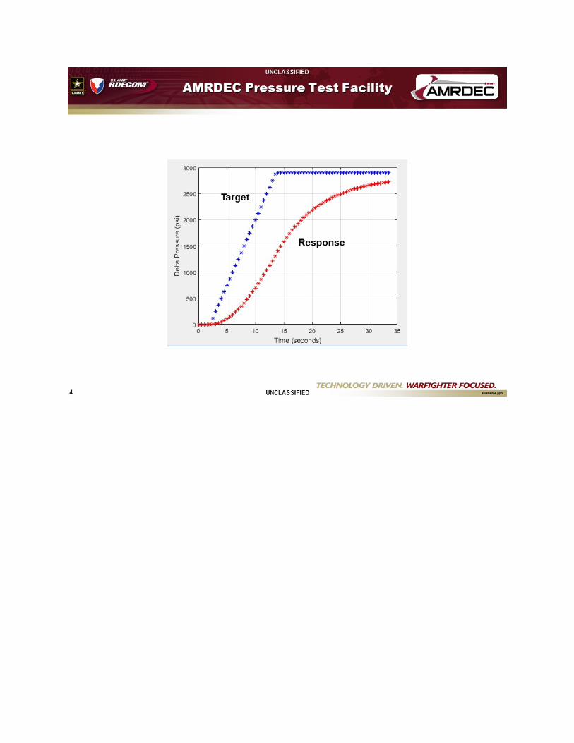
12. AMRDEC Pressure Test Facility (3-4 students) Sponsor: Taylor Owens, (256) 842-0813, [email protected] Technical Advisor: Beale


13. CanSat http://www.cansatcompetition.com/ 4 students Sponsor: Alabama Space Grant, competition rules Technical Advisor: Halverson/Beale Description: A team of students built a prototype and did some testing. Your objective is a competition ready prototype and attend at compete at the competition event. This a small satellite http://www.cansatcompetition.com/ that fits within a soft drink can or similar structure, and is launched by a rocket (rocket supplied, not to be designed). The 2017 mission simulates a solar powered sensor payload traveling through a planetary atmosphere sampling the atmospheric composition during flight. The overall CanSat system is composed of two primary components, a science vehicle and a re-entry container that protects the vehicle during ascent, "near-apogee" deployment and initial re-entry/descent. When deployed from the rocket the re-entry container shall descend with the vehicle secured in the container. Either the container shall release the vehicle or the science vehicle shall release itself from the container any time after deployment from the rocket. The intention of the container is to protect the science vehicle from the violent deployment and provide a more stable and less forceful release environment. When the science vehicle is released from the container, it shall glide in a circular pattern with a diameter of no more than 1000 meters. During flight, the glider science vehicle shall sample the air pressure and temperature at a rate of 1 sample per second and transmit the data to a ground station. The glider shall contain a magnetometer and a pitot tube to measure heading and speed. When the science vehicle lands, transmission shall automatically stop and an audio beacon shall be activated automatically for recovery if the solar cells can support the beacon power requirements.

14. Baja SAE, 5 students Technical Advisor/Sponsor: Dr. Jordan Roberts [email protected] Students will gather domain knowledge, document, design, test, and build a working off-road vehicle for competition meeting the requirements of rules provided by the Society of Automotive Engineers (SAE). Functions and subsystems within the team include, but are not limited to, marketing and recruiting, frame, suspension, steering, brakes, ergonomics, electrical and data, and drivetrain. Senior design students will be integrated into an existing working team and must produce documented work at regular intervals and meetings. A working car must be demonstrated prior to the conclusion of the second semester, at a minimum.
Baja SAE® students are tasked to design and build an off-road vehicle that will survive the severe punishment of rough terrain. Each team's goal is to design and build a single-seat, all-terrain, sporting vehicle whose structure contains a single driver. The vehicle is to be a prototype for a reliable, maintainable, ergonomic, and economic production vehicle, which serves a recreational user market.
The object of the competition is to provide SAE student members with a challenging project that involves the design, planning and manufacturing tasks found when introducing a new product to the consumer industrial market. Students must function as a team to not only design, build, test, promote, and race a vehicle within the limits of the rules, but also to generate financial support for their project and manage their educational priorities. All vehicles are powered by a ten-horsepower Intek Model 19 engine donated by Briggs & Stratton Corporation.

15. Biohorizons - BioHorizons MTS Specimen Clamp (3 students) Sponsor: Thomas P. Lewis, Manager, Product Engineering, [email protected] (205) 986-7933, www.biohorizons.com Technical Advisor: Beale BioHorizons, Inc. is a Birmingham, AL based company that designs, manufactures and markets dental implants and associated restorative products in the United States and around the world. The company began in 1994 and launched its initial Implant product line (Maestro) in 1997. Since that time it has grown to nearly 400 employees around the world and increased its product offerings to multiple parallel wall and tapered implant designs and associated prosthetics. FDA and international regulatory bodies require testing to demonstrate implant and transmucosal abutment assembly fatigue strength. The governing international standard for this testing is ISO 14801:2016. The purpose of this project is design a specimen clamp that will hold a dental implant and abutment assembly for static and fatigue testing on the 858 mini-Bionix II Test Systems located at BioHorizons, Inc. in Birmingham, AL. In addition to the clamp, the design will include other parts that attach the clamp to the test equipment and a 37°C saline solution chamber to accommodate testing when implants are attached to ceramic bonded abutments. After completion of the design, three identical sets of hardware will be manufactured and retained at BioHorizons for use in testing. 858 Mini Bionix II System 500 lbs Load Cell Typical Implant Abutment Assembly Typical Implant with Ceramic Abutment Assembly Typical Endcap to Ensure Applied Load at 13mm From Clamping Plane Requirements for the design: 1. Compliant with international standard ISO 14801:2016 (Dynamic loading test for endosseous dental implants). 2. Designed to fit MTS 858 Mini Bionix II test system. 3. Adjustable to accommodate variable implant lengths and diameters. 4. Accommodate testing in both air and temperature controlled 37°C saline solution. 5. Drawings and specifications to allow for future manufacturing of additional fixtures.

16. Freedman Seating, Lightweight Foldaway Seat (2 teams of 4 students each)
Sponsor and Technical Advisor: Freedman Seating Company, Chicago Illinois, Michael Moffa, [email protected] Scope Document: Lightweight Foldaway Seat, rev 1 Fall/Spring 2017/2018 Academic year Department of Mechanical Engineering, Auburn University Dr. David Beale, Professor Mechanical Engineering, Faculty Advisor Mr. Michael Moffa, Technical Director, Freedman Seating Company, Company Advisor/Sponsor Scope: The project is to develop a seat to replace Freedman Seating Company’s (FSC) current 3pt Foldaway family of forward facing seat platforms. The design must encompass all the current configurable options available on 3pt Foldaway seats. A minimum target mass decrease of 30% in the seat and mounting structure platform is expected. The use of lightweight materials, both ferrous and nonferrous, advanced composites and non-typical polymers or other applicable materials is expected. The proposed designs will need to be competitive on a cost comparable basis and be manufactural in the same quantities as the current platform. The production rate is up to 150 seats a day. The seat will need to be compliant to all Federal motor vehicular standards, including CFR 49 571.207, 210, 225 and 302. A minimum requirement for Type 2 (3 point belts) is required. Grab handles must meet APTA Whitebook requirements. Vehicle mounting points will be required in the same 3d space locations as current Foldaway platforms. Seat and structural design elements, locations and means are open to support design goals. Seat fatigue life will be same or greater than current Foldaway platform. End of manufacturing process configuration management is required. Typical configured options include: headrest, armrest, grab handle. Options will also be designed to be lightweight. Consideration will be given to packaging for shipment to maximize container load density and minimize shipping costs. Freedman Seating Company will supply: Prior to project initiation, technical support and guidance on seating system requirements for passenger vehicles will be provided. Technical Advisor will be available for project progress reviews at weekly intervals. Funding for sample and prototypes materials for molds, tools and finished samples will be supplied as an initial sponsor gift at the beginning of spring semester and refunded as needed. Comment from Mike Moffa: I think it is going to need two teams. The reason for this is that they have to meet the same Federal standards but are two vastly different seats. The Featherweight is our volume seat and we make about 1000 a day, the Foldaway is a double seat and folds up against the wall. We only make 150 Foldaways a day so it is a lower volume seat. The students assigned to the project should take a ride in the Tiger Transit busses. They have both seats installed in the vehicles.
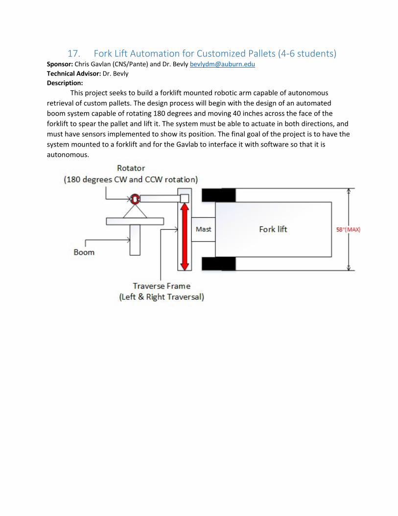
17. Fork Lift Automation for Customized Pallets (4-6 students) Sponsor: Chris Gavlan (CNS/Pante) and Dr. Bevly [email protected] Technical Advisor: Dr. Bevly Description:
This project seeks to build a forklift mounted robotic arm capable of autonomous retrieval of custom pallets. The design process will begin with the design of an automated boom system capable of rotating 180 degrees and moving 40 inches across the face of the forklift to spear the pallet and lift it. The system must be able to actuate in both directions, and must have sensors implemented to show its position. The final goal of the project is to have the system mounted to a forklift and for the Gavlab to interface it with software so that it is autonomous.

18. Harvesting Water from AWGs (Atmospheric Water Generators) (5 or 6 students)
Sponsor: HDIAC, Technical Advisor: Beale Limited access to potable water is a significant challenge for the Warfighter deployed in a harsh, remote, or resource-poor environment. HDIAC is seeking to promote R&D efforts that advance the capabilities of a class of technologies known as atmospheric water generators (AWGs). These devices extract water vapor from the air and collect it for easy use. Methods for collection include, but are not limited to: passive capture; electrically-powered condensation; exploiting temperature gradients; and the use of desiccant salts. Recent advances in this space have applied novel synthetic porous metal-organic micro-materials to extract substantial volumes of water from low-moisture environments, powered only by solar energy. Successful projects may pertain to lowering or eliminating electricity consumption by an AWG; boosting the collection yield in dry or arid conditions; miniaturizing or re-designing a device for better portability; or a novel approach not listed here. HDIAC anticipates that the project will generate original data, a final technical report/presentation, and potentially produce a working prototype.

19. Helicopter Ground Resonance (5 students) Sponsor: Professor Bielawa, Technical Advisor: Dr. Flowers ([email protected])


20. Hospital Bed Compatible IV Pole (3 students) Sponsor: xxxx Technical Advisor: Dr. Zabala [email protected] The purpose of this project is to design and build an IV pole that has the capability to quickly and easily clamp to a mobile hospital bed, have the base retracted upward as to not impede movement of the hospital bed once the pole is attached, and allow for the base to be extended for detachment and relocation of the pole. The design needs to be easy to use, ergonomic, and provide minimal exposure of the base for ease of transportability and storage.

21. Human Exploration Rover, April 2018 Competition, 8-10 students
Description: To find site, search “NASA Human Exploration Rover Challenge”. https://www.nasa.gov/roverchallenge/home/index.html Sponsor: As defined by competition rules. Technical Advisor: Kyle Kubik, [email protected] This is like a hybrid bicycle with 2 peddlers, and 4-wheel vehicle drive train, chassis and suspension. This will be our 6th year entering the competition. Rovers will be human-powered and carry two students, one female and one male, over a half-mile obstacle course of simulated extraterrestrial terrain of craters, boulders, ridges, inclines, crevasses and depressions. As a part of the challenge, and before traversing the course, unassembled rover entries must be carried by the drivers to the course starting line with the unassembled components contained in a volume of 5 feet by 5 feet by 5 feet (dimension requirements). At the starting line, the entries will be assembled, readied for racing, and evaluated for safety. Assembly occurs one time prior to the first course run. Features: Vehicle dynamics training, machining, composites. Learn from and use “legacy”, consider athletic riders. Job opportunities. All-expense paid trip to competition in Huntsville, April 2018
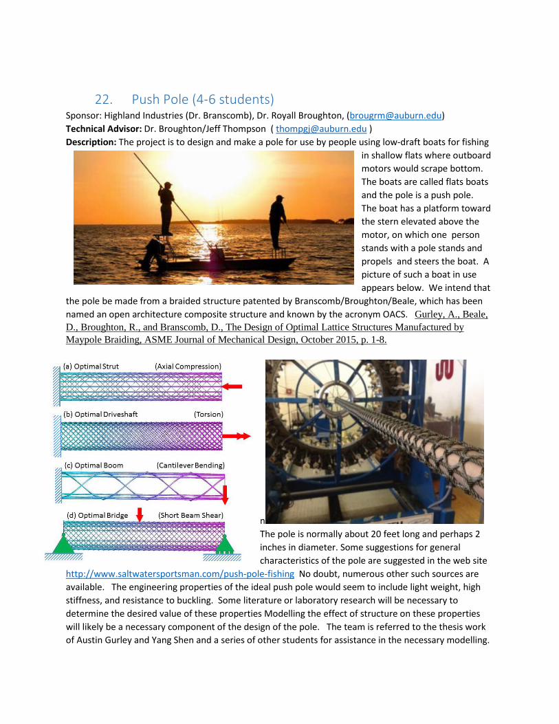
22. Push Pole (4-6 students) Sponsor: Highland Industries (Dr. Branscomb), Dr. Royall Broughton, ([email protected]) Technical Advisor: Dr. Broughton/Jeff Thompson ( [email protected] ) Description: The project is to design and make a pole for use by people using low-draft boats for fishing
in shallow flats where outboard motors would scrape bottom. The boats are called flats boats and the pole is a push pole. The boat has a platform toward the stern elevated above the motor, on which one person stands with a pole stands and propels and steers the boat. A picture of such a boat in use appears below. We intend that
the pole be made from a braided structure patented by Branscomb/Broughton/Beale, which has been named an open architecture composite structure and known by the acronym OACS. Gurley, A., Beale, D., Broughton, R., and Branscomb, D., The Design of Optimal Lattice Structures Manufactured by Maypole Braiding, ASME Journal of Mechanical Design, October 2015, p. 1-8.
nThe pole is normally about 20 feet long and perhaps 2 inches in diameter. Some suggestions for general characteristics of the pole are suggested in the web site
http://www.saltwatersportsman.com/push-pole-fishing No doubt, numerous other such sources are available. The engineering properties of the ideal push pole would seem to include light weight, high stiffness, and resistance to buckling. Some literature or laboratory research will be necessary to determine the desired value of these properties Modelling the effect of structure on these properties will likely be a necessary component of the design of the pole. The team is referred to the thesis work of Austin Gurley and Yang Shen and a series of other students for assistance in the necessary modelling.


![Project Sponsor choices - files.meetup.com Sponsor choices.pdf · Microsoft PowerPoint - Project Sponsor choices [Compatibility Mode] Author: CIO Created Date: 12/6/2016 10:43:56](https://img.pdfslide.net/doc/110x75/5f0abc117e708231d42d1500/project-sponsor-choices-files-sponsor-choicespdf-microsoft-powerpoint-project.jpg)