Embed Size (px)
Citation preview

PROJECT DESCRIPTION STATEMENT
To remove garages approved in PA 7952/06, install a stone/marble
cutting machine with overlying roof and gantry and carry out
additions and alterations
Xewkija - Gozo
TN 144863
_________________________________________________________
May 2012
TRK 144863 - Document - (26a) Revised PDS [] - DocumentID - 2037188 - Document Dated - 20/09/2012 11:49:04 - msult - Page 1 of 52 26a

2
Report Reference: This report has been drawn up by Mr. George Said on behalf of AF Ellis Ltd. with respect to the alterations and installation of marble cutting machinery at an existing and operation concrete brick processing plant at the Xewkija industrial estate. This Project Description Statement was prepared in support of tracking application number TN 144863.
George Said BA(Hons) MA Geog
Jasmine Court Apartment No. 4, Triq Guze Ellul. Pieta, PTA 1034
E‐mail: [email protected]; Mob: +356 79562526; Tel: +356 21226041
TRK 144863 - Document - (26a) Revised PDS [] - DocumentID - 2037188 - Document Dated - 20/09/2012 11:49:04 - msult - Page 2 of 52 26a

3
Table of Contents
1 Introduction 5 2 Background 7 3 Details of the Developer 9 Employees 9 4 The selected Site 10 Site Location 10 Access 11 Surrounding Land uses 11 5 Current Operations on Site 13 6 Proposed structural modifications to the existing plant 15 Objectives of the development 15 Components of the proposed development 15 Services to be available on site 17
7 Proposed Operations and Equipment to be installed on site 18
New industrial Operations 18 Marble cutting machines 19 Barasanti Gangsaw 19 Pedrini Bridge Saw 20 Base Jaw Crusher 21
8 Proposed operations of the marble cutting machines 23 Operations 23 By-Products 25 9 Expected Waste streams to be generated by the marble cutting machines 26 Marble cutting operational process 28 Gravels, broken slabs and chips 28 Plastic and Wood 28 Municipal Waste 28 Grey and Sewerage Effluent 29 10 Quantification of Solid Waste flows from the production process 30 Marble Chip Wastes 30 Liquid Wastes 30 Plastic and Wood 31
TRK 144863 - Document - (26a) Revised PDS [] - DocumentID - 2037188 - Document Dated - 20/09/2012 11:49:04 - msult - Page 3 of 52 26a

4
11 Solid Waste Management of the Facility 32 Utilisation of waste in Concrete Bricks 32 Production of Terazzo 33 Quantities 33 12 Liquid waste management of the facility 34 Waste Water 34 Waste Water Collection 35 Treatment and Disposal of Wash Water 35 13 Emissions from the facility 38 14 Water Management 39 15 Potential impacts and Mitigation measures 40 16 Conclusions 41 Annex 1 43 Annex 2 45
TRK 144863 - Document - (26a) Revised PDS [] - DocumentID - 2037188 - Document Dated - 20/09/2012 11:49:04 - msult - Page 4 of 52 26a

5
1.0 INTRODUCTION
1.1 This technical report has been compiled in accordance with the general
guidelines which have been issued by the Environment Protection Directorate
(EPD). The design and supervision of the proposed project are the responsibility
of Perit Salvu Micallef.
1.2 This document presents a Project Description Statement (PDS) for the set up of
marble cutting machinery facility at an existing concrete brick plant which is located
within the industrial zone of Xewkija as identified in the Gozo and Comino Local Plan.
This report gives a brief description of the ongoing process at the concrete brick
processing plant together with the additional processes which shall be introduced
within the site.
1.3 In addition, this technical report also presents a solid and liquid waste management
work plan for the operations of the proposed marble processing application. This
proposed plan will be endorsed by the operator of this concrete brick plant by ensuring
that the solid and liquid wastes which are generated are properly disposed of by
means of an identified flow disposal systems which have been integrated into the
production process and are explained in detail in the respective sections 9 to 12 of the
report. This is of a benefit to the operator and also to the surrounding environment.
1.4 The timing and main reasons behind this planning application are the immediate
installation of these marble cutting machines in order to compliment the existing
concrete brick production. The purchase of this machinery will enable the company to
produce a wide range of high value added products and will place it in a position to
also produce efficiently marble slabs of various thicknesses according to the client
needs. An added value would be derived from the cutting of such slabs into tiles for
commercial and domestic use by meeting the current demand such specific slab sizes.
TRK 144863 - Document - (26a) Revised PDS [] - DocumentID - 2037188 - Document Dated - 20/09/2012 11:49:04 - msult - Page 5 of 52 26a

6
Thus the installation and operation of the proposed machinery will better position the
company to tap both the indigenous market for marble slabs as well as to explore
export possibilities. The details of the machinery which shall to be introduced on site is
presented in the architectural drawings which are included in Annex 2 of this report.
1.5 It is intended that the Project will be designed to high specification including
conformance with European Union (EU) policies on the operation of the marble cutting
machines and also on waste management and good practices. This project seeks to:
• Provide modern and environmentally sound method of treating and
disposing of non-hazardous waste streams;
• Provide the necessary infrastructure for the proper disposal of waste by
the date as stipulated in the Solid Waste Management Strategy;
• Ensures that the marble cutting operations are kept to optimum levels
with the necessary dust mitigating measures.
1.6 According to the Environmental Impact Assessment (EIA) Regulations (LN 114/2007),
this development proposal may fall under schedule 1. Accordingly the Project
Description Statement (PDS) which is being presented it is intended to provide all the
required information which may help MEPA to determine whether an EIA is required or
not.
TRK 144863 - Document - (26a) Revised PDS [] - DocumentID - 2037188 - Document Dated - 20/09/2012 11:49:04 - msult - Page 6 of 52 26a

7
2.0 BACKGROUND
Background
2.1 The applicant, Mr Anthony Ellis, is the Director of AF Ellis Ltd is a long established tile
and manufacturing firm. Its origins date back to 1932 when a young Gozitan
entrepreneur, Anthony Farrugia Ellis started manufacturing hand-made patterned tiles.
Today, it has gained a strong market share and operates from retail outlets located
both in Malta and Gozo run by successive generations of the Ellis family.
2.2 The company is one of the major players in the production and importation, of tiles and
has over seventy five years of experience in the industry.
2.3 Tile-making and subsequently, marble manufacturing were originally carried out in the
company's premises located in the centre of Victoria which were acquired by the
company's founder. The current premises are situated in an area which has become
increasingly built-up, resulting in the need to re-locate to an industrial zone. Such need
arises not only from the constraints of the present location but also form internal
pressure to expand the operations in order to be more competitive and efficient in the
firms operations.
2.4 In 1991, the company had sought to minimise the problems resulting from the
constraints of the existing premises in Victoria by moving the majority of its operations
to a new factory set out on area of 5,000 square metres, located at Xewkija Industrial
Estate. Since 1991, it intended to set up a state-of-the-art manufacturing process with
high levels of technology. The company had in the early 90’s commenced its
installation for the cutting and polishing of marble and granite as well as the cutting
marble blocks. Investment in the plant included a computer-programmed cutter, a 12
head polisher and an edge-milling machine. The company has already invested
TRK 144863 - Document - (26a) Revised PDS [] - DocumentID - 2037188 - Document Dated - 20/09/2012 11:49:04 - msult - Page 7 of 52 26a

8
heavily in technology and has taken great care to choose the best machinery in each
relative sector in which it operates as it firmly believes that investment in technology
leads to higher productivity and better quality products.
2.5 However, after a division of the family firm in 2001, this machinery is now being
managed by different shareholders. Such division also resulted that the site was
segmented into two, where the portion of the undeveloped part was transformed into a
brick plant.
2.6 The company is now intending to expand the current operations at this industrial plant
in Xewkija and a planning application has been submitted to undergo some minor
alterations within the site and also the installation of the marble cutting machines.
TRK 144863 - Document - (26a) Revised PDS [] - DocumentID - 2037188 - Document Dated - 20/09/2012 11:49:04 - msult - Page 8 of 52 26a

9
3.0 DETIALS OF THE DEVELOPER
3.1 The developer of this site is Mr. Tonio Ellis who has been in the business of tile
manufacturing for the past 30 years. The continuous growth and intensification of the
tile manufacturing is creating demand for high end products and thus a more
elaborated set up of cutting machines is required in order to meet the required
demands and also respects the surrounding environment.
3.2 Marble cutting and also tile manufacturing offers a number of challenges, the major
one being the control of dust dispersion from the cutting process and also the
management of the generated marble sludge. Professional industrial operations must
not only focus solely on the output of their products but also must balance the benefits
of this specific industry with environmental sustainability. This is the main objective of
the proposed development in terms of the installation of the marble cutting machines at
the existing brick processing plant and its operations together with the specific site
modifications where such development is being earmarked.
Employees 3.3 In view of the current concrete brick operations unit Mr. Ellis at present is employing 8
full time persons. These are as follows:-
1 Director
1 Technical Manager
1 Foreman
2 Drivers
1 Clerk
2 Skilled labourers
TRK 144863 - Document - (26a) Revised PDS [] - DocumentID - 2037188 - Document Dated - 20/09/2012 11:49:04 - msult - Page 9 of 52 26a

10
3.4 Mr. Ellis is the owner and director of this industrial plant unit. In view of the proposed
development he will be adding another 2 skilled labourers to the existing workforce.
TRK 144863 - Document - (26a) Revised PDS [] - DocumentID - 2037188 - Document Dated - 20/09/2012 11:49:04 - msult - Page 10 of 52 26a

11
4.0 THE SELECTED SITE
Site Location 4. 1 As stated earlier, the site is located within the industrial zone in the locality of Xewkija
as targeted by the local plan. The site is subject to policy GZ-CMRC-6 which outlines
particular conditions for such industrial site. The details of such policy are as follows:-
GZ-CMRC-6: Areas are indicated at Xewkija on MAP 14.13-A to accommodate Use Classes 11 and 12 (Use Classes Order, 1994) micro-enterprises. A Business Incubation Centre on one of the sites would be favourably considered. The design of the sites shall take into consideration the following:
a) the buildings shall have a maximum height of not more than 10 m. above the finished surrounding surfaces; b) at least 30% of the site shall be left as open space to accommodate vehicular circulation and landscaping; c) preferably at least 25% of the built-up area should be allocated for warehousing; d) services should be directed through underground conduits; and e) a perimeter of at least 3 m. shall be left around the site for soft landscaping. Trees employed in this stretch shall have a mature height of 3 m. or more and shall conform to the approved Guidance on Planting. This requirement may be partially waived on sites which are already committed by development.
4. 2 The area is already serviced with the basic service utilities. In fact the site is connected
to the power and water supply as well as sewerage, and telephone networks. The
facility does not house a generator on site since it has a direct three phase supply from
the nearby industrial area.
4. 3 The site covers 5,000 square meters and consists of a new complex of buildings,
which are being utilised for the production of cement tiles and ancillary products. In all,
this complex has three building units plus parking spaces for 14 vehicles. The existing
brick plant facility can be viewed in the aerial photo which has been included below.
TRK 144863 - Document - (26a) Revised PDS [] - DocumentID - 2037188 - Document Dated - 20/09/2012 11:49:04 - msult - Page 11 of 52 26a
12
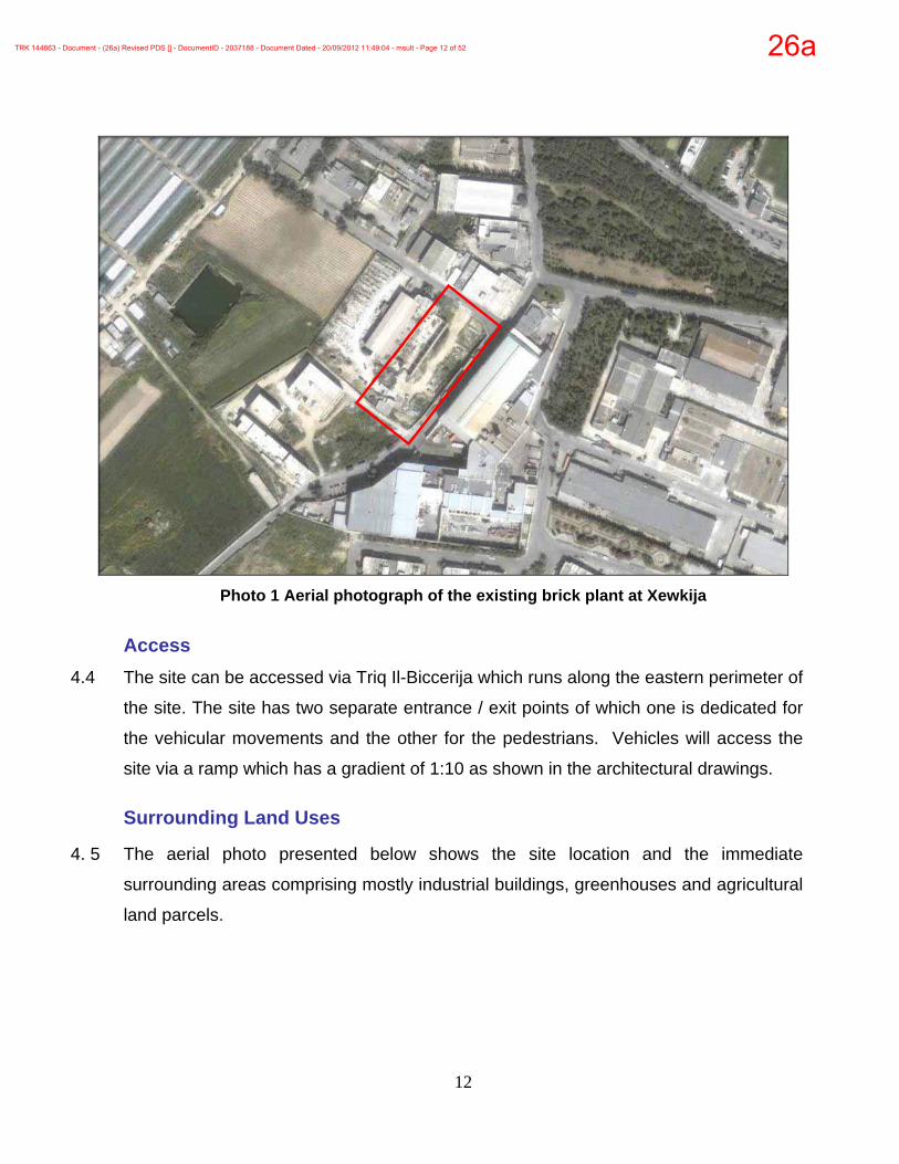
Photo 1 Aerial photograph of the existing brick plant at Xewkija
Access
4.4 The site can be accessed via Triq Il-Biccerija which runs along the eastern perimeter of
the site. The site has two separate entrance / exit points of which one is dedicated for
the vehicular movements and the other for the pedestrians. Vehicles will access the
site via a ramp which has a gradient of 1:10 as shown in the architectural drawings.
Surrounding Land Uses
4. 5 The aerial photo presented below shows the site location and the immediate
surrounding areas comprising mostly industrial buildings, greenhouses and agricultural
land parcels.
TRK 144863 - Document - (26a) Revised PDS [] - DocumentID - 2037188 - Document Dated - 20/09/2012 11:49:04 - msult - Page 12 of 52 26a

13
Photo 2 Aerial photo of the site and surrounding land uses
Legend
Agricultural Industrial Residential Site
The existing Industrial complex forms part of a
complex of industrial developments in the Xewkija
area. These industries were relocated to this area
which is specifically designated for industrial
development since their activities which were
operating with the residential areas were
considered incompatible with the surrounding urban environment.
TRK 144863 - Document - (26a) Revised PDS [] - DocumentID - 2037188 - Document Dated - 20/09/2012 11:49:04 - msult - Page 13 of 52 26a

14
5.0 CURRENT OPERATIONS ON SITE
5.1 At present the site houses a concrete brick manufacturing plant which was approved
as per permit PA 7362/07. The site covers 5,000 square metres, of which 3,467 square
metres are built-up and 1,533 square meters are used for circulation and parking.
5.2 The existing concrete products manufacturing plant stores cement, sand and
aggregates in order to produce cement bricks. These are then transferred to trucks for
transportation to construction sites. The site also caters for the necessary stockpiling of
aggregates and the storage of cement, a production area, a stacking area, staff
facilities, an office and access between different areas and facilities.
5.3 The pathways and roadways circulating around the factory area are wide enough for
wheel barrows, trolleys and trucks in order to make the necessary movements for the
operation processes. These circulation spaces are also adequately paved so that they
are also accessible in wet weather conditions. In addition, it is also easier to channel
and handle runoff water appropriately and also minimise hazardous conditions around
the site.
5.4 The site is mostly occupied by the brick processing equipment which is housed within
the main structure. The facility also has three hoppers of the ground type as these can
be easily loaded with the aggregates directly from the delivery trucks at ground level.
The hopper has been fitted with a bucket which transports the aggregates into the
concrete mixer for the brick production process.
5.5 A silo which has been equipped with dust abatement equipment is also present on site
for the storage of cement. This raw material is transported to the site in bulk by trucks
which then transfer the cement load into the single compartment silo by means of a
pressurised pump using a vertical 4-inch pipe with a close 90 degree bend to a diffuser
in order to avoid dust dispersion.
TRK 144863 - Document - (26a) Revised PDS [] - DocumentID - 2037188 - Document Dated - 20/09/2012 11:49:04 - msult - Page 14 of 52 26a

15
5.6 At present, this batching plant with the current installed batching technology an
average of 2,000 cement bricks are being produced every day. Such production
volume requires an average of 17 cubic meters of cement, aggregates, sand and water
daily which will be proportionally mixed by the mixer in order to produce the cement
bricks and tiles.
5.7 The mixer capacity undertakes a total volume 0.364 cubic meters of mixture at one
time. Such volumes of raw materials are enough to produce 20 bricks per minute by
the block machine which is currently installed on the site.
TRK 144863 - Document - (26a) Revised PDS [] - DocumentID - 2037188 - Document Dated - 20/09/2012 11:49:04 - msult - Page 15 of 52 26a

16
6.0 PROPOSED STRUCTURAL MODIFICATIONS TO THE EXISTING PLANT
6.1 In order to install and operate the required marble machinery, the applicant is
proposing to remove the garages which have been proposed to be constructed at the
western perimeter of the wall as indicated in the approved permit PA 7362/07. The
plans of such a proposal are included in Annex 2.
6.2 The applicant will also be installing a stone crusher, possibly near the entrance of the
site in order to produce aggregate materials for the concrete brick production. Such
equipment will be totally enclosed as outlined in the annexed drawing plans.
6.3 The marble cutting machinery will be housed within the existing building located at the
southern perimeter of the site while the biggest marble cutting machine will be set up
at the south western corner of the site as indicated in the architectural plans.
Objectives of the Development
6.4 The objectives of these alterations to the existing industrial development are to:
• Provide a wide range of high value added marble products.
• Increase efficiency and decrease running costs, making the marble processing
operations more competitive, especially in view of market liberalisation
following EU accession;
• Continue to provide a high quality to achieve a high output of marble tiles with
international standards and consumer expectations;
• Improve the environmental management of the operations by recycling the
marble aggregates for the production of cement bricks which is currently
going on at the plant premises.
TRK 144863 - Document - (26a) Revised PDS [] - DocumentID - 2037188 - Document Dated - 20/09/2012 11:49:04 - msult - Page 16 of 52 26a

17
Components of the proposed Development 6.5 The proposed development consists in the installation of various machines for the
production of marble. Brief details of the proposed machinery is as follows:
• A Barsanti TLD60 gangsaw for the sawing of marble and hardstone blocks in
various sizes.
• A Pedrini M940 bridge-saw which will cut the slabs produced by the gangsaw in
tiles of various sizes. This specialised saw also permits the manufacture of high
value added marble objects such as kitchen tops, balustrades and columns
through a numeric control process.
• A Monlevi Fresamatic New FP 350 bridge-saw which will also be used for the
cutting of slabs into tiles and thus, would allow the other bridge saw to be used
primarily for the manufacture of higher value added products
• The installation of a gantry crane which would enable the efficient movement of
the marble blocks and the finished marble products.
• A small manual polisher in order to be able to polish the marterial as part of the
finishing process.
• The applicant will also set up a jaw crusher in order to process the wastes which
will be coming for the cutting process in order to be used for the brick block
making process.
• Car parking/cultivation unit-servicing area:
• This industrial unit requires adequate service areas to accommodate
medium sized trucks, vans, and similar vehicles. In fact the existing parking
area will be relocated as shown in the annexed architectural plans. The
layout of the plant is structured to accommodate these vehicular
movements.
• Run-off management:
• The site is already equipped with rainwater collection system where the
water is being directed to an underground reservoir which was constructed
TRK 144863 - Document - (26a) Revised PDS [] - DocumentID - 2037188 - Document Dated - 20/09/2012 11:49:04 - msult - Page 17 of 52 26a

18
beneath the entrance to the site. This will cater for the landscaping and
cleaning requirements of the plant
• A dirty water reservoir was also built underground. This will be equipped with
a settling tank and will collect the water from the surface runoff of the site
area.
• Additional reservoirs for the recycling of marble sludge:
• In view of the installation of the marble machinery, another three water
reservoirs with a total capacity of 200 cubic meters are going to be
constructed so as to recycle the marble sludge water which will be
automatically drained from the impermeable floor where the marble
machines will be installed on site. This is so since the marble machines
require an amount of water which is used during the cutting processes. Thus
more water volumes are required together with the existing water reservoir,
and thus a water recycling process will be introduced at this industrial plant.
These reservoirs are being proposed to be constructed at the south western
area of the site as indicated on plans.
• Settling tanks systems provide a relatively easy and effective method for
collecting, treating, and reusing water at the marble processing facility. This
is so since the top of the tank will be equipped with a filtration system in
order to retain the sand and aggregates so that they can be removed from
the tank and reused as raw materials for the brick production process. In
addition the water originating from the dewatering process will be collected
for treatment and subsequent recirculation.
6.6 It is being proposed that, two of these machines will be installed in the existing
workshop building situated at the rear of the site while the other marble cutting
machine will be installed at the corner of the site. This machine which will be the
largest in size which will be installed on site. The applicant is also proposing that this
machine will be under cover, thus the structure has to be constructed at the corner of
the site as indicated on the architectural plans.
TRK 144863 - Document - (26a) Revised PDS [] - DocumentID - 2037188 - Document Dated - 20/09/2012 11:49:04 - msult - Page 18 of 52 26a
19
Services to be available on Site 6.7 The industrial plant will utilise the following infrastructure services:
• Water collected from the site will be channelled to an underground reservoir
(to be excavated under the site), for use for washing and also the use for the
cutting discs of the marble machines;
• Mains water used in the toilets and showers will be discharged to the
connected main sewerage network.
• Mains electricity used for all of the industrial unit electricity requirements. The
supply already exists on the site and does not require the back up power of a
generator.
TRK 144863 - Document - (26a) Revised PDS [] - DocumentID - 2037188 - Document Dated - 20/09/2012 11:49:04 - msult - Page 19 of 52 26a

20
7.0 PROPOSED OPERATIONS AND EQUIPMENT TO BE INSTALLED ON SITE New Industrial operations on site
7.1 During the processing of marble and granite, that will take place within the industrial
plant, marble materials will be cut either into tiles or slabs of various thicknesses
(usually 2 or 4cm), using diamond blades. Water is showered on blades while stone
blocks are cut into sheets of varying thickness to cool the blades and absorbs the dust
produced during the cutting operation. The amount of wastewater generated from this
operation will be collected in a septic tank / pits where in the suspended particles settle
and then the water will be recycled to be used again in the cutting operations. The
slurry is then collected from the pits to be used in the brick manufacturing processes,
also carried out on site.
7.2 The cutting of marble and granite units generates solid waste which is referred to as
cutting wastes as this results from cutting slabs into the required dimensions. After the
stone has been cut to specific dimensions, the slabs are finished either by polishing or
texturing, as requested by the client. The polishing operation is fully automated with
the use of powdered abrasives that keep on scrubbing the surface of the marble until it
becomes smooth and shiny. Constant water showers are also essential to prevent
overheating of the blades during the cutting process.
7.3 Such processes require the installation of a number of machinery on site which vary in
size and dimensions. They will be located at the rear of the site as identified in the
annexed plans. The machinery will be used for the different processes required for
marble cutting industry. Details of the proposed machinery which are being proposed
to be installed at the plant are described below.
TRK 144863 - Document - (26a) Revised PDS [] - DocumentID - 2037188 - Document Dated - 20/09/2012 11:49:04 - msult - Page 20 of 52 26a

21
Marble Cutting Machines Barasanti Gangsaw
7.4 A Barsanti TLD60 gangsaw for the sawing of marble and hardstone blocks in various
sizes. The machine is equipped with 60 adjustable blades, thus, allowing for the
concurrent cutting of a maximum of 60 slabs at the same time.
7.5 The monoblade gang saw is designed for the squaring of marble blocks, to cut slabs
and thick pieces of marble materials. The saw is built form electrowelded steel which
guarantees the maximum resistance capacity to all dynamic actions. The sliding
guides are designed to guarantee the maximum cutting precision. The cinematic
components are assembled on roller bearings of suitable diameter and are well
lubricated. The blade holding trolleys system is formed by casehardened guides, which
are also tempered and rectified on which the wheels slide allowing for a greater
reduction maintenance requirements. The alternate blade movement is balanced by
two fly-wheels. The blade tensioning is made through a special oleodynamic circuit
which guarantees the precision and the suitable tension. The downward movement is
obtained through an electric motor at variable speed with frequency converter. This
allows keeping a regular descent blade speed. The different possibilities of the down
speed regulation along the plant use on all types of stone and marble.
TRK 144863 - Document - (26a) Revised PDS [] - DocumentID - 2037188 - Document Dated - 20/09/2012 11:49:04 - msult - Page 21 of 52 26a

22
Photo 3 The proposed gangsaw which is going to be installed on site
Pedrini Bridge Saw 7.6 A Pedrini M940 bridge-saw which will not only cut the slabs produced by the gangsaw
to smaller tiles of various sizes but would also permit the manufacture of high value
added marble objects such as kitchen tops, balustrades and columns through a
numeric control process. Basically, this bridge-saw will allow what can be drawn on the
autocad system to be manufactured in marble.
7.7 This avant-garde machine has been engineered for the construction of building
elements and the manufacturing of furniture and tombstone art elements. The numeric
control is handled by an industrial PC. The automatic cycles are easily programmed by
touch screen from a colour monitor. The tool-holder head can perform step cutting
even in 0°/90° tilted positions. Perfect movements control allow for processing by
spatula. Owing to the adjustment system on all guides, the M 940 CN maintains the
original precision timing.
TRK 144863 - Document - (26a) Revised PDS [] - DocumentID - 2037188 - Document Dated - 20/09/2012 11:49:04 - msult - Page 22 of 52 26a

23
Photo 4 An example of a marble bridge saw machine
Base Jaw Crusher
7.8 This machine will permit the crushing of damaged cement bricks which cannot be
marketed, thus, allowing for the re-use of the cement coated aggregate. It will also be
used for the crushing of the marble residue from the gang-sawing operation into
aggregates. The aggregate to be produced will be utilized in the production of cement
bricks, thus, allowing for considerable synergies. It will also permit considerable
savings on transportation and dumping charges of damaged concrete bricks and
marble residue. The production of high quality aggregate will also save on cement
input costs which are a considerable expense in the production of bricks. An example
of the base jaw crusher is presented in photo 5 below.
TRK 144863 - Document - (26a) Revised PDS [] - DocumentID - 2037188 - Document Dated - 20/09/2012 11:49:04 - msult - Page 23 of 52 26a

24
Photo 5 An Example of a base jaw crusher
TRK 144863 - Document - (26a) Revised PDS [] - DocumentID - 2037188 - Document Dated - 20/09/2012 11:49:04 - msult - Page 24 of 52 26a

25
8.0 PROPOSED OPERATIONS OF THE MARBLE CUTTING MACHINES
Operations
8.1 The manufacturing of marble involves cutting and finishing marble obtained from
quarries, where specific dimensional marble is prepared for various uses in specialized
mills equipped with saws, polishing machines, and others. Marble sawing equipment
includes large circular saws, where various types of diamond and other equipment are
used for smoothing, polishing, and edging the raw marble. The marble production
process includes several steps. In the first phase, blocks and slabs are stored, band
deposited in the park of prime materials by means of two bridge cranes for great
tonnage.Saws (gang saw or slab cutting machines) are used for cutting blocks into
more governable units (slabs) for the following processes of production.
8.2 During the processing of marble cutting which shall occur on site the raw stone block is
cut as demanded either into tiles or slabs of various thicknesses (usually 2 or 4cm),
using diamond blades. Water will be showered on blades while stone blocks are being
cut into sheets of varying thickness to cool the blades and absorbs the dust produced
during the cutting operation. These operations generate an amount of wastewater
which will be stored in the sedimentation reservoirs until the suspended particles settle
and the water will be reused again.
8.3 Marble will be also cut into different shapes and sizes as necessary and then the slabs
are finished either by polishing or texturing, as requested. The polishing operation is
fully automated with the use of powdered abrasives that keep on scrubbing the surface
of the marble until it becomes smooth and shiny. Water showers are also essential in
this manufacturing process in order to prevent overheating of the blades. Diagram 1
presented below shows the processes flows which will take place on site.
TRK 144863 - Document - (26a) Revised PDS [] - DocumentID - 2037188 - Document Dated - 20/09/2012 11:49:04 - msult - Page 25 of 52 26a

26
Diagram 1 Marble Cutting Processes Flows
Delivery of Marble Blocks to the Plant
Marble Sheet Cutting
Cutting of Slabs and Tiles
Production of Marble Value
Added Products
Marble Chips Marble Slurry
Crushed Into Aggregates
Diverted to the dedicated
sedimentation reservoirs on site
Generation of Waste Products
New Composite Brick Blocks
Terrazo Marble
Generation of Recycled Products
TRK 144863 - Document - (26a) Revised PDS [] - DocumentID - 2037188 - Document Dated - 20/09/2012 11:49:04 - msult - Page 26 of 52 26a

27
By Products 8.4 It is estimated that the manufacturing of marble generates around 10 per cent of
material as wastes. In actual fact these are not considered as wastes since this prime
material will be used in another processing phase .i.e. that of brick making. Thus, the
difference between raw material consumption and production is not necessary
assigned as waste products but rather should be referrer to as by products since
factories can sell flagstones as ornamental or construction units for garden
landscaping, and house floor flagstones. The sources of the generated residues in
marble manufacture can be categorized into (i) gravels and broken slabs, (ii) slurry and
sludge.
TRK 144863 - Document - (26a) Revised PDS [] - DocumentID - 2037188 - Document Dated - 20/09/2012 11:49:04 - msult - Page 27 of 52 26a

28
9.0 EXPECTED WASTE STREAMS TO BE GENERATED BY THE MARBLE CUTTING MACHINES.
9.1 One of the fundamental assets of a waste management plan is waste minimization. In
the building materials industry, waste minimization principles can be applied to water,
cement, aggregates and all other inputs. Minimizing waste not only reduces the
environmental impact of the project but goes hand in hand with a profit maximization
strategy. The reuse of the waste material generated during the production process
reduces the production costs thus providing an added incentive to the producer to be
aware of the environmental impact of the project. The greater amounts of waste
generated the larger are the costs of production.
9.2 Waste streams will be generated namely from two major activities being
(1) the construction activities since another two additional structures have to
be built up in order to house one of the marble machines and also the
jaw crusher.
(2) the day to day operations of the marble cutting machines.
9.3 The waste streams can also be identified as aggregates and liquid wastes. These will
be generated and separated at different periods, depending on the operational stages
of the marble cutting process.
The Construction Phase 9.4 The initial works of the site will include excavation of sections of the site where the
additional reservoirs will be constructed. These will be excavated down to 4 metres
from the existing surface level. The excavation volume is estimated at 210 m3 It should
take approximately 3 weeks to complete using an excavator and a tipper truck.
TRK 144863 - Document - (26a) Revised PDS [] - DocumentID - 2037188 - Document Dated - 20/09/2012 11:49:04 - msult - Page 28 of 52 26a

29
9.5 The inert waste which is generated from the site will be transported by trucks to the
appropriate designated landfill which is in operation during that period.
9.6 Following the first phase of the excavations for the reservoirs on site, the construction
activities will follow. This will consist of the building of the structures at the front and
rear of the site in order to house one of the marble cutting machine and also for the
crusher.
9.7 A number of construction related wastes will be generated from the facility during the
construction period. The likely generated wastes have been labelled below in
accordance with the European Waste Catalogue list of wastes.
Table 1 List of Construction Wastes which are likely to be generated from the Site
17 01 concrete, bricks, tiles and ceramics
17 01 01 Concrete 17 01 02 Bricks
17 01 03 tiles and ceramics
17 02 wood, glass and plastic 17 02 01 Wood 17 02 02 Glass
17 02 03 iron and steel
17 04 metals (including their alloys)
17 04 05 iron and steel
17 04 07 mixed metals
17 05 04 soil and stones other than those mentioned in 17 05 03
17 09 other construction and demolition waste
17 09 04 mixed construction and demolition wastes other than those mentioned in 17 09 01, 17 09 02 and 17 09 03
9.8 It is not foreseen that there will be the generation of hazardous wastes from the
construction and also the marble cutting processes.
TRK 144863 - Document - (26a) Revised PDS [] - DocumentID - 2037188 - Document Dated - 20/09/2012 11:49:04 - msult - Page 29 of 52 26a

30
Marble cutting operational processes 9.9 The waste generated on site from these operation processes will include: (i) gravels,
broken slabs and chips (ii) slurry and sludge, (iii) plastic and wood (iv) municipal waste
from the office, and (v) sewage & grey water (from the toilets and showers).
Gravels, broken slabs and chips 9.10 Marble chips and aggregates will be generated from the cutting of marble slabs during
the day-to-day processes. It is being estimated that around 0.25 tonnes of marble
chippings will be generated on site daily. Thus there will be a weekly generation of
1.25 tonnes of wastes. Such quantities are not considered as wastes but are raw
materials to produce other building products, namely bricks.
Plastic & Wood 9.11 Packaging is one of the important processes in the production of marble products.
Finished tiles and slabs have to be adequately packaged so as to maintain the
durability and assuring the safe delivery of the product to the respective client.
9.12 Marble Slabs are inserted safely within wooden pallets with polished surfaces
separated by thick plastic so as to be scratch proof. Tiles are packed with plastic
sheets between their polished surfaces and thermocoal sheet cover in all six sides of
the wooden box, fixed and tightened by iron strips. Thus some waste arising from
packaging materials will also be generated from the plant. Such wastes are going to be
stored into a designated bin in order to be transported by a licensed operator to a
recycling facility.
Municipal waste 9.13 The Scheme will generate only a small amount of municipal waste, namely waste from
the office (estimated at around 1 bag per week) and from the canteen (estimated at
between 1 and 2 bags weekly). All municipal waste will be collected and temporarily
stored in an on-site skip, which will be taken to a licensed landfill or other appropriate
TRK 144863 - Document - (26a) Revised PDS [] - DocumentID - 2037188 - Document Dated - 20/09/2012 11:49:04 - msult - Page 30 of 52 26a

31
facility once full. Where possible, separation of waste into different recyclable streams
will be attempted.
Grey and Sewage Effluent 9.14 Grey water and sewage effluent will be generated from the toilets and the showers. All
such effluents will be discharged directly to the main sewer which is connected directly
to the site.
TRK 144863 - Document - (26a) Revised PDS [] - DocumentID - 2037188 - Document Dated - 20/09/2012 11:49:04 - msult - Page 31 of 52 26a

32
10.0 QUANTIFICATION OF SOLID WASTE FLOWS FROM THE PRODUCTION PROCESS
10.1 Wastes produced from marble cutting process can be categorized as either by-product
or waste, in all cases; the wastes disposal should follow specific regulations according
to type and quantity. It is foreseen that a number of solid wastes will be generated from
this industrial plant. The marble and granite chips will be the biggest waste by product
for such a production process.
Marble Chip Wastes 10.2 It is being estimated that around 1.25 tonnes of marble chips will be generated each
week. Thus this industrial plant will be generating 65 tonnes of marble and granite
chips on an annual basis.
10.3 This generation of marble chips is considered as a raw material for the production of
other by products which are going to be integrated in the existing processes which are
currently going within the plant.
Liquid Wastes 10.4 Large amounts of water shall be used for cooling, cutting, calibrating and polishing
machines. It is estimated that around 16 cubic meters of water per day will be used for
these processes. Such volumes of water will spill on to the concrete flooring to be
drained into the settling system which will be specifically constructed for this purpose.
This type of wastewater produced during the cutting process shall be collected and
diverted through special drains to this septic system, where solid fragments will be
removed by a mechanical system. Water can than be recycled in order to be used
again during the cutting process. The septic tank will be cleaned each week in order to
TRK 144863 - Document - (26a) Revised PDS [] - DocumentID - 2037188 - Document Dated - 20/09/2012 11:49:04 - msult - Page 32 of 52 26a

33
collect the generated marble slurry. Eventually such ‘wastes’ will also be used in the
brick making process.
Plastic and Wood 10.5 Plastic and wood are minor waste type produced from marble manufactures by which
they are used as complementary materials as holders or packing materials. Both of
two waste types will not exceed 200 kilogram’s per working year where they are sold to
companies who are involved in the recycling business.
10.6 These industrial and municipal related wastes which will be generated from the facility,
have been labelled below according to the European Waste Catalogue list of wastes
as listed in Table 2 below.
01 04 0801 03 08
03 03 09
10 13 14
11.1 Waste water treatment sludges
15 01 15 01 01 paper and cardboard packaging15 01 02 plastic packaging15 01 0315 01 04 metallic packaging15 01 05 composite packaging15 01 06 mixed packaging
20
20 01 separately collected fractions (except 15 01)20 01 01 paper and cardboard20 01 02 glass20 01 08 biodegradable kitchen and canteen waste20 01 25 edible oil and fat
Municipal wastes (Household waste and similar commercial, industrial and institutional wastes) including speparately collected fractions
wooden packaging
dusty and powdery wastes other than those mentioned in 01 03 07
waste concrete and concrete sludge
Table 2 List of Wastes which are likely to be generated from the Marble Cutting Process Industry
lime mud waste
packaging (including separately collected municipal packaging waste)
waste gravel and crushed rocks other than those mentioned in 01 04 07
TRK 144863 - Document - (26a) Revised PDS [] - DocumentID - 2037188 - Document Dated - 20/09/2012 11:49:04 - msult - Page 33 of 52 26a
34
11.0 SOLID WASTE MANAGEMENT OF THE FACILITY
11.1 The management of this concrete brick plant will take all necessary steps to ensure
that the wastes generated are recycled through their use for other production
processes in the building materials industry. These type of wastes, namely the marble
chips and slurry can be used for the production of various products which can be used
in the construction industry.
11.2 An added benefit will be the reduction of dumping costs as well as the reduction of
CO2 emissions through reduced transportation of the marble by-products to the
dumping site and less transportation of hard stone aggregates from the quarry sites to
this industrial plant.
11.3 It being proposed that such ‘wastes’ will be reutilised in the production of concrete
brick and also manufacturing of a particular nature of tile products.
Utilization of Waste in Concrete Bricks 11.4 Concrete bricks can be the best application for marble and granite waste replacing the
conventional sand and aggregates. Normally, aggregates in concrete bricks are Lower
Coralline Limestone as the coarse aggregate, and sand as the fine component. These
can be replaced by marble and granite waste aggregates of different sizes with slurry
powder added. The mix utilizes marble and granite mixed pieces of various sizes:
coarse sand (A), fineness modulus (FM) of 4.596, fine sand (B), FM of 2.755, coarse
aggregate (C) of maximum nominal aggregate size of 12.5 mm and slurry powder. The
slurry powder which shall be collected from the sedimentary pits, has a very low grain
size (less than 70 micron) and high surface area can add cohesion to the bricks and
micro-filling ability.
TRK 144863 - Document - (26a) Revised PDS [] - DocumentID - 2037188 - Document Dated - 20/09/2012 11:49:04 - msult - Page 34 of 52 26a

35
11.5 Marble and granite slurry cement bricks yield similar mechanical criteria, in terms of
compressive strength, and physical, in terms of density and absorption, properties.
11.6 Recycling of such wastes as building materials appears to be a viable solution not only
to reduce pollution problems but also to the problem of economical design of buildings.
The increase in the popularity of using environmental friendly, low cost and durable
construction materials in the building industry have brought about the need to
investigate how this can be achieved to benefit the environment as well as to maintain
the material requirements affirmed in the standards.
11.7 Such actions are following the concept of Eco Gozo launched by Government in the
past years.
Production of Terrazzo 11.8 The management of this industrial plant is also considering that from the marble chip
wastes an artificial tile product known as Terrazzo can also be produced. Terrazzo is a
building material that has the cross-section of polished rock chips decorating its
appearance. It is a composite material made up of chips surrounded by a binder. It is
poured into precast shapes and can be used for floors or walls. It consists of marble,
quartz, granite or other suitable chips, sprinkled or unsprinkled, and poured with a
binder that is cement-like, chemical or a combination of both. Terrazzo is cured,
ground and polished to a smooth surface. Sometimes, it is finished to produce a
uniformly textured surface that is not flat.
Quantities 11.9 It is being estimated that 2m3 of marble slurry and 1.25 tonnes of marble chip wastes
will be generated from the marble cutting process at this industrial plant. However
none of these materials will end up in the waste stream since they shall be used for a
particular brick block making process. Thus these solid wastes will not be going out of
the facility since they are being considered as raw materials for other by products.
TRK 144863 - Document - (26a) Revised PDS [] - DocumentID - 2037188 - Document Dated - 20/09/2012 11:49:04 - msult - Page 35 of 52 26a

36
Solid Waste Movement within site 11.10 The material which will be crushed by the crusher will be transferred to the hopper
area via a small dumper truck. The distances between the crusher and the hopper are
so short that it is not expected that there will be any spillages of the material on to the
circulation area of the plant.
TRK 144863 - Document - (26a) Revised PDS [] - DocumentID - 2037188 - Document Dated - 20/09/2012 11:49:04 - msult - Page 36 of 52 26a

37
12.0 LIQUID WASTE MANAGEMENT OF THE FACILITY
Waste Water
12.1 The management will be adopting a waste minimisation approach. The key to avoid
adverse impacts on water quality is to minimise wastewater generation and above all
to recycle the wastewater which is generated. In fact a waste water dedicated drainage
system is already present on site and an additional facility for the marble cutting
process will be provided for contaminated and clean storm water runoff.
12.2 Two reservoirs have already been constructed on the site as shown in the architectural
plans and are covered by permit PA 7952/06. All contaminated waste water is currently
collected in a 400 cubic meter reservoir. This water is also recycled since it is being
used as a raw material for the concrete mixture which is used for brick making. The
runoff water which comes from the roofs of the office building and the shed as well as
from the staff car park is being stored in the other reservoir as indicated on the plans
and is also used for the concrete manufacturing process.
12.4 Contaminated storm water and process wastewater are also being captured in a
specific reservoir which will have a sloping sieve filtration system; to separate water
and sediments. The sloping surface enables easy removal of sludge and sediments.
12.5 Wastewater stored in this specific reservoir will be reused at the earliest possible
opportunity. This will restore the system’s storage capacity, ready to deal with
wastewater generated by the next rainfall event or floor washing processes. The re-
usage of waste water will be gone for the following operations simultaneously.
• Drum and chute washing, and for slumping
• Plant and grounds wash-down and dust suppression
• Re –use for the manufacturing of the concrete products
TRK 144863 - Document - (26a) Revised PDS [] - DocumentID - 2037188 - Document Dated - 20/09/2012 11:49:04 - msult - Page 37 of 52 26a

38
12.6 The facility also has all the necessary infrastructure, i.e. double bottomed leak proof
cesspits to cater for these waste water flows. This is identified in the annexed
architectural plans.
Waste Water Collection
12.7 Grey water (sewerage) will be generated from the industrial plant ancillary facilities i.e.
bathrooms and showers. These facilities shall have a separate drainage connection to
the main sewer since the facility has a direct connection to the public sewerage
network.
Treatment and Disposal of Wash Water 12.8 Wash water which will be coming from the watering of the circular marble cutting
blades shall be collected via the floor drains which are directly connected to a
sedimentation reservoir which is to be constructed at the rear of the site as indicated
on plans.
12.9 This reservoir tank filtering system is the first step in the process of the marble sludge
conditioning, in a subsurface disposal system. This system will serve three functions:
1. Removal of solids. As the marble sludge enters the septic tank, its rate of flow
is reduced so that the larger solids sink to the bottom and sludge and smaller
solids rise to the surface. These solids are retained in the tank, and the clarified
effluent with suspended and dissolved solids is discharged.
2. Sludge and scum storage. Sludge is the accumulation of solids at the bottom
of the tank, while scum is a partially submerged mat of floating solids that may
form at or near the surface. Space must exist in the tank to store these residues
during the intervals between pumping. Otherwise, the sludge and scum will
eventually be scoured from the tank and will clog the leach field and the other
receiving reservoir tanks
TRK 144863 - Document - (26a) Revised PDS [] - DocumentID - 2037188 - Document Dated - 20/09/2012 11:49:04 - msult - Page 38 of 52 26a

39
3. Water will then be pumped out of the third reservoir in order to be re used for
the jet watering process during the marble cutting operations. It is important that
the water must be adequately filtered from the marble sludge residues since it
will damage the blades during the watering process.
12.10 It is being estimated that around 4 cubic meters of water are required on a daily basis
for the watering of the marble cutting blades, meaning 20 cubic meters per week.
Thus the new reservoir filtering system which is being proposed is adequate enough
for a month’s supply of water for these specific operations of marble cutting.
TRK 144863 - Document - (26a) Revised PDS [] - DocumentID - 2037188 - Document Dated - 20/09/2012 11:49:04 - msult - Page 39 of 52 26a
40
13.0 EMISSIONS FROM THE FACILITY
13.1 Fugitive dusts are the main environmental concern of marble cutting process. Dust
generation is normally associated with the cutting of the raw material, by which the
emission source originates from the marble processing operations. Dust emission to
the atmosphere from the marble cutting process can be drastically reduced by
implementing a wet medium cutting process. Such a technique controls dust
dispersion from this industrial plant to the extent that any emissions will be contained
within the site itself. Moreover, the marble machines will all be located under cover so
there will be no dust dispersion from these areas within the site itself.
13.2 A management strategy should be implemented to avoid the negative impacts of dust
contamination and to avoid the translocation of dust outside the plant. This can be
achieved by the installation of water sprinkling devices, and also the collection of
produced slurry from the cutting process directly to special tanks entered into the slurry
treatment and re-use process again.
13.3 Water spray systems remain the most efficient and cost effective means of dust control
for the control of dust emissions, the reason being that the dust remains at source
without being disturbed.
13.4 The applicant is also proposing to remove the aggregate open storage bins which were
approved in the previous permit PA 7952/06. In view of the current operations the
applicant has no need to store such a large quantity of materials on site. Raw materials
are transported to the site on the production day, and thus the space on site will be
used more efficiently. Such action will also reduce the possibility of dust dispersion
from the site.
13.5 The management of this plant shall apply all recommended measures in order to
minimize as far as possible the dust generated from this site. It is to be noted that the
TRK 144863 - Document - (26a) Revised PDS [] - DocumentID - 2037188 - Document Dated - 20/09/2012 11:49:04 - msult - Page 40 of 52 26a

41
site is situated approximately 5 meters below the current road levels due to the
topographical features in the area. Such a geographical position offers a degree of
protection for dust to be contained and controlled within the site.
TRK 144863 - Document - (26a) Revised PDS [] - DocumentID - 2037188 - Document Dated - 20/09/2012 11:49:04 - msult - Page 41 of 52 26a

42
14.0 WATER MANAGEMENT
14.1 The facility also caters for a planned water management system to handle clean rain
water. The water management system, which is being adopted, is adequate enough to
divert, collect and reuse or dispose of all the rain water received. Storm water
management has been designed to minimize the amount of contaminated water that
must be handled on site. It is critical to minimize the amount of rain or storm water
runoff that comes in contact with dust particles and other building materials, but since
the raw materials are being stored inside roof covered stores there will be no water
contamination. Still on site, there is a separate containment and diversion systems to
direct any runoff which might be contaminated with dust particles, into a recycling or
treatment system adopting the sedimentation tank storage methodology.
14.2 The roofs of the building structures on site have downspouts to channel the water into
the designated underground water reservoir which is already present on site. The
location of the receiving reservoir has been set up at the corner of the site near the
entrance gate as indicated on plans.
14.3 Due to the water requirements of the brick plant, the developer has catered for the
construction of an adequate water reservoir which shall meet the required demand. It
has been estimated that around 23 cubic meters of water are required on a weekly
basis for the production of bricks and also for the watering process of the marble
cutting plates. This means that the site must have a water storage capacity for at least
three months. At present the site has a total water storage capacity of 500 cubic
meters and another 200 cubic meter reservoir shall be added in view of the installation
of the marble cutting machines. Thus the site shall have a total water storage of 700
cubic meters, which means that it has an adequate supply of water for six months of
operations.
TRK 144863 - Document - (26a) Revised PDS [] - DocumentID - 2037188 - Document Dated - 20/09/2012 11:49:04 - msult - Page 42 of 52 26a

43
15.0 POTENTIAL IMPACTS AND MITIGATION MEASURES
15.1 The potential impacts of the proposed development are illustrated in Table 3 below. No
impacts from the additional construction work which has to take place are envisaged.
Potential Impacts Description of Impact Impact Classification Mitigation Measures.
Visual impact
The site is part of an identified industrial area and is surrounded by other industrial units. Half of the perimeter of the site is surrounded by high walls due to topographical properties of the area. The installed marble equipment will be located within these perimeter walls and will be covered by adequate structures.
Minor Positive
Since the site is part of a industrial estate it is surrounded by other industrial units. However since it is visible from the road running along the southern perimeter wall an effective landscaping scheme can be introduced around the site perimeter in order to mitigate the visual impacts from the south area section of the site.
Impacts on ecology
The area is already committed for industrial operations. The area does not feature any ecological restrictions as outlined in the Gozo and Comino Local Plan.
None None deemed necessary.
Impacts on geologyNo impacts on geology are anticipated as only small ammount of excavation work needs to be done for the construction of the additional reservoirs.
None None deemed necessary.
Impacts on archaeology The area is devoid of any features of archaeological importance. None None deemed necessary.
Noise and vibration impacts
During the operational processes. However this will not present any particular impact over and above what is currently being generated in the area, and from the current operations which are currently ongoing in the area.
Minor negative
All staff is to utilise appropriate ear protection equipment where necessary during the operations which are taking place within the plant.
Impacts on air quality / dust generation
The nature of the proposed operations will generate a limited amount of dust during the excavation process. However dust dispersion will be controlled since the marble cutting machines will be adopting a water jet cutting process which does nor perimt dust emissions from such operations.
Minor negative
It is being proposed that dust dispersion will be adequatley controlled by the continuous spraying of water as necessary.
Artificial lighting arrangements
The proposed facility does not need to have exposed artificial lighting since all the operaions will be carried within the building.
None None deemed necessary.
Energy
The existing industrial facility has a direct connection to the main electrical supply in the area. However in the nearby future the management will be trying to take the opportunity to harvest solar energy to be use for the electrictiy reqirements of the facility
Positive None deemed necessary.
Recycling / Re use of Wastes
The facility will be designed to carry out the required recycling of different waste streams. Positive
By products will be producted from the wastes streams which will be generated on site. Thus no waste materials will be going out of the facility.
Table 3 Potential Impacts and required mitigation measures for the construction and operational impacts of the development
Job Creation The new industrial extension create another 2 job opportunities with the already existing ones. Positive None deemed necessary.
TRK 144863 - Document - (26a) Revised PDS [] - DocumentID - 2037188 - Document Dated - 20/09/2012 11:49:04 - msult - Page 43 of 52 26a

44
16.0 CONCLUSIONS
16.1 The proposed installation of the marble cutting machines at the existing concrete brick
and tile manufacturing plant will be constructed in an industrial area as designated by
the Gozo and Comino Local Plan.
16.2 Such installation and operation of these machines are compatible with the present
operations of the concrete brick operating process. State of the art marble cutting
equipment will be installed so that it ensures that the best possible operational
practices currently operating in the market. The plant will have smooth operations and
will generate very minimal waste amounts, as specified in this report. Wastes
generated from such operational processes are going to be recycled and used for the
production of other by products.
16.3 Thus the set up of this equipment within the plant will be creating an opportunity not
only to create value added products but also the development of other by-products
which will be composed from the wastes generated from the other operational process
which are ongoing within the same plant.
16.4 The facility shall have a holistic waste management plan which is innovative since
there shall be the usage of waste by-products from the marble cutting process in order
to produce eco bricks and tiles without using the normal hard stone aggregate which is
a limited limestone resource in our islands.
16.5 However this proposed development comes with an environmental challenge to
address the dust emissions which will be originating from the plant. Mitigation
measures have been well addressed with minimal dust generation possible as
specified in this report and the site will not be a detriment to the surrounding
environment in the area.
TRK 144863 - Document - (26a) Revised PDS [] - DocumentID - 2037188 - Document Dated - 20/09/2012 11:49:04 - msult - Page 44 of 52 26a

45
16.6 The construction phase of this project is anticipated to generate very little waste as
only the excavation of the additional reservoirs for the storage and water filtering of the
marble sludge which will be generated from the marble cutting equipment.
16.7 The operations and the precautions taken for this plant will ensure that no type of
hazardous or leaching waste will be generated from the site. A recycling process will
be adopted and the solid municipal wastes which will be generated will be disposed
accordingly adopting the recycling concept.
16.8 This industrial facility as shown in the architectural plans will also render it possible to
provide better and more appropriate conditions for the recycling of construction
material wastes whilst at the same time ensuring the elimination of the possible causes
of dust pollution from the plant.
16.9 Great care has been taken by the management of this plant to make sure that the
facility will compliment the standards established by the EU directives in this particular
sector.
TRK 144863 - Document - (26a) Revised PDS [] - DocumentID - 2037188 - Document Dated - 20/09/2012 11:49:04 - msult - Page 45 of 52 26a

46
Annex 1
TRK 144863 - Document - (26a) Revised PDS [] - DocumentID - 2037188 - Document Dated - 20/09/2012 11:49:04 - msult - Page 46 of 52 26a

47
TRK
144863 - Docum
ent - (26a) Revised P
DS
[] - Docum
entID - 2037188 - D
ocument D
ated - 20/09/2012 11:49:04 - msult - P
age 47 of 5226a

48
Annex 2
TRK 144863 - Document - (26a) Revised PDS [] - DocumentID - 2037188 - Document Dated - 20/09/2012 11:49:04 - msult - Page 48 of 52 26a

49
TRK
144863 - Docum
ent - (26a) Revised P
DS
[] - Docum
entID - 2037188 - D
ocument D
ated - 20/09/2012 11:49:04 - msult - P
age 49 of 5226a

50
TRK
144863 - Docum
ent - (26a) Revised P
DS
[] - Docum
entID - 2037188 - D
ocument D
ated - 20/09/2012 11:49:04 - msult - P
age 50 of 5226a

51
TRK
144863 - Docum
ent - (26a) Revised P
DS
[] - Docum
entID - 2037188 - D
ocument D
ated - 20/09/2012 11:49:04 - msult - P
age 51 of 5226a

52
TRK 144863 - Document - (26a) Revised PDS [] - DocumentID - 2037188 - Document Dated - 20/09/2012 11:49:04 - msult - Page 52 of 52 26a