Embed Size (px)
Citation preview
Project Design and Description
83
Figure 5.3: Combined process flow diagram for Urea synthesis (Ammonia-Urea Melt-Granular Urea)

Project Design and Description
84
Project Design and Description
85
Urea Synthesis and NH3, CO2 Recovery at High Pressure
278. Urea is produced by synthesis from liquid ammonia and gaseous carbon dioxide. In
the urea reactor, the ammonia and carbon dioxide react to form ammonium carbamate, a
portion of which dehydrates to urea and water.
279. The liquid ammonia feed to Urea Plant is filtered through NH3 filters, then enters into
NH3 recovery tower, and is collected in the ammonia receiver, it is drawn and pumped to
about 2.31 MPa(g) pressure by means of ammonia booster pump. Part of this ammonia is
sent to medium pressure absorber, as a reflux, the remaining part enters the high pressure
synthesis loop.
280. The carbon dioxide feed drawn to the Urea Plant battery limits, from the CO2 removal
unit in Ammonia Plant, at about 27 kPa(g) pressure and 43°C temperature, enters the CO2
compressor, and leaves it at a pressure of about 15.9 MPa(g) and 120°C.
Urea Purification and NH3, CO2 Recovery at Medium and Low Pressures
281. Urea purification and relevant overhead gases recovery take place in two stages at
decreasing pressure, as follows:
1st stage at 1. 72 MPa(g) pressure (MP Recovery)
2nd stage at 0.38 MPa(g) pressure (LP Recovery)
282. It is pointed out that the exchangers where Urea purification occurs are called
decomposers because in these equipment the residual carbamate decomposition takes place.
Process Condensate Treatment (PCT)
283. This section provides conditions to process the water containing NH3-CO2 and urea
coming out of the vacuum system, so as to have a process condensate almost free from
NH3-CO2 urea to be sent to utility unit.
Effluents
284. Every effort has been made in the design of urea melt sections to solve pollution
problems. Urea solution sections normally have the following sources of pollution: (i) ammonia
from inert vents; and (ii) ammonia and urea in liquid effluents.
285. Ammonia vented with inerts is minimized in Snamprogetti plants since the quantity of
air required for passivation, is much less than in other processes. Furthermore water scrubbing
is provided for all the vents to recover the ammonia in the inerts.
286. A liquid effluent treatment system (process condensate treatment system) fully
integrated in the process is provided to recover ammonia by distillation. In addition a
hydrolyzer is provided in order to eliminate completely the urea present in the process
condensate.Points of emission for gaseous effluents are: Continuous Urea Flare Stack, collects
and burns gases continuously discharged from medium pressure section vent.
287. Discontinuous Urea Flare Stack, collects and burns vapors from high and low pressure
section vents and from process condensate· treatment section vent in case of their opening.
Furthermore, it collects vents from urea solution tank and carbonate close drain tank.
1st Vent Stack Separator
Project Design and Description
86
288. Collects gases discharged from vacuum section vent, process condensate tank vent,
off spec. condensate tank vent and Storage tank vent.
2nd Vent Stack Separator
289. Collects gases discharged from process safety valves and rupture disks.
Process Condensate
290. The final contents of ammonia and urea in the treated condensate are such that it can
be reused as boiler feed water after treatments in polishing unit.
Open Drain System
291. This system is designed for the collection of the liquid effluents accumulated from the
Urea Synthesis and Granulation Plant and distribution to the Process Condensate Treatment
(PCT) System. The chemical contaminated water which is mainly contaminated with ammonia
and carbonate is collected from the following Urea Melt and Granulation Plant drain lines.
Recycle and Reuse of Effluents
292. The water consumption is optimized itself in technology and design of plants. Boiler
blow down and condensate from air compressor intercooler is routed to cooling tower make-
up. The granulator wash water is routed to dissolving tank for recovery. Chemical Drain from
the amine area is collected to the aMDEA solution sump and recovered in aMDEA Storage
Tank. The process condensates generating in ammonia and urea plant are being treated
inside plants and treated process condensates is being routed to condensate storage tank.
The steam and turbine condensates also routed to this condensate storage tank. The
homogenized and mixed condensate is treated in polisher unit to remove salts and silica. The
purified water is used as boiler feed water. The floor washing water from urea synthesis
section is collected in dedicate pits inside urea plant and treated in hydrolyser and stripper.
The treated stream is routed to treat in effluent pit. The scheduled quality control on treated
stream is administered to access the performance of treatment facility. The re-generation
effluent generated during regeneration of polisher resin is collected in dedicated neutralization
pit having neutralization facility and after pH correction, transferred to Inside Battery Limit
(ISBL) treated effluent pit. The treated effluent pit have neutralization facility for pH correction.
The air sparer are also provided to improve the water quality by increasing dissolved oxygen
concentration. The treated effluent from treated effluent pit is routed to equalization pond by
means of closed pipe line. If the pH of treated effluent goes beyond 8.0 or less than 6.5, then
the control valve automatically closed and stop the transfer to equalization pond. In such cases
the pump discharge recycled back to treated effluent pit by recycle line.
293. The treated effluent coming from different sections of waste water treatment system
(WWTS) and ETP can be reused in gardening, firefighting, etc. This is the compliance of ECR,
1997 and 7th Five Year Plan.
Granulation Urea Process
294. Feedstock is urea solution at a concentration of 97% wt. and a temperature of 130 -
136°C. Formaldehyde solution is added to the urea solution. The total rate of addition is
between 4.0 and 5.5 kg formaldehyde per ton of end product. The formaldehyde addition
guarantees a free flowing product without further treatment. Standard formaldehyde solution
may be used or, when locally available, liquid urea/formaldehyde pre-condensate is favored.
Project Design and Description
87
This latter product of higher formaldehyde concentration can be stored for several months in
steel tanks without degradation or polymerization, and gives outstanding results in a
granulation plant. The flow diagram is based on the addition of UF-85 liquid urea/formaldehyde
pre-condensate. The process flow diagram of Granular Urea Plant is shown in Figure 5.3
above.
295. The used ambient air contains entrained urea dust and the traces of ammonia which
is washed in the granulator dust scrubber. The cleaned air is then discharged to atmosphere
by granulator scrubber exhaust fan through a stack. Urea dust entrained with air in the
granulator dust scrubber amounts for the whole plant to 3.5 % of plant production and is
recovered as a 45% solution which is recycled later on, to the urea plant concentration section.
Dust Emission and Recovery
296. There are three main locations where urea dust laden air originates from: (i)
Granulator; (ii) First fluid bed cooler and (iii) Final fluid bed cooler. In addition there are various
dedusting points i.e. top of the bucket elevators, roll crushers, vibrating screens, that merge
into the duct to the dedusting fan.
Ammonia Emission
297. The ammonia present in the urea melt coming from the urea solution plant is stripped
out in the granulator and. ends up in the granulator exhaust air stream. The ammonia
abatement system located at the granulator will reduce the ammonia content in the air exhaust
air stream before sending to Granulator Dust Scrubber.
CO2 Recovery Process
Integration of CO2 recovery facility
298. The CO2 recovery plant is designed to recover CO2 from the flue gas of Natural gas
reformer. The flue gas is extracted from the stack and brought to the CO2 recovery plant by
the Flue gas blower. The flue gas is emitted directly to the atmosphere through the stack in
case of Flue gas blower failure.
CO2 recovery plant
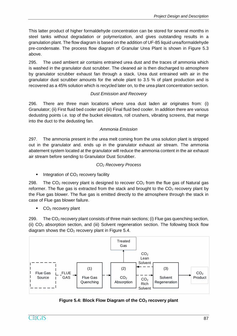
299. The CO2 recovery plant consists of three main sections; (i) Flue gas quenching section,
(ii) CO2 absorption section, and (iii) Solvent regeneration section. The following block flow
diagram shows the CO2 recovery plant in Figure 5.4.
Figure 5.4: Block Flow Diagram of the CO2 recovery plant
Flue Gas
Source
(1)
Flue Gas
Quenching
(2)
CO2
Absorption
(3)
Solvent
Regeneration
CO2
Product
FLUE
GAS
Treated
Gas
CO2
Rich
Solvent
CO2
Lean
Solvent
Project Design and Description
88
Description of Major Components
Land Requirement
300. The area of the proposed project site (battery limit) is about 110 acres including the
existing RMS and excluding the lagoon. The site is partially fallow land on the eastern side of
the existing PUFFL and particularly to the Compressor House having bushes, trees, civil
structures (buildings) and tin shed warehouses exist. Adequate land is available within the
property line of PUFFL. The Project site also includes a small portion of UFFL. About 28 acres
of the lagoon (about 34 acres) will be filled up but not consider in the Project area (110 acres).
No land acquisition will be required for the proposed new fertilizer factory.
Project Layout Including Site Drainage
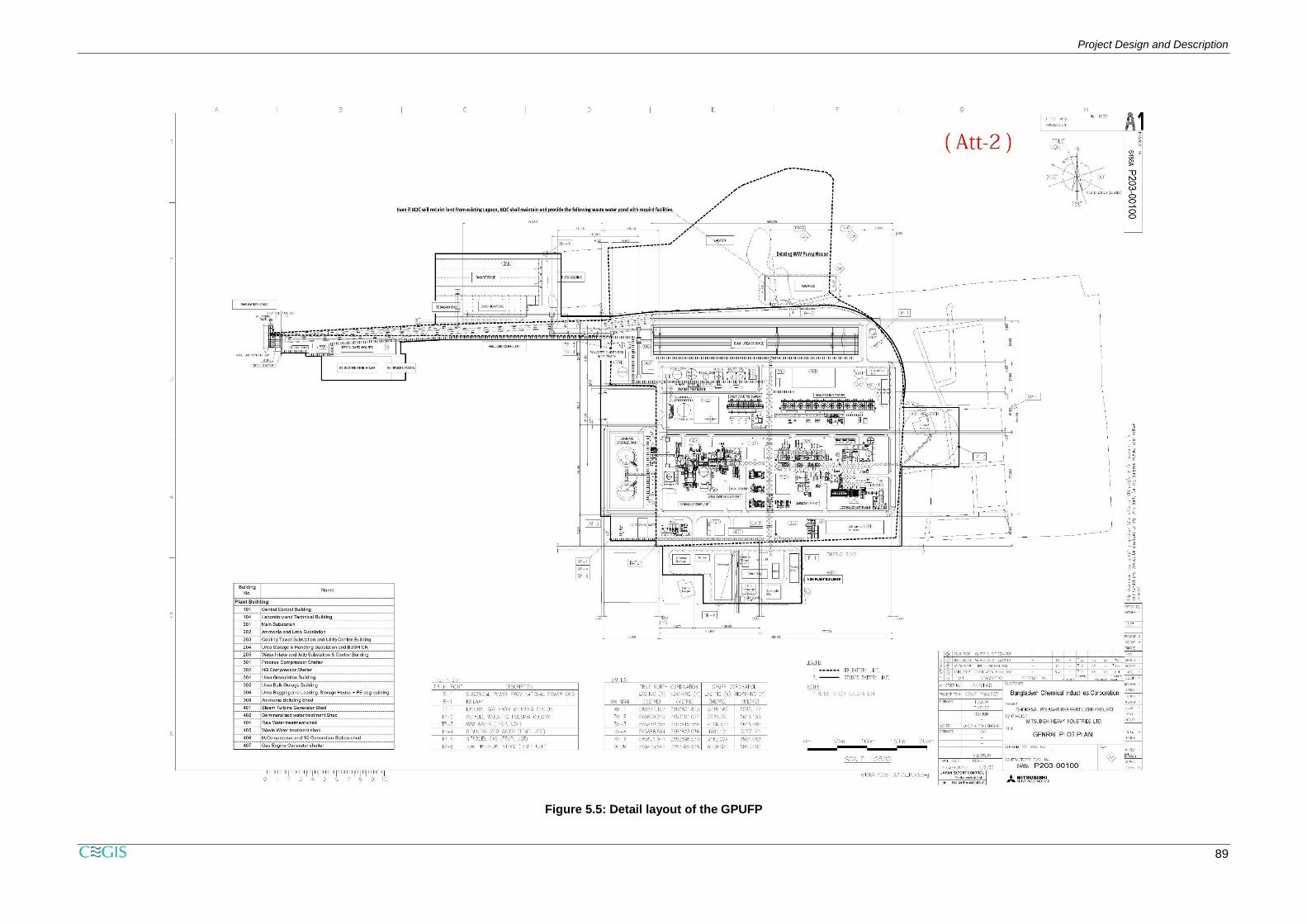
301. The detailed layout plan showing all structures, road network, drainage network,
different pollution abatement measures, waste water and effluent treatment facilities shall be
developed by the EPC contractor before construction. The EPC contractor shall be appointed
after receiving approval of the EIA report from DoE. BCIC shall submit the final layout plan to
DoE for their review and comments considering availability of land, landscape, ground
features, elevation, environmental aspects and social concerns recommended by the EIA
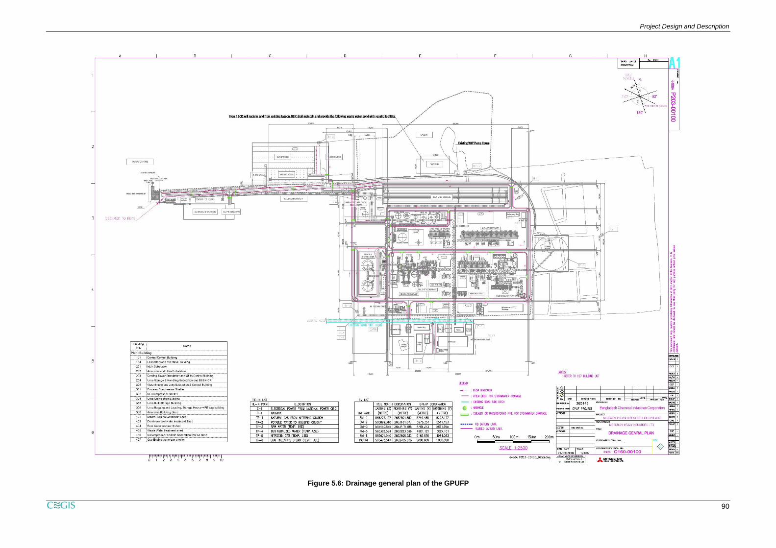
study. However, a preliminary and detail layout plan of the proposed GPUFP project is
presented in Figure 5.5 and drainage general plan is presented in Figure 5.6. The effective
area for the implementation of the given layout plan is about 73 acres, wehereas the Project
area is 110 acres. The EPC contractor will need to show waste storage and sorting areas as
well as a secured disposal location on the layout plan. Given the sensitivity of the demolition
activity, it is recommended that the EPC Contractor is certified on OHSAS 18000. The
Environmental Management Plan (EMP) and the Emergency Preparedness Plan in this report
provides more details in this context.
302. There is an existing drainage network in PUFFL for storm water runoff. Runoff is
collected through open drains and stored in a common basin for sedimentation. The overflow
is then connected with another drain to finally discharge to the condenser cooling water
discharge channel for ultimate disposal to the Shitalakhya River.
303. The run-off drainage network of PUFFL requires improvement with the construction of
the proposed Project as new equipment will be installed and existing structures will be
demolished. Segregation of storm water run-off and cooling water discharge may be required
to avoid possible contamination at the disposal site close to the jetty area. Moreover, it is
recommended to avoid demolition work during the monsoon season.
Project Design and Description
89
Figure 5.5: Detail layout of the GPUFP
Project Design and Description
90
Figure 5.6: Drainage general plan of the GPUFP
Project Design and Description
91
Plant Components of the Layout Plan
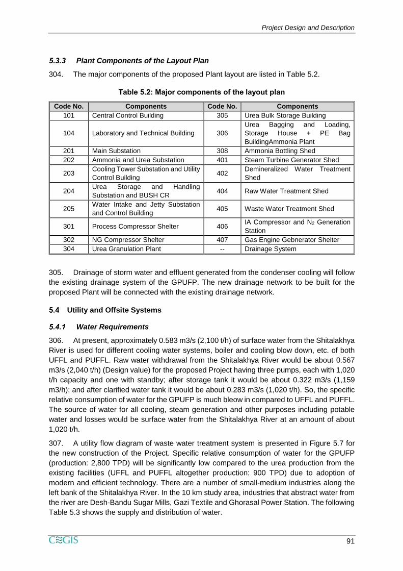
304. The major components of the proposed Plant layout are listed in Table 5.2.
Table 5.2: Major components of the layout plan
Code No. Components Code No. Components
101 Central Control Building 305 Urea Bulk Storage Building
104 Laboratory and Technical Building 306
Urea Bagging and Loading,
Storage House + PE Bag
BuildingAmmonia Plant
201 Main Substation 308 Ammonia Bottling Shed
202 Ammonia and Urea Substation 401 Steam Turbine Generator Shed
203 Cooling Tower Substation and Utility
Control Building 402
Demineralized Water Treatment
Shed
204 Urea Storage and Handling
Substation and BUSH CR 404 Raw Water Treatment Shed
205 Water Intake and Jetty Substation
and Control Building 405 Waste Water Treatment Shed
301 Process Compressor Shelter 406 IA Compressor and N2 Generation
Station
302 NG Compressor Shelter 407 Gas Engine Gebnerator Shelter
304 Urea Granulation Plant -- Drainage System
305. Drainage of storm water and effluent generated from the condenser cooling will follow
the existing drainage system of the GPUFP. The new drainage network to be built for the
proposed Plant will be connected with the existing drainage network.
Utility and Offsite Systems
Water Requirements
306. At present, approximately 0.583 m3/s (2,100 t/h) of surface water from the Shitalakhya
River is used for different cooling water systems, boiler and cooling blow down, etc. of both
UFFL and PUFFL. Raw water withdrawal from the Shitalakhya River would be about 0.567
m3/s (2,040 t/h) (Design value) for the proposed Project having three pumps, each with 1,020
t/h capacity and one with standby; after storage tank it would be about 0.322 m3/s (1,159
m3/h); and after clarified water tank it would be about 0.283 m3/s (1,020 t/h). So, the specific
relative consumption of water for the GPUFP is much bleow in compared to UFFL and PUFFL.
The source of water for all cooling, steam generation and other purposes including potable
water and losses would be surface water from the Shitalakhya River at an amount of about
1,020 t/h.
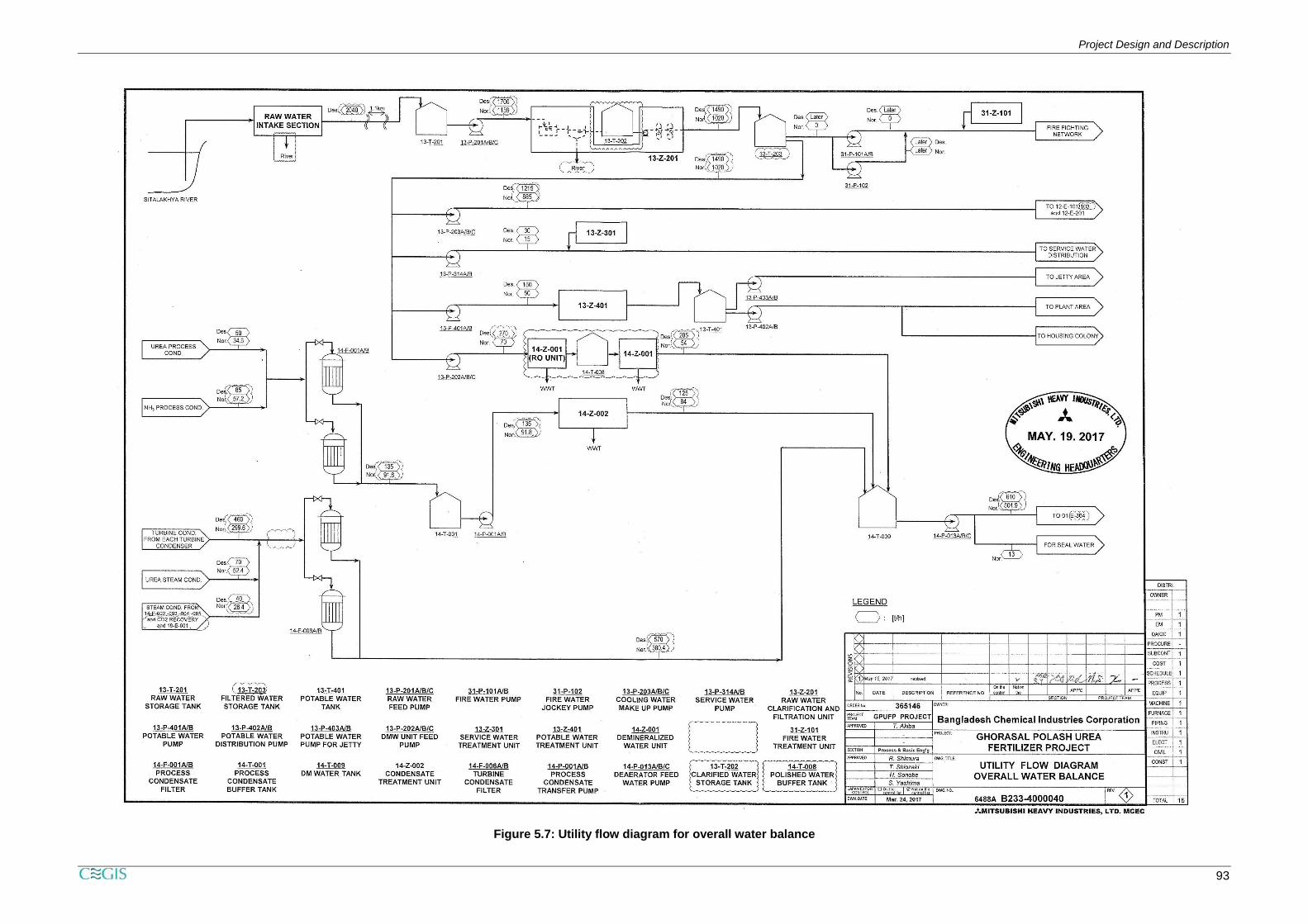
307. A utility flow diagram of waste water treatment system is presented in Figure 5.7 for
the new construction of the Project. Specific relative consumption of water for the GPUFP
(production: 2,800 TPD) will be significantly low compared to the urea production from the
existing facilities (UFFL and PUFFL altogether production: 900 TPD) due to adoption of
modern and efficient technology. There are a number of small-medium industries along the
left bank of the Shitalakhya River. In the 10 km study area, industries that abstract water from
the river are Desh-Bandu Sugar Mills, Gazi Textile and Ghorasal Power Station. The following
Table 5.3 shows the supply and distribution of water.
Project Design and Description
92
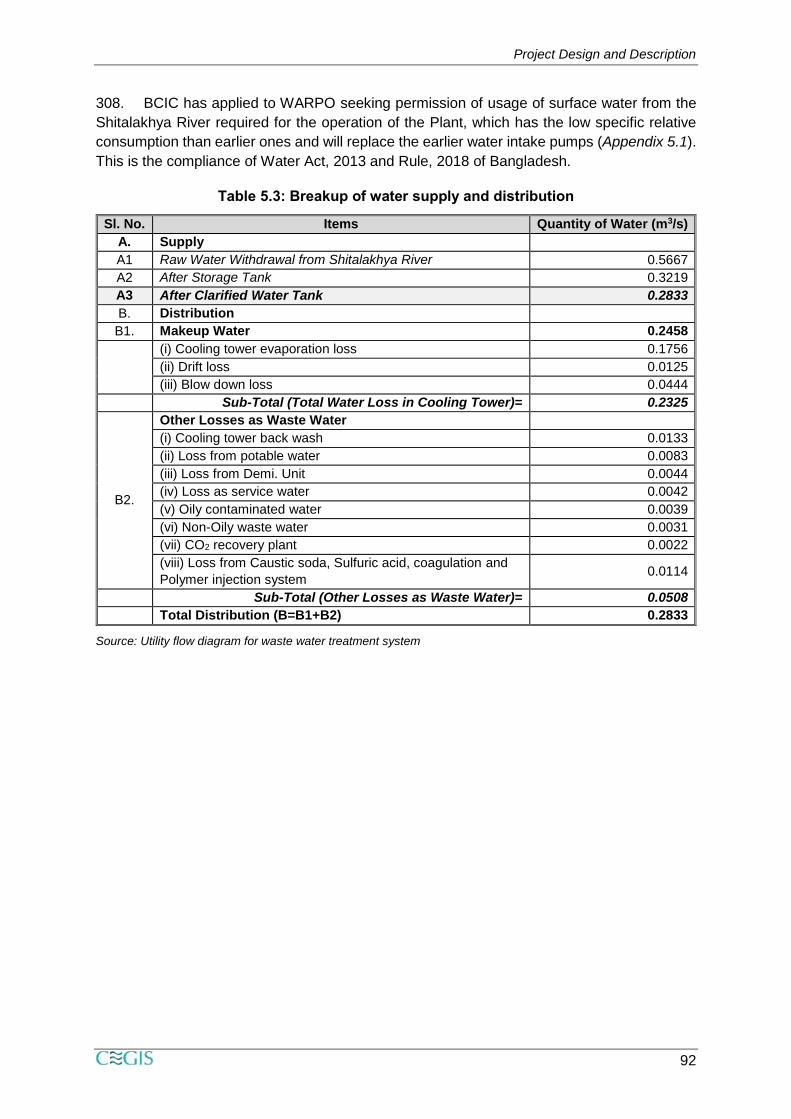
308. BCIC has applied to WARPO seeking permission of usage of surface water from the
Shitalakhya River required for the operation of the Plant, which has the low specific relative
consumption than earlier ones and will replace the earlier water intake pumps (Appendix 5.1).
This is the compliance of Water Act, 2013 and Rule, 2018 of Bangladesh.
Table 5.3: Breakup of water supply and distribution
Sl. No. Items Quantity of Water (m3/s)
A. Supply
A1 Raw Water Withdrawal from Shitalakhya River 0.5667
A2 After Storage Tank 0.3219
A3 After Clarified Water Tank 0.2833
B. Distribution
B1. Makeup Water 0.2458
(i) Cooling tower evaporation loss 0.1756
(ii) Drift loss 0.0125
(iii) Blow down loss 0.0444
Sub-Total (Total Water Loss in Cooling Tower)= 0.2325
B2.
Other Losses as Waste Water
(i) Cooling tower back wash 0.0133
(ii) Loss from potable water 0.0083
(iii) Loss from Demi. Unit 0.0044
(iv) Loss as service water 0.0042
(v) Oily contaminated water 0.0039
(vi) Non-Oily waste water 0.0031
(vii) CO2 recovery plant 0.0022
(viii) Loss from Caustic soda, Sulfuric acid, coagulation and
Polymer injection system 0.0114
Sub-Total (Other Losses as Waste Water)= 0.0508
Total Distribution (B=B1+B2) 0.2833
Source: Utility flow diagram for waste water treatment system
Project Design and Description
93
Figure 5.7: Utility flow diagram for overall water balance

Project Design and Description
94
Project Design and Description
95
Water Intake Pump
The design water intake capacity of each of the three pumps is 1,020 t/h (0.283 m3/s). Among
the three pumps two will be operational and one will be standby. The diameter of each of the
intake pipelines is 350 mm. The mesh sizes of strainers to be installed around the intake mouth
are in the range of 2~10 cm. These design values will be finalized during detail engineering
stage.
Cooling Water System
309. The Project has two cooling water systems which are separated into normal and
essential. Essential cooling water system is connected to essential cooling water pump.
Cooling Tower
310. The Plant will have two cooling towers namely Urea cooling tower and ammonia and
utility cooling tower. Cooling towers are mechanical heat rejection device to remove process
heat and cool the working fluid to near the ambient air temperature. The cooling tower is
counter flow type.
Chemical Injection
311. In order to maintain the required quality of cooling water, the following chemicals are
added separately to each basin of cooling tower:
Sodium Hypochlorite for Biocide Agent
Sulphuric Acid for pH control
Corrosion inhibitor
Scale inhibitor
Microbiological Control Agent (if required)
Make Up Water and Blow Down
312. During continuous operation of cooling tower, circulated water from the cooling tower
system is lost by way of evaporation and drifts which ultimately cause an increasing salinity in
the system. Therefore, to maintain the limit of salinity, a small quantity of water is continuously
drained-off from the discharge header of the circulating water pumps as blow down to waste
water system by manual. Accordingly, all these losses from the system are made up by
continuous feed of raw water to the basin under level control. About 0.102 m3/s (885 t/h) of
surface water will be used as cooling water make-up for two cooling towers with a total of
45,840 m3 water as one time cooling tower filling water.
Side Filtration
313. NormaIIy, around 2% of the circulating water will be filtered from the discharge header
of circulating pumps and circulated back to the basin to remove the suspended solids and
control the limit of total suspended solids in circulating water.
Circulation
314. Ammonia, Utility and Offsite unit circulation is established by two steam turbine driven
pumps and two motor driven pumps. One motor driven pump shall be kept as stand-by for
auto-start. Urea unit has two motor driven circulating pumps, out of which one shall be kept
as stand-by for auto-start.
Project Design and Description
96
Priority Supply
315. Considering the need of uninterrupted supply of cooling water for some critical
equipment/ exchangers, a separate priority header, which is called essential cooling water
line. This essential cooling water header (ECW) feeds to following 'equipment mainly:
316. For Ammonia Plant
Blow Down Cooler
Critical Oil Coolers
317. For Urea Plant
Seal Water Coolers
Flushing Condensate Cooler
Critical Oil Coolers
318. For Utility and Offsite Facilities
Auxiliary Boiler Blow Down Cooler
Ammonia Storage Refrigeration Unit
Instrument Air Compressor
Critical Oil Coolers
a) System Performance
Ammonia, Utility and Offsite Cooling Water System
Circulation Capacity: Design 42,000 t/h; Normal 34,802 t/h
Temperature: Supply Max. 33°C; Return Max. 43°C
Urea Cooling Water System
Circulation Capacity: Design 9,500 t/h; Normal 7,592 t/h
Temperature: Supply Max. 33°C; Return Max. 43°C
b) Equipment Performance
For Ammonia. Utility and Offsite Cooling Water System
Cooling Tower: One set with counter flow type
Cooling Water Circulation Pump: 3 running+1 stand-by with rated capacity of
14, 100 m3/h each·
For Essential Cooling Water System
Essential Cooling Water Circulation Pump: 1 running+1 stand-by with rated
capacity of 2,900 m3/h each
For Urea Cooling Water System
Cooling Tower: One set with counter flow type
Cooling Water Circulation Pump: 1 running+1 stand-by with rated capacity of
9,700 m3/h each·
Project Design and Description
97
Raw Water Treatment System
Raw Water System
319. Raw Water Intake facilities are located on the left bank of the Shitalakhya River. The
raw water is pumped to settling basins located in the Jetty area and transferred to the Raw
Water Storage Tank through the pipeline of about 1.1 km long.
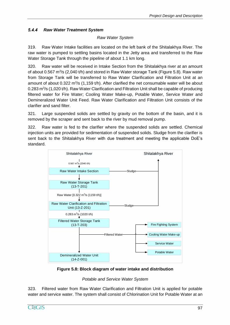
320. Raw water will be received in Intake Section from the Shitalakhya river at an amount
of about 0.567 m3/s (2,040 t/h) and stored in Raw Water storage Tank (Figure 5.8). Raw water
from Storage Tank will be transferred to Raw Water Clarification and Filtration Unit at an
amount of about 0.322 m3/s (1,159 t/h). After clarified the net consumable water will be about
0.283 m3/s (1,020 t/h). Raw Water Clarification and Filtration Unit shall be capable of producing
filtered water for Fire Water; Cooling Water Make-up, Potable Water, Service Water and
Demineralized Water Unit Feed. Raw Water Clarification and Filtration Unit consists of the
clarifier and sand filter.
321. Large suspended solids are settled by gravity on the bottom of the basin, and it is
removed by the scraper and sent back to the river by mud removal pump.
322. Raw water is fed to the clarifier where the suspended solids are settled. Chemical
injection units are provided for sedimentation of suspended solids. Sludge from the clarifier is
sent back to the Shitalakhya River with due treatment and meeting the applicable DoE’s
standard.
Figure 5.8: Block diagram of water intake and distribution
Potable and Service Water System
323. Filtered water from Raw Water Clarification and Filtration Unit is applied for potable
water and service water. The system shall consist of Chlorination Unit for Potable Water at an
Shitalakhya River
Raw Water Intake Section
Raw Water Storage Tank
(13-T-201)
Raw Water Clarification and Filtration
Unit (13-Z-201)
Shitalakhya River
0.567 m3/s (2040 t/h)
Raw Water [0.322 m3/s (1159 t/h)]
Sludge
Sludge
Filtered Water Storage Tank
(13-T-203)
Demineralized Water Unit
(14-Z-001)
0.283 m3/s (1020 t/h)
Fire Fighting System
Cooling Water Make-up
Service Water
Potable Water
Filtered Water
Project Design and Description
98
amount of about 0.0417 m3/s (150 t/h). The system shall consist of Service Water Treatment
Unit with the capacity of at least 0.0083 m3/s (30 t/h).
Demineralized Water and Condensate Treatment
324. The Demineralized Water Unit consists of the Reverse Osmosis (RO) system and ion
exchanger. Filtered water in filter water storage tank is fed to the Reverse Osmosis (RO)
system and ion exchangers in the Demineralized Water Unit for demineralization. The
Condensate Treatment Unit consists of the ion exchangers. The sources of condensate are:
(i) Stripped process condensate from the Ammonia Plant; and (ii) Stripped process
condensate from the Urea Plant. The source of demi water is filtered water from Raw Water
Clarification and Filtration Unit.
325. Effluent from the neutralization pit for Demineralized Water Unit is transferred by
neutralization pump and fed to the Waste Water Treatment System (WWTS) at an amount of
at least 0.0569 m3/s [205 t/h (outlet)].
326. The regeneration stage of the ion exchangers receives chemicals from the sulphuric
acid and caustic soda distribution system and injects chemical at the regeneration.
327. Spent regenerant, blowdown and waste water from the Condensate Treatment Unit
are discharged into the neutralization pit for the Condensate Treatment Unit lined with
chemical resistant material. Air for the polishing unit and neutralization pit is supplied by the
mixing air blower for Condensate Treatment Unit.
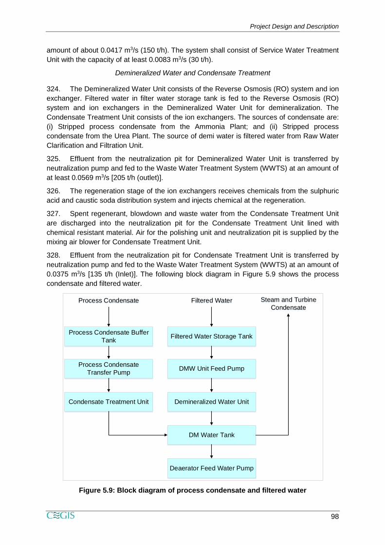
328. Effluent from the neutralization pit for Condensate Treatment Unit is transferred by
neutralization pump and fed to the Waste Water Treatment System (WWTS) at an amount of
0.0375 m3/s [135 t/h (Inlet)]. The following block diagram in Figure 5.9 shows the process
condensate and filtered water.
Figure 5.9: Block diagram of process condensate and filtered water
Process Condensate Filtered Water Steam and Turbine
Condensate
Process Condensate Buffer
TankFiltered Water Storage Tank
Process Condensate
Transfer PumpDMW Unit Feed Pump
Condensate Treatment Unit Demineralized Water Unit
DM Water Tank
Deaerator Feed Water Pump
Project Design and Description
99
Boiler Feed Water System
329. The chosen boiler water treatment program will be All Volatile Treatment (AVT) using
volatile oxygen scavenger (Hydrazine) and neutralizing amine (Ammonia).
Steam Generation System
330. The Steam Turbine Generator is condensing type. In normal operation, all steam
generated in the Ammonia Plant, and Auxiliary Boiler is self-balanced without any venting.
Auxiliary Boiler has a remote automatic control, combustion safeguards with flame detection
and sampling and analyzer system for supervising the steam and boiler water quality and flue
gas components.
Electric Power Generation System
331. The Project has provisioned captive power for day-to-day use. For this, two units of
Steam Turbine Generator (STG) of 32 MW each and One unit of Gas Engine Generator (GEG)
of 9 MW capacity. The STG will supply power to the entire plant while GEG will supply power
for start-up of Auxiliary Boiler and Steam Turbine Generator. The STG will be operated in half
load condition.
Natural Gas and Fuel Gas System
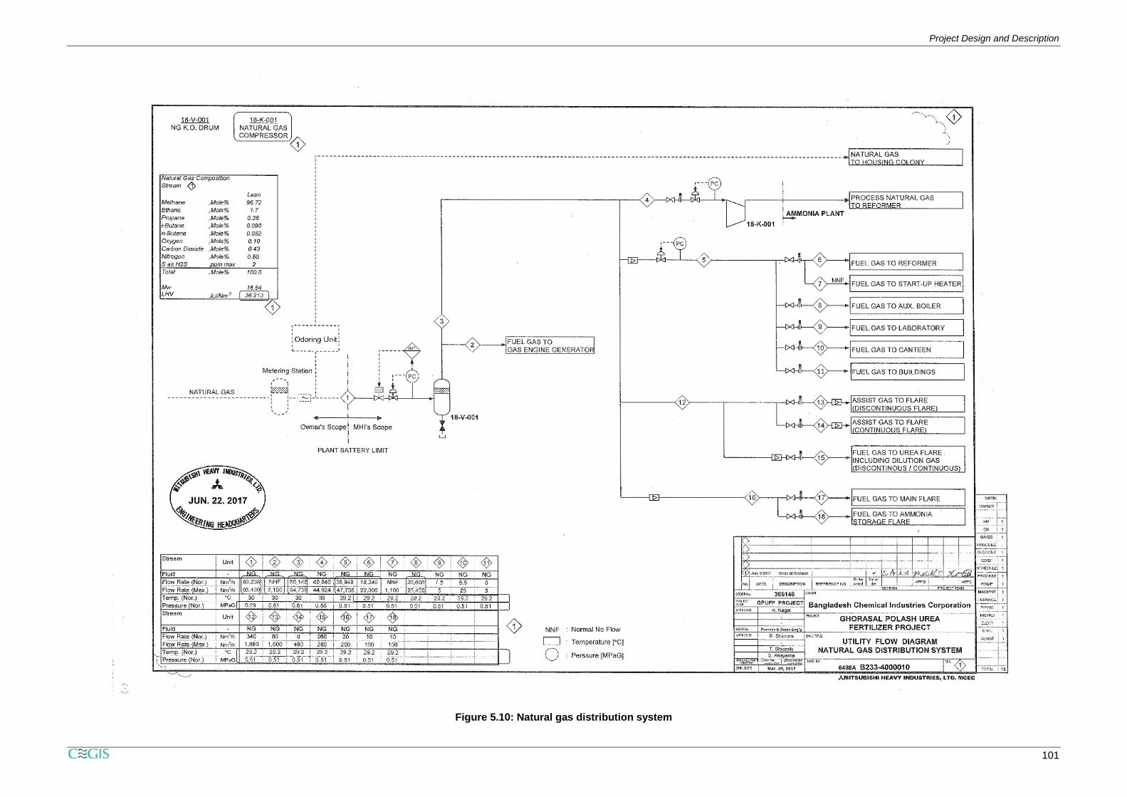
332. Natural gas is used for the process feed and fuel for GPUFP Project. Natural gas is
supplied through the incoming line from the battery limit of the plant. The pressure ranges from
0.69-0.98 MPaG. Natural Gas has two functions, e.g., process natural gas and fuel natural
gas. The natural gas is distributed as process gas and fuel gas to the users of the followings:
Process natural gas
to Primary Reformer of Ammonia Plant.
Fuel gas (0.505 MPaG)
to Primary Reformer of Ammonia Plant
to Start-up Heater of Ammonia Plant
to Auxiliary Boiler
to Gas Engine Generator
to Laboratory
to Canteen
to Building.
to Main Flare Stack
to Ammonia Storage Flare Stack
to Continuous Urea Flare
to Discontinuous Urea Flare.
333. During the normal operation, quantity of blow-out gases is zero or very small. In case
of upset conditions and/ or start-up and shut down operations of the facilities, large quantity of
blow-out gases is vented. It is sent to Vent Stack located in Ammonia Plant and vented to
atmosphere without burning. The natural gas distribution system along with in and out is
shown in the utility flow diagram in Figure 5.10.

Project Design and Description
100
Project Design and Description
101
Figure 5.10: Natural gas distribution system
Project Design and Description
102
Project Design and Description
103
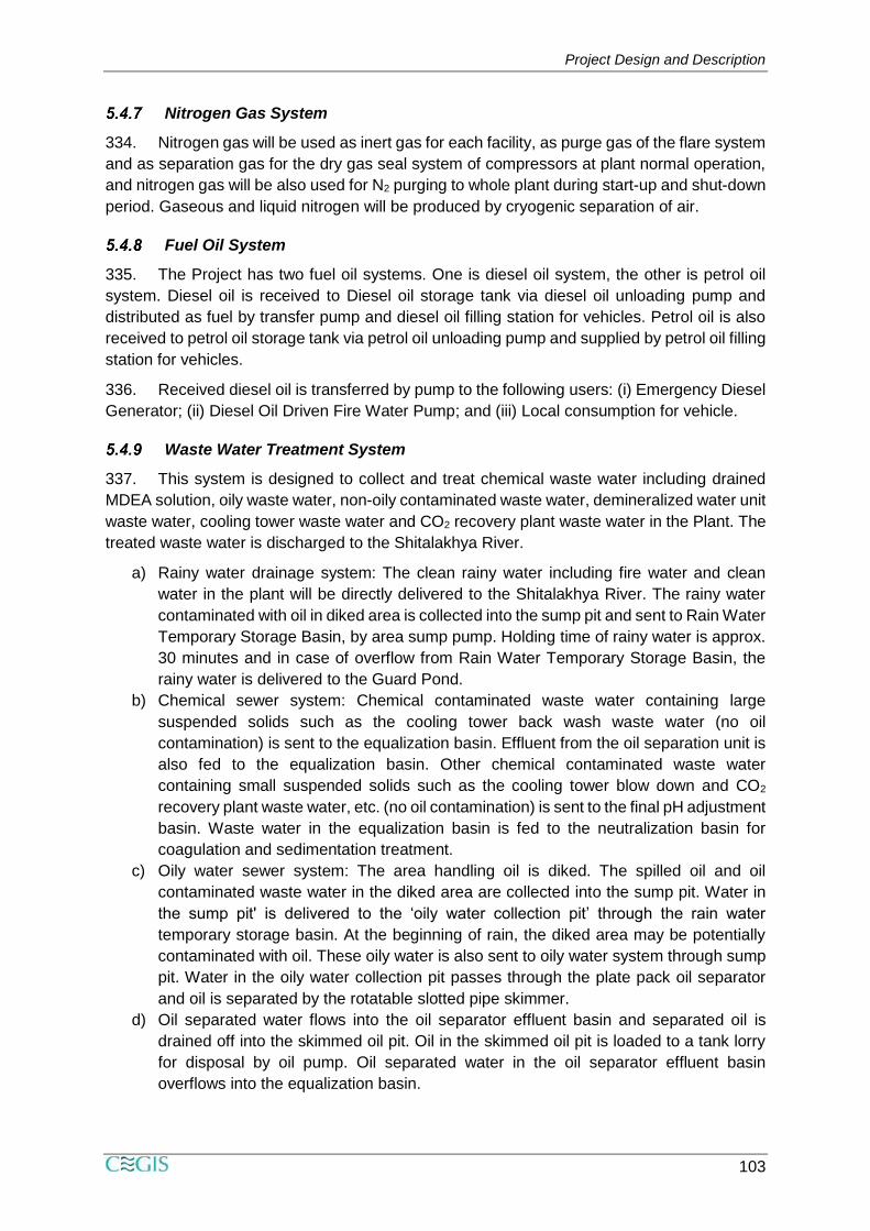
Nitrogen Gas System
334. Nitrogen gas will be used as inert gas for each facility, as purge gas of the flare system
and as separation gas for the dry gas seal system of compressors at plant normal operation,
and nitrogen gas will be also used for N2 purging to whole plant during start-up and shut-down
period. Gaseous and liquid nitrogen will be produced by cryogenic separation of air.
Fuel Oil System
335. The Project has two fuel oil systems. One is diesel oil system, the other is petrol oil
system. Diesel oil is received to Diesel oil storage tank via diesel oil unloading pump and
distributed as fuel by transfer pump and diesel oil filling station for vehicles. Petrol oil is also
received to petrol oil storage tank via petrol oil unloading pump and supplied by petrol oil filling
station for vehicles.
336. Received diesel oil is transferred by pump to the following users: (i) Emergency Diesel
Generator; (ii) Diesel Oil Driven Fire Water Pump; and (iii) Local consumption for vehicle.
Waste Water Treatment System
337. This system is designed to collect and treat chemical waste water including drained
MDEA solution, oily waste water, non-oily contaminated waste water, demineralized water unit
waste water, cooling tower waste water and CO2 recovery plant waste water in the Plant. The
treated waste water is discharged to the Shitalakhya River.
a) Rainy water drainage system: The clean rainy water including fire water and clean
water in the plant will be directly delivered to the Shitalakhya River. The rainy water
contaminated with oil in diked area is collected into the sump pit and sent to Rain Water
Temporary Storage Basin, by area sump pump. Holding time of rainy water is approx.
30 minutes and in case of overflow from Rain Water Temporary Storage Basin, the
rainy water is delivered to the Guard Pond.
b) Chemical sewer system: Chemical contaminated waste water containing large
suspended solids such as the cooling tower back wash waste water (no oil
contamination) is sent to the equalization basin. Effluent from the oil separation unit is
also fed to the equalization basin. Other chemical contaminated waste water
containing small suspended solids such as the cooling tower blow down and CO2
recovery plant waste water, etc. (no oil contamination) is sent to the final pH adjustment
basin. Waste water in the equalization basin is fed to the neutralization basin for
coagulation and sedimentation treatment.
c) Oily water sewer system: The area handling oil is diked. The spilled oil and oil
contaminated waste water in the diked area are collected into the sump pit. Water in
the sump pit' is delivered to the ‘oily water collection pit’ through the rain water
temporary storage basin. At the beginning of rain, the diked area may be potentially
contaminated with oil. These oily water is also sent to oily water system through sump
pit. Water in the oily water collection pit passes through the plate pack oil separator
and oil is separated by the rotatable slotted pipe skimmer.
d) Oil separated water flows into the oil separator effluent basin and separated oil is
drained off into the skimmed oil pit. Oil in the skimmed oil pit is loaded to a tank lorry
for disposal by oil pump. Oil separated water in the oil separator effluent basin
overflows into the equalization basin.
Project Design and Description
104
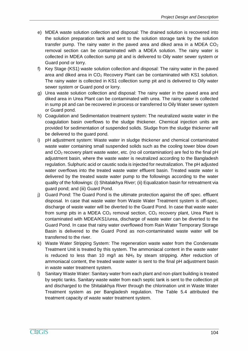
e) MDEA waste solution collection and disposal: The drained solution is recovered into
the solution preparation tank and sent to the solution storage tank by the solution
transfer pump. The rainy water in the paved area and diked area in a MDEA CO2
removal section can be contaminated with a MDEA solution. The rainy water is
collected in MDEA collection sump pit and is delivered to Oily water sewer system or
Guard pond or lorry.
f) Key Stage (KS1) waste solution collection and disposal: The rainy water in the paved
area and diked area in CO2 Recovery Plant can be contaminated with KS1 solution.
The rainy water is collected in KS1 collection sump pit and is delivered to Oily water
sewer system or Guard pond or lorry.
g) Urea waste solution collection and disposal: The rainy water in the paved area and
diked area in Urea Plant can be contaminated with urea. The rainy water is collected
in sump pit and can be recovered in process or transferred to Oily Water sewer system
or Guard pond.
h) Coagulation and Sedimentation treatment system: The neutralized waste water in the
coagulation basin overflows to the sludge thickener. Chemical injection units are
provided for sedimentation of suspended solids. Sludge from the sludge thickener will
be delivered to the guard pond.
i) pH adjustment system: Waste water in sludge thickener and chemical contaminated
waste water containing small suspended solids such as the cooling tower blow down
and CO2 recovery plant waste water, etc. (no oil contamination) are fed to the final pH
adjustment basin, where the waste water is neutralized according to the Bangladesh
regulation. Sulphuric acid or caustic soda is injected for neutralization. The pH adjusted
water overflows into the treated waste water effluent basin. Treated waste water is
delivered by the treated waste water pump to the followings according to the water
quality of the followings: (i) Shitalakhya River; (ii) Equalization basin for retreatment via
guard pond; and (iii) Guard Pond.
j) Guard Pond: The Guard Pond is the ultimate protection against the off spec. effluent
disposal. In case that waste water from Waste Water Treatment system is off-spec,
discharge of waste water will be diverted to the Guard Pond. In case that waste water
from sump pits in a MDEA CO2 removal section, CO2 recovery plant, Urea Plant is
contaminated with MDEA/KS1/urea, discharge of waste water can be diverted to the
Guard Pond. In case that rainy water overflowed from Rain Water Temporary Storage
Basin is delivered to the Guard Pond as non-contaminated waste water will be
transferred to the river.
k) Waste Water Stripping System: The regeneration waste water from the Condensate
Treatment Unit is treated by this system. The ammoniacal content in the waste water
is reduced to less than 10 mg/I as NH3 by steam stripping. After reduction of
ammoniacal content, the treated waste water is sent to the final pH adjustment basin
in waste water treatment system.
l) Sanitary Waste Water: Sanitary water from each plant and non-plant building is treated
by septic tanks. Sanitary waste water from each septic tank is sent to the collection pit
and discharged to the Shitalakhya River through the chlorination unit in Waste Water
Treatment system as per Bangladesh regulation. The Table 5.4 attributed the
treatment capacity of waste water treatment system.
Project Design and Description
105
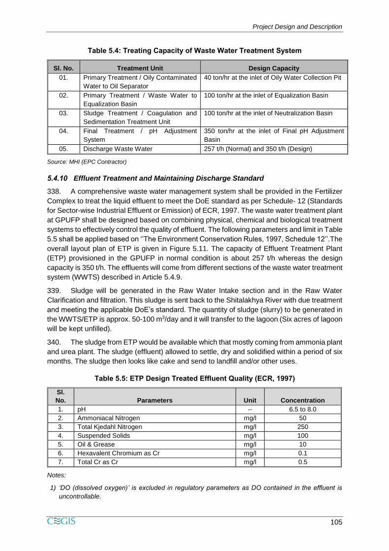
Table 5.4: Treating Capacity of Waste Water Treatment System
Sl. No. Treatment Unit Design Capacity
01. Primary Treatment / Oily Contaminated
Water to Oil Separator
40 ton/hr at the inlet of Oily Water Collection Pit
02. Primary Treatment / Waste Water to
Equalization Basin
100 ton/hr at the inlet of Equalization Basin
03. Sludge Treatment / Coagulation and
Sedimentation Treatment Unit
100 ton/hr at the inlet of Neutralization Basin
04. Final Treatment / pH Adjustment
System
350 ton/hr at the inlet of Final pH Adjustment
Basin
05. Discharge Waste Water 257 t/h (Normal) and 350 t/h (Design)
Source: MHI (EPC Contractor)
Effluent Treatment and Maintaining Discharge Standard
338. A comprehensive waste water management system shall be provided in the Fertilizer
Complex to treat the liquid effluent to meet the DoE standard as per Schedule- 12 (Standards
for Sector-wise Industrial Effluent or Emission) of ECR, 1997. The waste water treatment plant
at GPUFP shall be designed based on combining physical, chemical and biological treatment
systems to effectively control the quality of effluent. The following parameters and limit in Table
5.5 shall be applied based on ‘’The Environment Conservation Rules, 1997, Schedule 12’’.The
overall layout plan of ETP is given in Figure 5.11. The capacity of Effluent Treatment Plant
(ETP) provisioned in the GPUFP in normal condition is about 257 t/h whereas the design
capacity is 350 t/h. The effluents will come from different sections of the waste water treatment
system (WWTS) described in Article 5.4.9.
339. Sludge will be generated in the Raw Water Intake section and in the Raw Water
Clarification and filtration. This sludge is sent back to the Shitalakhya River with due treatment
and meeting the applicable DoE’s standard. The quantity of sludge (slurry) to be generated in
the WWTS/ETP is approx. 50-100 m3/day and it will transfer to the lagoon (Six acres of lagoon
will be kept unfilled).
340. The sludge from ETP would be available which that mostly coming from ammonia plant
and urea plant. The sludge (effluent) allowed to settle, dry and solidified within a period of six
months. The sludge then looks like cake and send to landfill and/or other uses.
Table 5.5: ETP Design Treated Effluent Quality (ECR, 1997)
Sl.
No. Parameters Unit Concentration
1. pH -- 6.5 to 8.0
2. Ammoniacal Nitrogen mg/l 50
3. Total Kjedahl Nitrogen mg/l 250
4. Suspended Solids mg/l 100
5. Oil & Grease mg/l 10
6. Hexavalent Chromium as Cr mg/l 0.1
7. Total Cr as Cr mg/l 0.5
Notes:
1) ‘DO (dissolved oxygen)’ is excluded in regulatory parameters as DO contained in the effluent is
uncontrollable.
Project Design and Description
106
2) ‘Radioactive materials’ are excluded in regulatory parameters as no radioactive materials are
contained in raw river water and produced in ammonia and urea production processes.
3) Following inorganic parameters are not included in raw river water quality analysis records. The
effluent limits of these parameters will comply with the above-mentioned regulation, provided that
no substances of these parameters are contained in the raw river water.
- Total Chromium and Chromium Hexavalent
4) The effluent from Raw Water Intake Unit, Raw Water Treatment Unit and their related facilities will
be discharged directly to river without any treatment and the above-mentioned regulations are not
applied for those effluents.
5) When water quality at the battery limit for effluent discharge from Waste Water Treatment Unit to
river is deviated from any regulatory parameters due to any factors such as plant upset condition
and/or undesirable raw river water quality, the water will be discharged to existing Lagoon (out of
Contractor’s scope). If Owner will discharge any effluent from existing Lagoon (out of Contractor’s
scope) to river, Owner shall control water quality based on the above-mentioned regulation. Each
parameter of those effluent water qualities is excluded in regulatory parameters for Contractor’s
scope due to outside battery limit.