Embed Size (px)
Citation preview

AIAA Orange County Section
Student Launch Initiative 2010-2011
Project M1 Quantification of the effects of acceleration
on hard disk drive latency
Submitted by: AIAA Orange County Section
NASA Student Launch Initiative Team Orange County, CA
Submitted to:
Marshall Space Flight Center Huntsville, Alabama
September 27, 2010
Image From: XPRS.ORG
Project Manager
Sjoen Koepke 20162 E Santiago Canyon Orange, California 92869
(714) 288-0321

2
Table of Contents
1.0 Organization Information 3 1.1 AIAA information 3 1.2 Name of Organization and Title of project 3 1.3 Name of administrative staff member 3 1.4 Mentors 3 1.5 Advisors 4 1.6 Student Participants and Responsibilities 5 1.7 NAR Section for launch assistance, mentoring, reviewing 72.0 Facilities and Equipment 7 2.1 Description of facilities 7 2.2 Necessary Personnel 8 2.3 Computer Equipment 8 2.4 Implementation of Architectural and … Compliance for IT 93.0 Safety 10 3.1 Level 2 and/or Level 3 mentor 10 3.2 Written safety plan 10 3.3 Evidence of awareness of laws regarding unmanned launches 10 3.4 Written statement that all members understand/follow rules 124.0 Technical Requirements 12 4.1 Vehicle design and dimensions 12 4.2 Preparation and launch 13 4.3 Recovery Electronics 14 4.4 Motor type and design 14 4.5 Science Payload 15 4.6 Requirements for rocket and payload 15 4.7 Testing 16 4.8 Major challenges and solutions 175.0 Educational Engagements 17 5.1 Written plan for soliciting additional community support 17 5.2 Educational projects engaging 75 or more younger students 186.0 Project Plan 18 6.1 Curriculum framework – local standards 18 6.2 Curriculum framework – national standards 18Appendix A NAR and TRA Safety Rule Summary and Compliance 20Appendix B Launch Safety Rules - AIAA OC Section (including SLI) 27Appendix C Shop Safety Rules – AIAA OC Section (including SLI) 30Appendix D Hazardous Material Safety Rules – AIAA OC Section (inc SLI) 32Appendix E Project Timeline 41Appendix F Project Budget 42Appendix G Requirements cross reference 43

3
1. Organization Information
1.1. AIAA Information The American Institute of Aeronautics and Astronautics is the professional society for the field of Aerospace Engineering. Our SLI team is sponsored by the Orange County section in California. The board meets on the first Tuesday of every month. In their educational outreach, they provide professional guidance and assistance to youth who wish to pursue projects related to aerospace. The organization of the board of the Orange County section is as follows:
Chair James Martin (Adviser to SLI) Chair Elect Kimberly Castro Treasurer Philip Ridout Secretary Ronald Freeman Technical Jeff Norton Honors & Awards Igor Jaremenko Programs Bob Welge Membership Tobenette Holtz Young Professionals Eldred Magner Communications Enrique Castro At Large Bob Koepke (Mentors to SLI) At Large Jann Koepke (Mentors to SLI) Public Policy Kemal Shweyk Education John Rose Past Chair Dino Roman
1.2. Name of organization and title of project AIAA Orange County Section Student Launch Initiative team is composed of students from several high schools in Orange County, California under the direction of the American Institute of Aeronautics and Astronautics Orange County Section. The project, entitled “M1: Quantification of the effects of acceleration on hard disk drive latency” studies and quantifies the effects of acceleration on hard disk drive latency. 1.3. Name of administrative staff member (team official) Administrative staff members serving as the Team Officials and mentors are Robert Koepke and Janet Koepke. Contact information:
20162 E Santiago Canyon Orange, CA 92869 (714) 288-0321 [email protected]
1.4. Mentors (will attend many meetings and launches, directing the team) 1.4.1. Robert Koepke (Electrical Engineer, Programmer, Level 2 NAR) Robert has been co-leading TARC teams for 3 years and 4H rocketry projects for 12 years. He has a BS degree in Electrical Engineering from USC and has worked as an electronics designer, programmer, and now a director of the software department doing embedded programming for thermal printers. Robert worked on the F-20 Tigershark while at Northrop. Robert launched his first rockets shortly after Sputnik in 1957 and has continued in rocketry with his own children and grandchildren, Indian Princesses and Indian Guides, and 4H. 1.4.2. Jann Koepke (Artist, Mom, Level 1 NAR) Jann has been co-leading TARC teams for 3 years and 4H rocketry projects for 10 years. She has a bachelor’s degree in Fine Arts from Cal State University Los
4
Angeles in 1979. She has worked in electronic business as an assembler and in the accounting office. Now she is retired. She has been doing Rocketry for 25 years with her husband children and grandchildren. She has been in 4-H for 11 years and has been doing rocketry in 4-H for 10 years. She has also led 4H projects in livestock including lambs, goats, and beef. 1.4.3. Brendan Clarke (Aerospace Engineering major, Level 1 NAR) Brendan is 18 years old and was in rocketry in 4H for 8 years. He was on the TARC team for 3 years and Project Manger the last year. Last year Brendan graduated from El Modena high school and is now majoring in Aeronautical Engineering at Cal Poly Pomona. 1.4.4. Michael Stoop (Software Engineer, Level 3 NAR, California Pyro 3) Mike Stoop is currently the CTO of PriceDoc, Inc, a healthcare related web services company. Mike has been in the software industry for 30 years and an avid rocketeer for 40 years. Mike achieved his level 3 certification in 2002 and has participated in many individual and team 'M" class and above rocket projects. Mike is also the owner of Madcow Rocketry, a mid/high power rocket kit manufacturer.
1.5. Advisors (available for questions and help in problem solving in their area of expertise)
1.5.1. Dr. James Martin Dr. Martin holds degrees from West Virginia University, Massachusetts Institute of Technology, and George Washington University. He has worked at the NASA Langley Research Center, The University of Alabama, and Boeing. His work has mostly involved the design and evaluation of reusable launch vehicles. Some recent work has been on crew escape for the Shuttle, the Space Launch Initiative, and a robotic lander on the moon. Dr. Martin retired from Boeing when the Launch vehicle business was sold. He continues to be active in aerospace doing consulting, as an Associate Editor for AIAA J. Spacecraft and Rockets, and as Chair of the local AIAA Orange County Section. 1.5.2. Jonathan Mack (Electrical Engineer and Programmer) Jonathan graduated with a Bachelor of Science from Long Beach State. Currently he is an electronics design engineer involved in hardware and software development including diverse fields such as toys, audio, and currently printing. He has led a 4H project in mechanical, electrical and software design areas in robotics. At home his hobbies mainly focus on improving DIY (Do It Yourself) knowledge, including everything from mad science projects to more mundane things like welding and cooking (usually not at the same time.) 1.5.3. Guy Heaton (Mechanical Engineer) Guy graduated with a Bachelor of Science from Pepperdine University. Currently he is a Senior Mechanical Engineer and has been working on printing solutions for 12 years. Responsibilities include designing for injection and blow molding and extrusions. He also does mechanical systems, drive trains, cabling, durability testing, and sheet metal design. When not designing new printers he does manufacturing time analysis, line balancing, and documentation 1.5.4. Khoa Le (Mechanical Engineer) Khoa graduated with a BS in Mechanical Engineering and is working on his Masters in Mechanical Engineering emphasizing Design and Materials for

5
Manufacturing with a minor emphasis on Automated Manufacturing. Currently he is a Mechanical Design Engineer and conducts structural analysis for other engineers within the department. As a Mechanical Design Engineer, he designs and evaluates mechanical components, based upon theory using finite element analysis and core Mechanical Engineering concepts. 1.5.5. Michael Updegraff (Software Engineer, Level 2 NAR) Michael Updegraff is the Sr. Principal Engineer at PriceDoc.com. Michael has been involved in web application development for 15 years working alongside Google’s engineers in Public API (Application Programming Interface – a common defined interface between software modules) consumption. Michael holds a level 2 NAR certification and participates in FAR (Friends of Amateur Rocketry is a licensed non-profit organization dedicated to experimental rocketry) experimental launches in the Mojave Desert. 1.5.6. Doug Jacobs (Fiberglassing) Doug Jacobs is the person at West Marine in Orange, CA that is very familiar with fiber glassing using the West System. He will conduct a training session about using the West Marine system, at the store, for the benefit of team members. In addition, he is available for questions
1.6. Student Participants and responsibilities
All student members in the team are listed below. These members will be responsible for completing all of the work (e.g. written documents, presentations, design, construction, and launching) using mentors and advisors only for guidance. Team members represent four high schools in Orange County. 1.6.1. Sjoen (Program Manager - Recovery) Sjoen is a junior at El Modena High School in Orange. She is in Pre Calculus /Trig, Physiology and U.S. History and has a GPA of 3.57. She has been in TARC for three years, rocketry for ten years, and has helped out her parents with numerous rocketry projects, which taught interested youth Rocketry and Engineering. She raises and shows lambs and is interested in becoming a business major in college. Sjoen holds a level 1 Junior NAR certification 1.6.2. Mika (Propulsion - Web Site) Mika is a sophomore and is enrolled at El Modena High School in Orange and has been in rocketry for six years and in TARC for three years. He has a GPA of 4.15 and is taking Algebra II H, AP Biology, AP World History, and has participated in the MESA Program (Mathematics, Engineering, Science, Achievement) and got 5th place for a pentathlon. He is also a cross-country and track runner for El Modena. Mika holds a level 1 Junior NAR certification. 1.6.3. Mohan (Payload - Web Site) Mohan is a sophomore currently attending Trabuco Hills High School in Mission Viejo, California. He has a GPA of 4.6 and is currently enrolled in Honors Physics, Honors Pre-Calculus, and AP Biology. He plays the piano, violin, and tabla (an Indian percussion instrument) and is active in several clubs in his school, such as MUN (Model United Nations), OCAD (Orange County Academic Decathlon), and FBLA (Future Business Leaders of America). 1.6.4. Justin (Budget - Recovery - Web Site) Justin is a junior at Sunny Hills High School in Fullerton, CA, ending his sophomore year with a weighted GPA of 4.0. He is enrolled in AP Physics, AP

6
Calculus AB, Honors 3 English, US History, Spanish 3 Honors, and AP World History. Although he has never participated in an engineering project, he does have a knack for building things. In his free time, he spends his time training for archery for an upcoming tournament. 1.6.5. Insang (Recovery) Insang is a Junior at Sunny Hills High School in Fullerton, CA. He is currently enrolled in AP Calculus, AP Physics, and AP Chemistry. He is very interested in Aerospace engineering, especially rockets. Insang has been in the United States for nearly 3 years. 1.6.6. Julia (Fundraising) Julia is a senior attending Sunny Hills High School in Fullerton, California. She has a weighted GPA of 4.7 and is currently enrolled in AP Calculus BC, AP Physics B, AP Literature and Composition, AP Micro/Macro Economics, AP Spanish, and Intro to Business. She has involved herself in several student-organizations such as JSA (Junior Statesmen of America), FBLA (Future Business Leaders of America), and OCAD (Orange County Academic Decathlon) and received 3rd place for Chemistry in Division I. Although this is her first time in an engineering project, she hopes to utilize her interest in science and managerial skills and contribute to the project. 1.6.7. Daniel (Crew) Daniel is a senior at Sunny Hills High School. He is taking AP Physics, AP Calculus BC, AP English Literature, Economics, Principles of Engineering, and Auto CAD. He finished his junior year with a 4.5 weighted GPA. He loves playing the guitar, playing the drums, and singing. His biggest academic strength is math, and, although he has not participated in any project like this one, his dream is to attend Cal Tech and become a successful engineer. 1.6.8. Jean-Paul (Outreach - public relations) Jean-Paul is a senior at Sunny Hills High School in Fullerton, CA. Ending his junior year with a GPA at 4.6, his academic career has been most rigorous and successful. By the time he graduates, Jean-Paul will have completed 5 years of math, science, and German in a 4 year span. Currently he is enrolled in AP Physics B, AP English Literature,Economics, AP Calcular BC, Principles of Engineering, and IB German 5. Outside of class, he enjoys many forms of music and plays acoustic violin in the Southern California Youth Philharmonic and electric violin in the Moonlight Express Big Band. His ultimate dream school is CalTech, which has greatly influenced his decision to join this project. 1.6.9. Benson (Fundraising – Budget - Web Site) Benson is a junior currently attending Sunny Hills High School in Fullerton, CA. He h as a GPA of 4.2 and is taking AP US History, Spanish 3 Honors, Economic IBH 2, AP Phyisc, and AP Calculus AB. He is involved in several clubs such as Key Club, FBLA, and OCAD and received 2nd place for chemistry and 1st place in Math. Although this is his first time to participate in an engineering project, he will utilize his skills to contribute to the project. 1.6.10. Maitri (Payload, Web Site - Propulsion) Maitri is a Junior at Sunny Hills High School in Fullerton, CA, ending her sophomore year with a GPA of 4.5. She is enrolled in IB Physics, IB Math, IB English III, AP Spanish 4, AP US History, IB Economics, and Drawing and

7
Paining. This will be a great opportunity for her to apply her physics to the rocket project; she hopes to work on the payload and the website. 1.6.11. Divya Divya is a junior at Sunny Hills High School in Fullerton, CA. At the end of her sophomore year, she had a weighted GPA of 4.44. She is currently enrolled in IB English 3, IB Math (a class that combines pre-calculus, statistics, and calculus), Spanish 3 Honors, IB Physics, IB Economics, and AP US History. 1.6.12. Joshua (Historian - Public Relations - Web Site) Joshua is a junior at Sunny Hills High School. He is currently enrolled in AP English, Korean III, AP Computer Science, AP Physics, APUSH, AP Calculus BC, and Basketball. He has a GPA of 4.67. He is involved in many clubs such as Donate Life, Peer Assistance Leadership, and Peer Conflict Management. He is interning at Fullerton College for Programming in Java. 1.6.13. Joseph (Construction - Propulsion) Joseph is currently a 10th grader at Tarbut V' Torah. He is currently taking pre-calculus honors and honors chemistry. He has a lot of experience with basic and advanced robotic engineering and programming. He plays the guitar and is currently going though the final steps of earning his Eagle rank in the Boy Scouts of America. He is also a varsity cross-country runner at his high school and is a second degree black belt in traditional Tae Kwon Do. 1.6.14. Martin Martin is currently attending Sunny Hills High School. He is a junior taking AP World History, AP Physics, Spanish 4, English 3 and Calculus BC. Martin has a GPA of 3.5 and above. He is participating in SLI because he has always liked aerospace- related subjects. He wants to attend college at Cal State or Berkeley in the near future.
1.7. NAR/TRA Section for launch assistance, mentoring, reviewing Launches will be held at Lucerne Dry Lake in the Mojave Desert near Lucerne Valley, California. NAR section #538, the Rocketry Organization of California (ROC) holds launches on the weekends around the second Saturday of each month. Mentors Robert and Jann Koepke have been members of ROC for several years and team members have attended many ROC launches over the past 5 years. Many ROC members hold level 1 – 3 certifications and have always provided mentoring and review assistance to anyone asking. ROC currently has an FAA waiver allowing flights to 7,000' AGL, with call-in windows available to 19,000' AGL ( http://www.rocstock.org ) at their monthly launches.
2. Facilities and Equipment
2.1. Description of facilities We are not part of school, but we still we have access to facilities that provide equipment and resources as needed. These include:
• The Koepke’s home where we have built all TARC rockets and youth and others have built scores of rockets from micro-maxx engines through Level 2 over the past 12 years. Equipment includes
o Six computers loaded with most of the software listed below and with access to the Internet
o Oscilloscopes

8
o Soldering station o Hand Tools o Power tools
Band Saw Table Saw Drill Press and hand drills Bench grinder Sander Air compressor
• The Evans’ garage with a complete workshop. Mr. Evans led 4H projects in woodworking for several years and is a general contractor. He has an extensive collection of power and hand tools required for virtually any woodworking project.
• Datamax-O’Neil where Mr. Koepke and many of the advisors work. We have access to
o Computers with compilers and cross compilers for many embedded microprocessors
o Soldering stations o Computers with Solid Edge and Pro-E mechanical CAD (Computer-Aided
Design) systems o Conference room with computer and web cam with access to the Internet
2.2. Necessary personnel The respective mentor and advisors are available at each location to help guide team members in the use of the equipment and to answer questions as they arise. 2.3. Computer equipment
2.3.1. Hardware • Access to the six IBM Personal Computers at the Koepke’s • One IBM PC laptop to take to launches to check design and calculations and to
record flight data • Access to the conference and engineering computers and Datamax-O’Neil • Each team member has at least one desktop and one laptop computer. These are
either IBM PCs or Macintoshes. • Webcam and speakers as required for the WebEx sessions
2.3.2. Software 2.3.2.1. Microsoft Office A suite of products that will be used to write proposals as well as the design reviews. The suite includes Word, a word processor used to create written documents, PowerPoint used to create presentations, and Excel used to track budgets and schedules/timelines 2.3.2.2. Microsoft Visio A program used to create block and flow diagrams as well as organizational charts 2.3.2.3. Adobe Photoshop A program used to manipulate and edit photographs and drawings 2.3.2.4. Adobe Acrobat A program used to create .pdf files which is a universal method to distribute documents since a .pdf reader is free and on most PCs. 2.3.2.5. Apogee RockSim A CAD program used to help design the vehicle. In addition, this program calculates center of pressure and center of gravity to determine stability of the vehicle. It also allows flight simulation to help assure a stable rocket and safe launch. 2.3.2.6. Winroc

9
Winroc is a suite of programs allowing quick calculation of some essential vehicle parameters including Center of Pressure and Altitude based upon minimal data entry. It also allows engine thrust data entry and graphing. The Alticalc program allows quick estimation of essential flight data such as altitude, maximum velocity, maximum acceleration, speed at the end of the launch rod and more by entering only the weight, Cd, diameter and the engine type 2.3.2.7. DoubleCad XT (From ImsiSoft) Double CAD is a free two dimensional CAD program for mechanical drawings. It is similar to the commonly used AutoCad program. 2.3.2.8. Eagle Light (from CadSoft) This is a free version of a program that allows schematic entry and PCB (Printed Circuit Board) layout. The schematic entry capabilities are important for the payload, recovery, and tracking electronics. 2.3.2.9. Alibre Design Personal Edition A 3D mechanical drawing program allowing a better representation of how various parts fit together mechanically. 2.3.2.10. Box.net (On-Line Collaboration Site) Although strictly not software, the box.net site allows the team to share documents. Each team member has editor rights, so they can retrieve and post documents. As research is done and documents identified or written, they are posted on box.net. 2.3.2.11. AT&T Connect (Similar to WebEx for remote web based meetings) Since not all members of the team can physically meet together all of the time due to geographic separation, we will occasionally meet via WebEx (AT&T Connect). Use of this software tool has been donated by Datamax-O’Neil in Irvine, CA (where several of the mentors and advisors work)
2.3.3. WebEx facilities WebEx facilities are available at three locations:
• The home of one mentor is routinely set up with computers and projector in a conference room setting for team members to work; with little change a camera could be added to support a WebEx.
• The main conference room at Datamax-O’Neil already has these facilities and is available for team use.
• A conference room where one of the team members works, HID Global is also available for team use.
2.4. Implementation of the Architectural and Transportation Barriers Compliance Board for Electronic and Information Technology
Section 508 of the Rehabilitation Act of 1973, as amended (29 U.S.C. 794d) assures that Federal Employees with disabilities as well as the general public have the same access and use of information and data as employees and the public without disabilities when Federal Agencies develop or use electronic and information technology (unless undue burden would be imposed on the agency). Teams that are part of the SLI are participating in a NASA (Federal Agency) project, and therefore fall under the same restrictions as the Federal Agency. This applies to three subparts:
• 1194.21 Software applications and operating systems: No software applications or operating systems are to be delivered
• 1194.22 Web-based intranet and internet information and applications: Documents will be posted on the Internet and accessible to all with Internet access, regardless of their disabilities. Any documents posted that were developed in Microsoft Office have built in accessibility provisions through layout and zoom, keyboard shortcuts, customization of toolbars, and task automation. In addition, Microsoft Office permits

10
speech recognition as well as narration. Any documents posted using Adobe Acrobat can be used with the accessibility preferences which include colors, contrast, and layout including keyboard options.
• 1194.26 Desktop and portable computers: There are currently no team members with special needs in the AIAA OC Section SLI team. But the team uses standard IBM PCs on low tables which would be accessible by any disabled members, tools used with accessibility options are outlined in the paragraph above, and provisions will be made as-needed.
3. Safety
3.1. Level 2 and/or level 3 mentor designated as owner of rocket for liability purposes For liability purpose the designated owner of the rocket is Robert Koepke. Robert is a mentor of the team, holds a level two NAR certification. His NAR membership number is 86144. 3.2. Written safety plan Safety is very important; it’s said to be crucial in this project. Without it SLI, TARC and all other projects of the sort would not be possible without these safety regulations. This is written to aid the understanding of our team regarding regulations and procedures. Everyone will understand and demonstrate all proper procedures and safety rules while at a meeting or an outing. Everyone on the team will sign a formal agreement stating that they understand all safety procedures and regulations that should be carried out. Our complete safety plan for launches is located in Appendix B. Our complete shop safety plan is in Appendix C.
3.2.1. Description of plan for NAR/TRA personnel to perform on ensure the following
3.2.1.1. Compliance with NAR safety requirements A summarization of all NAR and TRA safety requirements can be found in Appendix A. This table also shows how we comply with each NAR and TRA requirement. 3.2.1.2. Performance of all hazardous materials handling and operation The performance and handling of hazardous products is very important. The MSDS is there to provide an overview of how to work safety with or how to handle each chemical. Each one has to contain certain information per OSHA 29 CFR 1910.1200. All of the students need to obey by all the rules that are stated in Appendix D. 3.2.1.3. Description of plan for briefing students on hazard recognition and
accident avoidance and conducting the pre-launch briefings There will be a power point presentation to brief students on recognizing hazardous materials, working with tools, and how to conduct a safe launch. Every team member is required to attend this presentation, and sign that they have attended the safety training and fully understand all the requirements that need to be met. 3.2.1.4. Description of methods to include necessary caution statements in
plans, procedures, and other working documents. Appendix D, the safety plan for Safety Rules when using Hazardous Materials requires that each document that contains instructions involving hazardous operations or materials point out that hazard in the document.
HAZARDOUS MATERIAL – SEE MSDS
HAZARDOUS OPERATION – SEE SAFTEY PLAN

11
3.3. Evidence we are cognizant of federal, state, and local laws regarding unmanned
rocket launches and motor handling. 3.3.1. FAA regulations 14 CPF Subchapter F, part 101, subpart C We have reviewed this document and the rules that pertain to SLI that are not already covered in the NAR or TRA rules govern rockets that are flown under the following conditions:
• The operation not conducted within five miles of an airport. We will be launching at Lucerne Dry Lake, which is located more than five miles away from any airport.
• In the manner that creates a collision with hazard with an aircraft. Our launch rules state we must check the sky and call out “Sky is clear”.
• In a controlled airspace. Lucerne Dry Lake is not a controlled airspace. • At an altitude where clouds or obscuring phenomena of more than five-tenths
coverage prevails. This is part of our “Sky is clear” check. • At an altitude where horizontal visibility is less than five miles. This is in our
launch rules. • Into any cloud. This is in our launch rules. • Between sunrise and sunset. This is in our launch rules
When launching this or any other high power rocket, notice will be given to the FAA twenty four to forty eight hours before the launch, including the following information (all high powered launches will be done at sanctioned Rocketry Organization of California (ROC) launches – they obtain a waiver to at least 7,000 feet AGL (Above Ground Level) for each launch)
• Names and addresses of the operators. • Estimated number of rockets to be launched. • Estimated size and weight of the rocket. • Estimated altitude. • Location of the Launch • Date and time of the launch.
Most other states, except California, abide by the same set of rules and regulations for Rocketry. California laws are set forth in the CalFire “Fireworks in California” document. In addition to the federal rules, California adds the requirement that all motors be certified in the state of California and bear the California State Fire Marshall’s seal of approval.
3.3.2. Code of Federal Regulations part 55 The CFR part 55 covers explosives. Up until recently APCP (Ammonium Perchlorate Composite Propellant) motors were regulated as an explosive. However, the NAR and TRA brought a lawsuit against the BATF (Bureau of Alcohol, Tobacco, and Firearms) to have APCP removed as an explosive, and the NAR and TRA won that lawsuit. Consequently, “…APCP has been removed from the list of explosive materials…. As a result, APCP is no longer regulated under the Federal Explosives law 18 U.S.C. Ch 40. Even though APCP is no longer classified as an explosive, it will still be treated as a hazardous substance. To eliminate the danger of storage, engines required for launch will be purchased at the ROC launches and used at that launch. Black powder is a low explosive and regulated except for small qualities for sport shooting; electric matches are similarly regulated. One mentor, Mr. Mike Stoop has a Low Explosives User Permit (LEUP) and suitable storage so that we can purchase and store these items.

12
3.3.3. NFPA (National Fire Protection Association) 1127 The NFPA document provides definitions of a single stage high power rocket propelled by a combination of model rocket motors having an installed total impulse of more the 320 Ns or a total of 125 g of propellant. The NFPA document has been reviewed and was found to be the source of many of the NAR and TRA rules and therefore are covered elsewhere in this document.
3.4. Written statement that all team members understand and will abide by the safety regulations
The presentation referenced in section 3.2, which reflects our safety rules as well as those of NAR and TRA shows that there will be Range inspections of each rocket before flown, the Range Safety Officer has the final say, and emphasizes that any tem that does not comply with the safety requirements will not be allowed to launch their rocket. Members will be required to sign that they have viewed the safety presentation and understand the rules and regulations.
4. Technical Requirements
4.1. Vehicle design and dimensions The launch vehicle will be modeled after the Black Brant sounding rocket. The airframe will be fiberglass and the target diameter is 4”. Length will be approximately 84”. There are five sections:
• The nose cone will also serve as an electronics bay for the GPS. This keeps the GPS receiver clear so there is no interference with the reception of satellites. It also assures that the RF (Radio Frequency energy emitted during transmission) from the transmitter is far from other electronics to minimize interference
• Below the nose cone is a section of airframe for the main parachute • The electronics bay is in a coupler section which fits inside the body tube, attached
above and below to the airframe by #2 nylon shear pins. Inside this section is a sled with the dual deployment controllers as well as the experimental payload.
• Below the is the remainder of the vehicle - drogue parachute, fins, and engine After each flight the vehicle can be flown again by re-packing the main and drogue parachutes, replacing the motor, and replacing the batteries in the recovery and payload electronics.
Main Parachute: 84 inch, Drogue Parachute 24 inch, “K” 570 motor (see below for details) The initial size estimate of the parachutes required are based upon the estimated weight of the vehicle. And the liftoff weight will be different than the weight under recovery since the propellant will have burned off. For the initial estimates, we chose 6 different rocket engines across a wide impulse range. The weights of those engines are as follows: Motor Grains Loaded weight (oz) Propellant weight (oz) Burnout weight (oz) K530 4 45 25 20 K630 5 50 32 18 K570 5 62 39 23 K750 6 67 40 29 K590 6 72 46 26

13
K300 6XL 80 45 32 For the vehicle weight estimate, we start with the weight of the Mad Cow Black Brant kit (8lbs or 128oz), similar to the design above. The following table was derived by using an on-line calculator for parachute size (http://www.aeroconsystems.com/tips/descent_rate.htm ) with a parachute size of 84” and a drogue size of 24” (based upon commercial availability): Descent rates and drift distances are based upon a 5280 ft flight altitude and main deployment at 900 feet with 10mph wind (14.67 ft/s); under drogue from apogee the vehicle falls 4380 ft
84” Main Parachute 24” Drogue Parachute Descent Weight
(oz)
Descent Weight
(lbs) Descent
rate (ft/s) Time
(s) Drift (ft)
Descent rate (ft/s)
Time (s)
Drift (ft)
Total Drift (ft)
192 12 18.2 50 733 63.8 69 1012 1745 208 13 18.9 48 704 66.4 66 968 1672 224 14 19.6 47 689 68.9 64 939 1628 240 15 20.3 44 645 71.4 62 910 1555 256 16 21.0 43 630 73.7 59 866 1496 The weight of this airframe is estimated to be (using the largest and smallest motor above):
Component Weight (oz) Airframe, electronics bay, fins 128 GPS Electronics + Battery + Frame 16 Recovery electronics A with battery 8 Recovery electronics B with battery 8 Payload electronics, battery, Frame 16 Adhesive, paint, misc hardware 4 Main parachute 84” 22 Drogue parachute 24” 6 Casing 12 Motor K530 Loaded Weight 45 Motor K530 Burnout Weight 20 Motor K300 Loaded Weight 80 Motor K300 Burnout Weight 32 Total weight of vehicle without engine 220 Total Weight K530 during ascent 265 Total Weight K530 during descent 240 Total Weight K300 during ascent 300 Total Weight K300 during descent 252
Before the full scale launch vehicle is built, a scale model will be designed, built, and flown to help assure success with the final vehicle. 4.2. Preparation and Launch The team will generate a checklist for launch preparation. That checklist will guide the team through safe and complete preparation for launch and will include details on the following: To prepare for launch, all safety interlock switches should be off and batteries uninstalled. The battery for the GPS will be installed but will remain off. The battery for the payload will be installed but will remain off. Four ejection charges will be prepared and installed (1 for the drogue and 1 four the main for each of the redundant and backup electronics). The safety interlock switches will be verified as OFF and batteries for the recovery electronics will be installed. The payload will be switched on and the electronics bay sealed. The parachutes can now be packed and placed into position with shear pins holding the vehicle sections above and below the electronics bay together. The GPS device can be turned on and the nose

14
cone installed. The motor can be assembled and installed in the rocket without the igniter. This procedure is estimated to take approximately 2 hours. The rocket can now be placed on the pad, electronics armed, igniter installed and connected to the electronics launch system. To launch, it is necessary only to apply power to the igniter. 4.3. Recovery Electronics The vehicle will use redundant dual deployment for recovery. All sections of the vehicle and payload will be held together with nylon shock cord. Recovery will occur in two phases – near apogee a smaller drogue parachute will be deployed that is designed to slow the rocket to a speed of 50 to 100 feet/second. Much later, at an altitude of 900 feet, a larger main parachute will be deployed to slow the vehicle and payload to 17-22 feet/second. Each half of the dual deploy recovery electronics will use a different sensing device. In this way, if there is a bug in the design of either device that would affect the recovery during our flight it will not be replicated in the backup electronics. Each of the two recovery electronics will have its own separate battery capable of powering the electronics for a minimum of 1 hour dwell time plus flight time. That battery will be disconnected through an interlock switch accessible on the outside of the vehicle so that the electronics is unarmed and not powered until it is safe to do so (when on the launch pad). The recovery electronics will ignite a measured portion of gunpowder using an electric match.
4.3.1. Recovery Electronics “A” The main set of electronics will use a PerfectFlite MAWD controller. This device will work to 25,000ft above mean sea level and records and reports the altitude audibly. It will store over 5 minutes of flight data at 20 samples per second to be downloaded after the flight. It will deploy the drogue at altitude or apogee and will deploy the main parachute at 700 feet. The device is 3” x .9” x .7” high and weighs 0.7 ounces. Altitude is determined via barometric pressure sensing. 4.3.2. Recovery Electronics “B” The backup electronics will use a G-Wiz HCX controller. This device is similar to the MAWD except the range is higher (70,000 ft). And altitude is sensed via barometric pressure and accelerometer; this provides an additional level of security in the event there are barometric pressure anomalies during the flight causing a false trigger.
4.4. Motor type and design The estimated vehicle design was entered into in Rocksim with a series of “K” motors and total vehicle weight to estimate the altitude that design and weight would reach. Based upon these simulated flights, the most probable motor for this design is a 54 mm Cesaroni K570. This motor will lift the vehicle and payload to the proper altitude, will not subject the payload to any extreme acceleration force, and will keep the maximum speed under mach (1125 ft/s). The results of the simulations are shown below: Vehicle = 220oz (13lbs 12oz) before the engine weight
Engine Total Impulse (Ns)
Total Mass (oz)
Max Altitude (ft)
Max Velocity (ft/s)
Max Accel (ft/s/s)
K530 1414 278 3250 506 220 K630 1681 270 4205 617 307 K570 2062 279 5246 681 338 K750 2362 292 5911 790 355 K590 2415 290 6218 730 692 K300 2543 300 6451 616 178 The thrust curve for the K570 shows enough thrust quickly to get the vehicle up to speed while still on the launch pad for early flight stability, with a reasonable sustaining burn to reach altitude without subjecting the payload to any unreasonable forces, as also shown in the

15
tables above. In addition, if needed, engines are available with more and with less thrust should adjustment be needed in the final product
4.5. Science payload The payload will test the disk I/O latency of a hard drive under the vibration and “g” forces of a model rocket launch. The equipment used in the experiment is:
• A small Linux board level computer (less than 3.5” x 2”) with 2 USB ports. The Simpletech SNET is such a device, originally designed as an Ethernet port to USB dongle interface. It comes with instructions for loading user programs
• A 2.5” hard disk drive for a portable computer (the Hitachi Travelstar specification claims it can withstand 400Gs for 2ms and a shock of 1000Gs for 1ms)
• A USB to hard disk drive adapter made by several different companies (Vantec, Adaptec, Cables to Go, StarTech and many others)
• A Flash memory stick (made by Sandisk, PNY, Kingston, Imation and many more) A program would be written (with the help of advisors) that would continuously access the hard drive and record, on to the flash memory stick, the latency time of the hard disk transfer with a delta time stamp recorded. This will be paired against the acceleration data gathered and recorded by a dedicated payload G-Wiz HCX controller onto a removable memory card.
The payload electronics will use a separate battery power source from the payload. The battery will be of sufficient size to power all electronics for a minimum of 1 hour dwell time plus flight time plus margin (minimum of 2 hours). Before flight, the experiment would be run on the ground at 1G to collect control data. The experiment would be run again in the rocket and data collected. This data would be synchronized with the data gathered from the HCX accelerometer. The two sets of data would then be compared to see the affect of acceleration on the latency time of the hard drive, 4.6. Requirements for rocket and payload
4.6.1. GPS (Global Positioning System)

16
Since all sections of the vehicle are tethered together, the vehicle will include one GPS electronic tracking system. This system will transmit the vehicle’s location (latitude, longitude, and altitude) to a ground station via an RF link. The system will consist of two separate components: A GPS receiver and downlink transmitter located in the rocket, and a downlink receiver, data converter, and display at the ground station
4.6.1.1. GPS and Downlink Transmitter The GPS and Downlink Transmitter will be a Beeline GPS from Big Red Bee measuring 2 7/8" x 1 1/4", the antenna is 6.25" long. This device is an integrated GPS receiver and 70cm amateur transmitter (two mentors to the team have an amateur radio license) with a microcontroller translating the position received from the GPS receiver into AX.25 APRS (Automatic Packet Reporting System) information packets containing the latitude, longitude, and altitude of the rocket. This information is then transmitted as audio information via an integrated FM transmitter on any frequency of our selection in the 70 cm amateur radio band (420 – 450 MHz). The device is powered from a single cell 750 mAH lithium battery (approximately 4.2 volts) which provides power for up to 10 hours. The device will also store 10 minutes of location data after launch is detected. 4.6.1.2. Ground Station The tracking station on the ground will enable the data received via the RF downlink to be interpreted by the team on the ground. It consists of three parts: (1) A Yaesu RX-6R handheld transceiver capable of receiving most frequencies from .5 to nearly 1000 MHz. It will be used on the selected frequency in the 70 cm amateur radio band. The audio output from this device is connected to a (2) Byonics Tiny Track 4. This device is an interface that translates the encoded audio signals from the receiver into RS-232 data that can be sent to a GPS device that understands NMEA (National Marine Electronics Association). This output is then sent to (3) a Garmin eTrex Legend handheld GPS receiver that can show our current ground station location as well as the location of the rocket.
4.7. Testing Testing is a vital portion of this project. If any one of the subsystems listed below fails, it puts the entire project in jeopardy):
• Range and functionality of entire GPS system (pre-flight) • Proper sizing of ejection charges vs. vehicle size and shear pins to assure parachute
ejection(pre-flight) • Functionality of deployment electronics – make certain we understand how to set up
properly (pre flight) • Feasibility of payload (pre-flight swing test to simulate “G” forces) • 2.6 or 3.0 inch scale model flight with recovery electronics (flight test) • Full size vehicle flight with recovery electronics and possibly payload (flight test)

17
4.8. Major challenges and solutions This project can be challenging, including gathering and presenting all the required information, and making sure it’s well written. Our major challenges are summarized in the table below:
Challenge Solution Relatively few TARC team members were able to continue on to SLI. Two graduated, and several additional members did not feel they had the time to devote to it on top of their school work. Without recruiting additional members each team member would have an unusually large portion of the project
We have made announcements through teachers at schools where TARC members attend(ed) in Orange, CA. In addition, the AIAA sent out an email to all members asking that they pass the information on to school teachers to pass on to interested students. From that effort, we have talked to about 15 students in different schools across Orange County, and several have joined.
Selecting a hard disk drive for our experiment that will withstand the “G” forces without failing and still give meaningful results
Since this is somewhat new ground, the “G” forces in the specifications for some hard drive are 10x what we need, but the time is small. So we will select the most robust drive we can find
Attaining exactly the 5,280 ft altitude required without going over
When the design is finalized, we will run RockSim simulations to determine we are close to the altitude. Then we plan more than one test launch of our vehicle to assure the simulations match reality
5. Educational engagement
5.1. Written plan for soliciting additional community support We have already begun our educational engagement through raising additional support from the community. Phase I included
• Talk to local industry to inform them about this project and determine if there are individuals with expertise needed by the team. Our list of advisors is a result of this effort so far. The list includes software programmers, electrical engineers, mechanical engineers, web developers, and rocketry enthusiasts with Level 1 through Level 3 certifications, and a marine store will teach us how to fiberglass.
• Talk to vendors of rocketry and other supplies for donations and discounts • Contact local schools to make them aware of both the Student Launch Initiative
program as well as TARC to recruit team members for SLI and new teams for TARC • Use the AIAA network to reach out to AIAA members in Southern California so they
can in turn reach out to the schools those members are involved with to make them aware of SLI and TARC and to recruit team members for SLI and new teams for TARC.
• Contact local newspapers for help in reaching the public by publishing articles on the team’s progress. So far, a local newspaper and a county wide newspaper have expressed interest in running articles
Phase II will include more emphasis on fundraising and less on technical expertise: • Contact the Discovery Science Center in Santa Ana (where the AIAA board meetings
are held) for possible session with youths and rocketry. • Letters to local businesses requesting financial aid • Letters to aerospace companies requesting financial aid • Garage sales, Mary Kaye, chocolate and more (already proven to work for TARC
fundraising)

18
5.2. At least two educational projects that engage a combined total of 75 or more younger students – to be completed prior to launch week 4/16/2011 • The SLI team will take part in ROCtober with the Rocketry Organization of
California (ROC) on October 9-10, 2010. ROCtober is a youth launch sponsored by the ROC where scouts, 4H, and any youth are invited to Lucerne Dry Lake to learn about and launch rockets. Saturday is “Meet the Mentors and Teams” day where team members will be present in a booth all day to meet younger rocketeers and talk about rocketry, TARC, and SLI. On Sunday team members will be present in a booth to help these younger rocketeers build and prepare to fly their rockets.
• The SLI team will help Girl Scouts in the Greater Los Angeles area build rockets at a large meeting in Long Beach on October 30, 2010, again sponsored by ROC. In the morning younger scouts will build an easy (plastic fin can) rocket and in the afternoon older scouts will build a difficulty level 1 rocket. SLI members will help teach assembly and help scouts 1 on 1 as needed.
• The SLI team will help at the Girl Scout rocket launch in San Gabriel on November 6, 2010. They will promote rocketry, TARC, and SLI and help with preparation and the launch. This is the launch not only for the Long Beach build above but also for several other rocketry build sessions for the Girl Scouts in other cities.
6. Project Plan This includes the budget, timeline and educational standards. This is basically with what were going to do it with, by when we’re going to have it done and what were learning while we are working on this project. This section is essential for organization, so our team in fact gets everything done and submitted by the time necessary. This also lets us know if we need to start fundraising and by how much we need to make. The timeline is located in Appendix F. This timeline includes the dates where we have to have things done by, or the dates we have to be working on the given project. There is a lot to be considered before a project is to be started. This timeline will help outline how we are to get things done. The budget is located in Appendix G. This is the expense of the project. This includes everything from parts to travel. The budget has categories to locate the expense for the Vehicle, Recovery, GPS system, motors and travel. You can find the estimated total at the bottom where it says, Total Estimated project expenses.
6.1. Curriculum Framework - Outline of standards met locally This project meets the educational standards by having the students investigate and analyze the data that the rocket receives. We have to use scientific calculations using calculus and physics, which includes Newton’s laws of motion, gravitation pull, projectile motion, electrical power, density and pressure. We meet after school and weekends, since we are not a school. 6.2. Curriculum Framework - Outline of standards met nationally Aspects of this project address the following:
• Develop short term goals for students • Science meets the students learning ability • Working together as a team • Interactions with students • Encourage all students to participate

19
• Have available time • Make sure a safe work environment • To be able to measure task are authentic • Have the opportunity to present their data • Study of motions and forces • Investigating energy and mater • Understanding technological design • Understanding science and technology that are applicable to this project

20
APPENDIX A NAR and TRA Safety Rule Summary and Compliance
A brief summary of the NAR safety rules is listed below; these rules are the ones that apply to SLI and SLI only. The actual NAR rules can be found on this website: <http://www.nar.org/NARhpsc.html>. The actual TRA rules can be found on this website: <http://www.tripoli.org/Launches/Safety/HighPowerSafetyCode>
RULE AIAA SLI Team Compliance NAR: Person(s) will posses and fly only high power motors in their range of certification and required licensing TRA: The person who is a certified flyer shall operate and fly a high power rocket.
Only the team mentor with a minimum of Level 2 certification will purchase, possess, and load the high power motors (“K”)
NAR: Materials that are lightweight such as; paper, wood, rubber, plastic, fiberglass, will be used to construct the rocket. Only when required will ductile metal be used for the construction of the rocket. TRA: The high power rocket vehicle is intended to be propelled by one or more high power solid propellant rocket motor(s) shall be constructed using lightweight materials such as paper, wood, plastic, fiberglass, or when necessary ductile metal.
The vehicle will be made primarily of fiberglass, with some wood, paper, and plastic as required in the payload and recovery areas. Metals will be those commonly used in the payload and recovery sections
NAR: The rocket motors that will be used will be certified and commercially made. They will not be tampered with or be used for anything except what is recommended by the manufacture. No smoking, open flame or any heat source will be allowed within twenty five feet of these motors. TRA: The motors that are used will be certified commercially made rocket motors. They will not be dismantled, reloaded, or altered disposable or expendable high power rocket motors. Only use the rocket motor for only the purpose stated by the manufacturer.
The rocket motor that has been selected for use is manufactured by Cesaroni, a commercial entity that makes motors for hobby rocketry. A no smoking sign will be posted near the motor loading area
NAR: Rockets will be launches with an electrical launch system and with electrical motor igniters that will be installed in the motor after the rocket is at the launch pad or in the designated prepping area. The launch system that is used will have a
A Pratt Hobbies launch system is used for all team launches that has a safety interlock switch to turn the system on as well as a momentary launch button. The ROC launch area at Lucerne Dry Lake

21
safety interlock that works with the launch switch that is not installed until the rocket is ready for launch and the launch switch will return to the off position after the launch. If the rocket contains a onboard ignition systems for the motors or recovery devices, they will have safety interlocks that will interrupt the current path until the rocket reaches the launch pad. TRA: The ignition system that is used is remotely controlled, electrically operated, and contains a launching switch that will return to “off” when released. The ignition system must contain a removable safety interlock device in series with the launch switch. The launch system and igniter combination must be designed, installed and operated so the liftoff of the rocket must occur within three seconds of actuation of the launch system. Ignition device must be installed in a high power rocket motor only at the launch site and at the last practical moment before the rocket is placed on the launcher
in the Mojave desert has a similar system. The rocket will be designed with a locking mechanism that keeps all power off of the electronics. Once safely on the pad, this key will be activated
NAR: If the rocket doesn’t launch after the button on the electrical launch system has been pressed, the launcher’s safety interlock will be removed or the battery will be disconnected. Sixty seconds will be waited before anyone will be allowed to approach the rocket.
This requirement is in our AIAA OC Section launch safety plan
NAR: If the rocket doesn’t launch after the button on the electrical launch system has been pressed, the launcher’s safety interlock will be removed or the battery will be disconnected. Sixty seconds will be waited before anyone will be allowed to approach the rocket. TRA: You can launch the high power rocket if you have the immediate knowledge, permission and attention of the safety monitor. Everyone should be standing and facing the launcher during a countdown and launch. The countdown should be audible by everyone. Don’t approach the high power rocket that has
This requirement is in our AIAA OC Section launch safety plan At our own launches we make certain to have everyone’s attention, as is also true at the ROC launches

22
had a misfire until the safety inter-lock has been removed or the batter has been disconnected from the ignition system, one minuet had passed and the safety monitor has given permission for a single person to approach the misfired rocket to inspect it. NAR: Before a rocket is launched there will be a five second countdown. No one will be any closer to the launch pad than allowed by the minimum distance table. In case of a problem a means of communication will be there to warn participants and spectators. Before the rocket is launched it will be checked for stability, it will not fly if stability cannot be determined. TRA: The person who fly’s a high power rocket must first have it inspected and approved for flight by Safety Monitor for compliance with the applicable provisions of this code.
This requirement is in our AIAA OC Section launch safety plan. All launches require an RSO (Range Safety Officer) (Safety Monitor) to assure each rocket to be launched is safe to fly. In addition, ROC launches have an RSO to inspect the rocket after the SLI team inspection
NAR: The rocket will be launched from a stable device that provides rigid guidance until the rocket reaches the speed that guarantees a stable flight and is pointed within twenty degrees of vertical. If wind exceeds five miles per hour, the launcher will be adjusted to the length that permits the rocket to attain a safe speed before leaving the launcher. A blast deflector will be in place to prevent the motors exhaust from hitting the ground. No dry grass will be around the launch pad, the minimum distance table will be referred to when determining this, and will increase the distance by a factor of one point five if the rocket motor being launched uses titanium sponge in the propellant. TRA: The high power rocket should be launched from a stable device that provides rigid guidance until the rocket has reached adequate speed to ensure a safe flight path. A jet deflector should be in place to prevent rocket motor exhaust from impinging directly on flammable materials. The launch pad should be at an angle less than
This requirement is in our AIAA OC Section launch safety plan – we use a launch rail system as is also available at the ROC launches.

23
twenty degrees off vertical. Make sure the end of the launch rail or rod is capped to prevent eye injury. NAR: The rocket will not contain a combination of motors that totals more than 40,960 N-sec of total impulse. The rocket will not weigh more at liftoff than one-third of the certified average thrust of the high power motors intended to be ignited at launch. TRA: Make sure the rocket weighs less than the rocket motor manufacturer’s recommended maximum liftoff weight for the rocket motor(s) used for the flight. During the preflight inspection the safety monitory may or may not request documentary proof of compliance. Do not install a rocket motor or combination of rocket motors that will exceed 40,960 N-Seconds of total impulse.
The AIAA SLI vehicle will contain a single “K” engine which, by definition, will contain no more than 2,560 Newton-seconds of thrust The vehicle is estimated to weigh approximately 220oz (13.75 lbs). A small “K” engine provides over 200 lbs of force.
NAR: The rocket will not be launched at targets, clouds, near airplanes, or on trajectories that take it directly over the heads of spectators or beyond boundaries of the launch site. The rocket will not have a flammable or explosive payload. The rocket will not be launched if the wind speeds exceed over twenty miles per hour. The person(s) launching the rocket will comply with Federal Aviation Administration airspace regulations when flying and will ensure the rocket does not exceed any applicable altitude limited in effect at the launch site. TRA: The person(s) flying the rocket must comply with the “Airspace Control and Facilities”, Federal Activation Act of 1958 and other applicable federal, state, and local laws, rules, regulations, statutes, and ordinances TRA: Do not launch the high power rocket at a target, clouds or beyond the boundaries of the launch site. Do not launch a high power rocket if the wind exceeds twenty miles per hour. Do not launch the high power rocket if there is an aircraft in the
This requirement is in our AIAA OC Section launch safety plan. All high power launches will be done at a regularly scheduled ROC (Rocketry Organization of California). They regularly have at least a 7,000 ft AGL FAA waiver. The launch site is in the BLM (Bureau of Land Management) jurisdiction and ROC has obtained all permissions and complies with all rules.

24
window. NAR: The rocket will be launched outdoors, in an open area where trees, power lines, buildings and persons not involved in the launch do not present a hazard and that is at least as large as the smallest dimensions as one-half of the maximum altitude to which rockets are allowed to be flown at the site or 1500 feet, whichever is greater. TRA: The launch sight of high power rocketry should only be outdoor area, power lines, and building will not present a hazard to the safe flight operation of a high power rocket in the opinion of the safety monitor. Do not locate a launcher closer to the edge of the launch site than one-half the radius of the minimum launch site dimension. The launch site must be at least as large as the stated in the launch site dimension table.
The launch site is in the Mojave Desert at Lucerne dry lake. This area is best described as miles and miles of nothing but miles and miles. Measuring from Google Maps, the area is a minimum of 2 miles on each side – without vegetation, power lines, structures etc.
NAR: The launcher will be 1500 feet away from an inhabited building or from any public highway on which traffic flow exceed ten vehicles per hour, not including traffic flow related to the launch. It also won’t be closer than the appropriate Minimum Personnel Distance from the accompanying table from any boundary of the launch site. TRA: The launcher location must be more than 1,500 feet from any occupied building. Make sure that the ground for a radius of ten feet around the launcher is clear of brown grass, dry weeds, or other flammable substances. TRA: No person(s) can be closer to the launch pad of a high power rocket than the person actually launching the rocket and those with the title of safety monitor. All spectators must remain within the area determined by the safety monitor and behind the safety monitor and the person who Is launching the rocket.
This requirement is in our AIAA OC Section launch safety plan. At Lucerne Dry Lake we are approximately 1 mile from the nearest road with no buildings in site. The ROC launch has pads out to ½ mile as needed. A spectator area is identified away from the pads. The ground is dried silt void of vegetation
NAR: The recovery system in the rocket will return all parts of the rocket safely and
The design for the vehicle returns all sections tethered together with dual

25
undamaged and can be flown again. The rocket will use only a flame-resistant or fireproof recovery system wadding in the rocket. TRA: The rocket must contain a recovery system that will return all parts of the rocket safely to the ground, and so the rocket may be flown again. One flame resistant recovery wadding should be installed if wadding is required by design f the rocket.
deployment. Nomex or Kevlar shields are used to protect the parachutes from damage by the ejection charges
NAR: The person(s) recovering the rocket will not attempt to recover the rocket from any power lines, tall trees, or other dangerous places. Therefore it will be flown under conditions where it is likely to recover in spectator areas or outside the launch site; no person(s) will attempt to catch the rocket as it approaches the ground. TRA: No person(s) should attempt to catch a high power rocket as it approaches the ground. No person(s) should retrieve a high power rocket from a place that is hazardous to people
This requirement is in our AIAA OC Section launch safety plan. At Lucerne Dry Lake, there are no nearby trees or power lines. The spectator area is regulated by the ROC.
TRA: The high power rocket should be constructed to withstand the operating stresses and retain structural integrity under conditions expected or known to be encountered during the flight
Materials used are those that have proven themselves to stand up to high power stresses (e.g. fiberglass body tube and fins instead of cardboard and fiberglass). Epoxy used is West System which is 5 times the strength of hobby store glue
TRA: The person intending to operate the high power rocket will determine its stability before flight, providing documentation of the location of the center of pressure and center of gravity of the high power rocket to the safety monitor, if requested.
The vehicle will have been shown to be stable using RockSim. In addition, the vehicle will bear a CP (Center of Pressure) decal at the location of the CP determined by RockSim. CG (Center of Gravity) can then be determined after the motor is loaded at time of launch to verify the CG is at least 1 caliper ahead of the CP.
TRA: The payload in the high power rocket should not be flammable, explosive, or cause harm. Don’t fly vertebrate animal in a high power rocket.
The payload is an electronic experiment consisting of printed circuit boards and sensors and is not considered flammable

26
TABLE 1: SAFE DISTANCE
Installed Total Impulse (N-sec)
Equivalent Motor Type
Minimum Diameter of Cleared Area
(ft.)
Minimum Safe Distance
(feet)
Complex Minimum Safe
Distance (feet)
Minimum Site Distance
(feet)
Equivalent Distance (miles)
160.01 - 320.00 H 50 50 100 1,500 .28320.01 - 640.00 I 50 100 200 2,500 .50
640.01 - 1280.00 J 50 100 200 5,280 1.001280.01 - 2560.00 K 75 200 300 5,280 1.002560.01 - 5120.00 L 100 300 500 10,560 2.00
5120.01 - 10240.00 M 125 500 1,000 15,480 3.0010240.01 - 20480.00 N 125 1,000 1,500 21,120 4.0020480.01 - 40960.00 O 125 1,500 2,000 26,400 5.00

27
APPENDIX B AIAA OC Section Launch Safety Rules
For all rocketry activities (Youth – TARC – modified for SLI) In an emergency, dial 911 California Poison Control Center: 1-800-222-1222 Our teams own rules completely comply with the rules stated above. The AIAA Orange County Sections rules are stated below and contain a table similar to the one included above.
• The materials that will be used will be lightweight materials such as; paper, wood, rubber, plastic, fiberglass or only when it’s necessary, metal.
• The motors that will be used will be certified commercially made rocket motors. They will not be tampered with or used for anything except recommended by the manufacturer. There will not be smoking, open flames or any other heat sources within 25 feet of the motors.
• The rocket will be launched with an electrical launch system, and with electrical motor igniters that are installed when the rocket is on the launch pad or in the designated prepping area. The launch system will have a safety interlock that is in series with the launch switch that is not activated until the rocket is ready for launch and will use a launch switch that returns to the off position when released. If the rocket has an onboard ignition systems for motors and or recovery devices, they will have safety interlock that interrupts the current path until the rocket is at the launch pad. If the ignition systems has a second battery and relay at the pad, than the batter will be disconnected while the rocket is placed on the launch pad and the igniter is connected to the launch system.
• The launcher that is used will be a stable device that provides rigid guidance until the rocket has attained a speed that ensures a stable flight , and is pointed within twenty degrees of vertical. If the wind is over five miles per hour then the launcher length that permits the rocket to attain safe velocity before separation from the launcher. A blast defector will be used to prevent the motors exhaust from hitting the ground. There will be no dry grass around each launch pad in accordance with the minimum distance table.
• If the rocket doesn’t launch, then the launchers safety interlock or disconnect the battery. Sixty seconds will be waited after the launch attempt before allowing anyone to approach the rocket. If the ignition system has a second battery and relay at the pad, that battery will be disconnected before approaching the rocket.
• The rocket will be checked for stability, a sound construction and any previous damage before it is allowed to fly. The rocket will not have a total thrust more than 40,960 N-Sec.
• The launch pad area will be checked to make sure there is no one closer to the launch pad than the minimum distance table states. The sky will be checked above the launch site to make certain there is no airplanes, helicopters or any other aircraft in the area before

28
launching. Stating “Range is clear” and “Sky is clear” before proceeding to launch. This will be followed by a five second count down to warn anyone in the area of launch.
• The rocket will not be launched at targets into clouds or obscuring phenomena, near airplanes or on trajectories that make it directly over the heads of spectators or beyond the boundaries of the launch site and will not have a flammable or explosive payload in the rocket. The rocket will not be launched to an altitude where the horizontal visibility is less than five miles. If the wind exceeds twenty miles an hour the rocket will not be launched. The person(s) launching the rocket will comply with the Federal Aviation Administration airspace regulations when flying and will make sure our rocket does not exceed any applicable altitude limit in effect at the launch site.
• The rocket will not be launched between sunset and sunrise e.g. not in the dark.
• The rocket will be launched outdoors in an open area where trees, power lines, buildings and person(s) not involved in the launch do not represent a hazard, and that is at least as large on its smallest dimension as one-half of the maximum altitude which rockets are allowed to be flown at that site, or 1500 feet, whichever is greater.
• The launcher location will be at least 1500 feet away from any inhabited building or from any public highway on which traffic flow exceeds ten vehicles per hour, not including traffic flow related to the launch. It will also be no closer than the appropriate Minimum Personnel Distance from the accompanying table from any boundary of the launch site.
• No person(s) shall be closer to the launch of our rocket than the person who is actually flying the rocket. All spectators shall remain behind the person launching the rocket. No person(s) shall be closer to the launch that the minimum safe distance table.
• The rocket will use a recovery system so that all parts of the rocket return safety and
undamaged and can be flown again. We will use only flame-resistant or fireproof recovery system wadding and heat shields in our rocket.
• No person(s) will attempt to recovery the rocket from power lines, tall trees, or other
dangerous places, fly it under conditions where it is likely to recovery in spectators areas or outside the launch site, nor attempt to catch it as it approaches the ground.
Two jobs exist to ensure safety, the range safety officer and the launch control officer. The RSO (Range Safety Officer): has the overall control responsibility for the safety of the range and can shut down the launch site if it deems necessary. They are responsible to make certain that each rocket that is flown is safe to fly before it is launched. They make certain the fins and launch lug are present and securely fastened to the body tube. They make certain that the engine is installed properly and that the recovery system is functional. Although all persons responsible for designing and building a rocket need to make certain it is safe to fly, the range safety officer has the ultimate responsibility.
29
The LCO (Launch Control Officer) is responsible for supervising the actual launching of the rockets and that all conditions are safe to do so. This includes making sure that the launch pads are not armed when people are close to them. Before each launch they must check for people, including spectators, in an unsafe location and nearby aircraft. For the first launch of a rocket or if the launch includes any unusual risks, the flight will be announced as a “Heads-Up” flight. This person must track each flight until the rocket returns to ground level. Again, although all persons are responsible for designing and building the rocket, need to take these same precautions, the launch control officer has the ultimate responsibility.
30
APPENDIX C AIAA OC Section Shop Safety Rules
For all rocketry activities (Youth – TARC – modified for SLI)
In an emergency, dial 911 California Poison Control Center: 1-800-222-1222
There is always a risk when someone is handling shop tools or near someone who is handling shop tools. Great precaution should always be there. Here are the AIAA Orange County Section shop rules
In general:
• Keep work area clean and orderly; neatly arrange equipment and material. Put all tools and materials back where you found them.
• If you are unsure about safe operation or process, request assistance from the program manager or mentor.
• When working with chemical, X-Acto knives, electrical tools or any tool where there is a danger of fumes or particles entering your eyes where safety glasses.
• If there is any unsafe conditions report them to your program manager or Mentor immediately. Rely on your own judgment an knowledge of safety to guide you.
• Horseplay is forbidden.
• If lifting a heavy object, lift with your legs not with your back, keep your back straight.
• Flammable liquids such as paints, solvents and thinners have to be stored in their original containers or in an approved safety cans with flamer arresters.
• Never use an air hose for cleaning or dusting yourself off. Never point it at anyone.
• If you have long hair you must tie it back or tuck it under a cap so it won’t be caught in rotating tools.
• Think through the entire tasks before starting them and never rush or take chances.
• Using heavy glues and house hold chemicals should only be done in well ventilated areas; heavy sanding, painting and use of chemicals should only be done outdoors.
• When creating documents that require work with potentially hazardous tools or operations, that section will be marked with the following:
HAZARDOUS OPERATION – SEE SAFETY PLAN

31
Electrical Tools
• Don’t work with power tool sunless there is at least one other person present.
• Before operating any machine or equipment be certain alls safety guards are in place. The guards must be in replaced as soon as repairs or servicing on a machine has been completed and put into operation.
• Never tie down, block out or otherwise make inoperative of any type of safety device, attachment method or guard.
• Before energizing or operating any equipment verify the safety of all personnel.
• When a machine is de-energizing for the purpose of changing the setup or making a minor adjustment, turn off the machine and pull the plug. Allow the machine to come to a complete before proceeding with your task.
• Never oil, remove guards or attempt to repair machinery while it is on and in motion.
• Never use electrical equipment while standing on damp or wet surfaces or when your hands are wet.
• Wear clothes suitable for the work that you are doing. Loose clothing, neckties, rings, and watches, and even gloves create a hazard when operating tools. Long sleeves non-synthetic clothes should be worn when sparks or hot metal is present.
• Never use a rag near moving machinery.

32
APPENDIX D Safety Rules when using Hazardous Materials
In an emergency, dial 911 California Poison Control Center: 1-800-222-1222
In the course of completing the launch vehicle, team members will come into contact with many hazardous substances. These substances will not pose a threat to the team members as long as rules are followed when handling. Material of concern includes adhesives and paints as well as the actual materials used to build the vehicle. The manufacturer of that material knows best the hazards posed. The manufacturer and safety organizations publish MSDS for each product. An MSDS (Material Safety Data Sheet) is there to provide the overview of how to work safely with or how to handle this chemical or material. This is compiled by the manufacture of the particular chemical. MSDS do not have a particular format but are required to have certain information per OSHA (Occupational Safety and Health Administration) 29 CFR 1910.1200. A listing of the required information can be found on this website; <http://www.osha.gov/pls/oshaweb/owadisp.show_document?p_table=standards&p_id=10099>. Threats to team member’s safety that must be accounted for include (see details below the table):
Risk Mitigation Impact to the body Gloves, apron, goggles Cut or puncture Gloves and Apron Chemicals – fumes and/or direct contact Gloves, respirator, goggles Heat/cold Gloves Harmful Dust and small particles Mask and Goggles Loud noises Earplugs The team will keep a copy of the MSDS for all materials used in the construction of the vehicle, when an MSDS exists for that material. In addition, the following items will be present and available for use by team members whenever they are working or constructing the vehicle or payload, or whenever launching.
• Safety goggles • Rubber gloves • Leather gloves • Respirators / Dust Masks • Protective aprons • Ear Plugs
33
Eye protection must be worn whenever there is a danger of • Dust, dirt, metal or wood chips entering the eye. This can happen when sawing,
grinding, hammering, or using power tools. When at a launch this can occur during strong winds (common at Lucerne Dry Lake)
• Chemical splashes including use of paints, solvents, or adhesives • Objects thrown (intentionally or inadvertently) or swinging into a team member
Gloves must be worn to protect the team member’s hands whenever there is a danger of contact with a hazardous material
• Latex or rubber gloves for possible contact with a hazardous chemicals such as adhesive, paint, or thinners, or even some solid materials
• Leather gloves to protect against impact or getting cut or abraded (e.g. in the use of some power tools such as grinders)
Team members will always work in a clean, well-ventilated area. Protection for a team member’s lungs (dust mask or respirator) must be used whenever:
• Working with a chemical emitting fumes (e.g. paints and solvents) the team member must wear a respirator
• Working in an environment where there is dust (e.g. sanding and working with power tools) the team member must wear a dust mask.
Body protection, such as an apron must be worn whenever there is danger of
• Splashes or spills from chemicals • Possible impact from tools
Ear protection (plugs or ear muffs) must be worn whenever there are loud noises present, which includes
• Using loud power tool or hammers • At launches when launching larger rocket motors
When creating documents that require work with potentially hazardous materials including chemicals, that section will be marked with the following:
A sample MSDS is included in the next appendix to show what is included. As materials are identified during the research and design phases of this project, suitable MSDS for all materials used will be obtained and made available to all team members in hard copy form in the work area as well as being posted on the web site.
HAZARDOUS MATERIAL – SEE MSDS
34
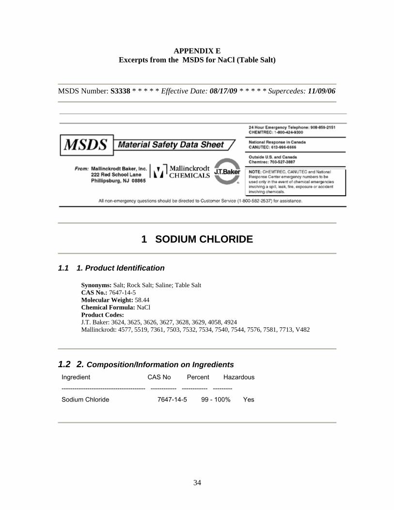
APPENDIX E Excerpts from the MSDS for NaCl (Table Salt)
MSDS Number: S3338 * * * * * Effective Date: 08/17/09 * * * * * Supercedes: 11/09/06
1 SODIUM CHLORIDE
1.1 1. Product Identification
Synonyms: Salt; Rock Salt; Saline; Table Salt CAS No.: 7647-14-5 Molecular Weight: 58.44 Chemical Formula: NaCl Product Codes: J.T. Baker: 3624, 3625, 3626, 3627, 3628, 3629, 4058, 4924 Mallinckrodt: 4577, 5519, 7361, 7503, 7532, 7534, 7540, 7544, 7576, 7581, 7713, V482
1.2 2. Composition/Information on Ingredients Ingredient CAS No Percent Hazardous --------------------------------------- ------------ ------------ --------- Sodium Chloride 7647-14-5 99 - 100% Yes

35
1.3 3. Hazards Identification
Emergency Overview -------------------------- WARNING! CAUSES EYE IRRITATION. SAF-T-DATA(tm) Ratings (Provided here for your convenience) ----------------------------------------------------------------------------------------------------------- Health Rating: 1 - Slight Flammability Rating: 0 - None Reactivity Rating: 0 - None Contact Rating: 1 - Slight Lab Protective Equip: GOGGLES; LAB COAT; PROPER GLOVES Storage Color Code: Green (General Storage) ----------------------------------------------------------------------------------------------------------- Potential Health Effects ---------------------------------- Inhalation: May cause mild irritation to the respiratory tract. Ingestion: Very large doses can cause vomiting, diarrhea, and prostration. Dehydration and congestion occur in most internal organs. Hypertonic salt solutions can produce violent inflammatory reactions in the gastrointestinal tract. Skin Contact: May irritate damaged skin; absorption can occur with effects similar to those via ingestion. Eye Contact: Causes irritation, redness, and pain. (For salt concentrations greater than the normal saline present.) Chronic Exposure: No information found. Aggravation of Pre-existing Conditions: No information found.
1.4 4. First Aid Measures
Inhalation: Remove to fresh air. Get medical attention for any breathing difficulty. Ingestion: If large amounts were swallowed, give water to drink and get medical advice. Skin Contact: Wash exposed area with soap and water. Get medical advice if irritation develops. Eye Contact: Immediately flush eyes with plenty of water for at least 15 minutes, lifting upper and lower eyelids occasionally. Get medical attention if irritation persists.

36
1.5 5. Fire Fighting Measures
Fire: Not considered to be a fire hazard. Explosion: Not considered to be an explosion hazard. Fire Extinguishing Media: Use any means suitable for extinguishing surrounding fire. Special Information: In the event of a fire, wear full protective clothing and NIOSH-approved self-contained breathing apparatus with full facepiece operated in the pressure demand or other positive pressure mode.
1.6 6. Accidental Release Measures
Ventilate area of leak or spill. Wear appropriate personal protective equipment as specified in Section 8. Spills: Sweep up and containerize for reclamation or disposal. Vacuuming or wet sweeping may be used to avoid dust dispersal. Small amounts of residue may be flushed to sewer with plenty of water.
1.7 7. Handling and Storage
Keep in a tightly closed container, stored in a cool, dry, ventilated area. Protect against physical damage. Containers of this material may be hazardous when empty since they retain product residues (dust, solids); observe all warnings and precautions listed for the product.
1.8 8. Exposure Controls/Personal Protection
Airborne Exposure Limits: None established. Ventilation System: In general, dilution ventilation is a satisfactory health hazard control for this substance. However, if conditions of use create discomfort to the worker, a local exhaust system should be considered. Personal Respirators (NIOSH Approved): For conditions of use where exposure to dust or mist is apparent and engineering controls are not feasible, a particulate respirator (NIOSH type N95 or better filters) may be worn. If oil particles (e.g. lubricants, cutting fluids, glycerine, etc.) are present, use a NIOSH type R or P filter. For emergencies or instances where the exposure levels are not known, use a full-face positive-pressure, air-supplied respirator. WARNING: Air-purifying respirators do not protect workers in oxygen-deficient atmospheres. Skin Protection: Wear protective gloves and clean body-covering clothing. Eye Protection:

37
Use chemical safety goggles. Maintain eye wash fountain and quick-drench facilities in work area.
1.9 9. Physical and Chemical Properties
Appearance: White crystals. Odor: Odorless. Solubility: 36g/100cc water @ 20C (68F) Specific Gravity: 2.16 pH: 6.7 - 7.3 (aqueous solution) % Volatiles by volume @ 21C (70F): 0 Boiling Point: 1413C (2575F) Melting Point: 801C (1474F) Vapor Density (Air=1): No information found. Vapor Pressure (mm Hg): 1.0 @ 865C (1589F) Evaporation Rate (BuAc=1): No information found.
1.10 10. Stability and Reactivity
Stability: Stable under ordinary conditions of use and storage. Hygroscopic. Hazardous Decomposition Products: When heated to above 801C (1474F) it emits toxic fumes of chloride and sodium oxide. Hazardous Polymerization: Will not occur. Incompatibilities: Lithium, bromine trifluoride. Conditions to Avoid: Incompatibles.
1.11 11. Toxicological Information
Oral rat LD50: 3000 mg/kg.

38
Inhalation rat LC50: > 42 gm/m3 /1H. Skin rabbit LD50: > 10 gm/kg. Investigated as a mutagen, reproductive effector.
--------\Cancer Lists\------------------------------------------------------ ---NTP Carcinogen--- Ingredient Known Anticipated IARC Category ------------------------------------ ----- ----------- ------------- Sodium Chloride (7647-14-5) No No None
1.12 12. Ecological Information
Environmental Fate: No information found. Environmental Toxicity: No information found.
1.13 13. Disposal Considerations
Whatever cannot be saved for recovery or recycling should be managed in an appropriate and approved waste disposal facility. Processing, use or contamination of this product may change the waste management options. State and local disposal regulations may differ from federal disposal regulations. Dispose of container and unused contents in accordance with federal, state and local requirements.
1.14 14. Transport Information
Not regulated.
1.15 15. Regulatory Information --------\Chemical Inventory Status - Part 1\--------------------------------- Ingredient TSCA EC Japan Australia ----------------------------------------------- ---- --- ----- --------- Sodium Chloride (7647-14-5) Yes Yes Yes Yes --------\Chemical Inventory Status - Part 2\--------------------------------- --Canada-- Ingredient Korea DSL NDSL Phil.

39
----------------------------------------------- ----- --- ---- ----- Sodium Chloride (7647-14-5) Yes Yes No Yes --------\Federal, State & International Regulations - Part 1\---------------- -SARA 302- ------SARA 313------ Ingredient RQ TPQ List Chemical Catg. ----------------------------------------- --- ----- ---- -------------- Sodium Chloride (7647-14-5) No No No No --------\Federal, State & International Regulations - Part 2\---------------- -RCRA- -TSCA- Ingredient CERCLA 261.33 8(d) ----------------------------------------- ------ ------ ------ Sodium Chloride (7647-14-5) No No No Chemical Weapons Convention: No TSCA 12(b): No CDTA: No SARA 311/312: Acute: Yes Chronic: No Fire: No Pressure: No Reactivity: No (Pure / Solid)
Australian Hazchem Code: None allocated. Poison Schedule: None allocated. WHMIS: This MSDS has been prepared according to the hazard criteria of the Controlled Products Regulations (CPR) and the MSDS contains all of the information required by the CPR.
1.16 16. Other Information
NFPA Ratings: Health: 1 Flammability: 0 Reactivity: 0 Label Hazard Warning: WARNING! CAUSES EYE IRRITATION. Label Precautions: Avoid contact with eyes. Wash thoroughly after handling. Label First Aid: In case of eye contact, immediately flush eyes with plenty of water for at least 15 minutes. Get medical attention if irritation develops or persists. Product Use: Laboratory Reagent. Revision Information: No Changes. Disclaimer: ************************************************************************************************

40
Mallinckrodt Baker, Inc. provides the information contained herein in good faith but makes no representation as to its comprehensiveness or accuracy. This document is intended only as a guide to the appropriate precautionary handling of the material by a properly trained person using this product. Individuals receiving the information must exercise their independent judgment in determining its appropriateness for a particular purpose. MALLINCKRODT BAKER, INC. MAKES NO REPRESENTATIONS OR WARRANTIES, EITHER EXPRESS OR IMPLIED, INCLUDING WITHOUT LIMITATION ANY WARRANTIES OF MERCHANTABILITY, FITNESS FOR A PARTICULAR PURPOSE WITH RESPECT TO THE INFORMATION SET FORTH HEREIN OR THE PRODUCT TO WHICH THE INFORMATION REFERS. ACCORDINGLY, MALLINCKRODT BAKER, INC. WILL NOT BE RESPONSIBLE FOR DAMAGES RESULTING FROM USE OF OR RELIANCE UPON THIS INFORMATION. ************************************************************************************************ Prepared by: Environmental Health & Safety Phone Number: (314) 654-1600 (314) 654-1600 (U.S.A.)

41
APPENDIX E Project Timeline

42
APPENDIX F Project Budget

43
APPENDIX G
Requirements Cross Reference
No. Requirement in SOW Proposal Section
1 The Vehicle shall carry a science or engineering payload of the team's discretion 4.5
2 The vehicle shall be developed so that it delivers the science or engineering payload closest to, but not exceeding an altitude of 5,280 feet above ground level
4.1, 4.4
3 The recovery system shall have the following characteristics: 3a Redundant altimeters 4.3, 4.3.1, 4.3.2
3b Each altimeter shall be armed by a dedicated arming switch and have a dedicated battery 4.3
3c Each arming switch shall be accessible from the exterior of the rocket airframe 4.3
3d Each arming switch shall be capable of being locked in the on position for launch 4.3
3e The recovery system shall be designed to be armed on the pad 4.3
3f The recovery electronics shall be completely independent of the payload electronics 4.5
4 The launch vehicle and science or engineering payload shall remain subsonic from launch until landing Table in 4.4
5 The launch vehicle and science or engineering payload shall be designed to be recoverable and reusable (launch again on the same day with no repairs or modifications)
4.1
6
Separation at apogee of payload components will be allowed, but not advised. Separating at apogee increases the risk of drifting outside of the recovery area. Exception: separating at apogee to deploy a drogue parachute
4.3
7 Dual deployment recovery shall be used 4.3
8 Removable shear pins shall be used for both the main parachute compartment and the drogue parachute compartment 4.1
9 The vehicle, or any un-tethered sections, shall have a landing velocity under the main parachute(s) between 17 and 22 ft/s inclusive
Table 2 in 4.1
10 The vehicle, or any un-tethered sections, shall have a descent rate under the drogue parachute(s) between 50 and 100 ft/s inclusive Table 2 in 4.1
11 Each rocket shall be capable of being prepared for flight at the launch site within 4 hours, from the time the waiver opens at the field until RSO inspections have been successfully completed
4.3
12 All vehicle and payload components shall be designed to land within 2500 ft of the pad with a 10 mile/hour wind Table 2 in 4.1
13 After being fully armed for launch, the rocket shall be capable of remaining on the pad for 1 hour before launching without losing the functionality of any vehicle or payload compartment
4.3, 4.6.1.1

44
14
Rockets shall be launched from a standard firing system (provided by the Range) that does not need additional circuitry or special ground support equipment to initiate the flight or complicate a normal 10 second countdown
4.2
15 Data from the science or engineering payload shall be collected, analyzed, and reported by the team following the scientific method 4.5
16
An electronic tracking device shall transmit the rocket's position via radio/GPS frequency to the ground. Every un-tethered section of the vehicle must have is own transmitting tracking device. Audible beepers may be used for recovery in conjunction with an electronics transmitting device, but shall not be used as a replacement for a transmitting tracking device
4.6
17
The rocket shall use commercially available solid motor propulsion system using ammonium perchlorate composite propellant (APCP) which is approved and certified by the National Association of Rocketry (NAR), Tripoli Rocketry Association (TRA) and/or the Canadian Association of Rocketry (CAR)
4.4
17a
New Teams; Maximum total impulse provided by the entire vehicle shall not exceed 2.560 Newton-seconds (K-class). This total impulse constraint is applicable to any combination of single motor, clustered motors, and staged motors.
4.4
18
All teams shall successfully launch their full scale rocket prior to FRR in its competition flight configuration. The vehicle and recovery system must have functioned as designed. The payload does not have to be flown during the full-scale test flight. If the payload is not flown on the full-scale test flight, mass simulators should be used to simulate the missing payload mass. If the payload changes the external surfaces (cameras, movable fins, etc.), those devices must be flown during the full scale test flight. The purpose is to verify the vehicle's stability, structural integrity, recovery systems, and the team's performance. The flight certification form will be filled out by an L2 NAR/TRA observer. Subscale motors may be used on the full scale test flight
4.1, Appendix E
19 The following items are prohibited from use in the rocket:
19a Flashbulbs. The recovery system must use commercially available low-current electric matches 4.3
19b Forward canards 4.1 19c Forward firing motors 4.1 19d Rear ejection parachute designs 4.1
19e Motors which expel titanium sponges (Sparky, Skidmark, MetalStorm etc.) 4.1, 4.4
20 Each team shall use a launch and safety checklist. The final checklist shall be included in the FRR report and used during the flight hardware and safety inspection and launch day
4.2
21
Students on the team shall do 100% of the work on the project, including design, construction, written reports, presentations, and flight preparation with the exception of assembling the motors and handling all black powder charges
1.6