Embed Size (px)
Citation preview

Issued for Tender WSP Project No. 191-03785-00
November 6, 2020
PROJECT MANUAL AND SPECIFICATIONS FOR REMEDIAL WORK
Department of Fisheries and Oceans RPSS Major Facilities
Stores Building Recladding
25 Huron Street, Victoria, BC
WSP CANADA INC. #301 – 3600 Uptown Boulevard, Victoria, BC

DFO RPSS Stores Warehouse Recladding TABLE OF CONTENTS
WSP Project No. 191-03785-00
2020-11-06 Page 1 of 1
wsp.com
SPECIFICATIONS
DIVISION 1 GENERAL REQUIREMENTS
Section 01 00 00 General Requirements 1-14
Section 01 11 00 Scope of Work 1-3
Section 01 11 01 Schedule A – Schedule of Exterior Wall Penetrations 1-4
Section 01 33 00 Submittals Procedure 1-2
DIVISION 2 EXISTING CONDITIONS
Section 02 41 13 Selective Demolition 1-5
DIVISION 7 THERMAL AND MOISTURE PROTECTION
Section 06 10 53 Rough Carpentry 1-2
Section 07 41 20 Profiled Metal Cladding 1-4
Section 07 45 00 Fibre Cement Panel and Trim 1-2
Section 07 62 00 Sheet Metal Flashing and Trim 1-4
Section 07 92 00 Sealant 1-4
DIVISION 8 THERMAL AND MOISTURE PROTECTION
Section 08 11 00 Hinged Metal Doors
Section 08 36 19 Multi-leaf Vertical Lift Metal Doors
DIVISION 9 FINISHES
Section 09 91 00 Painting 1-5
DIVISION 26 ELECTRICAL
Section 26 50 00 Lighting General 1-7
END OF TABLE OF CONTENTS
DFO RPSS Stores Warehouse Recladding SECTION 01 00 00
WSP Project No. 191-03785-00 GENERAL REQUIREMENTS
2020-11-06 Page 1 of 13
wsp.com
1.1. DRAWINGS AND SPECIFICATIONS
.1 Ensure that the Work includes all labour, equipment and Products required, necessary or normally recognized within
respective trade practices, as necessary for the proper and complete execution of the Work.
.2 Perform all Work in accordance with the drawings, specifications, Consultant's directions, manufacturer's printed
instructions, approved samples, mockups and the requirements of regulatory authorities having jurisdiction as
applicable.
.3 The language of the specifications is in many cases written in the imperative mood for brevity. Clauses containing
instructions or directions are directed to the Contractor and in the case of conflicts such sentences are presumed to
include the words "the Contractor shall."
.4 The sections of Division 1 of the specifications form part of and are to be read in conjunction with the technical sections
of the specifications.
.5 Drawings are diagrammatic and are intended to convey the intent of the Work and, as such, show the extent of existing
construction and remedial work required as far as is practical. Where the drawings do not illustrate specific details for
portions of the Work, construct such portions to match the new or existing work as applicable.
.6 The details shown are included for the purpose of indicating the preferred profiles and dimensions necessary to achieve
the design intent. Minor dimension adjustments to that shown may be made in the proposed design in the interest of
fabrication or erection methods or techniques, verified site conditions, the weatherability factor, or the ability of the
design to satisfy the design and performance requirements specified, provided that the design intent is maintained.
.7 The existing construction as shown on the drawings has been determined from available records and may not represent
the actual site conditions in all locations. The Contractor may encounter site conditions which may vary slightly from
those shown on the drawings and unless such conditions are found to be significantly different by the Consultant, the
Contractor will not be entitled to any change in Contract Price or Contract Time.
.8 Where job conditions require reasonable adjustments in the indicated locations and extent, make the necessary
modifications at no additional cost to the Owner.
.9 Work described in this specification has been organized and arranged into sections based on the Construction
Specifications Canada MasterFormat system.
.10 The specifications and drawings are arranged in a manner to indicate the content of the Work. These sections do not
however obligate the Consultant to establish limits or limit the responsibility of any Subcontractor or supplier. The
onus for defining the extent of the Subcontractor's work remains with the Contractor to interpret all documents as a
whole, and who will ensure that when awarding subcontracts, the area or scope of responsibility of any particular
Subcontractor or supplier is set out in full detail.
.11 Division 1 of the specification specifies Work that is the direct responsibility of the General Contractor, administrative
procedures and general requirements applying to Subcontractors. Division 1 will not be interpreted as defining limits
of responsibility between the Contractor and its Subcontractors.
.12 Ensure that Subcontractors understand that the General Conditions of the Contract and Division 1 apply to sections of
the specification governing their Work.
.13 Wherever the word "building" occurs in the Contract Documents, it is to be taken to mean all the buildings or parts
thereof included in the Contract.

DFO RPSS Stores Warehouse Recladding SECTION 01 00 00
WSP Project No. 191-03785-00 GENERAL REQUIREMENTS
2020-11-06 Page 2 of 13
wsp.com
.14 Wherever in the Contract Documents the words "approval", "approved", "direction", "directed", "selection", "selected",
"request", "requested", "report", "reviewed" and similar words are used, such approvals, directions, selections, requests
and reports will be given by the Consultant unless specifically stated otherwise.
.15 Wherever in the Contract Documents the word "provide" is used in any form, it means that the Work concerned includes
both supply and installation of the products required for the completion of that part of the Work.
.16 Wherever in the Contract Documents the word "supply" is used in any form, it means that the Work specified to be
supplied includes delivery to site and unloading at location directed.
.17 Wherever in the Contract Documents the word "installed" issued in any form, it means Work specified for installation
includes receiving, uncrating, unpacking; moving from stored location to place of installation; and installing to meet
specified requirements.
.18 Wherever in the Contract Documents it is specified that Work is to proceed or to meet approval, direction, selection or
request of jurisdictional authorities or others, such approval, direction, selection or request must be in writing.
.19 Wherever in the Contract Documents or as directed by the Consultant it is specified that Work is to be repaired, made
good or replaced, perform the work without any additional cost to the Owner.
.20 Wherever in the specifications the term "Related Sections" is used, it is to be taken to mean Work that is directly related
to the section but not specified therein. The purpose of this clause is to redirect the reader to other sections of the
specification for Work related to this section. This clause will not be construed as a definition of trade responsibility,
nor is it exhaustive in its description of related Sections and is included for convenience only.
1.2. CODES, STANDARDS, REGULATIONS
.1 Execute the Work in accordance with applicable bylaws, regulations, and building codes; conform to latest published
revisions, addenda, supplementary or appropriate current standards presently recognized and enforced by authorities
having jurisdiction. Should conflicts arise between one document or authority and another, obtain clarification from
the Consultant before proceeding with Work. Generally, the most stringent regulation will govern.
.2 Except where a reference standard is specifically dated in the specifications, references to standards will be taken to
mean the latest edition in effect at the date of award of the Contract. In the case of standards (dated or not) which appear
in the specifications and which are referenced in the municipal building code, the specific edition of the standard
referenced in the code governs. Where a standard is revised, supplemented or amended after award of the Contract,
carry out the Work in accordance with latest edition of such standards. If the revision to the standard is such that a
revision to the Contract Price is necessary, submit claims to the Owner in accordance with GC 6.2.
.3 Conform to all standards as specified herein and provide the Consultant with material conformity if requested. Where
published trade association standards manuals are called for in sections of the specifications, conform to those standards
unless approval to vary from the standard is given by the Consultant.
.4 Conform to Workers' Compensation Board (WCB) and other regulations governing safety at the Work.
.5 Provide hoardings and barricades in accordance with requirements of local authorities having jurisdiction and for
protection of the Owner, its tenants and the public in the vicinity of the Work.
.6 Provide signs and barricades to warn the public of construction activities going on overhead.
DFO RPSS Stores Warehouse Recladding SECTION 01 00 00
WSP Project No. 191-03785-00 GENERAL REQUIREMENTS
2020-11-06 Page 3 of 13
wsp.com
1.3. MOULD AND WORKER SAFETY
.1 The workers might be exposed to various moulds that may be contained within the building’s walls.
.2 In the event of discovery of any substance that might be suspected of being a mould or fungi growth, the Contractor
should notify the Owner.
.3 It will be the responsibility of the Owner to retain an independent specialty consultant whose responsibility will be to
advise the Owner of any course of action related to any suspected presence of mould or fungi growth.
.4 A safe workplace is mandated by law in Canada under various legislative frameworks. These include the provincial
occupational health and safety acts, the Workplace Hazardous Materials Information System (WHMIS), the Canada
Labour Code, and Transport Canada’s Transportation of Dangerous Goods (TDG) Act and Regulations.
.5 Both the Contractor and Owner agree that there are risks for this Contract being delayed or temporarily suspended as
a result of the Covid-19 pandemic. The Contractor agrees that they will apply the precautions required to limit the
spread of the virus as required or recommended by Health Authorities or other authorized Government. If work is
required to be temporarily suspended, the Contractor also agrees to either protect and maintain the site in a safe
condition, or temporarily demobilize and re-mobilize equipment at a later date. The Contractor agrees that there will
be no additional cost for these measures. The Owner agrees that the Contract schedule will be extended to the extent
that these measures impose delay and/or suspension of work.
1.4. CONSTRUCTION SCHEDULE
.1 Submit a Construction Schedule to the Consultant for review not later than 10 Working Days following the award of
the Contract.
.2 The Construction Schedule is to provide sufficient detail of the critical events and their inter-relationship to demonstrate
that the Work will be performed in conformity with the Contract Time.
.3 Prepare the schedule in the following format.
.1 Prepare schedule in the form of a horizontal bar chart.
.2 Prepare a bar for each trade or operation.
.3 Provide a horizontal time scale identifying the first work day of each week.
.4 Format For Listings: Chronological order of start of each item of work.
.5 Three week schedule window to be updated bi-weekly.
.6 Ensure the schedule allows for the opening and securely closing of the building envelope at the end of each
workday.
.4 Identify the Contractor's proposed phasing for execution of the Work and take into account the Owner's occupancy and
the presence of the public during the construction period.
.5 Submit a written statement to the Consultant on a twice monthly basis, that the Work is being performed substantially
in accordance with the agreed construction schedule, if this is the case, or state if those operations are not being so
performed. In the latter case, state the reason for delay of any work together with its proposed method of restoring the
progress to that required by the agreed progress schedule, including such additional graphic presentation, to
demonstrate that the completion date for the Work will be maintained or will be extended pursuant to GC 6.5.

DFO RPSS Stores Warehouse Recladding SECTION 01 00 00
WSP Project No. 191-03785-00 GENERAL REQUIREMENTS
2020-11-06 Page 4 of 13
wsp.com
1.5. SUBMITTALS
.1 Provide submittals listed in the specification sections for review. Submit with reasonable promptness and in orderly
sequence so as to not cause delay in the Work. Do not proceed with work affected by the submittal until review is
complete.
.2 Review submittals prior to submission to the Consultant. This review represents that necessary requirements have
been determined and verified, or will be, and that each submittal has been checked and coordinated with requirements
of the Work and the Contract Documents. Submittals not stamped, signed, dated and identified as applying specifically
to the Project will be returned without being examined and are required to be resubmitted when completed.
.3 The Contractor's responsibility for deviations in submission from the requirements of Contract Documents is not
relieved by the Consultant's review of submittals, unless a deviation on the submittal is noted as such in writing and
has been approved by the Consultant.
.4 Submit a digital copy of shop drawings for each requirement requested in specification sections. The Consultant
requires a minimum of ten (10) working days to review shop drawings from the date they are received. Submit sealed
original shop drawings to the Consultant where required.
.5 Submit a digital copy of all product data sheets and MSDS sheets or brochures identifying each product specifically
for the requirements requested in specification sections where shop drawings will not be prepared due to standardized
manufacture of product. Product data sheets will only be accepted if: information not applicable to the Project is deleted,
additional information is provided as required to supplement standard information, dimensions, clearances,
performance characteristics and limitations are shown.
.6 If, upon review by the Consultant, only minor corrections are to be made, shop drawings will be returned and fabrication
and installation of work may proceed. If shop drawings are rejected, a noted copy will be returned and resubmission
of corrected shop drawings, through the same procedure indicated above, must be performed before fabrication and
installation of work may proceed.
.7 Submit samples in sizes and in duplicate as requested in respective sections. Submit full range of colours where colour
samples are called for. The approved sample will serve as the control sample against which all other work will be
judged.
1.6. MAINTENANCE MANUALS
.1 Submit a digital copy of each required warranty, guarantee, and data sheets covering the care, cleaning and
recommended maintenance procedures for materials installed as part of the Work.
1.7. RECORD DRAWINGS
.1 The Consultant will provide, one (1) set of white prints of all Contract drawings necessary for the sole purpose of
recording all "as-built conditions" of deviations from the Contract Documents. Clearly identify them as "record
drawings" and have them available at all times and at each regular project progress site meeting for review or scrutiny
and as may be required by the Consultant.
.2 As work progresses, record clearly and indelibly in red pencil all "as-built" deviation from the Contract Documents as
a result caused by site conditions or various directives by addenda, correspondence, site clarifications, site instructions,
change orders, shop drawings and authorities having jurisdiction, back-referencing said changes. Record locations of
concealed components of mechanical and electrical services.
DFO RPSS Stores Warehouse Recladding SECTION 01 00 00
WSP Project No. 191-03785-00 GENERAL REQUIREMENTS
2020-11-06 Page 5 of 13
wsp.com
1.8. FIELD OFFICES
.1 Optional: Provide and maintain a locked trailer or partitioned area on site for use as a field office. Location to be agreed
upon by the Client and Contractor prior to proceeding. Mandatory: Cell phone and email access on site.
.2 Keep a copy of the Contract drawings, specifications, reviewed shop drawings, Product data and installation
instructions, samples, change notices, change orders, test reports, permits, construction schedule and other project
related documentation on site.
1.9. MEETINGS AND PROGRESS REPORTS
.1 Project meetings with the Contractor, Owner, and Consultant will be held at the site on a bi-weekly basis.
.2 Hold regular meetings with Subcontractors as required for the performance of the work.
.3 Supply for distribution, a minimum of every 2 weeks, a short written description of the Project status and specific
information about the Work that will affect the operations of the Owner. Increase the frequency of the submission as
necessary to keep the Owner informed. Communicate with the Owner’s representative and Consultant with respect to
all issues impacting the building occupants use of the site and the building.
1.10. TEMPORARY POWER AND WATER
.1 The Owner will provide a source of temporary power and water without charge to the Contractor. The power provided
by the Owner is limited, use for the operation of small tools and equipment only. Provide and pay for an independent
source of temporary power required for tools and equipment demanding excessive power loads. Pay cost for permits,
installation, maintenance and removal of temporary power.
.2 The Contractor is responsible for ensuring that the Owner's electrical circuits are functioning properly at the end of
each work shift and that extension cords, tools, hoses and equipment have been disconnected. Make good damage
caused to the Owner's services.
1.11. TEMPORARY HEAT AND HOARDING
.1 Provide and pay for temporary heat and hoarding as required to provide and maintain adequate installation and curing
temperatures as required by the specifications or manufacturer's printed installation instructions and maintain the
Construction Schedule.
.2 Take all measures to reduce the impact of the hoarding on the Owner and its tenants and to minimize the duration of
the erection of the hoarding in any one location any longer than necessary to complete the Work.
1.12. SANITARY FACILITIES
.1 Provide and maintain during the Work regularly serviced chemical toilets for use of all personnel employed on the
Work.
.2 The Owner's facilities are not available for use by the Contractor.
1.13. FIRE PROTECTION
.1 Maintain access for the fire department to the Work and sprinkler connections.
.2 Keep fire extinguishers on hand at all times.

DFO RPSS Stores Warehouse Recladding SECTION 01 00 00
WSP Project No. 191-03785-00 GENERAL REQUIREMENTS
2020-11-06 Page 6 of 13
wsp.com
1.14. FIRST AID
.1 Provide a worker trained in first aid procedures on the site at all times during the performance of the Work. Provide a
first aid station.
1.15. SIGNS
.1 Do not place signs on the site without the express consent of the Owner.
1.16. PARKING
.1 Parking is as specified on sheet BE2.00.
1.17. CONSTRUCTION NOISE
.1 Unless otherwise approved by the Consultant, perform work involving excessive noise, vibration, including but not
necessarily limited to jack hammers, concrete saws, concrete drills, steel saws, explosive activated tools or activities
disruptive to the normal operation of the Owner or dangerous to the occupants during time periods approved by the
Owner and Consultant.
.2 Comply with the requirements of authorities having jurisdiction, the Owner and Consultant regarding noise abatement
and take all necessary steps to ensure that the generation and transmission of noise and vibration due to this Work is
kept to minimum.
.3 Maintain construction methods to ensure a low level of construction noise. Keep all equipment as quiet as practicable
and the noise emission as low as possible by using sound enclosures, sound baffles, muffler-equipped equipment and
vibration platforms.
.4 Air driven grinders will not be permitted for use in the Work.
1.18. TEMPORARY EXIT FACILITIES
.1 The following guidelines are presented as a minimum standard for the provision of temporary exit facilities during the
course of construction. The Contractor shall ensure and obtain written confirmation from the authorities having
jurisdiction, that the required means of egress are maintained at all times. A construction security plan must be filed
with, coordinated with, and approved by the Owner.
1.19. LIFE SAFETY WIRING
.1 The building will be occupied 24 hours 7 days per week during the remedial work. It is essential that an adequate level
of life safety be maintained during construction. The following guidelines are intended as a minimum standard for the
maintenance and operation of life safety systems during construction:
.1 A certified electrician must perform temporary disconnection and re-connection of any fire and life safety
wiring or security systems.
.2 If any emergency lighting is disconnected, temporary emergency lights should be installed in close proximity
before the close of the business day.
.3 If any exit lights are disconnected, temporary exit lights should be installed in close proximity before the close
of the business day.
.4 If any exit facilities are temporarily shut down, the exit directional signs associated with this facility should

DFO RPSS Stores Warehouse Recladding SECTION 01 00 00
WSP Project No. 191-03785-00 GENERAL REQUIREMENTS
2020-11-06 Page 7 of 13
wsp.com
be temporarily covered over.
.5 If any fire and life safety systems must be shut down overnight, or for an extended period, a full time security
guard is required during non-working hours to provide a “fire watch” program.
1.20. EXISTING SERVICES
.1 Become familiar with all available information and documents regarding existing building services and ensure that
they are maintained continuously throughout the entire period of construction and alterations. Keep any temporary
interruptions to electrical power, water, fire protection system and other services to an absolute minimum and the work
performed to have the least impact on operations. Required interruptions to any existing services, including fire
protection system, must be by prior arrangement with and approval of the Owner and Consultant at least 72 hours
before interruption. Report interruptions to the fire protection system to the Fire Department.
1.21. STORAGE AND HANDLING
.1 Conform to the material manufacturer's directions as a minimum for the delivery, storage and handling of Products.
Store in original containers with all labels and seals intact. Prevent materials from freezing, excessive heat, moisture,
soiling and sunlight as directed by the manufacturer. Store all flammable, corrosive or toxic substances in suitable
containers clearly labelled. Store in separate storage sheds away from the main building structure and in strict
accordance with the manufacturer's directions.
.2 Storage area for materials on site is limited and is generally restricted to within site areas. Deliver materials to the site
consistent with progress schedule and so as to not unreasonably encumber the premises with materials. Be responsible
for the security of products stored on site.
.3 Do not store materials adjacent building exits and building access points.
.4 Store materials to avoid damage to landscaped areas.
1.22. OWNER OCCUPANCY
.1 Construct Work in stages to accommodate the Owner's use of premises during construction. Construct Work in stages
to provide for continuous usage.
.2 Maintain free access by the Owner to areas not under construction at all times. Provide temporary slip-resistant ramps
or raised platforms to maintain equipment access to pre-existing conditions.
.3 Maintain existing entrances and fire exits free from obstruction throughout alteration Work. Provide alternative and
additional exits where required by authorities having jurisdiction and the requirements for temporary exits stated in
clause 1.19.
.4 Conduct all construction activities in a manner that respects the continuing activities of the Owner and presence of the
public during the Work.
.5 The Owner has complete jurisdiction over the entry of workers to the existing premises and control of construction
deliveries to the site.
.6 The Owner reserves the right to suspend construction operations where such operations are disruptive to the Owner.
1.23. WORK AREAS
.1 The limit of the Work of the Contract is designated on the drawings. The Consultant, however, will designate the exact
boundaries of the working areas in consultation with the Owner and the Contractor in which the Contractor will operate.

DFO RPSS Stores Warehouse Recladding SECTION 01 00 00
WSP Project No. 191-03785-00 GENERAL REQUIREMENTS
2020-11-06 Page 8 of 13
wsp.com
1.24. HOURS OF WORK
.1 Carry out the Work only during weekdays between 07:30 hours and 17:00 hours. The Owner may permit a limited
amount of work to be carried out during evenings and on weekends and such work will be authorized by the Owner in
advance.
1.25. SECURITY AND ACCESS
.1 The Owner will occupy premises during entire construction period and will require that the building enclosure be
opened and resealed within each working day. The facility is guarded 24-7. Do not deconstruct an area unless it can
be re-enclosed securely that same day.
.2 Provide scaffolding, ladders etc, as required for access to Work areas. Access through the building is not permitted,
unless prior approval is obtained from the Owner.
.3 Abide by the Owner's security requirements during the Work. Obtain Owner's permission prior to commencing any
work and ensure workers observe all of the existing security regulations wherever such regulations apply.
.4 Make provision to maintain security in a manner acceptable to the Owner.
.5 The Owner does not provide any security service for the Contractor.
.6 Ensure that all openings to buildings are properly closed in with secure barricades. Work to exterior walls must be
scheduled so that the walls can be made secure against forced entry at the completion of each work day.
.7 Provide the Owner with names and phone numbers to contact at night, in case of emergency.
.8 Sign out all keys and return to the Owner upon completion of the Work.
1.26. SECURITY WIRING AND CAMERAS
.1 The facility will remain active and accessed by staff during the remedial work. Where panels are being replaced and
security wiring and cameras and mounts are requiring disconnection or reconnection, the Contractor must notify the
Owner with 5 working day’s notice. The Contractor will set up access to the camera or security system so that the
Owner’s trade can access the device safely. The Owner will coordinate and pay their security firm to execute the work
as needed.
.2 Once the Project is complete, the Owner will retain their security firm to re-verify their security systems. The
Contractor will re-verify the fire alarm system with certification provided to the Consultant
1.27. SITE INSPECTION
.1 Before commencing the Work, visit the site and report to the Consultant any conflicts between existing site conditions
and the requirements for the Work.
.2 Report to the Consultant any defects or conditions in the existing construction which would affect the proper
performance of the Work. Commencement of the Work will imply acceptance of existing conditions and substrates.
1.28. PRE-CONSTRUCTION INSPECTION
.1 Undertake a pre-construction survey prior to undertaking any work. Record all observations in writing or by
photographic or video record and notify the Consultant in writing of any existing suite damage prior to commencing

DFO RPSS Stores Warehouse Recladding SECTION 01 00 00
WSP Project No. 191-03785-00 GENERAL REQUIREMENTS
2020-11-06 Page 9 of 13
wsp.com
the work. Any claims for damage that were not identified in the pre-construction survey or that can not be proved
existed prior to commencement of the Work, or that are not a direct result of normal construction procedures during
the remediation, will be paid for by the Contractor.
1.29. EXISTING CONDITIONS
.1 If while carrying out the Work, conditions are exposed which are in contravention with applicable regulatory codes
and requirements of authorities having jurisdiction, unsafe or in any way less than the acceptable industry standard for
the particular item, immediately notify the Consultant before proceeding with further work. The Consultant will review
the condition and issue the appropriate instruction.
.2 Break into existing utilities, services and other areas of the Work as required to make proper connections to existing
work. Patch and make good existing work that may be damaged through the Work and reasonably match new to existing
in all respects. Use extreme care when breaking into existing work as some services may not be shown or identified.
1.30. LAYOUT
.1 Locate all general reference points. Layout own work and be responsible for all lines, elevations and measurements of
building, services, equipment, fixtures and other work as required. Exercise proper precautions to verify site
measurements and dimensions shown on the drawings, before laying out work. Be responsible for any error resulting
from failure to exercise such precaution.
1.31. MOCKUPS
.1 Prior to undertaking wide spread repairs, construct a representative area of wall including as applicable, a window,
outswing door, overhead door, corners, and soffit interface.
.2 The approved mockup will serve as the standard upon which all other work will be judged.
.3 Do not proceed with the work until mockup is approved by the Consultant.
1.32. PROTECTION
.1 Protect adjacent private property from construction debris, dust, operations and damages at all times during
performance of the Work. Contain all construction activities and operations within the perimeter of the site property
lines. Be responsible for damage incurred.
.2 Protect landscaped areas from damage. Take adequate measures to prevent damage to plant material and grassed areas.
Identify any landscaping element which will prevent the performance of the Work, the Owner will make arrangements
for removal and reinstatement.
.3 The provision of hoarding at building access points and exits to protect against overhead falling construction materials,
debris and equipment is mandatory.
.4 Provide and maintain suitable scaffolding with debris mesh on the outside and a tarp at the top to protect the structure
and all components from the elements and to ensure that the moisture content of the wood does not exceed specified
standards.
.5 Take special precautions to protect existing building areas, when exposed, by removal of existing walls, roofs or other
exterior surfaces. Take all necessary precautions and measures to ensure the interior of the existing building is
weathertight, insulated and fully secure at all times. Suspend work and make building watertight or provide weather
protection, when rain is eminent. Ensure the building is protected against the weather at the end of each work day.
.6 Make good damage of any nature to existing building or its contents, except where required by the Work, to the
satisfaction of the Consultant and at no additional cost to the Owner. Making good will mean restoration to at least

DFO RPSS Stores Warehouse Recladding SECTION 01 00 00
WSP Project No. 191-03785-00 GENERAL REQUIREMENTS
2020-11-06 Page 10 of 13
wsp.com
original condition in terms of strength, safety, workmanship and appearance.
.7 Protect remaining finishes, equipment and adjacent work from damage caused by cutting, moving, removal and
patching operations. Protect surfaces which will remain a part of the finished work.
.8 Remove debris promptly from the area of work. Load removed material directly into bins for removal from site.
.9 Suppress dust. Prevent the occurrence of unsanitary conditions, dirt or debris on the site.
1.33. PRODUCTS
.1 Use new Products unless otherwise specified in the Contract Documents. Products which are not specified are to be of
a quality best suited to the purpose required and their use is subject to the approval of the Consultant.
.2 Remove materials not so conforming to the Contract Documents or containing defects deemed irreparable by the
Consultant.
.3 Defective Products, whenever identified prior to completion of the Work, will be rejected, regardless of previous
reviews by the Consultant. Reviews by the Consultant do not relieve responsibility, but are a precaution against
oversight or error. Remove and replace defective Products at own expense and be responsible for delays and expenses
caused by rejection.
.4 Should any dispute arise as to the quality or fitness of Products, the decision rests strictly with the Consultant based
upon requirements of the Contract Documents.
.5 Unless otherwise indicated in the specifications, maintain uniformity of manufacture for any particular or like item
throughout the Work.
.6 Permanent labels, trademarks and nameplates on products are not acceptable in prominent locations, except where
required for operating instructions or when located in mechanical or electrical rooms.
.7 Provide fastenings and accessories in same material, texture, colour and finish as adjacent materials, unless indicated
otherwise. Prevent electrolytic action between dissimilar metals and materials. Space anchors within their load limit
or shear capacity and ensure they provide positive permanent anchorage. Plastic, wood or any other organic material
plugs are not acceptable. Keep exposed fastenings to a minimum, space evenly and install neatly. Fastenings which
cause spalling or cracking of material to which anchorage is made are not acceptable.
1.34. MATERIALS AVAILABILITY
.1 Upon award of the Contract, determine the availability and delivery time necessary for all products, equipment and
plant required for the Work to be completed by the agreed date of Substantial Performance of the Work. Order items
to ensure that delivery to the Work is such that the agreed progress schedule will be maintained.
.2 Within ten (10) Working Days confirm in writing that all specified materials are available for incorporation into the
Work. Identify items/materials with long delivery dates. Submit a schedule of planned ordering dates, and submit
confirmation of placement of each order.
1.35. MANUFACTURER'S INSTRUCTIONS
.1 When Work is specified to comply with the manufacturer's instructions, distribute copies to persons involved, and
maintain one (1) set in field office.
.2 Perform Work in accordance with details, instructions and specified requirements. Should a conflict exist between
specifications and instructions, consult the Consultant.

DFO RPSS Stores Warehouse Recladding SECTION 01 00 00
WSP Project No. 191-03785-00 GENERAL REQUIREMENTS
2020-11-06 Page 11 of 13
wsp.com
.3 Improper installation or erection of products, due to failure in complying with these requirements, may result in the
Consultant requiring the Work be removed and reinstalled according to manufacturer's instructions at no increase to
the Contract Price or Contract Time.
1.36. WORKMANSHIP
.1 Execute workmanship using workers experienced and skilled in the respective duties for which they are employed.
.2 Do not employ any unfit person or anyone unskilled in his required duties. The Owner reserves the right to require the
dismissal from the site of workers deemed incompetent, careless, insubordinate or otherwise objectionable.
.3 Decisions as to the quality or fitness of workmanship in case of dispute rest solely with the Consultant, whose decision
is final.
1.37. CUTTING, PATCHING, EXTENDING AND MATCHING
.1 Work performed and materials used to patch, extend or match existing construction, must be not less than the standard
of quality for the existing building, except where such existing materials are no longer available, are inappropriate for
the intended reconstruction or detailed otherwise on the drawings.
.2 These specifications will generally not describe existing products or standards of execution, the existing product is its
own specification.
.3 Perform patching, extending and matching work so as to return existing construction to original standards of quality
and visual appearance.
.4 Take care to avoid damage to other work. Cut rigid materials using power saws or core drills. Pneumatic or impact
tools are not permitted.
.5 Replace work damaged in the course of alterations, except at areas approved by the Consultant for repair.
.6 Patch and extend existing work using skilled mechanics who are capable of matching the existing quality of
workmanship.
.7 Do not incorporate salvaged or used material in new construction, except where small quantities of finish material
which are difficult to match or duplicate are approved for patching or extending purposes by the Consultant.
.8 Provide adequate support or substrate for patching of finishes.
.9 If the imperfect surface was painted or coated, repaint or recoat the patched portion in such a way that uniform,
matching colour and texture over the entire surface results.
.10 If the surrounding surface cannot be matched, repaint or recoat the entire surface.
.11 The quality of the products that exist in the building, as apparent during pre-bid site visits, will serve as the specification
requirement for strength, appearance and other characteristics.
.12 Where new work abuts or finishes flush with existing work, make the transition as smooth and workmanlike as possible.
Patched work must match existing adjacent work in texture and appearance so as to make the patch or transition
invisible to the eye at a distance of 10'-0".
.13 Where wood, metal or other finished surface is cut in such a way that a smooth transition with new work is not possible,
terminate the existing surface in a neat fashion along a straight line at a natural line of division and provide trim
appropriate to the finished surface.

DFO RPSS Stores Warehouse Recladding SECTION 01 00 00
WSP Project No. 191-03785-00 GENERAL REQUIREMENTS
2020-11-06 Page 12 of 13
wsp.com
.14 Restore existing work that is damaged during construction to a condition equal to its condition at the time of the start
of work.
1.38. CLEANUP
.1 Keep site clean and free of unsightly collection of waste materials and debris.
.2 The Contractor is responsible for the costs to provide garbage containers and removal of containers and debris from
the site, including any associated disposal costs.
.3 Provide for collection and temporary storage of waste materials and debris, in metal containers with lids. Dispose of
waste materials and debris to approved disposal site and to the requirements of local authorities having jurisdiction. Do
not dispose of waste or volatile materials such as mineral spirits, solvents, oil, or paint thinner into sewer or drainage
systems.
.4 Locate garbage containers in locations acceptable to the Owner.
.5 Provide waste disposal deposit slips to the Owner.
.6 Keep loading areas clean of debris. Clean at the end of each work day.
.7 Clean the interior and exterior of windows immediately following removal and replacement or after undertaking any
work that affects those surfaces.
.8 After completion of the Work, clean the exterior of all windows.
1.39. CLEANING
.1 Upon completion and prior to Substantial Performance of the Work, perform final cleaning and adjustments.
.2 Remove grease, paint spots, dirt, dust, stains, labels, fingerprints and other foreign matter from surfaces.
.3 Repair, patch and touch-up marred surfaces to match adjacent finishes. Replace cracked and broken glass. Ensure that
cleaning agents and methods do not remove finishes and permanent protective coatings on surfaces being cleaned.
.4 Leave all surfaces perfectly clean and in unsoiled condition.
.5 Clean mechanical, plumbing and electrical fixtures and equipment.
.6 Clean up at the end of each day and keep dust and contamination of the Work to a minimum.
.7 All landscaped areas are to be cleaned, grass re-seeded where required and the site returned to its original condition
before the start of construction.
1.40. CONTRACT CLOSEOUT
.1 Submit the following prior to the issuance of the certificate of Substantial Performance of the Work:
.1 Release from Worker's Compensation Board indicating all assessments due have been paid.
.2 Inspection and approval certificates of all authorities having jurisdiction.
.3 Reconciliation of change orders.
.4 List of any construction claims not yet submitted.

DFO RPSS Stores Warehouse Recladding SECTION 01 00 00
WSP Project No. 191-03785-00 GENERAL REQUIREMENTS
2020-11-06 Page 13 of 13
wsp.com
.5 Execute transition of Performance and Labour and Materials Payment bonds to warranty period requirements.
.6 As-built drawings showing changes cross-referenced with change orders, change directives, and
supplementary instructions, and/or any other relevant documentation and dates of communication justifying
the change.
.2 Submit the following not later than 10 Working Days after issuance of the certificate of Substantial Performance of the
Work:
.1 Written warranties and guarantees required by the Contract Documents.
.2 Maintenance data.
.3 Record drawings.
END OF SECTION

DFO RPSS Stores Warehouse Recladding SECTION 01 11 00
WSP Project No. 191-03785-00 SCOPE OF WORK
2020-11-06 Page 1 of 4
wsp.com
1.1 WORK COVERED BY CONTRACT DOCUMENTS
.1 Work of this Contract comprises the removal and replacement of existing metal panels below 16ft height, outswing
doors, and overhead doors with new materials, located at 25 Huron St., Victoria, BC.
.2 Work also includes for the power-washing and spray-applied painting of the upper metal panels in-situ, as well as
detailing around a variety of penetrations, all existing windows, and select doors (left in-situ) in accordance with the
Schedule A – Schedule of Exterior Wall Penetrations, and associated drawings.
.3 Substitute and add new lighting as specified, using the existing wiring infrastructure as defined in the General
Lighting specification and as shown on the drawings. Report to the Consultant any conflicts that are evident during
the tender period, and within 1 week of project site mobilization relating to reuse of the existing wiring and
accessories.
1.2 CONTRACT METHOD
.1 Construct Work under lump sum contract (CCDC2 –2008 Stipulated Price), along with corresponding unit pricing
as defined in the Pricing Table and applicable Changes Orders, if required.
1.3 WORK BY OTHERS
.1 Co-operate with other contractors on site in carrying out their respective works and carry out instructions from the
Consultant.
.2 Coordinate work with that of any other Contractors. If any of the work under this Contract depends for its proper
execution or result upon work of another Contractor, report promptly to Consultant, in writing, any defects which
may interfere with proper execution of work.
1.4 SCOPE OF WORK
.1 Work Procedures during Demolition and Reconstruction
.1 Hazardous Materials
.1 Develop and pay for Safe Work Procedures from an accredited Hazardous Materials Consultant
for the removal of the metal panels containing lead paint. Isolate the material in accordance with
Safe Work Procedures and ensure paint chips and panels are weather-protected (wind and rain) at
the end of each day, unless it is determined that the lead is unable to leach or will not flake off and
enter the marine shoreline environment.
.2 Removal and storage on site of the wood-skinned overhead doors for further consideration
regarding optimal disposal. Contractor shall allow for disposal costs assumed to be for lead-based
painted wood doors.
.3 A Hazardous Materials Report dated March 18, 2019 references known hazards reported by the
Owner which shall be mitigated and disposed of as part of the fixed fee. The Contractor remains
responsible for identifying and testing, at their cost, any other unknown hazards identified during
construction. If such materials discovered are found to be hazardous, payment for additional Safe
Work Procedures, and mitigation and disposal of such additional hazards, shall be negotiated with

DFO RPSS Stores Warehouse Recladding SECTION 01 11 00
WSP Project No. 191-03785-00 SCOPE OF WORK
2020-11-06 Page 2 of 4
wsp.com
and paid for by the Owner at that time. The report will be made available to bidders that have
attended the mandatory site meeting.
.2 Security
.1 Conduct a safety and security start-up meeting with all stakeholders to communicate security
requirements such as vehicle identification, employee background checks and site identification,
and subcontractor pre-clearance, as permitted on this secure Federal Government site.
.2 It is the Owner’s expectation that sections of the existing panels will be removed and new panels
reinstalled, including penetration and door detailing, by the end of each working day to maintain a
safe and secure building envelope. The Contractor may develop alternate, equivalent and more
economical means of achieving this requirement provided it is approved by the Owner and
Consultant.
.3 Temporarily remove and reinstall security cameras to the satisfaction of the Owner, such that they
remain functional by the end of every workday and in areas not actively occupied by the
Contractor. The Owner’s security company will independently confirm they are operational and
secure. Make the work area and platform accessible and safe for Owner’s security firm to inspect
the security systems, which include cameras, swipe cards, door operation etc.
.3 Vertical Metal Panels (Types 1, 2, and 3)
.1 Remove and replace with new, the existing metal panels (Types 1, 2 and 3). Types 2 and 3 may
be combined as one type at the owner’s discretion. Assume there will be a colour palette for the
prefinished metal consisting of three separate colours.
.2 It is assumed the 1.5-inch thick polyethylene-faced batt insulation that is sandwiched between the
metal panels and the structural steel backup framing is to be left in place and repaired. As part of
the base bid, allow for a reasonable level of patching of torn polyethylene facer (only) to improve
the air barrier, where accessible. Replace overly-damaged sections or all batt with comparable new
batt, as directed by the Consultant. Payment for replaced insulation will be based on the Unit
Pricing table and administered via change order.
.3 Inspect the metal panel structural steel substructure for corrosion or loss of section and report
locations to the Consultant immediately so as not to delay the schedule and allow for lead time
should modifications or replacement be required. Payment for local replacement of steel
substructure, such as sill plates and vertical steel studs within the wall assembly shall be paid for
based on the Unit Pricing table and administered via change order.
.4 Penetrations
.1 Confirm with the Owner which penetrations are to be preserved and which are to be removed in
accordance with Schedule A. Typically, install prefinished two-piece flatstock metal around each
penetration underneath the metal panel sheets to provide support and backing for flashing, self-
adhered membrane, or other building envelope detailing. Apply sealant to the exterior, and a
limited, targeted amount of polyurethane spray foam to the interior.
DFO RPSS Stores Warehouse Recladding SECTION 01 11 00
WSP Project No. 191-03785-00 SCOPE OF WORK
2020-11-06 Page 3 of 4
wsp.com
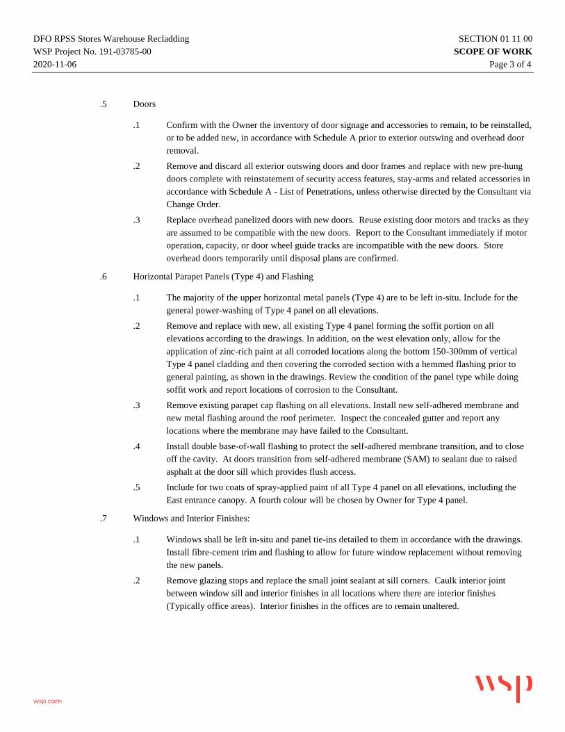
.5 Doors
.1 Confirm with the Owner the inventory of door signage and accessories to remain, to be reinstalled,
or to be added new, in accordance with Schedule A prior to exterior outswing and overhead door
removal.
.2 Remove and discard all exterior outswing doors and door frames and replace with new pre-hung
doors complete with reinstatement of security access features, stay-arms and related accessories in
accordance with Schedule A - List of Penetrations, unless otherwise directed by the Consultant via
Change Order.
.3 Replace overhead panelized doors with new doors. Reuse existing door motors and tracks as they
are assumed to be compatible with the new doors. Report to the Consultant immediately if motor
operation, capacity, or door wheel guide tracks are incompatible with the new doors. Store
overhead doors temporarily until disposal plans are confirmed.
.6 Horizontal Parapet Panels (Type 4) and Flashing
.1 The majority of the upper horizontal metal panels (Type 4) are to be left in-situ. Include for the
general power-washing of Type 4 panel on all elevations.
.2 Remove and replace with new, all existing Type 4 panel forming the soffit portion on all
elevations according to the drawings. In addition, on the west elevation only, allow for the
application of zinc-rich paint at all corroded locations along the bottom 150-300mm of vertical
Type 4 panel cladding and then covering the corroded section with a hemmed flashing prior to
general painting, as shown in the drawings. Review the condition of the panel type while doing
soffit work and report locations of corrosion to the Consultant.
.3 Remove existing parapet cap flashing on all elevations. Install new self-adhered membrane and
new metal flashing around the roof perimeter. Inspect the concealed gutter and report any
locations where the membrane may have failed to the Consultant.
.4 Install double base-of-wall flashing to protect the self-adhered membrane transition, and to close
off the cavity. At doors transition from self-adhered membrane (SAM) to sealant due to raised
asphalt at the door sill which provides flush access.
.5 Include for two coats of spray-applied paint of all Type 4 panel on all elevations, including the
East entrance canopy. A fourth colour will be chosen by Owner for Type 4 panel.
.7 Windows and Interior Finishes:
.1 Windows shall be left in-situ and panel tie-ins detailed to them in accordance with the drawings.
Install fibre-cement trim and flashing to allow for future window replacement without removing
the new panels.
.2 Remove glazing stops and replace the small joint sealant at sill corners. Caulk interior joint
between window sill and interior finishes in all locations where there are interior finishes
(Typically office areas). Interior finishes in the offices are to remain unaltered.

DFO RPSS Stores Warehouse Recladding SECTION 01 11 00
WSP Project No. 191-03785-00 SCOPE OF WORK
2020-11-06 Page 4 of 4
wsp.com
1.5 OWNER OCCUPANCY
.1 Owner will occupy premises during entire construction period for execution of normal operations. Execute work
with least possible interference or disturbance to occupants and normal use of premises. Arrange with Consultant to
facilitate execution of work.
.2 Co-operate with Owner in scheduling operations to minimize conflict and to facilitate Owner usage.
.3 Ensure that the building and work area is secure at the end of each work day to the satisfaction of the Owner.
1.6 EXISTING SERVICES
.1 Notify, Consultant and utility companies of intended interruption of services and obtain required permission.
.2 Establish location and extent of service lines in area of work before starting Work. Notify Consultant of findings.
.3 Submit schedule to and obtain approval from Consultant for any shut-down or closure of active service or facility
including power and communications services. Adhere to approved schedule and provide notice to affected parties.
.4 Provide temporary services when directed by Consultant to maintain critical building and tenant systems.
.5 Where unknown services are encountered, immediately advise Consultant and confirm findings in writing.
END OF SECTION 01 11 00

SCHEDULE A - LIST OF EXTERIOR WALL PENETRATIONS SECTION 01 11 01ISSUED FOR
TENDER
INDEX CATEGORYDESCRIPTION
Function, Construction: ConditionAPPROX. QTY.
DRAWING REFERENCE
(REFER TO BE3.00 SERIES)BASE BID SCOPE DETAIL DWG REF.
1 Exterior Doors Exterior single door, Metal Outswing: Fair 1 N13
Door: Replace with newSill: Replace with newFrame: Replace with newSecurity: No Fob, Install Deadbolt Signage: NoneHandle: External: Handle Set with trigger; Internal: Push bar. Stay-arm: ClosureSweep: Exterior commercial grade aluminum
5.01
2 Exterior Doors Exterior single door, Metal Outswing: Fair 1 N14
Door: Clean, Repaint (2 coats)Frame: Clean, Repaint (2 coats)Sill: LeaveSecurity: No Fob, Install DeadboltSignage: See Item 43 - SignageHandle: Leave existingStay-arm: ClosureSweep: Exterior commercial grade aluminum
5.01
3 Exterior Doors Exterior single door, Metal Outswing: Fair 1 N15
Door: Replace with newSill: Replace with newFrame: Replace with newSecurity: No Fob, Install Deadbolt Signage: NoneHandle: External: Handle Set with trigger; Internal: Push bar. Stay-arm: ClosureSweep: Exterior commercial grade aluminum
5.01
4 Exterior Doors Exterior single door, Metal Outswing: Fair 1 S18
Door: Replace with newSill: Replace with newFrame: Replace with newSecurity: Fob access to remain Signage: See Item 43 - SignageHandle: External: Handle Set with trigger; Internal: Push bar. Stay-arm: ClosureSweep: Exterior commercial grade aluminum
5.01
5 Exterior Doors Exterior single door, Metal Outswing: Fair 1 S21
Door: Replace with newSill: Replace with newFrame: Replace with newSecurity: No Fob, Install Deadbolt Signage: See Item 43 - SignageHandle: External: Handle Set with trigger; Internal: Push bar. Stay-arm: ClosureSweep: Exterior commercial grade aluminum
5.01
6 Exterior Doors Exterior single door, Metal Outswing: Fair 1 S22
Door: Replace with new, store existing for reuse by ClientSill: Replace with newFrame: Replace with newSecurity: No Fob, Install Deadbolt Signage: NoneHandle: External: Handle Set with trigger; Internal: Push bar. Stay-arm: ClosureSweep: Exterior commercial grade aluminum
5.01

SCHEDULE A - LIST OF EXTERIOR WALL PENETRATIONS SECTION 01 11 01ISSUED FOR
TENDER
INDEX CATEGORYDESCRIPTION
Function, Construction: ConditionAPPROX. QTY.
DRAWING REFERENCE
(REFER TO BE3.00 SERIES)BASE BID SCOPE DETAIL DWG REF.
7 Exterior Doors Exterior single door, Metal Outswing with glass inset: Poor 1 W13
Door: Replace with new, like-for -likeSill: Replace with newFrame: Replace with newSecurity: Fob access to remain Signage: NoneHandle: External: Handle Set with trigger; Internal: Push bar. Stay-arm: ClosureSweep: Exterior commercial grade aluminum
5.01
8 Exterior Doors Exterior single door, Metal Outswing with glass inset: Fair 1 W14
Door: Clean, Repaint (2 coats)Frame: Clean, Repaint (2 coats)Sill: LeaveSecurity: Fob access to remain Signage: NoneHandle: External: Handle Set with trigger; Internal: Push bar. Stay-arm: ClosureSweep: Exterior commercial grade aluminum
5.01
9 Exterior Doors Exterior single door, Metal Outswing: Poor 6 W15-W20
Door: Replace with newSill: Replace with newFrame: Replace with newSecurity: No Fob, Install Deadbolt Signage: NoneHandle: External: Handle Set with trigger; Internal: Push bar. Stay-arm: ClosureSweep: Exterior commercial grade aluminum
5.01
10 Exterior Doors Exterior double door for Mechanical Room, Metal Outswing: Poor 1 E11
Door: Replace with newSill: Replace with newFrame: Replace with newSecurity: No Fob, Install DeadboltSignage: NoneHandle: External: Handle Set with trigger; Internal: Push bar. Stay-arm: closure, ability to lock in 'open' positionSweep: Exterior commercial grade aluminum
5.01 sim
11 Exterior Doors Exterior double door for Electrical Room, Metal Outswing: Fair 1 E12
Door: Clean, Repaint (2 coats)Frame: Clean, Repaint (2 coats)Sill: LeaveSecurity: No Fob, Install DeadboltSignage: NoneHandle: External: Handle Set with trigger; Internal: Push bar. Stay-arm: closure, ability to lock in 'open' positionSweep: Exterior commercial grade aluminum
5.01 Sim
12 Exterior DoorsExt. double-glazed aluminum door, Outswing, Fair
1 E13 Waterproof in-Situ. 5.01 Sim
13 Exterior Doors Loading overhead door, Overhead, 8x2ft wide panels, uninsulated, RO=10ft: Poor 1 N16
Door: Replace with new c/w 2x viewing slots at 5ft heightRails: Replace with newMotor: Reuse/reconnect to ExistingSafety: Relocate laser detection from 600mm (2ft) to 200mm (8in.) above top of slab.Signage: See Item 43 - SignageVisibility: See Item 23 - Site Safety
5.02

SCHEDULE A - LIST OF EXTERIOR WALL PENETRATIONS SECTION 01 11 01ISSUED FOR
TENDER
INDEX CATEGORYDESCRIPTION
Function, Construction: ConditionAPPROX. QTY.
DRAWING REFERENCE
(REFER TO BE3.00 SERIES)BASE BID SCOPE DETAIL DWG REF.
14 Exterior Doors Loading overhead door, Overhead, 8x2ft wide panels, uninsulated, RO=8ft.: Poor 1 N17
Door: Replace with new c/w 2x viewing slots at 5ft heightRails: Replace with newMotor: Reuse/reconnect to ExistingSafety: Relocate laser detection from 600mm (2ft) to 200mm (8in.) above top of slab.Signage: See Item 43 - SignageVisibility: See Item 23 - Site SafetyNote: Exterior metal flashing to be 12GA steel. Client to install new truck bumper system and extend ramp
5.02
15 Exterior Doors Loading overhead door, Overhead, 8x2ft wide panels, uninsulated, RO=8ft: Poor 1 S19
Door: Replace with new c/w 2x viewing slots at 5ft heightRails: Replace with newMotor: Reuse/reconnect to ExistingSafety: Relocate laser detection from 600mm (2ft) to 200mm (8in.) above top of slab.Signage: See Item 43 - SignageVisibility: See Item 23 - Site Safety
5.02
16 Exterior Doors Loading overhead door, Overhead, 8x2ft wide panels, uninsulated, RO=8ft: Poor 1 S26
Door: Replace with new c/w 2x viewing slots at 5ft heightRails: Replace with newMotor: Reuse/reconnect to ExistingSafety: Relocate laser detection from 600mm (2ft) to 200mm (8in.) above top of slab.Signage: See Item 43 - SignageVisibility: See Item 23 - Site Safety
5.02
17 Windows 2x2ft Ganged Fixed Windows, Ribbon Glazing: Fair() Indicates number of IGUs per window group
5N8 (6), N9 (5), S23 (4),
E14 (3), E15 (6)Waterproof in Situ. Remove sealant at sill ends and apply small joint/silicone sealant to seal joint.
5.03 Sim
18 Windows Punched window, Operable Slider: Fair 5 N10-N12, W11,W12Waterproof in-situ. Remove sealant at sill ends and apply small joint/silicone sealant to seal joint.
5.03 Sim
19 Fire Safety Water Gong, Wall-mounted (Panel Type 4): Poor 1 S11 Remove and Reinstall. 4/4.04
20 Fire Safety Emergency Strobe Lighting, wall-mounted (Panel Type 1): Poor 1 E6 Replace with new. 4/4.04
21 Fire Safety Fire Suppression Pipe penetrations, Wall-mounted (Panel Type 1): Fair to Good 2 S12, S35 Waterproof in-Situ. Clean, Repaint (2 coats) 2/4.0422 Site Safety Muster Station Log Book Box, Wall-mounted (Panel Type 1): Good 1 W9 Remove and Reinstall. 4/4.04
23 Site Safety Safety Visibility Strips, Wall-mounted, Good 8N22, N23, N24, N25S24, S25, S41, S42
Remove and Replace with new. N/A
24 Mechanical Pipe penetrations, Wall-mounted (Panel Type 1): Poor 3 S14, S15, S16 Permanently Remove. Do not Reinstall. N/A
25 Mechanical Pipe penetrations, Wall-mounted (Panel Type 1): Poor 2 S27, S43 Waterproof in-Situ. Clean, Repaint (2 coats) 2B/4.04
26 Mechanical Duct Louver, Wall-mounted (Panel Type 4): Fair 1 N18 Excluded from Scope. N/A
27 Mechanical Duct Louver,Wall-mounted (Panel Type 4): Fair 4 S10, E3, E4, E5 Replace with new. 3/4.04
28 Mechanical Hooded Exhaust Fan, Wall-mounted (Panel Type 1): Good 1 S9 Remove and Reinstall. 1/4.04
29 Mechanical Natural Gas Pipe penetrations, Wall-mounted (Panel Type 1): Fair 4 S13, E7, E8, E19Waterproof in-Situ. E7 and E8 are Gas Supplier responsibility. Clean, Repaint S13 and E19 (2 coats)
2/4.04
30 Drainage 4x2-inch Rainwater Leaders and Drains, Wall-mounted (Panel Type 1): Poor 7 N26-N28, S37-S39, E10Replace with new. E10 to be replaced outside of cladding. Bracket fasteners to be sealed.
N/A
SCHEDULE A - LIST OF EXTERIOR WALL PENETRATIONS SECTION 01 11 01ISSUED FOR
TENDER
INDEX CATEGORYDESCRIPTION
Function, Construction: ConditionAPPROX. QTY.
DRAWING REFERENCE
(REFER TO BE3.00 SERIES)BASE BID SCOPE DETAIL DWG REF.
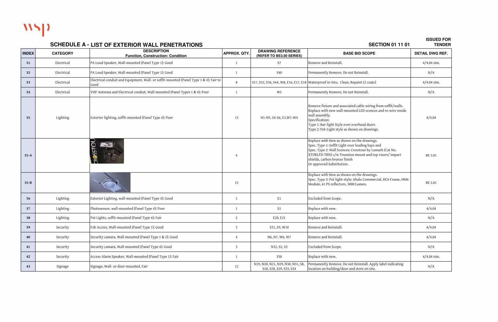
31 Electrical PA Loud Speaker, Wall-mounted (Panel Type 1): Good 1 S7 Remove and Reinstall. 4/4.04 sim.
32 Electrical PA Loud Speaker, Wall-mounted (Panel Type 1): Good 1 S40 Permanently Remove. Do not Reinstall. N/A
33 ElectricalElectrical conduit and Equipment, Wall- or soffit-mounted (Panel Type 1 & 4): Fair to Good
8 S17, S32, S36, S44, W8, E16, E17, E18 Waterproof in-Situ. Clean, Repaint (2 coats) 4/4.04 sim.
34 Electrical VHF Antenna and Electrical conduit, Wall-mounted (Panel Types 1 & 4): Poor 1 W5 Permanently Remove. Do not Reinstall. N/A
35 Lighting Exterior lighting, soffit-mounted (Panel Type 4): Poor 13 N1-N5, S4-S6, E2,W1-W4
Remove fixture and associated cable wiring from soffit/walls. Replace with new wall-mounted LED sconces and re-wire inside wall assembly.Specification: Type 1: Bar-light Style over overhead doorsType 2: Pot-Light style as shown on drawings.
4/4.04
35-A 4
Replace with New as shown on the drawings.Spec. Type 1: Soffit Light over loading bays andSpec. Type 2: Wall Sconces: Crosstour by Lumark (Cat No. XTORLFD-TRN) c/w Trunnion mount and top visors/ impact shields, carbon bronze finishOr approved Substitution.
BE 2.01
35-B 15
Replace with New as shown on the drawings.Spec. Type 3: Pot light-style: Ahalo Commercial, HC6 Frame, HM6 Module, 61 PS reflectors, 3000 Lumen. BE 2.01
36 Lighting Exterior Lighting, wall-mounted (Panel Type 4): Good 1 E1 Excluded from Scope. N/A
37 Lighting Photosensor, wall-mounted (Panel Type 4): Poor 1 S1 Replace with new. 4/4.04
38 Lighting Pot Lights, soffit-mounted (Panel Type 4): Fair 2 E20, E21 Replace with new. N/A
39 Security Fob Access, Wall-mounted (Panel Type 1): Good 3 S31, E9, W10 Remove and Reinstall. 4/4.04
40 Security Security camara, Wall-mounted (Panel Type 1 & 2): Good 4 N6, N7, W6, W7 Remove and Reinstall. 4/4.04
41 Security Security camara, Wall-mounted (Panel Type 4): Good 3 N32, S2, S3 Excluded from Scope. N/A
42 Security Access Alarm Speaker, Wall-mounted (Panel Type 1): Fair 1 S30 Replace with new. 4/4.04 sim.
43 Signage Signage, Wall- or door-mounted, Fair 12N19, N20, N21, N29, N30, N31, S8,
S20, S28, S29, S33, S34Permanently Remove. Do not Reinstall. Apply label indicating location on building/door and store on site.
N/A

DFO RPSS Stores Warehouse Recladding SECTION 01 33 00
WSP Project No. 191-03785-00 SUBMITTALS PROCEDURE
2020-11-06 Page 1 of 2
wsp.com
1.1 ADMINISTRATIVE
1.1.1 Submit to Consultant submittals listed for review. Ensure the projects listed in Schedule A form part of the
submittals list. Prepare a complete products list and confirm with the Owner and Consultant which products require
a physical object to be submitted in addition to digital documentation. Submit promptly and in orderly sequence to
not cause delay in Work. Failure to submit in ample time is not considered sufficient reason for extension of
Contract Time and no claim for extension by reason of such default will be allowed.
1.1.2 Do not proceed with Work affected by submittal until review is complete.
1.1.3 Present shop drawings, product data, samples and mock-ups in SI Metric units.
1.1.4 Where items or information is not produced in SI Metric units converted values are acceptable.
1.1.5 Review submittals prior to submission to Consultant. This review represents that necessary requirements have been
determined and verified, or will be, and that each submittal has been checked and co-ordinated with requirements of
Work and Contract Documents. Submittals not stamped, signed, dated and identified as to specific project will be
returned without being examined and are considered rejected.
1.1.6 Notify Consultant, in writing at time of submission, identifying deviations from requirements of Contract
Documents stating reasons for deviations.
1.1.7 Verify field measurements and affected adjacent Work are co-ordinated.
1.1.8 Contractor's responsibility for errors and omissions in submission is not relieved by Consultant's review of
submittals.
1.1.9 Contractor's responsibility for deviations in submission from requirements of Contract Documents is not relieved by
Consultant review.
1.1.10 Keep one reviewed copy of each submission on site.
1.2 PRODUCT DATA
1.2.1 Submit electronic copies of product data sheets or brochures for requirements requested in specification Sections and
as requested by Consultant where shop drawings will not be prepared due to standardized manufacture of product.
1.2.2 Submit electronic copies of test reports for requirements requested in specification Sections and as requested by
Consultant.
1.2.2.1 Submit reports signed by authorized official of testing laboratory that material, product or system to be
used has been tested in accord with specified requirements.
1.2.2.2 Testing must have been within five (5) years of date of contract award for project.
1.2.3 Submit electronic copies of manufacturers instructions for requirements requested in specification Sections and as
requested by Consultant.
1.2.3.1 Pre-printed material describing installation of product, system or material, including special notices and
Material Safety Data Sheets concerning impedances, hazards and safety precautions.
1.2.4 Submit electronic copies of Manufacturer's Field Reports for requirements requested in specification Sections and as
requested by Consultant.
1.2.5 Submit electronic copies of Operation and Maintenance Data for requirements requested in specification Sections
and as requested by Consultant.

DFO RPSS Stores Warehouse Recladding SECTION 01 33 00
WSP Project No. 191-03785-00 SUBMITTALS PROCEDURE
2020-11-06 Page 2 of 2
wsp.com
1.2.6 Delete information not applicable to project.
1.2.7 Supplement standard information to provide details applicable to project.
1.3 SAMPLES
1.3.1 Submit for review samples as requested by the Consultant.
1.3.2 Notify Consultant in writing, at time of submission of deviations in samples from requirements of Contract
Documents.
1.3.3 Where colour, pattern or texture is criterion, submit full range of samples.
1.3.4 Adjustments made on samples by Consultant are not intended to change Contract Price. If adjustments affect value
of Work, state such in writing to Consultant at the time the product is submitted and prior to proceeding with Work.
1.3.5 Make changes in samples which Consultant may require, consistent with Contract Documents.
1.3.6 Reviewed and accepted samples will become standard of workmanship and material against which installed Work
will be verified.
1.4 MOCK-UPS
1.4.1 Erect mock-ups as requested by Consultant.
1.4.2 Mockups anticipated include but are not limited to: window, outswing door, overhead door, each penetration type,
and an integrated panel-to-panel type mockup.
1.5 PHOTOGRAPHIC DOCUMENTATION
1.5.1 Frequency of photographic documentation: as requested by Consultant. If work is covered up prior to consultant
review, take representative photos with a resolution no less than 1 MB per photo.
1.6 CERTIFICATES AND TRANSCRIPTS
1.6.1 Immediately after award of Contract, submit Workers' Compensation Board status.
1.6.2 Submit transcription of insurance immediately after award of Contract.
2 PRODUCTS
2.1 NOT USED
3 EXECUTION
3.1 NOT USED
END OF SECTION 01 33 00

DFO RPSS Stores Warehouse Recladding SECTION 02 41 13
WSP Project No. 191-03785-00 SELECTIVE DEMOLITION
2020-11-06 Page 1 of 5
wsp.com
1.0 GENERAL
1.1 SUMMARY
.1 Section includes descriptions for demolishing, salvaging, recycling and removing site work items identified for
removal in whole or in part from site demolition activities.
.2 Demolition involves temporary relocation or removal of security cameras, lighting, fobs, swipe cards which are to
remain functional during the course of the work.
.3 Demolition involves removal of metal panel types 1, 2 and 3, panels on the east entrance, as well as outswing and
overhead doors and roof parapet flashing. It does not include for the removal of metal panel type 4 or windows.
.4 It is assumed the 1.5inch thick polyethylene-faced batt insulation that is sandwiched between the metal panels and
the steel backup framing is to be left in place and repaired. Care shall be taken to adhere batt in place prior to
removing panels whose fasteners likely secure the batts in place. Perform a mock-up to test the demolition
procedure.
.5 The Hazardous Materials Report dated March 18, 2019 references known hazards reported by the Owner which
shall be mitigated and disposed of as part of the fixed fee. The Contractor remains responsible for identifying and
testing, at their cost, any other unknown hazards identified during construction. If materials discovered are found to
be hazardous, payment for additional Safe Work Procedures, and mitigation and disposal of such additional hazards,
shall be negotiated with and paid for by the Owner at that time.
.6 It is the Owner’s expectation that a section of the existing panels will be removed and new panels reinstalled,
including penetration and door detailing, by the end of each working day to maintain a safe and secure building
envelope. The Contractor may develop alternate, equivalent and more economical means of achieving this
requirement provided it is approved by the Owner and Consultant.
.7 This is an oceanside site. Ensure all materials new and existing slated for removal cannot leach or can be blown into
the ground or the water.
1.2 RELATED REQUIREMENTS
.1 Section 01 00 00 – General Requirements.
.2 Section 00 41 02 - Hazardous Materials Report by Stantec dated March 18, 2019 (169 pgs) (Under Separate cover)
1.3 REFERENCE STANDARDS
.1 British Columbia Building Code, Part 8 - Safety Measures at Construction and Demolition Site.
.2 WorkSafe BC Occupational Health and Safety Policies and Regulations.
.3 CSA S350-M1980 (R2003) - "Code of Practice for Safety in Demolition of Structure."
1.4 PRE-DEMOLITION HAZARDOUS MATERIALS SURVEY
.1 The pre-demolition hazardous materials survey report was prepared for this project for your review and information,
and are available under separate cover. Panel Types do contain lead-based paint. The report is confidential.
.1 Hazardous Materials Report by Stantec dated March 18, 2019 (169 pgs)
1.5 DEFINITIONS
.1 Selective Demolition: Sequencing demolition activities to allow separation and sorting of selected site materials.
.2 Hazardous Substances: dangerous substances, dangerous goods, hazardous commodities and hazardous products,
including but not limited to: asbestos PCB's, CFC's, HCFC's poisons, corrosive agents, flammable substances,
ammunition, explosives, radioactive substances, or other material that can endanger human health or well being or
environment if handled improperly.

DFO RPSS Stores Warehouse Recladding SECTION 02 41 13
WSP Project No. 191-03785-00 SELECTIVE DEMOLITION
2020-11-06 Page 2 of 5
wsp.com
.3 Waste Management Coordinator (WMC): Contractor’s representative responsible for supervising waste
management activities as well as coordinating related, required submittal and reporting requirements.
.4 Construction Waste Management Plan (CWM Plan): Written plan addressing opportunities for reduction, reuse, or
recycling of materials prepared in accordance with Section 01 74 19- Waste Management and Disposal.
.5 Construction Waste Management Report (CWM Report): Written report identifying actual materials that formed
CWM Plan for reduction, reuse, or recycling of materials
1.6 ADMINISTRATIVE REQUIREMENTS
.1 Coordination: Coordinate with Owner for the material ownership including the following:
.1 Except for items or materials indicated to be reused, salvaged, reinstalled, or otherwise indicated to remain
Owner 's property, demolished materials shall become Contractor’s property and shall be removed from
Project site.
.2 Pre-Demolition Meetings.
.1 Convene pre-installation meeting with Consultant and Owner before beginning work.
.1 Verify project requirements.
.2 Verify existing site conditions adjacent to demolition work
.3 Coordinate with other construction sub trades
.4 Examine existing site conditions adjacent to demolition work, prior to start of Work
.5 Fuel is stored on this site. Communicate with the Owner regarding locations of dangerous
substances and communicate with all workers and subtrades the risks and preventative measures at
subsequent safety and orientation meetings.
.3 Scheduling:
.1 Employ necessary means to meet project time lines without compromising specified minimum rates of
material diversion.
.2 In event of unforeseen delay notify Consultant in writing.
1.7 QUALITY ASSURANCE
.1 Regulatory Requirements: ensure Work is performed in compliance with applicable Provincial regulations.
.2 Comply with hauling and disposal regulations of the Authority Having Jurisdiction.
1.8 SITE CONDITIONS
.1 Environmental protection:
.1 Ensure work does not adversely affect adjacent watercourses, groundwater and wildlife, or contribute to
excess air and noise pollution.
.2 Fires and burning of waste or materials is not permitted on site.
.3 Burying of rubbish waste materials is not permitted.
.4 Disposal of waste of volatile materials including but not limited to, mineral spirits, oil, petroleum-based
lubricants, or toxic cleaning solutions into watercourses, storm or sanitary sewers, is not permitted.
.5 Ensure proper disposal procedures are maintained throughout the project.
.2 Pumping of water containing suspended materials into watercourses, storm or sanitary sewers or onto adjacent
properties, is not permitted.
.3 Control disposal or runoff of water containing suspended materials or other harmful substances in accordance with
authorities having jurisdiction.

DFO RPSS Stores Warehouse Recladding SECTION 02 41 13
WSP Project No. 191-03785-00 SELECTIVE DEMOLITION
2020-11-06 Page 3 of 5
wsp.com
.4 Protect trees, plants and foliage on site and adjacent properties where indicated and as identified during pre-
construction review.
.5 Prevent extraneous materials from contaminating air beyond application area, by providing temporary enclosures
during demolition work.
.6 Cover or wet down dry materials and waste to prevent blowing dust and debris.
.7 Conduct selective site demolition so Owner's operations will not be disrupted:
.1 Provide not less than 72 hours' notice to Owner of activities that will affect operations.
.2 Maintain access to existing walkways, exits, and other adjacent occupied or used facilities:
.8 Consultant assumes no responsibility for Selective Site elements being demolished:
.9 Conditions existing at time of inspection for bidding purpose will be maintained by Owner as far as practical.
1.9 EXISTING CONDITIONS
.1 This contractor specification for WorkSafeBC, is to assist in managing the risks of contractor exposure to hazardous
materials while conducting decontamination and demolition work at the worksite. It does not absolve the Contractor
from following the regulatory requirements in force for this type of demolition work.
.2 This document does not cover all potential risks associated with this work, such as electrical hazards or falling from
heights hazards. Rather, this document specifically addresses the risk associated with disturbing hazardous
materials while performing this work, including worker exposure to hazardous materials, and improper handling or
disposal of such materials. This document is intended to be used in conjunction with the associated pre-demolition
hazardous materials surveys, appropriate Jurisdictions Having Authority, Contractors’ Health and Safety program,
and in accordance with WorkSafe BC Occupational Health and Safety Regulations. Specific written procedures
(exposure control plan, safe work procedures, etc.) will be the responsibility of the Contractor performing the work.
.3 If materials suspected of containing hazardous materials are encountered, do not disturb; immediately notify
Consultant. Hazardous materials will be removed by Owner under a separate contract or as a change to the Work.
.4 If material resembling spray- or trowel-applied asbestos or other designated substance listed as hazardous be
encountered in course of demolition, stop work, take preventive measures, and notify Consultant immediately.
Proceed only after receipt of written instructions have been received from Consultant.
1.10 PRE-DEMOLITION HAZARDOUS MATERIALS SURVEY
.1 A pre-demolition hazardous materials survey report dated March 18, 2019 prepared by Stantec and is available.
Disclosed substances in that report within the scope of work are considered known substances and measures to
mitigate or abate them are to be included in the Contractor’s fee and schedule.
.2 Findings for the Stores Warehouse Building, built in 1978, are found in Appendix 5.5 are summarized here for
convenience only. If there is a discrepancy between this wording and that in the Stantec report, the Stantec report
shall be considered correct and shall be the basis for the bid. Other products not tested due to lack of access or
because they were concealed should be considered hazardous unless proven otherwise. The contractor is
responsible for reviewing and understanding which materials within the scope of work are hazardous based on the
Survey report and conditions during demolition.
.1 1-2% Chrystophile found in offices and board room Drywall compound applied to walls and ceilings.
.2 32,000 ppm LCP (lead containing paint) on the metal panels coloured pink/ peach (Panel Types 2, 3).
.3 3,500ppm LCP (lead containing paint) on the metal panels coloured light blue/ grey (Panel Type 1).
.4 920 ppm LCP on structural steel coloured red.
.3 Hazardous materials which are flagged in this report may require special handling and/or disposal processes.
.4 Any contractor performing decontamination or demolition work on site should review these reports and become
familiar with its contents of this specification prior to performing work.
.5 Lead-Containing Paint on metal panels

DFO RPSS Stores Warehouse Recladding SECTION 02 41 13
WSP Project No. 191-03785-00 SELECTIVE DEMOLITION
2020-11-06 Page 4 of 5
wsp.com
.1 Assume the LCP on the metal panels is leachable such that special precautions must be taken and paid for
by the contractor. The Contractor may elect to test for leachability and notify the Consultant if testing
confirms the contrary. Remove the panels and store them such that inclement weather will not wash paint
chips or effluent containing LCP from the work or storage site. Dispose appropriately.
.2 Requisition and pay for leachability testing of the lead-containing paint. If the LCP results fall within
standard limitations for regular disposal, the Owner can claim the credit for not having to pay for a
premium for panel disposal.
1.11 COVID-19 ACCOMODATIONS
.1 The Contractor is fully-responsible for applying and paying for project-specific Safe Work Procedures in accordance
with WorkSafeBC guidelines relating to COVID-19, or the Owner’s guidelines, whichever is the more stringent.
.2 All Prime contractors and subcontractors shall submit to the Consultant their company’s safe work procedure(s)
prior to the start of demolition.
.3 The Contractor shall pay for and supply event-grade wash stations, one for every 15 workers on site at any time,
positioned sufficiently apart from each other. If WorkSafeBC guidelines for wash stations are more stringent, the
more stringent configurations shall apply.
.4 Regular site meetings shall be held in person provided only essential persons attend, and they can be 2 meters apart
wearing the appropriate PPE. The Contractor will confirm all parties attending agree to the terms of the meeting.
Otherwise, the Contractor will make provisions to hold the site meetings via video-conferencing.
.5 The Contractor is to have assumed to take reasonable measures into consideration when preparing their bid relating
to schedule and cost to implement WorkSafeBC recommendations such as safe physical distancing.
.6 Should the site be shut down or significantly affected by this disease, the Contractor will be responsible to secure
and make safe the site. Should the supply chain be significantly affected, the Contractor shall find another supply
chain or report efforts that one is not available or would be more disruptive than remaining with the existing
contractor. Consequences resulting from the shut down shall be disclosed by the Contractor and Owner, to the
Consultant, within 10 working days.
1.12 EQUIPMENT
.1 Equipment and Heavy Machinery:
.1 Machinery running only while in use, except where extreme temperatures prohibit shutting machinery
down.
.2 Ensure appropriate measures are taken when above or below utilities, services, or suspended parkade slabs.
.3 Coordinate with the Owner as they also use their own heavy machinery.
2.0 EXECUTION
2.1 EXAMINATION
.1 Survey existing conditions and correlate with requirements indicated to determine extent of selective site demolition
required.
.2 Consultant does not guaranty that existing conditions are the same as those indicated in Project Record Documents.
.3 Inventory and record the condition of items being removed and salvaged.
.4 When unanticipated mechanical, electrical, or structural elements are encountered, investigate and measure the
nature and extent of the element. Promptly submit a written report to Consultant.

DFO RPSS Stores Warehouse Recladding SECTION 02 41 13
WSP Project No. 191-03785-00 SELECTIVE DEMOLITION
2020-11-06 Page 5 of 5
wsp.com
2.2 STOCKPILING
.1 Designate appropriate security resources/measures to prevent vandalism, damage, injury and theft.
.2 Locate stockpiled materials convenient for use to eliminate double handling wherever possible.
.3 Stockpile materials designated for alternate disposal in location which facilitates removal from site and examination
by potential end markets, and which does not impede disassembly, processing, or hauling procedures.
.4 Do not stockpile materials so that you block the Owner’s operations. Relocation of such stockpiles will be at the
cost of the contractor.
2.3 RESTORATION
.1 Restore areas and existing works outside areas of demolition to conditions that existed prior to beginning of Work,
and to match condition of adjacent, undisturbed areas.
2.4 CLEANING
.1 Progress Cleaning: clean site weekly and before each weekend.
.1 Leave Work area tidy at end of each day.
.2 Remove debris, trim surfaces and leave work site clean, upon completion of Work
.3 Use cleaning solutions and procedures which are not harmful to health, are not injurious to plants, and do
not endanger wildlife, adjacent water courses or ground water.
.2 Final Cleaning: upon completion remove surplus materials, rubbish, tools and equipment.
END OF SECTION

DFO RPSS Stores Warehouse Recladding SECTION 06 10 53
WSP Project No. 191-03785-00 ROUGH CARPENTRY
2020-11-06 Page 1 of 2
wsp.com
1 GENERAL
1.1 SUMMARY
1. Section includes wood used for penetrations in exterior walls (if required), blocking used in the soffit for lighting
and used for shimming behind the fibre cement trim around windows, and other blocking.
2. Wood shall be preservative-treated with CCA, CA. Borate-based preservative is not acceptable.
1.2 RELATED REQUIREMENTS
1. Section 07 62 00 – Sheet Metal Flashing and Trim.
2. Section 07 45 00 – Fibre Cement Trim
3. Section 09 91 00 -- Painting
1.3 REFERENCES
1. ASTM A 493-95 (2004), “Standard Specification for Stainless Steel Wire and Wire Rods Cold Healing and Cold
Forging”.
2. ASTM F 1667-05, “Standard Specification for Driven Fasteners: Nails, Spikes and Staples”.
3. CSA B111-1974 (R2003), “Wire Nails, Spikes and Staples”.
4. CAN/CSA-G164-M92 (R2003), “Hot Dip Galvanizing or Irregularly Shaped Articles”.
5. National Lumber Grades Authority (NLGA) Standard Grading Rules for Canadian Lumber, 2007 edition.
1.4 SUBMITTALS
1. Submit samples of materials to the Consultant if requested.
2 PRODUCTS
2.1 MATERIALS
.1 Unless otherwise specified herein or directed by the Consultant, dimensions, thicknesses, of material must match
existing or be in accordance with Part 9 of the British Columbia Building Code as a minimum, whichever is the more
stringent.
.2 Conform to (NLGA) Standard Grading rules for Canadian lumber for the grades of lumber as specified herein.
.3 S4S unless otherwise specified. Moisture content not greater than 19% at time of installation of sheathing and building
paper.
2.2 WOOD FRAMING
.1 2" x 4" lumber: Pressure treated Hem-Fir, unincised, “No.2", “Standard”, “Stud” or “Construction” grade, kiln dry or
s-dry.
.2 Strapping: Plywood, Douglas Fir, "Sheathing" grade, pressure treated, 3/4" x 2".
.3 Blocking, Shims, Tapers: Hem-Fir, "Construction grade", pressure treated.
DFO RPSS Stores Warehouse Recladding SECTION 06 10 53
WSP Project No. 191-03785-00 ROUGH CARPENTRY
2020-11-06 Page 2 of 2
wsp.com
.4 Self Adhered Membrane: SBS modified asphalt, 40 mil thickness. Acceptable manufacturer: Blueskin SA by Bakor
or approved substitution.
2.3 NAILS, FASTENERS AND ACCESSORIES
.1 Framing Nails: In accordance with Part 9 of the British Columbia Building Code.
.2 Nails for Strapping: Hot dip, galvanized common nails, or stainless steel, minimum 2-1/2" long, to penetrate studs
min. 1".
.3 Screws for removeable boards: Ceramic coated or stainless-steel exterior screws, penetrate 1” min. into studs.
.4 Furring for removeable boards: 1/8” thick plastic shims, staggered, at 16” o.c., caulked to back side of wood.
.5 Stainless Steel Nails: Wire to conform to ASTM F1667, wire type SS 316.
.6 Stainless Steel screws: Wire to conform to ASTM A493, wire type SS 316 for wood, wire type SS 410 for self-tapping
screws.
.7 Sealant: Refer to Section 07 92 00 - Sealant.
.8 All fasteners exposed to weather shall be marine-grade and shall not corrode.
3 EXECUTION
3.1 WOOD FURRING AND BLOCKING
.1 Install wood spacer and support members as required to minimize exposure to rain. Paint all exposed wood.
.2 Align strapping with studs and fasten board through strapping and into studs.
3.2 ALUMINUM INSECT SCREEN SOFFIT
.3 Install rigid aluminum insect screen at soffits, provide a sample section following break to match profile shown in the
drawings to assess rigidity and sections’ ability to remain straight.
.4 Ensure rigid aluminum insect screen exists
3.3 HOARDING: WOOD-FRAMING BARRIERS AT EXITS
.1 Erect framing to create a protected pathway from doorways through the work area to the public, non-work area for
building occupants that is safe and sufficiently wide to maintain safe distancing.
.2 It is permitted to anchor one side to the Level 2 feature band provided the anchorage will be repaired to the satisfaction
of the Owner.
3.4 RAIN WATER MANAGEMENT
.1 Install sleeves for rain water leaders to carry water off the area of work and keep surface dry.
END OF SECTION 06 10 53

DFO RPSS Stores Warehouse Recladding SECTION 07 41 13
WSP Project No. 191-03785-00 PROFILED METAL CLADDING
2020-11-06 Page 1 of 7
wsp.com
1.0 GENERAL
1.1 SECTION INCLUDES
.1 Profiled metal wall cladding, flashing, trims, closures, fasteners, and accessories.
.2 Cladding insulation
1.2 RELATED SECTIONS
.1 Section 07 62 00 – Sheet Metal Flashing and Trim
.2 Section 07 92 00 – Sealants: Sealants between cladding and dissimilar construction.
1.3 REFERENCES
.1 CAN/CSA-S136-01 (R2007), "North American Specification for the Design of Cold-Formed Steel Structural
Members".
.2 Canadian Sheet Steel Building Institute (CSSBI) Sheet Steel Facts #6 and CSSBI Standard 20M-99, “Standard for
Sheet Steel Cladding for Architectural, Industrial and Commercial Building Applications”.
.3 National Building Code of Canada
.4 RCABC Roofing Practices Manual, current edition
.5 SMACNA manual, current edition
1.4 DESIGN REQUIREMENTS
.1 Design the structural properties of the system in accordance with CAN/CSA-S136 and the Canadian Sheet Steel
Building Institute Standards.
.2 Maximum deflection of spans not to exceed 1/180.
.3 Calculate wind, wind uplift, and snow loads in accordance with Part 4.0 of the British Columbia Building Code.
.4 Provide for thermal movement of components as may be caused by a temperature range in accordance with the British
Columbia Building Code, local temperature range 2½%, without harmful or unsightly buckling, failure of joint seals
or undue stress on anchors, fasteners.
.5 Allow for movement in cladding caused by deflection in structure.
.6 The panel not to exhibit any permanent deformation when subjected to design forces specified herein.
.7 Fasten the panel assembly to the building structure in a manner which transmits all loads to the main structure without
exceeding the capacity of any fastener.
1.5 SUBMITTALS
.1 Product Data: Manufacturer's product literature for the panel specified
.2 Product certificates signed by manufacturer certifying materials comply with the specified performance characteristics and
criteria, and physical requirements.
.3 Samples for verification: Provide material samples. Samples shall involve normal color and texture variations, include
sample sets showing the full range of variations expected.
.4 Submit sample of sealant for colour selection.
DFO RPSS Stores Warehouse Recladding SECTION 07 41 13
WSP Project No. 191-03785-00 PROFILED METAL CLADDING
2020-11-06 Page 2 of 7
wsp.com
1.6 QUALITY ASSURANCE
.1 Manufacturer Qualifications: Minimum of 10 years of experience in manufacturing exterior wall panels similar to
those specified.
.2 Employ workers having a minimum of five (5) years proven experience in this type of work and approved by the
manufacturer for installation of its products.
.3 Acceptable to manufacturer. If requested, submit evidence of having successfully completed panel assemblies of
design and size similar to this project within the preceding five (5) years.
1.7 DELIVERY, STORAGE AND HANDLING
.1 Deliver materials to the site and handle and store in original packages with the manufacturer's seals and labels intact.
.2 Observe proper handling procedures during fabrication, delivery and installation to prevent damage. Repair damaged
materials or replace at no additional cost to the Owner.
.3 Store cladding under cover and raised above ground to prevent damage from rust or abuse and keep from dampness
and extremes of the elements until the cladding is required for installation.
1.8 ENVIRONMENTAL REQUIREMENTS
.1 Ensure that environmental conditions for the installation of materials are within the limits prescribed by the
manufacturer of the product.
1.9 MAINTENANCE
.1 Submit the manufacturer's documentation covering the care, cleaning and maintenance of materials for incorporation
into maintenance manuals.
1.10 WARRANTY
.1 Project warranty refers to Conditions of the Contract for project warranty provisions. Manufacturer’s warranty:
submit, for Owner’s acceptance, manufacturer’s standard warranty documents executed by authorized company
official. Manufacturer’s warranty is in addition to, and not a limitation of, other rights owner may have under Contract
Documents.
.2 The Contractor shall warrant the materials to be free of faults and defects for a period of 10 years in accordance with
the General Requirements, except that the warranty shall be extended by paint manufacturer's standard multi-year
warranty. The warranty shall be in writing and shall be signed by the manufacturer.
2.0 PRODUCTS
2.1 METAL PANELS The Owner is flexible regarding sourcing of the profiled metal panels. Two panel classes are required:
.1 Class 1: Panel Type 1 (main field): 36” wide panels with exterior fasteners.
.2 Class 2: Panel Types 2 and 3 (at offices, guard room): 12” panels with concealed fasteners.
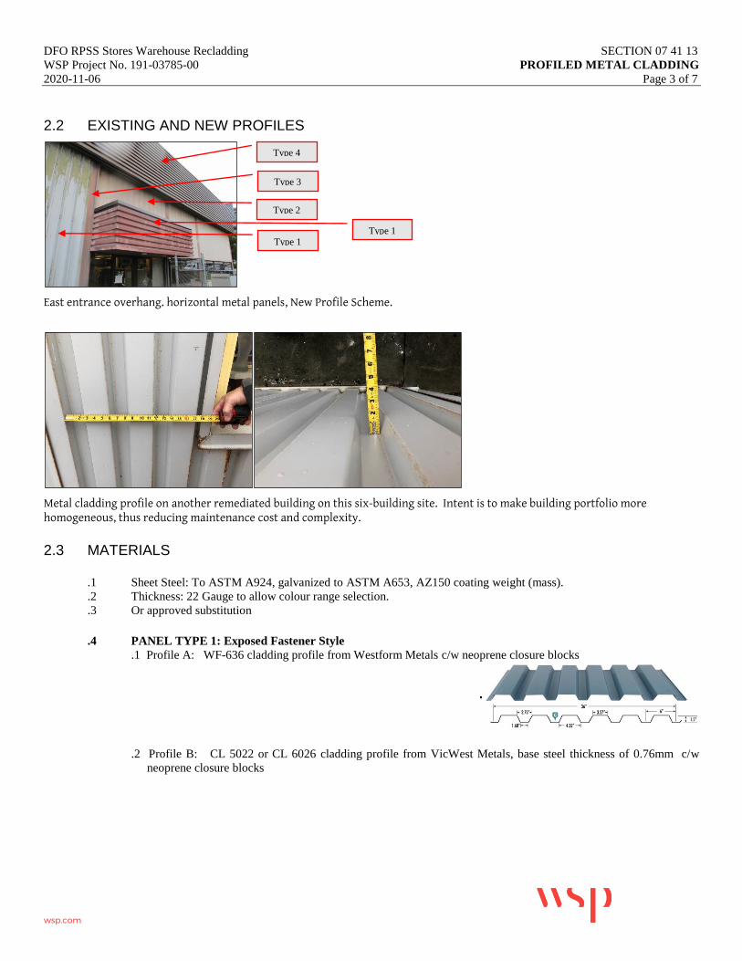
DFO RPSS Stores Warehouse Recladding SECTION 07 41 13
WSP Project No. 191-03785-00 PROFILED METAL CLADDING
2020-11-06 Page 3 of 7
wsp.com
2.2 EXISTING AND NEW PROFILES
East entrance overhang. horizontal metal panels, New Profile Scheme.
Metal cladding profile on another remediated building on this six-building site. Intent is to make building portfolio more homogeneous, thus reducing maintenance cost and complexity.
2.3 MATERIALS
.1 Sheet Steel: To ASTM A924, galvanized to ASTM A653, AZ150 coating weight (mass).
.2 Thickness: 22 Gauge to allow colour range selection.
.3 Or approved substitution
.4 PANEL TYPE 1: Exposed Fastener Style
.1 Profile A: WF-636 cladding profile from Westform Metals c/w neoprene closure blocks
.2 Profile B: CL 5022 or CL 6026 cladding profile from VicWest Metals, base steel thickness of 0.76mm c/w
neoprene closure blocks
Type 4
Type 1
Type 2
Type 3
Type 1

DFO RPSS Stores Warehouse Recladding SECTION 07 41 13
WSP Project No. 191-03785-00 PROFILED METAL CLADDING
2020-11-06 Page 4 of 7
wsp.com
.3 Fastener: Marine-grade, corrosion-resistant, as recommended by manufacturer
.4 Gauge: 24ga. AZ 150 Galvanized steel
.5 Finish: Fluorothane Coastal
.6 Colour: Colour type #1, to be determined by Owner from 24 Gauge Colour Chart
Westform Metals Colour Pallette
.5 PANEL TYPE 2: Concealed Fastener Style
.1 Profile: AD 200-R/SR or others listed below, as manufactured by VicWest Metals c/w neoprene closure blocks
.2 Fastener: Hidden, HGD steel, Marine Grade.
.3 Gauge: 22 ga. AZ 150 Galvanized steel \
.4 Finish: Fluorothane Coastal
.5 Colour: Colour type #2, to be determined by Owner
.6 PANEL TYPE 3 Concealed Fastener Style
.1 Profile: Similar to Panel Type 2
.2 Fastener: Match Panel Type 2
.3 Gauge: Match Panel Type 2
.4 Finish: Fluorothane Coastal
.5 Colour: Colour type #3, to be determined by Owner

DFO RPSS Stores Warehouse Recladding SECTION 07 41 13
WSP Project No. 191-03785-00 PROFILED METAL CLADDING
2020-11-06 Page 5 of 7
wsp.com
.7 PANEL TYPE 4A -RESERVED- Sourcing and matching panel type 4 may not be required. Depending on the
condition of the section of this panel identified in the drawings, and as discovered elsewhere during the Work.
.1 Profile: Similar to Panel Type 4
.2 Fastener: TBD
.3 Gauge: TBD
.4 Finish: TBD
.5 Colour: Closely Match Panel Type 4.
2.4 CLADDING INSULATION
.1 Fibreglass matt insulation
.1 As required on site and as directed by the Consultant, remove and discard existing polyester-faced fibreglass batts
and replace fibreglass batt with a low-permeance, metallized polypropylene facer with tri-directional fibreglass/
Polyethylene reinforcement. Seal lap joints.
.2 Laminated thickness shall have the following characteristics:
.1 To match existing and provide R7.5 ci (RSI 1.3ci) minimum
.2 Permeance of the facer on the inside of the insulation shall be not greater than 0.05 perms (2.875 ng/N.s
(ASTM E96, Procedure A.) A breathable facer on the exterior is permitted.
.2 Spray-applied polyurethane insulation (SPUF)
.1 Install medium density SPUF in targeted fashion to air and weather seal penetrations from the interior. Limit the
amount of combustible material used, relying on the existing insulation continuity wherever possible.
.2 Foam to have the following characteristics:
.3 To match existing and provide R7.5 ci (RSI 1.3ci) minimum
.3 Acceptable Products larger applications:
.4 Polar Foam PF-7300-0 SOYA by Demilec Inc
.5 Walltite ECO by BASF
.4 Acceptable Products for smaller application around penetrations:
.6 CF 812 WD low pressure door and window foam by HILTI
.7 GreatStuff for Windows & Doors minimal-expanding polyurethane foam BY GREAT STUFF™
2.5 CLADDING COMPONENTS / ACCESSORIES
.1 Flatstock metal flashing for use behind panel at penetrations, interior and exterior corners: 26 gauge prefinished metal.
.2 Flashing, Trim: Sheet steel to ASTM A924, minimum 24-gauge, galvanized to ASTM A653, Z275 (G90) (mass),
prefinished to match face sheets.
.3 Exposed Fasteners: Manufacturer's standard corrosion-resistant type to suit application; size, spacing to withstand full
design loading. Use neoprene washers under fasteners. The exposed fasteners in exterior panel to match panel colour.
SELF-TAPPING SCREWS Carbon Steel, Zinc – Chromate Plated, or stainless steel, Neoprene Washer, 3/8″ Hex.
Head.
.4 Concealed Fasteners: Manufacturer's standard corrosion-resistant type to suit application; size, spacing to withstand full

DFO RPSS Stores Warehouse Recladding SECTION 07 41 13
WSP Project No. 191-03785-00 PROFILED METAL CLADDING
2020-11-06 Page 6 of 7
wsp.com
design loading.
.5 Sealant: In accordance with Section 07 92 00.
.6 Rubber Gaskets, Metal Closures: Cladding manufacturer’s standard for specific application and use and as detailed.
2.6 FABRICATION
.1 Exterior Sheet: Machine Formed, galvanized metal, prefinished colour, profile as specified herein.
.2 Tolerances
1. Panel dimensions shall be such that there will be an allowance for field adjustment and thermal
movement.
2. Panel lines, breaks and curves shall be sharp, smooth and free from unnecessary warps or buckles.
.3 Panel surfaces shall be free of scratches or marks caused during fabrication.
.4 If a directional (metallic) color is selected panel grain direction is maintained. Under no circumstances are panel blank
sizes to be rotated even if material waste is increased (unless otherwise specified).
.5 Condensation: Fabricate panels for control of condensation, including vapor inclusion of seals and provisions for
breathing, venting, weeping and draining.
.6 Accessories: Drip flashing, and trims, break formed to shape detailed, same material finish as exterior face sheet.
Fabricate to thickness as detailed.
2.7 FINISHES
.1 Coating shall be a fluoropolymer coating utilizing 70% Kynar 500 resins.
.2 Color to be custom color as selected by owner/consultant
.3 Coating shall be factory applied on a continuous process paint line. Coating shall consist of a 0.2 mil prime coat, a
0.75 mil barrier coat, a 0.75 mil metallic/color coat containing 70% Kynar resins, and a 0.5 mil clear coat containing
70% Kynar resins (Note mil thickness is approximate.)
.4 Pencil Hardness – ASTM D3363
.5 Shall be HB-H minimum
.6 Impact Adhesion – ASTM D2794-93
.7 Coating shall show no cracking and no loss of adhesion
.8 Humidity Resistance – ASTM D2247 - Coating shall show no blisters after 2000 hours of 100% humidity at 95 °F.
.9 Salt Spray Resistance – ASTM B117 - After 1000 hours of exposure to 5% salt fog, at 95`F, scored sample shall show
none or few #8 blisters, and less then 1/8” average creepage from scribe
.10 Weatherometer Test – ASTM D882-86/G23-88 Coating shall show no cracking, peeling, blistering, or loss of adhesion
after 2000 hours.
.11 Chalking Resistance – ASTM D659-86
.12 No chalking greater than #8 after 10 years Florida exposure at 45`S.
.13 Color Change – ASTM D2244-74
.14 Color change shall not exceed 5 NBS units after 10 years Florida exposure at 45° S.
.15 Abrasion Resistance – ASTM D968-93 Prefinished Colour.
.16 Finish back of sheet with pigmented wash coat.
3.0 EXECUTION
3.1 INSPECTION
.1 Notify the Consultant in writing of any discrepancies or defects which would affect the proper installation of the work
of this section.
.2 Check structure to ensure alignment and support conditions are acceptable.

DFO RPSS Stores Warehouse Recladding SECTION 07 41 13
WSP Project No. 191-03785-00 PROFILED METAL CLADDING
2020-11-06 Page 7 of 7
wsp.com
3.2 INSTALLATION
.1 Install work in accordance with the manufacturer's written instructions and reviewed shop drawings.
.2 Install self-adhered membrane in accordance with manufacturer’s printed instructions.
.3 Match the exposed anchors and fastenings in colour to match sheet finish.
.4 Use anchors that will permit sufficient adjustment for accurate alignment.
.5 Correctly locate and install flashing, closure blocks, deflectors and weep holes to ensure proper drainage of any
moisture entering the assembly. Interlock flashing and seal to prevent entry of water. Install with factory-edge as the
drip edge (panel bottom) to minimize risk of corrosion. Orient cut edges shingle-lapped under flashings or panels
above.
.6 Apply exterior prefinished metal cladding over self-adhered membrane.
.7 Apply prefinished trims, flashing, and transition pieces as detailed for a complete and finished installation.
.8 Complete installation to be free of rattles or noise due to thermal movement and wind whistle.
3.3 CLEANING
.1 Clean exposed surfaces of wall panels that are not protected by temporary covering to remove fingerprints and soil
during construction period.
.2 Protect wall panel assemblies from damage during construction. Use temporary protective coverings where needed as
approved by the wall panel manufacturer.
.3 Touch-up minor scratches and finish marring with matching paint to the Consultant's approval. Similarly, ensure all
cut edges of metal are painted and protected from corrosion.
END OF SECTION
DFO RPSS Stores Warehouse Recladding SECTION 07 45 00
WSP Project No. 191-03785-00 FIBRE CEMENT PANEL AND TRIM
2020-11-06 Page 1 of 2
wsp.com
1 GENERAL
1.1 SECTION INCLUDES
.1 Fibre cement flat panels and accessories.
1.2 RELATED SECTIONS
.1 Section 06 10 53 - Rough Carpentry.
.2 Section 07 62 00 – Sheet Met.al Flashing and Trim.
.3 Section 07 92 00 – Sealant
.4 Section 09 91 00 – Painting.
1.3 SUBMITTALS
.1 Submit samples of material and accessories for review.
.2 Submit 24x24” sample of trim in approved colours for review.
.3 Submit manufacturer’s data sheets covering the care and recommended maintenance procedures of siding for
incorporation into maintenance manuals.
.4 Submit copies of manufacturer’s warranties.
1.4 QUALITY ASSURANCE
.1 Employ installers having a minimum of five (5) years of proven experience in the installation of the products specified
on projects of a similar size and scope.
1.5 MOCKUP
.1 Install a full wall mockup on the building in a location as directed by the Consultant. The work to remain as a
permanent part of the project.
1.6 DELIVERY, STORAGE AND HANDLING
.1 Deliver, store and handle materials in accordance with the site and environmental conditions prescribed by the
manufacturer.
.2 Remove damaged materials from the site.
1.7 COORDINATION WITH OTHER TRADES
.1 Fit all penetrations through the siding for the work of other trades to conform with the drawings.
1.8 WARRANTY
.1 Provide manufacturer’s transferable fifty (50) year warranty covering defects in materials.
1.9 EXTRA MATERIALS
.1 Provide 2 full-sized sheets of siding panels to the Owner for their later use in maintenance. Neatly label and store on
site as directed by the Consultant.

DFO RPSS Stores Warehouse Recladding SECTION 07 45 00
WSP Project No. 191-03785-00 FIBRE CEMENT PANEL AND TRIM
2020-11-06 Page 2 of 2
wsp.com
2 PRODUCTS
2.1 FIBRE CEMENT TRIM
.1 Material: Portland cement, ground sand, cellulose fiber, selective additives and water formulated without asbestos,
fiberglass or formaldehyde.
.2 Trim Width: 3-1/2”.
.3 Trim Thickness: 4/4”.
.5 Surface: Smooth – May require ordering outside British Columbia, with grooved back face.
.6 Finish: Colour Plus on all factory sides, 2 coats of paint on all field cut ends both exposed and butted.
.7 Acceptable Manufacturer: James Hardie Building Products.
.8 Product: HardiTrim Smooth with ColorPlus primer
2.2 ACCESSORIES AND FASTENERS
.1 Accessories: as required for a complete and finished installation.
.2 Fastenings: Stainless Steel screws, 300 or 400 series, Marine Grade.
.3 Galvanizing: If nailed, use HDG nails, steel sheets shall conform to CAN/CSA G164 and passing ASTM B571.
.4 Sealants: Polyurethane Sealant – see 07 92 00.
.5 Insect Screen: Perforated aluminum sheet, 26 gauge (0.015”) thick, 1/8” diameter perforations with 3/16” stagger for
50% open area.
3 EXECUTION
3.1 INSPECTION
.1 Inspect the Work and notify the Consultant of any conditions that would affect the installation or performance of the
Work.
3.2 PREPARATION
.1 Verify site dimensions prior to commencement of the work.
.2 Take care not to rip or tear sheathing membrane during installation of siding. Keep sheathing membrane in repair.
3.3 INSTALLATION OF TRIM
.1 Install trim in longest practical lengths, corner joints butted, end joints to be cut at 45° and lapped.
.2 Use stainless steel screws, countersunk 1/8” and covered with sealant prior to painting.
3.4 CLEANUP
.1 Upon completion of work remove all equipment, tools surplus materials and garbage.
.2 Leave siding installation in a clean condition free from construction dirt and dust.
END OF SECTION 07 45 00
DFO RPSS Stores Warehouse Recladding SECTION 07 62 00
WSP Project No. 191-03785-00 SHEET METAL FLASHING AND TRIM
2020-11-06 Page 1 of 4
wsp.com
1.0 GENERAL
1.1 RELATED REQUIREMENTS
.1 Section 07 41 20 - Profiled Metal Cladding
.2 Section 07 92 00 - Sealant
.3 Section 09 91 00 – Painting
.4 Replace all rainwater leaders with new leaders of similar size and shape. Connect to rain management system so as
to prevent backsplash on the building. Provide cleanouts at 900mm height.
1.2 REFERENCE STANDARDS
.1 The Aluminum Association Inc. (AAI)
.1 AA Aluminum Design Manual 2015 Part VIII Guidelines for Aluminum Sheet Metal Work in Building
Construction.
.2 AAI DAF45-2003 (R2009), Designation System for Aluminum Finishes.
.2 American Architectural Manufacturers Association (AAMA)
.1 AAMA 621-02 Voluntary Specifications for High Performance Organic Coatings on Coil Coated
Architectural Hot Dipped Galvanized (HDG) and Zinc-Aluminum Coated Substrates.
.2 AAMA 2604-13 Voluntary Specification, Performance Requirements and Test Procedures for High
Performance Organic Coatings on Aluminum Extrusions and Panels.
.3 AAMA 2605-13 Voluntary Specification, Performance Requirements and Test Procedures for Superior
Performing Organic Coatings on Aluminum Extrusions and Panels.
.3 ASTM International
.1 ASTM A606/A606M-15, Standard Specification for Steel, Sheet and Strip, High-Strength, Low-Alloy,
Hot-Rolled and Cold-Rolled, with Improved Atmospheric Corrosion Resistance.
.2 ASTM A 653/A 653M, Standard Specification for Steel Sheet, Zinc-Coated (Galvanized) or Zinc-Iron
Alloy-Coated (Galvannealed) by the Hot-Dip Process.
.3 ASTM A755/A755M Standard Specification for Steel Sheet, Metallic coated by the Hot-Dip Process and
Pre-painted by the Coil-Coating Process for Exterior Exposed Building Products.
.4 ASTM A 792/A 792M-10 (2015), Standard Specification for Steel Sheet, 55% Aluminum-Zinc Alloy-
Coated by the Hot-Dip Process.
.5 ASTM B209 Standard Specification for Aluminum and Aluminum-Alloy Sheet and Plate.
.6 ASTM F1667 Standard Specification for Driven Fasteners: Nails, Spikes and Staples.
.4 Canadian Sheet Steel Building Institute (CSSBI)
.1 CSSBI S8-2008 Quality and Performance Specification for Prefinished Sheet Steel Used for Building
Products.

DFO RPSS Stores Warehouse Recladding SECTION 07 62 00
WSP Project No. 191-03785-00 SHEET METAL FLASHING AND TRIM
2020-11-06 Page 2 of 4
wsp.com
.2 CSSBI B17-2002 Barrier Series Prefinished Steel Sheet: Product Performance & Applications.
.3 CSSBI Sheet Steel Facts #12 2003 Fastener Guide for Sheet Steel Building Products.
.5 Sheet Metal and Air Conditioning Contractors Association of North America (SMACNA)
.1 Architectural Sheet Metal Manual (2012)
.2 Residential Sheet Metal Guidelines (2001)
1.3 ACTION AND INFORMATIONAL SUBMITTALS
.1 Provide submittals in accordance with Section 01 33 00 - Submittal Procedures.
1.4 PRE-INSTALLATION MEETING
.1 Include sheet metal flashing and trim on agenda of pre-installation meetings of affected sections.
1.5 MOCK-UPS
.1 Include flashings in mock-ups as specified for work of other affected sections.
1.6 DELIVERY, STORAGE AND HANDLING
.1 Handle and store flashing materials to prevent creasing, buckling, scratching, or other damage.
.2 Waste Management and Disposal:
.1 Separate waste materials for reuse or recycling, as is practical.
1.0 PRODUCTS
1.1 BASE SHEET METAL MATERIALS
.1 Provide sheet metal in 24 gauge. Where no thickness specified, provide base sheet metal in thickness recommended
in SMACNA Architectural Sheet Metal Manual for type of item being fabricated, but not less than the thickness
required by the authority having jurisdiction.
.2 Zinc coated steel sheet: commercial quality to ASTM A653/A653M, with Z275 or G90 designation zinc coating.
.3 Acceptable suppliers:
.1 Raven Metals
.2 Cascadia Metals
1.2 ACCESSORIES
.1 Self-adhesive membrane underlay and tie-in membrane for metal flashings: Blueskin SA or Sopraseal, minimum 40
mil thickness.
.2 Self-adhered membrane (SAM) primer:
.1 Use Solvent-based primer for faster cure times for non-office areas.

DFO RPSS Stores Warehouse Recladding SECTION 07 62 00
WSP Project No. 191-03785-00 SHEET METAL FLASHING AND TRIM
2020-11-06 Page 3 of 4
wsp.com
.1 Acceptable products: Blueskin Adhesive
.2 Or approved substitution
.2 Use Low VOC solvent-based primer
.1 Acceptable products: Blueskin Aquatac primer or equivalent (water-based, neutral-cure)
for all occupied office areas.
.2 Or approved substitution.
.3 Sealant: Refer to Section 07 92 00 Sealant.: To match surface on which the sealant occurs.
.4 Nails: of same material as sheet metal, flat head roofing nails of length and thickness suitable for metal flashing
application.
.5 Screws: Stainless steel, 300 or 400 series, where exposed. Suitable for substrate and material being fastened. All
fasteners must not show signs of corrosion for a minimum of 10 years.
.6 Touch-up paint: as recommended by prefinished material manufacturer.
1.3 FABRICATION
.1 Fabricate sheet steel flashings and other sheet steel work as indicated
.2 Form pieces in 2400 mm maximum lengths.
.1 Make allowance for expansion at joints.
.3 Hem exposed edges on underside 12 mm.
.1 Mitre corners, provide standing seams at corners, seal pinholes with polyurethane sealant.
.2 Provide S-lock seams at other locations.
.3 Provide folded end dams at all ends of flashings.
.4 Provide ¾” standing seams c/w safety edges wherever end dams are accessible.
.5 Form sections square, true and accurate to size, free from distortion and other defects detrimental to appearance or
performance.
2.0 EXECUTION
2.1 MANUFACTURER'S INSTRUCTIONS
.1 Compliance: comply with manufacturer's written recommendations, including product technical bulletins, handling,
storage and installation instructions, and datasheets.
2.2 INSTALLATION
.1 Use concealed fastenings except where approved before installation.
.2 Lock end joints and caulk front and back pinholes with sealant.

DFO RPSS Stores Warehouse Recladding SECTION 07 62 00
WSP Project No. 191-03785-00 SHEET METAL FLASHING AND TRIM
2020-11-06 Page 4 of 4
wsp.com
2.3 CLEANING
.1 On completion and verification of performance of installation, remove surplus materials, excess materials, rubbish,
tools and equipment.
.2 Leave work areas clean, free from grease, finger marks and stains.
END OF SECTION

DFO RPSS Stores Warehouse Recladding SECTION 07 92 00
WSP Project No. 191-03785-00 SEALANT
2020-11-06 Page 1 of 4
wsp.com
1.0 GENERAL
1.1 RELATED REQUIREMENTS
.1 Section 07 41 13 Profiled Metal Cladding
.2 Section 07 62 00 – Sheet Metal Flashing and Trim.
1.2 REFERENCE STANDARDS
.1 ASTM International
.1 ASTM C919-08, Standard Practice for Use of Sealants in Acoustical Applications.
.2 Canadian General Standards Board (CGSB)
.1 CGSB 19-GP-5M-1984, Sealing Compound, One Component, Acrylic Base, Solvent Curing (Issue of 1976
reaffirmed, incorporating Amendment No. 1).
.2 CAN/CGSB-19.13-M87, Sealing Compound, One-component, Elastomeric, Chemical Curing.
.3 CGSB 19-GP-14M-1984, Sealing Compound, One Component, Butyl-Polyisobutylene Polymer Base,
Solvent Curing (Reaffirmation of April 1976).
.4 CAN/CGSB-19.17-M90, One-Component Acrylic Emulsion Base Sealing Compound.
.5 CAN/CGSB-19.24-M90, Multi-component, Chemical Curing Sealing Compound.
.3 Health Canada/Workplace Hazardous Materials Information System (WHMIS)
.1 Material Safety Data Sheets (MSDS).
.4 South Coast Air Quality Management District (SCAQMD), California State, Regulation XI. Source Specific
Standards
.1 SCAQMD Rule 1168-A2005, Adhesives and Sealants Applications.
1.3 SUBMITTALS
.1 Submit in accordance with Section 01 33 00 - Submittal Procedures.
.2 Product Data:
.1 Submit manufacturer's instructions, printed product literature and data sheets for joint sealants and include
product characteristics, performance criteria, physical size, finish and limitations.
.2 Manufacturer's product to describe:
.1 Caulking compound.
.2 Primers.
.3 Sealing compound, each type, including compatibility when different sealants are in contact with
each other.
.3 Samples:
.1 Submit samples of each type of material and colour.
.2 Cured samples of exposed sealants for each colour where required to match adjacent material.
.4 Manufacturer's Instructions:
.1 Submit instructions to include installation instructions for each product used.
DFO RPSS Stores Warehouse Recladding SECTION 07 92 00
WSP Project No. 191-03785-00 SEALANT
2020-11-06 Page 2 of 4
wsp.com
1.4 DELIVERY, STORAGE AND HANDLING
.1 Deliver, store and handle materials in accordance with Section with manufacturer's written instructions
.2 Delivery and Acceptance Requirements: deliver materials to site in original factory packaging, labelled with
manufacturer's name and address.
.3 Storage and Handling Requirements:
.1 Store materials in accordance with manufacturer's recommendations in clean, dry, well-ventilated area.
.2 Replace defective or damaged materials with new.
1.5 SITE CONDITIONS
.1 Ambient Conditions:
.1 Proceed with installation of joint sealants only when:
.1 Conform to manufacturer's recommended temperatures, relative humidity, and substrate moisture
content for application and curing of sealants including special conditions governing use.
.2 Joint-Width Conditions:
.1 Proceed with installation of joint sealants only where joint widths are more than those allowed by joint
sealant manufacturer for applications indicated.
.3 Joint-Substrate Conditions:
.1 Proceed with installation of joint sealants only after contaminants capable of interfering with adhesion are
removed from joint substrates.
1.6 ENVIRONMENTAL REQUIREMENTS
.1 Comply with requirements of Workplace Hazardous Materials Information System (WHMIS) regarding use,
handling, storage, and disposal of hazardous materials; and regarding labelling and provision of Material Safety
Data Sheets (MSDS) acceptable to Health Canada.
2.0 PRODUCTS
2.1 SEALANT MATERIALS
.1 Do not use caulking that emits strong odours, contains toxic chemicals or is not certified as mould resistant in air
handling units.
.2 When low-toxicity caulks are not possible, confine usage to areas which off-gas to exterior, are contained behind air
barriers, or are applied several months before occupancy to maximize off gas time.
.3 Where sealants are qualified with primers use only these primers.
2.2 SEALANT MATERIALS
.1 Polyethylene Foam Backup Rod
.1 Closed cell polyethylene urethane, or neoprene foam backer rod as recommended by the sealant
manufacturer.
.2 Size: 30% oversize as recommended by the manufacturer.
.3 Shore: Shore "A" hardness of 20.
.4 Tensile Strength: 20 psi to 30 psi.
.2 Bond Breaker Tape

DFO RPSS Stores Warehouse Recladding SECTION 07 92 00
WSP Project No. 191-03785-00 SEALANT
2020-11-06 Page 3 of 4
wsp.com
.1 Polyethylene bond breaker tape.
.2 Acceptable Product: 3M #4811 or approved substitution.
.3 Applicable: Where joints are less than 3/8" deep with solid backing.
.3 Polyurethane Sealant
.1 Standard: To CAN2-19.13 for 1-part polyurethane sealant.
.2 Acceptable Products: Bostik Chem-Calk 900, Sonneborn NP1, Tremco Dymonic, or approved substitute.
.3 Acceptable 2-component Alternate Products: Sikaflex NS/SL or Tremco Dymeric
.4 Colour: To match surface on which the sealant occurs, as approved by the Consultant.
.4 Silicone Sealant
.1 Acceptable Product: Dow Corning CWS Silicone Building Sealant or approved substitute
.2 Colour: to match application, as approved by the Consultant.
.3 Primer: Dow Corning 1200 Prime Coat, or as recommended by manufacturer.
.4 Applicable: Joints between aluminum windows and metal flashing, at joints in metal flashing.
3.0 EXECUTION
3.1 EXAMINATION
.1 Verification of Conditions: verify that conditions of substrate previously installed under other Sections or Contracts
are acceptable for joint sealants installation in accordance with manufacturer's written instructions.
.1 Visually inspect substrate in presence of Consultant.
.2 Inform Consultant of unacceptable conditions immediately upon discovery.
.3 Proceed with installation only after unacceptable conditions have been remedied
3.2 MOCK-UPS
.1 Dry-fit mock-ups are required for all typical penetrations.
.2 Coordinate multiple mock-ups types at the same time for review by the Consultant. Mock-ups with Consultant
comment are considered to be the minimum standard for all similar details. Acceptance of the mock-up by the
Consultant does not relieve the Contractor from executing the Work such that the detail functions in accordance with
the intent of the design.
3.3 SURFACE PREPARATION
.1 Examine joint sizes and conditions to establish correct depth to width relationship for installation of backup
materials and sealants.
.2 Clean bonding joint surfaces of harmful matter substances including dust, rust, oil grease, and other matter which
may impair Work.
.3 Do not apply sealants to joint surfaces treated with sealer, curing compound, water repellent, or other coatings
unless tests have been performed to ensure compatibility of materials. Remove coatings as required.
.4 Ensure joint surfaces are dry and frost free.
.5 Prepare surfaces in accordance with manufacturer's directions.
3.4 PRIMING
.1 Where necessary to prevent staining, mask adjacent surfaces prior to priming and caulking.

DFO RPSS Stores Warehouse Recladding SECTION 07 92 00
WSP Project No. 191-03785-00 SEALANT
2020-11-06 Page 4 of 4
wsp.com
.2 Prime sides of joints in accordance with sealant manufacturer's instructions immediately prior to caulking.
3.5 BACKUP MATERIAL
.1 Apply bond breaker tape where required to manufacturer's instructions.
.2 Install joint filler to achieve correct joint depth and shape, with approximately 30% compression.
3.6 MIXING
.1 Mix materials in strict accordance with sealant manufacturer's instructions.
3.7 APPLICATION
.1 Sealant:
.1 Apply sealant in accordance with manufacturer's written instructions.
.2 Mask edges of joint where irregular surface or sensitive joint border exists to provide neat joint.
.3 Apply sealant in continuous beads.
.4 Apply sealant using gun with proper size nozzle.
.5 Use sufficient pressure to fill voids and joints solid.
.6 Form surface of sealant with full bead, smooth, free from ridges, wrinkles, sags, air pockets, embedded
impurities.
.7 Tool exposed surfaces before skinning begins to give slightly concave shape.
.8 Remove excess compound promptly as work progresses and upon completion.
.2 Curing:
.1 Cure sealants in accordance with sealant manufacturer's instructions.
.2 Do not cover up sealants until proper curing has taken place.
3.8 CLEANING
.1 Progress Cleaning:
.1 Leave Work area clean at end of each day.
.2 Clean adjacent surfaces immediately.
.3 Remove excess and droppings, using recommended cleaners as work progresses.
.4 Remove masking tape after initial set of sealant.
.2 Final Cleaning: upon completion remove surplus materials, rubbish, tools and equipment:
.1 Remove recycling containers and bins from site and dispose of materials at appropriate facility.
3.9 PROTECTION
.1 Protect installed products and components from damage during construction.
.2 Repair damage to adjacent materials caused by joint sealants installation.
END OF SECTION

DFO RPSS Stores Warehouse Recladding SECTION 08 11 00
WSP Project No. 191-03785-00 HINGED METAL DOORS AND FRAMES
2020-11-06 Page 1 of 11
wsp.com
1 GENERAL
1.1 DESCRIPTION
This section governs all labour, material, services and equipment necessary for the supply and installation of hinged
metal doors and pressed steel frames, as indicated, as scheduled and as specified herein, including but not limited to:
1. Supply of pressed-steel door frames.
2. Supply of polyurethane-core metal flush panel doors, and polyurethane-core metal doors with glazing inserts.
3. Drilling, tapping, screws and glazing stops for glazed lights in polyurethane-core metal doors.
4. Preparation of polyurethane-core metal doors and pressed steel frames to receive finish hardware.
5. Anchorage devices for all pressed steel frames.
6. Cleaning and filling of depressions in pressed steel door frames and polyurethane-core metal doors.
1.2 PRICE AND PAYMENT PROCEDURES
Deviations noted from approved shop drawings and from descriptions in the laboratory test report shall be promptly
corrected by Contractor at no cost to Owner.
Costs for Consultant for work required to resolve deficiencies, including but not limited to extra inspections and
additional testing required due to failure of windows to meet specified performance levels, shall be deducted from
amounts owing to Contractor.
1.3 RELATED REQUIREMENTS
Section 07 62 00 – Sheet Metal Flashing and Trim
Schedule A, reverified with the Owner.
1.4 REFERENCES
Conform to the latest edition of the following:
1. American National Standards Institute (ANSI)/Builders Hardware Manufacturers Association (BHMA)
1. ANSI/BHMA A156.1-[2000], American National Standard for Butts and Hinges.
2. ANSI/BHMA A156.2-[2003], Bored and Preassembled Locks and Latches.
3. ANSI/BHMA A156.3-[2001], Exit Devices.
4. ANSI/BHMA A156.4-[2000], Door Controls - Closers.
5. ANSI/BHMA A156.5-[2001], Auxiliary Locks and Associated Products.
6. ANSI/BHMA A156.6-[2005], Architectural Door Trim.
2. American Society for Testing and Materials “ASTM International” (ASTM)
DFO RPSS Stores Warehouse Recladding SECTION 08 11 00
WSP Project No. 191-03785-00 HINGED METAL DOORS AND FRAMES
2020-11-06 Page 2 of 11
wsp.com
1. ASTM A 653/A 653M - Specification for Steel Sheet, Zinc-Coated (Galvanized) or Zinc-Iron Alloy-
Coated (Galvannealed) by the Hot-Dip Process.
2. ASTM A 924/A 924M - Specification for General Requirements for Steel Sheet, Metallic-Coated by the
Hot-Dip Process.
3. ASTM A 924/A 924M - Specification for General Requirements for Steel Sheet, Metallic-Coated by the
Hot-Dip Process.
3. Canadian General Standards Board (CGSB)
1. CAN/CGSB-1.181-[99], Ready-Mixed Organic Zinc-Rich Coating.
2. CGSB 41-GP-19Ma-[84], Rigid Vinyl Extrusions for Windows and Doors.
4. Canadian Standards Association (CSA International)
1. CSA-G40.20-[04] /G40.21-[04], General Requirements for Rolled or Welded Structural Quality
Steel/Structural Quality Steel.
2. CSA W59-[03], Welded Steel Construction (Metal Arc Welding).
5. Canadian Steel Door Manufacturers' Association (CSDMA)
1. CSDMA, Recommended Specifications for Commercial Steel Doors and Frames, [2000].
2. CSDMA, Selection and Usage Guide for Commercial Steel Doors, [1990].
6. Underwriters' Laboratories of Canada (ULC)
1. CAN/ULC-S704-[03], Standard for Thermal Insulation, Polyurethane and Polyisocyanurate Boards, Faced.
1.5 QUALITY ASSURANCE
Manufacturing and fabrication shall be as specified, and not less that standards and tolerances set by the Canadian
Steel Door and Frame Manufacturers Association.
Door size tolerances shall be as follows:
1. Overall sizes: plus or minus 1/32”.
2. Thickness: plus or minus 1/16”.
3. Squareness: Diagonal difference maximum 1/8”.
4. Bow, Twist or Warp: Maximum 1/8”.
Door and frame manufacturer shall be a member of the Canadian Steel Door and Frame Manufacturers Association.
1.6 DOOR AND FRAME SIZES
Door sizes indicated on door schedules are frame rebate width and height dimensions. Doors shall be sized to suit
frame rebate sizes.
Head, jamb and floor or threshold clearance for doors shall be as follows:
1. Jamb and Head: 1/8”.

DFO RPSS Stores Warehouse Recladding SECTION 08 11 00
WSP Project No. 191-03785-00 HINGED METAL DOORS AND FRAMES
2020-11-06 Page 3 of 11
wsp.com
2. Bottom: 1/4” from finish unless indicated otherwise.
3. Lock Edges: Bevelled 1/8” in 2”.
4. Between Meeting Edges of Pairs of Doors” 1/8”.
1.7 SUBMITTALS
Submit the following in accordance with Section 01 33 00:
1. Product Data: Manufacturer's data sheets on each product to be used, including:
1. Preparation instructions and recommendations
2. Storage and handling requirements and recommendations.
3. Installation methods.
4. Doors and frames to be coded as per schedule.
5. Detail method of assembly, reinforcing, fastening, field jointing, splicing, stop securing.
6. Indicate thickness and gauge of all materials.
7. Indicate material and quality of all finishes.
8. Indicate doors and frames bearing ULC or WHI labels for ratings and opening classifications.
9. Identify, mark and key for site locations. Markings to be concealed when hollow metal items are installed
and finished.
10. Include legend indicating all abbreviations and symbols.
11. Operation and maintenance data.
12. Painting material, MPI identification, application method.
2. Shop Drawings:
1. Show rough opening requirements and maximum tolerances of adjacent construction in shop drawings.
Indicate relationship to other wall components, such as flashings, sheathing, and sheathing membrane.
Locate sealants. Include all information as required to show compliance with Contract Documents.
2. Layout of all doors, including overall height & width, clear opening height & width, and glazed panel sizes.
3. All components of door assemblies in as large a scale as practical, including, but not limited to:
i) Methods of interfacing with adjacent cladding;
ii) Hardware, including latches, handles, locking devices, rollers and weatherstripping.
iii) Glazing details including, but not limited to, glass type and IGU thicknesses, description of IGU
perimeter seals and spacer materials.
iv) Proposed anchorage to surrounding walls and structure, including location, type, size, model and
manufacturer of fasteners. Design anchorage to meet or exceed local Building Code (current edition)
minimum requirements.

DFO RPSS Stores Warehouse Recladding SECTION 08 11 00
WSP Project No. 191-03785-00 HINGED METAL DOORS AND FRAMES
2020-11-06 Page 4 of 11
wsp.com
3. Selection Samples: For each finish specified, two complete sets of color chips representing manufacturer's full
range of available colors and patterns.
4. Verification Samples: For each finish specified, two samples, minimum size 6 inches (150 mm) square,
representing actual product, color, and patterns.
5. Door Hardware Samples of each proposed type. This should include all locks, hinges, restrictors and operators.
These samples shall be provided at the time of draft shop drawing submission
1.8 DESIGN AND PERFORMANCE REQUIREMENTS
Design door systems to withstand, without detrimental effects to appearance and performance, wind loads and
temperature ranges expected in Work geographical area. Unless otherwise specified, base design on local Building
Code requirements. For calculation of internal pressures, use gust effect factor for a Category 2 Building as
described in commentary on wind loads in structural commentaries on National Building Code of Canada.
Size doors to fit and operate freely within existing openings and without damaging interior finishes.
1.9 DELIVERY STORAGE AND HANDLING
Deliver all hollow metal doors and pressed steel frames to the site fully protected and with adequate location and
installation details. Deliver to the site in accordance with construction schedule prepared by the Contractor.
Provide packaging such as cardboard or other containers, separators, banding and paper wrappings as required to
completely protect all metal doors and frames during transportation and storage.
Store all hollow metal work in a dry location; off and away from ground contact; protect by suitable means required
for installation; brace and stack to prevent racking, bending, twisting, or any other damage.
Leave spreaders in place until frames are braced or anchored in final locations.
In the event of damage, immediately make all repairs and replacements necessary to the approval of the Consultant
and at no additional cost to the Owner.
1.10 QUALIFICATIONS
Manufacturer Qualifications: Company specializing in manufacturing the types of doors specified in this section,
with not less than ten years of documented experience
Installer Qualifications: Company specializing in installing the types of products specified in this section, with
minimum of five years of documented experience, and approved by the door manufacturer.
1.11 WARRANTY
Manufacturer’s warranty: Submit, for Owner’s acceptance, manufacturer’s standard warranty document executed by
authorized company official. Manufacturer’s warranty is in addition to and not intended to limit other rights Owner
may have under Contract Conditions.

DFO RPSS Stores Warehouse Recladding SECTION 08 11 00
WSP Project No. 191-03785-00 HINGED METAL DOORS AND FRAMES
2020-11-06 Page 5 of 11
wsp.com
Finish: Against non-uniform fading during warranty period to extent that adjacent members have a colour range
greater than originally accepted colour range samples approved by Consultant; pitting or other type of corrosion
resulting from natural elements in local atmosphere; discolouration, staining or streaking of the surface for a period
of 10 years.
Warranty: Failure of hardware for 5 years.
2 PRODUCTS
2.1 PRESSED-STEEL DOOR FRAMES
Door frames shall be fabricated from minimum 16-gauge steel having zinc coating finish ZF075 to ASTM 525
(Wiped Coat); or having Dofasco’s Satincote or Stelco’s Colorbond zinc coating before fabrication.
Pressed-steel frames in fire-rated walls shall be constructed to ULC or WHI approval and shall have fire-rating label
attached. Rating to be as noted in Door Schedules.
Door frames shall have mitred and welded corners, ground, filled and dressed smooth.
Frame profiles shall as detailed for jamb depths, with 2” face, ½” returns and 5/8” stops.
Provide interior door frames with 3 Glyn-Johnson GJ64 rubber bumper mutes to strike jamb stop of single doors.
Provide loose adjustable base anchors for anchorage to floor slabs.
2.2 POLYURETHANE-CORE METAL DOORS
Metal doors shall be fabricated from minimum 18-gauge steel having zinc coating finish, ZF075 to ASTM 525,
(Wiped Coat) or Dofasco’s Satincote or Stelco’s Colorbond zinc coating; 1¾” thick, full flush face, edge seam only.
Core material to be inorganic glass fibre preformed slab insulation of 4.5 lb/ft3 density, or polyurethane rigid
insulation to door manufacturer’s standard.
Door shall have seamless faces and continuous vertical mechanical interlocking joints at lock and hinge edges with
visible edge seams.
Top and bottom of doors shall be closed with recessed channels or have flush end closure as per manufacturer’s
standards.
Glazing stops for lights in hollow metal doors shall be 20-gauge zinc coated steel formed, screw-on stops.
Flush end closure shall be installed and sealed to recessed channel at top of outswinging exterior doors, as per
manufacturer’s standard.
Provide metal astragal at all exterior pairs of metal doors.
2.3 DOOR HARDWARE
Refer to Schedule A for specific doors and related accessories.
Locks and latches shall be of one manufacturer for continuity of design and consideration of warranty.

DFO RPSS Stores Warehouse Recladding SECTION 08 11 00
WSP Project No. 191-03785-00 HINGED METAL DOORS AND FRAMES
2020-11-06 Page 6 of 11
wsp.com
1. Bored and preassembled locks and latches: to ANSI/BHMA A156.2, Series 4000 certified to Grade 1, designed
to operate with a common key.
2. ANSI/BHMA A250.13 Certified for a minimum design load of 1150lbf (100psf).
3. Lock and Latch chassis to be Zinc dichromate or better to resist corrosion in a marine environment.
Butts and hinges:
1. Hinges shall be of one manufacturer as listed for continuity of design and consideration of warranty and shall be
certified and listed by the following
2. Butts and hinges: to ANSI/BHMA A156.1, Grade 1 (Heavy Duty), made of marine-grade stainless steel.
3. Template Hinge Dimensions: ANSI/BHMA A156.7
4. Hinge weight and size: minimum thickness of .134 inch (3.4 mm) and a minimum of 4-1/2 inches (114 mm) in
height. Width of hinge is to be minimum required to clear surrounding trim.
5. Base metal: marine grade 304L stainless steel.
Exit devices: to ANSI/BHMA A156.3, push bar type (UL), Grade 1, finished to match balance of door hardware.
1. Acceptable products: Sargent Model 2828 Multi-function exit device, or approved substitution.
Door Closers and Accessories:
1. Door controls (closers): to ANSI/BHMA A156.4, grade 1.
2. Provide aluminum non-handed bodies with full plastic covers.
3. Closer to have separate staked adjustable valve screws for latch speed, sweep speed, and backcheck.
4. Door co-ordinator: surface-mounted for pairs of doors with overlapping astragal.
Architectural door trim: to ANSI/BHMA A156.6, finished to match balance of door hardware.
1. Push/Pull units: thumbpiece type, marine-grade stainless steel
Thresholds: minimum 150 mm wide x full width of door opening, extruded aluminum mill finish, serrated surface,
Weatherstripping:
1. Head and jamb seal:
Extruded aluminum frame and pile insert, clear anodized finish.
2. Door bottom seal:
Extruded aluminum frame and nylon brush sweep, clear anodized finish.
Astragal: overlapping, extruded aluminum frame with pile insert, finished to match doors.
2.4 FABRICATION AND MANUFACTURE
Fabricate a thermally-broken door.
Fabricate frames in accordance with CSDMA specifications.
Fabricate frames to profiles and maximum face sizes as indicated.
Exterior frames: thermally broken welded type construction.

DFO RPSS Stores Warehouse Recladding SECTION 08 11 00
WSP Project No. 191-03785-00 HINGED METAL DOORS AND FRAMES
2020-11-06 Page 7 of 11
wsp.com
Blank, reinforce, drill and tap frames for mortised, templated hardware, using templates provided by finish hardware
supplier. Reinforce frames for surface mounted hardware.
Manufacturer's nameplates on frames and screens are not permitted.
Conceal fastenings except where exposed fastenings are indicated.
Provide factory-applied touch up primer at areas where zinc coating has been removed during fabrication.
Insulate exterior frame components with polyurethane insulation.
Fabricate all metal doors in accordance with profiles as reviewed shop drawings. Flat work to be levelled and
straight with surfaces smooth and true.
Edges, angles and corners to be square, clean and smooth. Curved work to be made to true radii.
After welding, units to be square and true, free from distortion, such as wracking or twisting. Maximum twisting to
be limited to 1/8” measured on diagonal of door.
Fabricate frames in sections as large as practicable to minimise field jointing.
Mitre all corners of frames, reinforce and fully weld in accordance with manufacturer’s standard.
Glazing stops to be mitred at corners and drilled for O.H. countersunk screws. Corners to be sanded smooth with no
sharp edges.
2.5 ANCHORS
Provide appropriate anchorage to floor and wall construction.
Locate each wall anchor immediately above or below each hinge reinforcement on hinge jamb and directly opposite
on strike jamb.
Provide 2 anchors for rebate opening heights up to 1520 mm and 1 additional anchor for each additional 760 mm of
height or fraction thereof.
Locate anchors for frames in existing openings not more than 150 mm from top and bottom of each jambs and
intermediate at 660 mm on centre maximum.
Floor anchors: Shall be securely welded inside each jamb, with 2 holes provided at each jamb for floor anchorage.
Anchors shall be a minimum of 14-gauge steel.
Wall Anchors: Shall be as follows ,depending on the discovered construction of adjacent wall assemblies:
1. Masonry walls: Shall be wire masonry wall anchors.
2. Concrete walls: Shall be “existing wall” type anchors.
3. Steel-stud partitions: Wall anchors shall be welded “U” type steel twist-type anchor.
4. Number of wall anchors provided on each jamb shall be as follows:
5. Frames up to 7’-0” height: 3 anchors minimum.
6. Frames over 7’-0” height: 4 anchors minimum and not less than 1 per each 24” or portion thereof.
DFO RPSS Stores Warehouse Recladding SECTION 08 11 00
WSP Project No. 191-03785-00 HINGED METAL DOORS AND FRAMES
2020-11-06 Page 8 of 11
wsp.com
Steel Spreaders: All pressed steel door frames shall be provided with steel spreader temporarily attached to the feet
of both jambs to serve as a brace during shipping and handling.
2.6 THERMALLY BROKEN DOORS AND FRAMES
Fabricate thermally broken doors by using insulated core and separating exterior parts from interior parts with
continuous interlocking thermal break.
Thermal break: rigid polyvinylchloride extrusion conforming to CGSB 41-GP-19Ma.
Fabricate thermally broken frames separating exterior parts form interior parts with continuous interlocking thermal
break.
Apply insulation.
2.7 ACCESSORIES
Fabricate glazing stops as formed channel, minimum 16 mm height, accurately fitted, butted at corners and fastened
to frame sections with counter-sunk oval head sheet metal screws.
Metallic paste filler: to manufacturer's standard.
2.8 DOOR GLAZING
6mm tempered glass exterior; 12mm air space with aluminum spacer assembly; 6mm tempered glass interior.
Make provisions for glazing as indicated and provide necessary glazing stops.
1. Provide removable stainless-steel glazing beads for dry glazing of snap-on type.
2. Design exterior glazing stops to be tamperproof.
2.9 HARDWARE PREPARATION
Door Reinforcement: Doors shall be mortised, reinforced, drilled and tapped at the factory for fully templated
hardware in conformance with the final reviewed hardware and templates provided by the hardware supplier. Where
surface-mounted hardware is to be applied doors shall have reinforcing plates only with drilling and tapping done on
site. Crimped edges shall be spot-welded.
Frames shall be mortised, reinforced, drilled and tapped at the factory for fully templated, mortised hardware only,
in accordance with final reviewed hardware and templates provided by the hardware supplier. Where surface-
mounted hardware is to be applied, frames shall have reinforcing plates only, with drilling and tapping done on site.
Hardware Reinforcing Plates: Minimum thickness shall be as follows:
1. Hinge and pivot reinforcements: 10-gauge.
2. Strike reinforcements: 12-gauge.
3. Flush bolt reinforcements: 12-gauge.
4. Closer reinforcements: 12-gauge.

DFO RPSS Stores Warehouse Recladding SECTION 08 11 00
WSP Project No. 191-03785-00 HINGED METAL DOORS AND FRAMES
2020-11-06 Page 9 of 11
wsp.com
5. Reinforcements for lock face, flush bolts, concealed holders, concealed or surface mounted closers: 12-gauge.
All reinforcing plates shall be hard-tempered steel.
2.10 FINISHING
Sand and clean surfaces prior to epoxy filler application.
Fill seams, depressions, intersecting corners completely with epoxy filler and sand smooth.
Clean and chemically treat metal to provide maximum paint adhesion.
3 EXECUTION
3.1 INSPECTION
Examine wall and overhead areas, including opening framing and blocking, with installer present, for compliance
with requirements for installation tolerances, clearances, and other conditions affecting performance of Work in this
Section.
Notify Consultant of unsatisfactory conditions, including corrosion of framing or other elements, before proceeding.
Proceed with installation only after unsatisfactory conditions have been corrected.
Ensure all anchor and setting or installing assemblies or components supplied by this trade for installation by others
are properly located and correctly set in place.
3.2 PREPARATION
Do not proceed with work if weather at time of installation, or if immediate forecast is for weather which may result
in damage to exposed wall elements, interior finishes or furnishings. Do not commence work unless ta secure
operable new door is functional and secure by the end of the work day.
Obtain all dimensions affecting the work of this section on the job site.
Provide data, dimensions and components, anchors and assemblies to be installed by others in proper time for
installation.
Prepare surfaces using the methods recommended by the manufacturer for achieving the best result for the substrate
under the project conditions.
3.3 REMOVAL OF EXISTING DOORS
Remove and dispose of existing doors, including all associated sealants and hardware.
Take care to limit damage to interior finishes and exterior cladding. Repair all damage to sound interior finishes and
exterior cladding at no cost to Owner.
3.4 PREPARATION OF ROUGH OPENING
Remove all debris from rough openings and surrounding surfaces by vacuuming clean.

DFO RPSS Stores Warehouse Recladding SECTION 08 11 00
WSP Project No. 191-03785-00 HINGED METAL DOORS AND FRAMES
2020-11-06 Page 10 of 11
wsp.com
Clean all surfaces to receive paint with a solvent-based cleaner and prime to promote paint adhesion in strict
accordance with the paint manufacturer’s installation instructions.
Paint or flash over steel frame substrate returns where weathered and exposed to weather.
Install new sub-sill flashing membrane onto sill rough opening. Lap membrane onto face of exterior cladding, and
up onto interior aluminum upstand angle. End dam membrane by upturning minimum 100mm onto vertical jamb
surfaces and 25mm onto interior aluminum upstand angle.
3.5 MANUFACTURER'S INSTRUCTIONS
Compliance: comply with manufacturer's written recommendations or specifications, including product technical
bulletins, handling, storage and installation instructions, and datasheets.
3.6 FRAME INSTALLATION
Set frames plumb, square, level and at correct elevation.
Secure anchorages and connections to adjacent construction.
Brace frames rigidly in position while building-in. Install temporary horizontal wood spreader at third points of door
opening to maintain frame width. Provide vertical support at centre of head for openings over 1200 mm wide.
Remove temporary spreaders after frames are built-in.
Make allowances for deflection of structure to ensure structural loads are not transmitted to frames.
Seal perimeter of frames between frame and adjacent material in accordance with the drawings.
Maintain continuity of vapour retarder and air barrier.
3.7 DOOR INSTALLATION
Install doors and hardware in accordance with hardware templates and manufacturer's instructions.
Provide even margins between doors and jambs and doors and finished floor and thresholds.
Adjust operable parts for correct function.
Supply metal door and frame manufacturers with complete instructions and templates for preparation of their work
to receive hardware.
Supply manufacturers' instructions for proper installation of each hardware component.
Install hardware to standard hardware location dimensions in accordance with CSDFMA Canadian Metric Guide for
Steel Doors and Frames (Modular Construction).
Where door stop contacts door pulls, mount stop to strike bottom of pull.
3.8 CLEANING AND ADJUSTMENT
Protect installed products until completion of project.

DFO RPSS Stores Warehouse Recladding SECTION 08 11 00
WSP Project No. 191-03785-00 HINGED METAL DOORS AND FRAMES
2020-11-06 Page 11 of 11
wsp.com
Remove protective elements and labels from glass and frames, and thoroughly clean all surfaces with a solution of
mild domestic detergent in warm water. Take care in removing dirt from corners. Dry surfaces using soft cloths.
Touch-up, repair or replace damaged products before Substantial Completion.
Check ease of operation and verify that obstruction detection device is working properly.
Adjust door hardware, operators, closures and controls for optimum, smooth operating condition, safety and for
weather tight closure.
Lubricate hardware, operating equipment and other moving parts.
Adjust door hardware to ensure tight fit at contact points with frames.
Adjustments as necessary.
END OF SECTION

DFO RPSS Stores Warehouse Recladding SECTION 08 36 19
WSP Project No. 191-03785-00 MULTI-LEAF VERTICAL LIFT METAL DOORS
2020-11-06 Page 1 of 6
wsp.com
1 GENERAL
1.1 DESCRIPTION
This section governs replacement of all multi-leaf vertical lift metal doors, including new hardware and weather
seals.
Section includes flush steel doors with thermal break and polystyrene insulation.
Section does not include electric door operators, doors are to be connected to existing operators.
1.2 PRICE AND PAYMENT PROCEDURES
Deviations noted from approved shop drawings and from descriptions in the laboratory test report shall be promptly
corrected by Contractor at no cost to Owner.
Costs for Consultant for work required to resolve deficiencies, including but not limited to extra inspections and
additional testing required due to failure of doors to meet specified performance levels, shall be deducted from
amounts owing to Contractor.
1.3 RELATED REQUIREMENTS
Section 07 62 00 – Sheet Metal Flashing and Trim
Section 07 41 13 – Profiled Metal Cladding
1.4 REFERENCES
Conform to the latest edition of the following:
1. American Society for Testing and Materials “ASTM International” (ASTM)
1. ASTM A 653/A 653M - Specification for Steel Sheet, Zinc-Coated (Galvanized) or Zinc-Iron Alloy-
Coated (Galvannealed) by the Hot-Dip Process.
2. ASTM A 924/A 924M - Specification for General Requirements for Steel Sheet, Metallic-Coated by the
Hot-Dip Process.
3. ASTM A 924/A 924M - Specification for General Requirements for Steel Sheet, Metallic-Coated by the
Hot-Dip Process.
4. ASTM B 221/221M - Specification for Aluminum and Aluminum-Alloy Extruded Bars, Rods, Wire,
Profiles, and Tubes.
1.5 SUBMITTALS
Submit the following in accordance with Section 01 33 00:
1. Product Data: Manufacturer's data sheets on each product to be used, including:
1. Preparation instructions and recommendations

DFO RPSS Stores Warehouse Recladding SECTION 08 36 19
WSP Project No. 191-03785-00 MULTI-LEAF VERTICAL LIFT METAL DOORS
2020-11-06 Page 2 of 6
wsp.com
2. Storage and handling requirements and recommendations.
3. Installation methods.
4. Operation and maintenance data.
2. Shop Drawings:
1. Show rough opening requirements and maximum tolerances of adjacent construction in shop drawings.
Indicate relationship to other wall components, such as flashings, sheathing, and sheathing membrane.
Locate sealants. Include all information as required to show compliance with Contract Documents.
2. Layout of all doors, including overall height and width, clear opening height and width.
3. All components of door assemblies in as large a scale as practical, including, but not limited to:
i) Methods of interfacing with adjacent cladding;
ii) Hardware, including latches, handles, locking devices, rollers and weather-stripping.
iii) Glazing details including, but not limited to, glass type and IGU thicknesses, description of IGU
perimeter seals and spacer materials.
iv) Proposed anchorage to surrounding walls and structure, including location, type, size, model and
manufacturer of fasteners. Design anchorage to meet or exceed local Building Code (current edition)
minimum requirements.
v) Specifications and location of continuous pressure-activated bladder along the bottom of each door
acting as a safety measure at all doors.
3. Selection Samples: For each finish specified, two complete sets of color chips representing manufacturer's full
range of available colors and patterns.
4. Verification Samples: For each finish specified, two samples, minimum size 6 inches (150 mm) square,
representing actual product, color, and patterns.
5. Door Hardware Samples of each proposed type. This should include all locks, hinges, rollers, restrictors and
operators. These samples shall be provided at the time of draft shop drawing submission
1.6 DESIGN AND PERFORMANCE REQUIREMENTS
Design door systems to withstand, without detrimental effects to appearance and performance, wind loads and
temperature ranges expected in Work geographical area. Unless otherwise specified, base design on local Building
Code requirements. For calculation of internal pressures, use gust effect factor for a Category 2 Building as
described in commentary on wind loads in structural commentaries on National Building Code of Canada.
Size doors to fit and operate freely within existing openings and without damaging interior finishes.
1.7 DELIVERY STORAGE AND HANDLING
Identify all door components after fabrication by marks clearly indicating their location on building as shown on
Drawings.
DFO RPSS Stores Warehouse Recladding SECTION 08 36 19
WSP Project No. 191-03785-00 MULTI-LEAF VERTICAL LIFT METAL DOORS
2020-11-06 Page 3 of 6
wsp.com
Store material in a location and in a manner to avoid damage. Stack in a way which will prevent bending, excessive
pressure, abrasion of finishes surfaces and so that water cannot accumulate on or within materials.
1.8 MAINTENANCE AND CLEANING
1. Provide two (2) copies of maintenance data for cleaning and maintenance of finishes for incorporation into
Owner's operation and maintenance manuals.
1.9 QUALIFICATIONS
Manufacturer Qualifications: Company specializing in manufacturing the types of doors specified in this section,
with not less than ten years of documented experience
Installer Qualifications: Company specializing in installing the types of products specified in this section, with
minimum of five years of documented experience, and approved by the door manufacturer.
1.10 WARRANTY
Manufacturer’s warranty: Submit, for Owner’s acceptance, manufacturer’s standard warranty document executed by
authorized company official. Manufacturer’s warranty is in addition to and not intended to limit other rights Owner
may have under Contract Conditions.
Finish: Against non-uniform fading during warranty period to extent that adjacent members have a colour range
greater than originally accepted colour range samples approved by Consultant; pitting or other type of corrosion
resulting from natural elements in local atmosphere; discolouration, staining or streaking of the surface for a period
of 10 years.
Delamination Warranty: Provide manufacturer's standard warranty against delamination for a period of 10 years.
Hardware: Failure of hardware for 5 years.
2 PRODUCTS
2.1 MATERIALS
Use materials that are corrosion resistant, non-staining, nonbleeding and compatible with adjoining materials for all
door components.
Door panels to be foamed-in-place polyurethane core construction between exterior and interior steel skins.
Door skins to be formed from roll-formed commercial or drawing quality steel sheet, hot-dip galvanized per ASTM
A 924/A 924M and ASTM A 653/A 653M, pre-painted with primer and baked-on polyester topcoat; sections
formed to create weather tight tongue-in-groove meeting joint, unless otherwise specified.
Reinforcing: Galvanized and primed steel reinforcement located under each hinge location, pre-punched for hinge
attachment.
Handle: High-impact polymer step plate/lift handle on bottom panel section.

DFO RPSS Stores Warehouse Recladding SECTION 08 36 19
WSP Project No. 191-03785-00 MULTI-LEAF VERTICAL LIFT METAL DOORS
2020-11-06 Page 4 of 6
wsp.com
Approved products:
1. Clopay Model 3722, Embossment : Stucco (vs. wood grain), pattern: flush,
2. or approved alternate:
Colour: Standard White
Overall Panel Thickness: 2-inches (51 mm).
Steel Skin Thickness: Minimum 20-gauge 0.034 inch (0.86 mm) exterior; minimum 28-gauge 0.015 inch (0.38 mm)
interior.
End Stiles: Galvanized steel end stiles, engineered for easy hardware attachment through pre-punched holes.
Minimum 18-gauge, 0.045 inch (1.14 mm) thick for single-end hinge style and 16-gauge 0.056 inch (1.42 mm)
minimum for double-end hinge style.
Astragal: U-shaped flexible PVC in retainer of full-length 0.055 inch (1.4 mm) rigid PVC.
Thermal Resistance (R-value): 18.4 hr-ft2 °F/Btu (3.0 m2 K/W); calculated door section R-value in accordance with
DASMA TDS-163.
Glazing: 1/8“ (3 mm) tempered glass exterior, 1/2 air space, 1/8“ (3 mm) tempered glass interior. measuring 5
inches by 16 inches (125 mm by 400 mm)
Locking: Inside spring-loaded slide bolt lock on end stile that engages slot in track. Provide two inside slide locks.
Weatherstripping: Provide complete perimeter seals. Provide flexible top seal, flexible jamb seal and U shaped
bottom seal.
Tracks: Vertical tracks minimum 0.061 inch (1.55 mm) galvanized steel tapered and mounted for wedge type
closing. Horizontal tracks minimum 0.075 inch (1.91 mm) galvanized steel, reinforced with minimum 0.0897 inch
(2.28 mm) galvanized steel angles as required:
i) Track Width: as recommended by the supplier, with 15 inches (381 mm) radius track or as
recommended by the supplier.
Spring Counterbalance: Torsion spring counterbalance mechanism sized to weight of the door, with a helically
wound, oil tempered torsion spring mounted on a steel shaft; cable drum of die cast aluminum with high strength
galvanized aircraft cable with minimum 7-to-1 safety factor.
Obstruction Detection Device: Provide each motorized door with automatic safety sensor able to protect full width
of door opening.
1. Sensor Edge: Provide each motorized door with an automatic safety sensing edge, located within astragal
or weatherstripping mounted to bottom bar. Contact with sensor immediately stops and reverses downward
door travel. Connect to control circuit using manufacturer's standard take-up reel or self-coiling cord.
Sensing edge shall be operated by: Electric Fail safe.
Limit Switches: Provide adjustable switches, interlocked with motor controls and set to automatically stop door at
fully opened and fully closed positions.

DFO RPSS Stores Warehouse Recladding SECTION 08 36 19
WSP Project No. 191-03785-00 MULTI-LEAF VERTICAL LIFT METAL DOORS
2020-11-06 Page 5 of 6
wsp.com
3 EXECUTION
3.1 INSPECTION
Examine wall and overhead areas, including opening framing and blocking, with installer present, for compliance
with requirements for installation tolerances, clearances, and other conditions affecting performance of Work in this
Section.
Notify Consultant of unsatisfactory conditions, including corrosion of framing or other elements, before proceeding.
Proceed with installation only after unsatisfactory conditions have been corrected.
Ensure all anchor and setting or installing assemblies or components supplied by this trade for installation by others
are properly located and correctly set in place.
3.2 PREPARATION
Do not proceed with work if weather at time of installation, or if immediate forecast is for weather which may result
in damage to exposed wall elements, interior finishes or furnishings. Door must be in a closed, secure position at the
end of each work day.
Obtain all dimensions affecting the work of this section on the job site.
Provide data, dimensions and components, anchors and assemblies to be installed by others in proper time for
installation.
Prepare surfaces using the methods recommended by the manufacturer for achieving the best result for the substrate
under the project conditions.
3.3 REMOVAL OF EXISTING DOORS
Remove and dispose of existing doors, including all associated sealants and hardware.
Take care to limit damage to interior finishes and exterior cladding. Repair all damage to sound interior finishes and
exterior cladding at no cost to Owner.
3.4 PREPARATION OF ROUGH OPENING
Remove all debris from rough openings and surrounding surfaces by vacuuming clean.
Clean all surfaces to receive paint with a solvent-based cleaner and prime to promote paint adhesion in strict
accordance with the paint manufacturer’s installation instructions.
Remove and discard existing photo-electric obstruction detection device.
Paint steel returns and sill as indicated on drawings.
Install new sub-sill flashing membrane onto sill rough opening. Lap membrane onto face of exterior cladding, and
up onto interior aluminum upstand angle. End dam membrane by upturning minimum 100mm onto vertical jamb
surfaces and 25mm onto interior aluminum upstand angle.

DFO RPSS Stores Warehouse Recladding SECTION 08 36 19
WSP Project No. 191-03785-00 MULTI-LEAF VERTICAL LIFT METAL DOORS
2020-11-06 Page 6 of 6
wsp.com
3.5 INSTALLATION AND SECUREMENT
Install overhead doors and track in accordance with approved shop drawings and the manufacturer's printed
instructions.
Install anchors as per approved shop drawings.
Reposition existing neoprene gasket at head and jambs to provide continuity of air barrier between walls and new
door assemblies.
3.6 CLEANING AND ADJUSTMENT
Protect installed products until completion of project.
Remove protective elements and labels from glass and frames, and thoroughly clean all surfaces with a solution of
mild domestic detergent in warm water. Take care in removing dirt from corners. Dry surfaces using soft cloths.
Touch-up, repair or replace damaged products before Substantial Completion.
Check ease of operation and verify that obstruction detection device is working properly. Adjustments as necessary.
END OF SECTION

DFO RPSS Stores Warehouse Recladding SECTION 09 91 00
WSP Project No. 191-03785-00 PAINTING
2020-11-06 Page 1 of 4
1.0 GENERAL
1.1 SUMMARY
.1 Section includes painting of exhaust louvers and other duct or pipe terminations and associated connections to protect
base metal against weather damage.
.2 Section includes painting of exterior fibre cement trim around windows.
1.2 RELATED SECTIONS
.1 Section 07 62 00 – Sheet Metal Flashing and Trim.
1.3 UNIT PRICES
.1 The supply and installation of paint finishes to replace damaged interior finishes will be paid for in accordance with
unit prices quoted in Appendix B.
1.4 REFERENCES
.1 The Master Painters Institute (MPI) Architectural Painting Specification Manual, 2007, including latest amendments
and revisions.
1.5 SUBMITTALS
.1 Submit duplicate 12" x 12" samples of each colour on the actual base material. Colours to be exact shade, texture and
gloss value.
.2 Submit colour mix data for future duplication of colours.
.3 Submit maintenance data for each type of finish system for inclusion in maintenance manual.
1.6 QUALITY ASSURANCE
.1 Approved paint manufacturers and products are as listed in the MPI manual under "Manufacturer's Products List"
unless otherwise specified herein.
.2 The painting Subcontractor must have a minimum of five (5) years proven satisfactory experience in related work.
Maintain a qualified crew of painters throughout the duration of the work to fully satisfy the requirements of the
specification.
1.7 PRODUCT DELIVERY, STORAGE AND HANDLING
.1 Deliver paint materials to job site in sealed original labelled containers bearing the manufacturer's name, type of paint,
brand name, colour designation and instructions for mixing or reducing.
.2 Store paint materials at a minimum ambient temperature of 70C in a well ventilated and heated single designated area.
.3 Take all necessary precautionary measures to prevent fire hazards and spontaneous combustion. Maintain an
operational 22 lb capacity CO2 fire extinguisher in each storage area.
.4 Where toxic materials and both toxic and explosive solvents are used, appropriate precautions and no smoking must
be taken as a regular procedure.
1.8 SITE CONDITIONS
.1 Temperatures, moisture content of the surfaces, lighting and ventilation to conform to the following:

DFO RPSS Stores Warehouse Recladding SECTION 09 91 00
WSP Project No. 191-03785-00 PAINTING
2020-11-06 Page 2 of 4
.2 Wood: Maximum moisture content 15%.
.3 Temperatures: Do not execute painting work if temperatures on the surfaces, or the air in the vicinity of the painting
work are below 50C (interior work) and 100C (exterior work).
.4 Provide minimum of 15 fc lighting on surfaces to be painted.
.5 Provide adequate continuous ventilation and sufficient heating facilities to maintain temperatures above 70C for 24
hours before and after paint application.
.6 Relative Humidity: Not higher than 85%.
2.0 PRODUCTS
2.1 MATERIALS
.1 Provide paint, varnish, stain, enamel, lacquer, and fillers of a type and brand herein specified and listed under
"Manufacturer's Product List" as covered in the MPI Manual, latest edition, for specific uses.
.2 Provide paint materials such as linseed, oil, shellac, turpentine, etc., and any of the above materials not specifically
mentioned herein but required for work with the finish specified of highest quality product, by an acceptable
manufacturer and in accordance with CGSB standards as a minimum.
.3 Paint colours to be selected by Owner. Allow for three (3) paint colour mockup options.
2.2 MIXING
.1 Provide ready-mixed paints unless otherwise specified, except that any coating in paste or powder form, or to be
field-catalysed must be field-mixed in accordance with the directions of its manufacturer. Pigments to be fully ground
and must maintain a soft paste consistency in the vehicle during storage that can be dispersed readily and uniformly
by paddle to a complete homogeneous mixture.
.2 The paint must have good flowing and brushing properties and dry or cure free of streaks or sags, to yield the desired
finish specified.
3.0 EXECUTION
3.1 INSPECTION
.1 Inspect all surfaces and materials to receive painting before commencing work. Notify the Consultant in writing of
any defects or conditions affecting the proper application of the work of this section.
.2 Obtain necessary information from other trades on compatibility of their primers and finishes with work of this section.
.3 Do not proceed with painting work until defects have been corrected.
3.2 PREPARATION OF SURFACES
Refer to the MPI Manual for surface preparations not included in the following:
.1 Mildew Removal: Scrub with solution of TSP and bleach, rinse with clear water and allow surface to dry completely.
.2 Drywall: Remove contamination, prime surface to show defects if any. Apply paint only after defects have been
remedied.

DFO RPSS Stores Warehouse Recladding SECTION 09 91 00
WSP Project No. 191-03785-00 PAINTING
2020-11-06 Page 3 of 4
.3 Wood: All wood surfaces to be clean and dry with a moisture reading of less than 15%. Wipe off dust and grit prior
to prime coat; spot coat with sealer all knots, pitch streaks and sappy sections. Fill all nail holes and fine cracks after
primer has dried. Sand between coats. Backprime exterior woodwork.
.4 General: Protect other surfaces from paint and damage and make good any damage caused by failure to provide
suitable protection.
.5 Drop Cloths: Furnish sufficient drop cloths, shields and protective equipment to prevent spray or dropping from
fouling surfaces not being painted and in particular, surfaces within the storage and preparation area.
.6 Removal of Combustible Rubbish: Place cotton waste, cloths and material which may constitute a fire hazard, in
closed metal containers and removed daily from site.
.7 Hardware: Remove all electrical plates, surface hardware, fittings and fastenings, prior to painting operations.
Carefully store, clean and replace on completion of work in each area. Do not use solvent to clean hardware that will
mar the finish on these items.
3.3 APPLICATION
.1 Use the generally accepted trade methods for paint application suitable to the building locale and as approved by the
Consultant.
.2 Painting coats specified are intended to cover surfaces satisfactorily when applied in strict accordance to
recommendations.
.3 Apply each coat at the proper consistency.
.4 Each coat of paint to be slightly darker than preceding coat unless otherwise approved.
.5 Sand lightly between coats to achieve required finish.
.6 Do not apply finishes on surfaces that are not sufficiently dry.
.7 Each coat of finish should be dry and hard before a following coat is applied unless the manufacturer's directions state
otherwise.
.8 Tint filler to match wood when clear finishes are specified; work filler well into the grain and before it has set, wipe
the excess from the surface.
3.4 CLEANING
.1 Promptly as the work proceeds and on completion of the work, remove all paint where spilled, splashed or spattered;
during the progress of the work, keep the premises free from any unnecessary accumulation of tools, equipment,
surplus materials and debris; at the conclusion of the work, leave the premises neat and clean.
3.5 SCHEDULES
.1 Refer to drawings and painting schedules specified hereafter for the extent of finishing required.
.2 The following titles and code numbers refer to the MPI architectural painting Specification manual.
.3 Finish the item in accordance with applicable MPI finishing system for premium grade work if that item is shown on
the drawings to be painted but the item is not specifically scheduled except where the schedule covers custom grade
work only. In the case where there are several painting systems available for the item, use the system best suited for
the intended use and consistent with other finishes used on the Project.

DFO RPSS Stores Warehouse Recladding SECTION 09 91 00
WSP Project No. 191-03785-00 PAINTING
2020-11-06 Page 4 of 4
.4 Exterior Painting and Finishing Schedule - as scheduled and specified herein. Reference Chapter 2, Section 2, MPI
Manual.
.1 GALVANIZED METAL (Vent hoods, steel doors, frames and louvers)
EXT. 5.3B, Alkyd Finish, Premium grade, semi-gloss.
.2 FIBRE CEMENT SIDING, PANELS, TRIM AND FASCIA
EXT. 3.3A, Latex, Custom Grade, flat.
END OF SECTION

DFO RPSS Stores Warehouse Recladding SECTION 26 50 00
WSP Project No. 191-03785-00 GENERAL LIGHTING
2020-11-06 Page 1 of 7
PART 1 GENERAL
1.1 SCOPE OF WORK
.1 Disconnect and remove existing lighting and associated devices to accommodate the replacement of the DFO coast
guard warehouse building. Provide new lighting and use existing branch circuits to facilitate the installation of new
lighting indicated.
.2 Notify the Consultant immediately if the existing supporting wiring and related systems are not in compliance with
specific clauses in this specification. The Contractor shall be responsible for documenting non-conforming items
and obtaining approval through change order for upgrades, or acceptance in writing by the Owner of the existing
system.
1.2 RELATED WORK
.1 This Section of the Specification forms part of the Contract Documents and is to be read, interpreted and
coordinated with all other parts.
1.3 REFERENCES, CODES AND STANDARDS
.1 CAN/CSA C22.1, Canadian Electrical Code, Part I - most recent version
.2 CAN/CSA C22.2 No.9.0, General Requirements for Luminaires.
.3 IESNA Illuminating Engineering Society of North America - Lighting Handbook – most recent version
.4 ASHRAE 90.1 – American Society of Heating, Refrigerating and Air-Conditioning Engineers – most recent version.
.5 Comply with all laws, ordinances, rules, regulations and codes of all authorities having jurisdiction relative to this
project.
.6 The project will be constructed to the current adopted edition of applicable standards, including:
.7 British Columbia Building Code (BCBC)
.8 WorkSafe BC Regulations
1.4 QUALITY ASSURANCE
.1 Qualifications: electrical Work to be carried out by qualified, licensed electricians who hold valid Master Electrical
Contractor license or apprentices in accordance with authorities having jurisdiction as per the conditions of
Provincial and/or Territorial Act.
.1 Employees registered in provincial apprentice’s program: permitted, under direct supervision of qualified
licensed electrician, to perform specific tasks.
.2 Permitted activities: determined based on training level attained and demonstration of ability to perform
specific duties.
1.5 INTENT
.1 Provide lighting fixtures and accessories for all outlets as listed in the Fixture Schedule and as shown on drawings.
.2 Lighting fixtures shall be structurally well designed and constructed, using new parts and materials of the highest
commercial grade available.
.3 Bond all lighting equipment to grounding system.
.4 Fixtures of the same or similar type shall be supplied by the same manufacturer.
.5 Electrical contractor shall supply and install all luminaries complete with lamps, mounting brackets, lenses, ballasts
(dimming or otherwise), drivers and all necessary accessories in accordance with luminaire types shown on
drawings and listed in luminaries schedule unless otherwise noted.

DFO RPSS Stores Warehouse Recladding SECTION 26 50 00
WSP Project No. 191-03785-00 GENERAL LIGHTING
2020-11-06 Page 2 of 7
.6 Supply and install complete and proper support and hangers for all luminaires in ceiling space where required for
proper support of outlet boxes and luminaire hanger assemblies.
1.6 RESPONSIBILITIES
.1 Provide temporary lighting, power and systems for construction services and remove after construction is complete.
.2 Where the Contract Documents do not contain sufficient information for the proper selection of equipment for
bidding, notify the Consultant during the tendering period. If clarification is not obtainable, allow for the most
expensive arrangement. Failure to do this shall not relieve the Contractor of responsibility to provide the intended
equipment.
.3 Cover equipment openings and open ends of conduit, piping and pull boxes as work progresses. Failure to do so
will result in the Trade being required to adequately clean or replace materials and equipment at no extra cost to the
Owner.
1.7 PROJECT COORDINATION
.1 The drawings indicate the general location and route to be followed by the electrical services. Where details are not
shown on the drawings or only shown diagrammatically, the services shall be installed in such a way as to conserve
head room and interfere as little as possible with the free use of space through which they pass. Service lines shall
run parallel to building lines. All services in the ceiling shall be kept as tight as possible to beams or other limiting
members at high level. All electrical services shall be coordinated in elevation to ensure that they are concealed in
the ceiling or structural space provided unless detailed otherwise on drawings.
.2 Work out jointly all interference problems on the site and coordinate all work before fabricating, or installing any
material or equipment.
1.8 SUBMITTALS
.1 Shop Drawings:
.1 The term “shop drawing” means drawings, diagrams, illustrations, schedules, performance characteristics,
brochures and other data which are to be provided by the contractor to illustrate details of a portion of the
work.
.2 Prior to submitting the shop drawings to the Consultant, the contractor shall review the manufacturer’s
data to determine that the equipment complies with the requirements of the specifications and drawings.
.3 Manufacturer of products shall conform to revised shop drawings.
.4 Content
.1 Manufacturer’s technical, dimensioned product information including mounting arrangements
Data shall be specific and technical.
.2 Identify each piece of equipment including specific options selected for each type to be included
in the project.
.3 Information shall include all scheduled data.
.4 Advertising literature will be rejected.
.5 Format
.1 Shop Drawings to be submitted in PDF format; larger submittals may be submitted on flash drives
or uploaded to an FTP site set up the contractor.
.6 Quality Control:
.1 Provide CSA-certified equipment and material. Where CSA-certified equipment and/or material is
not available, submit such equipment and/or material to the authority having jurisdiction for
special approval before delivery to site.
.2 Record Drawings
.1 Prior to substantial performance, the Contractor shall submit completed red-line record drawings to the
Consultant. The Contractor shall certify, in writing that the as-built record drawings are complete and that
they accurately indicate all electrical services and electrical pathway, including exposed as well as
concealed items.
DFO RPSS Stores Warehouse Recladding SECTION 26 50 00
WSP Project No. 191-03785-00 GENERAL LIGHTING
2020-11-06 Page 3 of 7
.2 For Record Drawings, the Consultant will provide a clean set of drawings equal to the tender drawings so
location of as-built wiring and junction boxes etc., can be identified. Distribute copies of the final
interference/coordination drawings to the Architect and Consultant and all affected parties.
.3 Operating Instructions.
.1 Provide for each system and principal item of equipment as specified in technical sections for use by
operation and maintenance personnel.
.2 Operating instructions to include following:
.1 Wiring diagrams, control diagrams, and control sequence for each principal system and item of
equipment.
.2 Safety precautions.
.3 Procedures to be followed in event of equipment failure.
.4 Other items of instruction as recommended by manufacturer of each system or item of equipment.
.3 For operating instructions exposed to weather, provide weather-resistant materials or weatherproof
enclosures.
.4 Ensure operating instructions will not fade when exposed to sunlight and are secured to prevent easy
removal or peeling.
1.9 MATERIALS AND EQUIPMENT
.1 Equipment and materials shall be NEW, CSA certified, and manufactured to standard quoted.
.2 Where there is no alternative to supplying equipment which is not CSA certified, contractor shall obtain special
prior approval from DFO RPSS Departmental representative. CSA equivalent inspection to be performed prior to
being put into service.
.3 Contractor shall use products of one manufacturer to match existing, including classification, unless otherwise
specified.
.4 Unless otherwise specified, Contractor shall comply with manufacturer’s latest printed instructions for materials and
installation methods.
.5 Contractor shall deliver, store and maintain materials with manufacturer’s seals and labels intact.
.6 Contractor shall not store materials on site without DFO RPSS Site Authority approval.
.7 DFO RPSS accepts no responsibility for Contractor materials or equipment stored on site.
.8 Contractor shall supply shop drawings and manufacturer’s instructions and specifications on all new installations for
inclusion in the building inventory.
1.10 ADDITION OF ACCEPTABLE MANUFACTURERS
.1 Where listed luminaire is out of date; the manufacturer shall indicate alternate to Engineer during Tender period. No
extra will be provided for out of date luminaires not identified during the Tender process; Engineer has final say on
alternate fixture in this case.
1.11 DELIVERY, STORAGE AND HANDLING
.1 Delivery and Acceptance Requirements: deliver materials to site in original factory packaging, labelled with
manufacturer's name and address.
.2 Storage and Handling Requirements:
.3 Store materials indoors in dry location and in accordance with manufacturer's recommendations in clean, dry, well-
ventilated area.
.4 Protect equipment and material from the weather, moisture, dust and physical damage.
.5 Store and protect equipment and materials from nicks, scratches, and damage. Protect from dust where applicable.
.6 Replace defective or damaged materials with new at no cost to the Owner.

DFO RPSS Stores Warehouse Recladding SECTION 26 50 00
WSP Project No. 191-03785-00 GENERAL LIGHTING
2020-11-06 Page 4 of 7
1.12 PERMITS
.1 Submit to the Electrical Inspection Authority having jurisdiction the necessary number of drawings and
specifications for review and approval prior to commencement of the project.
.2 Pay all associated fees and obtain all permits, licenses etc. to complete the project.
.3 Arrange for inspection of all Work by the authorities having jurisdiction. On completion of the Work, furnish final
unconditional certificates of approval by the inspecting authorities.
.4 Provide confirmation of compliance to applicable Codes for the installed product and related accessories upon
completion of the project to be included in the O&M manual.
1.13 WARRANTY
.1 Where the contractor supplies equipment purchased from a contractor manufacturer, the Contractor shall obtain
from the Manufacturer the normal warranty period and such warranty shall be made out to Her Majesty the Queen in
right of Canada.
.2 Use of installed equipment during construction shall not shorten or alter the warranty period as specified in the
Division 01.
.3 Document and supply any extended warranties specified in other sections of this Division. Provide copies of
manufacturer’s warranty in effect at the time of purchase.
.4 Furnish a written warranty stating that all work executed under this Division will be free from defects of material
and workmanship for a period as specified in the general conditions, relative to the date of substantial performance,
and include in O&M manual along with any extended warranties.
.5 Investigate any electrical or control malfunction which becomes defective during the time of the warranty within 48
hours of it being reported, and repair or replace all such defective work and all other damages within a time frame
acceptable to the Owner, or 30 days, whichever is sooner. If alternate lighting arrangements are required between
when the defect is reported and when it is repaired, such lighting shall be paid for by the Contractor to maintain
minimum security requirements of the facility as defined by the Owner.
PART 2 PRODUCTS
2.1 LED DRIVERS
.1 LED drivers shall be fully dimmable, Energy Star compliant, maximum THD of 20%, power factor to be greater
than .95, have high voltage regulation and have internal surge protection.
.2 LED lit luminaires shall meet the LM-79 and LM-80 test protocols (70% output at 50,000 hours), a minimum
efficacy of 90 watts per lumen and shall meet or exceed ENERGY STAR SSL standards to ensure lumen and color
consistency between luminaires.
.3 Drives shall have 0-10V dimming standard.
2.2 LEDS
.1 LEDs in fixtures shall be 4 step Binning or better.
.2 LEDs shall be CRI 90 or higher.
.3 Fixtures shall be designed to allow for replacement of LED boards.
2.3 WIRE GUARDS
.1 All fixtures shall have wire guards/conduit.
.2 Conduit
.1 Flexible metal conduit: to CSA C22.2 No. 56-1977

DFO RPSS Stores Warehouse Recladding SECTION 26 50 00
WSP Project No. 191-03785-00 GENERAL LIGHTING
2020-11-06 Page 5 of 7
.2 Electrical metallic tubing to CSA C22.2 No. 83-1976.
.3 Conduit Fittings
.1 Fittings for raceways: to CSA C22.2 No. 18-1972.
2.4 FIXTURES
.1 Fixture Schedule
Ref. Description Location Size Intensity/
Colour temp.
1 Soffit Light over loading bays:
Crosstour by Lumark (Cat No.
XTORLFD-TRN) c/w Trunnion
mount and top visors/ impact
shields, carbon bronze finish
All ‘bar’ locations
shown in legend, Sheet
BE 2.01 (4 locations)
30W / (HID
equivalent:
150-175W)
Per
manufacturer
2 Floodlight Sconce, Crosstour by
Lumark (Cat No. XTORLFD-TRN)
c/w Trunnion mount and top visors/
impact shields, carbon bronze finish
All round ‘dot’
locations shone in
legend, Sheet BE 2.01
(15 locations)
30W / (HID
equivalent:
150-175W)
Per
manufacturer
3 Round ceiling-mounted pot
light: Halo Commercial LED
downlight
East Entrance soffit
(2 locations)
6” DIA,
medium
distribution
pattern
3000 lumen
/ 4000k
.2 Provide fixtures as indicated on the fixture schedule.
.3 All fixtures shall comply with CSA Standard C22.2 No.9. Accessories and components shall comply with relevant
CSA Standards applicable to accessory or components.
.4 Recessed down light luminaires shall be of the approved pre-wired type with junction box forming an integral part
of luminaires assembly with access facility to the satisfaction of the electrical inspection authority. Supply and
install all necessary plaster rings, supports, etc. required for complete and proper installation.
.5 All fixture diffusers, lens panels, lens frames, etc., shall be securely and adequately supported and shall be
removable without the use of tools for cleaning.
2.5 WIRING IDENTIFICATION
.1 Identify wiring with permanent indelible identifying markings, either numbered or coloured plastic tapes, on both
ends of phase conductors of feeders and branch circuit wiring.
.2 Maintain phase sequence and colour coding throughout.
.3 Colour code: to CSA C22.1.
.4 Use colour coded wires in communication cables, matched throughout system.
2.6 CONDUIT, CABLE AND PULLBOX IDENTIFICATION
.1 Colour code conduits, metallic sheathed cables, pull boxes and junction boxes.
.2 Code with 25 mm plastic tape or paint at points where conduit or cable enters wall, ceiling, or floor and at 15 m
intervals.
.3 Colour coding shall match existing scheme. If no site standard exists, colour coding to be as follows unless
otherwise specified (note, not all systems may be present in this project):
Prime Auxiliary
250V regular Yellow
250V UPS Yellow Orange
250V Emergency Yellow Red
DFO RPSS Stores Warehouse Recladding SECTION 26 50 00
WSP Project No. 191-03785-00 GENERAL LIGHTING
2020-11-06 Page 6 of 7
Prime Auxiliary
600V Regular Yellow Green
600V UPS Yellow/Green Orange
600V Emergency Yellow/Green Red
5kV Yellow Blue
25kV Yellow Black
Ground Green
Telephone Green Black
Data Green Blue
Fire Alarm Red
Emergency Voice Red Blue
Other security Red Black
DDC Orange
PART 3 EXECUTION
3.1 VERIFICATION OF CONDITIONS
.1 Confirm all cavity depths on-site to confirm lights can be installed in all plenum conditions and advise the
Consultant immediately of any discrepancies prior to ordering of the fixtures or proceeding with the work.
3.2 INSTALLATION - GENERAL
.1 Note: BX, PVC and aluminum conduit not acceptable, except for short flexible connections to light fixtures from
conduit boxes, not to exceed 2 meters in length per cable.
.2 Flexible metal conduit runs shall not exceed 1200 mm.
.3 Install separate ground wire in E.M.T. when required. Minimum size ¾ inch.
.4 Lugs, terminals, screws used for termination of wiring to be suitable for copper conductors.
.5 Minimum acceptable size wire to be used is #12 AWG copper conductors, except where permitted by the IOS Site
Authority or representative.
.6 Copper conductors with R90 insulation.
.7 Copper wound transformers.
.8 Work shall be coordinated with other trades. Lighting fixture locations shall have priority over locations of ducts,
diffusers, sprinklers, smoke detectors, and other non-structural obstructions.
.9 All fixtures shall be supported directly from the building structural members or from bridging attached to the
structural members by rod hangers and inserts. Provide, or coordinate with the general contractor, to provide all
necessary hardware and blocking to ensure that fixtures hang true.
.10 Lighting fixtures shall be adequately supported and braced to satisfy seismic codes.
.11 Mount wall fixtures at elevations specified or as shown on the Drawings. Final locations shall be confirmed during
a pre-installation start-up meeting.
3.3 INSTALLATION AND SUPPORTS
.1 Provide complete and proper support for all fixtures, fixture hangers, etc., including headers in ceiling space, where
required, for proper support of outlet boxes and fixture hanger assemblies.
.2 Support fixtures as shown on the drawings, level, plumb and true with the structure and other equipment in a
horizontal or vertical position as intended. Wall or side bracket mounted fixture housings shall be rigidly installed
and adjusted to give a neat flush fit to the surface on which it is mounted.

DFO RPSS Stores Warehouse Recladding SECTION 26 50 00
WSP Project No. 191-03785-00 GENERAL LIGHTING
2020-11-06 Page 7 of 7
.3 All hangers, supports, fastenings or accessory fittings shall be protected against corrosion. Care shall be taken
during the installation to assure that insulation and corrosion protection is not damaged.
.4 All recessed fixtures to be installed so that they are removable from outside the plenum space to gain access to outlet
box or prewired fixture box. Fixtures shall be vandalism-resistant. Connect all recessed fixtures to boxes with
flexible conduit and approved fixture wire. Provide approved drywall enclosures in insulated ceilings. Volume of
enclosure to comply with Electrical Code.
.5 Install fixture lenses as late as possible to protect from dirt and dust. Remove and clean or replace lenses to the
satisfaction of the Consultant.
.6 Provide and install all conduit, boxes, wire and make emergency power connection to all units and to unit
controllers. Obtain all specialty backboxes, switches, controllers, etc. from contractor and coordinate installation as
required.
3.4 SERVICE PENETRATIONS IN RATED FIRE SEPARATIONS
.1 All fire stopping materials shall be of one manufacturer; pre-approved manufactures are Hilti and STI.
.2 All cabling, wiring, conduits, cable trays, etc. passing through rated fire separations shall be smoke and fire stopped
to a ULC or cUL tested assembly system, in accordance with CAN4-S115-95, that meets the requirements of the
Building Code in effect.
3.5 SERVICE PENETRATIONS IN NON-RATED SEPARATIONS
.1 All cabling, wiring, conduits, cable trays, etc. passing through non-rated fire separations and non-rated walls and
floors shall be tightly fitted and sealed on both sides of the separation.
3.6 ACCESSIBILITY AND ACCESS PANELS
.1 Install all equipment, controls and junction boxes so as to be readily accessible for future modification, adjustment,
operation and maintenance as appropriate, in locations approved by the Owner.
3.7 CLEANING
.1 Do final cleaning. At time of final cleaning, clean lighting reflectors, lenses and other lighting surfaces that have
been exposed to construction dust and dirt.
.2 Clean and touch up surfaces of shop-painted equipment scratched or marred during shipment or installation, to
match original paint.
.3 Clean and prime paint exposed non-galvanised hangers, racks, fastenings to prevent rusting.
END OF SECTION