Embed Size (px)
Citation preview

PROJECT MANUAL FOR
CITY OF LUCAS, TEXAS
WATER SYSTEM IMPROVEMENTS
SINGLE PRESSURE PLANE FACILITIES NORTH PUMP STATION
Prepared for:
City of Lucas 665 Country Club Road
Lucas, Texas 75002
Prepared by:
BW2 Engineers, Inc. 1919 S. Shiloh Road Suite 500, L.B. 27
Garland, Texas 75042
July 2019
BW2 No. 17-1811


TABLE OF CONTENTS
SECTION AB Advertisement for Bids
SECTION IB Instructions to Bidders
SECTION PF Proposal Form Bid Schedule Bid Endorsement
SECTION CA Contract Agreement
SECTION PrB Performance Bond
SECTION PyB Payment Bond
SECTION MB Maintenance Bond
SECTION BP Contractor's Affidavit of Bills Paid
SECTION GP General Provisions
SECTION SP Special Provisions
SECTION T Technical Specifications
Section T-1 General Section T-2 Pre-Engineered Building Section T-3 Pumps Section T-4 Motors Section T-5 Concrete Formwork Section T-6 Concrete Reinforcement Section T-7 Cast in Place Concrete Section T-8 Portland Cement Concrete Section T-9 Concrete Finishing Section T-10 Non-Shrink Grout Section T-11 Painting Section T-12 General Mechanical Provisions Section T-13 Hydromulch Seeding Section T-14 Disinfection of Potable Water Facilities Section T-15 Supports and Hangers Section T-16 Testing of Pipelines Section T-17 Engine Generators Section T-18 Electrical General Information
Section T-19 Conduit Systems Section T-20 Wire and Cable Section T-21 Boxes and Fittings Section T-22 Wiring Devices and Plates Section T-23 Disconnect Switches for Circuits Section T-24 Circuit Breakers Section T-25 Grounding Section T-26 Lighting

Section T-27 Electrical Heaters Section T-28 Transformers Section T-29 Distribution and Lighting Panelboards Section T-30 Motor Control Centers Section T-31 Transient Voltage Surge Suppression APPENDIX Sample of Texas Sales Tax Exemption Certificate Soils Information Bidder’s Qualifications Information Addenda
SECTION AB ADVERTISEMENT FOR BIDS
BW2 No. 17-1811
AB-1
SECTION AB ADVERTISEMENT FOR BIDS 1. Sealed bids addressed to the City of Lucas, Texas for the Single Pressure Plane Facilities, North
Pump Station project for the City of Lucas, Texas, hereinafter called the "City" in accordance with plans, specifications and contract documents prepared by BW2 Engineers, Inc., will be received at the office of the City Secretary of the City of Lucas, Texas, at 665 Country Club Road, Lucas, Texas 75002, until 2:00 P.M. on August 20, 2019. Bids received by the appointed time will be opened and read aloud. Any bids received after closing time will be returned unopened. A non-mandatory pre-bid conference will be held at the City Hall at 665 Country Club Road, Lucas, Texas at 2:00 p.m. on August 13, 2019.
2. The Contractor shall identify his bid on the outside of the envelope by writing the words:
City of Lucas, Texas North Pump Station Water System Improvements (Bid No. 019-19)
3. Bids shall be accompanied by a cashier's check or certified check upon a national or state bank in an amount not less than five percent (5%) of the total maximum bid price payable without recourse to the City of Lucas or a bid bond in the same amount from a reliable surety company as a guarantee that the bidder will enter into a contract and execute a Performance Bond within ten (10) days after notice of award of contract to him.
4. Plans, specifications and bidding documents may be downloaded from the City website:
https://www.lucastexas.us/bid-postings, downloaded from www.civcastusa.com, or secured from the office of BW2 Engineers, Inc., upon payment of a non-refundable fee of fifty dollars ($50.00) per set, payable to BW2 Engineers, Inc. (BW2 Engineers is located at 1919 S. Shiloh Road, Suite 500, Garland, Texas, 75042, (972) 864-8200.)
5. The right is reserved by the Mayor and the City Council as the interest of the City may require to
reject any and all bids and to waive any informality in bids received. The right is reserved by the Mayor and the City Council to select any bid that will best serve the interests of the City.
6. The Bidder (Proposer) must supply all the information required by the Proposal Form. 7. A Performance Bond, Labor and Material Payment Bond, and Maintenance Bond will be required by
the Owner; each bond shall be in the amount of 100% of the total contract amount. 8. For this project, the City shall withhold retainage of five (5) percent from each progress payment to
secure performance of the Contract. THE CITY OF LUCAS
BW2 No. 17-1811 IB-1
SECTION IB
INSTRUCTIONS TO BIDDERS

BW2 No. 17-1811 IB-2
SECTION IB
INSTRUCTIONS TO BIDDERS A. PROJECT: City of Lucas, Texas Water System Improvements Single Pressure Plane Facilities North Pump Station B. PROJECT DESCRIPTION: This project generally consists of constructing a new pump station, yard
piping, pump station piping, flow control valve and structure, site work, and miscellaneous related appurtenances as per plans and specifications.
C. PROPOSALS: Proposals must be in accordance with these instructions in order to receive consideration. D. DOCUMENTS: Documents include the Bidding Requirements, General Provisions, Special Provisions,
Technical Specifications, Drawings plus Addenda which may be issued by the Consultant during the bidding period. Bidding Documents may be viewed and/or obtained under the terms and conditions set forth in the Advertisement for Bids, Section AB of this Project Manual.
E. EXAMINATION OF DOCUMENTS AND SITE: Bidders shall carefully examine the Bidding
Documents and the construction site to obtain first-hand knowledge of the scope and conditions of the Work. Each Contractor, Subcontractor and Sub-subcontractor, by submitting a proposal to perform any portion of the Work, represents and warrants that he has examined the Drawings, Specifications (Project Manual) and the site of the Work, and from his own investigation has satisfied himself as to the scope, accessibility, nature and location of the Work; the character of the equipment and other facilities needed for the performance of the Work; the character and extent of other work to be performed; the local conditions; labor availability, practices and jurisdictions and other circumstances that may affect the performance of the Work. No additional compensation will be allowed by the Owner for the failure of such Contractor, Subcontractor or Sub-subcontractor to inform himself as to conditions affecting the Work.
F. INTERPRETATION OF DOCUMENTS: If any person contemplating submitting a bid for the proposed
Contract is in doubt as to the meaning of any part of the Drawings, Specifications (Project Manual) or other proposed Contract Drawings, he may submit to the Engineer, not later than seven (7) calendar days prior to the date set for opening bids, a written request for an interpretation or clarification. Bidders should act promptly and allow sufficient time for a reply to reach them before preparing their bids. Any interpretation or clarification will be in the form of an Addendum duly issued. No alleged verbal interpretation of ruling will be held binding upon the Owner.
G. SUBSTITUTIONS: Conditions governing the submission of substitutions for specific materials,
products, equipment and processes are in the Special Provisions. H. ADDENDA: Interpretations, clarifications, additions, deletions and modifications to the Documents
during the bidding period will be issued in the form of Addenda and a copy of each Addenda will be emailed, mailed, faxed, or hand delivered to each person who has been issued a set of the Bidding Documents and the Contract Documents, and receipt of them shall be acknowledged in the Bid Form. All such interpretations and supplemental instructions will be in the form of written addenda to the contract documents which, if issued, will be sent by email, mail, fax, or hand delivered to all prospective bidders
BW2 No. 17-1811 IB-3
(at the respective addresses furnished for such purposes) not later than one (1) calendar day prior to the date fixed for the opening bids. If any bidder fails to acknowledge the receipt of such addenda in the space provided in the bid form, his bid will nevertheless be construed as though the receipt of such addenda had been acknowledged.
I. COMPLETION TIME: A reasonable completion time has been established by the Owner and is
indicated in the Proposal Form. J. PREPARATION OF BIDS: Prices quoted shall include all items of cost, expense, taxes, fees and charges
incurred, or arising out of, the performance of the work to be performed under the Contract. Bids shall be submitted in duplicate and shall be signed in ink. Any bid on other than the required form will be considered informal and may be rejected. Erasures or other changes in a bid must be explained or noted over the initials of the bidder. Bids containing any conditions, omissions, unexplained erasures and alterations, or irregularities of any kind may be rejected as informal. The prices should be expressed in words and figures or they may be deemed informal and may be rejected. In case of discrepancy between the prices written in the bid and those given in the figures, the price in writing will be considered as the bid. Failure to submit all requested information will make a bid irregular and subject to rejection. Bids shall be signed with name typed or printed below signature, and, if a partnership, give full name of all partners. Where bidder is a corporation, bids must be signed with the legal name of the corporation followed by the name of the state of incorporation and the legal signature of an officer authorized to bind the corporation to a contract.
K. SUBMITTAL OF BIDS: Sealed proposals will be received at the time, date and place stated in the
Advertisement for Bids. Proposals shall be made on unaltered Proposal Forms furnished by the City of Lucas. Submit proposal in an opaque, sealed envelope addressed to the Owner and plainly mark on the outside of the envelope the project name, and the name and address of the bidder. The Bid Bond must be completed and signed by each bidder and submitted with the bid. Submit bids by mail or in person prior to the time for receiving bids set forth in the Advertisement for Bids issued by the City.
L. MODIFICATIONS AND WITHDRAWAL OF BIDS: Prior to the time set for bid opening, bids may be
withdrawn or modified. Bids may be modified only on the official bid form and must be signed by a person legally empowered to bind the bidder. No bidder shall modify, withdraw or cancel his bid or any part thereof for sixty (60) calendar days after the time agreed upon for the receipt of bids.
M. DISQUALIFICATIONS: The Owner reserves the right to disqualify proposals, before or after the
opening, upon evidence of collusion with intent to defraud or other illegal practices relating to this proposal upon the part of the bidder.
N. SUBMISSION OF POST-BID INFORMATION: Upon notifications of acceptance, the selected bidder
shall, within five (5) calendar days, submit the following, if requested by Owner or Engineer on his behalf:
1. A designation of the portions of the Work proposed to be performed by the bidder with his own
forces. The bidder must complete a minimum of 50% of the work with his own forces.
2. A list of names of the subcontractors or other persons or organizations, including those who are to furnish materials and equipment fabricated to a special design proposed for such portions of the Work as may be designated in the Bidding Documents or as may be requested by the Engineer. The bidder will be required to establish, to the satisfaction of the Owner and the Engineer, the reliability and
BW2 No. 17-1811 IB-4
responsibility of the proposed Subcontractors and suppliers to furnish and perform the work.
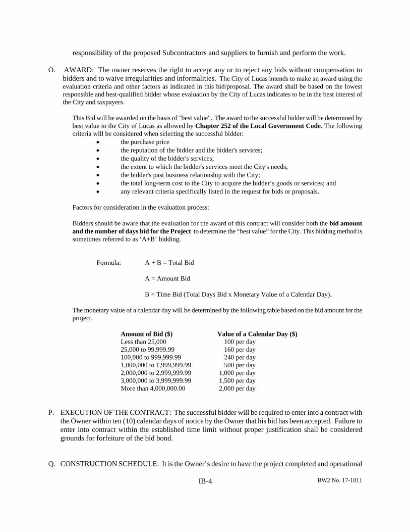
O. AWARD: The owner reserves the right to accept any or to reject any bids without compensation to bidders and to waive irregularities and informalities. The City of Lucas intends to make an award using the evaluation criteria and other factors as indicated in this bid/proposal. The award shall be based on the lowest responsible and best-qualified bidder whose evaluation by the City of Lucas indicates to be in the best interest of the City and taxpayers.
This Bid will be awarded on the basis of "best value". The award to the successful bidder will be determined by best value to the City of Lucas as allowed by Chapter 252 of the Local Government Code. The following criteria will be considered when selecting the successful bidder:
the purchase price the reputation of the bidder and the bidder's services; the quality of the bidder's services; the extent to which the bidder's services meet the City's needs; the bidder's past business relationship with the City; the total long-term cost to the City to acquire the bidder’s goods or services; and any relevant criteria specifically listed in the request for bids or proposals.
Factors for consideration in the evaluation process:
Bidders should be aware that the evaluation for the award of this contract will consider both the bid amount and the number of days bid for the Project to determine the “best value” for the City. This bidding method is sometimes referred to as ‘A+B’ bidding.
Formula: A + B = Total Bid
A = Amount Bid
B = Time Bid (Total Days Bid x Monetary Value of a Calendar Day).
The monetary value of a calendar day will be determined by the following table based on the bid amount for the project.
Amount of Bid ($) Value of a Calendar Day ($) Less than 25,000 100 per day 25,000 to 99,999.99 160 per day 100,000 to 999,999.99 240 per day 1,000,000 to 1,999,999.99 500 per day 2,000,000 to 2,999,999.99 1,000 per day 3,000,000 to 3,999,999.99 1,500 per day More than 4,000,000.00 2,000 per day
P. EXECUTION OF THE CONTRACT: The successful bidder will be required to enter into a contract with the Owner within ten (10) calendar days of notice by the Owner that his bid has been accepted. Failure to enter into contract within the established time limit without proper justification shall be considered grounds for forfeiture of the bid bond.
Q. CONSTRUCTION SCHEDULE: It is the Owner’s desire to have the project completed and operational
BW2 No. 17-1811 IB-5
in as short a time as possible. The number of calendar days for completion of the project will begin with the date specified in the Notice to Proceed. The Notice to Proceed will be issued in a manner to facilitate a smooth construction of the project. The Contractor shall begin construction within ten (10) calendar days of the issuance of the Notice to Proceed. The work shall be substantially complete within three hundred sixty (360) calendar days and finally complete within three hundred ninety (390) calendar days from the specified date of beginning.
R. LIQUIDATED DAMAGES: The time of completion for substantial completion is the essence of this
contract. For each calendar day that any work shall remain uncompleted after the time specified in the proposal and the contract, or the increased time granted by the Owner, as equitably increased by additional work or materials ordered after the contract is signed, the sum per day given in the following schedule shall be deducted from the monies due the Contractor:
$500 per Calendar Day
The sum of money thus deducted for such delay, failure or non-completion is not to be considered as a penalty, but shall be deemed, taken and treated as reasonable liquidated damages, per calendar day that the Contractor shall be in default after the time stipulated in the contract for substantially completing the work. The said amounts are fixed and agreed upon by and between the Owner and Contractor because of the impracticability and extreme difficulty of fixing and ascertaining the actual damages the Owner in such event would sustain and which shall be retained from the monies due, or that may become due, the Contractor under this contract; and if said monies be insufficient to cover the amount owing, then the Contractor or his surety shall immediately pay any additional amounts due. If the Contractor finds it impossible, for reasons beyond his control, to complete the work within the contract time as specified, the Contractor may make a written request for an extension of time in accordance with the General Provisions.
S. FORM OF CONTRACT: The contract for the construction of the project will be drawn up by the Owner.
A sample form of agreement is included in the Contract Agreement Section. T. BONDS: A Performance Bond, a Labor and Material Payment Bond and a Maintenance Bond will be
required by the Owner. Sample forms have been included in the Performance Bond, Payment Bond and Maintenance Bond sections.
U. BID SECURITY: Bids shall be accompanied by a cashier’s check or certified check upon a national or
state bank in an amount not less than five percent (5%) of the total maximum bid price payable without recourse to the City of Lucas, or a bid bond in the same amount from a reliable surety company as a guarantee that the bidder will enter into a contract and execute Performance Bond within ten (10) calendar days after notice or award of contract to him. Such checks or bid bonds will be returned to all except the three lowest bidders within three (3) days after the opening of bids upon demand of the bidder, and the remaining checks or bid bonds will be returned after the Owner has made an award of contract, or if no award has been made within sixty (60) calendar days after the date of the opening of bids, upon demand of the bidder at any time thereafter, so long as he has not been notified of the acceptance of this bid.
V. RESOLUTIONS: If the bidder is a corporation, a copy of the resolution empowering the person
submitting the bid to bind the bidder must be included with the bid.

BW2 No. 17-1811 IB-6
W. CONSTRUCTION STAKING: Construction staking will not be provided by the Owner. X. FINAL PAYMENT: The general provisions for Final Payment shall be as stated in Item 1.51.4 of the
North Central Texas Standard Specifications for Public Works Construction (current edition) including all Amendments and Additions. Prior to final payment, the Contractor shall provide the Owner with the following items:
1. A Contractor’s Affidavit of Bills Paid in accordance with Section BP.
2. A Consent of Surety Company to Final Payment.
3. A complete set of as-built plans which indicate all construction variations from the original
construction documents in accordance with the Special Provisions.
4. A two (2) year Maintenance Bond in accordance with Section MB. Y. WORKERS COMPENSATION: The Contractor shall meet all the conditions regarding Workers’
Compensation Insurance Coverage as set forth in the Special Provisions.
END OF SECTION

PF-1 BW2 No. 17-1811
SECTION PF
PROPOSAL FORM
BW2 No. 17-1811
BID FORM
, 2019
TO: The Honorable Mayor and City Council City of Lucas, Texas
RE: City of Lucas
Water System Improvements Single Pressure Plane Facilities North Pump Station
Gentlemen: The undersigned bidder, having examined the plans, specifications and contract documents, and the location of the proposed work, and being fully advised as to the extent and character of the work proposes to furnish all equipment and to perform labor and work necessary for completion of the work described by and in accordance with the Plans, Specifications and Contract for the following prices, to wit:
Signed by : ACKNOWLEDGMENT OF ADDENDA: The Bidder acknowledges receipt of the following addenda: Addendum No. 1. Addendum No. 2. Addendum No. 3. The work shall be substantially complete within three hundred sixty (360) calendar days and finally complete within three hundred ninety (390) calendar days. PF-2
CITY OF LUCASWATER SYSTEM IMPROVEMENTS
SINGLE PRESSURE PLANE FACILITIESNORTH PUMP STATION
BASE BID SCHEDULE
Item No.
Estimated Bid Quantity
Unit Description & Unit Price in Words Unit Price in Figures
Total Amount
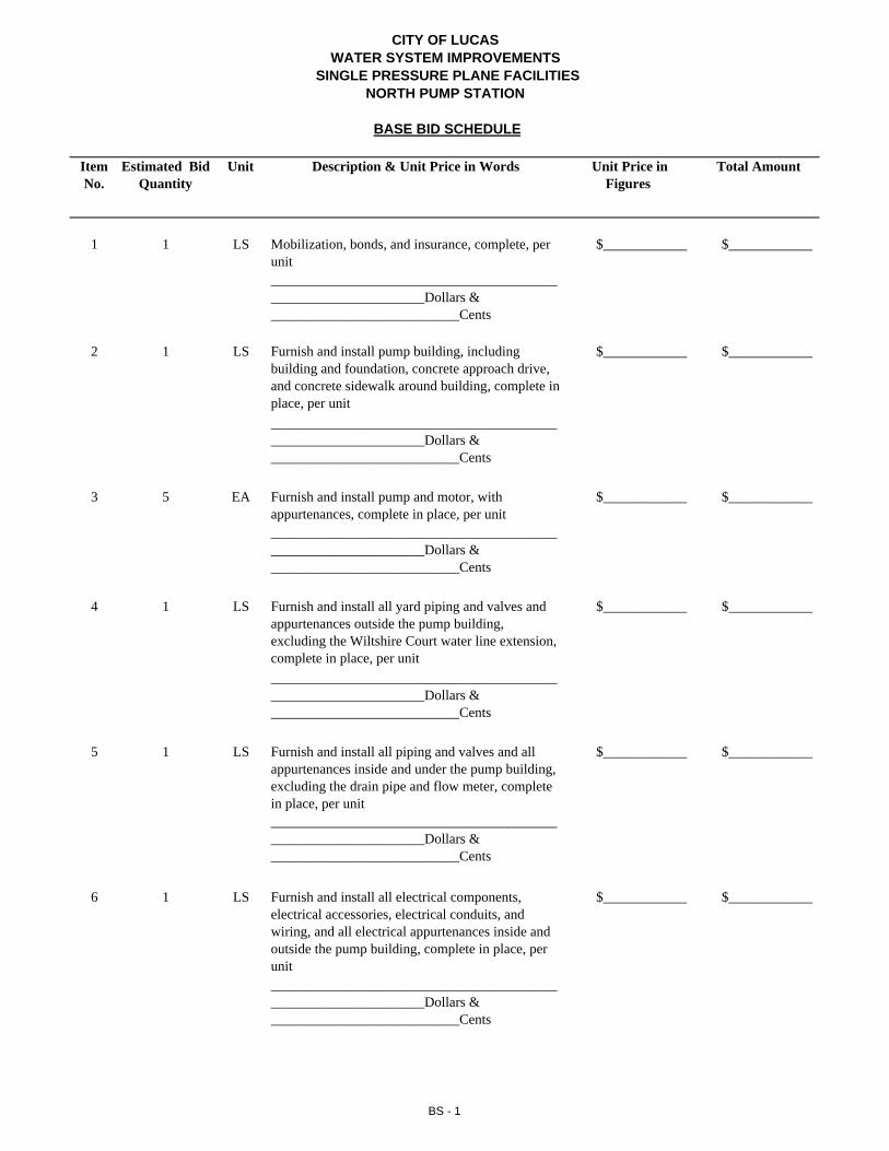
1 1 LS Mobilization, bonds, and insurance, complete, per unit
$____________ $____________
_______________________________________________________________Dollars & ___________________________Cents
2 1 LS Furnish and install pump building, including building and foundation, concrete approach drive, and concrete sidewalk around building, complete in place, per unit
$____________ $____________
_______________________________________________________________Dollars & ___________________________Cents
3 5 EA Furnish and install pump and motor, with appurtenances, complete in place, per unit
$____________ $____________
_______________________________________________________________Dollars & ___________________________Cents
4 1 LS Furnish and install all yard piping and valves and appurtenances outside the pump building, excluding the Wiltshire Court water line extension, complete in place, per unit
$____________ $____________
_______________________________________________________________Dollars & ___________________________Cents
5 1 LS Furnish and install all piping and valves and all appurtenances inside and under the pump building, excluding the drain pipe and flow meter, complete in place, per unit
$____________ $____________
_______________________________________________________________Dollars & ___________________________Cents
6 1 LS Furnish and install all electrical components, electrical accessories, electrical conduits, and wiring, and all electrical appurtenances inside and outside the pump building, complete in place, per unit
$____________ $____________
_______________________________________________________________Dollars & ___________________________Cents
BS - 1

CITY OF LUCASWATER SYSTEM IMPROVEMENTS
SINGLE PRESSURE PLANE FACILITIESNORTH PUMP STATION
BASE BID SCHEDULE
Item No.
Estimated Bid Quantity
Unit Description & Unit Price in Words Unit Price in Figures
Total Amount
7 1 LS Furnish and install all site work, complete in place, per unit
$____________ $____________
_______________________________________________________________Dollars & ___________________________Cents
8 1 LS Furnish and install temporary erosion control, including operational control of SW3P, complete in place, per unit
$____________ $____________
_______________________________________________________________Dollars & ___________________________Cents
9 5,000 SY Furnish and install hydromulch, complete in place, per unit
$____________ $____________
_______________________________________________________________Dollars & ___________________________Cents
10 5 EA Furnish and install pump control valve, complete in place, per unit
$____________ $____________
_______________________________________________________________Dollars & ___________________________Cents
11 1 LS Furnish and install piers that are shown on the structural drawings for the pump building, complete in place, per unit
$____________ $____________
_______________________________________________________________Dollars & ___________________________Cents
12 1 LS Furnish and install select fill required for pump station building, complete in place, per unit
$____________ $____________
_______________________________________________________________Dollars & ___________________________Cents
13 1 LS Furnish and install asphalt approach and flex base parking area, complete in place, per unit
$____________ $____________
_______________________________________________________________Dollars & ___________________________Cents
BS - 2
CITY OF LUCASWATER SYSTEM IMPROVEMENTS
SINGLE PRESSURE PLANE FACILITIESNORTH PUMP STATION
BASE BID SCHEDULE
Item No.
Estimated Bid Quantity
Unit Description & Unit Price in Words Unit Price in Figures
Total Amount
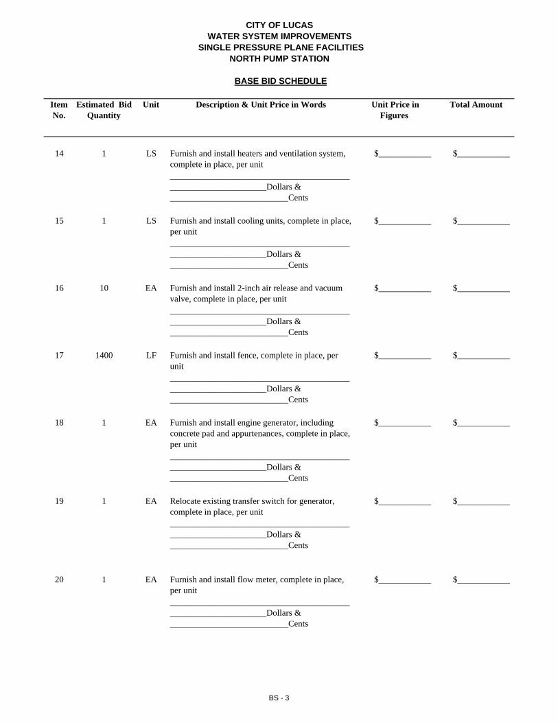
14 1 LS Furnish and install heaters and ventilation system, complete in place, per unit
$____________ $____________
_______________________________________________________________Dollars & ___________________________Cents
15 1 LS Furnish and install cooling units, complete in place, per unit
$____________ $____________
_______________________________________________________________Dollars & ___________________________Cents
16 10 EA Furnish and install 2-inch air release and vacuum valve, complete in place, per unit
$____________ $____________
_______________________________________________________________Dollars & ___________________________Cents
17 1400 LF Furnish and install fence, complete in place, per unit
$____________ $____________
_______________________________________________________________Dollars & ___________________________Cents
18 1 EA Furnish and install engine generator, including concrete pad and appurtenances, complete in place, per unit
$____________ $____________
_______________________________________________________________Dollars & ___________________________Cents
19 1 EA Relocate existing transfer switch for generator, complete in place, per unit
$____________ $____________
_______________________________________________________________Dollars & ___________________________Cents
20 1 EA Furnish and install flow meter, complete in place, per unit
$____________ $____________
_______________________________________________________________Dollars & ___________________________Cents
BS - 3
CITY OF LUCASWATER SYSTEM IMPROVEMENTS
SINGLE PRESSURE PLANE FACILITIESNORTH PUMP STATION
BASE BID SCHEDULE
Item No.
Estimated Bid Quantity
Unit Description & Unit Price in Words Unit Price in Figures
Total Amount
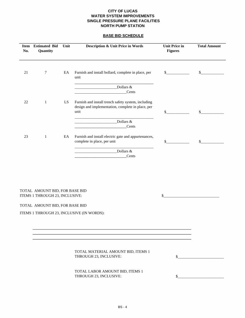
21 7 EA Furnish and install bollard, complete in place, per unit
$____________ $____________
_______________________________________________________________Dollars & ___________________________Cents
22 1 LS Furnish and install trench safety system, including design and implementation, complete in place, per unit $____________ $___________________________________________________________________________Dollars & ___________________________Cents
23 1 EA Furnish and install electric gate and appurtenances, complete in place, per unit $____________ $___________________________________________________________________________Dollars & ___________________________Cents
TOTAL MATERIAL AMOUNT BID, ITEMS 1 THROUGH 23, INCLUSIVE: $________________________
TOTAL LABOR AMOUNT BID, ITEMS 1 THROUGH 23, INCLUSIVE: $________________________
ITEMS 1 THROUGH 23, INCLUSIVE (IN WORDS):
TOTAL AMOUNT BID, FOR BASE BIDITEMS 1 THROUGH 23, INCLUSIVE: $_____________________________
TOTAL AMOUNT BID, FOR BASE BID
BS - 4

CITY OF LUCASWATER SYSTEM IMPROVEMENTS
SINGLE PRESSURE PLANE FACILITIESNORTH PUMP STATION
BASE BID SCHEDULE
Item No.
Estimated Bid Quantity
Unit Description & Unit Price in Words Unit Price in Figures
Total Amount
21 7 EA Furnish and install bollard, complete in place, per unit
$____________ $____________
_______________________________________________________________Dollars & ___________________________Cents
22 1 LS Furnish and install trench safety system, including design and implementation, complete in place, per unit $____________ $___________________________________________________________________________Dollars & ___________________________Cents
23 1 EA Furnish and install electric gate and appurtenances, complete in place, per unit $____________ $___________________________________________________________________________Dollars & ___________________________Cents
TOTAL MATERIAL AMOUNT BID, ITEMS 1 THROUGH 23, INCLUSIVE: $________________________
TOTAL LABOR AMOUNT BID, ITEMS 1 THROUGH 23, INCLUSIVE: $________________________
ITEMS 1 THROUGH 23, INCLUSIVE (IN WORDS):
TOTAL AMOUNT BID, FOR BASE BIDITEMS 1 THROUGH 23, INCLUSIVE: $_____________________________
TOTAL AMOUNT BID, FOR BASE BID
BS - 4
CITY OF LUCASWATER SYSTEM IMPROVEMENTS
SINGLE PRESSURE PLANE FACILITIES
ADD ALTERNATE BID NO. 1
Item No.
Estimated Bid Quantity
Unit Description & Unit Price in Words Unit Price in Figures
Total Amount
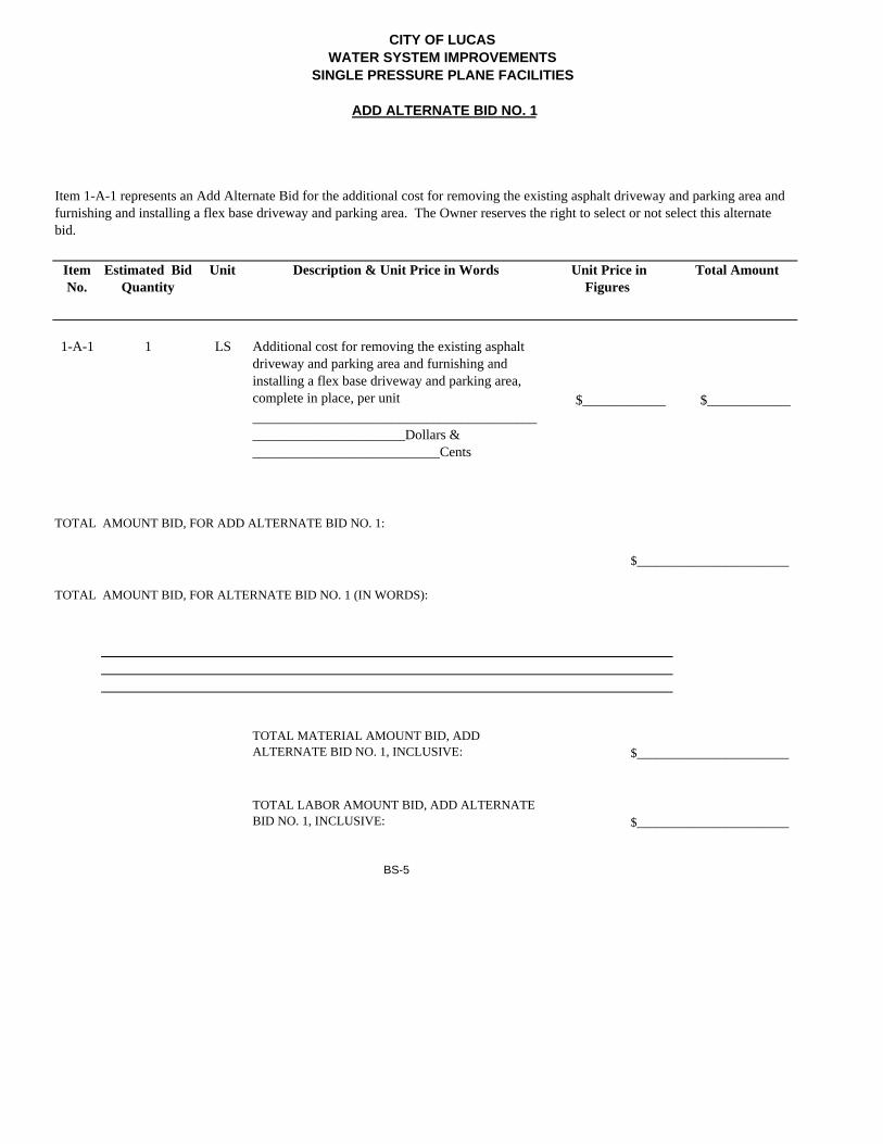
1-A-1 1 LS Additional cost for removing the existing asphalt driveway and parking area and furnishing and installing a flex base driveway and parking area, complete in place, per unit $____________ $___________________________________________________________________________Dollars & ___________________________Cents
$________________________
TOTAL MATERIAL AMOUNT BID, ADD ALTERNATE BID NO. 1, INCLUSIVE: $________________________
TOTAL LABOR AMOUNT BID, ADD ALTERNATE BID NO. 1, INCLUSIVE: $________________________
BS-5
TOTAL AMOUNT BID, FOR ADD ALTERNATE BID NO. 1:
Item 1-A-1 represents an Add Alternate Bid for the additional cost for removing the existing asphalt driveway and parking area and furnishing and installing a flex base driveway and parking area. The Owner reserves the right to select or not select this alternate bid.
TOTAL AMOUNT BID, FOR ALTERNATE BID NO. 1 (IN WORDS):
CITY OF LUCASWATER SYSTEM IMPROVEMENTS
SINGLE PRESSURE PLANE FACILITIES
ADD ALTERNATE BID NO. 2
Item No.
Estimated Bid Quantity
Unit Description & Unit Price in Words Unit Price in Figures
Total Amount
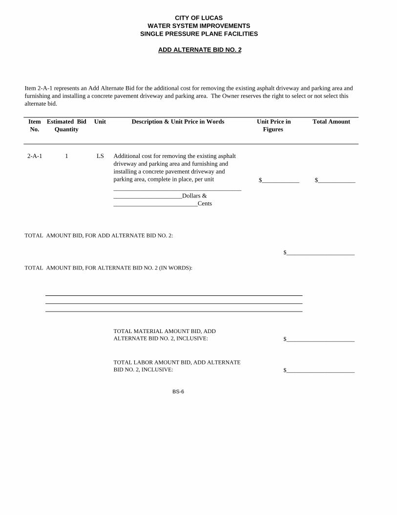
2-A-1 1 LS Additional cost for removing the existing asphalt driveway and parking area and furnishing and installing a concrete pavement driveway and parking area, complete in place, per unit $____________ $___________________________________________________________________________Dollars & ___________________________Cents
$________________________
TOTAL MATERIAL AMOUNT BID, ADD ALTERNATE BID NO. 2, INCLUSIVE: $________________________
TOTAL LABOR AMOUNT BID, ADD ALTERNATE BID NO. 2, INCLUSIVE: $________________________
BS-6
Item 2-A-1 represents an Add Alternate Bid for the additional cost for removing the existing asphalt driveway and parking area and furnishing and installing a concrete pavement driveway and parking area. The Owner reserves the right to select or not select this alternate bid.
TOTAL AMOUNT BID, FOR ADD ALTERNATE BID NO. 2:
TOTAL AMOUNT BID, FOR ALTERNATE BID NO. 2 (IN WORDS):

CITY OF LUCASWATER SYSTEM IMPROVEMENTS
SINGLE PRESSURE PLANE FACILITIES
ADD ALTERNATE BID NO. 3
Item No.
Estimated Bid Quantity
Unit Description & Unit Price in Words Unit Price in Figures
Total Amount
3-A-1 1 LS Additional cost for concrete blocks and a concrete pad for storage bins, complete in place, per unit
$____________ $___________________________________________________________________________Dollars & ___________________________Cents
$________________________
TOTAL MATERIAL AMOUNT BID, ADD ALTERNATE BID NO. 3, INCLUSIVE: $________________________
TOTAL LABOR AMOUNT BID, ADD ALTERNATE BID NO. 3, INCLUSIVE: $________________________
BS-7
Item 3-A-1 represents an Add Alternate Bid for the additional cost for concrete blocks and a concrete pad for storage bins. The Owner reserves the right to select or not select this alternate bid.
TOTAL AMOUNT BID, FOR ADD ALTERNATE BID NO. 3:
TOTAL AMOUNT BID, FOR ALTERNATE BID NO. 3 (IN WORDS):

CITY OF LUCASWATER SYSTEM IMPROVEMENTS
SINGLE PRESSURE PLANE FACILITIES
ADD ALTERNATE BID NO. 4
Item No.
Estimated Bid Quantity
Unit Description & Unit Price in Words Unit Price in Figures
Total Amount
4-A-1 870 LF Furnish and install Wiltshire Court 8" water line extension and associated valves, including 520 feet of open cut and 350 feet of boring and jacking w/14" steel casing, complete in place, per unit.
$____________ $___________________________________________________________________________Dollars & ___________________________Cents
$________________________
TOTAL MATERIAL AMOUNT BID, ADD ALTERNATE BID NO. 4, INCLUSIVE: $________________________
TOTAL LABOR AMOUNT BID, ADD ALTERNATE BID NO. 4, INCLUSIVE: $________________________
BS-8
Item 4-A-1 represents an Add Alternate Bid for the additional cost to furnish and install the Wiltshire Court 8" water line extension and associated valves. The Owner reserves the right to select or not select this alternate bid.
TOTAL AMOUNT BID, FOR ADD ALTERNATE BID NO. 4:
TOTAL AMOUNT BID, FOR ALTERNATE BID NO. 4 (IN WORDS):

CITY OF LUCASWATER SYSTEM IMPROVEMENTS
SINGLE PRESSURE PLANE FACILITIES
ADD ALTERNATE BID NO. 5
Item No.
Estimated Bid Quantity
Unit Description & Unit Price in Words Unit Price in Figures
Total Amount
5-A-1 1 LS Furnish and install restroom plumbing system and fixutures, electric water heater and hot water system, and toilet exhaust system, complete in place, per unit. $____________ $___________________________________________________________________________Dollars & ___________________________Cents
$________________________
TOTAL MATERIAL AMOUNT BID, ADD ALTERNATE BID NO. 5, INCLUSIVE: $________________________
TOTAL LABOR AMOUNT BID, ADD ALTERNATE BID NO. 5, INCLUSIVE: $________________________
BS-9
Item 5-A-1 represents an Add Alternate Bid for the additional cost to furnish and install a restroom and all appurtenances. The Owner reserves the right to select or not select this alternate bid.
TOTAL AMOUNT BID, FOR ADD ALTERNATE BID NO. 5:
TOTAL AMOUNT BID, FOR ALTERNATE BID NO. 5 (IN WORDS):
CITY OF LUCASWATER SYSTEM IMPROVEMENTS
SINGLE PRESSURE PLANE FACILITIES
ADD ALTERNATE BID NO. 6
Item No.
Estimated Bid Quantity
Unit Description & Unit Price in Words Unit Price in Figures
Total Amount
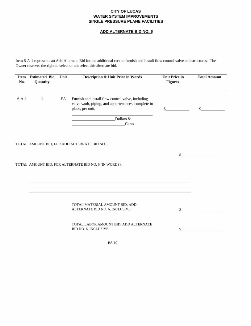
6-A-1 1 EA Furnish and install flow control valve, including valve vault, piping, and appurtenances, complete in place, per unit. $____________ $___________________________________________________________________________Dollars & ___________________________Cents
$________________________
TOTAL MATERIAL AMOUNT BID, ADD ALTERNATE BID NO. 6, INCLUSIVE: $________________________
TOTAL LABOR AMOUNT BID, ADD ALTERNATE BID NO. 6, INCLUSIVE: $________________________
BS-10
Item 6-A-1 represents an Add Alternate Bid for the additional cost to furnish and install flow control valve and structures. The Owner reserves the right to select or not select this alternate bid.
TOTAL AMOUNT BID, FOR ADD ALTERNATE BID NO. 6:
TOTAL AMOUNT BID, FOR ALTERNATE BID NO. 6 (IN WORDS):
CITY OF LUCASWATER SYSTEM IMPROVEMENTS
SINGLE PRESSURE PLANE FACILITIES
ADD ALTERNATE BID NO. 7
Item No.
Estimated Bid Quantity
Unit Description & Unit Price in Words Unit Price in Figures
Total Amount
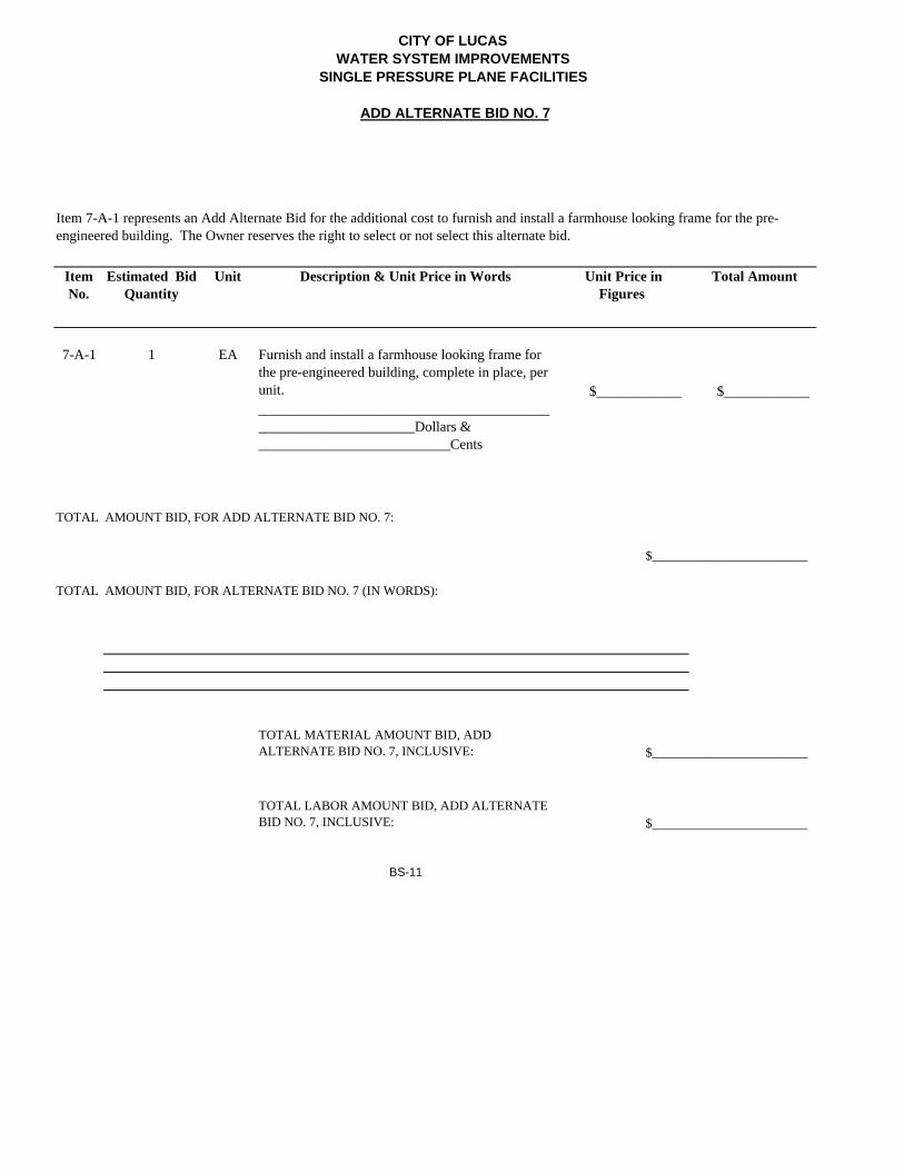
7-A-1 1 EA Furnish and install a farmhouse looking frame for the pre-engineered building, complete in place, per unit. $____________ $___________________________________________________________________________Dollars & ___________________________Cents
$________________________
TOTAL MATERIAL AMOUNT BID, ADD ALTERNATE BID NO. 7, INCLUSIVE: $________________________
TOTAL LABOR AMOUNT BID, ADD ALTERNATE BID NO. 7, INCLUSIVE: $________________________
BS-11
Item 7-A-1 represents an Add Alternate Bid for the additional cost to furnish and install a farmhouse looking frame for the pre-engineered building. The Owner reserves the right to select or not select this alternate bid.
TOTAL AMOUNT BID, FOR ADD ALTERNATE BID NO. 7:
TOTAL AMOUNT BID, FOR ALTERNATE BID NO. 7 (IN WORDS):

Bid No. 019‐19, Single Pressure Plane Facilities, North Pump Station Project BW2 No. 17‐1811 Schedule of Values
BID ENDORSEMENT FOR BID #019-19, Single Pressure Plane Facilities, North Pump Station Project:
The Contractor hereby agrees to commence work within Ten (10) days after the date written notice to do so shall have been given to him, and to finally complete the same within calendar days after the date of the written notice to commence work subject to such extensions of time as are provided by the General and Special Conditions. The work proposed to be done shall be accepted when fully completed and finished in accordance with the plans and specifications.
In the event of the award of a contract to the undersigned, the undersigned will furnish a Performance Bond and Payment Bond for the full amount of the contract. The undersigned certifies that the bid prices contained in this proposal have been carefully checked and are submitted as correct and final.
NOTE: Unit and lump sum prices must be shown in words and figures for each item listed in the Schedule of Values and in the event of discrepancy the words shall control.
The undersigned, in submitting this bid proposal and their endorsement of same, represents that they are authorized to obligate their firm, that they have read this entire bid proposal package, is aware of the covenants contained herein and will abide by and adhere to the expressed requirements. Submittals will be considered as being responsive only if entire Bid Package plus any/all attachments is returned with all blanks completed. The price portion of the bid is not the only consideration in the award.
The total days bid for this project cannot exceed 390 calendar days.
A – Amount Bid: $
Total Days Bid:
B – Total Days Value: $
Contractor
By: (please print name)
Signature:
Title:
Seal and Authorization (If a Corporation) Address
City, County, State and Zip
Telephone Fax No.
E-Mail Address:

BW2 No. 17-1811
NOTES: 1. All items, labor, materials (including fittings and appurtenances required for pipeline installation), additional mobilizations, incidentals and work required for construction of the project are to be provided and installed by the Contractor as part of the project, and the cost of such shall be included by the Contractor in the price bid for construction of the project. All items shown in the Plans and included in the Specifications shall be furnished and installed on this project. The Contractor shall include the costs for all of these items in an appropriate Bid Item. There shall be no additional pay for any of these items.
2. Prices must be shown in words and figures for each item listed in this proposal. In the
event of a discrepancy, the words shall control.
3. Materials, which are “tax exempt,” are those items which are physically incorporated into the facilities constructed for the OWNER, as set forth in the Special Provisions. Materials include, but are not limited to purchased items such as concrete, pumps, motors, electrical components, pipe, embedment, valves, etc.
4. Services, which are “not tax exempt,” are those items which are used by the
Contractor but are not physically incorporated into the OWNER’s facility and/or items which are consumed by construction, as set forth in the Special Provisions. Services include, but are not limited to, items such as supplies, tools, skill and labor, the purchase, rental or lease of equipment, etc.
5. Contractor shall provide OWNER with a breakdown of materials and services upon
request by OWNER.
6. Contractor shall provide trench safety during construction when and where it is required as a result of OSHA requirements, job conditions, site conditions, and/or soil conditions. All of the work required for trench safety shall be included in the Bid Item for the Trench Safety System.
7. Contractor shall be responsible for preparing and providing a Storm Water Pollution
Prevention Plan (SWPPP) if his construction procedures and activities are conducted in such a manner that more than one acre of land is disturbed on the project. Any costs for the SWPPP shall be included in the price bid for the erosion control item.
8. Contractor shall furnish and install a tracer wire that is compatible with and will allow detection by Radiodetection Corporation’s digital PXL-2 pipe locator or other locator, as determined by the City. The tracer wire shall be installed just above the proposed pipelines and throughout the length of the pipelines. The cost of the tracer wire shall be included in the cost of the pipe.
9. The total amount bid for mobilization, bonds and insurance shall not exceed 5% of the
total amount bid for the base bid.
10. The materials required for the Wiltshire Court 8” water line extension and associated valves and appurtenances shall not be acquired by the Contractor until the City approves the acquisition of such materials.
PF-3
BW2 No. 17-1811
11. With reference to the prevailing wage rates mentioned in Article 7.14 of the City’s standard contract form included in the Project Manual, this contract shall be based upon payment by the Contractor of wage rates not less than the general prevailing wage rates for work of similar character in this location. Also, the Contractor shall comply with the requirements of the current prevailing wage law of the State of Texas and the requirements of the Davis-Bacon Act, as applicable.
12. Site visits to the project site may be arranged by contacting Jeremy Bogle at the City
of Lucas (phone number 972-912-1210).
PF-4

BW2 No. 17-1811
BIDDER is: An Individual By (Seal)
(Individual’s Name) doing business as Business address: Phone No. A Partnership By (Seal)
(Firm Name)
(General Partner) doing business as Business address: Phone No. PF-5
BW2 No. 17-1811
A Corporation By
(Corporation Name)
(State of Incorporation)
By
(Name of Person Authorized to Sign)
(Title)
(Corporate Seal) Attest
(Secretary) Business address: Phone No. A Joint Venture By
(Name)
(Address)
By
(Name)
(Address)
(Each joint venturer must sign. The manner of signing for each individual, partnership and corporation that is a party to the joint venture should be in the manner indicated above.)
END OF SECTION
PF-6

CITY OF LUCAS, TEXAS
PUBLIC WORKS CONSTRUCTION PROJECT
SINGLE PRESSURE PLANE FACILITIES
NORTH PUMP STATION PROJECT
Bid No. 019-19
Contractor ____________________________________

i
TABLE OF CONTENTS ARTICLE I; THE CONTRACT AND THE CONTRACT DOCUMENTS 1 1.1 The Contract 1 1.2. The Contract Documents 1 1.3 Entire Agreement 1 1.4 No Privity with Others 1 1.5 Intent and Interpretation 1 1.6 Ownership of Contract Documents 2 ARTICLE II; THE WORK 2 2.1 2 2.2 Work 2 ARTICLE III; CONTRACT TIME 3 3.1 Substantial Completion 3 3.2 Time 3 3.3 Time is of the Essence 3 3.4 Liquidated Damages; Early Completion Bonus 4 3.5 No Damages for Delay; No Back-Charges; Damage Waiver 4 ARTICLE IV; CONTRACT PRICE 5 4.1 The Contract Price 5 ARTICLE V; PAYMENT OF THE CONTRACT PRICE 5 5.1 Schedule of Values 5 5.2 Payment Procedure 5 5.3 Withheld Payment 6 5.4 Unexcused Failure to Pay 6 5.5 Certificate of Substantial Completion 7 5.6 Completion and Final Payment 7 ARTICLE VI; THE CITY 8 6.1 Information, Services and Things Required from City 8 6.2 Right to Stop Work 8 6.3 City's Right to Perform Work 8 ARTICLE VII; THE CONTRACTOR 8 7.1 Must Follow Contract 8 7.2 Use of Web-Based Project Management System 8 7.3 Prosecution of Work 8 7.4 Warranty 9 7.5 Permits; Fees; Licenses 9 7.6 Supervision 9 7.7 Work Schedule 9 7.8 On-Site Drawings 10 7.9 As-Built Plans, Shop Drawings, Product Data, and Samples 10 7.10 Cleaning the Site and the Project 10 7.11 Access to Work and Inspections 10 7.12 Indemnity and Disclaimer 10 7.13 Nondiscrimination 11 7.14 Prevailing Wage Rates 11 7.15 Job Site Safety Precautions 11 7.16 Warning Devices and Barricades 12 7.17 Protection of Utilities and Other Contractors 12
ii
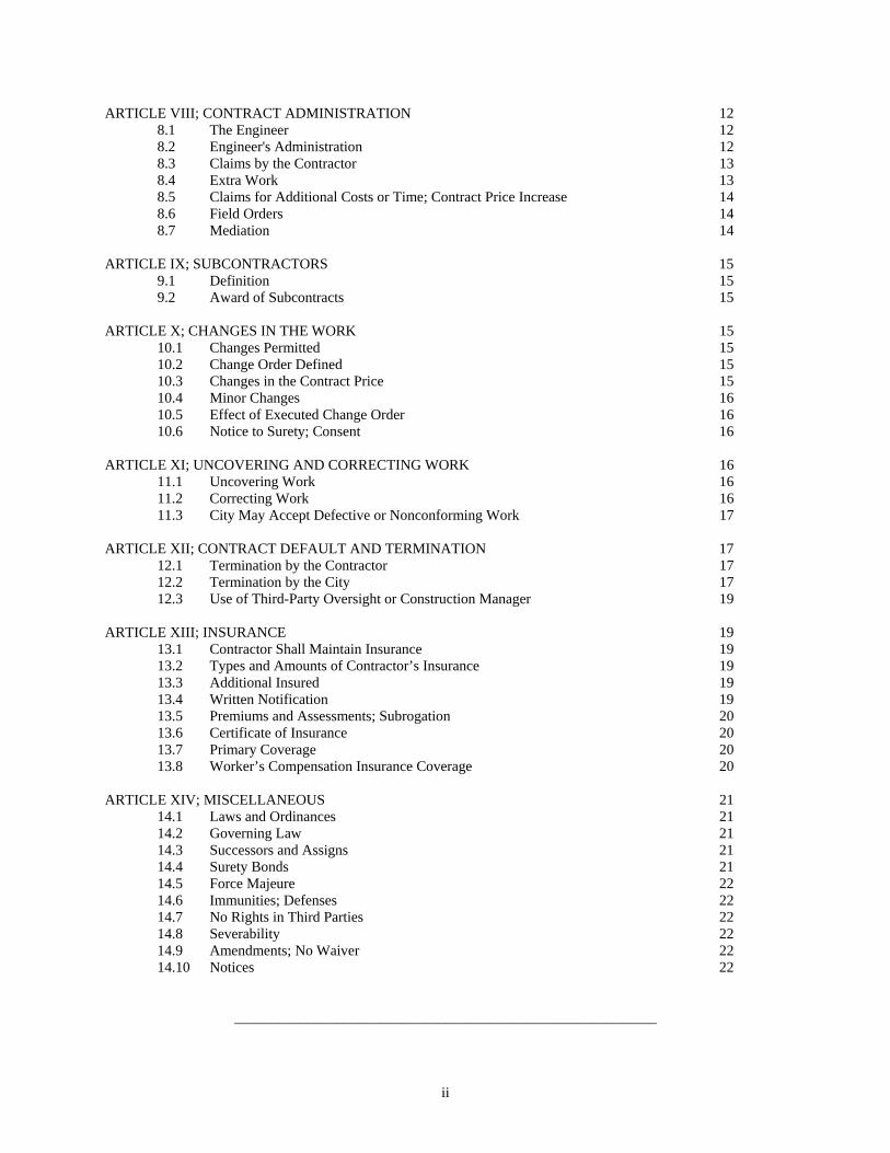
ARTICLE VIII; CONTRACT ADMINISTRATION 12 8.1 The Engineer 12 8.2 Engineer's Administration 12 8.3 Claims by the Contractor 13 8.4 Extra Work 13 8.5 Claims for Additional Costs or Time; Contract Price Increase 14 8.6 Field Orders 14 8.7 Mediation 14 ARTICLE IX; SUBCONTRACTORS 15 9.1 Definition 15 9.2 Award of Subcontracts 15 ARTICLE X; CHANGES IN THE WORK 15 10.1 Changes Permitted 15 10.2 Change Order Defined 15 10.3 Changes in the Contract Price 15 10.4 Minor Changes 16 10.5 Effect of Executed Change Order 16 10.6 Notice to Surety; Consent 16 ARTICLE XI; UNCOVERING AND CORRECTING WORK 16 11.1 Uncovering Work 16 11.2 Correcting Work 16 11.3 City May Accept Defective or Nonconforming Work 17 ARTICLE XII; CONTRACT DEFAULT AND TERMINATION 17 12.1 Termination by the Contractor 17 12.2 Termination by the City 17 12.3 Use of Third-Party Oversight or Construction Manager 19 ARTICLE XIII; INSURANCE 19 13.1 Contractor Shall Maintain Insurance 19 13.2 Types and Amounts of Contractor’s Insurance 19 13.3 Additional Insured 19 13.4 Written Notification 19 13.5 Premiums and Assessments; Subrogation 20 13.6 Certificate of Insurance 20 13.7 Primary Coverage 20 13.8 Worker’s Compensation Insurance Coverage 20 ARTICLE XIV; MISCELLANEOUS 21 14.1 Laws and Ordinances 21 14.2 Governing Law 21 14.3 Successors and Assigns 21 14.4 Surety Bonds 21 14.5 Force Majeure 22 14.6 Immunities; Defenses 22 14.7 No Rights in Third Parties 22 14.8 Severability 22 14.9 Amendments; No Waiver 22 14.10 Notices 22
__________________________________________________________
1
City of Lucas, Texas
This Agreement is made by and between the City of Lucas, Texas, a home-rule municipality (hereinafter referred to as the "City") and Contractor ______________________________, (hereinafter referred to as the "Contractor") for construction of Single Pressure Plane Facilities North Pump Station Projet, (hereinafter referred to as the "Project"), the City and the Contractor hereby agreeing as follows:
ARTICLE I
THE CONTRACT AND THE CONTRACT DOCUMENTS
1.1 THE CONTRACT
1.1.1 The contract between the City and the Contractor, of which this agreement (sometimes referred to herein as the “Contract”) is a part, consists of the Contract Documents. It shall be effective on the date this Agreement is executed by the last party to execute it.
1.2. THE CONTRACT DOCUMENTS
1.2.1 The Contract Documents consist of this agreement, the General Conditions, the Special Conditions, the Invitation to Bid, Requirements and Instructions to Bidders, the Specifications, the Drawings, the Shop Drawings, the Project Manual, all Change Orders and Field Orders issued hereafter, the addenda, exhibits and attachments thereto, any other amendments hereto executed by the parties hereafter, together with the following (if any):
1.3 ENTIRE AGREEMENT
1.3.1 This Contract, together with the Contractor's performance and payment bonds for the Project, all General Conditions, Special Conditions, Plans and Specifications, and Addenda attached thereto, constitute the entire and exclusive agreement between the City and the Contractor with reference to the Project. Specifically, but without limitation, this Contract supersedes any bid documents and all prior written or oral communications, representations and negotiations, if any, between the City and Contractor not expressly made a part hereof.
1.4 NO PRIVITY WITH OTHERS
1.4.1 Nothing contained in this Contract shall create, or be interpreted to create, privity or any other contractual agreement between the City and any person or entity other than the Contractor.
1.5 INTENT AND INTERPRETATION
1.5.1 The intent of this Contract is to require complete, correct and timely execution of the Work. Any Work that may be required, implied or inferred by the Contract Documents, or any one or more of them, as necessary to produce the intended result shall be provided by the Contractor for the Contract Price.
1.5.2 This Contract is intended to be an integral whole and shall be interpreted as internally consistent. What is required by any one Contract Document shall be considered as required by the Contract.
1.5.3 When a word, term or phrase is used in this Contract, it shall be interpreted or construed, first, as defined herein; second, if not defined, according to its generally accepted meaning in the construction industry; and third, if there is no generally accepted meaning in the construction industry, according to its common and customary usage.

2
1.5.4 The word “City” includes the City of Lucas, Texas, a municipal corporation, and its public officials, officers, employees, agents and employees. The word “Contractor” includes the Contractor and its officers, employees, agents and representatives. The word "include", "includes", or "including", as used in this subparagraph and in this Contract, shall be deemed to be followed by the phrase, "without limitation".
1.5.5 The specification herein of any act, failure, refusal, omission, event, occurrence or condition as constituting a material breach of this Contract shall not imply that any other, non-specified act, failure, refusal, omission, event, occurrence or condition shall be deemed not to constitute a material breach of this Contract.
1.5.6 Words or terms used as nouns in this Contract shall be inclusive of their singular and plural forms, unless the context of their usage clearly requires a contrary meaning. 1.5.7 The Contractor shall have a continuing duty to read, carefully study and compare each of the Contract Documents, the Shop Drawings, the Product Data, and any Plans and Specifications, and shall give written notice to the City of any inconsistency, ambiguity, error or omission which the Contractor may discover with respect to these documents before proceeding with the affected Work. The issuance, or the express or implied approval by the City or the Engineer of the Contract Documents, Shop Drawings or Product Data, shall not relieve the Contractor of the continuing duties imposed hereby, nor shall any such approval be evidence of the Contractor's compliance with this Contract. The City has requested the Engineer to only prepare documents for the Project, including the Drawings, Plans and Specifications for the Project, which are accurate, adequate, consistent, coordinated and sufficient for construction. HOWEVER, THE CITY MAKES NO REPRESENTATION OR WARRANTY OF ANY NATURE WHATSOEVER TO THE CONTRACTOR CONCERNING SUCH DOCUMENTS. THE CONTRACTOR ASSUMES ALL RISK OF ERRORS, AMBIGUITIES AND INACCURACIES. By the execution hereof, the Contractor acknowledges and represents that it has received, reviewed and carefully examined such documents, has found them to be complete, accurate, adequate, consistent, coordinated and sufficient for construction, and that the Contractor has not, does not, and will not rely upon any representation or warranties by the City concerning such documents as no such representation or warranties have been or are hereby made. Further, the Contractor represents and warrants that it has had a sufficient opportunity to inspect the Project site and assumes any and all responsibility for inadequacies or ambiguities in the plans, drawings or specifications as well as for latent conditions of the site where the work is to be performed.
1.5.8 As between numbers and scaled measurements on the Drawings and in the Design, the numbers shall govern, as between larger scale and smaller scale drawings, the larger scale shall govern.
1.5.9 Neither the organization of any of the Contract Documents into divisions, sections, paragraphs, articles, (or other categories), nor the organization or arrangement of the Design, shall control the Contractor in dividing the Work or in establishing the extent or scope of the Work to be performed by Subcontractors. 1.6 OWNERSHIP OF CONTRACT DOCUMENTS
1.6.1 The Contract Documents, and each of them individually and collectively, shall remain the property of the City. The Contractor shall have the right to keep one record set of the Contract Documents upon completion of the Project; provided, however, that in no event shall Contractor use, or permit to be used, any or all of such Contract Documents on other projects without the City's prior written authorization.
ARTICLE II
THE WORK
2.1 The Contractor shall perform all of the Work required, implied or reasonably inferable from this Contract.
3
2.2 WORK
2.2.1 The term "Work" shall mean whatever is done by or required of the Contractor to perform and complete its duties under this Contract, including the following: construction of the whole or a designated part of the Project; furnishing of any required surety bonds and insurance, and the provision or furnishing of labor, supervision, services, materials, supplies, equipment, fixtures, appliances, facilities, tools, transportation, storage, permits and licenses required of the Contractor, power, water, fuel, heat, light, cooling and all other utilities as required by this Contract. The Work to be performed by the Contractor is generally described as follows: Constructing a new pump station, yard piping, pump station piping, flow control valve and structure, site work, and miscellaneous related appurtenances as per plans and specifications.
2.2.2 The Contractor shall be responsible for paying for and procuring all materials and labor and furnishing all services necessary or appropriate for the full performance of the Work and the for the full completion of the Project. All materials shall be new and materials and workmanship shall be of good quality. Upon request, the Contractor shall furnish satisfactory proof of the type, kind, and quality of materials.
ARTICLE III
CONTRACT TIME
3.1 SUBSTANTIAL COMPLETION
3.1.1 "Substantial Completion" shall mean that stage in the progression of the Work when the Work is sufficiently complete in accordance with this Contract that the City can enjoy beneficial use or occupancy of the Work and can utilize the Work for its intended purpose, even though minor miscellaneous work and/or adjustment may be required.
3.2 TIME
3.2.1 The Contractor shall commence the Work within 10 days of receipt of a written Notice to Proceed, and shall achieve Substantial Completion of the Work no later than Three Hundred Sixty (360) calendar days from the date specified in the Notice to Proceed. The term “calendar days” shall mean any and all days of the week or month, no days being excepted. The number of calendar days from the date on which the Work is permitted to proceed, through the date set forth for Substantial Completion, shall constitute the Contract Time” and the “scheduled completion date.” The execution of this Contract by the Contractor constitutes an agreement that adequate time has been allotted for this Contract, given the Contract Price.
3.2.2 Work may proceed on any day of the week, including weekends, and at any time of the day. However, work shall not occur on such days or at such times as, in the City’s or Engineer’s discretion, may be a violation of noise or environmental regulations or ordinances, or when the presence of workers, equipment or materials may create an abnormally hazardous condition.
3.2.3 The Contractor shall submit and comply with construction schedules establishing completion timelines and deadlines for each component of the Project. Construction schedules shall be submitted to and approved by the Engineer and the City on a regular basis as required by the Contract Documents. If no reference is made to construction schedules in the Contract Documents, then construction schedules shall be submitted with each Application for Payment.

4
3.3 TIME IS OF THE ESSENCE
3.3.1 The scheduled completion date is based on public necessity. The scheduled completion date is factored into and is a material component of the Contract Price. All limitations of time set forth in the Contract Documents are of the essence of this Contract.
3.3.2 TIME IS OF THE ESSENCE IN THE PERFORMANCE OF THE WORK AND THE COMPLETION OF THE PROJECT ON OR BEFORE THE SCHEDULED COMPLETION DATE. THE SCHEDULED COMPLETION DATE IS A DEADLINE. THE CITY EMPLOYS A ZERO-TOLERANCE POLICY REGARDING THE TIME FOR COMPLETION. The time for completion is an essential and material term of this Contract and the Contractor’s failure to achieve substantial completion on the date stated herein, to comply with work schedules, or achieve milestones in approved construction schedules, shall be a material breach and default of this Contract.
3.3.3 The City will assess liquidated damages for late or untimely performance and may, at the City’s sole option, elect to allow Contractor to continue with the Work, or may declare Contractor to be in breach and default of the Contract and order Contractor to remove all equipment and personnel from the work site. All remedies for Contractor’s late performance shall be nonexclusive and cumulative without waiver of any other, and the City’s election of one shall not preclude the City from pursuing any other.
3.3.4 It is contemplated by the parties that the progress of the Work may be delayed by certain conditions beyond the control of the parties; these delays have been contemplated by the parties and considered in the time allotted for performance specified herein and in the contract price and includes, but is not limited to delays occasioned on account of adverse weather, temporary unavailability of materials, shipment delays, and the presence and potential interference of other contractors or of utilities that may be performing work at the Project site unrelated to this Contract. These delays have been considered and included in the determination of the scheduled completion date and the Contract Price. 3.4 LIQUIDATED DAMAGES; EARLY COMPLETION BONUS
3.4.1 The Contractor shall pay the City the sum of $500.00 per day for each and every calendar day of unexcused delay in achieving Substantial Completion beyond the date set forth herein for Substantial Completion of the Work. Any sums due and payable hereunder by the Contractor shall be payable, not as a penalty, but as liquidated damages representing an estimate of delay damages likely to be sustained by the City, estimated at or before the time of executing this Contract. When the City reasonably believes that Substantial Completion will be inexcusably delayed, the City shall be entitled, but not required, to withhold from any amounts otherwise due the Contractor an amount then believed by the City to be adequate to recover liquidated damages applicable to such delays. If and when the Contractor overcomes the delay in achieving Substantial Completion, or any part thereof, for which the City has withheld payment, the City shall promptly release to the Contractor those funds withheld, but no longer applicable, as liquidated damages. If the Contractor has submitted a Statement of Delay with the appropriate Application for Payment as required by Subparagraph 5.2.3, and/or has complied with the notice and Change Order requirements of this Contract, the Engineer shall have sole discretion to determine whether a delay is excused or unexcused and the Engineer’s determination thereof shall be final and binding on the parties.
3.4.2 In the event that the Contractor achieves certification by the Engineer of Final Completion prior to __________ [ENTER DATE FOR EARLY COMPLETION BONUS] Calendar days from the date specified in the Notice to Proceed, the City shall pay to the Contractor the sum of $____________ [ENTER DAILY AMOUNT OF INCENTIVE] per day for each calendar day that Final Completion is certified in advance of the scheduled Final Completion date, as that date may be modified by written change order. However, early completion bonuses shall not, in the aggregate, exceed the total sum of $______________ [ENTER MAXIMUM AMOUNT OF EARLY COMPLETION BONUS]. Any reduction in the scope of work, evidenced by written change order, shall commensurately reduce the Contract Time. 3.5 NO DAMAGES FOR DELAY; NO BACK-CHARGES; DAMAGE WAIVER

5
3.5.1 No claim shall be made by the Contractor to the City, and no damages, costs or extra compensation shall be allowed or paid by the City to the Contractor for any delay or hindrance from any cause in the progress or completion of the Work or this Contract. The Contractor’s sole remedy in the event of any delay or hindrance, regardless of cause, shall be to request time extensions by written change orders as provided for hereinafter. The failure to seek or obtain a change order for time extension shall be deemed a waiver thereof and Contractor shall be regarded as having made a determination that the delay will not affect the completion of the Work. Should the Contractor be delayed by an act of the City, or should the City order a stoppage of the Work for sufficient cause unrelated to any act or omission of the Contractor, an extension of time shall be granted by the City by Change Order upon written application, which extension shall not be unreasonably denied, to compensate for the delay.
3.5.2 The City shall have the authority to suspend the Work wholly or in part for such period or periods of time as it may deem appropriate due to unsuitable conditions considered unfavorable for the proper prosecution of the Work or for the failure of the Contractor to carry out instructions from the City or City’s representative. During any period in which the Work is stopped or during which any of the Work is not actively in progress for any reason, Contractor shall properly protect the site and the Work from damage, loss or harm. The Contractor shall not be compensated for periods of delay caused by a suspension of the work by the City. If work is suspended due to unsuitable conditions through no fault of the Contractor, an extension of time shall be granted by the City by Change Order upon written application, which extension shall not be unreasonably denied, to compensate for the delay.
3.5.3 The Contractor shall not have or assert any claim against the City for damages or back-charges of any kind for any reason, including but not limited to claims for Extra Work, damages, economic loss, additional costs, unknown latent site conditions, and refusals by the City to grant extensions of time, unless supported and authorized by a written Change Order or separate agreement signed by all parties. The Contractor, in entering into this Contract, hereby waives, releases, quitclaims, discharges and holds harmless the City from and against any and all claims, damages, liabilities and losses, save and except those arising under Paragraph 12.1 of this Contract.
ARTICLE IV
CONTRACT PRICE
4.1 THE CONTRACT PRICE
4.1.1 The City shall pay, and the Contractor shall accept, as full and complete payment for all of the Work required herein, the fixed sum of
$ ______________________________________________
The sum set forth in this Paragraph 4.1 shall constitute the Contract Price which shall not be modified except by written Change Order as provided in this Contract, or the assessment of liquidated damages or the award of an early completion bonus.
ARTICLE V
PAYMENT OF THE CONTRACT PRICE
5.1 SCHEDULE OF VALUES
5.1.1 The Schedule of Values, submitted to and accepted by the City and Engineer at the time of the Contractor’s bid, allocates the Contract Price to the various portions of the Work. The Contractor's Schedule of Values shall hav e been prepared, or at the City’s or Engineer’s request shall be amended prior to the commencement of construction, in such form, with such detail, and supported by such data as the Engineer or the City may require to substantiate its accuracy. The Contractor shall not imbalance its Schedule of Values nor artificially inflate any element thereof. The violation of this provision by the Contractor shall constitute a material breach of this Contract.

6
The Schedule of Values shall be used only as a basis for the Contractor's Applications for Payment and shall only constitute such basis after it has been acknowledged and accepted in writing by the Engineer and the City.
5.2 PAYMENT PROCEDURE
5.2.1 The City shall pay the Contract Price to the Contractor as provided below.
5.2.2 PROGRESS PAYMENTS - Based upon the Contractor's Applications for Payment submitted to the Engineer and upon Certificates for Payment subsequently issued to the City by the Engineer, the City shall make progress payments to the Contractor on account of the Contract Price. 5.2.3 APPLICATION FOR PAYMENT - On or before the 25th day of each month after commencement of the Work, the Contractor shall submit an Application for Payment for the period ending the 15th day of the month to the Engineer in such form and manner, and with such supporting data and content, as the City or the Engineer may require. The Contractor may request payment for that portion of the Contract Price properly allocable to Contract requirements properly provided and to labor, materials and equipment properly incorporated in the Work, less retainage and less the total amount of previous payments received from the City. Such Application for Payment shall be signed by the Contractor and shall constitute the Contractor's representation that the Work has progressed to the level for which payment is requested in accordance with the Schedule of Values, that the Work has been properly installed or performed in full compliance with this Contract, and that the Contractor knows of no reason why payment should not be made as requested. Thereafter, the Engineer will review the Application for Payment and may also review the Work at the Project site or elsewhere to determine whether the quantity and quality of the Work is as represented in the Application for Payment and is as required by this Contract. The Engineer shall determine and certify to the City the amount properly owing to the Contractor. The City shall make partial payments on account of the Contract Price to the Contractor within thirty (30) days following the Engineer's receipt and approval of each Application for Payment. The amount of each partial payment shall be the amount certified for payment by the Engineer less such amounts, if any, otherwise owing by the Contractor to the City or which the City shall have the right to withhold as authorized by this Contract. The Engineer's certification of the Contractor's Application for Payment shall not preclude the City from the exercise of any of its rights as set forth in Paragraph 5.3 hereinbelow. 5.2.4 STATEMENT OF DELAY - Each Application for Payment shall include a Statement of Delay showing the number of days lost due to inclement weather, conflicts with other City contractors, utilities, or design specifications, or other proper reasons. The failure to submit the Statement of Delay shall be a waiver of any claim for additional days or extensions of the scheduled completion date. 5.2.5 RETAINAGE - If the Contract Price set forth in Subparagraph 4.1.1 exceeds $400,000, the City shall withhold retainage of ten (10) percent from each progress payment to secure performance of the Contract and shall deposit in an interest-bearing account that portion of the retainage withheld that exceeds five (5) percent of the progress payment. If a different percentage is set forth in the Invitation to Bid, then that percentage shall apply.
5.2.6 The Contractor warrants that title to all Work covered by an Application for Payment will pass to the City when installed at the Project site, regardless of the time of payment. The Contractor further warrants that upon submittal of an Application for Payment, all Work for which payments have been received from the City shall be free and clear of liens, claims, security interest or other encumbrances in favor of the Contractor or any other person or entity whatsoever.
5.2.7 The Contractor shall promptly pay each Subcontractor out of the amount paid to the Contractor on account of such Subcontractor's Work, the amount to which such Subcontractor is entitled. In the event the City becomes informed that the Contractor has not paid a Subcontractor as herein provided, the City shall have the right, but not the duty, to issue future checks in payment to the Contractor of amounts otherwise due hereunder naming the Contractor and such Subcontractor as joint payees. Such joint check procedure, if employed by the City, shall create no rights in favor of any person or entity beyond the right of the named payees to payment of the check and shall not be deemed to commit the City to repeat the procedure in the future.
5.2.8 No progress payment, nor any use or occupancy of the Project by the City, shall be interpreted to constitute an acceptance of any Work not in strict compliance with this Contract.
7
5.3 WITHHELD PAYMENT
5.3.1 The City may decline to make payment, may withhold funds, and, if necessary, may demand the return of some or all of the amounts previously paid to the Contractor, to protect the City from loss because of:
(a) defective Work not remedied by the Contractor or, in the opinion of the City, likely to be remedied by the Contractor;
(b) claims of third parties against the City or the City's property;
(c) failure by the Contractor to pay Subcontractors or others in a prompt and proper fashion;
(d) evidence that the balance of the Work cannot be completed in accordance with the Contract for the unpaid balance of the Contract Price,
(e) evidence that the Work will not be completed in the time required for substantial or final completion (final completion meaning the full and final completion of all work called for by this Contract and final acceptance by the Engineer and the City);
(f) persistent failure to carry out the Work in accordance with the Contract;
(g) damage to the City or a third party to whom the City is, or may be, liable.
(h) failure to submit an updated project schedule in accordance with Subparagraph 3.2.3.
(i) failure to submit record drawings in accordance with Subparagraph 7.9.1.
In the event that the City makes written demand upon the Contractor for amounts previously paid by the City as contemplated in this Subparagraph 5.3.1, the Contractor shall promptly comply with such demand. The City shall have no duty to third parties to withhold payment to the Contractor and shall incur no liability for a failure to withhold funds.
5.4 UNEXCUSED FAILURE TO PAY
5.4.1 If within twenty (20) days after the date established herein for payment to the Contractor by the City, the City, without cause or basis hereunder, fails to pay the Contractor any amount then due and payable to the Contractor, then the Contractor may after ten (10) additional days' written notice to the City and the Engineer, and without prejudice to any other available rights or remedies it may have, stop the Work until payment of those amounts due from the City have been received. Late payments shall not accrue interest or other late charges.
5.5 CERTIFICATE OF SUBSTANTIAL COMPLETION
5.5.1 When the Contractor believes that the Work is substantially complete, the Contractor shall submit to the Engineer a list of items to be completed or corrected. When the Engineer and the City on the basis of an inspection determine that the Work is in fact substantially complete, the Engineer will prepare a Certificate of Substantial Completion which shall establish the date of Substantial Completion, shall state the responsibilities of the City and the Contractor for Project security, maintenance, heat, utilities, damage to the Work, and insurance, and shall fix the time within which the Contractor shall complete the items listed therein. In no event, however, shall the date of Final Completion be delayed. Guarantees required by the Contract shall commence on the date of Substantial Completion of the Work; however, the maintenance bond required herein, and the assurances given thereunder, shall commence of and from the date of final acceptance of the work by the City. The Certificate of Substantial Completion shall be submitted to the City and the Contractor for their written acceptance of the responsibilities assigned to them in such certificate.

8
Upon Substantial Completion of the Work, and execution by both the City and the Contractor of the Certificate of Substantial Completion, the City shall pay the Contractor for all work completed to date, less retainage.
5.6 COMPLETION AND FINAL PAYMENT
5.6.1 When all of the Work is finally complete and the Contractor is ready for a final inspection, it shall notify the City and the Engineer thereof in writing. Thereupon, the Engineer will make final inspection of the Work and, if the Work is complete in full accordance with this Contract and this Contract has been fully performed, the Engineer will promptly issue a final Certificate for Payment certifying to the City that the Project is complete and the Contractor is entitled to the remainder of the unpaid Contract Price (including retainage and the interest accrued on the retainage in excess of five (5) percent if the Contract Price is in excess of $400,000), plus an early completion bonus, if any, less any amount withheld pursuant to this Contract. If the Engineer is unable to issue its final Certificate for Payment and is required to repeat its final inspection of the Work, the Contractor shall bear the cost of such repeat final inspection(s) which cost may be deducted by the City from the Contractor's final payment.
5.6.1.1 If the Contractor fails to achieve final completion within the time fixed therefor by the Engineer in its Certificate of Substantial Completion, the Contractor shall pay the City the sum set forth hereinabove as liquidated damages per day for each and every calendar day of unexcused delay in achieving final completion beyond the date set forth herein for final completion of the Work. Any sums due and payable hereunder by the Contractor shall be payable, not as a penalty, but as liquidated damages representing an estimate of delay damages likely to be sustained by the City, estimated at or before the time of executing this Contract. When the City reasonably believes that final completion will be inexcusably delayed, the City shall be entitled, but not required, to withhold from any amounts otherwise due the Contractor an amount then believed by the City to be adequate to recover liquidated damages applicable to such delays. If and when the Contractor overcomes the delay in achieving final completion, or any part thereof, for which the City has withheld payment, the City shall promptly release to the Contractor those funds withheld, but no longer applicable, as liquidated damages. Liquidated damages shall be deducted first from any earned early completion bonus, then from any sums otherwise due to the Contractor.
5.6.2 The Contractor shall not be entitled to final payment unless and until it submits to the Engineer its affidavit that all payrolls, invoices for materials and equipment, and other liabilities connected with the Work for which the City, or the City's property might be responsible, have been fully paid or otherwise satisfied; releases and waivers of lien from all Subcontractors of the Contractor and of any and all other parties required by the Engineer or the City; consent of Surety, if any, to final payment. If any third party fails or refuses to provide a release of claim or waiver of lien as required by the City, the Contractor shall furnish a bond satisfactory to the City to discharge any such lien or indemnify the City from liability.
5.6.3 The City shall make final payment of all sums due the Contractor within thirty (30) days of the Engineer's execution of a final Certificate for Payment.
5.6.4 Acceptance of final payment shall constitute a waiver of all claims against the City by the Contractor except for those claims previously made in writing against the City by the Contractor, pending at the time of final payment, and identified in writing by the Contractor as unsettled at the time of its request for final payment.
5.6.5 Other than interest on retainage in excess of 5% under Paragraph 5.2.5, under no circumstances shall Contractor be entitled to receive interest on any payments or monies due Contractor by the City, whether the amount on which the interest may accrue is timely, late, wrongfully withheld, or an assessment of damages of any kind.
ARTICLE VI
THE CITY 6.1 INFORMATION, SERVICES AND THINGS REQUIRED FROM CITY

9
6.1.1 The City shall furnish to the Contractor, at the time of executing this Contract, any and all written and tangible material in its possession concerning conditions below ground at the site of the Project. Such written and tangible material is furnished to the Contractor only in order to make complete disclosure of such material and for no other purpose. By furnishing such material, the City does not represent, warrant, or guarantee its accuracy either in whole, in part, implicitly or explicitly, or at all, and shall have no liability therefor. The City shall also furnish surveys, legal limitations and utility locations (if known), and a legal description of the Project site.
6.1.2 Excluding permits and fees normally the responsibility of the Contractor, the City shall obtain all approvals, easements, and the like required for construction and shall pay for necessary assessments and charges required for construction, use or occupancy of permanent structures or for permanent changes in existing facilities.
6.1.3 The City shall furnish the Contractor, free of charge, two copies of the Contract Documents for execution of the Work.
6.2 RIGHT TO STOP WORK
6.2.1 If the Contractor persistently fails or refuses to perform the Work in accordance with this Contract, if the Contractor fails to meet milestones set forth in approved construction schedules, if the City has sufficient reason to believe that the Contractor is not and will not complete the Project by the scheduled completion date, or if the best interests of the public health, safety or welfare so require, the City may order the Contractor to stop the Work, or any described portion thereof, until the cause for stoppage has been corrected, no longer exists, or the City orders that Work be resumed. In such event, the Contractor shall immediately obey such order.
6.3 CITY'S RIGHT TO PERFORM WORK
6.3.1 If the Contractor's Work is stopped by the City under Paragraph 6.2, and the Contractor fails within seven (7) days of such stoppage to provide adequate assurance to the City that the cause of such stoppage will be eliminated or corrected, then the City may, without prejudice to any other rights or remedies the City may have against the Contractor, proceed to carry out the subject Work. In such a situation, an appropriate Change Order shall be issued deducting from the Contract Price the cost of correcting the subject deficiencies, plus compensation for the Engineer's additional services and expenses necessitated thereby, if any. If the unpaid portion of the Contract Price is insufficient to cover the amount due the City, the Contractor shall pay the difference to the City.
ARTICLE VII
THE CONTRACTOR
7.1 MUST FOLLOW CONTRACT
7.1.1 The Contractor shall perform no part of the Work at any time without adequate Contract Documents or, as appropriate, approved Shop Drawings, Product Data or Samples for such portion of the Work. If the Contractor performs any of the Work knowing it involves a recognized error, inconsistency or omission in the Contract Documents without such notice to the Engineer, the Contractor shall bear responsibility for such performance and shall bear the cost of correction. The Contractor shall perform the Work strictly in accordance with this Contract
7.2 PROSECUTION OF WORK
7.3.1 The Contractor shall supervise and direct the Work using the Contractor's best skill, effort and attention. The Contractor shall be responsible to the City for any and all acts or omissions of the Contractor, its employees and others engaged in the Work on behalf of the Contractor.

10
7.3.2 The Contractor shall give adequate attention to the faithful prosecution of the Work and the timely completion of this Contract, with authority to determine the manner and means of performing such Work, so long as such methods insure timely completion and proper performance.
7.3.3 The Contractor shall exercise all appropriate means and measures to insure a safe and secure jobsite in order to avoid and prevent injury, damage or loss to persons or property.
7.3.4 The City will not interfere with the Contractor’s manner and means of performing the Work. However, the City’s insistence on strict compliance with the Contract shall not be regarded as an interference with the Contractor’s manner and means. In the event that any part of the Work is not in strict compliance with the Contract, the Contractor is and shall be estopped from claiming any interference by the City or Engineer with the Contractor’s manner and means of performing that part of the Work.
7.4 WARRANTY
7.4.1 The Contractor warrants to the City that all labor furnished to progress the Work under this Contract will be competent to perform the tasks undertaken, that the product of such labor will yield only first-class results, that materials and equipment furnished will be of good quality and new unless otherwise permitted by this Contract, and that the Work will be of good quality, free from faults and defects and in strict conformance with this Contract. All Work not conforming to these requirements may be considered defective. THE CONTRACTOR WARRANTS AND GUARANTIES THAT IT SHALL COMPLETE THE WORK AND ACHIEVE SUBSTANTIAL COMPLETION BY THE SCHEDULED COMPLETION DATE, STRICTLY IN ACCORDANCE WITH THIS CONTRACT. DEFECTIVE WORK OR MATERIALS SHALL BE FIXED, REPAIRED OR REPLACED FREE OF CHARGE OR COST TO THE CITY.
7.5 PERMITS; FEES; LICENSES
The Contractor shall obtain and pay for all permits, fees and licenses necessary and ordinary for the Work. The Contractor shall comply with all lawful requirements applicable to the Work and shall give and maintain any and all notices required by applicable law pertaining to the Work.
7.6 SUPERVISION
7.6.1 The Contractor shall employ and maintain at the Project site only competent supervisory personnel. Absent written instruction from the Contractor to the contrary, the superintendent shall be deemed the Contractor's authorized representative at the site and shall be authorized to receive and accept any and all communications from the City or the Engineer.
7.6.2 Key supervisory personnel assigned by the Contractor to this Project are as follows:
NAME FUNCTION
____________________ ____________________
____________________ ____________________
____________________ ____________________
____________________ ____________________
____________________ ____________________
So long as the individuals named above remain actively employed or retained by the Contractor, they shall perform the functions indicated next to their names unless the City agrees to the contrary in writing. In the event one or more

11
individuals not listed above subsequently assume one or more of those functions listed above, the Contractor shall be bound by the provisions of this Subparagraph 7.6.2 as though such individuals had been listed above.
7.7 WORK SCHEDULE
7.7.1 At the pre-construction meeting, the Contractor shall submit to the City and the Engineer for their information, the Contractor's schedule for completing the Work (also referred to herein as the construction schedule). The Contractor's schedule shall be revised no less frequently than monthly (unless the parties otherwise agree in writing) and shall be revised to reflect conditions encountered from time to time and shall be related to the entire Project. Each such revision shall be furnished to the City and the Engineer.
7.7.2 The Contractor’s schedule for completing the Work and any revised schedules, shall demonstrate achievement of substantial completion by the scheduled completion date. Failure by the Contractor to strictly comply with the provisions of this Paragraph 7.7 shall constitute a default and a material breach of this Contract.
7.8 ON-SITE DRAWINGS
7.8.1 The Contractor shall continuously maintain at the site, for the benefit of the City and the Engineer, one record copy of this Contract marked to record on a current basis changes, selections and modifications made during construction. Additionally, the Contractor shall maintain at the site for the City and Engineer the approved Shop Drawings, Product Data, Samples and other similar required submittals. Upon final completion of the Work, all of these record documents shall be delivered to the City. 7.9 RECORD DRAWINGS/PLANS, AS-BUILT PLANS, SHOP DRAWINGS, PRODUCT DATA, AND SAMPLES
7.9.1 The Contractor shall submit, with each Application for Payment, As-Built plans for any and each part or portion of the Project that varies from the Engineer’s plans and specifications and the Contract Documents.
7.9.2 Shop Drawings, Product Data, Samples and other submittals from the Contractor do not constitute Contract Documents. Their purpose is merely to demonstrate the manner in which the Contractor intends to implement the Work in conformance with information received from the Contract Documents.
7.9.3 The Contractor shall not perform any portion of the Work requiring submittal and review of Shop Drawings, Product Data or Samples unless and until such submittal shall have been approved by the Engineer. Approval by the Engineer, however, shall not be evidence that Work installed pursuant thereto conforms to the requirements of this Contract. 7.10 CLEANING THE SITE AND THE PROJECT
7.10.1 The Contractor shall keep the site reasonably clean during performance of the Work. The Contractor shall clean the site and the Project and remove all waste, rubbish, temporary structures, and other materials during construction and, upon completion of construction, shall clean the site and remove all such material together with all of the Contractor's property therefrom. Contractor shall dispose of all refuse at a landfill approved by the Texas Commission on Environmental Quality. The Contractor shall further restore all property damaged during the prosecution of the Work and shall leave the site in a clean and presentable condition. No additional payment shall be made by the City for this work, the compensation having been considered and included in the contract price.
7.11 ACCESS TO WORK AND INSPECTIONS
7.11.1 The City and the Engineer shall have access to the Work at all times from commencement of the Work through final completion. The Contractor shall take whatever steps necessary to provide access when requested. When reasonably requested by the City or the Engineer, the Contractor shall perform or cause to be performed such testing as may be necessary or appropriate to insure suitability of the jobsite or the Work’s compliance with the Contract requirements.

12
7.12 INDEMNITY AND DISCLAIMER
7.12.1 CITY SHALL NOT BE LIABLE OR RESPONSIBLE FOR, AND SHALL BE INDEMNIFIED, DEFENDED, HELD HARMLESS AND RELEASED BY CONTRACTOR FROM AND AGAINST ANY AND ALL SUITS, ACTIONS, LOSSES, DAMAGES, CLAIMS, OR LIABILITY OF ANY CHARACTER, TYPE, OR DESCRIPTION, INCLUDING ALL EXPENSES OF LITIGATION, COURT COSTS, AND ATTORNEY'S FEES, FOR INJURY OR DEATH TO ANY PERSON, INJURY OR LOSS TO ANY PROPERTY, OR ECONOMIC LOSS, RECEIVED OR SUSTAINED BY ANY PERSON OR PERSONS, INCLUDING THE CONTRACTOR, OR PROPERTY, DIRECTLY OR INDIRECTLY ARISING OUT OF, OR OCCASIONED BY THE PERFORMANCE OF CONTRACTOR UNDER THIS CONTRACT, INCLUDING CLAIMS AND DAMAGES ARISING IN WHOLE OR IN PART FROM THE NEGLIGENCE OF CITY, WITHOUT WAIVING THE CITY’S GOVERNMENTAL, SOVEREIGN OR OTHER IMMUNITIES OR DEFENSES AVAILABLE TO THE CITY UNDER TEXAS LAW AND WITHOUT WAIVING ANY DEFENSES OF THE PARTIES UNDER TEXAS LAW. IT IS THE EXPRESS INTENT OF THE PARTIES TO THIS CONTRACT THAT THE INDEMNITY PROVIDED FOR HEREIN IS AN INDEMNITY EXTENDED BY CONTRACTOR TO INDEMNIFY AND PROTECT CITY FROM THE CONSEQUENCES OF THE CONTRACTOR’S AS WELL AS THE CITY'S NEGLIGENCE, WHETHER SUCH NEGLIGENCE IS THE SOLE OR PARTIAL CAUSE OF ANY SUCH INJURY, DEATH, OR DAMAGE.
The provisions of this indemnification are solely for the benefit of the parties hereto and not intended to create or grant any rights, contractual or otherwise, to any other person or entity.
7.12.2 The Contractor will secure and maintain contractual liability insurance to cover this indemnification agreement that will be primary and non-contributory as to any insurance maintained by the City for its own benefit, including self-insurance. In addition, Contractor shall obtain and file with City a standard form Certificate of Insurance evidencing the required coverage.
7.12.3 In claims against any person or entity indemnified under this Paragraph 7.12 by an employee of the Contractor, a Subcontractor, anyone directly or indirectly employed by them or anyone for whose acts they may be liable, the indemnification obligation under this Paragraph 7.12 shall not be limited by a limitation on amount or type of damages, compensation or benefits payable by or for the Contractor or a Subcontractor under workers' compensation acts, disability benefit acts or other employee benefit acts.
7.13 NONDISCRIMINATION
7.13.1 The Contractor shall not discriminate in any way against any person, employee or job applicant on the basis of race, color, creed, national original, religion, age, sex, or disability where reasonable accommodations can be effected to enable the person to perform the essential functions of the job. The Contractor shall further insure that the foregoing nondiscrimination requirement shall be made a part and requirement of each subcontract on this Project.
7.14 PREVAILING WAGE RATES
7.14.1 The Contractor shall comply in all respects with all requirements imposed by any laws, ordinances or resolutions applicable to the Project with regard to the minimum prevailing wage rates for all classes of employees, laborers, subcontractors, mechanics, workmen and persons furnishing labor and services to the Project. The City has adopted a Prevailing Wage Rate Schedule, available to the Contractor by request (or attached to this contract as a part of the exhibits), which specifies the classes and wage rates to be paid to all persons. The Contractor shall pay not less than the minimum wage rates established thereby for each class, craft or type of labor, workman, or
13
mechanic employed in the execution of this Contract. The failure of the Contractor to comply with this requirement shall result in the forfeiture to the City of a sum of not less than Sixty Dollars ($60.00) for each person per day, or portion thereof, that such person is paid less than the prevailing rate. Upon request by the City, Contractor shall make available for inspection and copying its books and records, including but not limited to its payroll records, account information and other documents as may be required by the City to insure compliance with this provision.
7.15 JOB SITE SAFETY PRECAUTIONS
7.15.1 The Contractor shall at all times exercise reasonable precautions for the safety of its employees, laborers, subcontractors, mechanics, workmen and others on and near the jobsite and shall comply with all laws, ordinances, regulations, and standards of federal, state and local safety laws and regulations. The Contractor shall provide such machinery guards, safe walk-ways, ladders, bridges, and other safety devices as may be necessary or appropriate to insure a safe and secure jobsite and shall require its subcontractors to comply with this requirement. The Contractor shall immediately comply with any and all safety requirements imposed by the Engineer during the progress of the Work.
7.16 WARNING DEVICES AND BARRICADES 7.16.1 The Contractor shall furnish and maintain such warning devices, barricades, lights, signs, pavement markings, and other devices as may be necessary or appropriate or required by the Engineer to protect persons or property in, near or adjacent to the jobsite. No separate compensation shall be paid to the Contractor for such measures. Where the Work is being conducted in, upon or near streets, alleys, sidewalks, or other rights-of-way, the Contractor shall insure the placement, maintenance and operation of any and all such warning devices as may be required by the City and shall do so until no longer required by the City. Such devices shall be in compliance with and conform to the manual and specifications for the uniform system of traffic control devices adopted by the Texas Department of Transportation. 7.17 PROTECTION OF UTILITIES AND OTHER CONTRACTORS
7.17.1 The Contractor shall use best efforts to leave undisturbed and uninterrupted all utilities and utility services provided to the jobsite or which presently exists at, above or beneath the location where the Work is to be performed. In the event that any utility or utility service is disturbed or damaged during the progress of the Work, the Contractor shall forthwith repair, remedy or restore the utility at Contractor’s sole expense. The Contractor shall coordinate any utility conflicts with the owner of the utility and no extension of time will be requested or given if adequate coordination is not provided by Contractor.
7.17.2 The Contractor understands and acknowledges that other contractors of the City or of other entities may be present at the jobsite performing other work unrelated to the Project. The Contractor shall use best efforts to work around other contractors without impeding the work of others while still adhering to the scheduled completion date. In the event that the Contractor’s work is or may be delayed by any other person, the Contractor shall immediately give notice thereof to the Engineer and shall request a written Change Order in accordance with the procedures set forth by this Contract. The Contractor’s failure to provide such notice and to request such Change Order shall constitute a waiver of any and all claims associated therewith.
ARTICLE VIII
CONTRACT ADMINISTRATION
8.1 THE ENGINEER
8.1.1 When used in this Contract the term “Engineer” does not necessarily denote a duly licensed, trained or certified engineer; as used herein, the term shall be used interchangeably and shall mean a designated Engineer, Engineer, or Contract Administrator (who may not be an architect or engineer) for the City, said person to be
14
designated or re-designated by the City prior to or at any time during the Work hereunder. The Engineer may be an employee of the City or may be retained by the City as an independent contractor but, in either event, the Engineer’s duties and authority shall be as set forth hereinafter. The Contractor understands and agrees that it shall abide by the decisions and instructions of the Engineer notwithstanding the contractual relationship between the City and Engineer, the title of Contract Administrator, or the fact that the Engineer is an employee of the City.
In the event the City should find it necessary or convenient to replace the Engineer, the City shall retain a replacement Engineer and the status of the replacement Engineer shall be that of the former Engineer.
8.2 ENGINEER'S ADMINISTRATION
8.2.1 The Engineer, unless otherwise directed by the City in writing, will perform those duties and discharge those responsibilities allocated to the Engineer as set forth in this Contract. The Engineer shall be the City's representative from the effective date of this Contract until final payment has been made.
8.2.2 The City and the Contractor shall communicate with each other in the first instance through the Engineer. 8.2.3 The Engineer shall be the initial interpreter of the requirements of the drawings and specifications and the judge of the performance thereunder by the Contractor. The Engineer shall render written or graphic interpretations necessary for the proper execution or progress of the Work with reasonable promptness on request of the Contractor.
8.2.4 The Engineer will review the Contractor's Applications for Payment and will certify to the City for payment to the Contractor, those amounts then due the Contractor as provided in this Contract.
8.2.5 The Engineer shall have authority to reject Work which is defective or does not conform to the requirements of this Contract. If the Engineer deems it necessary or advisable, the Engineer shall have authority to require additional inspection or testing of the Work for compliance with Contract requirements.
8.2.6 The Engineer will review and approve, or take other appropriate action as necessary, concerning the Contractor's submittals including Shop Drawings, Product Data and Samples. Such review, approval or other action shall be for the sole purpose of determining conformance with the design concept and information given through the Contract Documents.
8.2.7 The Engineer will prepare Change Orders and may authorize minor changes in the Work by Field Order as provided elsewhere herein.
8.2.8 The Engineer shall, upon written request from the Contractor, conduct inspections to determine the date of Substantial Completion and the date of final completion, will receive and forward to the City for the City's review and records, written warranties and related documents required by this Contract and will issue a final Certificate for Payment upon compliance with the requirements of this Contract.
8.2.9 The Engineer's decisions in matters relating to aesthetic effect shall be final if consistent with the intent of this Contract.
8.3 CLAIMS BY THE CONTRACTOR
8.3.1 The Engineer shall determine all claims and matters in dispute between the Contractor and City with regard to the execution, progress, or sufficiency of the Work or the interpretation of the Contract Documents, including but not limited to the plans and specifications. Any dispute shall be submitted in writing to the Engineer within seven (7) days of the event or occurrence or the first appearance of the condition giving rise to the claim or dispute and the Engineer shall render a written decision within a reasonable time thereafter. The Engineer’s decisions shall be final and binding on the parties. In the event that either party objects to the Engineer’s determination as to any submitted dispute, that party shall submit a written objection to the Engineer and the opposing party within ten (10) days of receipt of the Engineer’s written determination in order to preserve the objection. Failure to so object shall constitute a waiver of the objection for all purposes.

15
8.3.2 Pending final resolution of any claim of the Contractor, the Contractor shall diligently proceed with performance of this Contract and the City shall continue to make payments to the Contractor in accordance with this Contract.
8.3.3 CLAIMS FOR CONCEALED, LATENT OR UNKNOWN CONDITIONS - The Contractor expressly represents that it has been provided with an adequate opportunity to inspect the Project site and thoroughly review the Contract Documents and plans and specifications prior to submission of its bid and the City’s acceptance of the bid. Subject to the conditions hereof, Contractor assumes full responsibility and risk for any concealed, latent or unknown condition which may affect the Work. No claims for extra work or additional compensation shall be made by Contractor in connection with concealed, latent or unknown conditions except as expressly provided herein. Should concealed, latent or unknown conditions encountered in the performance of the Work (a) below the surface of the ground or (b) in an existing structure be at variance with the conditions indicated by this Contract, or should unknown conditions of an unusual nature differing materially from those ordinarily encountered in the area and generally recognized as inherent in Work of the character provided for in this Contract, be encountered, the Contract Price shall be equitably adjusted by Change Order upon the written notice and claim by either party made within seven (7) days after the first observance of the condition. As a condition precedent to the City having any liability to the Contractor for concealed or unknown conditions, the Contractor must give the City and the Engineer written notice of, and an opportunity to observe, the condition prior to disturbing it. The failure by the Contractor to make the written notice and claim as provided in this Subparagraph shall constitute a waiver by the Contractor of any claim arising out of or relating to such concealed, latent or unknown condition and the Contractor thereby assumes all risks and additional costs associated therewith.
8.4 EXTRA WORK
8.4.1 The Contractor shall not claim, request or demand any sum from the City for Extra Work or for additional costs, and hereby waives all such claims, requests and demands and any right to assert same, unless the conditions of this subparagraph are strictly complied with. “Extra Work” is defined herein to mean any labor, service, materials, equipment, supplies or charges that are directly or indirectly related to the Work, the Project or the Project site, that is not necessarily or fairly required or implied by the Contract Documents.
8.4.2 The parties acknowledge and agree that there shall be no payment made by the City to the Contractor without a written agreement (either a separate contract or a written Change Order) signed by the parties. Should the Contractor perform Extra Work or be requested to perform Extra Work by the Engineer or City, it shall be the Contractor’s obligation and duty to first apply for and obtain a written Change Order, approved by the Engineer and executed by the City. The Contractor’s failure to obtain a written, signed Change Order prior to commencement of Extra Work shall constitute a complete and final waiver of any right for compensation for the Extra Work.
8.5 CLAIMS FOR ADDITIONAL COSTS OR TIME; CONTRACT PRICE INCREASE
8.5.1 If the Contractor wishes to make a claim for an increase in the Contract Price, as a condition precedent to any liability of the City therefor, the Contractor shall give the Engineer written notice of such claim within seven (7) days after the occurrence of the event, or the first appearance of the condition, giving rise to such claim. Such notice shall be given by the Contractor before proceeding to execute any additional or changed Work. The failure by the Contractor to give such notice and to give such notice prior to executing the Work shall constitute a waiver of any right to or claim for additional compensation.
8.5.2 In connection with any claim by the Contractor against the City for compensation in excess of the Contract Price, any liability of the City for the Contractor's costs shall be strictly limited to direct costs incurred by the Contractor and shall in no event include indirect costs or consequential damages of the Contractor. The City shall not be liable to the Contractor for claims of third parties, including Subcontractors. The City shall not be liable to the Contractor for any claims based upon delay to the Contractor for any reason whatsoever including any act or neglect on the part of the City.
8.5.3 If the Contractor is delayed in progressing any task which at the time of the delay is then critical or which during the delay becomes critical, as the sole result of any act or neglect to act by the City or someone acting in the City's behalf, or by changes ordered in the Work, unusual delay in transportation, unusually adverse weather

16
conditions not reasonably anticipated, fire or any causes beyond the Contractor's control, then the date for achieving Substantial Completion of the Work shall be extended upon the written notice and claim of the Contractor to the City and the Engineer, for such reasonable time as the Engineer may determine. Any notice and claim for an extension of time by the Contractor shall be made not more than seven (7) days after the occurrence of the event or the first appearance of the condition giving rise to the claim and shall set forth in detail the Contractor's basis for requiring additional time in which to complete the Project. In the event the delay to the Contractor is a continuing one, only one notice and claim for additional time shall be necessary. If the Contractor fails to make such claim as required in this Subparagraph, any claim for an extension of time shall be waived. The procedures and remedies provided by this provision shall be the sole remedy of Contractor and Contractor shall not assert nor be entitled to any additional delays or damages associated therewith.
8.6 FIELD ORDERS
8.6.1 The Engineer shall have authority to order minor changes in the Work not involving a change in the Contract Price or in Contract Time and not inconsistent with the intent of the Contract. Such changes shall be effected by Field Order and shall be binding upon the Contractor. The Contractor shall carry out such Field Orders promptly.
8.7 MEDIATION
8.7.1 In the event that a dispute arises under the terms of this Contract, following an adverse determination by the Engineer and proper preservation of the issue as required herein, the parties agree to submit to mediation. In such event, the parties shall agree to a designated person to serve as mediator and each party shall be responsible for payment of one-half of the total mediation fees. The parties shall submit the dispute to mediation as soon as practical and in no event later than one (1) year after the Engineer’s written decision on the matter. At least one designated representative of each party must attend and participate in good faith in an effort to resolve the matters in dispute.
8.7.2 In no event shall the foregoing provision justify or authorize any delay in the progress of the Work; the parties shall abide by the decision of the Engineer in accomplishing the timely completion of the Project.
ARTICLE IX
SUBCONTRACTORS
9.1 DEFINITION
9.1.1 A Subcontractor is a person or entity that has a direct contract with the Contractor to perform a portion of the Work. No Subcontractor shall be in privity with the City.
9.2 AWARD OF SUBCONTRACTS
9.2.1 Upon execution of the Contract, the Contractor shall furnish the City, in writing, the names of persons or entities proposed by the Contractor to act as a Subcontractor on the Project. The City shall promptly reply to the Contractor, in writing, stating any objections the City may have to such proposed Subcontractor. The Contractor shall not enter into a subcontract with a proposed Subcontractor with reference to whom the City has made timely objection. The Contractor shall not be required to subcontract with any party to whom the Contractor has objection.
9.2.2 All subcontracts shall afford the Contractor rights against the Subcontractor which correspond to those rights afforded to the City against the Contractor herein, including those rights afforded to the City by Subparagraph 12.2.1 below. All subcontracts shall incorporate by reference the provisions hereof and shall provide that no claims, causes or demands shall be made by any Subcontractor against the City.
17
9.2.3 The Contractor shall indemnify, defend and hold harmless the City from and against any and all claims, demands, causes of action, damage, and liability asserted or made against the City by or on behalf of any Subcontractor.
ARTICLE X
CHANGES IN THE WORK
10.1 CHANGES PERMITTED
10.1.1 Changes in the Work within the general scope of this Contract, consisting of additions, deletions, revisions, or any combination thereof, may be ordered without invalidating this Contract, by Change Order or by Field Order.
10.1.2 Changes in the Work shall be performed under applicable provisions of this Contract and the Contractor shall proceed promptly with such changes.
10.2 CHANGE ORDER DEFINED
10.2.1 Change Order shall mean a written order to the Contractor executed by the City and the Engineer, issued after execution of this Contract, authorizing and directing a change in the Work or an adjustment in the Contract Price or the Contract Time, or any combination thereof. The Contract Price and the Contract Time may be changed only by written Change Order.
10.3 CHANGES IN THE CONTRACT PRICE
10.3.1 Any change in the Contract Price resulting from a Change Order shall be determined as follows: (a) by mutual agreement between the City and the Contractor as evidenced by (1) the change in the Contract Price being set forth in the Change Order, (2) such change in the Contract Price, together with any conditions or requirements related thereto, being initialed by both parties, and (3) the Contractor's execution of the Change Order, or (b) if no mutual agreement occurs between the City and the Contractor, then, as provided in Subparagraph 10.3.2 below.
10.3.2 If no mutual agreement occurs between the City and the Contractor as contemplated in Subparagraph 10.3.1 above, the change in the Contract Price, if any, shall then be determined by the Engineer on the basis of the reasonable expenditures or savings of those performing, deleting or revising the Work attributable to the change, including, in the case of an increase or decrease in the Contract Price, a reasonable allowance for direct job site overhead and profit. In such case, the Contractor shall present, in such form and with such content as the City or the Engineer require, an itemized accounting of such expenditures or savings, plus appropriate supporting data for inclusion in a Change Order. Reasonable expenditures or savings shall be limited to the following: reasonable costs of materials, supplies, or equipment including delivery costs, reasonable costs of labor, including social security, old age and unemployment insurance, fringe benefits required by agreement or custom, and workers' compensation insurance, reasonable rental costs of machinery and equipment exclusive of hand tools whether rented from the Contractor or others, reasonable costs of premiums for all bonds and insurance, permit fees, and sales, use or other taxes related to the Work, and reasonable cost of direct supervision and jobsite field office overhead directly attributable to the change. In no event shall any expenditure or savings associated with the Contractor's home office or other non-jobsite overhead expense be included in any change in the Contract Price. Pending final determination of reasonable expenditures or savings to the City, payments on account shall be made to the Contractor on the Engineer's Certificate for Payment.
10.3.3 If unit prices are provided in the Contract, and if the quantities contemplated are so changed in a proposed Change Order that application of such unit prices to the quantities of Work proposed will cause substantial inequity to the City or to the Contractor, the applicable unit prices shall be equitably adjusted.
18
10.4 MINOR CHANGES
10.4.1 The Engineer shall have authority to order minor changes in the Work not involving a change in the Contract Price or an extension of the Contract Time and not inconsistent with the intent of this Contract. Such minor changes shall be made by written Field Order, and shall be binding upon the City and the Contractor. The Contractor shall promptly carry out such written Field Orders.
10.5 EFFECT OF EXECUTED CHANGE ORDER
10.5.1 The execution of a Change Order by the Contractor shall constitute conclusive evidence of the Contractor's agreement to the ordered changes in the Work, this Contract as thus amended, the Contract Price and the Contract Time. The Contractor, by executing the Change Order, waives and forever releases any claim against the City for additional time or compensation for matters relating to or arising out of or resulting from the Work included within or affected by the executed Change Order.
10.6 NOTICE TO SURETY; CONSENT
10.6.1 The Contractor shall notify and obtain the consent and approval of the Contractor's surety with reference to all Change Orders if such notice, consent or approval are required by the Contractor's surety or by law. The Contractor's execution of the Change Order shall constitute the Contractor's warranty to the City that the surety has been notified of and consents to, such Change Order and the surety shall be conclusively deemed to have been notified of such Change Order and to have expressly consented thereto.
ARTICLE XI
UNCOVERING AND CORRECTING WORK
11.1 UNCOVERING WORK
11.1.1 If any of the Work is covered contrary to the Engineer's request or to any provisions of this Contract, it shall, if required by the Engineer or the City, be uncovered for the Engineer's inspection and shall be properly replaced at the Contractor's expense without change in the Contract Time or Contract Price.
11.1.2 If any of the Work is covered in a manner consistent with the Engineer’s request or the provisions of this Contract, it shall, if required by the Engineer or City, be uncovered for the Engineer's inspection. If such Work conforms strictly to this Contract, costs of uncovering and proper replacement shall by Change Order be charged to the City. If such Work does not strictly conform to this Contract, the Contractor shall pay the costs of uncovering and proper replacement.
11.2 CORRECTING WORK
11.2.1 The Contractor shall immediately proceed to correct Work rejected by the Engineer as defective or failing to conform to this Contract. The Contractor shall pay all costs and expenses associated with correcting such rejected Work, including any additional testing and inspections, and reimbursement to the City for the Engineer's services and expenses made necessary thereby.
11.2.2 If within four (4) years after Substantial Completion of the Work any of the Work is found to be defective or not in accordance with this Contract, the Contractor shall correct it promptly upon receipt of written notice from the City. This obligation shall survive final payment by the City and termination of this Contract. With respect to Work first performed and completed after Substantial Completion, this four year obligation to specifically correct defective and nonconforming Work shall be extended by the period of time which elapses between Substantial Completion and completion of the subject Work.

19
11.2.3 Nothing contained in this Paragraph 11.2 shall establish any period of limitation with respect to other obligations which the Contractor has under this Contract. Establishment of the four year time period in Subparagraph 11.2.2 relates only to the duty of the Contractor to specifically correct the Work.
11.3 CITY MAY ACCEPT DEFECTIVE OR NONCONFORMING WORK
11.3.1 If the City chooses to accept defective or nonconforming Work, the City may do so at its sole discretion. In such event, the Contract Price shall be reduced by the greater of (a) the reasonable cost of removing and correcting the defective or nonconforming Work, and (b) the difference between the fair market value of the Project as constructed and the fair market value of the Project had it not been constructed in such a manner as to include defective or nonconforming Work. If the remaining portion of the unpaid Contract Price, if any, is insufficient to compensate the City for its acceptance of defective or nonconforming Work, the Contractor shall, upon written demand from the City, pay the City such remaining compensation for accepting defective or nonconforming Work.
ARTICLE XII
CONTRACT DEFAULT AND TERMINATION
12.1 TERMINATION BY THE CONTRACTOR
12.1.1 If the Work is stopped for a period of ninety (90) days by an order of any court or other public authority, or as a result of an act of the Government, through no fault of the Contractor or any person or entity working directly or indirectly for the Contractor, the Contractor may, upon fifteen (15) days' written notice to the City and the Engineer, terminate performance under this Contract and recover from the City payment for the actual reasonable expenditures of the Contractor (as limited in Subparagraph 10.3.2 above) for all Work executed and for materials, equipment, tools, construction equipment and machinery actually purchased or rented solely for the Work, less any salvage value of any such items.
12.1.2 If the City shall persistently or repeatedly fail to perform any material obligation to the Contractor for a period of fifteen (15) days after receiving written notice from the Contractor of its intent to terminate hereunder, the City shall have fifteen (15) days to remedy its failure and if not so cured, the Contractor may terminate performance under this Contract by written notice to the Engineer and the City. In such event, the Contractor shall be entitled to recover from the City as though the City had terminated the Contractor's performance under this Contract for convenience pursuant to Subparagraph 12.2.1 hereunder.
12.2 TERMINATION BY THE CITY
12.2.1 FOR CONVENIENCE
12.2.1.1 The City may for any reason whatsoever terminate performance under this Contract by the Contractor for convenience. The City shall give written notice of such termination to the Contractor specifying when termination becomes effective.
12.2.1.2 The Contractor shall incur no further obligations in connection with the Work and the Contractor shall stop Work when such termination becomes effective. The Contractor shall also terminate outstanding orders and subcontracts. The Contractor shall settle the liabilities and claims arising out of the termination of subcontracts and orders. The City may direct the Contractor to assign the Contractor's right, title and interest under terminated orders or subcontracts to the City or its designee.
12.2.1.3 The Contractor shall transfer title and deliver to the City such completed or partially completed Work and materials, equipment, parts, fixtures, information and Contract rights as the Contractor has.

20
12.2.1.4 (a) The Contractor shall submit a termination claim to the City and the Engineer specifying the amounts due because of the termination for convenience together with costs, pricing or other data required by the Engineer. If the Contractor fails to file a termination claim within one (1) year from the effective date of termination, the City shall pay the Contractor, an amount derived in accordance with subparagraph (c) below.
(b) The City and the Contractor may agree to the compensation, if any, due to the Contractor hereunder. (c) Absent agreement to the amount due to the Contractor, the City shall pay the Contractor the
following amounts:
(i) Contract prices for labor, materials, equipment and other services accepted under this Contract;
(ii) Reasonable costs incurred in preparing to perform and in performing the terminated portion of the Work, and in terminating the Contractor's performance, plus a fair and reasonable allowance for overhead and profit thereon (such profit shall not include anticipated profit or consequential damages), provided however, that if it appears that the Contractor would have not profited or would have sustained a loss if the entire Contract would have been completed, no profit shall be allowed or included and the amount of compensation shall be reduced to reflect the anticipated rate of loss, if any;
(iii) Reasonable costs of settling and paying claims arising out of the termination of subcontracts or orders pursuant to Subparagraph 12.2.1.2 of this Paragraph. These costs shall not include amounts paid in accordance with other provisions hereof.
12.2.1.5 The total sum to be paid the Contractor under this Subparagraph 12.2.1 shall not exceed the total Contract Price, as properly by amounts withheld by the City and reduced by the amount of payments otherwise made, and shall in no event include duplication of payment.
12.2.2 FOR CAUSE
12.2.2.1 The following constitute grounds for termination of this Contract by the City:
(a) the Contractor’s failure or refusal to prosecute the Work in a timely manner;
(b) The Contractor abandons the jobsite and fails to resume work within five (5) days of written notice thereof by the City;
(c) the Contractor fails to meet milestones or comply with approved construction schedules;
(d) the Contractor fails to grant or allow access to the jobsite by the City or Engineer;
(e) the Contractor fails to supply enough properly skilled workers, supervisory personnel or proper equipment or materials;
(f) the Contractor fails to make prompt payment to Subcontractors or for materials or labor;
(g) the Contractor persistently disregards laws, ordinances, rules, regulations or orders of any public authority having jurisdiction; or,
(h) the Contractor is otherwise guilty of a violation of a material provision of this Contract.
In the event of the occurrence of any one or more of the above events, the City may by written notice to the Contractor, without prejudice to any other right or remedy, terminate the employment of the Contractor, exclude the Contractor from the job site, and take possession of the site and of all materials, equipment, tools, construction

21
equipment and machinery thereon owned by the Contractor and may finish the Work by whatever methods it may deem expedient. In such case, the Contractor shall not be entitled to receive any further payment until the Work is finished.
12.2.2.2 If the unpaid balance of the Contract Price does not exceed the cost of finishing the work, including compensation for the Engineer's additional services and expenses made necessary thereby, such difference shall be paid by the Contractor to the City. This obligation for payment shall survive the termination of the Contract.
12.2.2.3 In the event the employment of the Contractor is terminated by the City for cause pursuant to Subparagraph 12.2.2 and it is subsequently determined by a Court of competent jurisdiction that such termination was without cause, such termination shall thereupon be deemed a Termination for Convenience under Subparagraph 12.2.1 and the provisions of Subparagraph 12.2.1 shall apply.
12.3 USE OF THIRD-PARTY OVERSIGHT OR CONSTRUCTION MANAGER
12.3.1 Should the City allow the Contractor to continue its performance of Work notwithstanding an event of default specified in Subparagraph 12.2.2.1, or should there be an imminent potential of default, the City, at its sole option and within its sole discretion, may retain a third-party construction manager to document the events of default and oversee further progress of the Work. The use of a third-party construction manager shall not prevent the City from declaring the Contractor to be in default and the City may, at its sole option and within its sole discretion, terminate this Contract at any time. Should the City retain a third-party construction manager, the costs thereof shall be withheld from any amounts due Contractor upon termination. The City’s exercise of this option shall be without prejudice to any other right or remedy available to the City by law or under this Contract.
ARTICLE XIII
INSURANCE 13.1 CONTRACTOR SHALL MAINTAIN INSURANCE
13.1.1 The Contractor at its own expense shall purchase, maintain and keep in force during the life of this contract, adequate insurance that will protect the Contractor and/or any Additional Insured from claims which may arise out of or result from operations under this Contract. The insurance required shall provide adequate protections from all claims, whether such operations be by the Contractor or by any Additional Insured or by any Subcontractor or by anyone directly or indirectly employed by any of them, or by anyone whose acts of any of them may be liable and from any special hazards, such as blasting, which may be encountered in the performance of this contract in the amounts as shown below in Paragraph 13.2.1.
13.1.2 The Contractor shall not commence work on any Contract in the City until the Contractor has obtained all the insurance required under this paragraph and such insurance has been approved by the City.
13.2 TYPES AND AMOUNTS OF CONTRACTOR’S INSURANCE
13.2.1. The Contractor shall furnish and maintain during the life of the contract adequate Worker's Compensation and Commercial General Liability (Public) Insurance in such amounts as follows:
Type of Insurance Amount
Worker's Compensation As set forth in the Worker's Compensation Act.
Commercial General $1,000,000 Each Accident/Occurrence. Liability (Public) $1,000,000 Aggregate
$1,000,000 Products &
22
Completed Operations Aggregate. City’s Protective $600,000 per occurrence Liability Insurance $1,000,000 aggregate Excess/Umbrella Liability $1,000,000 per occurrence w/drop down coverage Endorsement CG 2503 Amendment Aggregate Limit of Insurance per Project or City's and Contractor's Protective Liability Insurance for the Project. Automobile Liability $500,000 Combined single limit per occurrence.
13.3 ADDITIONAL INSURED
13.3.1 The City and the Engineer shall be named as an additional insured on the Commercial General Liability (Public), City’s Protective Liability, and Excess/Umbrella Liability Insurance Policies furnished by the Contractor.
13.4 WRITTEN NOTIFICATION
13.4.1 Each insurance policy shall contain a provision requiring that thirty (30) days prior to expiration, cancellation, non-renewal or any material change in coverage, a notice there of shall be given by certified mail to the City of Lucas, Attention: Stanton Foerster, P.E., 665 Country Club Road, Lucas, TX 75002-7561.
13.5 PREMIUMS AND ASSESSMENTS; SUBROGATION
13.5.1 Companies issuing the insurance policies shall have no recourse against the City for payment of any premiums or assessments for any deductibles which are at the sole responsibility and risk of the Contractor. Insurance Companies shall have no right of subrogation against the City or the Engineer.
13.6 CERTIFICATE OF INSURANCE
13.6.1 Proof that the insurance is in force shall be furnished to the City on Standard Certificate of Insurance Forms. In the event any insurance policy shown on the Certificate of Insurance has an expiration date that is prior to the completion and final acceptance of the project by the City, the contractor shall furnish the City proof of identical continued coverage no later than thirty(30) days prior to the expiration date shown on the Certificate of Insurance.
13.7 PRIMARY COVERAGE
13.7.1 The coverages provided herein shall be primary and noncontributory with any other insurance maintained by the City, for its benefit, including self-insurance.
13.8 WORKER’S COMPENSATION INSURANCE COVERAGE 13.8.1 The Contractor shall:
(1) provide coverage for its employees providing services on a project, for the duration of the project based on proper reporting of classification codes and payroll amounts and filing of any coverage agreements;
23
(2) provide a certificate of coverage showing workers' compensation coverage to the governmental entity prior to beginning work on the project;
(3) provide the governmental entity prior to the end of the coverage period, a new certificate of coverage
showing extension of coverage, if the coverage period shown on the contractor's current certificate of coverage ends during the duration of the project;
(4) obtain from each person providing services on a project, and provide to the governmental entity:
(A) a certificate of coverage, prior to that person beginning work on the project, so the governmental
entity will have on file certificates of coverage showing coverage for all persons providing services on the project; and
(B) no later than seven days after receipt by the contractor, a new certificate of coverage showing extension of coverage, if the coverage period shown on the current certificate of coverage ends during the duration of the Project;
(5) retain all required certificates of coverage on file for the duration of the project and for one year
thereafter; (6) notify the governmental entity in writing by certified mail or personal delivery, within 10 days after the
contractor knew or should have known, of any change that materially affects the provision of coverage of any person providing services on the project;
(7) post a notice on each project site informing all persons providing services on the project that they are
required to be covered, and stating how a person may verify current coverage and report failure to provide coverage. This notice shall comply with the requirements established by the Division of Workers Compensation of the Texas Department of Insurance, or its successor agency.
and
(8) contractually require each person with whom it contracts to provide services on a project, to:
(A) provide coverage based on proper reporting of classification codes and payroll amounts and filing
of any coverage agreements for all of its employees providing services on the project, for the duration of the project;
(B) provide a certificate of coverage to the contractor prior to that person beginning work on the
project; (C) provide the Contractor, prior to the end of the coverage period, a new certificate of coverage
showing extension of coverage, if the coverage period shown on the current certificate of coverage ends during the duration of the project;
(D) obtain from each other person with whom it contracts, and provide to the Contractor:
(i) a certificate of coverage, prior to the other person beginning work on the project; and (ii) prior to the end of the coverage period, a new certificate of coverage showing extension of
the coverage period, if the coverage period shown on the current certificate of coverage ends during the duration of the project;
(E) retain all required certificates of coverage on file for the duration of the project and for one year
thereafter;

24
(F) notify the governmental entity in writing by certified mail or personal delivery, within 10 days after the person knew or should have known, of any change that materially affects the provision of coverage of any person providing services on the project; and
(G) contractually require each other person with whom it contracts, to perform as required by sub-
paragraphs (A) - (G) of this paragraph, with the certificate of coverage to be provided to the person for whom they are providing services.
ARTICLE XIV
MISCELLANEOUS
14.1 LAWS AND ORDINANCES 14.1.1 The Contractor shall at all times and in all respects observe and comply with all federal, state and local laws, ordinances, and regulations applicable to the Project and Work. The Contractor shall further insure that all Subcontractors observe and comply with said laws, ordinances and regulations.
14.2 GOVERNING LAW
14.2.1 The Contract shall be governed by the laws of the State of Texas. Exclusive venue for any causes of action arising under the terms or provisions of this Contract or the Work to be performed hereunder shall be in the state courts of Collin County, Texas.
14.3 SUCCESSORS AND ASSIGNS
14.3.1 The City and Contractor bind themselves, their successors, assigns and legal representatives to the other party hereto and to successors, assigns and legal representatives of such other party in respect to covenants, agreements and obligations contained in this Contract. The Contractor shall not assign this Contract without written consent of the City.
14.4 SURETY BONDS
14.4.1 The Contractor shall furnish separate performance and payment bonds to the City, according to the requirements set out in the bid documents and state statutes to guaranty full and faithful performance of the Contract by the Contractor and the full and final payment of all persons supplying labor or materials to the Project. Each bond required by the bid documents or state statute shall set forth a penal sum in an amount not less than the full Contract Price. Each bond furnished by the Contractor shall incorporate by reference the terms of this Contract as fully as though they were set forth verbatim in such bonds. In the event the Contract Price is adjusted by Change Order executed by the Contractor, the penal sum of both the performance bond and the payment bond shall be deemed increased by like amount. The performance and payment bonds furnished by the Contractor shall be in form suitable to the City and shall be executed by a surety, or sureties, reasonably suitable to the City and authorized to do business in the State of Texas.
14.4.2 If the Contract Price exceeds the sum of $25,000.00, the Contractor, upon execution of the Contract and prior to commencement of the Work, shall furnish to the City a two-year maintenance bond in the amount of one hundred percent (100%) of the Contract Price covering the guaranty and maintenance prescribed herein, written by an approved surety authorized and duly licensed to conduct business in the State of Texas. The cost of said maintenance bond shall be included in the Contractor’s unit bid prices and shall be paid by the Contractor.

25
14.5 FORCE MAJEURE
14.5.1 As used herein, “force majeure” means an incident, situation, or act of a third party that is beyond a party’s reasonable control such as an act of God, an act of the public enemy, strikes or other labor disturbances (other than strikes within such party’s own labor force), hurricanes, earthquakes, fires, floods, epidemics, embargoes, war, and riots. The Contractor will not be liable or responsible for its failure to perform any obligation under this Contract because of an event of Force Majeure, provided, however, that the Contractor submits notice thereof to the City and Engineer within seven (7) days of such an event, obtains a written Change Order, signed by all parties, that allows an extension of the scheduled completion date, and identifies the specific causes and number of days in the Statement of Delay submitted with the next ensuing Application for Payment. Notwithstanding, if the Contractor’s failure to perform continues for more than twenty (20) calendar days, the City may at its option terminate this Agreement immediately and pursue such rights and remedies as may be allowed under Subparagraph 12.2.2 of this Contract.
14.6 IMMUNITIES; DEFENSES
14.6.1 Nothing in this Contract shall be deemed to waive any immunity, sovereign, governmental, official, qualified or otherwise, from liability or suit, which the City may have or assert, except as may be provided by law, all such immunities being hereby expressly retained.
14.7 NO RIGHTS IN THIRD PARTIES
14.7.1 The indemnification provisions of this Contract and the rights and remedies afforded herein are solely for the benefit of the parties to this Contract. Nothing in this Contract is intended nor shall be construed to grant, create or confer any right, benefit, interest or cause of action in any person not a party to this Contract, or to the public in general.
14.8 SEVERABILITY
14.8.1 The provisions of this Contract are herein declared to be severable; in the event that any term, provision or part hereof is determined to be invalid, void or unenforceable, such determination shall not affect the validity or enforceability of the remaining terms, provisions and parts, and this Contract shall be read as if the invalid, void or unenforceable portion had not been included herein.
14.9 AMENDMENTS; NO WAIVER
14.9.1 This Contract may be amended by the parties only by a written agreement duly executed by both parties. The failure of the City to object to any nonperformance or nonconforming work or to enforce any provision hereof shall in no event be regarded as or construed to be a waiver, release or modification of any term or provision in this Contract, nor shall such failure to object or enforce estop the City from insisting on strict compliance with this Contract or from recovering damages, costs or expenses arising as a result of such nonperformance or nonconforming work.
14.10 NO BOYCOTT ISRAEL
14.10.1 Pursuant to Texas Government Code Chapter 2270, the Contractor agrees that acceptance of these Terms & Conditions serves as written verification that Contractor: (1) does not boycott Israel, as defined by Texas Government Code Section 808.001; and (2) will not boycott Israel during the term of the contract.
14.11 COMPANIES ENGAGED IN BUSINESS WITH IRAN, SUDAN, OR FOREIGN TERRORIST ORGANIZATIONS.
14.11.1 Pursuant to Texas Government Code Chapter 2252, Subchapter F, Contractor affirms that is it not identified on a list created by the Texas Comptroller of Public Accounts as a company known to have contracts with or provide supplies or services to foreign terrorist organizations.
26
14.12 NOTICES
14.12.1 All notices required by this Contract shall be in writing and presumed received when deposited in the mail properly addressed to the other party or Engineer at the address set forth herein or set forth in a written designation of change of address delivered to all parties and the Engineer.
EXECUTED in single or multiple originals, this _____ day of ______________, 20___.
CITY OF LUCAS, TEXAS CONTRACTOR: ____________________________________ ___________________________________ ____________________________________ Mayor or City Manager (Signature) ____________________________________ (Type/Print Name and Title) ATTEST: ____________________________________ (Street Address) ___________________________________ ____________________________________ City Secretary (Rev. 03/14) (City/State/Zip) APPROVED TO FORM ___________________________________ City Attorney

BW2 No. 17-1811 PrB-1
SECTION PrB
PERFORMANCE BOND

BW2 No. 17-1811 PrB-2
SECTION PrB
PERFORMANCE BOND
STATE OF TEXAS § §
COUNTY OF COLLIN § KNOW ALL MEN BY THESE PRESENTS: THAT WE, , of the City of , County of , State of Texas, hereinafter called Principal, and , a corporate surety/sureties, duly authorized to do business in the State of Texas, hereinafter called surety (whether one or more), are held and firmly bound unto the City of Lucas, a municipal corporation, in the amount of Dollars ($ ), for the payment whereof we do hereby bind ourselves, our heirs, administrators, executors, successors, assigns, jointly and severally, firmly by these presents. WHEREAS, the Principal has entered into a certain written contract with the City of Lucas, dated the day of , 2019, to furnish all materials, equipment, labor, supervision and other accessories necessary for the construction of certain improvements, to wit:
City of Lucas, Texas Water System Improvements Single Pressure Plane Facilities North Pump Station
in the City of Lucas, Texas and as more particularly described and designated in said contract which is hereby referred to and made a part hereof as fully and to the same extent as if copied at length herein. NOW THEREFORE, the condition of this obligation is such that if the said Principal shall faithfully perform said contract and shall in all respects duly and faithfully observe and perform all and singular the covenants, conditions and agreements in and by said contract, agreed and covenanted by the Principal to be observed and performed, and according to the true intent and meaning of said contract and the plans and specifications therein referred to, and as well during any period of extension of said contract that may be granted on the part of the City of Lucas, Texas, as during the original terms of same, then this obligation shall be and become null and void, otherwise, to remain in full force and effect. PROVIDED FURTHER, that if any legal action be filed on this Bond, venue shall lie in Collin County, Texas. AND, that said Surety, for value received, hereby stipulates and agrees that no change, extension of time, alteration or addition to the terms of the contract or to the work performed thereunder, or the plans, specifications, drawings, etc. accompanying same shall in any way affect its obligation on this Bond; and it does hereby waive notice of any such change, extension of time, alteration or addition to the terms of the contract or to the work to be performed thereunder. This bond is executed in compliance with the provisions of Chapter 2253 of the Texas Government Code as amended by Acts of the 73rd Legislature, 1993.

BW2 No. 17-1811 PrB-3
IN WITNESS WHEREOF, the Principal and Surety have signed this instrument by duly authorized agents and officers and affixed corporate seals hereto at the City of Lucas, County of Collin, State of Texas, on this the day of , 2019.
* * * * * DATE OF BOND MUST NOT BE EARLIER THAN DATE OF CONTRACT * * * * * ATTEST: PRINCIPAL: By: By: Name (print): Name (print): Title: Title:
SURETY:
By:
Name (print):
Title:

BW2 No. 17-1811 PyB-1
SECTION PyB
PAYMENT BOND

BW2 No. 17-1811 PyB-2
SECTION PyB
PAYMENT BOND
STATE OF TEXAS § §
COUNTY OF COLLIN § KNOW ALL MEN BY THESE PRESENTS: THAT WE, , of the City of , County of , State of Texas, hereinafter called Principal, and , a corporate surety/sureties, duly authorized to do business in the State of Texas, hereinafter called surety (whether one or more), are held and firmly bound unto the City of Lucas, a municipal corporation, workmen, laborers, mechanics, furnishers of materials, and claimants supplying labor and materials as defined in Chapter 2253 of the Texas Government Code as amended by Acts of the 73rd Legislature, 1993, as their interest may appear, all of whom shall have the right to sue upon this bond, in the penal sum of Dollars ($ ), for the payment whereof we do hereby bind ourselves, our heirs, administrators, executors, successors, assigns, jointly and severally, firmly by these presents. WHEREAS, the Principal has entered into a certain written contract with the City of Lucas, dated the day of , 2019, to furnish all materials, equipment, labor, supervision and other accessories necessary for the construction of certain improvements, to wit:
City of Lucas, Texas Water System Improvements Single Pressure Plane Facilities North Pump Station
in the City of Lucas, Texas and as more particularly described and designated in said contract which is hereby referred to and made a part hereof as fully and to the same extent as if copied at length herein. NOW THEREFORE, the condition of this obligation is such that if the said Principal shall pay all claimants (as defined in Chapter 2253 of the Texas Government Code as amended by Acts of the 73rd Legislature, 1993) supplying labor and material to him or sub-contractor in the prosecution of the work provided for in said contract, all monies to them owing by Principal for sub-contracts, work, labor, and materials done and furnished for the construction of such improvements for the City of Lucas, then this obligation shall be and become null and void, otherwise, to remain in full force and effect. PROVIDED FURTHER, that if any legal action be filed on this Bond, venue shall lie in Collin County, Texas. AND, that said Surety, for value received, hereby stipulates and agrees that no change, extension of time, alteration or addition to the terms of the contract or to the work performed thereunder, or the plans, specifications, drawings, etc. accompanying same shall in any way affect its obligation on this Bond; and it does hereby waive notice of any such change, extension of time, alteration or addition to the terms of the contract or to the work to be performed thereunder.

BW2 No. 17-1811 PyB-3
This bond is executed in compliance with the provisions of Chapter 2253 of the Texas Government Code as amended by Acts of the 73rd Legislature, 1993. IN WITNESS WHEREOF, the Principal and Surety have signed this instrument by duly authorized agents and officers and affixed corporate seals hereto at the City of Lucas, County of Collin, State of Texas, on this the day of , 2019.
* * * * * DATE OF BOND MUST NOT BE EARLIER THAN DATE OF CONTRACT * * * * * ATTEST: PRINCIPAL: By: By: Name (print): Name (print): Title: Title:
SURETY:
By:
Name (print):
Title:

BW2 No. 17-1811 MB-1
SECTION MB
MAINTENANCE BOND

BW2 No. 17-1811 MB-2
SECTION MB
MAINTENANCE BOND
STATE OF TEXAS COUNTY OF COLLIN That as principal and , a corporation organized under the laws of and as sureties, and sureties being authorized to do business in the State of Texas, do hereby expressly acknowledge themselves to be held and bound to pay unto the City of Lucas, a municipal corporation, chartered by virtue of a Special Act of Legislature of the State of Texas, as Lucas, Collin County, Texas, the sum of ($ ) for the payment of which sum will and truly be made unto said City of Lucas and its successors, said principal and sureties do hereby bind themselves, their assigns and successors, jointly and severally. This obligation is conditioned, however, that whereas said has this day entered into a written contract with the said City of Lucas to build and construct the
City of Lucas, Texas Water System Improvements Single Pressure Plane Facilities North Pump Station
which contract and the Plans and Specifications therein mentioned adopted by the City of Lucas, are hereby expressly made a part hereof as though the same were written and embodied herein. WHEREAS, under the Plans, Specifications and Contract it is provided that the Contractor will maintain and keep in good repair the work herein contracted to be done and performed for a period of two (2) years from the date of acceptance, and to do and perform all necessary backfilling that may arise on account of sunken conditions in ditches, or otherwise, and to do and perform all work and repair any defective condition growing out of or arising from the improper joining of same, or on account of any breaking of the same caused by the said Contractor in laying or building the same, or on account of any defect arising in any of said part of said work laid or constructed by the said Contractor, or on account of improper excavation or backfilling; it being understood that the purpose of this section is to cover all defective conditions arising by reason of defective materials, work or labor performed by the said Contractor; and in case the said Contractor shall fail to do, it is agreed that the City may do said work and supply such materials, and charge same against the said Contractor and sureties on this obligation, and the said Contractor and sureties hereon shall be subject to the liquidated damages mentioned in said contract for each day’s failure on its part to comply with the terms of said provisions of said contract; NOW THEREFORE, if the said Contractor shall keep and perform its said agreement to maintain said work and keep the same in repair for the said maintenance period of two (2) years, as provided, then these presents shall be null and void and have no further effect; but if default shall be made by the said Contractor in the performance of its contract to so maintain and repair said work, then these presents shall have full force and effect, and said City of Lucas shall have and recover from the Contractor and its sureties damages in the premises, as provided, and it is further understood and agreed that this obligation shall be a continuing one against the principal and sureties hereon and that successive recoveries may be had hereon for successive branches until the full amount shall have been exhausted; and it is further understood that the obligation herein to maintain said work shall continue throughout said maintenance period, and the same shall not be changed, diminished, or in any manner affected from any cause during said time.

BW2 No. 17-1811 MB-3
IN WITNESS WHEREOF, the said has caused these presents to be executed by and the said has hereunto set his hand this the day , 2020. SURETY PRINCIPAL By: By: Attorney in Fact
ATTEST By: Surety Secretary Agency and Address Note: Date of Maintenance Bond must not be prior to the date of Contract.
END OF SECTION

BP-1 BW2 No. 17-1811
SECTION BP
CONTRACTOR’S AFFIDAVIT OF BILLS PAID

BP-2 BW2 No. 17-1811
SECTION BP
CONTRACTOR’S AFFIDAVIT OF BILLS PAID STATE OF TEXAS COUNTY OF COLLIN Personally, before me the undersigned authority, on this day appeared , who, being duly sworn on oath, says that he is a legal representative of , (full name of Contractor as in contract) and that the contract for the construction of the project, designated as
City of Lucas Water System Improvements Single Pressure Plane Facilities North Pump Station
has been satisfactorily completed and that all bills for materials, apparatus, fixtures, machinery and labor used in connection with the construction of this project have, to the best of my knowledge and belief, been fully paid.
Signature Title
Sworn to and subscribed before me this day of , 20 .
Notary Public in and for
County, Texas
Instructions: If the contractor is an individual, he shall sign the affidavit. If the contractor is a partnership, any partner may sign the affidavit. If the contractor is a corporation, a person authorized by the by-laws or by the Board of Directors shall sign the affidavit. If the Contractor is a joint-venture of individuals, any of the individuals may sign the affidavit. If the Contractor is a joint-venture of partnerships, or of individuals and partnerships, the affidavit may be signed by the individual or any partner of the partnership. If the Contractor is a joint-venture in which a corporation is a party, separate affidavits must be executed in the name of the joint-venture: one by each corporation and one by each individual or partnership. Signatures for corporations should be by a duly authorized officer. If signature is by another, a showing of authority to sign must accompany the affidavit.
END OF SECTION

GP-1 BW2 No. 17-1811
SECTION GP GENERAL PROVISIONS

BW2 No. 17-1811 GP-2
SECTION GP GENERAL PROVISIONS 1. The General Provisions of the Contract shall be as stated in the Standard Specifications for Public
Works Construction, North Central Texas Council of Governments (current edition) (SEPARATE DOCUMENT NOT INCLUDED) under Part I, "General Provisions", Items 1.0 through 1.63 inclusive, as amended or supplemented and except as modified by the Special Provisions.
END OF SECTION

SP-1 BW2 No. 17-1811
SECTION SP
SPECIAL PROVISIONS

BW2 No. 17-1811 SP-2
SECTION SP
SPECIAL PROVISIONS
1. OWNER The City of Lucas, herein referred to as Owner, party of the First Part of these Contract Documents.
2. ENGINEER
BW2 Engineers, Inc., Engineer of the Owner, or other representative as may be authorized by said Owner to act in any particular position.
3. FORMS, PLANS AND SPECIFICATIONS
Forms of Proposal, Contract, Bonds, Plans and Specifications may be obtained by the Contractor from the office of BW2 Engineers, Inc., 1919 S. Shiloh Road, Suite 500, L.B. 27, Garland, Texas, 75042, (972) 864-8200, after award of the contract.
4. COPIES OF PLANS FURNISHED
Three (3) sets of Plans shall be furnished to the Contractor, at no charge, for construction purposes. Additional copies may be obtained at cost of reproduction upon request.
5. PRODUCT RECORDS DOCUMENTS
Maintenance of Documents. The Contractor shall maintain at the job site one record copy of the Contract Drawings (Plans), Specifications, Shop Drawings, Change Orders, other modifications to the Contract, field test reports and other documents submitted by Contractor in compliance with specification requirements. These documents shall be maintained at the job site apart from documents used for construction. These documents are not to be used for construction purposes. The documents shall be maintained in clean, legible condition. The documents shall be made available at all times for inspection by the Owner.
Recording. Each document shall be labeled Project Record Copy in 2-inch high printed letters. The record documents shall be kept current. No work shall be covered until required information has been recorded.
Contract Drawings. The appropriate drawing shall be legibly marked to record, where applicable:
Horizontal and vertical location of underground utilities and appurtenances referenced to permanent surface improvements.
Field changes of dimension and detail made during the construction process.
Changes made by Change Order or Supplemental Agreements.
Details not on original Contract Drawings.
BW2 No. 17-1811 SP-3
Manufacturer, trade name, catalog number and supplier of each product and item of equipment actually installed.
Other matters not originally specified.
Shop Drawings. The Contractor shall maintain the Shop Drawings, if required, as record drawings and legibly annotate shop drawings to record changes made after the review. A red felt-tip marking pen shall be used for all recordings.
Submittal. At the completion of the project, the Contractor shall deliver record drawings to the Owner. The transmittal letter shall be accompanied, in duplicate, with:
Date, project title and number.
Contractor’s name and address.
Title and number of each record document.
Certification that each document as submitted is complete and accurate.
Signature of Contractor or his authorized representative.
6. HORIZONTAL AND VERTICAL CONTROL
Horizontal and vertical survey control for this project has been established by the Engineer. The Contractor is required to provide construction staking for this project.
7. PERMITS, LICENSES, AND REGULATIONS
Permits and licenses of a temporary nature necessary for the prosecution of the Work shall be secured and paid for by the Contractor. Permits, licenses and easements for permanent structures or permanent changes in existing facilities shall be secured and paid for by the Owner, unless otherwise specified. If the Contractor observes that the Drawings and Specifications are at a variance therewith, he shall promptly notify the Engineer in writing, and any necessary changes shall be made as provided in the contract for changes in Work. The Contractor shall comply with all federal, state and local laws, rules and regulations of every kind and nature applicable to the performance of its Work hereunder, and shall hold the Owner harmless therefrom.
8. REFERENCE SPECIFICATIONS
Where reference is made to specifications compiled by others, such are hereby made a part of these Specifications.
9. REVIEW OF WORK
The Owner shall have the right to review the Work while such Work is in progress to ascertain that the work is being accomplished in compliance with the standards and requirements set forth in the contract Documents. Notwithstanding such review, the Contractor will be held responsible for the finished Work, and any acceptance of the Work by the Owner will not relieve the Contractor from responsibility for the Work. The Owner reserves the right to place full-time construction observers at the site of the Work.

BW2 No. 17-1811 SP-4
The Owner and his representatives shall at all times have access to the Work whenever it is in preparation or progress, and the Contractor shall provide proper facilitates for such access, and for review.
If the Specifications, the Owner’s instructions, laws, ordinances, or any public authority require any Work to be specially tested, the Contractor shall give the Owner timely notice of its readiness for testing, and if the testing is by an authority other than the Owner, of the date fixed for such testing. Tests by the Owner shall be made promptly, and where practical, at the source of supply.
Re-examination of any Work may be ordered by the Owner, and, if so ordered, the Work must be uncovered by the Contractor. If such Work is found to be in accordance with the Contract Documents, the Owner shall pay the cost of the re-examination and replacement. If such Work is not in accordance with the Contract Documents, the Contractor shall pay such cost.
10. SCOPE OF WORK B. The Work for this proposed project consists of furnishing all materials, labor, equipment, tools and
incidentals necessary to construct, in accordance with the plans and specifications, the Water System Improvements, Single Pressure Plane Facilities North Pump Station in the City of Lucas. This project generally consists of constructing a new pump station, yard piping, pump station piping, flow control valve and structure, site work, and miscellaneous related appurtenances as per plans and specifications.
11. PROPERTY LINES AND MONUMENTS
All property corners, control monuments, construction and survey stakes and marks shall be carefully preserved by the Contractor, and in case of careless destruction or removal by Contractor or his employees, such stakes or marks shall be replaced at the Contractor’s expense as required by the Owner.
12. DISCREPANCIES
If the Contractor, in the course of the Work, finds any discrepancy between the Contract Documents and the physical conditions of the locality, or any errors or omissions in Drawings or in the layout as given by survey points and instructions, or if it appears that any Plan, Specification, or other Contract Document is, or may be not in compliance with any building code or other requirement of any governmental body, Contractor shall immediately inform the Owner in writing, and the Owner shall promptly verify the same. Any Work done after such discovery, until authorized, will be done at the Contractor’s risk.
13. TIME ALLOTTED FOR COMPLETION
All items of Work included under this contract shall be completed within the time stipulated in the Proposal. The time shall commence on the date stated in the Notice to Proceed. The Notice to Proceed shall consist of a written request by the Owner, or the Engineer on the Owner’s behalf, for the Contractor to proceed with construction of the Project.
14. EXISTING STRUCTURES
The Plans show the location of all known surface and subsurface structures. However, the Owner and

BW2 No. 17-1811 SP-5
the Engineer assume no responsibility for failure to show any or all of these structures on the Plans, or to show them in their exact location. It is mutually agreed that such failure shall not be considered sufficient basis for claims for additional compensation or extra work or for increasing the pay quantities in any manner whatsoever, unless the obstruction encountered is such as to necessitate changes in the lines or grades, or require the building of special work, provisions for which are not made in the Plans or Proposal, in which case the provisions in these Specifications for extra work shall apply.
15. EXISTING UTILITIES AND SERVICE LINES
The Contractor shall be responsible for the protection of all existing utilities or service lines crossed or exposed by his construction operation. Where existing utility or service lines are cut, broken or damaged, the Contractor shall replace the utility or service lines with the same type of original construction, or better, at his own cost and expense. All replacement, backfill and compaction shall be accomplished in strict accordance with the requirements of the owner of the utility or service line.
16. PUBLIC UTILITIES AND OTHER PROPERTY TO BE CHANGED
In case it is necessary to change or move the property of any owner of a public utility, such property shall not be moved or interfered with until authorized by the utility company and approved by the Owner. The right is reserved to the owner of public utilities to enter upon the limits of the Project for the purpose of making such changes or repairs.
17. LIGHTS AND POWER
The Contractor shall provide, at his own expense, temporary lighting and power facilities required for the proper execution of the Work.
18. PERMITS AND RIGHTS-OF-WAY
The Owner will provide rights-of-way for the purpose of construction without cost to the Contractor by securing permits in areas of public dedication or by obtaining easements across privately owned property. It shall be the responsibility of the Contractor, prior to the initiation of construction on easements through private property, to inform the property owner of his intent to begin construction. Before beginning construction in areas of public dedication, the Contractor shall inform the agency having jurisdiction in the area forty-eight (48) hours prior to initiation of the Work.
19. PRECONSTRUCTION CONFERENCE
The successful Contractor and Owner shall meet at the call of the Owner on this Project. Prior to the meeting, the Contractor shall prepare schedules showing the proposed sequencing of their work and its effect on others. These schedules shall be delivered to the Owner in advance of the meeting for their review. The general nature of the work, materials used, and methods of construction, as well as the schedules, will be discussed at the meeting. A composite schedule will be discussed and finalized during this conference to allow an orderly sequence of project construction.
20. ADDENDA
Bidders desiring further information, or interpretation, of the Contract Documents, Plans or Specifications, must make written request for such information to the Engineer (prior to seven (7) days before the Bid opening). Answers to all such requests will be given in writing to all Bidders in

BW2 No. 17-1811 SP-6
addendum form and all addenda will be bound with and made a part of the Contract Documents. No other explanation or interpretation will be considered official or binding. Should a Bidder find discrepancies in, or omissions from, the Plans, Specifications or Contract Documents, or should he be in doubt as to their meaning, he shall at once notify the Engineer in writing in order that a written addendum may be sent to all Bidders.
21. WATER FOR CONSTRUCTION
The Contractor shall make necessary arrangements with the City of Lucas for securing and transporting water required during construction for use on the project. The City will provide the water to the Contractor at no charge to the Contractor. The Contractor will be responsible for transporting the water as necessary for his use. All water used on the project shall be metered.
22. EXCAVATION
The Contractor shall exercise precautions to insure that drainage from adjacent properties is not blocked by his excavations.
23. CONTRACTOR’S BID
The Contractor’s Bid shall be on a Unit Price basis for construction of the Project as shown and described in the Contract Documents.
24. OWNER’S STATUS
The Owner shall perform technical review of the Work. He shall also have authority to reject all Work and materials which do not conform to the Contract and to decide questions which arise in the execution of the Work.
25. OWNERS’ DECISIONS
The Owner shall, within a reasonable time after their presentation to him, make decisions in writing on all claims of the Contractor and on all other matters relating to the execution and progress of the Work or the interpretation of the Contract Documents.
26. LANDS FOR WORK
The Owner shall provide as indicated on the Plans for this Project, the lands upon which the Work under this Contract is to be done, right-of-way for access to same, and such other lands which are designated on the Plans or in the Specifications for the use of the Contractor. Such lands and rights-of-way shall be adequate for the performance of the Contract. Should the Contractor be delayed as a result of lack of access, this shall be cause for an extension of time but not for additional cost.
The Contractor shall provide at his own expense and without liability to the Owner any additional land and access thereto that may be required for temporary construction facilities.
27. CLEAN UP
The Contractor shall remove at his own expense all temporary structures, rubbish and waste materials resulting from his operations. These requirements shall not apply to property used for permanent

BW2 No. 17-1811 SP-7
disposal of rubbish or waste materials in accordance with permission of such disposal granted to the Contractor by the owner thereof.
28. LIQUIDATED DAMAGES FOR DELAY BY CONTRACTOR
The time of completion is of the essence on this contract. For each calendar day that any Work shall remain uncompleted after the time specified for substantial completion in paragraph 38, liquidated damages may, at the discretion of the Owner, be deducted from the monies due the Contractor in the amount of $500.00 per calendar day.
29. USE OF EXPLOSIVES
Use of explosives will not be allowed. 30. PROJECT MAINTENANCE
The Contractor shall maintain, and keep in good repair, the improvements covered by these Plans and Specifications during the life of the contract.
31. DISPOSAL OF WASTE AND SURPLUS EXCAVATION
All asphalt, concrete, rock or excavated material, or other debris removed from the site as a preliminary to the construction shall be removed from the property. Any required disposal permits shall be the sole responsibility of the Contractor.
32. REMOVALS, ADJUSTMENTS, AND REPLACEMENTS
Existing pavements, driveways, curbs, gutters, sidewalks, etc., to be removed to facilitate the construction of the improvements shall be broken up and disposed of. Care shall be exercised to leave a neat, uniform edge or joint at the excavation limits or sections removed where only portions are to be removed. The Engineer will designate the limits to be removed. Where pavements, driveways, curbs, gutters, sidewalks, etc., shall be replaced, then said replacements shall be to the standard of the previously removed portion or better. Existing structures such as manholes, inlets, cleanouts, valve boxes, etc. which are not the property of a private firm or company, or an individual required to move their own property, shall be adjusted, altered or reset to the required elevation and alignment. New materials and workmanship necessary shall conform to the requirements of these Specifications covering the particular Work. Salvaged materials in good condition may be used in rebuilding such structures, provided the materials are thoroughly cleaned before their use, and with the approval of the Owner.
All private obstructions which are indicated on the Plans to be moved, will be removed and replaced, or moved to new permanent locations by the Contractor, without additional payment to the Contractor. Any such additional item which the Contractor moves or causes to be moved for his own convenience shall be at his own expense.
33. CITY OF LUCAS APPROVAL
This project is subject to the final approval and acceptance by the City of Lucas.

BW2 No. 17-1811 SP-8
34. TRAFFIC CONTROL
The Contractor shall be responsible for providing traffic control during the construction of this Project consistent with the provisions set forth in the “1980 Texas Manual on Uniform Traffic Control Devices for Streets and Highways” and any subsequent amendments, issued under the authority of the “State of Texas Uniform Act Regulating Traffic on Highways”, codified as Article 6701d Vernon’s Civil Statutes, pertinent sections being Section Nos. 27, 29, 30, and 31. The Contractor will not remove any regulatory sign, instructional sign, street name sign, or other sign which has been erected by the City. If it is determined that a sign must be removed to permit required construction, the Contractor shall contact the City of Lucas to remove the sign. In the case of regulatory signs, the Contractor must replace the permanent sign with a temporary sign meeting the requirements of the above-referenced manual, and such a temporary sign must be installed prior to the removal of the existing sign. The Contractor must submit a Traffic Control Plan for the construction at least five (5) days prior to commencing work for review and approval by the City of Lucas, if required by the City.
35. CERTIFICATION
The Contractor shall submit a manufacturer’s certification that the material was manufactured and tested in accordance with the referenced Specifications and a report of test results. The certification shall be submitted prior to material shipment.
36. FINAL ACCEPTANCE OF WORK
Final acceptance of the Work is subject to final testing and approval of the Work by the City of Lucas. 37. WORK AREA
Contractor shall restrict his construction activity to the project site. 38. CONTRACT TIME
It is the Owner’s desire to have the project completed and operational in as short a time as possible. The number of calendar days for completion of the project will begin with the date specified in the Notice to Proceed. The work shall be substantially complete within three hundred sixty (360) calendar days and finally complete within three hundred ninety (390) calendar days, beginning with the date specified in the Notice to Proceed.
39. CONTRACTOR’S AFFIDAVIT OF BILLS PAID
The Contractor shall be required to execute the form provided in Section BP prior to the acceptance of the project.
40. PAY ITEMS
Bid items provided are intended to be all-inclusive of the work required on this project. Work required by the plans or specifications but not provided with a specific pay item shall be considered incidental to other items of work.

BW2 No. 17-1811 SP-9
41. SAMPLES AND TEST OF MATERIALS
Modify the General Provision section for Samples and Tests of Materials.
“The Contractor shall designate and pay a recognized testing laboratory to perform all testing for this project. Such designation shall be subject to the approval of the Owner. All testing services that the Contractor is required to provide will not be paid for separately, but shall be considered subsidiary to other items of work.”
“All samples and tests shall be performed in accordance with the Standard Specifications for Public Works Construction, North Central Texas Council of Governments (current edition) as amended or supplemented.”
42. CONSTRUCTION STAKING
Construction staking will not be provided by the Owner.
43. COMPLIANCE WITH GENERAL RULES AND LAWS
Contractor shall familiarize himself with the nature and extent of the specifications, site conditions, traffic and safety requirements, and comply with all federal, state and local laws, ordinances, rules and regulations. Contractor shall determine how compliance with requirements, laws, rules, and regulations will affect his cost, progress or performance of the Work.
44. RESOLUTION OF DISPUTES
The parties hereby covenant and agree that in the event of any controversy or dispute of claim of whatever nature arising out of, in connection with, or in relation to the interpretation, performance or breach of this agreement, including but not limited to any claims based on contract, tort, or statute, before filing a lawsuit, the parties agree to submit the matter to alternative Dispute Resolution pursuant to the laws of the State of Texas. The parties shall select a third party arbitrator or mediator from the current list of neutral parties on file with the Alternative Dispute Resolution Administrator of the Dallas County District Courts. All forms of Alternative Dispute Resolution may be used except binding arbitration. The proceedings shall be conducted in accordance with the laws of the State of Texas.
45. COMPLIANCE WITH IMMIGRATION LAWS
Contractor shall take all steps necessary to ensure that all of the Contractor’s employees are authorized to work in the United States as required by the Immigration Reform and Control Act of 1986.
46. WORKERS COMPENSATION:
Workers' Compensation Insurance Coverage For All Building Or Construction Contracts
(A) Definitions
Certificate of coverage - A copy of a certificate of insurance, a certificate of authority to self-insure issued by the Texas Workers' Compensation Commission (the "TWCC"), or a coverage agreement

BW2 No. 17-1811 SP-10
(TWCC-81, TWCC-82, TWCC-83, TWCC-84), showing statutory workers' compensation insurance coverage for the person's or entity's employees providing services on a project, for the duration of the project.
Duration of the project-includes the time from the beginning of the work on the project until the Contractor's/person's work on the project has been completed and accepted by the governmental entity.
Persons providing services on the project ("subcontractor" in Section 406.096 of the Texas Labor Code)- includes all person or entities performing all or part of the services the Contractor has undertaken to perform on the project, regardless or whether that person contracted directly with the Contractor and regardless or whether that person has employees. This includes, without limitation, independent contractors, subcontractors, leasing companies, motor carriers, owner-operators, employees of any such entity or employees of any entity which furnishes persons to provide services on the project. "Services" include, without limitation, providing, hauling, or delivering equipment or materials, or providing labor, transportation, or other service related to a project. "Services" does not include activities unrelated to the project, such as food/beverage vendors, office supply deliveries, and delivery of portable toilets.
(B) The Contractor shall provide coverage, based on proper reporting of classification codes and
payroll amounts and filing of any coverage agreement, which meets the statutory requirements of Texas Labor Code, §401.011(44) for all employees of the Contractor providing services on the project, for the duration of the project.
(C) The Contractor must provide a certificate of coverage to the Owner prior to being awarded the
contract.
(D) If the coverage period shown on the Contractor's current certificate of coverage ends during the duration of the project, the Contractor must, prior to the end of the coverage period, file a new certificate of coverage with the Owner, showing that the coverage has been extended.
(E) The Contractor shall obtain from each person providing services on the project, and provide to
the Owner:
(1) a certificate of coverage, prior to that person beginning work on the project, so that the Owner will have on file certificates of coverage showing coverage for all persons providing services on the project; and
(2) no later than seven days after receipt by the Contractor, a new certificate of coverage
showing extension of coverage, if the coverage period shown on the current certificate of coverage ends during the duration of the project;
(F) The Contractor shall retain all required certificates of coverage on file for the duration of the
project and for one year thereafter;
(G) The Contractor shall notify the Owner in writing by certified mail or personal delivery, within 10 days after the Contractor knew or should have known, of any change that materially affects the provision of coverage of any person providing services on the project;
(H) The Contractor shall post on each project site a notice, in the text, form and manner prescribed
by the TWCC, informing all persons providing services on the project that they are required to be covered, and stating how a person may verify current coverage and report failure to provide coverage.

BW2 No. 17-1811 SP-11
(I) The Contractor shall contractually require each person with whom it contracts to provide services on a project to:
(1) provide coverage, based on proper reporting of classification codes and payroll
amounts and filing of any coverage agreements, which meets the statutory requirements of Texas Labor Code §401.011(44) for all its employees providing services on the project, for the duration of the project;
(2) provide to the Contractor, prior to that person beginning work on the project, a
certificate of coverage showing that coverage is being provided for all employees of the person providing services on the project, for the duration of the project.
(3) provide the Contractor, prior to the end of the coverage period, a new certificate of
coverage showing extension of coverage, if the coverage period shown on the current certificate of coverage ends during the duration of the project;
(4) obtain from each other person with whom it contracts, and provide to the Contractor:
(a) a certificate of coverage, prior to the other person beginning work on the
project; and
(b) a new certificate of coverage showing extension of the coverage period, prior to the end of the coverage period, if the coverage period shown on the current certificate of coverage ends during the duration of the project;
(5) retain all required certificates of coverage on file for the duration of the project and for
one year thereafter;
(6) notify the Owner in writing by certified mail or personal delivery, within 10 days after the person knew or should have known, of any change that materially affects the provision of coverage of any person providing services on the project; and
(7) contractually require each other person with whom it contracts to perform as required
by paragraphs (1) - (7), with the certificate or coverage to be provided to the person for whom they are providing services.
(J) By signing this contract or providing or causing to be provided a certificate of coverage, the
Contractor is representing to the Owner that all employees of the Contractor who will provide services on the project will be covered by workers' compensation coverage for the duration of the project, that the coverage will be based on proper reporting of classification codes any payroll amounts, and that all coverage agreements will be filed with the appropriate insurance carrier or, in the case of self-insured, with the TWCC's Division of Self-Insurance Regulation. Providing false or misleading information may subject the Contractor to administrative penalties, criminal penalties, civil penalties, or other civil actions.
(K) The Contractor's failure to comply with any of these provisions is a breach of contract by the
Contractor which entitles the Owner to declare the contract void if the Contractor does not remedy the breach within ten days after receipt of notice of breach from the Owner.
The following is the form of notice of worker's compensation coverage prescribed by the TWCC. Pursuant to Section 110.110(d)(7), this notice must be printed with a title in at least 30-point bold type, and text in at least 19-point normal type, and shall be in both English and Spanish and any other language common to the worker population.
REQUIRED WORKERS' COMPENSATION COVERAGE

BW2 No. 17-1811 SP-12
"The law requires that each person working on this site or providing services related to this construction project must by covered by workers' compensation insurance. This includes persons providing, hauling, or delivering equipment or materials, or providing labor or transportation or other service related to the project, regardless of the identity of their employer or status as an employee."
"Call the Texas Workers' Compensation Commission at (512)440-3789 to receive further information on the legal requirement for coverage, to verify whether your employer has provided the required coverage, or to report an employer's failure to provide coverage."
This required notice should not be attached to the contract. Instead, upon request, the contractor should be provided with a copy of Section 110.110 and Figure 2 thereto.
Please note that Section 110.110 of Chapter 28 of the Texas Administration Code requires that the governmental entity retain the certificates of coverage provided by the Contractor for the duration of the project and for three years thereafter.
END OF SECTION

BW2 No. 17-1811
SECTION T
TECHNICAL SPECIFICATIONS

BW2 No. 17-1811 T - 1 Page 1
SECTION T - 1
GENERAL PART 1 GENERAL
1. All materials and construction methods for this project shall be in conformance with City of Lucas standards and specifications and the North Central Texas Council of Governments "Standard Specifications for Public Works Construction" (current edition), as amended or supplemented (SEPARATE DOCUMENT NOT INCLUDED). Where a conflict exists, Construction Drawings shall govern first, then City of Lucas standards and specifications shall govern next, then the North Central Texas Council of Governments “Standard Specifications for Public Works Construction”.
II. SUPPLEMENTAL SPECIFICATIONS
The following specifications are applicable where specifically referenced in the Plans or Specifications:
A. Texas Department of Transportation "Standard Specifications for Construction of Highways, Streets and Bridges" (current version) (SEPARATE DOCUMENT NOT INCLUDED).
III. TECHNICAL SPECIFICATIONS
The technical specifications in the following sections shall be utilized on this project as applicable to this project. Contractor shall furnish and install all items specified in these specifications if and where applicable to this project.
END OF SECTION

BW2 No. 17-1811 T – 2 Page 1
SECTION T-2
PRE-ENGINEERED BUILDING PART 1 GENERAL 1.01 SCOPE OF WORK
Furnish all labor, material, equipment and services necessary for the design, fabrication and erection of a metal pump building, including supporting brackets and all appurtenances specified. The building shall be sized such that it adequately houses and protects the pump room, electrical room, and restroom. The work shall include the furnishing and installing of the accessories specified below and as shown in Plans. This specification section describes the type of building in terms of materials and standards required for this project. The Contractor may furnish and install a building similar to the building described in this specification as long as the building manufacturer meets the experience requirements and the materials provided as part of the building meet the same requirements described in the standards identified in this specification.
1.02 REFERENCE STANDARDS
A. All structural steel sections and welded plate members shall be designed in accordance with the latest edition of American Institute of Steel Construction (AISC), Specifications for the Design, Fabrication and Erection of Structural Steel for Buildings.
B. A light-gage cold-formed structural members and exterior covering shall be designed in accordance
with the latest edition of AISI, Specifications for the Design of Cold-Formed Steel Structural Members.
C. The building shall also conform with American Welding Society “Code for Welding in Building
Construction,” current version 1.03 QUALITY ASSURANCE
A. The building fabricator shall present evidence of successful production of metal buildings for a continuous period of five (5) years immediately prior to bid date.
B. The building erector shall be approved in writing by the building manufacturer or shall present
evidence of successful erection of metal buildings for a continuous period of five (5) years immediately prior to bid date.
1.04 SUBMITTALS
A. Design calculations sealed by a Professional Engineer registered in the state of Texas shall be submitted to the ENGINEER for review. Design calculations shall include, but not necessarily be limited to, rigid frame design, base plate design, anchor bolt design, horizontal wind girt design, vertical endpost design, and all splice and connection designs, prior to start of design by written confirmation. Design shall consider all combinations of dead, live, wind and other loads as required by code.
BW2 No. 17-1811 T – 2 Page 2
B. Framing and erection plans and accessory shop drawings shall be submitted for review. Shop
drawings shall include all structural steel items, connections, bolt settings and erection diagrams. Show holes, butts, reinforcing and other details required to prepare each item for erection and to receive other work. Show locations, types and sizes of welds and fastenings and welding process. Indicate types of material for each item. Also, indicate whether material will be foreign or domestically manufactured. Provide name of manufacturer and brand of paint for shop coat. The fabricator and the detailer shall ensure proper bolt spacing and clearance to allow the use of the tension control bolt manufacturer’s installation tools without interference. Provide sufficient detail to permit steel erection without use of design drawings.
C. Submit anchor bolt setting plans.
D. The building manufacturer shall submit a letter of design certification with the seal of a Professional
Engineer registered in the State of Texas.
E. Submit color samples for wall panel finishes to be selected by OWNER.
F. Furnish the OWNER with a written warranty for the roof and wall panel color coating or film laminates for the period specified.
1.05 GUARANTEE
A. The building shall have a five (5) year warranty for materials, fabrication and erection, with a two (2) year warranty for accessory items manufactured by others.
B. The color coating or film laminates on the steel wall and roof panels shall have a 20 year
warranty. The warranty shall be for the expressed conditions of use and exposure of the building against failure by cracking, checking, blistering, loss of adhesion and measured degrees of fading and chalking.
PART 2 PRODUCTS 2.01 GENERAL
All materials shall be new, unused and fabricated in a plumb, neat and secure manner. 2.02 BUILDING
A. The metal building shall be Rigid Frame type. The building shall be designed for the loads as prescribed in the IBC-06 building code and all City of Lucas building codes unless shown otherwise on the structural drawings.
B. The Rigid Frames shall be designed and constructed to support all items listed in sub-section
1.05-A. The support brackets shall be designed to be bolted to the rigid frames. Welding the brackets to rigid frames is not acceptable.
C. The rigid frames shall be designed for a maximum lateral displacement of h/360 inches,

BW2 No. 17-1811 T – 2 Page 3
where h is the rigid frame height, under the most severe load conditions. D. Structural steel shall meet or exceed the physical requirements of AISC, “Specifications for
the Design, Fabrication and Erection of Structural Steel for Buildings,” and the American Iron and Steel Institute’s “Specifications for the Design of Cold-Formed Steel Structural Members.”
E. All fabricated structural steel shall be cleaned to remove loose mill scale, rust, flux, dirt and
other foreign matter and receive one coat of shop primer at the point of manufacture.
F. Welded connections shall be welded in accordance with the latest edition of The American Welding Society (AWS) “Code for Welding in Building Construction.”
G. Final elevations shall be based upon the final configuration (size and shape) of the Rigid
Frame, and the necessary clearances. Exceptions shall be brought to the attention of the ENGINEER.
H. Exterior prefinished metal wall panels shall be self-contained, factory-assembled units, 2-5/8-
inch thick and covering a width of 1'-0". The panels shall consist of 24 gauge minimum galvanized steel on the interior and exterior faces with a 3" fiberglass batt core. The installed R-value shall be at least 11. The exterior face shall be supplied with a factory-applied color coating to be selected by the OWNER. Vertical side joints shall be double interlocking tongue-in-groove with PVC gasket material within the joint. Panels shall be fastened to the structure with concealed clips, screws or bolts.
I. Standing seam roof panels shall provide 2'-0" wide net coverage and have 3" high major ribs
formed at the panel side laps. Roof panels shall be secured to the purlins with a concealed fastening system which allows the roof covering to move independently of any differential thermal movement by the structural framing system. The standing seams shall have a factory-applied, non-hardening sealant, and the seams shall be continuously locked or crimped together by mechanical means during erection.
J. Exterior wall girts shall be designed to transfer wind loads exerted on exterior metal panel
siding to rigid frames. Metal building manufacturer shall coordinate exact girt locations with the general contractor to ensure conflicts with other items of work do not exist. Any conflicts which cannot be resolved shall be brought to the attention of the ENGINEER prior to fabrication or installation of affected items. Girts shall be designed for a maximum horizontal deflection of 1/240. The metal building manufacturer shall design and detail supports which provide positive anchorage between the exterior walls and the girts.
2.03 ACCESSORIES
A. Trim and Flashing shall be supplied at rakes, eaves, bases and as required or indicated to provide weather tightness or a finished appearance. All exterior trim shall be the same material and finish as the wall panels unless alternate selections are approved by the OWNER.
B. Closures, formed to match the panel profiles normally, shall be supplied as required to
provide weather tightness.

BW2 No. 17-1811 T – 2 Page 4
C. Sealant tape shall be provided as necessary to provide weather tightness.
D. Eave gutters and downspouts shall be galvanized steel, 26 gauge or heavier, with a factory-
applied finish to be approved by the OWNER. E. Roof insulation system shall be equal to CMR-24 as manufactured by Butler or equal. The
flexible faced glass fiber blanket shall be approximately 6" thick to provide an R-value of 19, minimum. One side of each composite roll shall be faced with a vapor barrier. The blanket shall not cause or accelerate corrosiveness of steel or aluminum, nor shall it breed or promote fungi or bacterial growth. White steel support components shall be placed in accordance with Manufacturer’s instruction and Approved Shop Drawings.
F. Install rigid foam thermal blocks at all roof panel clip locations as shown on Shop Drawings.
2.04 ALTERNATE FOR FRAME
As an alternate to the standard frame, the City may want the frame to have a farmhouse appearance. Contractor shall have a farmhouse looking frame designed and shall submit shop drawings to City and the Engineer for review. Attached at the end of this section are examples of farmhouse looking frames. The additional cost for the farmhouse looking frame shall be included in the Add Alternate Bid. The City will determine if the standard frame or the farmhouse looking frame is used on this project. The pre-engineered building shall be the same size and shall have the same number of entry doors as shown in the Plans regardless of the frame used for the building. It is mandatory that a bid for this Alternate Bid for the farm house looking frame be included in the bid submittal.
PART 3 EXECUTION 3.01 GENERAL
The erection and installation of the building components shall conform to Section V, Erection and Other Field Work, of the “Code of Standard Practices” of the Metal Building Manufacturers Association.
3.02 STRUCTURAL FRAMING
Primary and secondary structural framing shall be shop fabricated and field bolted. If required for minor modifications of secondary framing or for field located accessories, field cutting, drilling and welding shall be noted on drawings of building manufacturer. Touch up abraded or damaged shop coats on structural framing members, purlins and girts after erection.
3.03 ROOF AND WALL PANELS
Roof panels shall be continuous from ridge to eave. Wall panels shall be continuous from the base trim. Install all accessories specified as per the Manufacturer’s recommendations and Approved Shop Drawings.
3.04 COATING

BW2 No. 17-1811 T – 2 Page 5
All structural steel and related materials shall be properly and adequately coated.
END OF SECTION


BW2 No. 17-1811 T - 3 Page 1
SECTION T-3
PUMPS PART 1 GENERAL 1.01 SCOPE OF WORK
The work to be performed under this section of the Specifications consists of furnishing; installing and placing into operation vertical in-line close coupled distribution pumps as shown on the plans and as specified. The pump shall be of the pullout design, single stage and capable of being serviced without disturbing piping connections. Each pump shall be direct connected by means of a coupling to an electrical motor. All pump and motor accessories necessary for the assembly of a complete pumping unit shall be furnished with each pumping unit. This includes motor, lubrication connections, suction and discharge pressure gauges, initial lubrications, and all electrical components and equipment required to provide a safe, efficient facility.
1.02 QUALITY ASSURANCE
Testing. Each pump shall be tested by the manufacturer at the plant prior to shipment. Tests shall be made in accordance with the “Standards of the Hydraulic Institute,” centrifugal pump section, test code. Tests can conform to the “Standards” which are generally available from the country in which the pump is manufactured provided the “Standards” meet or exceed the “Standards of the Hydraulic Institute.” Model tests will not be acceptable. Three certified copies of the test for each pump shall be furnished to the Owner. Test results and stat sheet shall include the head-capacity curve, input to motor curve, overall (wire to water) efficiency curves, motor manufacturers efficiency curves, NPSH curve, and a sketch of the test installation and sample calculation sheets. Tests shall be conducted through the entire pump range from minimum head to shut-off at full speed and minimum speed.
1.03 PUMP MANUFACTURER
The pumps shall be manufactured by Patterson Pumps, Pump Works, or approved equal. 1.04 SUBMITTALS
1. Pump Performance Curves shall be submitted. The Pump Performance Curves shall include: Head vs. Capacity Curve Pump Efficiency vs. Capacity Curve Brake Horsepower vs. Capacity Curve Wire-to-Water Efficiency vs. Capacity Curve NPSH Required vs. Capacity Curve
The pump efficiency and the wire-to-water efficiency shall be indicated on the curve for the specified speed at the rated point and at the minimum and maximum operating points.
2. Pump Guarantee. The pump manufacturer shall guarantee the performance of the pumping units
to be furnished. The guarantee shall include the complete pumping unit assembly and shall cover speed, capacity, head, efficiency, brake horsepower, motor horsepower and the performance curves for each pump. The capacity, head and efficiency guarantee shall apply to the “rated” point on each pump’s head capacity curve at specified speed.
3. Section drawings showing materials of construction and method of assembly

BW2 No. 17-1811 T - 3 Page 2
4. Maintenance Manuals
5. Spare Parts List PART 2 PRODUCTS 2.01 GENERAL
1. The pumping unites provided under this section shall be supplied by one manufacturer.
2. Each pumping unit shall be provided with a stainless steel nameplate which shall contain the following information: a. Manufacturer’s name, address, and telephone number. b. Model number. c. Serial number. d. Head, capacity and rpm at rated condition. e. Motor horsepower, rpm and frame size.
3. Pumping units within each type of service shall be identical in every respect with all parts being
interchangeable.
4. Pump rotating assemblies shall be balanced in accordance with the requirements of ANSI S2.19, G6.3.
5. Vibration, when measured at the pump bearing housing shall not exceed the limitations specified
by the Hydraulic Institute Standards. 2.02 PUMP CASING
1. The casing shall be of the volute type and the pump volute case shall be class 30 cast iron or carbon steel ASTM A216. The casing shall be designed to produce a smooth flow with gradual changes in velocity. The casing shall be hydro-tested to one and one half times the working pressure with a minimum of 175psi working pressure; suction and discharge flanges shall contain drilled and tapped gage connections.
2. The suction nozzle shall meet minimum weight flanges machined and drilled for adequate weight
flanges in accordance with ANSI specifications. The discharge nozzle shall meet minimum weight flanges machined and drilled in accordance with ANSI specifications. The flanges shall be strong enough to withstand maximum thrust against a closed valve.
3. The casing shall be tapped for drains, priming, water seal and gauge connections, and provided
with suitable lifting eyes or lugs. All tapped connections shall be fitted with plug cocks. Water seal piping with two ½-inch globe valves for regulating flow of water to packing shall be furnished with each pump. The top half of the pump casing shall be drilled and tapped for suction vents. Each vent shall include one plug.

BW2 No. 17-1811 T - 3 Page 3
2.03 IMPELLER
Impeller shall be 316 stainless steel and dynamically balanced and shall be of the open type and threaded to the shaft. The impellers shall have back pump out vanes for reduced thrust load and seal chamber pressure.
2.04 STUFFING BOX
Stuffing box to have a single spring John Crane type 21 mechanical seal. 2.05 SHAFT SLEEVE
Renewable stainless steel sleeves shall be provided which extend through stuffing box. They shall be securely keyed and held in place with shaft nuts incorporating set screws for locking purposes. Shaft sleeves shall be provided and sealed with “O” rings at impeller end.
2.06 SHAFT
The shaft shall be 316 stainless steel, ground to accurate dimensions and polished to a smooth surface. The shaft sleeve shall protect the shaft at the stuffing boxes. Sealing to protect against leakage under the shaft sleeve shall be accomplished by the use of “O” Ring type seals, located between the sleeve and the impeller. Shaft shall be adequately sized and designed to minimize deflection. The maximum run-out of shaft at stuffing box face shall not exceed .002" at shut off.
2.07 BEARINGS
The bearings shall be double row anti-friction bearings. They shall be designed and sized for at least 300,000 hours calculated minimum L10 rated bearing life at shut off per ANSI B 3.15. Each bearing shall be capable of carrying both line and thrust type loads. The thrust bearings shall be securely held to the shaft by a bearing lock nut and washer.
2.08 BEARING BRACKETS
The bearing brackets shall be separate from the pump casing and accurately machined and doweled to the casing. Grease lubrication shall be provided. Alemite fittings shall be provided to grease bearing. Pump design shall allow bearing to be removed without disturbing upper casing for inspection and replacement of bearings, packing and shaft sleeves.
2.09 CASING FEET
The casing feet shall be integrally cast with the lower casing and be immediately adjacent to suction and discharge flanges in order to transmit any pipe strain loads to the base and foundation.
2.10 PUMP AND MOTOR COUPLINGS
The couplings shall be the flexible sleeve type. Ratings of the couplings shall not be less than 200 percent of the motor HP.
2.11 PUMP ROTATION
Pump rotation shall be such as to meet the layout requirements of the pumping unit as shown on the

BW2 No. 17-1811 T - 3 Page 4
Drawings for the project. 2.12 PAINTING
1. Exterior surfaces of pump, motor and baseplate shall receive a prime coat per manufacturer’s recommendations. The under side of baseplate shall be painted with an asphaltic base paint.
2. The inside of pump casing shall not be painted or coated.
2.13 OPERATING AND DESIGN REQUIREMENTS
1. Proposed pumps shall meet the following design requirements:
Rated Capacity at Full Speed (GPM) 900 Related Head at Full Speed (Feet) 200
PART 3 EXECUTION 3.01 INSTALLATION OF EQUIPMENT
1. The pump manufacturer shall furnish the services of an engineer to aid in the installation, testing and initial operation of the pumping units. The Contractor shall plan the work to effectively utilize the pump manufacturer engineer’s services.
2. Each pumping unit shall be installed on its foundations in accordance with pump manufacturer’s
drawings and in the manner shown or indicated on the Drawings. The Contractor shall furnish all necessary anchor bolts. The anchor bolts with suitable nuts and washers shall conform to ASTM A307. Anchor bolts shall be set by means of a rigid template which shall be accurately positioned to securely hold against displacement during use.
3. Pump foundation shall be accurately located and neatly formed and finished where exposed.
4. Field alignment shall be performed by the pump supplier. Final alignment to be ±0.0015 inches
(.0030 inches total) or the coupling manufacturer’s recommendation whichever is less in all directions. The pump supplier is to furnish labor, tools, shim stock and dial indicator to place units in final field alignment. Stainless steel shims shall be provided for motor alignment, Shimpack or approved equal.
5. Pump and motor setting and alignment shall be checked and approved by the pump
manufacturer’s engineer before grouting. The work shall be so conducted that the setting of the pumping unit will not be disturbed by the installation of piping.
6. In making piping connections to the pump, adequate cribbing or blocking shall be used to prevent
the unsupported weight of pipe and fittings from being loaded, even temporarily, on the suction or discharge flanges.
3.02 PUMP ACCESSORIES
The Contractor shall furnish and install all pump accessories called for and all necessary piping. Drain

BW2 No. 17-1811 T - 3 Page 5
pipes and fittings shall be furnished and installed on each pumping unit to provide proper and adequate drainage. Rigid copper tubing shall be used in all cases. Pump drain shall be piped to connect directly to floor drains. All piping shall be secured to pump and baseplate as required.
3.03 SHOP TESTS
1. Each pump shall be tested at the factory for capacity, power requirements and efficiency at minimum head for continuous operation, rated head, operating head, shutoff head and at as many other points as necessary for accurate performance curve plotting for full speed and minimum speed. All tests shall be made in conformity with the requirements and recommendations of the Hydraulic Institute. Venturi tubes shall be used for capacity measurements.
2. Certified copies of a report covering each test, including capacity, power and efficiency curves
based on shop results shall be submitted at least 10 days prior to shipment of the equipment from the factory.
3.04 FIELD TESTS
A. As soon as possible, a field test is to be conducted jointly by the Contractor and the pumping unit manufacturer in the presence of the Owner and Engineer. This test is to assure that each pumping unit has been installed, aligned, mechanically connected, electrically connected and all necessary adjustments made for proper operation and a long life. Bearing temperatures and vibration level are to be monitored and found below the maximum levels stated in the data submitted with the bid proposal.
B. Upon completion of field testing, the pumping unit manufacturer is to provide the Owner with a
letter stating that each pumping unit has been installed properly, in satisfactory operating condition and that no condition exists that would negate the warranty on the pumping unit. This letter will also establish the starting date of the warranty period.
3.05 PUMP DATA
The Owner may require the following pump information from the Contractor.
PUMP DATA SHEET
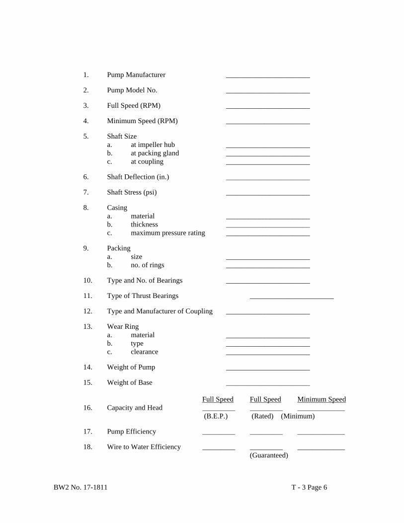
BW2 No. 17-1811 T - 3 Page 6
1. Pump Manufacturer _______________________
2. Pump Model No. _______________________
3. Full Speed (RPM) _______________________
4. Minimum Speed (RPM) _______________________
5. Shaft Size a. at impeller hub _______________________ b. at packing gland _______________________ c. at coupling _______________________
6. Shaft Deflection (in.) _______________________
7. Shaft Stress (psi) _______________________
8. Casing
a. material _______________________ b. thickness _______________________ c. maximum pressure rating _______________________
9. Packing
a. size _______________________ b. no. of rings _______________________
10. Type and No. of Bearings _______________________
11. Type of Thrust Bearings _______________________
12. Type and Manufacturer of Coupling _______________________
13. Wear Ring
a. material _______________________ b. type _______________________ c. clearance _______________________
14. Weight of Pump _______________________
15. Weight of Base _______________________
Full Speed Full Speed Minimum Speed
16. Capacity and Head _________ _________ _____________ (B.E.P.) (Rated) (Minimum)
17. Pump Efficiency _________ _________ _____________
18. Wire to Water Efficiency _________ _________ _____________
(Guaranteed)
BW2 No. 17-1811 T - 3 Page 7
19. Horsepower Required _________ _____________
20. NPSH Required 1. at design point _________ _____________ 1. at minimum speed _________ _____________
21. Impeller
2. diameter _________ _____________ 1. eye area _________ _____________
3.06 PUMP PERFORMANCE CURVES
Pump Performance Curves for full speed and minimum speed shall be furnished and shall include the following:
Head vs. Capacity Curve Pump Efficiency vs. Capacity Curve Brake Horsepower vs. Capacity Curve Wire to Water Efficiency vs. Capacity Curve NPSH Required vs. Capacity Curve
END OF SECTION
BW2 No. 17-1811 T - 4 Page 1
SECTION T - 4 MOTORS PART 1 GENERAL 1.01 SCOPE OF WORK
The work performed under this section consists of providing all labor, material, and related items required to furnish the squirrel-cage induction motors. The motors will drive the vertical in-line distribution pumps. Electrical components and equipment furnished shall be consistent with the motors provided and shall operate motors in a proper and efficient manner.
1.02 REFERENCE STANDARDS
A. NEMA MG1-20 B. ANSI
C. NEC
D. AFBMA
E. OSHA
F. NEMA MG1-12.51 (Test Procedure)
G. Requirements listed in the Specifications are to be considered additional to the standard requirements
listed above. 1.03 ACCEPTABLE MANUFACTURERS
A. U.S. Electrical Motors
B. Baldor
C. Westinghouse
D. Toshiba
E. Louis Allis
F. General Electric
G. Approved equal
1.04 SUBMITTALS
BW2 No. 17-1811 T - 4 Page 2
A. The following information shall be submitted with proposal for motors to be furnished under
these Specifications:
1. Certified data. 2. Outline dimension drawing. 3. Load accelerating capabilities described by the following curves:
a. Current vs. Time
b. RPM & Amps vs. Time
c. RPM vs. Torque and Current 4. Thrust capabilities.
B. Certified Shop Test Reports
Five copies of the original certified test reports of Electric Motor Shop Tests shall be submitted for each motor. These test reports shall be typed, not hand lettered, to assure legibility.
1.05 SHOP TESTS
A. Electric Motor Shop Test The manufacturer shall perform a complete shop test on each electrical motor and shall provide the performance and characteristics as listed in Paragraph B. The actual values of the complete test shall be measured and run in accordance to the applicable provisions for Standard Routine Motor Test Code MG 20.46 and the American Standard Test Code. All tests shall be made at the full design voltage unless specified otherwise. All tests shall be made and reported in accordance with NEMA MG1-12.51.
B. Complete short commercial test shall include but not be limited to the following test for each motor:
1. No load running current.
2. Locked rotor current.
3. Winding resistance test.
4. High potential test.
5. Current balance check.
1.06 OPERATION AND MAINTENANCE MANUALS
BW2 No. 17-1811 T - 4 Page 3
Operation and maintenance instructions shall be furnished. The manual shall be prepared specifically for this installation and shall include all drawings, wiring diagrams, etc.
PART 2 PRODUCTS 2.01 GENERAL
A. The motors shall be squirrel-cage induction motors. Each motor shall be electrically and mechanically suited for the pump to which it shall be applied. The motors shall comply with NEMA Standard MG20 and associated ASA and IEEE Standards unless specifically amended hereafter.
B. Each motor shall be compatible with the pump to which it shall be applied and the motor will
operate efficiently, without overheating or abnormal vibration.
C. Each motor shall be designed to provide a 40 year life.
D. Service Conditions
1. Location: Collin County, Texas
2. Ambient temperature range: 0º C to +40 ºC
3. Relative humidity: Outdoors
4. Area classification: Non-hazard
5. Duty: Continuous
6. Altitude: Less than 1,000 ft.
E. Ratings and Features:
1. Type motor: Induction, Vertical, C-Face NEMA design B torque curve, to serve a centrifugal pump load.
2. Horsepower: as required by pump loads (90 HP for one pump).
3. Voltage: Nominal 460 Volts
4. Phase: 3
5. Frequency: 60
6. Service factor: 1.15
7. Full load speed: to match pump speed
BW2 No. 17-1811 T - 4 Page 4
8. Insulation class: F
9. Temperature rise (by resistance): NEMA standard
10. Enclosure type: Totally enclosed, corrosion duty, epoxy coated, cast iron frame.
11. Space heaters: 120 Volts, Single Phase
12. NEMA Nominal Efficiency of 91.7% (Premium Efficiency)
13. Motor shall be Premium Duty, fully compatible with a variable frequency drive motor controller.
2.02 OPERATING CHARACTERISTICS
The manufacturer of the motors shall coordinate closely with the manufacturer of the pumps so that all physical and operational characteristics of the motors are compatible with the requirements of the pumps. The motors shall operate efficiently, without overloading, overheating or abnormal vibration, throughout the entire range of speed and load. There shall be no point on the pump curves at which the motor nameplate rating is overloaded, even momentarily. The motors shall have a service factor rating of 1.15.
2.03 BEARINGS
A. Obtain the thrust load requirements from the pump manufacturer. B. The two motor bearings (inner, by pump, and outer) shall be single row, premium quality
regreasable ball bearings, suitable for a horizontal motor. 2.04 MOTOR BALANCE
Motor vibration shall be within an amplitude, peak to peak, of 0.002 inches in any direction, measured at the bearing housing according to NEMA MG1-20.53.
2.05 TORQUE
A. Each motor shall be readily capable of starting the pump under all conditions to which it could be subjected.
B. Starting and pull-up torque shall not be 75 percent of full load torque. Minimum breakdown
torque shall not be less than 200 percent of full load torque. The foregoing torques are minimums and the starting, pull-up and breakdown torques shall satisfy the requirements of the drive.
C. Rotor Bars shall be copper or copper alloy. Aluminum bars are unacceptable.
2.06 INSULATION
A. Moisture proof premium insulation shall be used with fungus protection. B. The insulation system shall be Class F.
BW2 No. 17-1811 T - 4 Page 5
2.07 NOISE LEVEL
The noise shall not exceed 85 db on the “A” scale at 5 feet in any direction from the motor, when measured per IEEE 85.
2.08 LUBRICATION
The motor ball bearing race shall be regreasable. 2.09 STARTING DUTY
A. Each motor will be suitable for one start per hour on the average with the subsequent start being immediately after coasting to a stop after being fully loaded just prior to the stop.
B. Each motor will further be suitable for three successive starts from an initial ambient
temperature with each start beginning after the motor has coasted to a stop. 2.10 NAMEPLATES
Each motor shall have a stainless steel nameplate listing: type, frame, temperature rise, horsepower, full load current, RPM, number of phases, voltage, locked rotor amps, connection diagram, serial number, bearing numbers, oil type, number of starts per hour and number of starts per 24 hours.
2.11 LIFTING LUGS
A. Provide permanent lifting lugs designed for a minimum load of two times the motor weight for lifting the entire motor.
B. Provide lifting means for all motor parts over 100 lbs.
2.12 SPACE HEATERS
A. The space heater shall be sized so that the temperature inside the motor will be maintained above dew-point when equipment is not energized during the minimum ambient temperature specified elsewhere.
B. Space heaters shall be rated for 120 volts, single phase, 60 Hz.. Power for space heaters shall
be derived from and operated from contacts in the motor starter for that motor. 2.13 MAIN CONDUIT BOXES
The conduit box shall be installed on the motor prior to shipment and sized for the power conductors.
2.14 SHAFT COUPLING
BW2 No. 17-1811 T - 4 Page 6
Pump to motor coupling shall be coordinated with and by pump supplier. Motor must meet coupling requirements of pump.
2.15 LOAD INERTIA
Obtain the actual load WK2 (lb-ft2) from the pump manufacturer. 2.16 Motor Manufacturer shall be responsible to match the motor mounting flange with the driven
pump base. 2.17 Motors shall be primed inside and outside and painted outside with motor manufacturer’s
standard ANSI gray, after testing. 2.18 GROUNDING
Provide a grounding lead in the main conduit box. The conductor shall be sized per NEC 250. PART 3 EXECUTION 3.01 DELIVERY AND STORAGE
A. Delivery 1. Prepare motors and accessories for shipment in weatherproof tarps and support palletting.
B. Storage and Handling at Job Site
1. Store motors and accessories in an area protected from weather, moisture or possible damage.
2. Do not store materials directly on the ground.
3. Handle items to prevent damage to interior or exterior surfaces.
4. If items are stored inside the building, consideration shall be given to weight of the items and the effect of concentrated loads on the building slab, foundation, and other structural members. Contractor shall contact Owner for permission to store materials on-site.
3.02 INSTALLATION
The Contractor will receive, set in place, provide all electrical components and equipment required, and complete wiring of each motor to provide a working drive system.
3.03 ACCEPTANCE
If, after installation, a motor is found deficient with regard to Specifications, the Contractor will remedy such deficiency at Contractor’s own expense. If operative, the deficient motor will be made available for operation until such deficiency is corrected.

BW2 No. 17-1811 T - 4 Page 7
3.04 MOTOR DATA
The Owner may require the motor information on the following page from the Contractor.

BW2 No. 17-1811 T - 4 Page 8
MOTOR DATA SHEET
1. Manufacturer _______________________
2. Horsepower _______________________
2. Starting Current _______________________ (% of full load)
3. Full Load Amps _______________________
4. Full Load RPM _______________________
5. Frame Size _______________________
6. Weight _______________________
7. Noise Level (A Scale) _______________________
8. Motor Efficiency
1. full load _______________________ 2. 3/4 load _______________________ 3. ½ load _______________________ 4. 1/4 load _______________________
9. Power Factor
1. full load _______________________ 2. 3/4 load _ ______________________ 3. ½ load _______________________ 4. 1/4 load _______________________
10. Locked Rotor Amps _______________________
11. Torques (% Full Load)
1. starting _______________________ 2. pull-in _______________________ 3. pull-out _______________________
12. Critical Speed (RPM) _______________________
13. Starter Temp. Dector Type _______________________
14. WR2 (lb-ft2) _______________________
15. Power Factor Correction _______________________
END OF SECTION
BW2 No. 17-1811 T - 5 Page 1
SECTION T - 5
CONCRETE FORMWORK PART 1 GENERAL 1.01 SCOPE OF WORK
Furnish all materials, labor, tools, equipment and related items required to provide forms for cast-in-place concrete.
1.02 QUALITY ASSURANCE
A. The following publications of the American Concrete Institute (ACI) shall apply to the extent applicable to each reference thereto:
ACI 301-R81 Specification for Structural Concrete for Buildings ACI 347-78 Recommended Practice for Concrete Formwork
B. Design Criteria.
1. Design formwork for loads and lateral pressures outlined in ACI 347, wind loads as specified by
controlling local building code, and such other loads to which the forms may be subjected. Comply with the requirements of State and Federal safety standards.
2. Details of formwork shall comply with ACI 347. 3. Do not use earth cuts as forms for vertical surfaces, unless indicated on the Drawings. 4. The requirement for facing materials shall be compatible with finish requirements specified in the
section on Concrete Finishing.
C. Tolerances
1. The maximum deflection of facing materials reflected in concrete surfaces exposed to view shall be 1/240 of the span between structural members.
2. Construct formwork to insure that the concrete surfaces will comply with tolerances in ACI 301. PART 2 PRODUCTS 2.01 MATERIALS
A. Plywood used for forms shall be exterior-Type APA Class I as graded by the American Plywood Association. Plywood shall be dressed to uniform thickness without loose knots or other defects. Plywood minimum thickness shall be 5/8 inch thick.
B. Steel forms shall be free of dents and other defects which would make them susceptible to leakage or
disfigurement of the finished concrete surface. Steel forms shall be rust-free or galvanized form surfaces.
C. Form oil shall be a non-staining paraffin-base oil having a specific gravity of between 0.8 and 0.9.

BW2 No. 17-1811 T - 5 Page 2
D. Release agent used shall be non-staining.
E. Form accessories to be partially or wholly embedded in the concrete, such as ties and hangers, shall be a commercially manufactured typed. Nonfabricated wire is not acceptable. The portion remaining within the concrete shall leave no metal within one inch of the surface when the concrete is exposed to view. Spreader cones on the ties shall not exceed 7/8-inch diameter. Design form ties to prevent seepage of water along the tie.
F. Plastic form ties are not permitted.
2.02 ACCESSORIES
A. Concrete blocks may be used for slabs on grade.
B. Provide wrapped dowels or protect dowels with cardboard tubes for alignment reinforcing across expansion joints.
PART 3 EXECUTION 3.01 FORM CONSTRUCTION
A. Forms shall be tight to prevent leakage of grout or cement paste. B. Where necessary to maintain the specified tolerances, camber formwork to compensate for
anticipated deflections in the formwork due to the weight and pressure of the fresh concrete and construction loads.
C. Provide positive means of adjustment (wedges or jacks) of shores and struts. Take up all settlement during concrete placing operations. Brace forms against lateral deflections.
D. Provide temporary openings at the base of column forms and wall forms and at other points where necessary to facilitate cleaning and observation immediately before concrete is deposited.
3.02 PREPARATION OF FORM SURFACES
A. Plywood and other wood surfaces not subject to shrinkage shall be sealed against absorption of moisture from the concrete by either.
1. A field applied form oil or sealer approved by the Owner, or 2. A factory applied nonabsorptive liner.
B. When forms are coated to prevent bond with concrete, it shall be done prior to erecting forms. Do not
allow excess coating material to stand in puddles in the forms to come in contact with surfaces to which fresh concrete is to be bonded.
C. Where as-cast finishes are required, do not apply materials which will impart a stain to the concrete to
the form surfaces. Where the finished surface is required to be painted, apply material to form surfaces compatible with the type of paint to be used.
D. Dampen wood forms by sprinkling immediately before placing.
E. Clean form surfaces before use and re-use.

BW2 No. 17-1811 T - 5 Page 3
F. Assemble forms so they may be readily removed without damage to concrete surfaces. 3.03 FORMS FOR EXPOSED CONCRETE
A. Drill forms to suit ties used and to prevent leakage of concrete mortar around tie holes. Do not splinter forms by driving ties through improperly prepared holes.
B. Do not use metal cover plates for patching holes or defects in forms.
C. Provide sharp, clean corners at intersecting planes, without visible edges or offsets. Back joints with
extra studs or girts to maintain true, square intersections.
D. Place 3/4 inch x 3/4 inch chamfer strips in the corners of column, beam and wall forms where the concrete will be exposed to view.
3.04 REMOVAL OF FORMS
A. Formwork for columns, walls, sides of beams and other parts not supporting the weight of the concrete shall remain in place for a minimum of 48 hours after completion of concrete placement.
B. Formwork for beam soffits and slabs and other parts that support weight of concrete shall remain in
place until the concrete has reached its specified 28 day strength, unless otherwise permitted.
C. The shores and supports shall remain in place until the concrete has reached its specified 28 day strength, unless otherwise permitted.
D. Whenever the formwork is removed during the curing period, cure the exposed concrete by one of the
methods specified in the section on Cast in Place Concrete.
E. Remove form ties as soon as possible after form removal, not to exceed two working days. 3.05 REMOVAL STRENGTH
When formwork removal or reshoring removal is based on the concrete reaching its specified 28 day strength or a specified percentage thereof, the concrete shall be presumed to have reached this strength when either of the following conditions is met:
A. When test cylinders, field cured under the most unfavorable conditions prevailing for any portion of
the concrete represented, have reached the required strength. Except for the field curing and age at test, the cylinders shall be molded and tested as specified in the section on Cast in Place Concrete.
B. When the concrete has been cured as specified in the section on Cast in Place Concrete, for the same
length of time as the age at test of laboratory-cured cylinders which reached the required strength. The length of time the concrete has been cured in the field shall be determined by the cumulative number of days or fractions thereof, not necessarily consecutive, during which time the temperature of the air in contact with the concrete is above 50 degrees and the concrete has been damp or sealed from evaporation and loss of moisture.
END OF SECTION

BW2 No. 17-1811 T - 6 Page 1
SECTION T - 6
CONCRETE REINFORCEMENT PART 1 GENERAL 1.01 SCOPE OF WORK
Furnish all materials, labor, tools, equipment and related items required to provide and place concrete reinforcing.
1.02 QUALITY ASSURANCE
A. The specifications of the American Society for Testing and Materials (ASTM) referred to below shall apply to the extent applicable in each reference.
A 185-90a Specification for Welded Steel Wire Fabric for Concrete Reinforcement A 615-90 Specifications for Deformed and Plain Billet Steel Bars for Concrete
Reinforcement
B. The following publications of the American Concrete Institute (ACI) and the Concrete Reinforcing Steel Institute (CRSI) shall apply to the extent applicable in each reference thereto:
ACI 315-80 Manual of Standard Practice for Detailing Reinforced Concrete Structures ACI 318-O2R Building Code Requirements for the Reinforced Concrete CRSI Manual of Standard Practice, Concrete Reinforcing Steel Institute (CRSI)
C. Fabricating Tolerances. Bars used for concrete reinforcement shall meet the following requirements
for fabricating tolerances:
1. Sheared length: ± 1 inch 2. Depth of truss bars: ± 1/2 inch. 3. Stirrups, ties and spirals: ± 1/2 inch. 4. All other bends: ± 1 inch.
D. Placing tolerances. Place bars to the following tolerances:
1. Concrete cover to formed surfaces: ± 1/4 inch.
2. Top bars in slabs and beams:
i. Members 8 inches deep or less: ± 1/4 inch.
ii. Members more than 8 inches but not over 2 feet deep: ± 1/2 inch. iii. Members more than 2 feet deep: ± 1 inch.
B. Crosswise of members: spaced evenly within 2 inches.
C. Lengthwise of members: ± 2 inches.
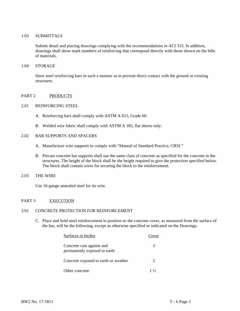
BW2 No. 17-1811 T - 6 Page 2
1.03 SUBMITTALS
Submit detail and placing drawings complying with the recommendations in ACI 315. In addition, drawings shall show mark numbers of reinforcing that correspond directly with those shown on the bills of materials.
1.04 STORAGE
Store steel reinforcing bars in such a manner as to prevent direct contact with the ground or existing structures.
PART 2 PRODUCTS 2.01 REINFORCING STEEL
A. Reinforcing bars shall comply with ASTM A 615, Grade 60.
B. Welded wire fabric shall comply with ASTM A 185, flat sheets only. 2.02 BAR SUPPORTS AND SPACERS
A. Manufacture wire supports to comply with “Manual of Standard Practice, CRSI.”
B. Precast concrete bar supports shall use the same class of concrete as specified for the concrete in the structures. The height of the block shall be the height required to give the protection specified below. The block shall contain wires for securing the block to the reinforcement.
2.03 THE WIRE
Use 16-gauge annealed steel for tie wire. PART 3 EXECUTION 3.01 CONCRETE PROTECTION FOR REINFORCEMENT
C. Place and hold steel reinforcement in position so the concrete cover, as measured from the surface of the bar, will be the following, except as otherwise specified or indicated on the Drawings.
Surfaces in Inches Cover
Concrete cast against and 3 permanently exposed to earth
Concrete exposed to earth or weather 2
Other concrete 1 ½
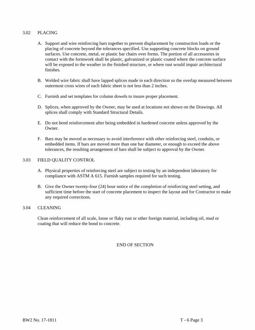
BW2 No. 17-1811 T - 6 Page 3
3.02 PLACING
A. Support and wire reinforcing bars together to prevent displacement by construction loads or the placing of concrete beyond the tolerances specified. Use supporting concrete blocks on ground surfaces. Use concrete, metal, or plastic bar chairs over forms. The portion of all accessories in contact with the formwork shall be plastic, galvanized or plastic coated where the concrete surface will be exposed to the weather in the finished structure, or where rust would impair architectural finishes.
B. Welded wire fabric shall have lapped splices made in each direction so the overlap measured between
outermost cross wires of each fabric sheet is not less than 2 inches.
C. Furnish and set templates for column dowels to insure proper placement.
D. Splices, when approved by the Owner, may be used at locations not shown on the Drawings. All splices shall comply with Standard Structural Details.
E. Do not bend reinforcement after being embedded in hardened concrete unless approved by the
Owner.
F. Bars may be moved as necessary to avoid interference with other reinforcing steel, conduits, or embedded items. If bars are moved more than one bar diameter, or enough to exceed the above tolerances, the resulting arrangement of bars shall be subject to approval by the Owner.
3.03 FIELD QUALITY CONTROL
A. Physical properties of reinforcing steel are subject to testing by an independent laboratory for compliance with ASTM A 615. Furnish samples required for such testing.
B. Give the Owner twenty-four (24) hour notice of the completion of reinforcing steel setting, and
sufficient time before the start of concrete placement to inspect the layout and for Contractor to make any required corrections.
3.04 CLEANING
Clean reinforcement of all scale, loose or flaky rust or other foreign material, including oil, mud or coating that will reduce the bond to concrete.
END OF SECTION

BW2 No. 17-1811 T – 7 Page 1
SECTION T - 7
CAST IN PLACE CONCRETE PART 1 GENERAL 1.01 SCOPE OF WORK
A. This specification shall govern the materials used, the storing and handling of materials, and the proportioning and mixing for structural concrete.
B. The concrete shall be composed of Portland cement, aggregates (fine and coarse), and water, proportioned and mixed as hereinafter provided.
PART 2 PRODUCTS 2.01 CEMENT
A. The cement shall be Type I or Type II, Portland cement conforming to ASTM Designation C 150. B. For verification of cement strength requirements, both the tensile and compressive tests shall be used. C. Only one brand of cement will be permitted in any one structure unless otherwise authorized by
Owner. 2.02 MIXING WATER
A. Water for use in concrete and for curing shall be free from oils, acids, organic matter, or other deleterious substances and shall not contain more than 1,000 parts per million of chlorides such as C1 nor more than 1,000 parts per million of sulfates such as SO4.
B. Water from municipal supplies approved by the State Health Department will not require testing, but water from other sources will be sampled and tested before use in structural concrete. A sample of approximately one gallon will be submitted for test and approval.
C. Tests shall be made in accordance with the “Standard Method of Test for Quality of Water to be used in Concrete” (AASHO Method T 26), except where such methods are in conflict with provisions of this specification.
2.03 COARSE AGGREGATE
Coarse aggregate shall consist of durable particles of gravel, crushed blast furnace slag, crushed stone, or combinations thereof, and shall be free from injurious amounts of salt, alkali, vegetable matter, or other objectionable material, either free or as an adherent coating, and its quality shall be reasonably uniform throughout. It shall not contain more than 0.25 percent by weight of clay lumps, more than 1.0 percent by weight of shale, nor more than 5 percent by weight of laminated and/or friable particles. It shall have a wear of not more than 40 percent when tested in accordance with ASTM Test C131. Coarse aggregate shall be washed.
When tested by approved methods, the coarse aggregate, including combinations of aggregates when used, shall conform to the following grading requirements:

BW2 No. 17-1811 T – 7 Page 2
Sieve Size Percent Retained
2" 0 1 ½" 0 to 5 3/4" 10 to 40 ½" 40 to 75 3/8" 70 to 90 No. 4 95 to 100
2.04 FINE AGGREGATE
Fine aggregate shall consist of clean, hard, durable, and uncoated particles of natural or manufactured sand or a combination thereof, with or without a mineral filler. It shall be free from injurious amounts of salt, alkali, vegetable matter, or other objectionable material, and it shall not contain more than 0.5 percent by weight of clay lumps.
When tested by approved methods, the fine aggregate or combinations of aggregates, including mineral filler, shall conform to the following grading requirements:
Sieve Size Percent Retained
3/8" 0 No. 4 0 to 5 No. 8 0 to 20 No. 16 15 to 50 No. 30 35 to 75 No. 50 70 to 90 No. 100 90 to 100 No. 200 97 to 100
2.05 ADMIXTURES
An “air-entraining” admixture shall be used in all concrete. The admixture shall meet the requirements of ASTM Designation C 260. The concrete shall be designed to entrain 5 to 6 percent air.
A “retardant-densifier” admixture may be used. This admixture shall meet the requirements of Type A, B, or D admixture as specified in ASTM Designation C 494.
Owner’s approval is required for admixtures manufactured by other than: Gifford-Hill, Master Builders, or Sika Chemical.
PART 3 EXECUTION 3.01 STORAGE OF CEMENT
All cement shall be stored in well-ventilated, weatherproof buildings or approved bins which will protect it from dampness or absorption of moisture. Storage facilities shall be ample and each shipment of packaged cement shall be kept separated to provide easy access for identification and inspection.

BW2 No. 17-1811 T – 7 Page 3
3.02 STORAGE OF AGGREGATE
The method of handling and storing concrete aggregate shall prevent contamination with foreign materials. If the aggregates are stored on the ground, the sites for the stockpiles shall be clear of all vegetation and level. The bottom layer of aggregate shall not be disturbed or used without recleaning.
When conditions require the use of two or more sizes or aggregates, they shall be separated to prevent intermixing. Where space is limited, stockpiles shall be separated by physical barriers.
Methods of handling aggregates during stockpiling and subsequent use shall be such that segregation will be minimized.
3.03 MEASUREMENT OF MATERIALS
The measurement of the materials, except water, used in batches of concrete shall be by weight. Where sacked cement is used, the quantities of material per batch shall be based upon using full bags of cement. Batches involving the use of fractional bags will not be permitted.
Allowances shall be made for the water content in the aggregates.
3.04 MIXING
A. Mix Design
It shall be the responsibility of the Contractor to furnish the mix design, using a Coarse Aggregate Factor acceptable to Owner’s Representative, for the class of concrete specified. The mix shall be designed by a qualified concrete technician to conform to the requirements contained herein.
The Contractor shall perform, at his own expense, the work and testing required to substantiate the design. The testing of strength specimens shall be performed by a reputable laboratory approved by the Owner. Complete concrete design data shall be submitted to the Owner for approval.
A trial batch shall be made and tested using all the proposed ingredients prior to the placing of concrete and when the aggregate and/or brand of cement is changed. Trial batches shall be made in the mixer to be used on the job. When Transit Mix concrete is to be used, the trial designs shall be made in a transit mixer representative of the mixers to be used. Batch size shall not be less than 50 percent of the rated mixing capacity of the truck.
Mix designs from previous or concurrent jobs may be used without trial batches if it is shown that no substantial change in any of the proposed ingredients has been made, and if adequate historical strength data can be presented.
B. Consistency
The consistency of the concrete as placed should allow the completion of all finishing operations without the addition of water to the surface. When field conditions are such that additional moisture is needed for the final concrete surface finishing operation, the required water shall be applied to the surface by fog spray only, and shall be held to a minimum. The concrete shall be workable, cohesive, possess satisfactory finishing qualities, and be of the stiffest consistency that can be placed and vibrated into a homogeneous mass. Excessive bleeding shall be avoided.

BW2 No. 17-1811 T – 7 Page 4
Slump requirements shall be as follows:
Desired Slump = 4"; Maximum Slump = 6"
No concrete shall be permitted with slump in excess of the maximum. The Contractor will be allowed to use a high-range water reducer, or super-plasticizer conforming to ASTM C494, Type F (other types not acceptable) to increase slump over 4" in accordance with manufacturer’s recommendations if desired.
C. Quality of Concrete
The concrete shall be uniform and workable. The cement content, maximum allowable water cement ratio, and the strength requirements of the concrete shall conform to either of the following mix requirements:
Class A Class B Class C
Sacks of Cement per Cubic Yard 5 6 4 Minimum 28-Day Compressive strength 3,000psi 4,000 psi 2,000 psi Minimum 7-Day Beam Strength (ASTM C78) 500 psi 600psi 330 psi Maximum Water Cement Ratio 6.5 gal/sk 5.5 gal/sk 8.0 gal/sk
During the progress of the work, the Contractor shall cast test cylinder and beams as a check on the compressive and flexural strength of the concrete actually placed. A test shall be defined as the average of the breaking strength of two cylinders or two beams, as the case may be.
Two test beams and two test cylinders shall be required for each 60 cubic yards of concrete placed. Generally, for small placements on structures such as catch boxes, guard post foundations, and other items requiring less than 10 cubic yards, no testing shall be required. However, on structures where concrete structural strength is critical, such as retaining walls or load carrying beams or members, one set of two test specimens and cylinders shall be required for each pour as described above, regardless of size. For each two test specimens, one shall be laboratory cured and one shall be field cured using the same curing method utilized for structural concrete.
The Contractor shall insure that the testing laboratory maintains curing facilities for the purpose of curing test specimens, and shall pay all testing laboratory charges.
The Contractor shall supply to the Owner certified copies of the test results. If the required 7-day strength is not secured, changes in the batch design shall be made and, at the discretion of Owner, concrete represented by the test specimens shall be removed and replaced at no expense to the City.
When control of concrete quality is by 28-day compressive tests, job control shall be by 7-day compressive tests which are shown to provide the required 28-day strength, based on results from trial batches.
D. Mixing Conditions
The concrete shall be mixed in quantities required for immediate use. Any concrete which is not

BW2 No. 17-1811 T – 7 Page 5
in place within the limits outlined in this specification shall not be used. Retempering of concrete shall not be permitted.
In threatening weather, which may result in conditions that will adversely affect quality of the concrete to be placed, the Owner may order postponement of the work. Where work has been started and changes in weather conditions required protective measures, the Contractor shall furnish adequate shelter to protect the concrete against damage from rainfall or from freezing temperatures.
E. Mixing and Mixing Equipment
All equipment, tools, and machinery used for hauling materials and performing any part of the work shall be maintained in such condition to insure completion of the work underway without excessive delays for repairs or replacements. The mixing shall be done in a batch mixer of approved typed and size that will produce uniform distribution of the material throughout the mass. Mixers may be either the revolving drum type or the revolving blade type and shall be capable of producing concrete meeting the requirements of these specifications.
Whenever a concrete mixer is not adequate or suitable for the work, it shall be removed from the site upon a written order from the Owner and a suitable mixer provided by the Contractor.
Improperly mixed concrete shall not be placed in the structure.
The use of ready-mixed concrete shall be permitted, provided the batching plant and mixer trucks meet the requirements of this specification.
Hand-mixing of concrete shall be permitted only for small placements or in case of an emergency, and then only on the authorization of the Owner. Hand-mixed batches shall not exceed a two-bag batch in volume.
3.05 PLACING, FINISHING, AND CURING
A. Placing
Concrete shall be placed utilizing forms of either wood or steel. Forms shall be practically mortar-tight, rigidly braced, and strong enough to prevent bulging between supports. Forms shall be maintained to the proper alignment and grade during concrete placement.
The Contractor shall give the Owner sufficient advance notice before placing concrete in any unit of the structure to permit the inspection of forms, reinforcing steel placement, and other preparations.
Concrete shall be placed before any setup occurs, otherwise the entire batch will be discarded. No retempering will be allowed. Concrete shall be placed within one hour and thirty minutes of batches.
The method of handling, placing, and consolidation of concrete shall minimize segregation and displacement of the reinforcement and produce a uniformly dense and compact mass. Concrete shall not be allowed to free fall more than 5 feet. Rodding or vibrating shall be performed to minimize honeycombing. After removal of formwork, all honeycombing, spalled edges, and irregularities shall be repaired.

BW2 No. 17-1811 T – 7 Page 6
Contractor shall take any steps necessary to lower the natural water table if required for placement of concrete. No concrete shall be placed in standing water.
1. Formed surfaces which will be covered either by soil or by further construction shall require no special treatment or finish.
2. Formed surfaces which will be visible shall have all surface irregularities patched; then the entire
surface shall be rubbed with a cement paste to create a uniform surface. Maximum allowable build-up of the rubbing material shall be 1/4".
3. Slabs which will receive a finished flooring material, such as vinyl tile, shall receive a smooth
steel trowel finish. Steel troweling may be done by either hand or machine.
4. Slabs which will receive no finished flooring shall be wood floated and broom finished.
B. Finishing
Concrete finishing shall be as specified in the section on Concrete Finishing.
C. Curing
All concrete shall be cured for a minimum period of five days. Start curing operations as soon as possible after finishing is complete without damaging the finish. Do not allow fresh concrete surfaces to remain overnight without a curing system. Curing shall be by one of the following methods:
1. Form Curing
When forms are left in contact with the concrete, other curing methods shall not be required.
2. Water Curing
All surfaces of the concrete shall be kept wet continuously for the required curing time by the application of saturated cotton mats, by ponding, or by water spray.
3. Membrane Curing
Type I (resin base only) membrane curing compound may be used. Membrane spray shall be applied in a manner to insure a uniform membrane with no gaps.
END OF SECTION

BW2 No. 17-1811 T – 8 Page 1
SECTION T - 8
PORTLAND CEMENT CONCRETE PART 1 GENERAL 1.01 SCOPE OF WORK
A. This section specifies the requirements for Portland cement concrete, including materials, proportioning, batching, mixing, delivering, and testing.
B. Portland cement concrete shall be composed of Portland cement, fine aggregate, coarse aggregate,
water, and admixtures, as approved, all proportioned and mixed as specified herein.
C. Classes of Concrete
1. Classes of concrete are designated by a numeral indicating the minimum 28-day compressive strength in pounds per square inch as determined by ASTM C 39.
2. Each class of concrete may consist of one or more mixes determined by the maximum size of aggregate, cement factor, and types of admixtures or special aggregates.
3. Each design mix within a class shall be considered as a specific type and shall require approval prior to use.
1.02 DESIGN CRITERIA
A. General Requirements
1. A design for a concrete mix shall have a minimum water content per cubic yard of concrete consistent with the required slump, a cement content corresponding to the appropriate water-cement ratio, the specified maximum size of coarse aggregate, and the required percentage of fine aggregate. Design mixes shall be as recommended by ACI 211.1 for normal concrete. Trial mix water-cement ratio shall be in accordance with ACI 211.1 as determined by the type of structure and exposed conditions and shall be adjusted to meet specified design mix requirements. Design mixes shall be tested by the Contractor’s approved testing laboratory service for conformance to contract requirements and submitted to the Owner for approval.
2. The design mixes for each class of concrete used shall be as determined by the Contractor through an approved testing laboratory service and as approved by the Owner to produce the results as specified herein.
3. For each class of concrete there shall be as many design mixes as required for the different combinations or types of ingredients anticipated to cover the work.
B. Design Strength
Design for concrete mixes shall be based on the required over-design factor according to ASTM C 94 and assuming a coefficient of variation equal to 15. Each class of concrete shall be designed so that not more than 10 percent of the strength tests will have values less than the specified strength. The average of any three consecutive strength tests shall be equal to or greater than the specified strength. Where a class is not indicated, Class 4000 concrete shall be used.

BW2 No. 17-1811 T – 8 Page 2
1.03 QUALITY ASSURANCE
A. Design Mix
1. Once a design mix for any class of concrete is approved, the mix shall not be varied as to source,
quantity, quality, grading of materials, proportioning, or in any other way. 2. All proposed mix changes shall be accomplished by preparing a new design mix and obtaining
the Owner’s approval as specified hereinbefore.
B. Sampling and Testing
Concrete ingredients shall be sampled prior to use and shall be tested by the Contractor’s approved testing laboratory service in accordance with the methods specified.
C. Slump
The slump range at point of delivery for concrete shall be maintained within the following limits:
1. Concrete pavement, pavement base, Sidewalk and incidental construction: 2-3 in.
2. Unreinforced concrete other than the above: 1-3 in. 3. Reinforced concrete: 3-4 in.
D. Minimum Cement Content
Minimum Cement content shall be as follows:
Min. Compressive
Strength Min. Cement Class @ 28 days Content B 3,000 470 lb/cu yd C 4,000 564 lb/cu yd D 5,000 611 lb/cu yd
E. Reference Standards Applicable to this Section
1. ACI: American Concrete Institute
i. 211.1 Standard Practice for Selecting Proportions for Normal, Heavyweight, and Mass Concrete
ii. 304: Recommended Practice for Measuring, Mixing, Transporting, and Placing Concrete
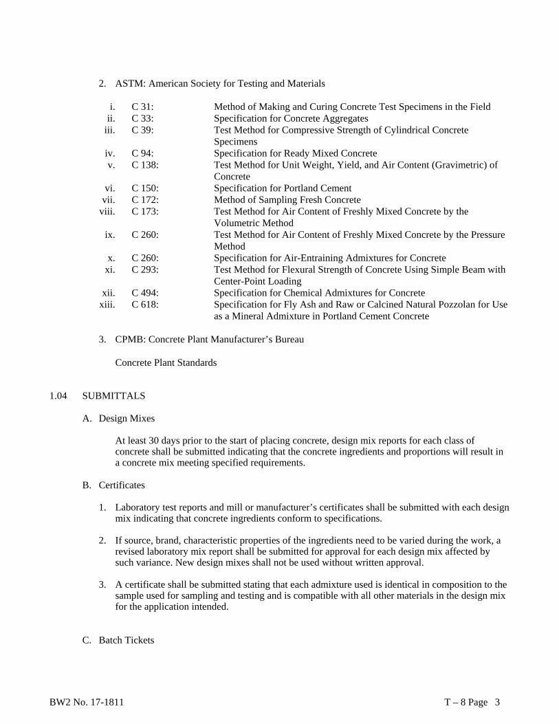
BW2 No. 17-1811 T – 8 Page 3
2. ASTM: American Society for Testing and Materials
i. C 31: Method of Making and Curing Concrete Test Specimens in the Field
ii. C 33: Specification for Concrete Aggregates iii. C 39: Test Method for Compressive Strength of Cylindrical Concrete
Specimens iv. C 94: Specification for Ready Mixed Concrete v. C 138: Test Method for Unit Weight, Yield, and Air Content (Gravimetric) of
Concrete vi. C 150: Specification for Portland Cement
vii. C 172: Method of Sampling Fresh Concrete viii. C 173: Test Method for Air Content of Freshly Mixed Concrete by the
Volumetric Method ix. C 260: Test Method for Air Content of Freshly Mixed Concrete by the Pressure
Method x. C 260: Specification for Air-Entraining Admixtures for Concrete
xi. C 293: Test Method for Flexural Strength of Concrete Using Simple Beam with Center-Point Loading
xii. C 494: Specification for Chemical Admixtures for Concrete xiii. C 618: Specification for Fly Ash and Raw or Calcined Natural Pozzolan for Use
as a Mineral Admixture in Portland Cement Concrete
3. CPMB: Concrete Plant Manufacturer’s Bureau
Concrete Plant Standards 1.04 SUBMITTALS
A. Design Mixes At least 30 days prior to the start of placing concrete, design mix reports for each class of concrete shall be submitted indicating that the concrete ingredients and proportions will result in a concrete mix meeting specified requirements.
B. Certificates
1. Laboratory test reports and mill or manufacturer’s certificates shall be submitted with each design mix indicating that concrete ingredients conform to specifications.
2. If source, brand, characteristic properties of the ingredients need to be varied during the work, a
revised laboratory mix report shall be submitted for approval for each design mix affected by such variance. New design mixes shall not be used without written approval.
3. A certificate shall be submitted stating that each admixture used is identical in composition to the
sample used for sampling and testing and is compatible with all other materials in the design mix for the application intended.
C. Batch Tickets
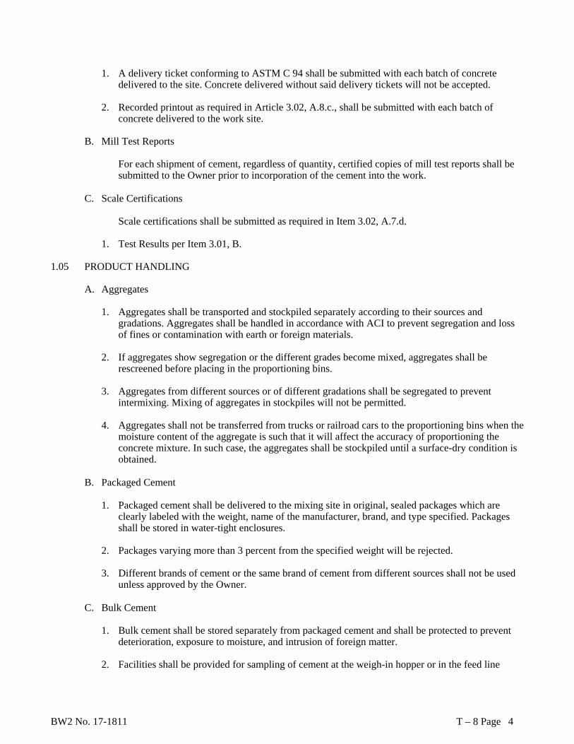
BW2 No. 17-1811 T – 8 Page 4
1. A delivery ticket conforming to ASTM C 94 shall be submitted with each batch of concrete delivered to the site. Concrete delivered without said delivery tickets will not be accepted.
2. Recorded printout as required in Article 3.02, A.8.c., shall be submitted with each batch of
concrete delivered to the work site. B. Mill Test Reports
For each shipment of cement, regardless of quantity, certified copies of mill test reports shall be submitted to the Owner prior to incorporation of the cement into the work.
C. Scale Certifications
Scale certifications shall be submitted as required in Item 3.02, A.7.d.
1. Test Results per Item 3.01, B.
1.05 PRODUCT HANDLING
A. Aggregates
1. Aggregates shall be transported and stockpiled separately according to their sources and gradations. Aggregates shall be handled in accordance with ACI to prevent segregation and loss of fines or contamination with earth or foreign materials.
2. If aggregates show segregation or the different grades become mixed, aggregates shall be
rescreened before placing in the proportioning bins.
3. Aggregates from different sources or of different gradations shall be segregated to prevent intermixing. Mixing of aggregates in stockpiles will not be permitted.
4. Aggregates shall not be transferred from trucks or railroad cars to the proportioning bins when the
moisture content of the aggregate is such that it will affect the accuracy of proportioning the concrete mixture. In such case, the aggregates shall be stockpiled until a surface-dry condition is obtained.
B. Packaged Cement
1. Packaged cement shall be delivered to the mixing site in original, sealed packages which are
clearly labeled with the weight, name of the manufacturer, brand, and type specified. Packages shall be stored in water-tight enclosures.
2. Packages varying more than 3 percent from the specified weight will be rejected.
3. Different brands of cement or the same brand of cement from different sources shall not be used
unless approved by the Owner.
C. Bulk Cement
1. Bulk cement shall be stored separately from packaged cement and shall be protected to prevent deterioration, exposure to moisture, and intrusion of foreign matter.
2. Facilities shall be provided for sampling of cement at the weigh-in hopper or in the feed line

BW2 No. 17-1811 T – 8 Page 5
immediately before cement enters the hopper.
3. Different brands of cement or the same brand of cement from different sources shall not be used unless approved by the Owner.
PART 2 PRODUCTS 2.01 MATERIALS
A. Portland Cement
1. ASTM C 150, Type I or Type II
B. Admixtures
1. Chemical Admixtures: ASTM C 494.
2. Other Pozzolanic Admixtures: ASTM C 618.
3. Calcium Chloride: The use of calcium chloride is prohibited.
4. Air-Entraining Admixtures: ASTM C 260.
C. Water
1. Potable, from municipal supplies approved by the State or City Health Department.
D. Concrete Aggregate
1. Coarse Aggregate: Gravel, crushed gravel, or crushed stone, conforming to ASTM C 33.
2. Fine Aggregate: Washed natural sand or manufactured sand, conforming to ASTM C 33. PART 3 EXECUTION 3.01 FIELD QUALITY CONTROL
A. Concrete Sampling
The Contractor shall furnish molds and concrete required for casting specimens and for the specified sampling and testing in accordance with ASTM C 172.
B. Concrete Testing
1. All testing shall be performed by a licensed or certified testing laboratory approved by the
Owner. The Contractor will provide and pay for all concrete testing as follows:
Slump and air content tests for each 50 cu. yd. or fraction thereof, placed.
2. Yield test, unit weight tests for each 100 cu. yd. or fraction thereof, placed.
BW2 No. 17-1811 T – 8 Page 6
3. Compressive strength test with one set of four standard cylinders made and cured in accordance with ASTM C 31 for each 100 cu. yd. or fraction thereof, placed. Compression tests shall be performed at the following time intervals:
First Cylinder - after 7 days of curing. Second and Third Cylinder - after 28 days of curing. Fourth Cylinder shall be retained as a spare.
Tests shall be in accordance with the following: Unit Weight, Yield, Air Content, Cement Content, and Unit Weight: ASTM C 138 Slump: ASTM C 143
Compressive Strength: ASTM C 39 Chemical Additives: ASTM C 494 and as required by the Owner Air Content: ASTM C 173 or C 231, as applicable
3.02 MIX EQUIPMENT
A. Batching Plant
1. General
Before mixing and delivery of concrete, the plant may be inspected and subject to approval by the Owner.
2. Arrangement
Separate bins or compartments shall be provided for each size or classification of aggregate and for each type of bulk Portland cement.
B. Compartments
1. The compartments shall be of ample size and so constructed that materials will be separated under
working conditions. The batching plant shall be equipped so that the flow of each material into its batcher is stopped automatically when the designated weight has been reached.
2. Weighing hoppers shall be constructed so as to eliminate accumulations of materials.
3. Aggregates may be weighed in separate weight batchers with individual scales or cumulatively in
one batcher on one scale. Bulk cement shall be weighed on a separate scale in a separate weight batcher.
4. Water may be measured by weight or by volume. If measured by weight, water shall not be
weighed cumulatively with another ingredient.
5. Batching controls shall be interlocked so that the charging mechanism cannot be opened until the scales have returned to zero. These requirements shall be satisfied by a semi-automatic batching system as defined in the CPMB’s Concrete Plant Standards, with interlocking as described herein, or by an automatic batching system as defined in the Concrete Plant Standards.
6. Facilities shall be provided for obtaining representative samples of aggregate from each of the
bins or compartments for test purposes.
7. Delivery of materials from the batching equipment shall be within limits specified in ASTM C 94.
BW2 No. 17-1811 T – 8 Page 7
C. Water Batcher
1. Equipment for batching water and admixtures shall be provided at the batching plant, except in
cases where mixing has been authorized by the Owner to be performed at the jobsite in paving mixes or in truck mixers.
2. A suitable device shall be provided that is capable of measuring mixing water within the specified requirements for each batch. The mechanism for delivering water to the mixers shall be such that leakage will not occur when the valves are closed.
3. The filing and discharge valves for the water batcher shall be so interlocked that the discharge valve cannot be opened before the filling valve is fully closed.
D. Admixture Dispensers
1. Measuring devices for admixture shall be capable of ready adjustment to permit varying the
quantity of admixture to be batched. The dispenser for admixtures shall be interlocked with the batching and discharging operations so that the batching and discharging of admixture will be automatic.
2. Non-interlocked dispensers may be permitted, provided that the calibration of the dispensers is checked at intervals as required by the Owner. The results of such calibration shall be recorded and available for inspection by the Owner.
E. Moisture Control
1. At the time of batching, all aggregates shall have been dried or drained sufficiently to result in a
stable moisture content such that no visible separation of water from aggregates will take place during transportation from the proportioning plant to the point of mixing.
2. In no event shall the free moisture content of the fine aggregate at the time of batching exceed 8
percent of its saturated, surface-dry weight. The batch-to-batch uniformity of all aggregates shall be such that variations in moisture content within 1 hour do not exceed 12 lbs. in the batch quantity for 1 cu. yd. of concrete, or that a gradual change does not exceed 24 lbs. in a period of 4 hours.
3. The Contractor shall install and maintain in operating condition an electrically-actuated moisture
meter which will indicate on a readily-visible scale the percentage of moisture in the fine aggregate as it is batched, within a sensitivity of ½ percent by weight of the fine aggregate.
F. Scales
1. Scales shall be used for the accurate measurement of each of the materials entering each batch of
concrete.
a. If scales are of the dial type, the dial shall be of such size and so arranged that it may be read easily from the operating platform.
b. If scales are of the multiple beam type, the scales shall be provided with an
indicator operated by the main beam which will give positive visible evidence of over- or under-weight. The indicator shall be so designed that it will operate during the addition of the last 200 lbs. of any weighing. The over-travel of the indicator hand shall be at least one-third of the loading travel. Indicators shall be enclosed against moisture and dust.
BW2 No. 17-1811 T – 8 Page 8
c. Scales shall be tested by a commercial scale company and certified that the scales meet all requirements for weighing equipment. Certification shall be required whenever scale is relocated and at least once each 6 months. Copies of the certifications shall be provided to the Owner.
2. Recorders
1. An accurate recorder shall be provided for producing a digital printout of the batch
number and scale readings corresponding to each of the ingredients of each concrete batch, including zero initial readings. The individual ingredient shall be indicated by name or code corresponding to each weight.
2. Each printout shall indicate date and time of batching, identification number identical to
that of the concrete delivery ticket, and codes for the mix design and for the work section.
3. The printout shall be prepared in duplicate, with one copy delivered together with its corresponding delivery ticket to the site, and one to the Owner as specified hereinbefore.
4. Each recorder mechanism shall be enclosed in a locked, dust-tight cabinet and shall be
placed in a position convenient for observation.
3. Protection Weighing, indicating, and control equipment shall be insulated against vibration or movement of other operation equipment in the plant.
G. Concrete Mixers
1. General
i. Mechanically-operated batch mixers of the revolving drum type or pan type shall be used for
mixing concrete, except that batches not exceeding 1/3 cu. yd. may be hand-mixed. ii. A metal plate shall be attached on each mixer showing the rated capacity and the drum’s
speed of rotation. A copy of the manufacturer’s design showing dimensions and arrangements of blades shall be available to the Owner.
iii. The interior of each mixer shall be free of accumulations that will interfere with mixing action. Pick-up and throw-over blades of the revolving drum mixer shall be replaced when any part or section is worn as much as 10 percent below the original dimension.
2. On-Site Mixers
i. On-site mixing shall be accomplished in paving or stationary type mixers. Mixers shall be
operated at the speeds recommended by the mixer manufacturer, except that revolving drum mixers shall make neither less than 14 nor more than 18 revolutions per minute.
ii. The mixing time shall start when all cement, aggregates, and initial water have entered the drum.
The mixer shall be charged so that some of the mixing water will enter the drum in advance of the cement and aggregates. All of the mixing water shall be in the drum by the end of the first one-fourth of the specified mixing time. Water used to flush down the blades after charging shall be accurately measured and included in the quantity of mixing water.
iii. A timing device shall be provided to ensure that the batch cannot be discharged until the required mixing time has elapsed.
BW2 No. 17-1811 T – 8 Page 9
iv. The total elapsed time between the intermingling of damp aggregates and the discharging of the completed mix shall not exceed 30 minutes.
3.03 MIXING AND DELIVERY
A. General Concrete deposited in quantities greater than 2 cu. yd. shall be truck-mixed concrete, mixed and delivered in accordance with the requirements of ASTM C 94. Truck mixers shall be equipped with water tanks and measuring devices for positive measurement of mixing water.
B. Site Mixing
Mixing of batches of 2 cu. yd. and more shall continue 60 seconds plus 60 seconds for each additional cubic yard or portion thereof.
C. Hand Mixing
1. Hand-mixed concrete shall be made in batches not larger than 1/3 cu. yd. and shall be mixed on a water-tight, level platform.
2. Coarse aggregate shall be measured in measuring boxes, spread on the platform and the fine
aggregate spread on the coarse aggregate. Total depth of the two layers shall not exceed 1 ft. The dry cement shall be spread on the aggregate and the whole dry mass shall be turned a minimum of two times. Clean water shall then be evenly added and the whole mass shall be turned a minimum of three times, not including placing in the carriers and forms.
END OF SECTION
BW2 No. 17-1811 T - 9 Page 1
SECTION T - 9
CONCRETE FINISHING PART 1 GENERAL 1.01 SCOPE OF WORK
This section specifies the requirements for:
A. The repairing of surface defects. B. Finishing of concrete surfaces including both formed and unformed. C. Sealing of concrete surfaces.
1.02 REFERENCE STANDARDS
A. Corps of Engineers (CRD). CRD C-48-73, Corps of Engineers’ Specification for Permeability of Concrete
B. American Concrete Institute publication ACI 301, Specification for Structural Concrete for Buildings. 1.03 SUBMITTALS
Product Data. When substitutions are proposed by the Contractor for acceptable brands of materials specified herein, submit brochures and samples of proposed substitutions to the Owner for approval before delivery to the project. The submittal shall include the manufacturer’s installation and/or application procedures. Submittals shall be made on the following products. A. Sealer B. Latex Bonding Agent
PART 2 PRODUCTS 2.01 MATERIALS
A. Sealer B. Sikagard Cure/Hard, manufactured by Sika Corporation. C. Approved equal
1 Latex Bonding Agent. Latex bonding agent shall be a non-re-emulsifiable latex base liquid
formulated for bonding wet concrete to hardened concrete and for mixing with cement mortar. Bonding agent shall be suitable for use under continuously submerged conditions.
PART 3 EXECUTION 3.01 REPAIRING SURFACE DEFECTS
A. Defective Areas for Concrete Work. Repair defective area immediately after the removal of forms. 1. Remove honeycombed and other defective concrete down to sound concrete. Thoroughly coat the
BW2 No. 17-1811 T - 9 Page 2
surface with a latex bonding agent. The bonding agent must be used in conformance with the manufacturer’s recommendations and instructions.
2. Make patching mortar of the same materials and of approximately the same proportions as
concrete, except omit coarse aggregate. Prepare mortar with not more than 1 part cement to 2-1/2 parts sand by damp loose volume. A latex bond agent shall be added to the mortar. Substitute white Portland cement for part of the gray Portland cement on exposed concrete in order to produce a color matching the color of surrounding concrete. Determine color by making a trial patch.
3. While the bonding coat is still tacky, apply the premixed patching mortar. Thoroughly
consolidate the mortar into place and strike off to leave the patch slightly higher than the surrounding surface. To permit initial shrinkage, leave undisturbed for at least one hour before final finishing. Keep the patched area damp for 7 days. Do not use metal tools in finishing patches in a formed wall which will be exposed.
B. Tie Holes. Patch the holes immediately after removal of forms. After cleaning the tie hole, patch as
submitted to the Owner for approval. The patching material shall be an epoxy grout.
C. Proprietary Materials. If approved by the Owner, proprietary compounds for adhesion or as patching ingredients may be used, in lieu of or in addition to, the foregoing patching procedures. Use such compounds according to the manufacturer’s recommendations.
3.02 FINISHING OF FORMED SURFACES
A. Surfaces Requiring Finish. A finish is not required on surfaces concealed from view by earth, ceilings, etc. in the complete structure.
A. Smooth Form Finish
Use plywood or fiberboard linings or forms in as large sheets as practicable and with smooth, even edges and close joints.
Immediately upon stripping forms and before concrete has changed in color, remove all fins with a hammer and patch tie holes and defects.
Use a smooth form finish on all formed surfaces which are exposed to view or water in the completed structure.
B. Related Unformed Surfaces. Tops of walls and similar unformed surfaces occurring adjacent to
formed surfaces shall be struck smooth after concrete is placed. Float unformed surfaces to a texture reasonably consistent with that of the formed surfaces. Final treatment on formed surfaces shall continue uniformly across the unformed surfaces.
3.03 FINISHING SLABS AND SIMILAR FLAT SURFACES
A. Shaping to Contour. Use strike-off templates or approved compacting-type screeds riding on screed strips or edge forms to bring concrete surface to the proper contour. See the section on Concrete Formwork for edge forms and screeds.

BW2 No. 17-1811 T - 9 Page 3
B. Consolidation. Thoroughly consolidate concrete in slabs and use internal vibration in beams and girders of framed slabs and along bulkheads of slabs on grade. Obtain consolidation of slabs and floors with vibrating bridge screeds, roller pipe screeds, or other approved means. Concrete to be consolidated must be as dry as practicable. Do not permit manipulation of surfaces prior to finishing operations.
C. Tolerances for Finished Surfaces. Tolerances are checked by placing a straightedge of specified
length anywhere on the slab. The gap between slab and straightedge must not exceed the tolerance listed for the specified class.
Straight Edge Length Tolerance
Class in Feet in Inches
A 10 1/8 B 10 1/4 C 2 1/4
D. Floated Finish
1. After concrete has been placed, struck off, consolidated and leveled, do not work further until
ready for floating. Begin floating when water sheen has disappeared, or when the mix has stiffened sufficiently to permit proper operation of a power-driven float. Consolidate the surface with power-driven floats. Use hand floating with wood or cork-faced floats in locations inaccessible to a power-driven machine and on small, isolated slabs.
2. Recheck tolerance of the surface after initial floating with a 10-foot straightedge applied at not
less than two different angles. Cut down high spots and fill low spots to Class B tolerance. Immediately refloat slab to uniform, smooth, granular texture.
3. Provide a floated finish for the following: ground storage tank floors.
4. Troweled Finish
i. To obtain a troweled finish, a floated finish as previously specified must be applied. After
power floating, use a power trowel to produce a smooth surface which is relatively free of defects but which may still contain some trowel marks. Do additional trowelings by hand after the surface is produced as the trowel is moved over the surface. Thoroughly consolidate the surface by hand troweling operations.
ii. Produce a finished surface free of trowel marks, uniform in texture and appearance and conforming to Class A tolerance.
iii. Provide a troweled finish for the following: structural slabs intended as walking surfaces, i.e., pump vault slab.
F. Broom or Belt Finish
1 Immediately after completing the floated finish, draw a broom or burlap belt across the surface to
give a coarse transverse scored texture.
2 Provide a broom or belt finish for the following:

BW2 No. 17-1811 T - 9 Page 4
i. Driveways
ii. Sidewalks (including outside walking surfaces at all structures).
G. Sealer
1 Apply Sealer in strict compliance with the manufacturer’s recommendations.
2 Apply Sealer for all horizontal concrete surfaces, inside or outside, intended as walking surfaces.
3 Mask walls, doors, frames, etc., to prevent floor coating from coming in contact.
4 Rooms with concrete walls shall receive a 2-inch-high coverage of floor coating on the vertical surfaces.
H. Testing
1 Edging:
i. Locations: Walk edges at expansion joints and where needed to form a neat appearance. ii. Size: a 3/8-inch radius unless shown otherwise.
2 Workmanship: Remove marks of tooling from the surface.
3 Tooling: Omit tooling if metal divider is used.
3.04 CURING
Curing of concrete shall conform to the requirements of the section on Cast in Place Concrete.
END OF SECTION

BW2 No. 17-1811 T - 10 Page 1
SECTION T - 10
NON-SHRINK GROUT PART 1 GENERAL 1.01 SCOPE OF WORK
This section specifies the requirements for nonmetallic, nonshrink grout for leveling machinery and other equipment and at all other locations shown or reasonably implied by the Drawings.
1.02 REFERENCE STANDARDS
A. American Society for Testing and Materials (ASTM). ASTM C 309 Liquid Membrane-Forming Compounds for Curing Concrete.
B. Corps of Engineers (CRD). CRD C 621, Corps of Engineers’ Specification for Nonshrink Grout. 1.03 SUBMITTALS
Acceptable brands of materials are specified herein. If substitutions of equal quality are proposed by the Contractor, submit the following information on the proposed substitution for approval by the Owner, before delivery to the project:
A. Manufacturer’s technical literature including manufacturer’s specifications for mixing and placing of
the grout.
B. Test results of test performed by a certified independent testing laboratory showing conformance to the following:
1. CRD C 621. 2. The requirements of this specification.
1.04 MANUFACTURER’S ASSISTANCE
Manufacturers of proprietary products shall make available, at no cost and upon 72 hours’ notification, the services of a qualified, full-time employee to aid in assuring proper use of the product under job conditions.
1.05 MATERIAL DELIVERY AND STORAGE
A. Non-shrink grout shall be delivered to the project in unopened containers and shall bear intact manufacturer’s labels.
B. Store all non-shrink grout material in dry shelter and protect from moisture.
C. Containers that are torn or damaged such that the non-shrink grout material has been exposed to the
elements shall be discarded.

BW2 No. 17-1811 T - 10 Page 2
PART 2 PRODUCTS 2.01 MATERIALS
A. Non-shrink Grout. Non-shrink grout material shall be a pre-blended factory packaged material manufactured, under rigid quality control, specifically for use in transferring heavy loads. The non-shrink grout shall conform to the following requirements.
1. Grout shall contain nonmetallic natural aggregate and shall be nonstaining and
noncorrosive. Acceptable products are Gifford-Hill “Supreme”, Master Builders’ “Masterflow 713", or approved equal.
i. Corps of Engineers CRD C 621.
ii. Resist attack by oil and water. iii. Have minimum initial setting time of approximately 1 hour at 70 F. iv. Have a minimum compressive strength of 5,000 psi at 28 days. v. Free of gas-producing or gas releasing agents.
B. Water. Water used for mixing the grout shall be potable.
C. Pea Gravel. Clean pea gravel conforming to ASTM C 33 coarse aggregate graded so that at least 90
percent passes a 3/8-inch sieve and 90 percent is retained by a No. 4 sieve.
D. Membrane-Forming Curing Compound. Commercial curing compound conforming to ASTM C 309, which will not permanently discolor the grout.
PART 3 EXECUTION 3.01 PROCEDURES
Installation methods and procedures shall conform to the printed instructions of the grout manufacturer and these specifications. Where there is a conflict between these specifications and the printed instructions of the grout manufacturer, the printed instructions of the grout manufacturer shall take precedence.
3.02 SURFACE PREPARATION
A. Remove all defective concrete, laitance, dirt, oil, grease and other foreign material from concrete surfaces by bush-hammering, chipping, or other similar means, until a sound, clean concrete surface is achieved.
B. Lightly roughen the concrete, but not enough to interfere with the proper placement of grout.
C. Remove foreign materials from all surfaces in contact with grout.
D. Align, level and maintain final positioning of all components to be grouted. Coat shims with a thin
film of grease or wax to facilitate removal.
E. Provide relief holes, if required, to avoid trapping air beneath the base plate.

BW2 No. 17-1811 T - 10 Page 3
F. Take special precautions during extreme weather conditions according to the manufacturer’s written
instructions.
G. Saturate all concrete surfaces with clean water for the period of time specified by the manufacturer. Remove excess water and leave none standing.
H. Immediately before grouting, clean any contaminated surfaces.
3.03 FORMWORK
A. Build leak-proof forms that are strong and securely anchored and shored to withstand grout pressures. Forms shall be built high enough to provide a “head” of grout where it is required to force grout into difficult locations.
B. Provide enough clearance between the formwork and the area to be grouted to permit proper
placement of grout. 3.04 MIXES
A. For less than a 4-inch clearance, or where size or shape of space makes grouting difficult, grout mix shall consist of grout material and water.
B. For greater than 4-inch clearances where coarse aggregate will not obstruct free passage of the grout,
the grout may be extended by adding clean pea gravel if allowed or recommended by the grout manufacturer. Follow the manufacturer’s recommendation for the maximum amount of pea gravel that may be added.
C. Use the minimum amount of water necessary to produce a flowable grout without causing either
segregation or bleeding. 3.05 MIXING
A. Mixing of non-shrink grout shall be in strict conformance to the recommendations of the grout manufacturer.
B. Mix grout as close to the work area as possible and transport the mixture quickly and in a manner that
does not permit segregation of materials.
C. After the grout has been mixed, do not add more water for any reason 3.06 PLACING
A. Place non-shrink grouting material quickly and continuously by the most practical means permissible: pouring, pumping or under gravity pressure. Do not use either pneumatic-pressure or dry packing methods without written permission of the Owner.
B. Follow established concreting procedures observing precautions for hot and cold weather concreting
C. When practical, apply grout from one side only to avoid entrapping air.
BW2 No. 17-1811 T - 10 Page 4
D. Final installation shall be thoroughly compacted and free from air pockets. To facilitate placement, a ½-to 1-inch chain or metal strap may be pulled back and forth under the equipment during grouting. Remove chain or strap before initial set takes place.
E. Do not vibrate the placed grout mixture or allow it to be placed if the area is being vibrated by nearby
equipment, except when approved by the grout manufacturer.
F. Do not remove leveling shims for at least 48 hours after grout has been placed. After shims have been removed, fill voids with non-shrink grout.
3.07 CURING
Cure grout for 3 days after placing by keeping wet and covering with curing paper, by coating with a concrete membrane-forming curing compound, or by other approved method.
END OF SECTION

BW2 No. 17-1811 T - 11 Page 1
SECTION T - 11
PAINTING PART 1 GENERAL 1.01 SCOPE OF WORK
A. The Contractor shall furnish all paint, labor, equipment, and materials, and perform all operations required to prepare surfaces and furnish and apply all primers, paints, protective coatings, and materials as specified. This painting specification shall be utilized as applicable to this project.
B. All paintings in connection with this project shall meet the requirements of this Section of the Specifications. In case of conflict between the painting requirement of this section and other sections of the Specifications, the requirements of this section shall prevail. Tnemec products have been identified in this section for use on this project. Equivalent paint products manufactured by other paint companies may be utilized on the project as approved equals, if approved by the City.
1.02 SUBMITTALS
A. The Contractor shall submit to the Owner for approval with the work schedule the name of the mechanical paint manufacturer the Contractor proposes to use, the manufacturer’s specifications and data on the proposed paints, and detailed surface preparation, application procedures, dry mil thickness, certificates, and test reports, as required by Method 1031.2, Federal Test Method Standard 141. The Contractor shall notify all suppliers of the paint manufacturer selected, and all shop-supplied paint shall also meet these specifications. After approval of the paint manufacturer, substitutions will not be considered.
B. Any surface to be coated which will be in contact with potable water shall receive coatings which
meet the FDA requirements for accepted ingredient materials and which are listed by the U.S. Public Health Service as acceptable for potable water tank linings for interstate carrier use. Coatings shall also meet EPA requirements, ANSI/NSF Standard 61, and shall be certified by an organization accredited by ANSI. The Contractor shall certify in writing that these requirements are met. Such certification shall be furnished to the Owner as a prerequisite to final acceptance of the project by the Owner.
C. The Contractor shall submit three (3) complete sets of paint color charts for all colors manufactured
or available from the paint supplier for application of the specified finish. Do not order any paint until reviewed by the Owner.
1.03 DEFINITION OF TERMS
A. Paint
The term “paint” as used herein includes emulsions, enamels, paints, stains, varnishes, sealers, and other coatings, organic or inorganic, whether they be used as prime, intermediate, or finish coats. This definition does not include troweled or metal-sprayed coating.

BW2 No. 17-1811 T - 11 Page 2
B. Shop Painting
The term “shop painting” as referred to herein and/or on the drawings, covers operations and paint used in painting material or equipment in a shop or plant before shipment to the job site for erection or installation.
C. Field Painting
The term “field painting” as referred to herein and/or on the drawings covers the application of paint coats at the construction site. Field painting shall normally be accomplished after erection except for surfaces to be coated which are inaccessible after erection.
D. New Surfaces
New surfaces refers to unpainted surfaces of newly fabricated structures and items which are to receive paint coats.
E. Touch-Up Painting
Touch-up painting refers to the application of paint on small areas of painted surfaces to repair mars and scratches and to restore the coating to an unbroken condition.
F. Repainting
Repainting designates the cleaning and recoating of extensive areas on which the existing coatings have deteriorated or otherwise do not provide adequate surface protection.
G. Blast Cleaning
Blast cleaning designates the cleaning of surfaces by forceful impingement of abrasive particles thereon by air blast or centrifugal action and includes sandblasting and grit blasting.
H. Mechanical Surfaces
Mechanical surfaces refers to all submerged surfaces and all machinery and piping.
1.04 QUALITY CONTROL
A. The paints and the paint products mentioned in the following specifications are set up as standards of quality. Other top-of-the-line paints of nationally known and reputable manufacturers comparable in quality and type to those specified will be considered if said paints are offered by the Contractor with satisfactory data on past performance, composition, directions for use, and other information required, and if approved by the Owner. Technical bulletins alone will not be considered as sufficient proof of equality. As a part of the proof of equality, the Owner may require at the cost of the Contractor, certified reports from a nationally known, reputable, and independent testing laboratory conducting comparative tests as directed by the Owner between the product specified and the requested substitution.
The comparative tests shall have been made within two years prior to award of Contract. Paints shall be lead-free, carcinogen-free, and non-air polluting in compliance with all laws, regulations, and ordinances of the federal, state, and local governments.
BW2 No. 17-1811 T - 11 Page 3
B. All materials shall be brought to the job site in clean, original, sealed, and labeled containers bearing
the following information:
1. Name or title of material 2. Fed. Spec. number if applicable 3. Manufacturer’s stock number and date of manufacture 4. Manufacturer’s name 5. Contents by volume, for major pigment and vehicle constituents 6. Thinning and mixing instructions 7. Application instructions 8. Color name and number
C. The Owner may have the cleaning and painting tested by an independent testing laboratory during the
cleaning and painting process. Any test revealing surface preparation or painting not meeting the requirements of this section of the Specifications will be at the expense of the Contractor.
D. Contractor shall coordinate to assure surface preparation and prime coat applied by equipment
manufacturers are compatible with finish coat. 1.05 GUARANTEE
The Contractor shall guarantee all paint and painting under this contract for a minimum of 24 consecutive calendar months beginning with the date of final acceptance of this Contract. Any part or all of any paint surface which, in the opinion of the Owner, reveals any blister, peel, flake, bubble, rust, or other imperfections within the 24-month period specified above shall be, if the Owner so directs, sandblast cleaned to white metal as specified in SSPC-SP 5, and shall be primed and painted at no expense to the Owner. Such cleaning and painting shall be accomplished within 30 calendar days after the date on which the Contractor is notified by the Owner that such cleaning and painting is required. If the original paint was a substitution for that shown in the paint schedule, and the paint failure is general over two large portions of the surface, then the surface shall be primed and repainted with a paint of the Owner’s choice.
PART 2 PRODUCTS 2.01 PAINTS TO BE APPLIED
A. General
All paint and paint products furnished or applied in fulfilling the requirements of this section of the Specifications shall be products of one paint manufacturer, except where otherwise specified. The surface preparation and paints required for various types of surface and exposure are shown in the Painting Schedule. The Contractor shall coordinate to assure surface preparation and prime coat applied by equipment manufacturers are compatible with the finish coat.
B. Fabricated and Assembled Items
Fabricated and assembled items which are normally painted with special coatings in accordance with the manufacturer’s standard practice shall be touched up in the field with the manufacturer’s recommended touch-up procedures and paints to provide an appearance satisfactory to the Owner.

BW2 No. 17-1811 T - 11 Page 4
C. Safety Color Code for Marking Physical Hazards
The safety color selected for the marking of physical hazards and safety, fire fighting, and protective equipment shall be in accordance with OSHA 1910.144.
2.02 SCHEDULE
A. General
1. Materials specified are those that have been evaluated for the specific service. Products of the Tnemec Company, Inc. are listed to establish a standard of quality. Equivalent materials of other manufacturer's may be submitted on written approval of the City. As part of the proof of equality, the City will require at the cost of the Contractor, certified test reports from a nationally known, reputable and independent testing laboratory conducting comparative tests as directed by the City between the product specified and the requested substitution.
2. Requests for substitution shall include manufacturer's literature for each product giving name,
product number, generic type, descriptive information, solids by volume, recommended dry film thickness and certified lab test reports showing results to equal the performance criteria of the products specified herein. In addition, a list of five projects shall be submitted in which each product has been used and rendered satisfactory service.
3. All requests for product substitution shall be made at least 7 days prior to the bid date.
4. Any material savings shall be passed to the owner in the form of a contract dollar reduction.
5. Manufacturer's color charts shall be submitted to the City at least 20 days prior to coating and/or
paint application. General Contractor and Painting Contractor shall coordinate work so as to allow sufficient time (normally seven to ten days) for paint to be delivered to the job site.
6. Only those thinners recommended by the manufacturer shall be used.
7. AWWA C104, C203, and C205 linings and coatings for cast iron and for steel pipe shall apply
for piping except where specifically indicated otherwise in individual sections of these Specifications.
8. For purposes of determining coatings required where not specified, surfaces which are
intermittently submerged shall be considered as submerged.
9. Primer, Intermediate, and finish coats on a given item shall be provided by the same manufacturer. No mixing of coating systems will be allowed.
10. Surfaces of piping, structures, and other items requiring a schedule for buried service and another
schedule for aboveground service shall be coated as follows:
The specified underground coating shall extend a minimum of 6 inches aboveground.
The specified aboveground coating shall extend a minimum of 6 inches below the ground and shall be applied over the underground coating.

BW2 No. 17-1811 T - 11 Page 5
B. Painting Schedule
The decision of the Owner is final as to interpretation of service, use, and conditions of exposure; all thicknesses referred to are minimum dry mil thickness.
1. Ductile Piping, (Painting System No. 1)
a. General. Ductile iron surfaces subject to normal exposure conditions where corrosive atmosphere
is light to moderate. This includes the following items: exposed surfaces of ductile iron and steel piping, including fittings, valves, flanges, bolts, supports, accessories; pipe hanger brackets; electrical conduit, boxes, electrical supports, outlets (aluminum color); pipe to be later insulated; copper tubing, fittings, and valves; exposed ductwork and louvers.
b. Normal Interior Exposure
i. Surface Preparation: Clean all surfaces as per NAPF 500-03-01 Solvent Cleaning using
stiff bristle brushes to remove all grease, oil, factory-applied tar or bitumastic coatings and any other contaminants. If surface profile is equal to or greater 1.5 mils, clean as per NAPF 500-03-03 Power Tool Cleaning taking care not to burnish the metal. If the surface profile is less than 1.5 mils, abrasive blast as per NAPF 500-03-04 Brush-Off Blast Cleaning to achieve required profile.
ii. Coating System.
1. First Coat: Tnemec Series N140-1255 Pota-Pox Plus applied at 6.0 to 8.0 dry mils.
2. Second Coat: Tnemec Series 141-WH03 Epoxoline applied at 10.0 to 12.0 dry mils
3. Total minimum dry film thickness shall be 16.0 mils.
c. Exterior Exposure
i. Surface Preparation: Clean all surfaces as per NAPF 500-03-01 Solvent Cleaning using stiff bristle brushes to remove all grease, oil, factory-applied tar or bitumastic coatings and any other contaminants. If surface profile is equal to or greater 1.5 mils, clean as per NAPF 500-03-03 Power Tool Cleaning taking care not to burnish the metal. If the surface profile is less than 1.5 mils, abrasive blast as per NAPF 500-03-04 Brush-Off Blast Cleaning to achieve required profile.
ii. Coating System:
1. First Coat: Tnemec Series N69 Hi-Build Epoxoline II applied at 6.0 to 8.0 dry mils.
2. Second Coat: Tnemec Series 740 UVX applied at 3.0 to 5.0 dry mils. (Application by brush or roller may require two coats to achieve specified film thickness.)
3. Total minimum dry film thickness shall be 10.0 mils.
2. Steel, Interior Exposure (Dry Areas) (Painting System No. 2)
a. General: All non-immersed ferrous surfaces subject to moderately severe abrasive conditions.

BW2 No. 17-1811 T - 11 Page 6
This includes and is limited to non-submerged ladders, grates, checkered deck plates, and access covers; air transfer piping; pumps, motors, blowers, grilles, curbs, and other machines and equipment.
b. Weld Preparation: Weld flux and spatter shall be removed by power tool cleaning. Sharp
projections shall be ground to a smooth contour. All welds shall be ground to a smooth contour as per NACE Standard SP0178, Designation D.
c. Surface Preparation: SSPC-SP10 Near-White Metal Blast Cleaning. Angular anchor profile shall
be 1.5 to 2.5 mils as per ASTM D 4417, Method C or NACE Standard RP0287.
d. Coating System: i. First Coat: Tnemec Series 94-H2O Hydro-Zinc applied at 2.5 to 3.5 dry mils. Thin only
with approved thinner, Tnemec 41-49 or 41-3 Thinner. ii. Stripe Coat: Tnemec Series N140-15BL Pota-Pox Plus applied by brush and scrubbed
into all weld seams. In addition to weld seams, all edges, corners, bolts, rivets, pits, etc. shall receive a stripe coat.
iii. Second Coat: Tnemec Series N140-1255 Pota-Pox Plus applied at 4.0 to 6.0 dry mils. Thin only with approved thinner, Tnemec 41-4 Thinner.
iv. Third Coat: Tnemec Series N140-15BL Pota-Pox Plus applied at 4.0 to 6.0 dry mils. Thin only with approved thinner, Tnemec 41-4 Thinner.
v. Total dry film thickness shall be a minimum of 12.0 mils.
3. Steel, Buried in Contact with Soil (Painting System No. 3)
a. General: All ferrous surfaces in contact with backfill includes, but is not limited to, all buried valves, valve boxes, miscellaneous buried metals, etc.
b. Surface Preparation. SSPC-SP6 Commercial Blast Cleaning. Reference Cleaning Preparation No.
1 for description.
c. Coating System: i. One Coat: Tnemec Series 46H-413 Tneme-Tar applied at 16.0 to 20.0 dry mils.
4. Exterior Exposed Plastic (PVC & CPVC) Pipe (Painting System No. 4).
a. Surface Preparation: Hand sand to roughen pipe surface. Clean as per SSPC-SP1 Solvent Clean
with a suitable solvent to remove all inked numbers and provide a surface profile. b. Coating System:
i. First Coat: Tnemec Series N69 Hi-Build Epoxoline II applied at 2.0 to 4.0 dry mils. ii. Second Coat: Tnemec Series 740 UVX applied at 3.0 to 5.0 dry mils.
iii. Total dry film thickness shall be a minimum of 6.0 mils.
5. Galvanized Steel (Painting System No. 5)
a. Exterior Exposed Galvanized Steel
i. Surface Preparation: Abrasive blast as per ASTM D 6386. Angular anchor profile shall be 1.5 to 2.0 mils as per ASTM D 4417, Method C or NACE Standard RP0287.
ii. Coating System:
BW2 No. 17-1811 T - 11 Page 7
1. First Coat: Tnemec Series N69 Hi-Build Epoxoline II applied at 3.0 to 5.0 dry mils.
2. Second Coat: Tnemec Series 740 UVX applied at 3.0 to 5.0 dry mils. (Application by brush or roller may require two coats to achieve specified film thickness.)
3. Total minimum dry film thickness shall be 6.0 mils.
b. Interior Exposed Galvanized Steel
i. Surface Preparation: Abrasive blast as per ASTM D 6386. Angular anchor profile shall
be 2.0 to 3.0 mils as per ASTM D 4417, Method C or NACE Standard RP0287.
ii. Coating System: 1. First Coat: Tnemec Series 20 Pota-Pox at 3.0 to 5.0 dry mils. 2. Second Coat:Tnemec Series 20 Pota-Pox at 3.0 to 5.0 dry mils. 3. Total minimum dry film thickness shall be 6.0 mils.
6. Steel, Exterior Exposure (Painting System No. 6)
a. General. Exterior of steel tanks, above ground steel piping, valves, fittings, supports, and
accessories.
i. Coating. (Three-Coat Modified Hybird Urethane System)
ii. Weld Preparation: Weld flux and spatter shall be removed by power tool cleaning. Sharp projections shall be ground to a smooth contour. All welds shall be ground to a smooth contour as per NACE Standard SP0178, Designation D.
iii. Surface Preparation: SSPC-SP6 Commercial Blast Cleaning. An angular profile of 1.5
to 2.5 mils as per ASTM D 4417, Method C or NACE Standard RP0287 is required.
iv. Coating System: 1. First Coat: Tnemec Series 90-97 Tneme-Zinc applied at 2.5 to 3.5 dry mils. Thin
only with approved thinner, Tnemec 41-2 or 41-3 Thinner. 2. Second Coat: Tnemec Series 27WB Typoxy applied at 4.0 to 6.0 dry mils. (Two
coats may be required if applied by roller.) 3. Third Coat: Tnemec Series 740-Color UVX applied at 3.0 to 5.0 dry mils. Thin
only with approved thinner, Tnemec 41-68 Thinner for spray, 41-49 for brush or roller. (Two coats may be required if applied by roller.)
4. Total dry film thickness shall be a minimum of 11.0 mils.
v. For cold weather applications, Series 44- 710 Urethane Accelerator may be added to Series 90-1K97 at the rate specified on the Series 44-710 product data sheet.
vi. For cold weather applications, Series 44-712 Urethane Accelerator may be added to
Series 740 at the rate specified on the Series 44-712 product data sheet.

BW2 No. 17-1811 T - 11 Page 8
7. Steel, Interior Potable Water Service (Wetted Areas) (Painting System No. 7)
a. General. Interior of potable water tanks, access manways, accessories, etc.
b. Coating. (High Build, Zinc/Epoxy System).
c. Weld Preparation: Weld flux and spatter shall be removed by power tool cleaning. Sharp
projections shall be ground to a smooth contour. All welds shall be ground to a smooth contour as per NACE Standard SP0178, Designation D.
d. Surface Preparation: SSPC-SP10 Near-White Metal Blast Cleaning. An angular profile of 2.0 to
2.5 mils as per ASTM D 4417, Method C or NACE Standard RP0287 is required.
e. Coating System: i. First Coat: Tnemec Series 94-H2O Hydro-Zinc applied at 2.5 to 3.5 dry mils. Thin only
with approved thinner, Tnemec 41-3 or 41-49 Thinner. ii. Stripe Coat: Tnemec Series 20-1255 Pota-Pox applied by brush to all weld seams, edges,
corners, bolts, nuts and other difficult to coat areas. Thin only with approved thinner, Tnemec 41-4 Thinner.
iii. Second Coat: Tnemec Series 22-WH07 Off-White Pota-Pox 100 applied at 18.0 to 20.0 dry mils. Thin only with approved thinner, Tnemec 41-2 Thinner.
iv. Total dry film thickness shall be a minimum of 21.0 mils. v. For cold weather applications, Series 44-710 Urethane Accelerator may be added to
Series 94 H2O. First coat shall be applied horizontally or vertically. Second coat shall be applied at right angle to first coat. Finish coat shall be applied in same direction as first coat. PART 3 EXECUTION 3.01 CLEANING AND PREPARATION OF SURFACES
A. General
All surfaces to be painted shall be prepared in a workmanlike manner with the objective of obtaining a clean and dry surface. No more abrasive blasting or surface preparation than can be coated or painting in a normal working day will be permitted. The preparation of steel surfaces shall be in accordance with the applicable specifications prepared by the Steel Structures Painting Council (SSPC). Care shall be exercised not to damage adjacent work during abrasive blasting operations. Surfaces not intended to be painting shall be suitably protected from the effects of cleaning and painting operations. Fabricated, assembled items which are normally cleaned and painted in the shop in accordance with the manufacturer’s standard practice will be considered for exemption from the detailed cleaning and painting requirement set forth herein. Removable equipment adjacent to surfaces to be painted shall, if necessary, be disconnected and moved to permit cleaning and painting of said surfaces, and replaced by workmen skilled in the trades involved.

BW2 No. 17-1811 T - 11 Page 9
Primed and finish coats which are listed in the Painting Schedule are compatible finishes. The Contractor shall follow the recommendations of the paint manufacturers, subject to the approval of the Owner, to insure a good bond between coats. The standard of cleanliness for the surface preparation shall be evaluated with the use of: S.S.P.C. Pictoral Surface Preparation Standards for Painting Steel Surfaces, SSPC-Vis 1; Swedish Pictoral Standards; or NACE TM-01-70 Visual Standards. Remove all dust and abrasives from freshly blasted surfaces by vacuum cleaning, paying special attention to corners and joints of connecting members.
B. Cleaning and Preparation of Ferrous Surfaces
Surface in Exterior or Interior Atmospheric Exposure (Cleaning System No. 1).
Ferrous surfaces which will be completely and continuously in normal exterior or interior atmospheric exposure (see schedule for description) shall be cleaned in the following manner. Oil, grease, soil, drawing and cutting compounds, and other contaminants shall be removed in accordance with SSPC-SP 1, Solvent Cleaning. After oil and surface contaminants have been removed, and before abrasive blasting, all weld splatter must be removed. All rough welds and sharp edges must be ground to give a smooth, rounded contour. Exterior steel surfaces shall be blast cleaned to a Commercial finish by removing mill scale, rust, rust scale, paint or foreign material by any of the recommended methods outlined in SSPC-SP 6, Commercial Blast Cleaning. Mechanical equipment and surfaces inaccessible to blast cleaning shall be cleaned in accordance with SSPC-SP 3, Power Tool Cleaning. The blast cleaned surface shall be primed with the primer specified for atmospheric exposed steel before any rust bloom forms. Weathering of fabricated unpainted steel for any purpose will not be permitted unless the surface is to be subsequently blast cleaned of all mill scale and rust to base metal. Welds and Damaged Areas. All welds and all damaged areas of shop-primed surfaces and or field-primed surfaces shall be field cleaned, including blast cleaning, and reprimed as specified.
Cleaning and Pretreatment of Ferrous Surfaces in Underwater Exposure (Cleaning System No. 2).
Surfaces of structural components which will be subject to extended periods of immersion or as otherwise required (see schedule for description) shall be cleaned in the following manner: Oil, grease, soil, drawing and cutting compounds, and other contaminants shall be removed in accordance with SSPC-SP 1, Solvent Cleaning. After oil surface contaminants have been removed, and before abrasive blasting, all weld splatter must be removed. All rough welds and sharp edges must be ground to give a smooth, rounded contour.

BW2 No. 17-1811 T - 11 Page 10
Interior wet areas shall be blast cleaned to a near-white metal finish, removing all mill scale, rust, rust scale, paint, or foreign matter by any of the recommended methods outlined in SSPC-SP 10, Near White Blast Cleaning. Pitted areas on the tank interior shall be repaired by either filling with Tnemec Series 215 Surfacing Epoxy or Tnemec Series 63-1500 Filler and Surfacer or by welding. Epoxy filler shall be feathered smooth. Filler shall be applied between the prime coat and the succeeding coat(s). No protrusions or spatter will be allowed. Pits deeper than 1/8” shall be filled by welding. Surfaces to be coated which will not be accessible after erection shall be cleaned and painted before becoming inaccessible. In no event shall blast-cleaned surfaces stand overnight without having received the specified pretreatment and the first coat of paint prescribed by the schedule. Structural features or components which are subject in part to atmospheric exposure and in part to immersion in water shall be prepared and painted as though the entire component were subject to immersion. Pre-erected or construction period coatings shall be maintained in good condition by recleaning and touching up any areas damaged during the construction period. Prior to the field application of subsequent coats to obtain the prescribed total film thickness, soiled areas of the pre-erection coating shall be thoroughly cleaned with mineral spirits and all welds or other unpainted or damaged areas shall be cleaned, including blast cleaning, and primed as specified and in such a manner as to make them equivalent to adjacent, undamaged paint surfaces.
Cleaning of Copper, Galvanized Steel, Stainless Steel, Aluminum, and Aluminum Alloy Surfaces
Unless otherwise specifically provided, galvanized, stainless steel, and aluminum surfaces shall not be painted, but shall be washed with clean mineral spirits per SSPC-SP-1, Solvent Cleaning to remove oil and grease. Exposed copper surfaces shall be buffed or polished to bright color, the surface cleaned with mild phosphoric acid cleaner, and the finish coat applied. The preparation of copper surfaces apply only if they are to be painted.
Inspection of Surface Preparation
The Owner may inspect all details of surface preparation to insure that surfaces have been properly cleaned, that treating solutions are of the specified type and concentration and have been properly applied, that treated surfaces are free from unneutralized residue, and that surfaces are dry and ready to receive paint.
Machined Surfaces
Machine-finished and other bare metal surfaces which are not to be painted, but which will required temporary protection during construction, shall be treated with a rust preventative compound as approved by the Owner unless otherwise specifically indicated.
3.02 PAINT APPLICATION
1. General
All work shall be done in a workmanlike manner, so that the finished coating will be free from holidays, pin holes, bubbles, runs, drips, ridges, waves, laps, unnecessary brush marks, and variations in color, texture and gloss. All coats shall be applied in such manner as to produce an even film of uniform thickness.
BW2 No. 17-1811 T - 11 Page 11
The painting contractor shall furnish workers who perform quality work and who are experienced and knowledgeable in the surface preparation and application of high-performance industrial coatings.
Paint application procedures shall conform to the standards of craftsmanship discussed in the Steel Structures Painting Council’s Painting Manual, Volume 1, Good Painting Practice. These techniques include, but are not limited to, multiple passes of the spray gun, with each pass overlapped 50%, and “cross hatching” successive coats of paint.
2. Labeling, Storage, Mixing, and Film Thickness
All materials shall be brought to the painting job site in the original sealed and labeled containers of the paint manufacturer and shall be subject to inspection by the Owner. The painter shall apply each coating at the rate and in the manner specified by the manufacturer. If material has thickened or must be diluted for application by spray gun, the coating shall be built up to the same film thickness achieved with undiluted material. Deficiencies in film thickness shall be corrected by the application of additional coats of paint. Paints which can be harmed by exposure to cold weather shall be stored in heated shelters. During application, the paint in the spray tank or other working container shall be not less than 50 degrees Fahrenheit. Coating materials shall be stored in a location approved by the Owner for that purpose. The storage areas shall be kept clean and any damage caused by the painting contractor shall be repaired. Oil rags and waste or other fire hazards shall be removed from the storage areas each night and disposed of or stored in closed metal containers in accordance with applicable fire and safety regulations.
3. Safety
The painting contractor shall diligently observe all rules of safety, ventilation, fire hazards, and shall identify by signs or marking all physical hazards as required by OSHA and described in the Federal Register, Volume 37, No. 202, under Paragraph 1901.44, “Safety Color Code for Marking Physical Hazards,” and EPA regulations, and in particular, as spelled out in Section 7, “Safety Precautions,” of the AWWA Standard for Painting Steel Water Storage Tanks, D102.78.
Paints and coatings specified herein are hazardous materials. Vapors may be toxic or explosive. Protective equipment, approved by the appropriate regulatory agency, is mandatory for all personnel involved in the painting and coatings operations.
4. Atmospheric Conditions
No paint shall be applied when the surrounding air temperature, as measured in the shade, is below 40 degrees Fahrenheit. No paint shall be applied when the temperature of the surface to be painted is below 40 degrees Fahrenheit. Paint shall not be applied to wet or damp surfaces and shall not be applied in rain, snow, fog, or mist, or when the relative humidity exceeds 85%, or when it can be anticipated that the air temperature will drop below 40 degrees Fahrenheit within 18 hours after the application of the paint. Dew or moisture condensation should be anticipated, and if such condition are prevalent, painting shall be delayed until mid-morning to be certain that the surfaces are dry. The day’s painting shall be completed well in advance of the probably time of day when condensation will occur in order to permit the film an appreciable drying time prior to the formation of moisture. During periods of inclement weather, painting may be continued by enclosing the surface with temporary shelters and applying artificial heat, provided the minimum
BW2 No. 17-1811 T - 11 Page 12
air, surface and paint temperatures prescribed are maintained. Paint shall not be applied to surfaces which are hot enough to cause blistering or pinholing of the film. Manufacturer’s recommendations shall be followed at all times.
5. Protection of Paint Surfaces
Where shelter or heat is provided for paint surfaces during inclement weather, such protective measures shall be maintained until the paint film has dried or discontinuance of the measures is authorized. Items which have been painted shall not be handled, worked on, or otherwise disturbed until the paint coat is completely dry and hard. After delivery at the site of permanent erection or installation, all shop-coated metal work shall be stored out of contact with the ground in a manner that will minimize the formation of water-holding pockets and in a location that will minimize soiling, contamination, and deterioration of the paint film. Shop-coated metal shall be repainted or retouched from time to time with the specified paint whenever, in the opinion of the Owner, it becomes necessary to maintain the integrity of the film.
6. Contacting Surfaces
When riveted or bolted contact is to exist between surfaces of ferrous or other metal parts of substantially similar chemical composition, such surfaces will not be required to be painted. Contacting surfaces formed by high-strength bolt connections shall not be painted. Where an electrical potential is apt to exist between metal surfaces of unlike chemical composition in riveted or bolted contact, each of the contacting surfaces shall be cleaned, pretreated, and given one coat of primer, all as specified for the particular metals involved. Where a non-metal surface is to be in riveted or bolted contact with a metal surface, the contacting surfaces of the metal shall be cleaned, pretreated if required, and given three coats of the specified primer.
7. Method of Paint Application
On metal surfaces, each coat of paint shall be applied at the rate specified by the manufacturer to achieve the minimum dry mil thickness required. On concrete and/or masonry, application rates will vary according to surface texture. However, in no case shall the manufacturer’s stated coverage rate be exceeded. On porous surfaces, a protective and decorative finish shall be achieved. Deficiencies in film thickness shall be corrected by the application of an additional coat(s) of paint. Where conditions are other than normal because of the weather or because painting must be done in confined spaces, longer drying times will be necessary. Additional coats of paint shall not be applied, nor shall units be returned to service until paints are thoroughly dry. Where thinning is necessary, only the products of the manufacturer furnishing the paint, and for the particular purpose, shall be allowed, and all such thinning shall be done strictly in accordance with the manufacturer’s instructions, as well as with the full knowledge and approval of the Owner. Where two or more coats are specified, first coat shall be tinted a minimum of three shades lighter than that color specified, and progressively to the final coat, and subject to approval.
8. Coating Progress
Where field painting on any type of surface has commenced on any portion of the work, the complete painting operation, including priming and finishing coats, on that portion of the work, shall be completed as soon as practicable without prolonged delays. Sufficient time as recommended by the paint manufacturer shall elapse between successive coats to permit them to dry properly for recoating, and this minimum drying period shall be modified as necessary to suit adverse weather conditions. Maximum elapsed time between successive coats shall not exceed

BW2 No. 17-1811 T - 11 Page 13
the time recommended by the coating manufacturer. The application of another coat of paint shall not cause such film irregularities as lifting or loss of adhesion of the undercoat, and the undercoat shall have dried sufficiently so as not to retard the drying of the next coat. At all times prior to final acceptance of the work, when, in the opinion of the Owner, it becomes necessary, the integrity and continuity of all coats, including coats which have chalked unduly or otherwise deteriorated, shall be reestablished by retouching or repainting, using paints identical with those maintained. At the time of application of each successive coat, undercoats shall be cleaned of dust, grease, or any foreign matter which might adversely affect intercoat adhesion, by means of air blast, solvent cleaning, or other approved means. Field coats on metal shall be applied after erection, except as otherwise specified and except for surfaces to be painted which will become inaccessible after erection.
9. Drying Time Prior to Immersion
Drying time prior to immersion, installation, or otherwise handling painted surfaces shall be as recommended by the paint manufacturer. Vinyl type paint systems shall be allowed a final dry as long as practicable.
10. Coverage and Film Thickness
Thickness of coatings and paint shall be measured according to the procedures outlined in SSPC-PA 2 “Measurement of Dry Film Thickness with Magnetic Gages” with particular attention to section(s) 4.0, 7.8, 7.9, 7.11, 7.13, 7.14, with a non-destructive, magnetic-type thickness gauge that has been calibrated according to the procedures outlined in SSPC-PA 2 “Measurement of Dry Film Thickness with Magnetic Gages” with particular attention to section(s) 3.0, 7.4, 7.5, 7.15. Pass/fail criteria shall require that ninety (90) percent of the spot measurements (average of 3 gauge readings within a 1.5 inch diameter area) be at or above the minimum specified dry film thickness. Of the remaining ten (10) percent of the spot measurements (average of 3 gauge readings within a 1.5 inch diameter area) that are below the minimum specified dry film thickness, they shall be no less than ninety (90) percent of the minimum specified dry film thickness. Areas that fail to meet these criteria shall be corrected at no expense to the Owner. Use of an instrument such as a Tooke Gauge, precision groove grinder, etc. is permitted if a destructive test is deemed necessary by the Engineer and the total DFT is less than 50 mils.
11. Inspection
All painting will be inspected for applied coating thickness and for pinholes and holidays. Such inspection will not relieve the Contractor of the responsibility of furnishing qualified labor and materials in strict accordance with the Specifications. The Contractor shall also furnish an AWWA-approved type of low-voltage dry mil gauge apparatus to measure the dry film thickness. A Elcometer Thickness Gauge shall be furnished to the Owner for their use. The Contractor shall also furnish to the Owner for their use holiday detector devices. Holiday detector devices shall be approved low-voltage type. All of the above inspection gauges shall be furnished and on the job before the Owner will permit painting operation to proceed, and shall remain on the job until its completion and acceptance. The Contractor or the Contractor’s representative shall instruct the Owner on the proper use and care of all such gauges. The above-required testing gauges shall be furnished to the Owner and are returnable to the Contractor upon completion of the job. The cost of furnishing all of the above-required gauges to the Owner for their use shall be borne by the Contractor.
12. The Contractor is cautioned that small amounts of paint are intoxicating and large amounts tend

BW2 No. 17-1811 T - 11 Page 14
to be toxic. The Contractor shall make provisions to keep the tank well-ventilated during the spraying and drying operation to protect the personnel and to facilitate drying of the coating by solvent evaporation. During the actual spraying operations, all personnel within the tank shall be furnished with either a gas mask or source of external air such as a compressed air line to a sandblasting head mask. At least two men shall be in the tank during spraying operations. All equipment and procedures shall meet the latest State of Texas and OSHA Standards.
3.03 CLEANING
A. Touch up and restore where damaged.
B. Remove spilled, splashed, or spattered paint from all surfaces.
C. Do not mar surface finish of items being cleaned.
D. Upon completion of the work, all staging, scaffolding, and containers shall be removed from the site.
END OF SECTION

BW2 No. 17-1811 T - 12 Page 1
SECTION T - 12 GENERAL MECHANICAL PROVISIONS PART 1 GENERAL 1.01 SCOPE OF WORK
A. The scope of work shall include, but is not necessarily limited to furnishing all labor supervision, safety, protection, materials, fixtures, equipment, tools, supplies, transportation, and other property and services, necessary to complete the Mechanical work in accordance with the bid documents and bid instructions, and as applicable to this project.
B. The purpose of the contract documents is to provide basic guidelines for the bidding process. It is not the
intent of this document to prescribe an inclusive list of work required for the Mechanical systems. All work reasonably required to provide a fully functioning and properly designed system in conformance with applicable building codes is fully expected to be included in your bid whether or not such work is specifically stated in the bidding documents.
1.02 MISCELLANEOUS REQUIREMENTS
A. Notwithstanding any reference in the specifications to any article, device, product, material, fixture, form of type of construction by name, make or catalog number; same shall not be construed as limiting competition. Contractor shall be responsible for determining that said equipment will fit allocated space with due consideration given to the access required for maintenance purposes.
B. All work installed shall be in strict compliance with governing codes and regulations and in accordance
with installation recommendations and details provided by product manufacturers. Provisions and requirements of all applicable laws, ordinances, rules, regulations and orders of any public authority having jurisdiction for safety of persons or property shall be fully complied with by Contractor and Subcontractors employed on the project.
C. Contractor shall coordinate his work with the proposed work of the other trades including coordinating
his working drawings with structural conditions. Field revisions or deviations from Contractor submitted working drawings shall be the responsibility of this Contractor and shall be performed only with written approval.
D. Contractor shall be responsible for obtaining the required permits governing his portion of the contract
work from the authorities having jurisdiction. The Contractor shall be responsible for all costs, fees, deposits, etc. necessary to obtain such permits. Upon completion of the work, Contractor shall furnish certification of inspections and/or approvals from all authorities having jurisdiction as required by law or regulation.
E. During construction, Contractor shall not allow the accumulation of rubbish and debris caused by
installation of his work. Same shall be periodically removed from the premises; specifically removed when so directed; and upon completion of the work, premises shall be completely clean and ready for use by the Owner. All equipment with removable or detachable panels, covers, plates, etc. shall be thoroughly vacuumed and cleaned on the inside. All mechanical equipment and systems shall be cleaned, touched-up as required, and ready for Owner’s use.

BW2 No. 17-1811 T - 12 Page 2
F. All work shall be under the constant supervision of a qualified superintendent or foreman. G. Contractor shall make arrangements for his own hoisting, scaffolding and lift requirements. H. Contractor shall be completely responsible for all layout necessary to complete work. I. The building structure is designed for supporting equipment at its permanent location as indicated in the
Drawings. Any necessary shoring or other protection necessary for moving equipment to its permanent location is the responsibility of Contractor. Any equipment loads in excess of 50 psf shall be coordinated.
1.03 RULES AND REGULATIONS
A. All work shall comply with applicable portions of all federal, state and local laws, ordinances, rules and regulations, requirements of local utility companies, fire protection district and all other authorities having jurisdiction, recommendations of the National Fire Protection Association (NFPA 70), American National Standards Institute (ANSI), National Electrical Manufacturers Association (NEMA), Occupational Safety and Health Administration, Factory Mutual Fire Insurance Company, Factory Insurance Association, Uniform Building Code (UBC), International Building Code, and National Electrical Code Standards, (latest revisions of all such standards). If specifications or drawings reflect standards above minimum code requirements, same shall be included in Contractor’s Bid. Nothing contained in these Specifications or indicated on the Drawings shall be construed to conflict with applicable portions of any laws, ordinances, rules and regulations.
B. Provide all incidental labor, materials, apparatus and service required to meet the laws, ordinances, rules,
regulations, requirements and recommendations. When the requirements of the various rules and regulations differ, then the most stringent shall apply.
C. Where applicable, electrical equipment and installations shall comply with the National Electrical Safety
Code, ANSI C2-1987 Edition.
D. Applicable portions of the following codes and regulations shall govern minimum requirements for work performed under these contracts.
E. Mechanical & Plumbing – International Building Code, Mechanical Code & Plumbing Code - 2015 (with
latest amendments and supplements) PART 2 PRODUCTS 2.01 MATERIALS AND WORKMANSHIP
A. Unless otherwise specified, all material and equipment incorporated in the work under the contract shall be new and shall conform with ASTM Standards as applicable. All workmanship shall be first class and shall be performed by persons qualified in the respective trade.
B. All material shall meet the requirements of all governing codes and regulations.
C. Where two or more items of the same equipment are to be used they shall be products of a single

BW2 No. 17-1811 T - 12 Page 3
manufacturer. Items of equipment and material shall be from the latest catalog of a reputable manufacturer.
D. Applicable mechanical material and equipment shall be UL listed.
2.02 EXHAUST FANS
A. Furnish and install exhaust fans, as manufactured by Cook, Carnes, Greenheck, Broan or Acme, or approved equal. Fans shall be complete with heavy gauge corrosion resistant aluminum housing, fan, motor, birdscreen, backdraft damper and factory mounted built-in disconnect switch.
B. Roof mounted fans shall be provided with prefabricated galvanized insulated curb suitable for a complete
weather tight installation for the roof configuration (location, slope, etc.) 2.03 GAS INFAR-RED UNIT HEATERS
A. The Gas Infra-Red Heaters shall be DAYTON brand, Niles, IL.
B. Gas Infra-Red Heaters shall be Designed Certified by the American Gas Association, (AGA), comply with current Occupational Safety and Health Act (OSHA) requirements, and be accepted by Factory Insurance Association (FIA) and Mutual Fire Insurance Companies (FM).
C. The manufacturer shall provide a published warranty covering the heater’s ceramic burner for a minimum
five (5) year period and all components utilized in the heater control assembly for a period of one (1) year.
D. The ceramic burner face shall operate at a temperature range of 1660 degrees F. to 1810 degrees F. and
shall incorporate a secondary re-radiating surface of stainless steel rods to obtain maximum operating temperature and radiant output.
E. The manufacturer shall have a minimum of 25 years of manufacturing experience producing gas infra-red
heaters.
F. Gas Infra-red Heater Burner Controls: Gas Infra-Red Heaters shall be equipped with a Direct Spark Ignition System where ignition of the main burner is achieved through a solid state ignition module operating a spark electrode mounted on the ceramic surface of the main burner. Loss of power causes 100% safety shut-off of the main burner(s). System shall operate on 120 or 24 volts. Gas inlet shall be 1/2” FPT. Ampere ratings shall be 0.10 amps-120v. units and 0.48 amps24 volt units.
G. Gas Infra-red Heater Construction: The heater reflector housing shall be constructed of on-side bright
high polished aluminum. The emitter shall be composed of a perforated ceramic tile on which combustion takes place on the surface. The burner plenum shall be constructed of aluminized steel of one-piece construction. The heater shall be of a modular design employing multiple burners to achieve a specified input rating. The venturi shall be constructed of stainless or aluminized steel. The secondary re-radiating rods shall be constructed of high temperature stainless steel alloy placed in close proximity of the ceramic burner face.
H. Thermostats shall be remote mounted, located as near to the IR beam as possible in accordance with the
manufacturer’s direction.

BW2 No. 17-1811 T - 12 Page 4
PART 3 EXECUTION 3.01 ELECTRICAL WORK FOR MECHANICAL EQUIPMENT
A. Contractor shall comply with the following:
1. All factory mounted motor starters or control devices shall be provided by the Contractor.
2. Automatic control and interlock wiring shall be designed, furnished and installed by the Contractor.
3. Prior to acceptance of any equipment, all motors shall be field lubricated by the Contractor.
4. All direct-drive motorized equipment shall be aligned/adjusted and all belts shall be aligned/adjusted on all belt-driven equipment by the Contractor.
5. Complete and accurate wiring diagrams, including but not limited to motor terminal connection
drawings, for all equipment requiring electrical power wiring shall be provided by the Contractor.
6. All individual “loose” motor starters or control devices required by the design shall be furnished and installed by the Contractor.
7. All power wiring from panel to motor controllers, relays, etc., and from controllers to motor terminal
per the equipment manufacturer’s wiring diagram shall be provided by the Contractor.
8. Heavy-duty, quick-make, quick-break type disconnect switches and other control wiring specifically called for shall be provided by the Contractor.
9. Wiring of all miscellaneous solenoid valves, relays and other components provided with equipment
furnished by the Contractor, which are not factory wired, shall be provided by the Contractor. 3.02 TESTING AND ADJUSTING
A. Operate all equipment and systems and check performance for compliance with specifications and manufacturer’s requirements and recommendations. Check manufacturer’s instructions for proper start-up for all systems and equipment where such assistance is specified herein, where required for compliance with equipment guarantee, and where required to insure proper accomplishment or prestart-up check and proper adjustment of equipment and systems. Cost for manufacturer’s assistance shall be included in the contract.
B. Equipment tests shall be performed as specified herein to determine that the workmanship, methods,
inspections and materials used in the installation of the equipment shall conform with accepted engineering practices, electrical specifications, and manufacturer’s instructions, and that the equipment performance complies with the specifications.
3.03 CLOSEOUT DOCUMENTATION
A. Upon completion of the project and at least one (1) month prior to Contractor’s request for final inspection, Contractor shall furnish for review, three (3) sets of Operation and Service Manuals (3-ring hard cover binders) containing the following:

BW2 No. 17-1811 T - 12 Page 5
1. Startup and Shutdown Procedures - Provide written step-by-step procedure for “startup” and “shutdown” for each item of major equipment. Manufacturer’s printed startup, troubleshooting and shutdown procedures, when available, shall be incorporated into the manual for reference.
2. Operating Instructions - Written operating instructions shall be included for the efficient and safe operation for each item of equipment.
3. Equipment List - List of all major equipment as installed shall include model number, capacities,
flow rates and nameplate data.
4. Service Instruction - Contractor shall provide the following information for all pieces of equipment:
1. Recommended spare parts, including catalog number and name, address and telephone number of local suppliers or factory representatives.
2. Lubrication and maintenance instructions for all equipment including all electric motors.
3. Belt sizes, types and lengths.
4. Recommended frequency of service.
5. Manuals shall include copies of reviewed shop drawings for each item of equipment furnished with the components identified by number as referenced on the Drawings.
6. Manuals shall include copies of all applicable guarantees and warranties.
3.04 INSTRUCTION TO OWNER
A. After completion of all work and acceptance by the Owner, Contractor shall furnish the services of authorized representatives of the equipment manufacturers who shall instruct the Owner’s personnel in the operation and control of all equipment.
3.05 SLEEVES AND OPENINGS
A. All sleeves and openings shall be located and provided by the Contractor.
B. All necessary fire caulking/barriers systems suitable for the location, fire rating required, sleeve required, etc. shall be located and provided by the Contractor requiring same by an applicator experienced in the installation of fire barrier sealants and smoke barrier systems. Contractor shall be responsible for verifying suitability of any application, in accordance with manufacturer’s literature prior to installation of said material in such openings. Contractor shall use one or more of the following caulks/sealants as manufactured by 3M Company or approved equal:
i. Caulk – Fire Barrier Caulk #CP-25
ii. Putty – Fire Barrier #303 iii. Penetration Seals – System 7902 an d7904 iv. Large Penetration Seal – system CS-195 Composite Sheet and FS-195 Wrap/Strip
3.06 ROOF OPENINGS AND CURBS

BW2 No. 17-1811 T - 12 Page 6
A. All framed openings through roofs for ducts and piping shall be provided by Contractor while maintaining the roof’s integrity and strength. Counter flashing shall be provided where required for a complete weather-tight installation.
B. Contractor shall provide prefabricated roof curbs to support roof mounted equipment.
C. Openings for conduit and pipe passing through roof shall be made water tight by means of EPDM
protection rubber caps complete with stainless steel snap-lock swivel clamps, if required by Owner. 3.07 CUTTING AND PATCHING
A. All openings shall be cut by Contractor. Under no circumstances shall any structural members, load bearing walls or footings be cut without first obtaining written permission from the Engineer. All cutting shall be done at the expense of the Contractor requiring the cutting.
B. Contractor shall make a thorough investigation and/or field measurement by use of magnetic detection or
other approved means to detect any concealed conduit, piping, etc. Should any existing and active piping be damaged by the Contractor’s work, same shall be restored to service immediately without additional cost to the Owner.
C. Contractor shall include patching at any openings required by work. Patching shall be installed to restore
existing surfaces to their existing condition including but not limited to concrete, CMU, plaster, drywall, painting, etc.
3.08 ACCESS FOR EQUIPMENT
A. Control devices, volume dampers, and removable panels on equipment shall be located to provide easy access for inspection and maintenance, including removal of any interior component.
B. Should any Contractor’s work, such as piping ducts, conduit, etc., be installed without regard to the
accessibility to other devices, the work shall be relocated, offset or rerouted without cost to the Owner. 3.09 EQUIPMENT IDENTIFICATION
A. All major mechanical equipment shall be provided with 4" x 1" x 1/8" thick black core, white surface, laminated plastic nameplates mechanically attached to equipment. Nameplates shall identify equipment with nomenclature corresponding to the markings on the Drawings. Lettering shall be 1/2" high.
END OF SECTION
BW2 No. 17-1811 T - 13 Page 1
SECTION T – 13
HYDROMULCH SEEDING PART 1 GENERAL 1.01 DESCRIPTION
A. The work covered by this section consists of furnishing all plant, labor, materials, equipment, supplies, supervision, and tools, and performing all work necessary for top soiling, smoothing, seeding, fertilizing, watering, maintenance, and clean-up, all in accordance with the drawings and specifications.
B. The hydromulch seeding operations, together with all other necessary related work, shall conform to
the requirements specified in this section. The area to be hydromulched is all that area that is disturbed during demolition and construction or regarding to new contours.
1.02 SUBMITTALS
A. Submittals shall comply with the requirements in Section for Submittals. B. Seed Certification
Certification shall be submitted from the supplier for each type of seed specified. Certification shall accompany the delivery of the seed and shall indicate that the seed is in accordance with the requirements of the Texas Seed Law.
C. Fertilizer Certification
Certification shall be submitted from the fertilizer manufacturer as to the chemical analysis of the fertilizer, a listing of the elements contained therein, and their percentages. Certification shall also indicate that the fertilizer is in accordance with the requirements of the Texas Fertilizer Law.
1.03 MEASUREMENT No separate measurement will be made for this item.
1.04 PAYMENT
The work performed and materials furnished as prescribed by this item shall be included in the price bid for the project, which price shall be full compensation for furnishing and placing all materials, and for all manipulations, labor, tools, equipment, and incidentals necessary to complete the work.
PART 2 MATERIALS 2.01 SEED
A. All seed must meet the requirements of the U.S. Department of Agriculture Rules and Regulations as set forth in Federal Seed Act and Texas Seed Law. Type of seed, purity and germination requirements, rate of application, and planting dates are as follows:
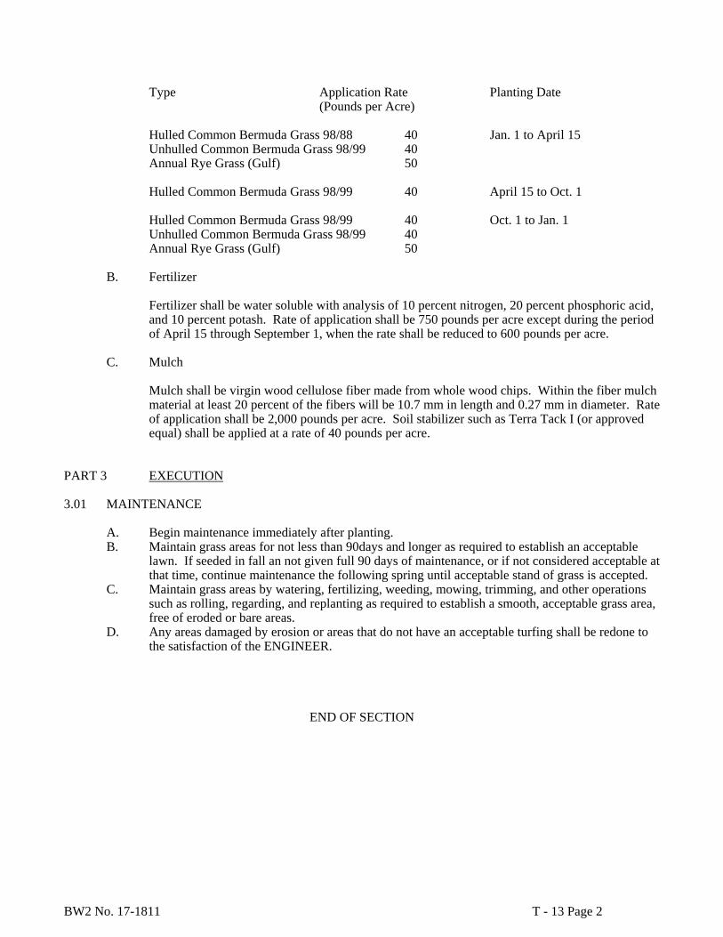
BW2 No. 17-1811 T - 13 Page 2
Type Application Rate Planting Date (Pounds per Acre) Hulled Common Bermuda Grass 98/88 40 Jan. 1 to April 15 Unhulled Common Bermuda Grass 98/99 40 Annual Rye Grass (Gulf) 50 Hulled Common Bermuda Grass 98/99 40 April 15 to Oct. 1 Hulled Common Bermuda Grass 98/99 40 Oct. 1 to Jan. 1 Unhulled Common Bermuda Grass 98/99 40 Annual Rye Grass (Gulf) 50
B. Fertilizer Fertilizer shall be water soluble with analysis of 10 percent nitrogen, 20 percent phosphoric acid, and 10 percent potash. Rate of application shall be 750 pounds per acre except during the period of April 15 through September 1, when the rate shall be reduced to 600 pounds per acre.
C. Mulch Mulch shall be virgin wood cellulose fiber made from whole wood chips. Within the fiber mulch material at least 20 percent of the fibers will be 10.7 mm in length and 0.27 mm in diameter. Rate of application shall be 2,000 pounds per acre. Soil stabilizer such as Terra Tack I (or approved equal) shall be applied at a rate of 40 pounds per acre.
PART 3 EXECUTION 3.01 MAINTENANCE
A. Begin maintenance immediately after planting. B. Maintain grass areas for not less than 90days and longer as required to establish an acceptable
lawn. If seeded in fall an not given full 90 days of maintenance, or if not considered acceptable at that time, continue maintenance the following spring until acceptable stand of grass is accepted.
C. Maintain grass areas by watering, fertilizing, weeding, mowing, trimming, and other operations such as rolling, regarding, and replanting as required to establish a smooth, acceptable grass area, free of eroded or bare areas.
D. Any areas damaged by erosion or areas that do not have an acceptable turfing shall be redone to the satisfaction of the ENGINEER.
END OF SECTION

BW2 No. 17-1811 T - 14 Page 1
SECTION T – 14
DISINFECTION OF POTABLE WATER FACILITIES PART 1 GENERAL 1.01 SCOPE OF WORK
Furnish all labor, materials, tools, equipment, and related items required to properly and completely disinfect all pipelines, structures and other facilities which are or will be in contact with potable water.
1.02 QUALIFICATIONS
All disinfecting materials shall be supplied by a single manufacturer who is fully experienced, reputable and qualified in the manufacture of the materials to be furnished.
1.03 SUBMITTALS
Submittals shall include data on disinfection material.
PART 2 PRODUCTS 2.01 MATERIALS
A. All materials to be used to disinfect the potable water pipelines, structures and facilities shall be either liquid chorine conforming to AWWA B301 or high-test calcium hypochlorite solution conforming to AWWA B300.
B. The use of chlorinated lime (bleaching powder) will not be permitted.
2.02 WATER SOURCE
The Contractor shall provide water for flushing and disinfection purposes. Water supplied for disinfection procedures shall meet all Texas State Department of Health requirements for public water supplies. It shall be the responsibility of the Contractor to provide all equipment required to transport the water from its source to the facilities to be disinfected in conformance with all laws and regulations governing transportation of potable water.
PART 3 EXECUTION 3.01 GENERAL
A. All pipelines and other facilities shall be cleaned and disinfected in conformance with all applicable sections of AWWA C601 and these specifications.
B. All waste water and disinfecting solutions shall be disposed of at Contractor’s expense in a
manner acceptable to Owner and in conformance with all applicable laws and ordinances.
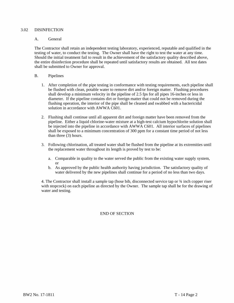
BW2 No. 17-1811 T - 14 Page 2
3.02 DISINFECTION
A. General The Contractor shall retain an independent testing laboratory, experienced, reputable and qualified in the testing of water, to conduct the testing. The Owner shall have the right to test the water at any time. Should the initial treatment fail to result in the achievement of the satisfactory quality described above, the entire disinfection procedure shall be repeated until satisfactory results are obtained. All test dates shall be submitted to Owner for approval. B. Pipelines
1. After completion of the pipe testing in conformance with testing requirements, each pipeline shall be flushed with clean, potable water to remove dirt and/or foreign matter. Flushing procedures shall develop a minimum velocity in the pipeline of 2.5 fps for all pipes 16-inches or less in diameter. If the pipeline contains dirt or foreign matter that could not be removed during the flushing operation, the interior of the pipe shall be cleaned and swabbed with a bactericidal solution in accordance with AWWA C601.
2. Flushing shall continue until all apparent dirt and foreign matter have been removed from the
pipeline. Either a liquid chlorine-water mixture at a high-test calcium hypochlorite solution shall be injected into the pipeline in accordance with AWWA C601. All interior surfaces of pipelines shall be exposed to a minimum concentration of 300 ppm for a constant time period of not less than three (3) hours.
3. Following chlorination, all treated water shall be flushed from the pipeline at its extremities until
the replacement water throughout its length is proved by test to be:
a. Comparable in quality to the water served the public from the existing water supply system, or
b. As approved by the public health authority having jurisdiction. The satisfactory quality of water delivered by the new pipelines shall continue for a period of no less than two days.
4. The Contractor shall install a sample tap (hose bib, disconnected service tap or ¾ inch copper riser with stopcock) on each pipeline as directed by the Owner. The sample tap shall be for the drawing of water and testing.
END OF SECTION
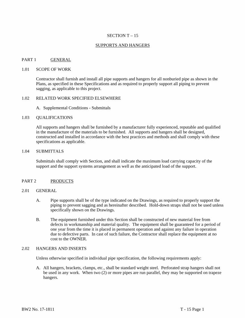
BW2 No. 17-1811 T - 15 Page 1
SECTION T – 15
SUPPORTS AND HANGERS PART 1 GENERAL 1.01 SCOPE OF WORK
Contractor shall furnish and install all pipe supports and hangers for all nonburied pipe as shown in the Plans, as specified in these Specifications and as required to properly support all piping to prevent sagging, as applicable to this project.
1.02 RELATED WORK SPECIFIED ELSEWHERE
A. Supplemental Conditions - Submittals
1.03 QUALIFICATIONS All supports and hangers shall be furnished by a manufacturer fully experienced, reputable and qualified in the manufacture of the materials to be furnished. All supports and hangers shall be designed, constructed and installed in accordance with the best practices and methods and shall comply with these specifications as applicable.
1.04 SUBMITTALS
Submittals shall comply with Section, and shall indicate the maximum load carrying capacity of the support and the support systems arrangement as well as the anticipated load of the support.
PART 2 PRODUCTS 2.01 GENERAL
A. Pipe supports shall be of the type indicated on the Drawings, as required to properly support the piping to prevent sagging and as hereinafter described. Hold-down straps shall not be used unless specifically shown on the Drawings.
B. The equipment furnished under this Section shall be constructed of new material free from
defects in workmanship and material quality. The equipment shall be guaranteed for a period of one year from the time it is placed in permanent operation and against any failure in operation due to defective parts. In cast of such failure, the Contractor shall replace the equipment at no cost to the OWNER.
2.02 HANGERS AND INSERTS
Unless otherwise specified in individual pipe specification, the following requirements apply:
A. All hangers, brackets, clamps, etc., shall be standard weight steel. Perforated strap hangers shall not be used in any work. When two (2) or more pipes are run parallel, they may be supported on trapeze hangers.
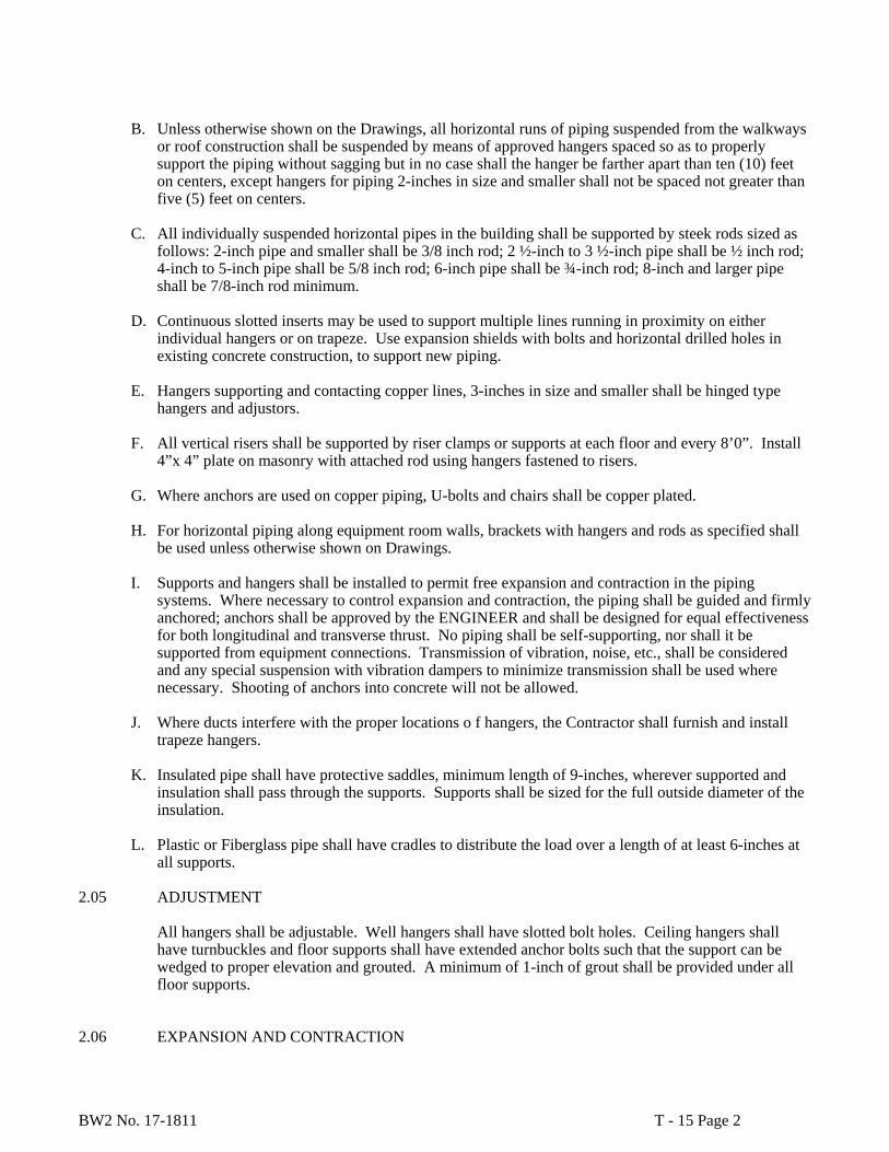
BW2 No. 17-1811 T - 15 Page 2
B. Unless otherwise shown on the Drawings, all horizontal runs of piping suspended from the walkways or roof construction shall be suspended by means of approved hangers spaced so as to properly support the piping without sagging but in no case shall the hanger be farther apart than ten (10) feet on centers, except hangers for piping 2-inches in size and smaller shall not be spaced not greater than five (5) feet on centers.
C. All individually suspended horizontal pipes in the building shall be supported by steek rods sized as
follows: 2-inch pipe and smaller shall be 3/8 inch rod; 2 ½-inch to 3 ½-inch pipe shall be ½ inch rod; 4-inch to 5-inch pipe shall be 5/8 inch rod; 6-inch pipe shall be ¾-inch rod; 8-inch and larger pipe shall be 7/8-inch rod minimum.
D. Continuous slotted inserts may be used to support multiple lines running in proximity on either
individual hangers or on trapeze. Use expansion shields with bolts and horizontal drilled holes in existing concrete construction, to support new piping.
E. Hangers supporting and contacting copper lines, 3-inches in size and smaller shall be hinged type
hangers and adjustors.
F. All vertical risers shall be supported by riser clamps or supports at each floor and every 8’0”. Install 4”x 4” plate on masonry with attached rod using hangers fastened to risers.
G. Where anchors are used on copper piping, U-bolts and chairs shall be copper plated.
H. For horizontal piping along equipment room walls, brackets with hangers and rods as specified shall
be used unless otherwise shown on Drawings.
I. Supports and hangers shall be installed to permit free expansion and contraction in the piping systems. Where necessary to control expansion and contraction, the piping shall be guided and firmly anchored; anchors shall be approved by the ENGINEER and shall be designed for equal effectiveness for both longitudinal and transverse thrust. No piping shall be self-supporting, nor shall it be supported from equipment connections. Transmission of vibration, noise, etc., shall be considered and any special suspension with vibration dampers to minimize transmission shall be used where necessary. Shooting of anchors into concrete will not be allowed.
J. Where ducts interfere with the proper locations o f hangers, the Contractor shall furnish and install
trapeze hangers.
K. Insulated pipe shall have protective saddles, minimum length of 9-inches, wherever supported and insulation shall pass through the supports. Supports shall be sized for the full outside diameter of the insulation.
L. Plastic or Fiberglass pipe shall have cradles to distribute the load over a length of at least 6-inches at
all supports. 2.05 ADJUSTMENT
All hangers shall be adjustable. Well hangers shall have slotted bolt holes. Ceiling hangers shall have turnbuckles and floor supports shall have extended anchor bolts such that the support can be wedged to proper elevation and grouted. A minimum of 1-inch of grout shall be provided under all floor supports.
2.06 EXPANSION AND CONTRACTION
BW2 No. 17-1811 T - 15 Page 3
Supports midway between expansion joints shall be rigid clamps allowing no vertical or horizontal movement. All other supports in lines with expansion joints shall be of the roller type with the roller contoured to the pipe outside dimension. Where the pipe is insulated, the roller type support shall be contoured to the insulation and protective saddle.
2.07 PIPE RACK
Pipe is supported on pipe rack shall be supported on channels manufactured by Unistrut, Powerstrut or equal. The pipes shall be clamped on the channel support by pipe clamps of the same manufacturer.
PART 3 EXECUTION 3.01 INSTALLATION
Pipe installation shall be such that all supports share the pipe load. Vertical adjustments shall be made as required. Supports shall be installed in perfect alignment such that no binding of pipe takes place. All supports shall be field painted in accordance with Section, Mechanical Painting.
END OF SECTION

BW2 No. 17-1811 T - 16 Page 1
SECTION T - 16
TESTING OF PIPELINES PART 1 GENERAL 1.01 SCOPE OF WORK
Furnish all labor, materials, tools, equipment, and related items required to perform exfiltration tests of gravity pipelines and to perform integrity and leakage tests of pressurized pipelines.
1.02 SUBMITTALS
Submittals shall include a description of the testing procedures to be employed for testing and the report form to be employed.
PART 2 PRODUCTS 2.01 WATER FOR TESTING
The Contractor shall provide the necessary water required for testing the work. PART 3 EXECUTION 3.01 GENERAL
A. The entire length of all pressurized pipelines shall be field tested for tightness by a test as described hereinafter.
B. The Contractor shall furnish all labor and equipment, including required pumps with regulated
bypass meters and gauges, for conducting of the pipeline tests.
C. The Contractor shall furnish all equipment, necessary piping and required labor to transport water form its source to the test location for use in testing.
D. The timing and sequence of testing shall be scheduled by the Contractor, subject to the approval
of the Owner. The Contractor shall provide the Owner with a minimum of two (2) hours notice prior to the start of any test. All tests must be observed by the Owner.
E. The Contractor shall repair any leaks discovered during the initial filling of the pipeline and
during the testing phase. All known and visible leaks shall be replaced whether or not the leakage rate is within allowable limits.
3.02 TEST PROCEDURES FOR PRESSURE PIPELINES
A. General
1. All pipelines shall be pressure tested in accordance with the specifications following for each type of service.
BW2 No. 17-1811 T - 16 Page 2
2. All meters, fixtures, devices or appliances are connected to the pipeline system and which might be damaged if subjected to the specified test pressure shall be disconnected and the ends of the branch lines plugged or capped during the test procedures. Stems which are damaged during the testing procedure shall be repaired or replaced by the Contractor at no expense to the Owner.
3. Where any section of a pipeline is provided with concrete reaction blocking, the pressure test
shall not be made until at least five (5) days have elapsed after the installation of the blocking. B. Pressure Pipelines
1. All pipelines scheduled to carry water or water-chemical solution mixtures shall be hydrostatically pressure tested.
2. All pipelines shall be segmented by capping, plugging or closing of valves. Each section of
piping shall be pumped full of water, and all air shall be removed to a pressure no less than two times (2x) the maximum anticipated operating head or 150 psi, whichever is greater. The pump shall contain adequate gauges to indicate the internal pipe pressure during the test.
3. The test shall be conducted for a period of four (4) hours during which the pressure shall be
maintained within 5 psi of the specified test pressure. All water added to the system shall be accurately measured to ascertain the exact quantity lost during the test.
4. Allowable leakage in steel pipes shall be zero, except gate valves shall be permitted a maximum
leakage rate of one (1) ounce per hour per inch of nominal valve size, in conformance with AWWA C500.
5. Allowable leakage in cast iron and ductile iron pipe shall be in conformance with AWWA C600,
Section 4.2 and Table 6.
6. Allowable leakage in PVC pipe shall be 11.65 gallons per inch of nominal diameter of pipe per mile over a 24 hour period.
3.03 FINAL ACCEPTANCE
A. No pipeline installation shall be accepted until all known and visible leaks have been repaired, whether or not the leakage is within the maximum allowable limits. The locating and repairing of leaks shall be performed by the Contractor at no additional expense to the Owner.
B. The Owner will certify that all required tests have been successfully completed before the pipeline is
accepted.
END OF SECTION

BW2 No. 17-1811 T - 17 Page 1
SECTION T-17
ENGINE GENERATORS
Part 1 GENERAL
The contractor shall provide for a factory representative to perform a full load test on site after installation is complete to prove the unit will perform to all specified parameters. The test shall be witnessed by the Owners representative. The Contractor shall provide a “Load Bank”, cabling and all other appurtenances necessary to conduct the test.
A. The system shall include a remote status and control panel located in the Fire Command Center. This system is in addition to the unit mounted status and control equipment.
B. Weather Proof Enclosure.
C. Natural gas fuel supply, valve train, and pressure regulators.
D. Residential grade muffler.
E. Concrete base 8” above grade – provide signed & sealed engineered foundation drawings.
F. Output circuit breaker.
G. Transfer switch.
1.2 SCOPE
A. Provide complete factory assembled natural gas generator set equipment with digital
(microprocessor-based) electronic generator set controls, digital governor, and digital voltage regulator.
B. Provide factory test, startup by a supplier authorized by the equipment manufacturer(s), and on-site testing of the system.
C. The generator set manufacturer shall warrant all equipment provided under this section so that there is one source for warranty and product service. Technicians specifically trained and certified by the manufacturer to support the product and employed by the generator set supplier shall service the generator sets.
1.3 CODES AND STANDARDS
A. The generator set installation and on-site testing shall conform to the requirements of the
following codes and standards, as applicable. The generator set shall include necessary features to meet the requirements of these standards.

BW2 No. 17-1811 T - 17 Page 2
1. CSA 282, 1989 Emergency Electrical Power Supply for Buildings
2. IEEE446 – Recommended Practice for Emergency and Standby Power Systems for Commercial and Industrial Applications
3. NFPA37
4. NFPA70 – National Electrical Code. Equipment shall be suitable for use in systems in compliance to Article 700, 701, and 702.
5. NFPA99 – Essential Electrical Systems for Health Care Facilities
6. NFPA110 – Emergency and Standby Power Systems. The generator set shall meet all requirements for Level 1 systems. Level 1prototype tests required by this standard shall have been performed on a complete and functional unit, component level type tests will not substitute for this requirement.
B. The generator set and supplied accessories shall meet the requirements of the following standards:
1. NEMA MG1. Alternator shall comply with the requirements of the current version this standard as they apply to AC alternators.
2. UL1236 – Battery Chargers
3. UL2200. The generator set shall be listed to UL2200 or submit to an independent third party certification process to verify compliance as installed..
C. The control system for the generator set shall comply with the following requirements.
1. CSA C22.2, No. 14 – M91 Industrial Control Equipment.
2. EN50082-2, Electromagnetic Compatibility – Generic Immunity Requirements, Part 2: Industrial.
3. EN55011, Limits and Methods of Measurement of Radio Interference Characteristics of Industrial, Scientific and Medical Equipment.
4. FCC Part 15, Subpart B.
5. IEC8528 part 4. Control Systems for Generator Sets
6. IEC Std 801.2, 801.3, and 801.5 for susceptibility, conducted, and radiated electromagnetic emissions.
7. UL508. The entire control system of the generator set shall be UL508 listed and labeled.
8. UL1236 –Battery Chargers.
D. The generator set manufacturer shall be certified to ISO 9001 International Quality Standard and shall have third party certification verifying quality assurance in design/development, production, installation, and service, in accordance with ISO 9001.
BW2 No. 17-1811 T - 17 Page 3
1.4 ACCEPTABLE MANUFACTURERS
A. Cummins Power Generation
B. Caterpillar
C. Onan
D. Detroit Diesel
Only approved bidders shall supply equipment provided under this contract. Equipment specifications for this project are based on generator sets manufactured by Cummins Power Generation with microprocessor-based controls. Proposals of alternate manufacturers must include a line by line compliance statement based on this specification.
PART 2 PRODUCTS
1.02 GENERATOR SET
A. Ratings
1. The generator set shall operate at 1800 rpm and at a voltage of: 277/480 Volts AC, Three phase, 4-wire, 60 hertz.
2. Refer to the plans for the kW rating of the generator set, rated at 0.8 PF, standby rating, based on site conditions of : Altitude 1000 ft., ambient temperatures up to 122 degrees F.
3. The generator set rating shall be based on emergency/standby service.
B. Performance
1. Voltage regulation shall be plus or minus 0.5 percent for any constant load between no load and rated load. Random voltage variation with any steady load from no load to full load shall not exceed plus or minus 0.5 percent.
2. Frequency regulation shall be isochronous from steady state no load to steady state rated load. Random frequency variation with any steady load from no load to full load shall not exceed plus or minus 0.5%.
3. The natural gas engine-generator set shall accept a single step load of 100% nameplate kW and power factor, less applicable derating factors, with the engine-generator set at operating temperature.
4. Motor starting capability shall be a minimum of 4602 kVA. The generator set shall be capable of recovering to a minimum of 90% of rated no load voltage following the application of the specified kVA load at near zero power factor applied to the generator set. Maximum voltage dip on application of this load, considering both alternator performance and engine speed changes shall not exceed 25%.

BW2 No. 17-1811 T - 17 Page 4
5. The alternator shall produce a clean AC voltage waveform, with not more than 5% total harmonic distortion at full linear load, when measured from line to neutral, and with not more than 3% in any single harmonic, and no 3rd order harmonics or their multiples. Telephone influence factor shall be less than 40.
6. The generator set shall be certified by the engine manufacturer to be suitable for use at the installed location and rating, and shall meet all applicable exhaust emission requirements at the time of commissioning.
C. Construction
1. The engine-generator set shall be mounted on a heavy-duty steel base to maintain alignment between components. The base shall incorporate a battery tray with hold-down clamps within the rails.
2. All switches, lamps, and meters in the control system shall be oil-tight and dust-tight. All active control components shall be installed within a UL/NEMA 3R enclosure. There shall be no exposed points in the control (with the door open) that operate in excess of 50 volts.
D. Connections
1. The generator set load connections shall be composed of silver or tin plated copper bus bars, drilled to accept mechanical or compression terminations of the number and type as shown on the drawings. Sufficient lug space shall be provided for use with cables of the number and size as shown on the drawings.
2. Power connections to auxiliary devices shall be made at the devices, with required protection located at a wall-mounted common distribution panel.
3. Generator set control interfaces to other system components shall be made on a permanently labeled terminal block assembly. Labels describing connection point functions shall be provided.
1.03 ENGINE AND ENGINE EQUIPMENT
The engine shall be natural gas, 2 cycle, radiator and fan cooled. The horsepower rating of the engine at its minimum tolerance level shall be sufficient to drive the alternator and all connected accessories. Engine accessories and features shall include: A. An electronic governor system shall provide automatic isochronous frequency regulation. The
governing system dynamic capabilities shall be controlled as a function of engine coolant temperature to provide fast, stable operation at varying engine operating temperature conditions. The control system shall actively control the fuel rate and excitation as appropriate to the state of the generator set. Fuel rate shall be regulated as a function of starting, accelerating to start disconnect speed, accelerating to rated speed. The governing system shall include a programmable warm up at idle and cooldown at idle function. While operating in idle state, the control system shall disable the alternator excitation system.
BW2 No. 17-1811 T - 17 Page 5
B. Skid-mounted radiator and cooling system rated for full load operation in 122 degrees F (50 degrees C) ambient as measured at the alternator air inlet. Radiator fan shall be suitable for use in a system with 0.5 in H2O restriction. Radiator shall be sized based on a core temperature that is 20F higher than the rated operation temperature, or prototype tested to verify cooling performance of the engine/radiator/fan operation in a controlled environment. Radiator shall be provided with a duct adapter flange. The equipment manufacturer shall fill the cooling system with a 50/50-ethylene glycol/water mixture prior to shipping. Rotating parts shall be guarded against accidental contact.
C. Electric starter(s) capable of three complete cranking cycles without overheating.
D. Positive displacement, mechanical, full pressure, lubrication oil pump.
E. Full flow lubrication oil filters with replaceable spin-on canister elements and dipstick oil level indicator.
F. Replaceable dry element air cleaner with restriction indicator.
G. Flexible supply lines.
H. Engine mounted battery charging alternator, 40-ampere minimum, and solid-state voltage regulator.
I. Coolant heater
1. Engine mounted, thermostatically controlled, coolant heater(s) for each engine. Heater voltage shall be as shown on the project drawings. The coolant heater shall be UL499 listed and labeled.
2. The coolant heater shall be installed on the engine with silicone hose connections. Steel tubing shall be used for connections into the engine coolant system wherever the length of pipe run exceeds 12 inches. The coolant heater installation shall be specifically designed to provide proper venting of the system. The coolant heaters shall provisions to isolate the heater for replacement of the heater element without draining the coolant from the generator set. The quick disconnect/automatic sealing couplers shall allow the heater element to be replaced without draining the engine cooling system or significant coolant loss.
3. The coolant heater shall be provided with a DC thermostat, installed at the engine thermostat housing. An AC power connection box shall be provided for a single AC power connection to the coolant heater system.
4. The coolant heater(s) shall be sized as recommended by the engine manufacturer to warm the engine to a minimum of 104F (40C) in a 40F (4C) ambient, in compliance with NFPA110 requirements, or the temperature required for starting and load pickup requirements of this specification.
J. Provide vibration isolators,type, quantity as recommended by the generator set manufacturer. Isolators shall include seismic restraints if required by site location.
K. Starting and Control Batteries shall be calcium/lead antimony type, 24 volt DC, sized as recommended by the engine manufacturer, complete with battery cables and connectors. The batteries shall be capable of a minimum of three complete 15-second cranking cycles at 40F ambient temperature when fully charged.

BW2 No. 17-1811 T - 17 Page 6
L. Provide exhaust silencer(s) for each engine of size and type as recommended by the generator set manufacturer and approved by the engine manufacturer. The mufflers shall be critical grade. Exhaust system shall be installed according to the engine manufacturer’s recommendations and applicable codes and standards. Provide a minimum 10 amp battery charger for each generator set battery bank. The charger(s) shall include the following capabilities:
1. Chargers shall be UL 1236-BBHH listed and CSA or CUL certified for use in emergency applications.
2. The charger shall be compliant with UL991 requirements for vibration resistance.
3. The charger shall comply with the requirements of EN61000-4-5 for voltage surge resistance; EN50082-2 for immunity; EN61000-4-2 for ESD; EN61000-4-3 for radiated immunity; ANSI/IEEE C62.41 category B and IN61000-4-4 for electrically fast transient; EN61000-4-6 for conducted emissions; and FCC Part 15 Class A for radiated emissions.
4. The charger shall be capable of charging a fully discharged battery without damage to the charger. It shall be capable of returning a fully discharged battery to fully charged condition within 24 hours. The charger shall be UL-labeled with the maximum battery amp-hour rating that can be recharged within 24 hours. The label shall indicate that the charger is suitable for charging of 200AH batteries per NFPA requirements.
5. The charger shall incorporate a 4-state charging algorithm, to provide trickle charge rate to restore fully discharged batteries, a bulk charge rate to provide fastest possible recharge after normal discharge, an absorption state to return the battery to 100 percent of charge, and a float stage to maintain a fully charge battery and supply battery loads when the generator set is not operating. In addition, the charger shall include an equalization timer. Charge rates shall be temperature compensated based on the temperature directly sensed at the battery.
6. The DC output voltage regulation shall be within plus or minus 1%. The DC output ripple current shall not exceed 1 amp at rated output current level.
7. The charger shall include the following features:
a) two line alphanumeric display with programming keys to allow display of DC output ammeter and voltmeters (5% accuracy or better), display alarm messages, and perform programming;
b) LED indicating lamp(s) to indicating normal charging condition (green), equalize charge state (amber), and fault condition (red);
c) AC input overcurrent, over voltage, and undervoltage protection; d) DC output overcurrent protection; e) Alarm output relay f) Corrosion resistant aluminum enclosure
1.04 AC GENERATOR
A. The AC generator shall be; synchronous, four pole, 2/3 pitch, revolving field, drip-proof
construction, single prelubricated sealed bearing, air cooled by a direct drive centrifugal blower fan, and directly connected to the engine with flexible drive disc. All insulation system components shall meet NEMA MG1 temperature limits for Class H insulation system and shall
BW2 No. 17-1811 T - 17 Page 7
be UL1446 listed. Actual temperature rise measured by resistance method at full load shall not exceed 105 degrees Centigrade.
B. The generator shall be capable of delivering rated output (kVA) at rated frequency and power factor, at any voltage not more than 5 percent above or below rated voltage.
C. A permanent magnet generator (PMG) shall be included to provide a reliable source of excitation power for optimum motor starting and short circuit performance. The PMG and controls shall be capable of sustaining and regulating current supplied to a single phase or three phase fault at approximately 300% of rated current for not more than 10 seconds.
D. The subtransient reactance of the alternator shall not exceed 15 percent, based on the standby rating of the generator set.
1.05 GENERATOR SET CONTROL.
The generator set shall be provided with a microprocessor-based control system that is designed to provide automatic starting, monitoring, and control functions for the generator set. The control system shall also be designed to allow local monitoring and control of the generator set, and remote monitoring and control as described in this specification.
The control shall be mounted on the generator set, or may be mounted in a free-standing panel next to the generator set if adequate space and accessibility is available. The control shall be vibration isolated and prototype tested to verify the durability of all components in the system under the vibration conditions encountered.
The generator set mounted control shall include the following features and functions:
A. Control Switches
1. Mode Select Switch. The mode select switch shall initiate the following control modes. When in the RUN or MANUAL position the generator set shall start, and accelerate to rated speed and voltage as directed by the operator. A separate push-button to initiate starting is acceptable. In the OFF position the generator set shall immediately stop, bypassing all time delays. In the AUTO position the generator set shall be ready to accept a signal from a remote device to start and accelerate to rated speed and voltage.
2. EMERGENCY STOP switch. Switch shall be Red "mushroom-head" push-button. Depressing the emergency stop switch shall cause the generator set to immediately shut down, and be locked out from automatic restarting.
3. RESET switch. The RESET switch shall be used to clear a fault and allow restarting the generator set after it has shut down for any fault condition.
4. PANEL LAMP switch. Depressing the panel lamp switch shall cause the entire panel to be lighted with DC control power. The panel lamps shall automatically be switched off 10 minutes after the switch is depressed, or after the switch is depressed a second time.
B. Generator Set AC Output Metering. The generator set shall be provided with a metering set including the following features and functions:

BW2 No. 17-1811 T - 17 Page 8
1. Digital metering set, 1% accuracy, to indicate generator RMS voltage and current, frequency, output current, output KW, KW-hours, and power factor. Generator output voltage shall be available in line-to-line and line-to-neutral voltages, and shall display all three-phase voltages (line to neutral or line to line) simultaneously.
2. Analog voltmeter, ammeter, frequency meter, power factor meter, and kilowatt (KW) meter. Voltmeter and ammeter shall display all three phases. Meter scales shall be color coded in the following fashion: green shall indicate normal operating condition, amber shall indicate operation in ranges that indicate potential failure, and red shall indicate failure impending. Metering accuracy shall be within 1% at rated output. Both analog and digital metering are required.
3. The control system shall monitor the total load on the generator set, and maintain data logs of total operating hours at specific load levels ranging from 0 to 110% of rated load, in 10% increments. The control shall display hours of operation at less than 30% load and total hours of operation at more than 90% of rated load.
4. The control system shall log total number of operating hours, total kWH, and total control on hours, as well as total values since reset.
C. Generator Set Alarm and Status Display.
1. The generator set control shall include LED alarm and status indication lamps. The lamps shall be high-intensity LED type. The lamp condition shall be clearly apparent under bright room lighting conditions. Functions indicated by the lamps shall include:
The control shall include five configurable alarm-indicating lamps. The lamps shall be field adjustable for any status, warning, or shutdown function monitored by the genset. They shall also be configurable for color, and control action (status, warning, or shutdown).
The control shall include green lamps to indicate that the generator set is running at rated frequency and voltage, and that a remote start signal has been received at the generator set. The running signal shall be based on actual sensed voltage and frequency on the output terminals of the generator set.
The control shall include a flashing red lamp to indicate that the control is not in automatic state, and red common shutdown lamp.
The control shall include an amber common warning indication lamp.
2. The generator set control shall indicate the existence of the warning and shutdown conditions on the control panel. All conditions indicated below for warning shall be field-configurable for shutdown. Conditions required to be annunciated shall include:
low oil pressure (warning) low oil pressure (shutdown) oil pressure sender failure (warning) low coolant temperature (warning) high coolant temperature (warning) high coolant temperature (shutdown) high oil temperature (warning) engine temperature sender failure (warning) low coolant level (warning) fail to crank (shutdown)

BW2 No. 17-1811 T - 17 Page 9
fail to start/overcrank (shutdown) overspeed (shutdown) low DC voltage (warning) high DC voltage (warning) weak battery (warning) low fuel-daytank (warning) high AC voltage (shutdown) low AC voltage (shutdown) under frequency (shutdown) over current (warning) over current (shutdown) short circuit (shutdown) over load (warning) emergency stop (shutdown) (4) configurable conditions
3. Provisions shall be made for indication of four customer-specified alarm or shutdown conditions. Labeling of the customer-specified alarm or shutdown conditions shall be of the same type and quality as the above-specified conditions. The non-automatic indicating lamp shall be red, and shall flash to indicate that the generator set is not able to automatically respond to a command to start from a remote location.
D. Engine Status Monitoring.
1. The following information shall be available from a digital status panel on the generator set control :
engine oil pressure (psi or kPA) engine coolant temperature (degrees F or C) engine oil temperature (degrees F or C) engine speed (rpm) number of hours of operation (hours) number of start attempts battery voltage (DC volts)
2. The control system shall also incorporate a data logging and display provision to allow logging of the last 10 warning or shutdown indications on the generator set, as well as total time of
3. operation at various loads, as a percent of the standby rating of the generator set.
E. Engine Control Functions.
1. The control system provided shall include a cycle cranking system, which allows for user selected crank time, rest time, and # of cycles. Initial settings shall be for 3 cranking periods of 15 seconds each, with 15-second rest period between cranking periods.
BW2 No. 17-1811 T - 17 Page 10
2. The control system shall include an idle mode control, which allows the engine to run in idle mode in the RUN position only. In this mode, the alternator excitation system shall be disabled.
3. The control system shall include an engine governor control, which functions to provide steady state frequency regulation as noted elsewhere in this specification. The governor control shall include adjustments for gain, damping, and a ramping function to control engine speed and limit exhaust smoke while the unit is starting.
4. The control system shall include time delay start (adjustable 0-300 seconds) and time delay stop (adjustable 0-600 seconds) functions.
5. The control system shall include sender failure monitoring logic for speed sensing, oil pressure, and engine temperature which is capable of discriminating between failed sender or wiring components, and an actual failure conditions.
F. Alternator Control Functions:
1. The generator set shall include a full wave rectified automatic digital voltage regulation system that is matched and prototype tested by the engine manufacturer with the governing system provided. It shall be immune from misoperation due to load-induced voltage waveform distortion and provide a pulse width modulated output to the alternator exciter. The voltage regulation system shall be equipped with three-phase line to neutral RMS sensing and shall control buildup of AC generator voltage to provide a linear rise and limit overshoot. The system shall include a torque-matching characteristic, which shall reduce output voltage in proportion to frequency below an adjustable frequency threshold. Torque matching characteristic shall be adjustable for roll-off frequency and rate, and be capable of being curve-matched to the engine torque curve with adjustments in the field. The voltage regulator shall include adjustments for gain, damping, and frequency roll-off. Adjustments shall be broad range, and made via digital raise-lower switches, with an alphanumeric LED readout to indicate setting level. Rotary potentiometers for system adjustments are not acceptable.
2. A microprocessor-based protection device shall be provided to individually monitor all phases of the output current of the generator set and initiate an alarm (over current warning) when load current exceeds 110% of the rated current of the generator set on any phase for more than 60 seconds. The device shall shut down and lock out the generator set when output current level approaches the thermal damage point of the alternator (over current shutdown). The protective functions provided shall be in compliance to the requirements of NFPA70 article 445.
3. A microprocessor-based protection device shall be provided to monitor all phases of the output current for short circuit conditions. The control/protection system shall monitor the current level and voltage. The controls shall shut down and lock out the generator set when output current level approaches the thermal damage point of the alternator (short circuit shutdown). The protective functions provided shall be in compliance to the requirements of NFPA70 article 445.
4. Controls shall be provided to monitor the KW load on the generator set, and initiate an alarm condition (over load) when total load on the generator set exceeds the generator set rating for in excess of 5 seconds. Controls shall include a load shed control, to operate a set of dry contacts (for use in shedding customer load devices) when the generator set is overloaded.
BW2 No. 17-1811 T - 17 Page 11
A microprocessor-based AC over/under voltage monitoring system that responds only to true RMS voltage conditions shall be provided. The system shall initiate shutdown of the generator set when alternator output voltage exceeds 110% of the operator-set voltage level for more than 10 seconds, or with no intentional delay when voltage exceeds 130%. Under voltage shutdown shall occur when the output voltage of the alternator is less than 85% for more than 10 seconds. The system shall monitor individual phases and be connected line to neutral on 3-phase 4-wire generator sets, and for systems that are solidly grounded.

BW2 No. 17-1811 T - 17 Page 12
G. Other Control Functions
1. A battery monitoring system shall be provided which initiates alarms when the DC control and starting voltage is less than 25VDC or more than 32 VDC. During engine cranking (starter engaged), the low voltage limit shall be disabled, and DC voltage shall be monitored as load is applied to the battery, to detect impending battery failure or deteriorated battery condition.
H. Control Interfaces for Remote Monitoring:
1. The control system shall provide four programmable output relays. These relay outputs shall be configurable for any alarm, shutdown, or status condition monitored by the control. The relays shall be configured to indicate: (1) generator set operating at rated voltage and frequency, (2) common warning, (3) common shutdown, (4) load shed command.
2. A fused 10 amp switched 24VDC power supply circuit shall be provided for customer use. DC power shall be available from this circuit whenever the generator set is running.
3. A fused 10 amp 24VDC power supply circuit shall be provided for customer use. DC power shall be available from this circuit at all times from the engine starting/control batteries.
4. The control shall be provided with a direct serial communication link for the LonWorks communication network interface as described elsewhere in this specification and shown on the drawings.
1.06 OTHER EQUIPMENT TO BE PROVIDED WITH THE GENERATOR SET
A. Provide and install a 20-light LED type remote alarm annunciator with horn, located as shown on the drawings or in a location that can be conveniently monitored by facility personnel. The remote annunciator shall provide all the audible and visual alarms called for by NFPA Standard 110 for level 1 systems for the local generator control panel. Spare lamps shall be provided to allow future addition of other alarm and status functions to the annunciator. Provisions for labeling of the annunciator in a fashion consistent with the specified functions shall be provided. Alarm silence and lamp test switch(es) shall be provided. LED lamps shall be replaceable, and indicating lamp color shall be capable of changes needed for specific application requirements. Alarm horn shall be switchable for all annunciation points. Alarm horn (when switched on) shall sound for first fault, and all subsequent faults, regardless of whether first fault has been cleared, in compliance with NFPA110 3-5.6.2. The interconnecting wiring between the annunciator and other system components shall be monitored and failure of the interconnection between components shall be displayed on the annunciator panel.
B. The annunciator shall include the following alarm labels, audible annunciation features, and lamp colors:
Condition Lamp Color Audible Alarm
Normal Power (to Loads) Green No Genset Supplying Load Amber No Genset Running Green No Not in Auto Red
(Flashing) Yes

BW2 No. 17-1811 T - 17 Page 13
High Battery Voltage Red Yes Low Battery Voltage Red Yes Charger AC Failure Red Yes Fail to Start Red Yes Low Engine Temperature Amber Yes Pre-High Engine Temperature Amber Yes High Engine Temperature Red Yes Pre-Low Oil Pressure Amber Yes Low Oil Pressure Red Yes Overspeed Red Yes Low Coolant Level Amber Yes Low Fuel Level Amber Yes Network OK Green Yes (4) Spares Configurable Configurable
Low battery voltage lamp shall also be lighted for low cranking voltage or weak battery alarm.
C. The generator set shall be provided with a mounted main line circuit breaker, sized to carry the rated output current of the generator set. The circuit breaker shall incorporate an electronic trip unit that operates to protect the alternator under all overcurrent conditions, or a thermal-magnetic trip with other overcurrent protection devices that positively protect the alternator under overcurrent conditions. The supplier shall submit time overcurrent characteristic curves and thermal damage curve for the alternator, demonstrating the effectiveness of the protection provided.
D. Outdoor Weather-Protective Enclosure
1. The generator set shall be provided with an outdoor enclosure. The package shall comply with the requirements of the National Electrical Code for all wiring materials and component spacing. The total assembly of generator set, enclosure, and sub-base fuel tank (when used) shall be designed to be lifted into place using spreader bars. Housing shall provide ample airflow for generator set operation at rated load in an ambient temperature of 100F. The housing shall have hinged access doors as required to maintain easy access for all operating and service functions. All doors shall be lockable, and include retainers to hold the door open during service. Enclosure roof shall be cambered to prevent rainwater accumulation. Openings shall be screened to limit access of rodents into the enclosure. All electrical power and control interconnections shall be made within the perimeter of the enclosure.
2. All sheet metal shall be primed for corrosion protection and finish painted with the manufacturers standard color using a two step electrocoating paint process, or equal meeting the performance requirements specified below. All surfaces of all metal parts shall be primed and painted. The painting process shall result in a coating that meets the following requirements:
Primer thickness, 0.5-2.0 mils. Top coat thickness, 0.8-1.2 mils.

BW2 No. 17-1811 T - 17 Page 14
Gloss, per ASTM D523-89, 80% plus or minus 5%. Gloss retention after one year shall exceed 50%.
Crosshatch adhesion, per ASTM D3359-93, 4B-5B.
Impact resistance, per ASTM D2794-93, 120-160 inch-pounds.
Salt Spray, per ASTM B117-90, 1000+ hours.
Humidity, per ASTM D2247-92, 1000+ hours.
Water Soak, per ASTM D2247-92, 1000+ hours.
BW2 No. 17-1811 T - 17 Page 15
3. Painting of hoses, clamps, wiring harnesses, and other non-metallic service parts shall not be acceptable. Fasteners used shall be corrosion resistant, and designed to minimize marring of the painted surface when removed for normal installation or service work.
4. Enclosure shall be constructed of minimum 12 gauge steel for framework and 14 gauge steel for panels. All hardware and hinges shall be stainless steel.
5. A exhaust silencer shall be installed outside of the enclosure. The exhaust shall exit the enclosure through a rain collar and terminate with a rain cap. Exhaust connections to the generator set shall be through seamless flexible connections.
6. Manufacturer shall provide a means to connect to the existing aboveground fuel tank.
Part 2. OPERATION
2.01 SEQUENCE OF OPERATION
A. Generator set shall start on receipt of a start signal from remote equipment. The start signal shall be via hardwired connection to the generator set control.
B. The generator set shall complete a time delay start period as programmed into the control.
C. The generator set control shall initiate the starting sequence for the generator set. The starting sequence shall include the following functions:
D. The control system shall verify that the engine is rotating when the starter is signaled to operate. If the engine does not rotate after two attempts, the control system shall shut down and lock out the generator set, and indicate “fail to crank” shutdown.
E. The engine shall fire and accelerate as quickly as practical to start disconnect speed. If the engine does not start, it shall complete a cycle cranking process as described elsewhere in this specification. If the engine has not started by the completion of the cycle cranking sequence, it shall be shut down and locked out, and the control system shall indicate “fail to start”.
F. The engine shall accelerate to rated speed and the alternator to rated voltage. Excitation shall be disabled until the engine has exceeded programmed idle speed, and regulated to prevent over voltage conditions and oscillation as the engine accelerates and the alternator builds to rated voltage.
G. On reaching rated speed and voltage, the generator set shall operate as dictated by the control system in isochronous state.
H. When all start signals have been removed from the generator set, it shall complete a time delay stop sequence. The duration of the time delay stop period shall be adjustable by the operator.
I. On completion of the time delay stop period, the generator set control shall switch off the excitation system and shall shut down.
J. Any start signal received after the time stop sequence has begun shall immediately terminate the stopping sequence and return the generator set to isochronous operation.
BW2 No. 17-1811 T - 17 Page 16
Part 3. OTHER REQUIREMENTS
3.01 SUBMITTALS
A. Within 10 days after award of contract, provide six sets of the following information for review:
Manufacturer’s product literature and performance data, sufficient to verify compliance to specification requirements.
Manufacturer's certification of prototype testing. Manufacturer's published warranty documents. Shop drawings showing plan and elevation views with certified overall dimensions, as well
as wiring interconnection details. Interconnection wiring diagrams showing all external connections required; with field wiring
terminals marked in a consistent point-to-point manner. Manufacturer's installation instructions.
BW2 No. 17-1811 T - 17 Page 17
3.02 FACTORY TESTING
A. The generator set manufacturer shall perform a complete operational test on the generator set prior to shipping from the factory. A certified test report shall be provided. Equipment supplied shall be fully tested at the factory for function and performance.
B. Factory testing may be witnessed by the owner and consulting engineer. Costs for travel expenses will be the responsibility of the owner and consulting engineer. Supplier is responsible to provide two weeks notice for testing.
C. Generator set factory tests on the equipment shall be performed at rated load and rated power factor. Generator sets that have not been factory tested at rated power factor will not be acceptable. Tests shall include: 4 hour run at full load, maximum power, voltage regulation, transient and steady-state governing, single step load pickup, and function of safety shutdowns.
3.03 INSTALLATION
A. Equipment shall be installed by the contractor in accordance with final submittals and contract documents. Installation shall comply with applicable state and local codes as required by the authority having jurisdiction. Install equipment in accordance with manufacturer's instructions and instructions included in the listing or labeling of UL listed products.
B. Installation of equipment shall include furnishing and installing all interconnecting wiring between all major equipment provided for the on-site power system. The contractor shall also perform interconnecting wiring between equipment sections (when required), under the supervision of the equipment supplier.
C. Equipment shall be installed on concrete housekeeping pads. Equipment shall be permanently fastened to the pad in accordance with manufacturer’s instructions and seismic requirements of the site.
D. Equipment shall be initially started and operated by representatives of the manufacturer.
E. All equipment shall be physically inspected for damage. Scratches and other installation damage shall be repaired prior to final system testing. Equipment shall be thoroughly cleaned to remove all dirt and construction debris prior to initial operation and final testing of the system.
3.04 ON-SITE ACCEPTANCE TEST
A. The complete installation shall be tested for compliance with the specification following completion of all site work. Testing shall be conducted by representatives of the manufacturer, with required fuel supplied by Contractor. The Engineer shall be notified in advance and shall have the option to witness the tests.
B. Installation acceptance tests to be conducted on-site shall include a "cold start" test, a four hour full load test, and a one step rated load pickup test in accordance with NFPA 110. Provide a resistive load bank and make temporary connections for full load test, if necessary.
C. Perform a power failure test on the entire installed system. This test shall be conducted by opening the power supply from the utility service, and observing proper operation of the system. Coordinate timing and obtain approval for start of test with site personnel.

BW2 No. 17-1811 T - 17 Page 18
3.05 TRAINING
A. The equipment supplier shall provide training for the facility operating personnel covering operation and maintenance of the equipment provided. The training program shall be not less than 4 hours in duration and the class size shall be limited to 5 persons. Training date shall be coordinated with the facility owner.
3.06 SERVICE AND SUPPORT
A. The manufacturer of the generator set shall maintain service parts inventory at a central location which is accessible to the service location 24 hours per day, 365 days per year.
B. The generator set shall be serviced by a local service organization that is trained and factory certified in generator set service. The supplier shall maintain an inventory of critical replacement parts at the local service organization, and in service vehicles. The service organization shall be on call 24 hours per day, 365 days per year.
C. The manufacturer shall maintain model and serial number records of each generator set provided for at least 20 years.
3.07 WARRANTY
A. The generator set and associated equipment shall be warranted for a period of not less than 5 years from the date of commissioning against defects in materials and workmanship.
B. The warranty shall be comprehensive. No deductibles shall be allowed for travel time, service hours, repair parts cost, etc.
END OF SECTION
BW2 No. 17-1811 T - 18 Page 1
SECTION T - 18
ELECTRICAL GENERAL INFORMATION PART 1 GENERAL 1.01 SCOPE OF WORK
The work included under this section consists of the furnishing of all labor, equipment, supplies and materials, and the performing of all operations necessary to complete the installation of an electrical system for power, controls, and lighting as indicated on the Plans, including electrical power centers and connections shown or required for all motors and equipment furnished under other sections of the work together with local control and remote control wiring. The work includes, but is not limited to, trenches, copper wire, conduit, fittings, outlet boxes, junction boxes, pull boxes, switches, receptacles, lighting fixtures, lamps, relays, timers, alarms, and control panels, as applicable to this project.
1.02 REFERENCE STANDARDS
A. Qualifications
1. All technical drawings submitted will bear the seal of a registered Professional Engineer. The act of sealing each drawing shall be taken to indicate that the sealing engineer has personally reviewed the Plans and Specifications, and that it is his professional opinion that the material covered in his submission meets or exceeds the requirements of the Plans and Specifications.
2. Workmanship shall be of the highest quality and all work shall be performed by workmen skilled in the trades involved.
3. It is the intent of these Plans and/or Specifications to provide finished work, and any items omitted therefrom, which are clearly as specifically mentioned below or on the Drawings, shall be considered a portion of the work even though not directly specified. In the event of a dispute arising as to the interpretation or intent of Plans and/or Specifications, the decision of the Engineer shall be final.
4. Prior to submitting a bid, the Contractor shall visit the site to ascertain the conditions to be met there in installing electrical work and make due provision in the bid. Submission of the bid indicates that the Contractor has covered all work necessary to properly complete the job. Failure on the part of the Contractor to comply with this requirement shall not be considered justification for the omission or faulty installation of electrical work nor for the payment of extra compensation for the work covered by these Plans and Specifications.
5. The naming of manufacturers in the Plans and Specifications shall not be construed as eliminating the materials, products, or services of other manufacturers and suppliers having approved equivalent items.
6. The job is not considered complete until a set of as built Drawings is received from the Contractor. The Contractor shall maintain a set of Drawings on site during the construction time period and shall record changes on the set of Drawings as they occur.
BW2 No. 17-1811 T - 18 Page 2
B. Standards and Codes
All construction, installation, workmanship, equipment and materials shall conform to all acts, laws, rules and regulations having jurisdiction in the area where this project is to be located, and to the current edition of the following standards or codes:
City, County and State Codes Occupational Safety and Health Administration (OSHA) National Electrical Code (NEC) National Electrical Manufacturers Association (NEMA) American National Standards Institute (ANSI) National Fire Protection Association (NFPA) Illuminating Engineering Society (IES) Insulated Power Cable Engineers Association (IPCA) Institute of Electrical and Electronic Engineers (IEEE) Underwriter’s Laboratories (UL) Electrical Testing Laboratory (ETL) Anti-Friction Bearing Manufacturer’s Association (AFBMA) National Electric Safety Code (NESC)
Codes and regulations are to be interpreted as minimum requirements and shall in no way restrict the installation.
C. Allowable Tolerances
1. Scaling dimensions from Drawings may be used only for approximate locations. All dimensions
and locations of equipment shall be field verified with existing conditions on the job site by the Contractor.
2. Equipment locations and conduit installation shall follow the layouts shown on the Drawings. These layouts, however, are diagrammatic and shall be subject to such changes as may be necessary to complete the installation, to coordinate the work with other trades, or to overcome obstacles encountered during construction.
3. The Contractor shall apply for detailed information regarding the position of equipment and items that are not dimensioned on the Drawings. The final or required locations must be coordinated on the job site with other items or other trades.
4. Where a major deviation from the Drawings is indicated by practical considerations, the Contractor shall submit shop drawings showing all deviations in such detail so as to clearly indicate the necessity or desirability for the change.
1.03 PRODUCT, DELIVERY, STORAGE, AND HANDLING
All materials and equipment furnished and/or installed under this contract shall be received and adequately protected by the Contractor.
1.04 CONSTRUCTION PERIOD TESTS
BW2 No. 17-1811 T - 18 Page 3
All work which is required to be placed within the construction or concealed shall be carefully tested and inspected before being permanently covered up.
1.05 JOB CONDITIONS
A. It shall be the responsibility of the Contractor to make a physical survey of existing conditions pertaining to this project.
B. The Drawings showing the extent and arrangement of the work of the particular trade must be used together with the Drawings showing the extent and arrangement of the work of the other trades. The Contractor shall lay out the work with due consideration for the other trades and shall be responsible for calling to the attention of the Engineer any interferences encountered; such interferences shall be investigated and called to the attention of the Engineer before any equipment is installed and before any material is fabricated. Relocation resulting from interferences shall be made at no additional cost to the Owner.
1.07 FEES & PERMITS
All fees, permits, licenses, etc., necessary in order to perform and complete the work of this section shall be obtained and paid for by the Contractor.
1.08 WARRANTIES
Contractor shall warranty all work of this section for a period of two years beyond date of work completion and acceptance by Owner.
PART 2 PRODUCTS 2.01 MATERIALS
A. All materials and equipment provided under these Specifications shall be in new and unused condition and shall be manufacturer’s latest standard design.
B. All materials and equipment installed under this Contract shall be firmly supported and secured to the structure where required.
C. All equipment shall conform to the architectural, civil, and structural limitations encountered. 2.02 ELECTRICAL SUPPORTING DEVICES
A. Miscellaneous Steel including all anchors, brackets, unistruts, bolts, nuts, washers, etc., for a rigid installation shall be furnished and installed for the support of all electrical devices, equipment, and fixtures, and shall be stainless steel.
B. Material shall be sized to support entire weight of object being supported.
1. Supporting devices shall be standard hot rolled stainless steel structural shapes approved by the American Institute of Steel Construction (AISC).
BW2 No. 17-1811 T - 18 Page 4
2. Metal framing shall be 12 gauge lipped channel, 316 stainless steel Unistrut P1000 brand or approved equal with compatible accessories. Perforated iron straps shall not be used for outdoor supports.
3. Fabrication shall be by bolting, riveting, or welding.
4. Fastening supports to structure.
5. Hangers whether threaded rod, steel channel, etc., shall be fastened only to structural members and not to air ducts, pipes or water lines.
6. Structural members of any kind shall not be pierced without permission by the Engineer.
7. Where ductwork, pipe bundles, or other obstruction prevent the direct suspension of a hanger, the required hanger shall be supported from a stainless steel trapeze fastened to structural members on each side of the obstruction and of sufficient strength to support the load at the span encountered.
C. Fastenings
1. Concrete - Hilti brand expansion bolt anchors or threaded metal inserts designed for the specific
load capacity.
2. Steel - all stainless screws, bolts or welding.
2.03 NAMEPLATES
A. Each motor control panel, starter and disconnect above 120 volts, shall be provided with a unit nameplate, laminated plastic, with engraved white letters on black background which identifies the use of that equipment.
B. The manufacturer’s nameplate shall show the manufacturer’s name and location, the manufacturer’s shop order number and outline drawing number, the date of manufacture and other information required by code, such as “HIGH VOLTAGE” warnings, horse power, voltage, and amperage ratings.
C. All unit equipment shall contain individual unit nameplates. Nameplates shall also be provided on all individual dry type transformers, individual panelboards, safety switches and motor combination starters. The nameplate will describe the unit of equipment which is served. Each nameplate will be of suitable height to get at least three lines of 3/16-inch high engraved laminated plastic white-on-black-background letters, indicating the function or name of the equipment, as identified on the Drawings.
D. All pilot-status lights with lenses 1 inch or larger diameter will include laminated plastic nameplates with 3/16-inch engraved, white letters on black background indicating what has operated or in what state the controlled load is in.
E. There shall be no abbreviations on nameplates.
F. Each nameplate will be fastened to the cubicles in an appropriate location by means of solid head rivets or “Moducal” type adhesive backing by 3M. No other stick on type nameplates or removable screws will be acceptable.
BW2 No. 17-1811 T - 18 Page 5
G. Labels shall be affixed to the following equipment where used:
1. Motor Control Centers and Panels - all types and ratings
2. Motor and Circuit Disconnects - all types and ratings
3. Motor Starters - all types and rating
4. Pilot Lights
5. Switches
6. Controls
7. Additional or specific labels shall be required in other sections of these Specifications. 2.04 CIRCUIT IDENTIFICATION
A. All new branch circuits shall be identified at the source and destination.
B. Lighting and power feeder circuits from panelboards or motor control panels shall have wire marked and circuit identification marked either using a panelboard directory or suitable nameplate.
C. Circuit identification shall be labeled as shown on the Drawings or, where not shown on the Drawings labeled according to the device or system name or function.
D. Spare or unused circuits shall be considered as, and labeled as “SPARE”. 2.05 ELECTRICAL WORK INSPECTION
The Contractor shall perform inspection of all electrical work installed. The inspection shall include as a minimum:
A. Voltage check at each device.
B. Fuse and circuit breaker size and rating for conformance with NEC, local codes and equipment
requirements.
C. Grounding in conformance with NEC and local codes.
D. Phase rotation on all 3-phase devices, machines, motors and other equipment. 2.06 CLEANING
A. The Contractor shall clean all electrical equipment prior to energizing.
B. Upon completion of the project, the Contractor shall leave all equipment free of dirt, scratches and broken parts.
C. The Contractor shall leave job site clean and neat, free of debris.

BW2 No. 17-1811 T - 18 Page 6
2.07 STORAGE
A. Storage of materials shall conform to all electrical specification sections.
B. Equipment shall be protected from physical damage during storage.
C. Store all electrical equipment on wooden skids or other supporting device. Do not store electrical equipment on bare ground or leave unprotected outside.
D. The following equipment as a minimum shall be suitably protected from moisture either from weather or dew point by energizing the equipment space heaters.
E. Motor control panels and centers below 600 volts.
F. Cabinets, instruments, circuit breakers, bussing, etc., shall be kept dry.
2.08 SPARE PARTS
A. All spare parts shall be furnished in a suitable container such as a box or case, completely labeled.
B. Furnish a minimum of five spare fuses for each fuse type rated 600 volts or below.
C. Furnish two spare relays for each relay type rated 600 volts or below. Relays shall include control relays and time delay relays.
D. Spare part containers shall be labeled with:
1. Part name
2. Place installed or used
3. Rating or size
E. Spare parts required in various sections of these Specifications shall also be furnished. PART 3 EXECUTION 3.01 FIELD QUALITY CONTROL
The Contractor shall test the completed system wiring for faults, and remove any defects prior to final inspection.
3.02 PROTECTION OF COMPLETED WORK
The Contractor shall effectively protect the work, materials and equipment from damage during the construction period. All openings into any part of the conduit system, associated fixtures and equipment must be securely covered or otherwise protected. Steel conduit and other ferrous metal supplies shall be

BW2 No. 17-1811 T - 18 Page 7
stored where they will not be exposed to corrosion.
END OF SECTION

BW2 No. 17-1811 T - 19 Page 1
SECTION T - 19
CONDUIT SYSTEMS PART 1 GENERAL 1.01 SCOPE OF WORK
The work performed under this section consists of providing all labor, material, tools, equipment and related items required to furnish, and install all of the following conduit systems:
A. Plastic-coated rigid galvanized steel conduit (PCRGS)
B. Liquid-tight flexible metal conduit
C. Heavy wall rigid galvanized steel conduit (RGSC)
D. Electric Metallic Tubing (EMT) conduit
E. Non-metallic rigid polyvinyl chloride (PVC) conduit
F. Liquid-tight flexible non-metallic conduit
1.02 REFERENCE STANDARDS
A. Governing Standards
1. The National Electrical Code as adopted by the authority having jurisdiction.
2. Non-metallic rigid PVC NEMA Standard’s TC-2, FB1, TC6
3. Rigid galvanized steel conduit ANSI C80.1-1971
4. U.L. 1, 6, 514, 651
5. ANSI C-80.1
6. NFPA 1.03 ACCEPTABLE MANUFACTURERS
1. Allied Tube and Conduit
2. Triangle
3. Wheatland
4. Carlon

BW2 No. 17-1811 T - 19 Page 2
5. Robroy Industries
6. Approved equal 1.04 SUBMITTALS
A. Submittals, if requested, shall include but not be limited to the following:
1. Conduit manufacturer’s name as used on this project.
2. Conduit type and technical specifications.
3. Couplings and fittings.
4. Complete technical description of conduit coatings where applicable.
5. Conduit seals.
6. Conduit sealing compound and fiber. PART 2 PRODUCTS 2.01 PLASTIC-COATED RIGID GALVANIZED STEEL CONDUIT (PCRGS)
A. Use heavy wall galvanized rigid steel conduit (GRSC) as specified in Paragraph 2.03, below. It shall additionally have a factory applied external coating of polyvinyl chloride (PVC), 40 mils (0.040 inch) thick, minimum. Apply internal coating of either urethane, 2 mils (0.002 inch) thick, minimum; or epoxy, 5 mils (0.005 inch) thick, minimum. Apply all coatings under factory conditions, using heat and other environmental conditions as required for optimum quality of finished product. Apply these coatings to all conduit and also to all couplings, fittings, and conduit bodies that are part of the conduit system. At all female threaded areas of fittings - including both ends of couplings - provide a skirt of PVC 940 mils minimum thickness extending far enough to cover the exposed male threads of the matings conduit system and overlap the PVC coating sufficiently to provide a seal.
B. Liquid PVC compound shall not be used as a substitute for factory applied PVC coating. The liquid
compound shall be used only for touch up and bonding in the field, as described in Conduit Installation below.
C. Conduit shall be Robroy Industries Plasti-bond red or equal.
2.02 LIQUID-TIGHT FLEXIBLE METAL CONDUIT
A. Liquid-tight flexible metal conduit shall be type EF (Extra Flexible), hot dipped galvanized or electro-galvanized both inside and outside, made in one continuous length of spirally wound steel strip with uniform interlocking convolutions and include a continuous copper ground and PVC cover jacket. PVC coverings must be listed as UV (ultraviolet) sunlight resistant. Conduit must be UL listed, conform to U.L. 1, and be water-tight.
B. Minimum size flexible metal conduit shall be 3/4".
BW2 No. 17-1811 T - 19 Page 3
C. Liquid-tight flexible conduit connectors and fittings shall be insulated type furnished in straight or
standard angles, in accordance with ANSI/NEMA FB1. Die cast fittings will not be allowed.
D. Fittings shall be Thomas and Betts or equal.
E. Maximum length shall be 6-feet. 2.03 HEAVY WALL RIGID GALVANIZED STEEL CONDUIT (RGSC)
A. Heavy wall rigid galvanized steel conduit shall be hot dipped galvanized on inside and outside.
B. Minimum size conduit shall be 3/4" trade size unless noted or shown otherwise on the Drawings.
C. Couplings shall be threaded type and hot dipped galvanized inside and outside.
D. Rigid conduit connectors at cabinets, junction boxes, pull boxes, raceway ducts, or auxiliary gutters in dry locations shall be made with lock nuts installed both inside and outside the enclosure.
E. Rigid conduit connectors in outdoor and/or wet locations shall be locking hub type equal to Myers
type ST sized for the conduit.
F. Install insulating bushings on the ends of conduits inside enclosures for conductor protection.
G. Fittings shall be Thomas and Betts, Myers, Appleton, Efcor, Crouse Hinds, Rob-Roy, or equal.
H. PVC coated rigid-steel galvanized conduit shall be used instead of non-coated conduit on this project, unless otherwise noted.
2.04 ELECTRIC METALLIC TUBING (EMT) CONDUIT
A. EMT conduit shall be steel, thin wall tubing, hot-dipped galvanized, and UL approved.
B. Minimum size EMT conduit shall be ¾”
C. EMT conduit may be used indoors in dry spaces where not exposed to mechanical injury. D. On all EMT, use compression type water tight fittings with insulated bushing. Set screw type fittings
will be allowed on conduit sizes 2" and above. E. Boxes for EMT shall be standard, stamped galvanized steel boxes except as hereinafter noted. Each
box shall be of the proper size to accommodate the device and function for which they are shown. Boxes for wall devices shall be single or multiple gang boxes, properly designed and sized to accept the required devices, and shall be furnished complete with plaster rings where required. All boxes shall be furnished with proper cover or wall device plates.
F. All EMT conduits shall be equipped with insulated throat bushings and locknuts where such conduits
enter outlet and junction boxes as well as where such conduits enter sheet metal construction such as panelboards, wireways, cabinets, pullboxes, junction boxes, and other raceways
BW2 No. 17-1811 T - 19 Page 4
2.05 NON-METALLIC RIGID POLYVINYLCHLORIDE (PVC) CONDUIT
G. PVC conduit shall be schedule 40 or schedule 80, heavy wall type suitable for surface mount, encasement in concrete and direct burial.
H. Minimum size conduit shall be 3/4" trade size unless noted otherwise on the Drawings.
1. Couplings shall be suitable for the conduit installed.
2. PVC conduit shall be joined using PVC solvent cement made specifically for the application.
3. Conduit spacers and standoffs shall be used for each conduit in a ductbank with spacing not to
exceed 6 feet. Provide base or intermediate spacers as required. 2.06 LIQUID-TIGHT FLEXIBLE NON-METALLIC CONDUIT
A. Liquid-tight flexible non-metallic conduit shall be non-corrosive, non-conductive, UL listed for sunlight resistance and rated for continuous use at a maximum temperature of 60°C.
B. Non-metallic flexible tubing shall not be used.
C. Fittings shall be non-corrosive and non-metallic and made specifically for this conduit, and they shall
include threaded locknut, compression nut sealing ring and O-ring. Install factory made angle fittings as required.
D. Non-metallic flexible conduit shall be equal to Carlon Car-flex or equal.
2.07 CONDUIT DUCTBANKS
A. Conduit ductbanks shall be sized as shown on the Drawings including the number of conduits required. Installation and sizing shall be in complete conformance with the latest edition NEC and local authority having jurisdiction.
B. Conduit ductbanks for circuits rated 600 volts and below shall have PVC conduit encased in concrete.
Conduit spacers and stand-offs shall be used for all conduits in the ductbank.
C. Where ductbanks enter pullboxes, all conduits shall have bell ends grouted to and flush with the pullbox or manhole wall.
D. Where ductbanks pass through structural walls, the opening in the wall shall be framed specifically
for the ductbank. All openings shall be sealed upon completion. 2.08 CONDUIT SEALS
A. Conduit seals shall be approved for the area classification. Seals shall be Crouse-Hinds type AEYS or equal and suitable for installation in the vertical or horizontal positions. Where water collects at seal, furnish seal with drain.
B. Sealing compound, type Chico A shall be in all conduit seals, with Chico X fiber to hold in place.

BW2 No. 17-1811 T - 19 Page 5
C. Sealing compounds such as RTV or Dux Seal are not allowed for Conduit Seals in classified area hazardous locations.
D. Sealing compound and fiber must be approved prior to use.
PART 3 EXECUTION 3.01 DELIVERY AND STORAGE
A. Storage and Handling at Job Site. The Contractor shall store and handle all conduit at the job site, in accordance with the following:
1. Store conduit and accessories in an area protected from weather, moisture or possible damage.
2. Do not store materials directly on the ground.
3.02 GENERAL
A. Conduit bends shall be either standard pre-formed angles or equal made using an approved conduit bender.
B. Provide a pulling wire or nylon pull string in all empty conduits.
3.03 CONDUIT INSTALLATION
A. Pull boxes shall be installed in appropriate intervals for long conduit runs.
B. Exposed conduit shall be installed parallel to structural members and surfaces and multiple runs in the same direction shall be parallel with symmetrical bends. Each run or group of runs shall be rigidly supported with galvanized hardware and framing materials including nuts and bolts. No wire ties shall be permitted.
C. Every necessary measure shall be taken to prevent the entry of dirt, stones, trash or water in the
conduit system.
D. Future or spare conduits shall be capped with threaded cap if exposed or terminated in equipment or by galvanized couplings plugged flush with the structural surfaces if concealed.
E. Where Drawings indicate future equipment, the concealed portions of conduits shall be provided
unless shown otherwise on the Drawings.
F. Make all conduit bends in accordance with NEC, with not more than three, 90 degree bends between conduit ends or pullboxes.
G. For all installations of metal conduit that will be in direct contact with earth, use only galvanized rigid
steel conduit and fittings with factory-applied exterior PVC coating as described above. After installation, touch-up any areas where the external coating has been damaged, using liquid PVC compound. Apply as many coats as required to assured that damaged area has been covered with at least 40 mils of PVC. If any damaged area is so large that liquid PVC will not make a permanent bond, remove the damaged pieces and provide new ones. Before connecting a coupling to a section
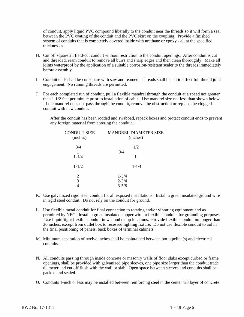
BW2 No. 17-1811 T - 19 Page 6
of conduit, apply liquid PVC compound liberally to the conduit near the threads so it will form a seal between the PVC coating of the conduit and the PVC skirt on the coupling. Provide a finished system of conduits that is completely covered inside with urethane or epoxy - all at the specified thicknesses.
H. Cut off square all field-cut conduit without restriction to the conduit openings. After conduit is cut
and threaded, ream conduit to remove all burrs and sharp edges and then clean thoroughly. Make all joints waterproof by the application of a suitable corrosion-resistant sealer to the threads immediately before assembly.
I. Conduit ends shall be cut square with saw and reamed. Threads shall be cut to effect full thread joint
engagement. No running threads are permitted.
J. For each completed run of conduit, pull a flexible mandrel through the conduit at a speed not greater than 1-1/2 feet per minute prior to installation of cable. Use mandrel size not less than shown below. If the mandrel does not pass through the conduit, remove the obstruction or replace the clogged conduit with new conduit.
After the conduit has been rodded and swabbed, repack boxes and protect conduit ends to prevent any foreign material from entering the conduit.
CONDUIT SIZE MANDREL DIAMETER SIZE (inches) (inches)
3/4 1/2 1 3/4 1-1/4 1
1-1/2 1-1/4
2 1-3/4 3 2-3/4 4 3-5/8
K. Use galvanized rigid steel conduit for all exposed installations. Install a green insulated ground wire
in rigid steel conduit. Do not rely on the conduit for ground.
L. Use flexible metal conduit for final connection to rotating and/or vibrating equipment and as permitted by NEC. Install a green insulated copper wire in flexible conduits for grounding purposes. Use liquid-tight flexible conduit in wet and damp locations. Provide flexible conduit no longer than 36 inches, except from outlet box to recessed lighting fixture. Do not use flexible conduit to aid in the final positioning of panels, back boxes of terminal cabinets.
M. Minimum separation of twelve inches shall be maintained between hot pipeline(s) and electrical
conduits.
N. All conduits passing through inside concrete or masonry walls of floor slabs except curbed or frame openings, shall be provided with galvanized pipe sleeves, one pipe size larger than the conduit trade diameter and cut off flush with the wall or slab. Open space between sleeves and conduits shall be packed and sealed.
O. Conduits 1-inch or less may be installed between reinforcing steel in the center 1/3 layer of concrete

BW2 No. 17-1811 T - 19 Page 7
walls and slabs; and if there is only one layer of reinforcing steel in slabs, the conduits shall be placed under the reinforcement, unless otherwise directed by Owner.
P. Structural members and reinforcing steel shall not be cut, burned or damaged in any way. Holes cut
through existing floors and walls shall be neatly repaired with zinc-coated pipe rings placed on conduits at entry points.
Q. Trapped runs and vertical loops in conduits shall be avoided, if possible, but where necessary, shall
be drained with proper fittings.
R. Conduit shall not be mounted on ductwork or other mechanical equipment except where necessary to make connections to electrical devices which are part of or mounted on such equipment. Where conduit must be installed on equipment, do not cover access doors, controls, removable panels, etc. or otherwise hinder normal maintenance and repair of the equipment. Where it is necessary to make conduit connections to equipment mounted on vibration mounts, liquid-tight flexible conduit shall be used. All conduits shall be clear of structural openings.
S. Conduits crossing structural expansion joints shall have type OZ or DX bounded watertight
expansion and deflection fittings.
T. All conduits shall be clear of structural openings. 3.04 CONDUIT LOCATIONS
A. Heavy Wall Rigid Steel Conduit (RSGC)
1. RGSC may used in all locations inside the pump vault and building except where liquid-tight flexible metal conduit, PVC, PCRGSC, or non-metallic flexible conduit, is required, underground or in runs in concrete slabs.
2. RGSC shall be used for conduits installed below 10-foot height from the finished floor, all
conduits containing wiring rated above 600 volts, conduits subject to mechanical damage, conduits exposed to moisture, all exterior locations subject to weather and all above grade or slab locations unless noted otherwise.
B. Plastic-Coated Rigid Galvanized Steel Conduit (PCRGSC)
1. PCRGSC shall be used in all locations outside the pump vault and the building, unless otherwise noted.
C. Liquid-Tight Flexible Metal Conduit:
1. All motor connections, where conduit is required.
2. All equipment connections subject to vibration or movement, where conduit is required.
D. Polyvinyl-Chloride (PVC) Conduit
1. Schedule 40 PVC conduit shall be installed in concrete slabs (size not to exceed 1" trade size
unless noted otherwise) and all underground locations including ductbanks.
2. PVC conduit shall not be installed in locations requiring conduits listed in A, B, and C above.
BW2 No. 17-1811 T - 19 Page 8
3.05 SUPPORTS AND HANGERS
A. Support and align all raceways, cabinets, boxes, fixtures, etc., in an accepted manner and as specified. Secure all supporting methods by means of toggle bolts in hollow masonry, Hilti expansion bolts in solid masonry, Hilti concrete pre-set inserts or expansion pre-set inserts or expansion bolts in concrete, machine screws, bolts or welding on metal surfaces and wood screws on wood construction.
B. Where conduits are hung from horizontal surfaces, structures, etc., or where conduits are mounted to
vertical surfaces, the conduits shall be supported by 316 stainless steel unistrut hangers at intervals not exceeding 6'-0" and within 3'-0" of any bend, outlet, or junction box; and at, or within one foot of each end.
C. All support hardware, bolts, and nuts shall be stainless steel.
3.06 CUTTING AND PATCHING
Carefully lay out all work in advance, and where cutting, channeling, chasing, or drilling of the concrete structural building surfaces is necessary for the proper installation of electrical equipment, carefully perform this work in a manner approved by the Owner. Damaged surfaces shall be repaired at no cost to the Owner. Concrete shall be cut only with rotary type drilling tools.
3.07 CONDUIT SEALS
Install conduit seals in all location shown on the Drawings and where required by the NEC. 3.08 CONDUIT SLEEVES
The conduit sleeve shall be one trade size larger than the conduit. 3.09 CONDUIT TRENCHING AND BACKFILL
All 480 volt power conduits shall be buried a minimum 36" deep. All 208/120 volt and lower volt conduits shall be a minimum of 24" deep. Trenches shall be a minimum of 6" wide; 8" is preferred for 3" and larger conduits. Trenches shall be free of all rocks and debris larger than 1".
Layer bottom of trench with a minimum 4" of cushion sand, and cover conduit with another 4" of cushion sand. Backfill trench with dirt, with no rocks larger than 1". Pack with a tamper to 95% of density or better of existing surrounding soils.
Concrete encasement (3000 PSI) may be used in lieu of sand backfill and cushion. First position conduit in trench with plastic standoff spacers, 3" above trench floor.
END OF SECTION

BW2 No. 17-1811 T - 20 Page 1
SECTION T- 20 WIRE AND CABLE PART 1 GENERAL 1.01 SCOPE OF WORK
The work performed under this section consists of providing labor, material, tools, equipment and related items required to furnish, install and place into operation all wire and cable systems.
1.02 REFERENCE STANDARDS
A. UL
B. IPCA
C. NEC 1.03 ACCEPTABLE MANUFACTURERS
A. The Okenite Company
B. Capital Wire and Cable
C. Rome Cable
D. Approved equal 1.04 SUBMITTALS If requested, submittals shall include the following:
A. Furnish technical specifications and factory test reports.
B. Insulation type.
C. Temperature rating.
D. Indicate stranded copper conductors. PART 2 PRODUCTS 2.01 600-VOLT INSULATION
Unless otherwise noted, power and control cable shall be single conductor, soft drawn, annealed stranded copper conductors, type THHN or THWN insulation, with 75°C minimum rating and 600 volt insulation rating.

BW2 No. 17-1811 T - 20 Page 2
PART 3 EXECUTION 3.01 WIRE AND CABLE RATED 600 VOLTS FOR CIRCUITS 600 VOLTS AND BELOW
A. Color coded wire shall be used for 600 volts and below. On wire size 6 and larger, colored 3M electrical tape may be used for color coding, over black insulation at wire ends. The following code shall be used, with exceptions noted below:
277/480 Volt, 3-Phase, 4-Wire, or 3 wire delta Phase A - Brown Phase B - Yellow Phase C - Orange Neutral - Gray Ground - Green
120/208-Volt, 3-Phase, 4-Wire, or 3 wire delta Phase A - Black Phase B - Red Phase C - Blue Neutral - White Ground – Green
B. Color coding as required by NEC and used by local authority having jurisdiction shall prevail.
C. If required as part of the project, any #14 wire going to control and monitor panels shall be red or
color coded insulated THHN/THWN.
D. Aluminum wire shall not be used.
E. A wire installed in conduit solely for grounding shall have an identifying green covering.
F. Unless shown or noted otherwise on the Drawings, minimum wire size shall be 12 AWG for power and 14 AWG for controls.
G. A green 600 volt conductor used for grounding purposes with single conductor cables of higher
voltage requirements will be permitted.
H. Conductor terminations, No. 8 AWG and smaller, shall be made with pressure connected lugs, Buchanan Termend or equal. Conductor terminations, larger than No. 8 AWG, shall be made with solderless, compression type copper terminals equivalent to Burndy type YA-L. Compression shall be made with a die set that will make a circumferential crimp. Wire strands shall be thoroughly cleaned and tinned before lug is applied.
I. Bolted connections for electrical conductors, without noncorrosive surfaces, shall be thoroughly
cleaned and tinned or covered with a light film of commercial paste to prevent oxidation.
J. Where mechanical assistance is used for pulling conductors, a wire pulling compound having inert qualities that do not harm the wire insulation or covering shall be applied to the conductors before they are pulled into raceways. Interior of all raceways shall be free from grease, filings or foreign

BW2 No. 17-1811 T - 20 Page 3
matter before conductors are pulled. Wire manufacturer’s recommended pulling tension must not be exceeded.
K. No wire smaller than No. 12 shall be installed, except as furnished with standard packaged
equipment, or specified herein, for low voltage control systems, or fixture wiring.
L. All wiring, except in special cases, shall be run in conduits or raceways. No wire shall be installed until the conduit system is completed and the construction work has progressed beyond the stage where the wire may be damaged.
M. Where the capacity of a single feeder is so great as to require parallel conductors in more than one
conduit, each conduit must contain the same number and length of conductors in all phases (legs) of the feeder, including any neutral conductors.
N. Unless otherwise noted, in circuits of 600 volts and below, control wiring may be pulled in the same
conduit with the power wiring if the control wiring is rated for the same voltage as the power wiring and if the conduit size is adequate. Motors 30 HP and larger shall have separate conduit systems for the motor leads and control wiring.
END OF SECTION

BW2 No. 17-1811 T - 21 Page 1
SECTION T - 21
BOXES AND FITTINGS PART 1 GENERAL 1.01 SCOPE OF WORK
The work performed under this section consists of providing all labor, material, tools, equipment and related items required to furnish and install all junction boxes, pull boxes, ceiling boxes and outlet boxes installed outdoor or indoors.
1.02 REFERENCE STANDARDS
A. UL
B. NEC 1.03 ACCEPTABLE MANUFACTURERS
A. Galvanized Boxes, Gutters, and Enclosures
1. Circle AW
2. Steel-City
3. Universal
4. AMF
5. Approved equal
B. Cast Boxes and Fittings and Outlet Boxes
1. O-Z/Gedney Company
2. Appleton Electric
3. Crouse-Hinds
4. Approved equal
C. Ceiling Boxes and Outlet Boxes
1. Appleton Electric
2. Steel-City
3. Bowers
4. Approved equal
BW2 No. 17-1811 T - 21 Page 2
D. Plastic-Coated and Non-Metallic Boxes and Fittings
1. Robroy Industries
2. Carlon
3. OCAL-BLUE
4. Approved equal 1.04 SUBMITTALS
A. If requested, submittals shall include the following:
1. Manufacturer’s name and current model number
2. Manufacturer’s standard cut-sheet PART 2 PRODUCT 2.01 MATERIALS
A. Pull and junction boxes for non-shielded conductors shall be galvanized after fabrication, furnished with a cellular neoprene gasket and sized according to the requirements of the National Electrical Code.
B. The Contractor shall size all pull and junction boxes in accordance with the requirements of the
National Electrical Code.
C. Bolt-on junction box covers, 30 inches square or larger, shall have a rigid handle. Covers larger than 3'-0" by 4'-0" shall be split.
D. Convenience outlet boxes shall be galvanized formed sheet metal, 4-inch square by 1-1/2 inches deep
or larger for flush mounted outlets with extension rings provided. Outlet boxes for surface mounting shall be zinc-coated cast metal, type FD or FS.
E. Device or utility boxes shall be of unit construction of a size required for the number of switches or
outlets required. No sectional device boxes will be permitted.
F. Boxes installed in corrosive atmospheres where PSRGS or PVC conduit is used shall be weatherproof, non-corroding, type FS, FD, FSE, FSD, FSC, FDG, FSS, 2FSE, FSCC or 2FSC as manufactured by Crouse Hinds, Carlon, Robroy, or equal.
G. Ceiling outlets shall be galvanized and shall be 4-inch octagonal by 2-1/8 inches deep for exposed
ceiling use, and 4-inch octagonal by 3-inches deep for paved concrete work unless otherwise specified. Boxes shall have plaster rings and fixture studs where required.

BW2 No. 17-1811 T - 21 Page 3
PART 3 EXECUTION 3.01 DELIVERY AND STORAGE
A. Delivery
Prepare boxes, fittings, and accessories for shipment.
B. Storage and Handling at Job Site
The Contractor shall store and handle all boxes and fittings at the job site, while such materials are awaiting installation, in conformance with the following:
1. Store boxes, fittings, and accessories in an area protected from weather, moisture or possible
damage.
2. Do not store material directly on the ground. 3.02 INSTALLATION
A. All outlet boxes will be mounted with suitable fasteners, and they shall contain the proper hubs. All unused hubs will be closed off. Outlet or utility boxes concealed in construction shall be firmly secured in place, set true, square and flush with the finished surface for the correct application of cover plates or other devices.
B. Outlet boxes for receptacles and switches shall be deep boxes; shallow boxes are permitted only when
space for a deep box is inadequate.
END OF SECTION
BW2 No. 17-1811 T - 22 Page 1
SECTION T - 22
WIRING DEVICES AND PLATES PART 1 GENERAL 1.01 SCOPE OF WORK
The work prepared under this section of the Specifications consists of providing labor, materials, tools, equipment and rotated items required to furnish, install and place into operations all wiring devices, such as switches, convenience outlets, and special outlets, and all device plates and special outlet boxes.
1.02 REFERENCE STANDARDS
A. NEMA
B. UL
C. NEC
1.03 ACCEPTABLE MANUFACTURERS
A. Switches:
1. Bryant
2. Hubbell
3. Leviton
4. P&S
5. Approved Equal
B. Receptacles:
1. Bryant
2. Hubbell
3. Leviton
4. P&S
5. Approved Equal
1.04 SUBMITTALS
BW2 No. 17-1811 T - 22 Page 2
If requested, submittals shall include the following:
A. Manufacturer and current model number.
B. Switch and receptacle ratings.
C. Device material and color.
D. Manufacturer’s standard cut-sheet including technical specifications for devices. PART 2 PRODUCTS 2.01 DEVICES
A. Switches shall be specification grade rated 20 amperes, 125 volts with ivory color.
B. Duplex convenience outlets shall be 3 wire, grounding, 20 amp, 125 volts, NEMA 5-20R, with ivory color.
C. All receptacles shall be grounding type with provisions for back and side wiring.
D. Each branch circuit shall have a GFI-type receptacle protecting the circuit, with test and reset pushbutton.
2.02 DEVICE PLATE AND COVERS
A. Stainless steel plates shall be 302 grade used on surface and flush-mounted outlet boxes.
B. Plate mounting screws shall be stainless steel or brass and painted to match plate color.
C. Weatherproof outlet covers shall be used outdoors with spring door with hasp suitable for pad locking in the closed door position, and shall be of the cast alloy or Feraloy type.
D. Covers shall be as noted on drawings. PART 3 EXECUTION 3.01 DELIVERY AND STORAGE
A. Delivery
Prepare wiring devices and accessories for shipment in weatherproof and crush-resistant packaging.
B. Storage and Handling at Job Site
The Contractor shall store and handle all wiring devices at the job site, in accordance with the following:

BW2 No. 17-1811 T - 22 Page 3
a. Store wiring devices and accessories in an area protected from weather, moisture or possible damage.
b. Do not store materials directly on the ground.
c. Handle items to prevent damage to interior or exterior surfaces. 3.02 INSTALLATION
A. Wall or lighting switches shall be mounted 4'-6" above floor or grade unless noted otherwise.
B. Install convenience outlets and wall or lighting switches in an accessible location with 2 foot minimum from obstructions.
C. Convenience outlets outdoors and in locations or rooms where equipment can be hosed down shall be weatherproof, and watertight.
END OF SECTION
BW2 No. 17-1811 T – 23 Page 1
SECTION T- 23
DISCONNECT SWITCHES FOR CIRCUITS PART 1 GENERAL 1.01 SCOPE OF WORK
The work performed under this section consists of providing all labor, materials, tools, equipment and related items required to furnish, install and place into operation all fusible or non-fusible motor and circuit disconnect switches and all manual motor switches.
1.02 REFERENCE STANDARDS
A. NEC
B. OSHA
C. ANSI
D. IEEE
E. NEMA
F. UL 98 1.03 ACCEPTABLE MANUFACTURERS
A. Square D Company
B. General Electric
C. Siemens
D. Approved equal 1.04 SUBMITTALS
A. If requested, submittals shall include the following: a. Manufacturer’s name and model number
b. Voltage, current, and horsepower rating
c. NEMA type enclosure
d. Enclosure dimensions
e. Fuse or circuit breaker rating and type f. Name plate information
BW2 No. 17-1811 T – 23 Page 2
PART 2 PRODUCTS 2.01 GENERAL
A. All switches shall be heavy duty, NEMA horsepower rated and UL listed.
B. All switches shall carry UL label for service entrance duty where required. 2.02 ENCLOSURE
A. NEMA Type 12 for interior applications.
B. NEMA Type 3R for all exterior applications or where subject to rain or splashing water.
C. All switches shall have an exterior handle lockable in either the ON or OFF positions. Handle shall be an integral part of the box.
D. Covers where part of the enclosure shall have capability of being locked to enclosure box.
E. Interlock mechanism shall prevent opening of disconnect switch door while in the ON position. 2.03 DISCONNECT SWITCHES
A. Switch blades shall be fully visible in the OFF position when the switch door is open.
B. Switches shall have removable arc suppressors to allow access to switch interior.
C. Current carrying parts shall be plated to provide maximum life.
D. Switches shall be quick-make, quick-break type.
E. All switches shall have 600 Volt rating with ampacity or horsepower rating as indicated on the Drawings.
2.04 FUSES
Fuses shall be provided when and as specified on the Drawings. 2.05 CIRCUIT BREAKERS
Circuit breakers shall be provided when and as specified on the Drawings. 2.06 TERMINALS
A. UL listed for Copper, 60°C or 75°C wire.
B. Lugs shall be copper and screw or compression type.

BW2 No. 17-1811 T – 23 Page 3
C. Furnish grounding lug for all switches. 2.07 NAMEPLATES
A. Furnish nameplate for all switches in accordance with specifications.
B. Nameplate shall indicate equipment served, voltage, and amperage. PART 3 EXECUTION 3.01 DELIVERY AND STORAGE
A. Delivery. Prepare motor and circuit disconnect switches and accessories for shipment to the job site.
B. Storage and Handling at Job Site. The Contractor shall store and handle all disconnect switches at the job site in accordance with the following:
1. Store disconnect switches and accessories in an area protected from weather, moisture or possible
damage. 2. Do not store materials directly on the ground.
3. Handle items to prevent damage to interior or exterior surfaces.
3.02 INSTALLATION
A. Secure switch cabinet to surface using screws, bolts, or mounting devices specifically made for the application.
B. Where more than one wire is used per phase, a lug shall be furnished for each wire installed.
END OF SECTION
BW2 No. 17-1811 T - 24 Page 1
SECTION T -24
CIRCUIT BREAKERS PART 1 GENERAL 1.01 SCOPE OF WORK
The work performed under this section consists of providing all labor, materials, tools, equipment and related items required to furnish, install and place into operation all molded case circuit breakers whether installed in a panelboard, control center, disconnect switch, starter, or any other equipment circuit breakers.
1.02 REFERENCE STANDARDS
A. NEC
B. ANSI
C. IEEE
D. NEMA 1.03 ACCEPTABLE MANUFACTURERS
A. Square D Company
B. General Electric Company
C. Siemens
D. Approved equal 1.04 SUBMITTALS
A. If requested, submittals shall include the following:
1. Manufacturer’s name and current model number.
2. Manufacturer’s data sheet describing the type of circuit breaker.
3. Amperage rating.
4. Magnetic trip rating on thermal magnetic circuit breakers and magnetic trip range in amperes on motor circuit protectors (magnetic only circuit breakers).
BW2 No. 17-1811 T - 24 Page 2
PART 2 PRODUCTS 2.01 GENERAL
A. Molded case circuit breakers shall be used for the protection of all branch circuits unless noted otherwise on the Drawings. Circuit breakers shall be UL-listed; have a quick-break, over-center toggle type mechanism; and be trip-free type with trip indication by handle position. Two- and three-pole circuit breakers shall have common trip. Contact shall be of a silver-alloy material.
B. Where circuit breakers are used to switch lighting fixtures, heaters, etc., that circuit breaker shall be UL-listed for switching duty.
2.02 MOLDED CASE CIRCUIT BREAKERS
A. Circuit breakers shall be 1-inch wide for one pole, 2-inches wide for two pole, and 3-inches wide for three pole minimum width. No 2-inch wide or tandem circuit breakers will be used.
B. Branch thermal-magnetic circuit breakers mounted in panelboards shall have fixed magnetic trip, normal duty rating for 20,000 amperes interrupting current. Provide bolt-on type circuit breakers with trip ratings as scheduled on the Drawings equal to Square D Company NQOB. Main circuit breakers shall have an interrupting rating not less than that of the panelboard.
C. All Main Service circuit breakers for 480 volt service shall be Square D I-Limiter type breakers. The main breaker shall limit fault current, to less than 1/4 cycle, and be able to withstand (rating may be higher, but not lower) a maximum A.I.C. rating as shown on the Drawings, or 30,000 amps. Instantaneous trip, magnetic only circuit breakers shall be used only in conjunction with, and immediately ahead of motor-running, over-current, protective devices as herein specified or as noted on the Drawings as motor circuit protector (MCP) or in a Motor Control Center. They shall have a single front accessible and adjustable magnetic trip setting which simultaneously sets the magnetic trip level of each individual pole. The interrupting rating shall not be less than that of the motor control center or started where the breaker is installed.
PART 3 EXECUTION 3.01 DELIVERY AND STORAGE
A. Delivery. Prepare circuit breakers and accessories for shipment to the job site.
B. Storage and Handling at Job Site. The Contractor shall store and handle all circuit breakers at the job site, in accordance with the following:
1. Store circuit breakers and accessories in an area protected from weather, moisture or possible
damage.
2. Do not store materials directly on the ground.
3. Handle items to prevent damage to interior or exterior surfaces.

BW2 No. 17-1811 T - 24 Page 3
3.02 LUGS
All circuit breakers shall be capable of accepting copper, aluminum, or copper-clad aluminum wiring. Furnish lugs which are constructed for the number and size of conductors which will be installed. All wiring is to be copper.
3.03 INSTALLATION
Mount circuit breakers in panelboards or control centers or motor control centers in accordance with the manufacturer’s recommendations. Securely fasten bolt-on circuit breakers to assure positive connection to the panelboard bussing. Where main circuit breakers are installed, mount the circuit breaker upright in the center top-center.
END OF SECTION

BW2 No. 17-1811 T – 25 Page 1
SECTION T - 25
GROUNDING PART 1 GENERAL 1.01 SCOPE OF WORK
The work performed under this Section consists of providing all labor, materials, tools, equipment and related items required to furnish and install a radial electrical grounding system in conduits and equipment safety grounding.
1.02 REFERENCE STANDARDS
A. NEC
B. NESC
C. IEEE Standard 142-1972 (Recommended Grounding)
D. UL PART 2 PRODUCTS 2.01 MATERIAL
All wire and fittings shall be 98 percent conductivity copper. PART 3 EXECUTION 3.01 SYSTEM GROUNDING
A. The secondary of all alternating current distribution systems which are to be grounded shall have the common or grounding conductor connected directly to the grounding rod.
B. All ground rods shall be located at least two foot away from foundations and concrete structures.
C. The grounding wires shall be sized per NEC Article 250 or as shown on Drawings, if larger, and connected to a separate ground lug or bus in the equipment.
D. All equipment shall be grounded and solidly bonded together.
3.02 SAFETY GROUNDING OF EQUIPMENT
Safety grounding of equipment will be accomplished by providing an equipment wire, as shown on the Drawings which will be no less than the size recommended in Article 250 of the National Electrical Code. This ground shall be routed in conduit to a ground rod to assure that all equipment enclosures are grounded. All fencing shall also be grounded. All metal buildings shall be grounded.

BW2 No. 17-1811 T – 25 Page 2
3.03 GROUND RODS
A. Ground rods shall be copper clad steel, 3/4" diameter by 10' long.
B. All connections shall use thermo welding process equal to CADWELD. Use the correct mold and configuration for the application.
3.04 GROUNDING TESTS
A. Ground rods and main ground connection on main service entrance and motor control center shall be tested using Fall of Potential method under reasonably dry conditions and demonstrating resistance of test item to ground of 3 ohms or less.
B. Contractor shall add additional ground rods and ground wells as required to achieve this low resistance ground of 3 ohms or less.
C. Contractor shall conduct ground resistance measurement tests witnessed by Owner’s Representative and submit a copy of test data to the Owner’s Representative and to the Engineer.
END OF SECTION

BW2 No. 17-1811 T - 26 Page 1
SECTION T - 26
LIGHTING PART 1 GENERAL 1.01 SCOPE OF WORK
The work performed under this Section consists of providing all labor, material, tools, equipment and related items required to furnish, install and place into operation lighting fixtures, supports, and accessories.
1.02 REFERENCE STANDARDS
A. NEC
B. OSHA
C. ANSI
D. IES
E. IEEE
F. NEMA
G. UL
H. NESC 1.03 COORDINATION
Locations of lighting fixtures shown on the Drawings are approximate only. The final location shall be dependent on physical conditions encountered during construction. Where lighting fixtures conflict with work by other trades, and must be relocated, the Contractor shall have written approval from the Owner prior to relocating the fixture(s).
PART 2 PRODUCTS 2.01 LIGHTING FIXTURE TYPE
A. All lamps shall be LED type.
B. The lighting fixture type and manufacturer shall be as specified or shown on the Drawings.
C. Lighting fixtures with the same function and performance shall be acceptable as substitutions upon approval by the Owner.
D. Furnish all fixtures with high temperature drivers. 2.02 FINISH

BW2 No. 17-1811 T - 26 Page 2
Prime coat all metal surfaces prior to application of two coats of finish paint.
PART 3 EXECUTION 3.01 DELIVERY AND STORAGE
A. Delivery. Prepare lighting fixtures and accessories for shipment to the job site.
B. Storage and Handling at Job Site. The Contractor shall store and handle all lighting fixtures at the job site, while such materials are awaiting installation, in accordance with the following:
1. Store lighting fixtures and accessories in an area protected from weather, moisture or possible
damage.
2. Do not store materials directly on the ground.
3. Handle items to prevent damage to interior or exterior surfaces. 3.02 INSTALLATION
A. Provide luminaries complete with gaskets forming weather-proof assembly, where required.
B. Install wiring in conduit with watertight connections.
END OF SECTION
BW2 No. 17-1811 T - 27 Page 1
SECTION T - 27
ELECTRICAL HEATERS PART 1 GENERAL 1.01 WORK INCLUDED
Furnish labor, materials, equipment and incidentals necessary to install electric unit heaters, wall heaters, or other electrical heating devices, along with related accessories and components.
1.02 QUALITY ASSURANCE
A. ACCEPTABLE MANUFACTURER
Products which meet the specification as manufactured by the following companies will be acceptable: 1. ELECTRICAL WALL HEATERS
Qmark Emerson Markel Approved equal
B. CERTIFICATION
Unit heaters shall be certifies by the AMCA “Air Movements and Control Association” and the Underwriter’s Laboratory. Electrical components shall be listed by the Underwriter’s Laboratory.
C. FACTORY TESTING
Packaged equipment shall be assembled and tested at the factory before shipment to the project. 1.03 SUBMITTALS
Submittals shall include factory product data sheets showing engineering data and performance criteria for each heater. Information shall include fan performance rating, horsepower and electrical characteristics, CFM, output ratings and other engineering data necessary for a complete evaluation of the product.
1.04 DELIVERY AND STORAGE
Ship equipment inside protective crates and store inside containers until erected in the structure. Arrange to have the proper equipment for unloading and handling of equipment at the site to prevent damage.

BW2 No. 17-1811 T - 27 Page 2
1.05 JOB CONDITIONS
Heaters shall be installed and completed, then run for a period of not less than two (2) weeks to determine that the units are performing as specified and to allow testing of controls and other related components. The operation of these units will not in any manner affect the starting date of the warranty periods.
1.06 GUARANTEES
Furnish the Manufacturer’s printed warranty for each separate item, along with Contractor’s written one (1) year guarantee. Warranty shall include the labor necessary to replace defective parts during the warranty period.
PART 2 PRODUCTS 2.01 MATERIALS
A. STEEL SUPPORTS AND FRAMES: A-36 grade not rolled steel shaped. Unless otherwise noted on the drawings or details, minimum sizes of supports shall be 3” x 4” x 3/8” angles up to a span of 5’-0” and 4” x 5” x 3/8” for other spans.
B. ELECTRICAL HEATERS:
1. Heating elements shall be a totally enclosed corrosion resistant finned element. Motors shall be heavy duty, permanently lubricated, and totally enclosed type, impedance protected. Propeller shall be directly connected to motor.
2. Furnish a unit with thermal cutout, circuit breaker, and contactor, completely factory-wired, and
ready for a single point electrical connection. The Manufacturer shall furnish an appropriate thermostat built in to the unit.
PART 3 EXECUTION 3.01 INSTALLATION
Wall heaters shall be as specified and installed in accordance with the Manufacturer’s written instructions. Install recessed unit inside a sleeve installed into a recessed formed in the wall. Units shall have internal thermostats furnished by the Manufacturer that are factory-wired. Make electrical connections.
END OF SECTION
BW2 No. 17-1811 T-28 Page 1
SECTION T - 28
TRANSFORMERS PART 1 GENERAL
A. Supply and install transformers of capacity indicated on Drawings and where indicated on the drawings.
B. Transformers shall be as manufactured by G.E., Square "D", Eaton (Cutler Hammer) or Siemens
(ITE).
C. Transformers shall have (2)- 2-1/2% taps FCBN and (4)- 2-1/2% taps FCAN and with neutral brought out for grounding.
PART 2 PRODUCTS
A. Transformers shall be indoor dry type and shall be self-cooled by natural draft, Class H insulation, 40o C ambient temperature and shall be manufactured in accordance with NEMA and ASA standards for transformers.
B. Except as otherwise specified, noise level of each transformer shall not exceed the following
when measured in accordance with ASA C 89.1, 1961 standards:
1. 15 KVA and below - 40 db
2. 30-150 KVA - 50 db
3. 167-300 KVA - 55 db
C. Equipment furnished under this section shall be by switchgear manufacturer. PART 3 EXECUTION
A. Mount transformer on housekeeping pads as shown, or on vibration isolators of type recommended by manufacturer.
B. Install as recommended by Manufacturer.
END OF SECTION
BW2 No. 17-1811 T - 29 Page 1
SECTION T - 29
DISTRIBUTION AND LIGHTING PANELBOARDS PART 1 GENERAL
A. Panelboards shall consist of a box, dead front, interior and circuit protective devices and shall be manufactured in accordance with NEMA standards and bear applicable Underwriters' Laboratories labels.
B. The box shall be fabricated from code gauge galvanized sheet steel in accordance with the latest UL
standards and shall have a turned edge around the front for rigidity and for clamping on front. Standard knockouts shall be provided. The front shall be fabricated from sheet steel and finished with baked on gray enamel over a rust inhibitor. Each front shall have a door mounted on semi-concealed hinges with a cylinder lock, index card and cardholder. All panelboard locks shall be master keyed and all index cards shall be properly completed on a typewriter. Boxes shall be nominally 22" wide and 5-3/4" deep.
C. The interiors shall consist of a factory assembled rigid frame, supporting the rectangular bus, the
mains and the neutral bar. The bussing shall be copper or aluminum arranged for sequence phasing throughout and have a current density to maintain a maximum 65 degree C. temperature rise over a 40 degree C. ambient temperature. The neutral bar shall be located at the opposite end of the structure from the mains and shall have numbered terminals. The mains shall have either solderless lugs or a main circuit protective device as scheduled.
D. The circuit protective devices shall be molded case circuit breakers of the quick-make, quick-break
thermal magnetic type and shall be operated by means of toggle type mechanism with trip indication. The number of poles, ampere rating and trip rating of the breakers shall be as scheduled. The short circuit rating shall be in accordance with NEMA standards for sizes required. All circuit breakers shall be of the bolt-in-type. Breakers shall be rated for not less than 22,000 A.I.C. RMS symmetrical.
E. Approved Manufacturers:
General Electric Siemens (ITE) Square "D" Eaton (Cutler Hammer)
PART 2 PRODUCTS
A. Refer to other sections PART 3 EXECUTION
BW2 No. 17-1811 T - 29 Page 2
A. All panelboards shall be of a single manufacturer unless noted otherwise.
B. There shall be no splices, tap, or joints within a panelboard enclosure.
C. There shall be one (1) conductor terminated on each Branch Circuit Breaker.
D. The electrical contractor shall notify the Engineer when feeders are to be torqued so that a
representative of the Engineer or Owner may witness the torqueing process.
E. All panelboards shall be provided with a typed panelboard schedules in a clear plastic holder attached to the inside of the panel door.
F. Panelboard schedules shall be typewritten and shall indicated panel name, volts, phase, Hertz, amp
rating and shall note each circuit by number and the specific area/load served.
END OF SECTION

BW2 No. 17-1811 T - 30 Page
1
SECTION T-30
MOTOR CONTROL CENTERS
PART 1 GENERAL
1.01 DESCRIPTION
A. This section includes requirements for motor control centers (MCC) and all required control devices as shown on the drawings and specified to be part of the MCC equipment. The MCC shall be 480 V, 3-Phase, 4-Wire, 60 Hz unless otherwise indicated.
1.02 REGULATORY REQUIREMENTS
A. The MCC shall conform to Underwriters Laboratory (UL) 845, current revision, NEMA ICS-2, the latest version of the National Electrical Code.
1.03 SUBMITTALS
A. Submit shop drawings indicating the following:
1. Front view of enclosure with overall dimensions
2. Single line diagram
3. Top and bottom conduit entrance / exit locations with dimensions
4. Electrical characteristics of the MCC
5. Specified ratings
6. Bill-of-material
7. Shipping splits and weights
8. Wiring diagrams with control scheme.
9. Operational instructions for key lock schemes, throw-over schemes, and other special instructions
1.04 INSTALLATION AND MAINTENANCE DATA
A. Provide with the delivery of the MCC one (1) Installation and Maintenance Manual and one (1) copy of the manufacturer's drawings per shipping block.
B. Provide one (1) copy of complete Operations and Maintenance Manual on CD ROM
1.05 PACKING/SHIPPING
A. The MCC shall be separated into shipping blocks no more than three vertical sections each. Shipping blocks shall be shipped on their sides to permit easier handling at the jobsite. Each shipping block shall include a removable lifting angle, which will allow an easy means of attaching an overhead crane or other suitable lifting equipment.
1.06 STORAGE
A. If the MCC cannot be placed into service in a reasonable time period after its receipt, it shall be stored in a clean, dry, and ventilated building free from temperature extremes. Acceptable storage temperatures shall be from 0° C (32° F) to 40° C (104° F).

BW2 No. 17-1811 T - 30 Page
2
1.07 WARRANTY
A. Manufacturer shall warrant equipment to be free from defects in materials and workmanship for eighteen (18) months from date of shipment by the manufacturer.
PART 2 PRODUCT
2.01 APPROVED MANUFACTURERS
A. Square D by Schneider Electric, Class 8998 Model 6.
2.02 MATERIALS
A. Steel material shall comply with UL 845.
B. Each MCC shall consist of one or more vertical sections of heavy gauge steel bolted together to form a rigid, free-standing assembly. A removable seven (7) gauge structural steel lifting angle shall be mounted the full width of the MCC lineup at the top. Removable seven (7) gauge bottom channel sills shall be mounted underneath front and rear of the vertical sections extending the full width of the lineup. Vertical sections shall be made of a welded side-frame assembly formed from a minimum of twelve (12) gauge steel. Internal reinforcement structural parts shall be constructed of eleven (11) gauge steel to provide a strong, rigid assembly. The entire assembly shall be constructed and packaged to withstand all stresses included in transit and during installation.
2.03 MCC FINISH
A. All steel parts shall be provided with UL listed acrylic/alkyd baked enamel paint finish, except plated parts used for ground connections. All painted parts shall undergo a multi-stage treatment process, followed by the finishing paint coat.
B. Pre-treatment shall include:
1. Hot alkaline cleaner to remove grease and oil.
2. Iron phosphate treatment to improve adhesion and corrosion resistance.
C. The paint shall be applied using an electro-deposition process to ensure a uniform paint coat with high adhesion.
D. The standard paint finish shall be tested to UL 50 per ASTM B117 (5% ASTM Salt Spray) with no greater than 0.125 in (3 mm) loss of paint from a scribed line.
E. Paint color shall be manufacturers standard ANSI 49 medium-light grey. Control station plates and escutcheon plates shall be painted a contrasting grey. All unit interior saddles shall be painted white for better visibility inside the unit.
2.04 STRUCTURES
A. Structures shall be totally enclosed, dead-front, free-standing assemblies. Structures shall be capable of being bolted together to form a single assembly.
BW2 No. 17-1811 T - 30 Page
3
B. The overall height of the MCC shall not exceed 91.5”, including base channel. The total width of a standard section shall be 20”. At the Manufacturer’s option, alternate widths of 25”, 30”, and 35” shall be utilized for larger devices.
C. Structures shall be NEMA 1 General Purpose indoor.
D. Each 20” wide standard section shall have all the necessary hardware and bussing for modular plug-in units to be added and moved around. All unused space shall be covered by hinged blank doors and equipped to accept future units. Vertical bus openings shall be covered by manual bus shutters.
E. Each section shall include a single piece top plate. Top plates shall be removable for ease in cutting conduit entry openings.
2.05 WIREWAYS
A. Structures shall contain a minimum twelve (12) inch high horizontal wireway at the top of each section and a minimum six (6) inch high horizontal wireway at the bottom of each section. These wireways shall run the full length of MCC to allow room for power and control cable to connect between units in different sections.
B. A full-depth vertical wireway shall be provided in each MCC section that accepts modular plug-in units. The vertical wireway shall connect with both the top and bottom horizontal wireway and shall be isolated from unit interiors by a full height barrier. The vertical wireway shall be a minimum of four (4) inches wide minimum with a separate hinged door. Access to the wireways shall not require opening control unit doors. Structures that house a single, full section control unit shall not be required to have vertical wireways. Those control units shall open directly into the MCC horizontal wireways.
2.06 BARRIERS
A. All power bussing and splice connections shall be isolated from the unit compartments and the wireways. The horizontal bus shall be mounted onto a glass filled polyester support assembly that braces the bus against the forces generated during a short circuit. The horizontal bus shall be isolated from the top horizontal wireway by a two-piece grounded steel barrier. This barrier shall be removable to allow access to the bus and connections for maintenance.
B. The vertical bus shall be housed in a molded glass-filled polyester support that provides bus insulation and braces the bus against the forces generated during a short circuit. These supports shall have openings every three (3) inches for unit stab-on connections. Each opening shall be provided with a manual shutter to close off the stab opening. These shutters shall be attached to the structure so that when they are removed to allow a stab connection they are retained in the structure and are readily accessible for use should a plug-in unit be removed from the MCC.
C. Barriers shall be provided in the vertical structure and unit designs to prevent the contact of any energized bus or terminal by a fishtape inserted through the conduit or wireway areas.
2.07 BUSSING
A. All bussing and connectors shall be tin-plated copper.

BW2 No. 17-1811 T - 30 Page
4
B. The main horizontal bus shall have a continuous rating of 800 A and shall extend the full length of the MCC. Bus ratings shall be based on 65° C maximum temperature rise in a 40° C ambient. Provisions shall be provided for splicing additional sections onto either end of the MCC.
C. The horizontal bus splice bars shall be pre-assembled into a captive bus stack. This bus stack shall be installed into the end of the MCC power bus to allow the installation of additional sections.
D. Each section that accepts plug-in units shall be provided with a vertical bus for distributing power from the main bus to the individual plug-in starter units. This bus shall be of the same material and plating as the main bus, and shall be rated at 300 A continuous. The vertical bus shall be connected directly to the horizontal bus stack without the use of risers or other intervening connectors.
E. A tin-plated copper ground bus shall be provided that runs the entire length of the MCC. The ground bus shall be 0.25” x 1.0” and be rated for 300 amps. A compression lug shall be provided in the MCC for a 4/0-250 kcmil ground cable. The ground bus shall be provided with a minimum of six (6) 0.38” holes for each vertical section to accept customer-supplied ground lugs for any loads requiring a ground conductor.
F. Each vertical section shall have a copper vertical ground bus that is connected to the horizontal ground bus. This vertical ground bus shall be installed so that the plug-in units engage the ground bus prior to engagement of the power stabs and shall disengage only after the power stabs are disconnected upon removal of the plug-in unit.
G. The power bus system shall be braced for a short circuit capacity of 65,000 rms amperes.
2.08 UNIT CONSTRUCTION
A. Units with circuit breaker disconnects through 400 A frame, and fusible switch disconnects through 400 A, shall connect to the vertical bus through a spring reinforced stab-on connector. Units with larger disconnects shall be connected directly to the main horizontal bus with appropriately sized cable or riser bus. Stabs on all plug-in units shall be solidly bussed to the unit disconnect. Cable connected stab assemblies shall not be permitted.
B. All conducting parts on the line side of the unit disconnect shall be shrouded by a suitable insulating material to prevent accidental contact with live parts.
C. Unit mounting shelves shall include hanger brackets to support the unit weight during installation and removal. All plug-on units shall utilize a twin-handle cam lever located at the top of the bucket to rack in and out the plug-on unit. The cam lever shall work in conjunction with the hanger brackets to ensure positive stab alignment.
D. A cast metal handle operator shall be provided on each disconnect. With the unit stabs engaged into the vertical phase bus and the unit door closed, the handle mechanism shall allow complete ON/OFF control of the unit disconnect with clear indication of the disconnects status. All circuit breaker operators shall include a distinct and separate TRIPPED position to clearly indicate a circuit breaker trip condition. It shall be possible to reset a tripped circuit breaker without opening the control unit door.
E. A mechanical interlock shall prevent the operator from opening the unit door when the disconnect is in the ON position. An additional mechanical interlock shall prevent the operator from placing the
BW2 No. 17-1811 T - 30 Page
5
disconnect in the ON position while the unit door is open. It shall be possible for authorized personnel to defeat these interlocks.
F. A non-defeatable interlock shall be provided between the handle operator and the cam lever to prevent installing or removing a plug-on unit unless the disconnect is in the OFF position.
G. The plug-in unit shall have a grounded stab-on connector which engages the vertical ground bus prior to, and releases after, the power bus stab-on connectors.
H. Provisions shall be provided for locking all disconnects in the OFF position with up to three padlocks.
I. Handle mechanisms shall be located on the left side to encourage operators to stand to the left of the unit being switched.
J. Unit construction shall combine with the vertical wireway isolation barrier to provide a fully compartmentalized design.
2.09 MAIN CIRCUIT BREAKER
A. Electronic trip, standard function 100% rated, molded case circuit breaker.
1. Individually fixed mounted.
a. Circuit breaker shall have power terminals to accommodate either cable or bolted bus connections.
b. Provide the following time/current curve shaping adjustments to maximize system selective coordination. Each adjustment shall have discrete settings and each function is independent from all other adjustments.
LSI:
Adjustable Long Time Ampere Rating and Delay
Adjustable Short Time Pickup and Delay with I²t “IN” ramp.
Adjustable Instantaneous Pickup
High Level Override
Trip indicator for indication of Overload and Short Circuit trip.
c. Terminations
All lugs shall be UL Listed to accept solid and/or stranded copper conductors only. Lugs shall be suitable for 75° C rated wire, or 90° C rated wire sized according to the 75° C temperature rating tables in the NEC.
2.10 BRANCH CIRCUIT BREAKERS
A. Provide Thermal-magnetic type as scheduled.
2.11 SOLID STATE REDUCED VOLTAGE SOFT STARTERS
A. Provide Motor Control Center Soft Start Controllers as scheduled.
2.12 VARIABLE FREQUENCY DRIVES
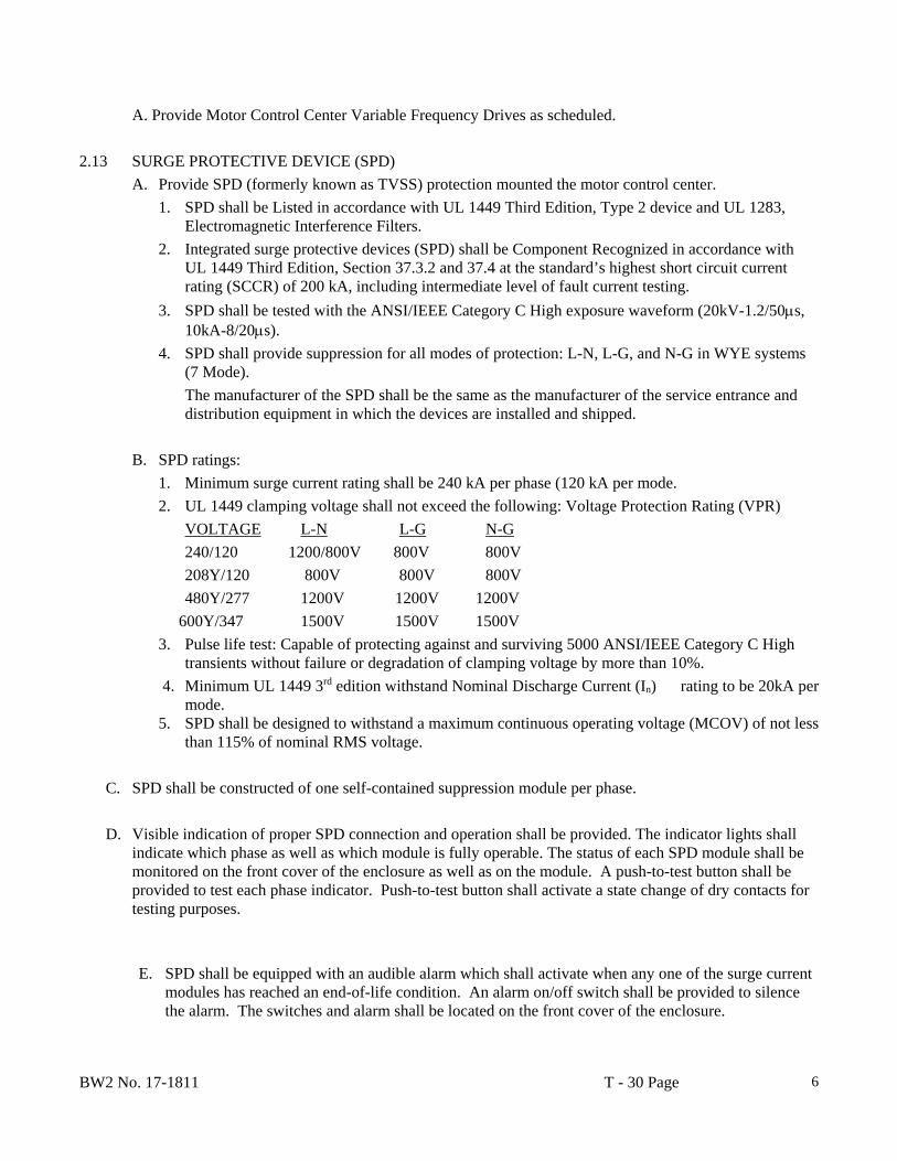
BW2 No. 17-1811 T - 30 Page
6
A. Provide Motor Control Center Variable Frequency Drives as scheduled.
2.13 SURGE PROTECTIVE DEVICE (SPD)
A. Provide SPD (formerly known as TVSS) protection mounted the motor control center.
1. SPD shall be Listed in accordance with UL 1449 Third Edition, Type 2 device and UL 1283, Electromagnetic Interference Filters.
2. Integrated surge protective devices (SPD) shall be Component Recognized in accordance with UL 1449 Third Edition, Section 37.3.2 and 37.4 at the standard’s highest short circuit current rating (SCCR) of 200 kA, including intermediate level of fault current testing.
3. SPD shall be tested with the ANSI/IEEE Category C High exposure waveform (20kV-1.2/50s, 10kA-8/20s).
4. SPD shall provide suppression for all modes of protection: L-N, L-G, and N-G in WYE systems (7 Mode).
The manufacturer of the SPD shall be the same as the manufacturer of the service entrance and distribution equipment in which the devices are installed and shipped.
B. SPD ratings:
1. Minimum surge current rating shall be 240 kA per phase (120 kA per mode.
2. UL 1449 clamping voltage shall not exceed the following: Voltage Protection Rating (VPR)
VOLTAGE L-N L-G N-G
240/120 1200/800V 800V 800V
208Y/120 800V 800V 800V
480Y/277 1200V 1200V 1200V
600Y/347 1500V 1500V 1500V
3. Pulse life test: Capable of protecting against and surviving 5000 ANSI/IEEE Category C High transients without failure or degradation of clamping voltage by more than 10%.
4. Minimum UL 1449 3rd edition withstand Nominal Discharge Current (In) rating to be 20kA per mode.
5. SPD shall be designed to withstand a maximum continuous operating voltage (MCOV) of not less than 115% of nominal RMS voltage.
C. SPD shall be constructed of one self-contained suppression module per phase.
D. Visible indication of proper SPD connection and operation shall be provided. The indicator lights shall indicate which phase as well as which module is fully operable. The status of each SPD module shall be monitored on the front cover of the enclosure as well as on the module. A push-to-test button shall be provided to test each phase indicator. Push-to-test button shall activate a state change of dry contacts for testing purposes.
E. SPD shall be equipped with an audible alarm which shall activate when any one of the surge current modules has reached an end-of-life condition. An alarm on/off switch shall be provided to silence the alarm. The switches and alarm shall be located on the front cover of the enclosure.

BW2 No. 17-1811 T - 30 Page
7
F. A connector shall be provided along with dry contacts (normally open or normally closed) to allow connection to a remote monitor or other system. The output of the dry contacts shall indicate an end-of-life condition for the complete SPD or module.
G. Terminals shall be provided for necessary power and ground connections.
H. The SPD shall be equipped with a transient voltage surge counter located on the diagnostic panel on the front cover of the enclosure. The counter shall be equipped with a manual reset and battery backup to retain memory upon loss of AC power.
I. SPD shall have a warranty for a period of ten (10) years from date of invoice. Warranty shall be the responsibility of the electrical distribution equipment manufacturer and shall be supported by their respective field service division.
2.14 INSTRUMENTATION
A. Provide a Square D Class 3020 PM820 PowerLogic Power Meter with display. B. The Power Meter shall be equipped with an LCD display for electrical circuit information.
C. The information displayed by the Power Meter shall include the following quantities:
1. Current, per-phase 2. Volts, phase-to-phase & phase-neutral 3. Real Power (kW), three-phase total 4. Reactive Power (kVAR), three phase total 5. Apparent Power (kVA), three phase total 6. Power Factor, true, per-phase & three-phase total 7. Frequency 8. Current Demand, per phase and neutral, present and peak 9. Real Power Demand (kWd), three phase total, present and peak 10. Reactive Power Demand (kVARd), three phase total, present and peak 11. Apparent Power Demand (kVAd), three phase total, present and peak 12. Real Energy (kWh), three phase total 13. Reactive Energy (kVARh), three phase total 14. Apparent Energy (kVAh), three phase total 15. Energy Accumulation Modes, signed, absolute, energy in, energy out 16. Watt-hour KYZ Pulse Initiator Output 17. Total Harmonic Distortion, Voltage 18. Total Harmonic Distortion, Current 19. Date/Time Stamping. 20. Communications port for Power Monitoring Systems communications and Modbus RTU communications.
D. The Power Meter shall be accurate to .25% for voltage and current sensing, .50% for power, energy, & demand sensing, and 1% for power factor sensing.
E. All information stored in the Power Meter shall be remotely accessible through data communications.

BW2 No. 17-1811 T - 30 Page
8
F. The Power Meter shall be UL Listed, rated for an operating temperature range of 0C to 55C and have an overcurrent withstand rating of 500 amps for 1 second. G. The Power Meter metering inputs shall utilize industry standard current transformers (5A secondary CT's), have VT inputs for direct connection of VT leads to up to
600V, and adhere to UL standard 508 for dielectric voltage-withstand.
2.15 QUALITY CONTROL
A. The entire MCC shall be quality inspected before shipment. This inspection will include:
1. Physical Inspection of:
a. Structure
b. Electrical conductors, including:
1) bussing
2) general wiring
3) units
2. Electrical Tests
a. General electrical tests include:
1) power circuit phasing
2) control circuit wiring
3) instrument transformers
4) meters
5) ground fault system
6) device electrical operation
b. AC dielectric tests shall be made of:
1) power circuit
2) control circuits
3. Markings/Labels, include:
a. instructional type
b. Underwriters Laboratory (UL)/Canadian Standards Association (CSA)
c. inspector's stamps
4. The manufacturer shall use integral quality control checks throughout the manufacturing process to ensure that the MCC meets operating specifications.
PART 3 EXECUTION
3.01 LOCATION
A. Motor control centers shall not be placed in hazardous locations. The area chosen shall be well ventilated and totally free from humidity, dust and dirt. The temperature of the area shall be no less than 0° C (32° F) and no greater than 40° C (104° F). For indoor locations, protection shall be provided to prevent moisture entering the enclosure.
BW2 No. 17-1811 T - 30 Page
9
B. Motor control centers shall be located in an area which allows a minimum of three (3) feet of free space in front of front-of-board construction. An additional three (3) feet shall be allowed in the rear of back-to-back construction. This free space shall give adequate room to remove and install units. A minimum of one-half (0.5) inches of space shall be provided between the back of front-of-board MCCs and a wall, six (6) inches shall be required for damp locations).
C. The MCCs shall be assembled in the factory on a smooth level surface so that all sections are properly aligned. A similar smooth and level surface shall be provided for installation. An uneven foundation that could cause misalignment of shipping blocks, units, and doors shall not be acceptable. The surface under a MCC shall be of a non-combustible material unless bottom plates are installed in each vertical section.
END OF SECTION
BW2 No. 17-1811 T - 31 Page 1
SECTION T - 31
TRANSIENT VOLTAGE SURGE SUPPRESSION PART 1 GENERAL 1.1 SCOPE
The work required under this division shall include all materials, labor and auxiliaries required to install complete surge suppression for the protection of building electrical and electronic systems from the effects of line and electromagnetic induced transient voltage surges and coupled lightning discharged transients as indicated on drawings or as specified in this section.
1.2 RELATED WORK SPECIFIED ELSEWHERE:
A. Section T-18 - Electrical General Information. 1.3 REFERENCES:
A. The following standards and publications referenced in various parts of this specification shall apply.
1. UL 1449 - Second Edition; effective February 9, 2007, Standard for Safety for
Transient Voltage Surge Suppressors.
2. ANSI/IEEE C62.41, Recommended Practice for Surge Voltages in Low Voltage AC Power Circuits.
3. NEMA LS-1, Specification Format for Low Voltage AC Surge Protective
Devices (1000 volts or less).
4. CSA - C22.2 and NOM Approvals for TVSS.
5. NEC Article 285. 1.4 SUBMITTALS:
A. To establish the type and operating characteristics of the surge protector, equipment manufactured by Leviton Manufacturing Co., Inc. are used as a guide in determining the functions of the surge protection system. Other equipment will be considered for approval provided Manufacturer's compliance to qualifications is submitted in writing to the engineer ten days prior to the bid date.
1.5 QUALIFICATIONS:
A. All surge protective devices shall be manufactured by a single ISO-9001 registered company normally engaged in the design, development and manufacture of such devices for electrical and electronic system equipment protection. The said firm shall offer a five-year (5) warranty for its hard-wired surge protective devices.
B. The surge protective device manufacturer shall offer at no cost technical assistance
through support from factory representatives and local authorized distributors.
BW2 No. 17-1811 T - 31 Page 2
C. Equipment certification: Items shall be listed by Underwriters Laboratories, Inc. and shall
exhibit the UL Listing Mark for the category Transient Voltage Surge Suppressors or TVSS. UL Listing Card under category TVSS shall be provided to confirm compliance to UL1449 Second Edition Standard and assigned Suppressed Voltage Ratings.
D. Surge protective devices shall be installed and located in accordance with the
requirements of all applicable National Fire Protection Association (NFPA) codes. The device shall be installed on the load-side of a circuit protective device per the scope of UL 1449 Standard for Safety for Transient Voltage Surge Suppressors and per NEC 285.
E. All surge protective devices shall be warranted to be free from defects in materials and
workmanship under normal use in accordance with the instructions provided for a period of five (5) years.
F. Any surge protective device which exhibits evidence of failure or incorrect operation
during the warranty period shall be repaired or replaced by the manufacturer.
G. Manufacturers must provide third-party nationally recognized national laboratory verification of performance data including maximum surge current testing.
PART 2 PRODUCTS 2.1 GENERAL:
A. All surge protectors shall be designed for specific type and voltage of the electrical service as indicated in drawing, and provide suppression for both normal mode (L-N) and common mode (L+N-G) protection.
B. All surge protectors shall be of a parallel-operated hybrid circuit design and include full
cycle tracking clamping capability.
C. All surge protectors shall be designed to withstand a maximum continuous operating voltage (MCOV) rating of not less than 115% of the system rms line voltage.
D. All surge protectors shall provide minimum -30dB noise attenuation across 5k - 100
MHz.
E. All surge protectors shall contain internal safety fusing to disconnect surge protective components from the electrical source of supply in the event of SPD failure in order to prevent catastrophic failure mode.
F. All surge protectors shall not allow follow-current or crow-bar components which may
disconnect power to connected equipment during surge diversion.
G. All surge protectors shall be UL 1449 listed and shall be approved for the location in which they are installed.
H. All surge protectors shall have operating temperature range -10 to +60 degrees C.
I. Loss of protection diagnostic lights for each phase shall be provided. In addition,
separate visual and audible fault indication shall be provided. Provision for remote
BW2 No. 17-1811 T - 31 Page 3
monitoring shall be provided via a dry contact. 2.2 PERFORMANCE:
A. Surge protector shall provide replaceable modules for the purpose of in-service replacement for each phase. The SPD shall provide redundancy in the event of primary phase-module failure.
Rating: Seven Mode Surge Protector without Integral Disconnect Switch Maximum Surge Current (8x20 us waveform): 200kA (L-N), 50 kA (N-G) UL 1449 SVR: 500v pk (120v), 1000v pk (277v)
PART 3 EXECUTION 3.1 INSTALLATION:
A. Surge protectors shall be installed as close as practical to the electrical panel or dedicated electronic equipment to be protected. The SPD shall be closed nipple to the panel in a position near the panel board neutral bus bar or positioned so that the overall lead length be minimal (18" max).
B. The surge protector shall be installed in a manner consistent with proper and acceptable
industry wiring practice. SPD connection leads shall be as short and straight as possible while avoiding sharp bends.
C. Surge protectors provided with terminals shall be wired with largest stranded conductor
permitted within rating of lugs. At least 6 AWG copper conductors shall be used.
D. The surge protector shall be installed with a means for disconnecting the device for servicing via a dedicated three-pole 60 amp minimum circuit breaker, with a withstand rating of at least 40,000 asym.
END OF SECTION

APPENDIX
SAMPLE OF TEXAS SALES TAX EXEMPTION CERTIFICATE

01-339(Rev.4-13/8)
Texas Sales and Use Tax Resale Certificate Name of purchaser, firm or agency as shown on permit Phone (Area code and number)
Address (Street & number, P.O. Box or Route number)
City, State, ZIP code
Texas Sales and Use Tax Permit Number (must contain 11 digits)
Out-of-state retailer's registration number or Federal Taxpayers Registry (RFC) number for retailers based in Mexico
(Retailers based in Mexico must also provide a copy of their Mexico registration form to the seller.)
I, the purchaser named above, claim the right to make a non-taxable purchase (for resale of the taxable items described below or on the attached order or invoice) from:
Seller:
Street address:
City, State, ZIP code:
Description of items to be purchased on the attached order or invoice:
Description of the type of business activity generally engaged in or type of items normally sold by the purchaser:
The taxable items described above, or on the attached order or invoice, will be resold, rented or leased by me within the geographical limits of the United States of America, its territories and possessions or within the geographical limits of the United Mexican States, in their present form or attached to other taxable items to be sold.
I understand that if I make any use of the items other than retention, demonstration or display while holding them for sale, lease or rental, I must pay sales tax on the items at the time of use based upon either the purchase price or the fair market rental value for the period of time used.
I understand that it is a criminal offense to give a resale certificate to the seller for taxable items that I know, at the time of purchase, are purchased for use rather than for the purpose of resale, lease or rental, and depending on the amount of tax evaded, the offense may range from a Class C misdemeanor to a felony of the second degree.
Purchaser Title Date
This certificate should be furnished to the supplier. Do not send the completed certificate to the Comptroller of Public Accounts.
__________________________________________________________________________________________ __________________________________________________________________________________________ __________________________________________________________________________________________ __________________________________________________________________________________________
___________________________________________________________________________________________ ___________________________________________________________________________________________ ___________________________________________________________________________________________

SOILS INFORMATION


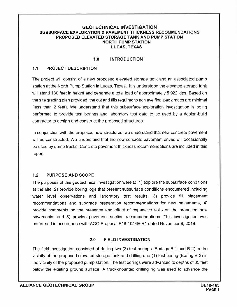


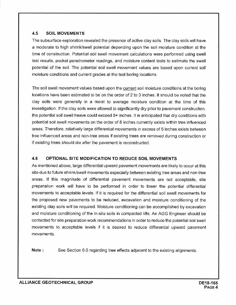
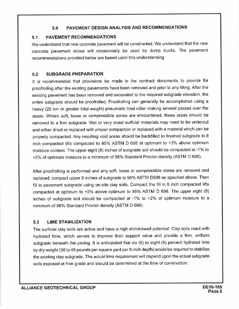

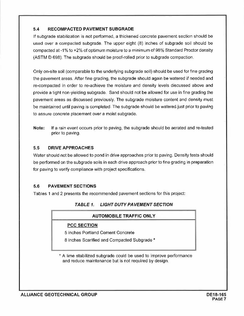
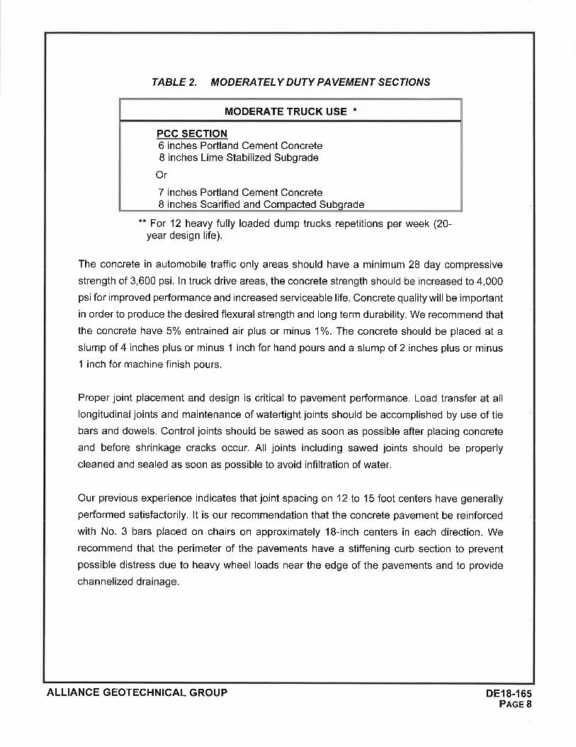
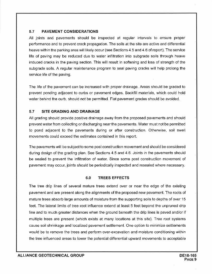


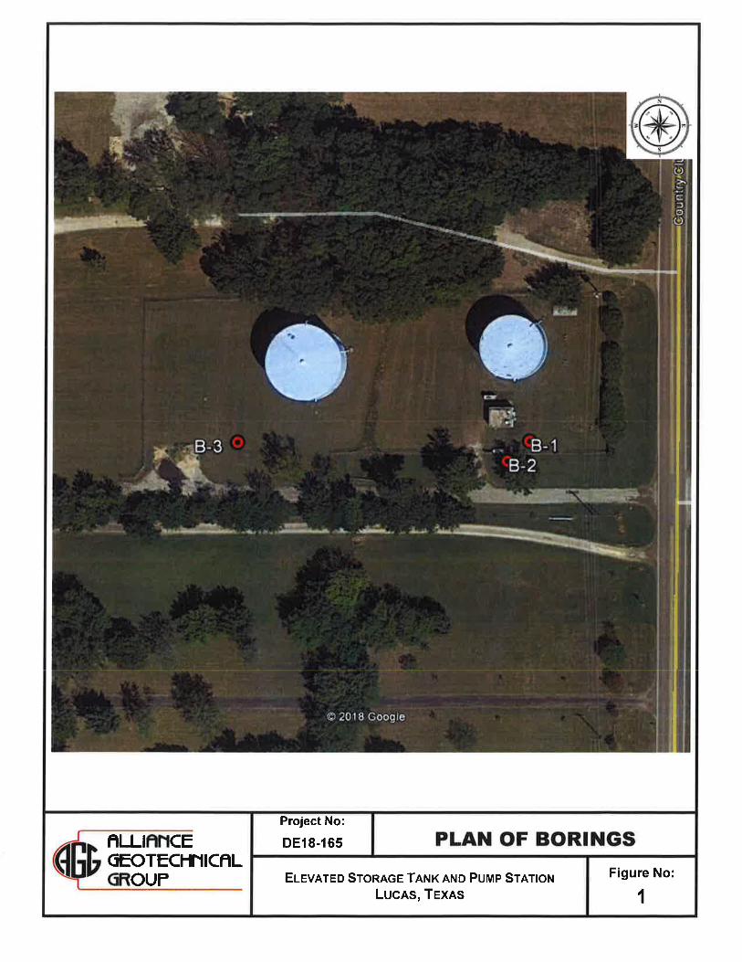
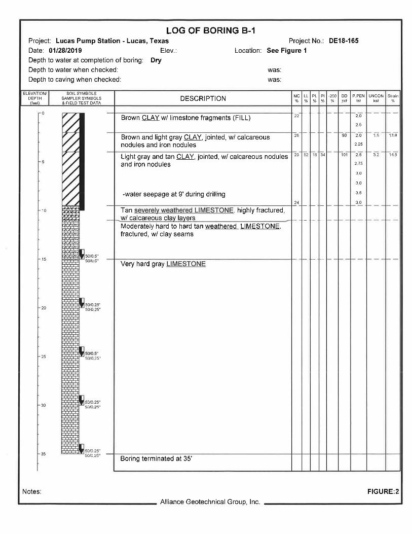

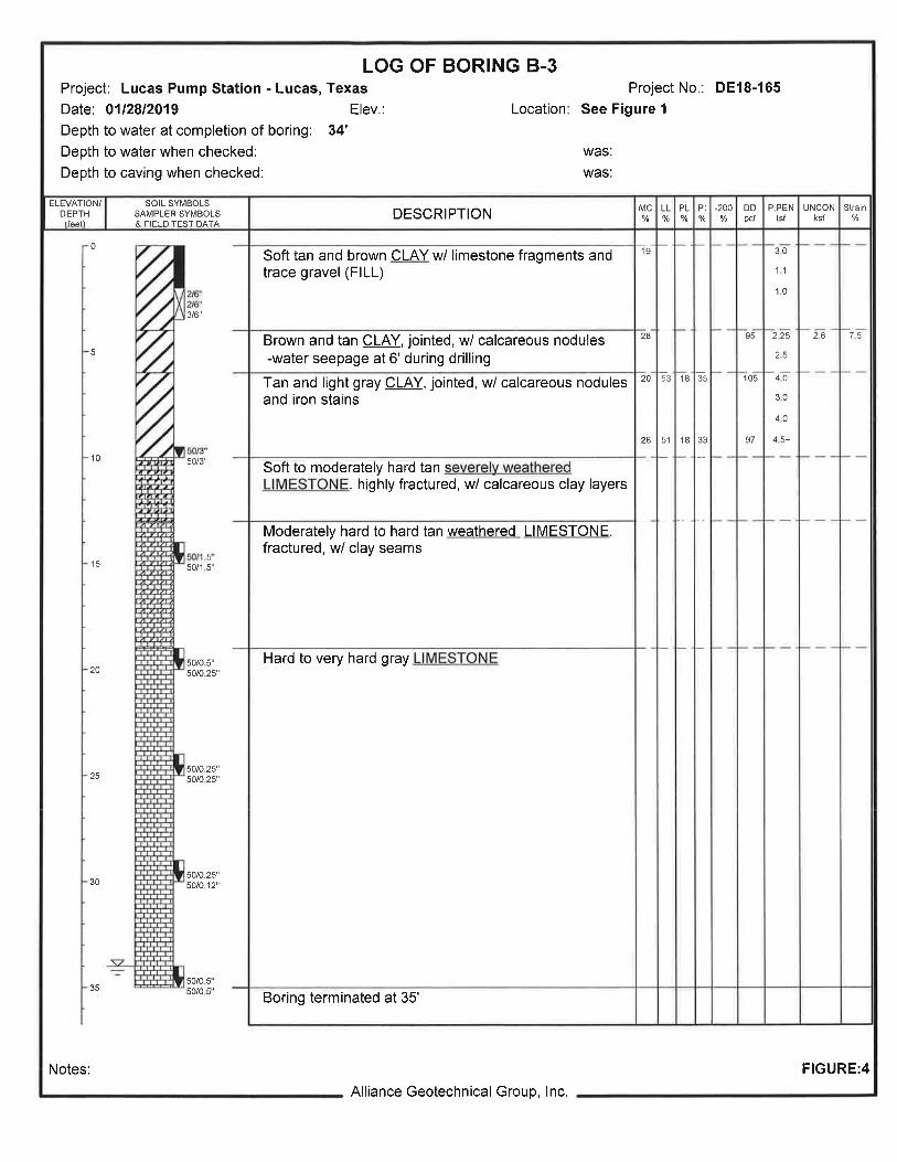
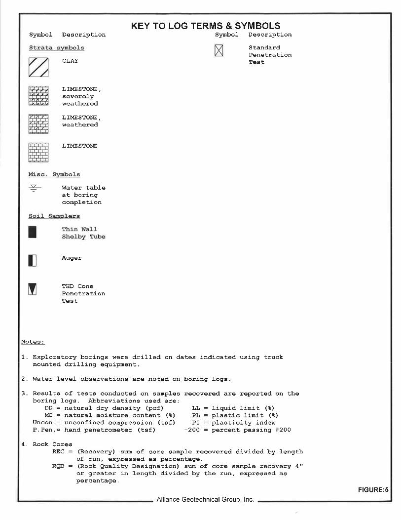


BIDDER’S QUALIFICATION STATEMENT

BIDDER’S QUALIFICATION STATEMENT
Project: Bid No.
Contractor:
Indicate One: Sole Proprietor Partnership Other
Corporation Joint Venture
Name: Partner:
Title: Title:
Address: Address:
City: City:
State & Zip: State & Zip:
Phone: Phone:
State and Date of Incorporation, Partnership, Ownership, Etc.
Location of Principal Office:
Contact and Phone at Principal Office:
Liability Insurance Provider and Limits of Coverage:
Workers compensation Insurance Provider:
Address:
Contact and Phone:
Number of Years in Business as a Contractor on Above Types of Work:
Claims and Suits (If the answer to any of the questions is yes, please attach details):
Has your organization ever failed to complete any work awarded to it?
Are there any judgments, claims, arbitration proceedings, or suits pending or outstanding against your organization or its officers?

Has your organization filed any lawsuits or requested arbitration with regard to construction contracts within the last five years?
Within the last five years, has any officer or principal of your organization ever been an officer or principal of another organization when it failed to complete a construction contract?
List your most current agreements/contracts, with information, similar to the type of work bid. (Use Additional Sheets if Necessary) Project: ______________________________________________________________ Project Description: ____________________________________________________ Owner/Agency: _______________________________________________________ Contract Price: __________________________ Contact Person: ______________ Phone: ______________Email_____________ Project: ______________________________________________________________ Project Description: ____________________________________________________ Owner/Agency: _______________________________________________________ Contract Price: __________________________ Contact Person: ______________ Phone: ______________Email______________ Project: ______________________________________________________________ Project Description: _____________________________________________________ Owner/Agency: ________________________________________________________ Contract Price: __________________________ Contact Person: ______________ Phone: ______________Email______________
Bank References (List Institution, Address, Contact Person, and Phone):

ADDENDA