Embed Size (px)
Citation preview


MD ANDERSON Project No. 11-0301 BASTROP BUILDING 302 ROOF REPLACEMENT Building Exterior Solutions, LLC Issued for Bid and Construction BES Project No. 5001 August 23, 2013
The University of Texas TABLE OF CONTENTS MD Anderson Cancer Center 00 01 10 MS022613 1 OF 5
PROJECT MANUAL TABLE OF CONTENTS
A – PROCUREMENT AND CONTRACTING REQUIREMENTS GROUP DIVISION 00 PROCUREMENT AND CONTRACTING REQUIREMENTS
2010 Uniform General and Supplementary General Conditions for University of Texas System Building Construction Contracts
00 25 00 Owners Special Conditions
00 25 00 A Attachment “A” - Minimum Wage Rate Determination
00 25 00 B Attachment “B” - Facilities Planned Utility Outages Policy
00 25 00 D Attachment “D” - Bastrop Visitation and Tour Policy Statement and Medical Documentation Requirements
B - SPECIFICATIONS GROUP
DIVISION 01 GENERAL REQUIREMENTS 01 31 00 Project Administration
01 32 00 Project Planning and Scheduling
01 35 16 Alteration Project Procedures
01 35 25 Owner Safety Requirements
01 35 25 A Attachment “A” - Maintaining Indoor Air Quality During Construction And Maintenance Activities Policy
01 45 00 Project Quality Control
01 77 00 Project Closeout Procedures
DIVISION 02 EXISTING CONDITIONS REVISION
02 41 19 Not Used DIVISION 03 CONCRETE REVISION 03 01 00 Maintenance of Concrete Roof Deck 03 01 40.51 Cleaning of Precast Concrete 03 01 40.71 Maintenance of Precast Concrete
DIVISION 04 MASONRY REVISION Not Used

MD ANDERSON Project No. 11-0301 BASTROP BUILDING 302 ROOF REPLACEMENT Building Exterior Solutions, LLC Issued for Bid and Construction BES Project No. 5001 August 23, 2013
The University of Texas TABLE OF CONTENTS MD Anderson Cancer Center 00 01 10 MS022613 2 OF 5
DIVISION 05 METALS REVISION 05 50 00 Metal Fabrications
DIVISION 06 WOOD, PLASTICS AND COMPOSITES REVISION 06 10 00 Rough Carpentry
DIVISION 07 THERMAL AND MOISTURE PROTECTION REVISION 07 01 50 Preparation For Re-Roofing
07 52 13 APP-Modified Bituminous Membrane Roofing
07 56 00 Fluid-Applied Elastomeric Wall Coatings 07 62 00 Sheet Metal Flashing and Trim
07 70 00 Roof Specialties and Accessories
07 92 00 Joint Sealants
DIVISION 08 OPENINGS REVISION Not Used
DIVISION 09 FINISHES REVISION Not Used
DIVISION 10 SPECIALTIES REVISION Not Used
DIVISION 11 EQUIPMENT REVISION
Not Used
DIVISION 12 FURNISHINGS REVISION
Not Used
DIVISION 13 SPECIAL CONSTRUCTION EQUIPMENT REVISION Not Used
DIVISION 14 CONVEYING EQUIPMENT REVISION
Not Used
MD ANDERSON Project No. 11-0301 BASTROP BUILDING 302 ROOF REPLACEMENT Building Exterior Solutions, LLC Issued for Bid and Construction BES Project No. 5001 August 23, 2013
The University of Texas TABLE OF CONTENTS MD Anderson Cancer Center 00 01 10 MS022613 3 OF 5
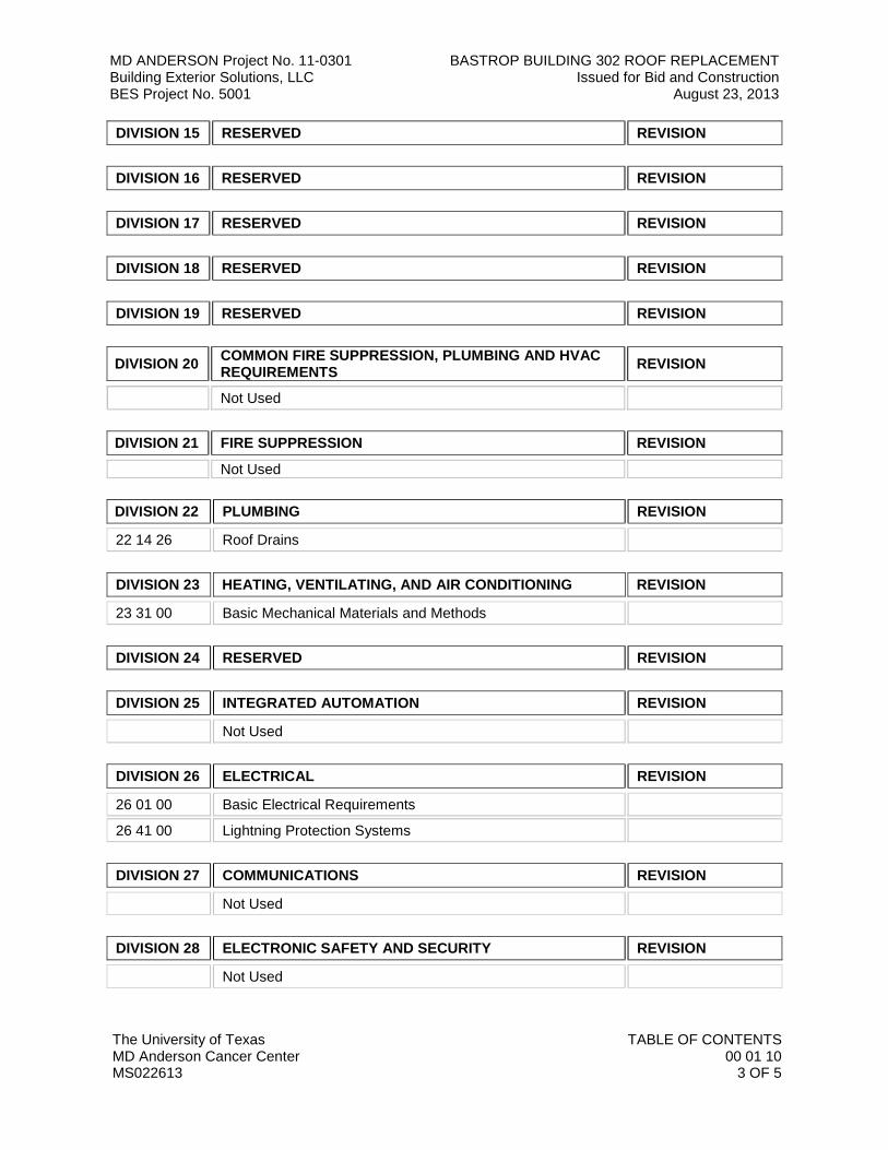
DIVISION 15 RESERVED REVISION
DIVISION 16 RESERVED REVISION
DIVISION 17 RESERVED REVISION
DIVISION 18 RESERVED REVISION
DIVISION 19 RESERVED REVISION
DIVISION 20 COMMON FIRE SUPPRESSION, PLUMBING AND HVAC REQUIREMENTS REVISION
Not Used
DIVISION 21 FIRE SUPPRESSION REVISION Not Used
DIVISION 22 PLUMBING REVISION 22 14 26 Roof Drains
DIVISION 23 HEATING, VENTILATING, AND AIR CONDITIONING REVISION 23 31 00 Basic Mechanical Materials and Methods
DIVISION 24 RESERVED REVISION
DIVISION 25 INTEGRATED AUTOMATION REVISION Not Used
DIVISION 26 ELECTRICAL REVISION 26 01 00 Basic Electrical Requirements
26 41 00 Lightning Protection Systems
DIVISION 27 COMMUNICATIONS REVISION Not Used
DIVISION 28 ELECTRONIC SAFETY AND SECURITY REVISION Not Used
MD ANDERSON Project No. 11-0301 BASTROP BUILDING 302 ROOF REPLACEMENT Building Exterior Solutions, LLC Issued for Bid and Construction BES Project No. 5001 August 23, 2013
The University of Texas TABLE OF CONTENTS MD Anderson Cancer Center 00 01 10 MS022613 4 OF 5
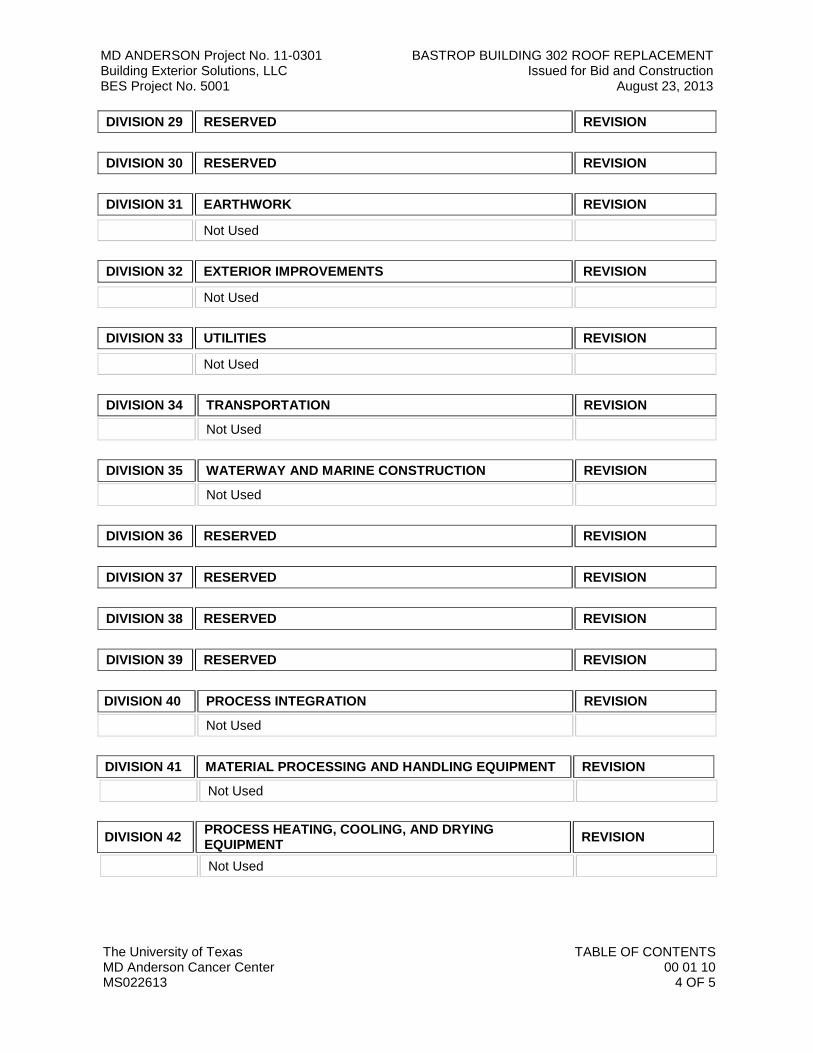
DIVISION 29 RESERVED REVISION
DIVISION 30 RESERVED REVISION
DIVISION 31 EARTHWORK REVISION Not Used
DIVISION 32 EXTERIOR IMPROVEMENTS REVISION Not Used
DIVISION 33 UTILITIES REVISION Not Used
DIVISION 34 TRANSPORTATION REVISION
Not Used
DIVISION 35 WATERWAY AND MARINE CONSTRUCTION REVISION
Not Used
DIVISION 36 RESERVED REVISION
DIVISION 37 RESERVED REVISION
DIVISION 38 RESERVED REVISION
DIVISION 39 RESERVED REVISION
DIVISION 40 PROCESS INTEGRATION REVISION
Not Used
DIVISION 41 MATERIAL PROCESSING AND HANDLING EQUIPMENT REVISION
Not Used
DIVISION 42 PROCESS HEATING, COOLING, AND DRYING EQUIPMENT REVISION
Not Used
MD ANDERSON Project No. 11-0301 BASTROP BUILDING 302 ROOF REPLACEMENT Building Exterior Solutions, LLC Issued for Bid and Construction BES Project No. 5001 August 23, 2013
The University of Texas TABLE OF CONTENTS MD Anderson Cancer Center 00 01 10 MS022613 5 OF 5
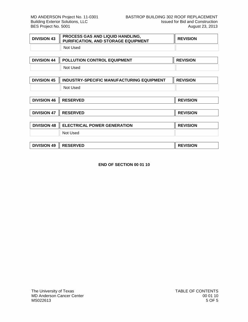
DIVISION 43 PROCESS GAS AND LIQUID HANDLING, PURIFICATION, AND STORAGE EQUIPMENT REVISION
Not Used
DIVISION 44 POLLUTION CONTROL EQUIPMENT REVISION
Not Used
DIVISION 45 INDUSTRY-SPECIFIC MANUFACTURING EQUIPMENT REVISION
Not Used
DIVISION 46 RESERVED REVISION
DIVISION 47 RESERVED REVISION
DIVISION 48 ELECTRICAL POWER GENERATION REVISION
Not Used
DIVISION 49 RESERVED REVISION
END OF SECTION 00 01 10

2010 Uniform General and Supplementary General Conditions
for
University of Texas System Building Construction Contracts
For use on all UT System and Institutional Construction Projects with a value ≥$100,000 that are executed on or after July 1, 2011
Table of Contents
Article 1. Definitions
Article 2. Wage Rates and Other Laws Governing Construction
Article 3. General Responsibilities of Owner and Contractor
Article 4. Historically Underutilized Business (HUB) Subcontracting Plan
Article 5. Bonds and Insurance
Article 6. Construction Documents, Coordination Documents, and Record Documents
Article 7. Construction Safety
Article 8. Quality Control
Article 9. Construction Schedules
Article 10. Payments
Article 11. Changes
Article 12. Project Completion and Acceptance
Article 13. Warranty and Guarantee
Article 14. Suspension and Termination
Article 15. Dispute Resolution
Article 16. Miscellaneous

2010 Uniform General and Supplementary Conditions for UT System Construction Projects
1
Article 1. Definitions Unless the context clearly requires another meaning, the following terms have the meaning assigned herein.
1.1 Application for Payment means Contractor’s monthly partial invoice for payment that includes any portion of the Work that has been completed for which an invoice has not been submitted and performed in accordance with the requirements of the Contract Documents. The Application for Payment accurately reflects the progress of the Work, is itemized based on the Schedule of Values, bears the notarized signature of Contractor, and shall not include subcontracted items for which Contractor does not intend to pay.
1.2 Application for Final Payment means Contractor’s final invoice for payment that includes any portion
of the Work that has been completed for which an invoice has not been submitted, amounts owing to adjustments to the final Contract Sum resulting from approved change orders, and release of remaining Contractor’s retainage.
1.3 Architect/Engineer (A/E) means a person registered as an architect pursuant to Tex. Occ. Code Ann.,
Chapter 1051, as a landscape architect pursuant to Tex. Occ. Code Ann., Chapter 1052, a person licensed as a professional engineer pursuant Tex. Occ. Code Ann., Chapter 1001, and/or a firm employed by Owner or Design-Build Contractor to provide professional architectural or engineering services and to exercise overall responsibility for the design of a Project or a significant portion thereof, and to perform the contract administration responsibilities set forth in the Contract.
1.4 Baseline Schedule means the initial time schedule prepared by Contractor for Owner’s information and
acceptance that conveys Contractor’s and Subcontractors’ activities (including coordination and review activities required in the Contract Documents to be performed by A/E and ODR), durations, and sequence of work related to the entire Project to the extent required by the Contract Documents. The schedule clearly demonstrates the critical path of activities, durations and necessary predecessor conditions that drive the end date of the schedule. The Baseline Schedule shall not exceed the time limit current under the Contract Documents.
1.5 Certificate of Final Completion means the certificate issued by A/E that documents, to the best of
A/E’s knowledge and understanding, Contractor’s completion of all Contractor’s Punchlist items and pre-final Punchlist items, final cleanup and Contractor’s provision of Record Documents, operations and maintenance manuals, and all other closeout Close-Out documents required by the Contract Documents.
1.6 Change Order means a written modification of the Contract between Owner and Contractor, signed by
Owner, Contractor and A/E. 1.7 Close-out Documents mean the product brochures, submittals, product/equipment maintenance and
operations instructions, manuals, and other documents/warranties, record documents, affidavit of payment, release of lien and claim, and as may be further defined, identified, and required by the Contract Documents.
1.8 Contract means the entire agreement between Owner and Contractor, including all of the Contract
Documents. 1.9 Contract Date is the date when the agreement between Owner and Contractor becomes effective. 1.10 Contract Documents mean those documents identified as a component of the agreement (Contract)
between Owner and Contractor. These may include, but are not limited to, Drawings; Specifications; General, Supplementary General, and Special Conditions; and all pre-bid and/or pre-proposal addenda.
1.11 Contract Sum means the total compensation payable to Contractor for completion of the Work in

2010 Uniform General and Supplementary Conditions for UT System Construction Projects
2
accordance with the terms of the Contract. 1.12 Contract Time means the period between the start date identified in the Notice to Proceed with
construction and the Substantial Completion date identified in the Notice to Proceed or as subsequently amended by a Change Order.
1.13 Contractor means the individual, corporation, limited liability company, partnership, firm, or other
entity contracted to perform the Work, regardless of the type of construction contract used, so that the term as used herein includes a Construction Manager-at-Risk or a Design-Build firm as well as a general or prime Contractor. The Contract Documents refer to Contractor as if singular in number.
1.14 Construction Documents mean the Drawings, Specifications, and other documents issued to build the
Project. Construction Documents become part of the Contract Documents when listed in the Contract or any Change Order.
1.15 Construction Manager-at-Risk, in accordance with Tex. Gov’t Code, Chapter 2166 Tex. Educ. Code §
51.782, means a sole proprietorship, partnership, corporation, or other legal entity that assumes the risk for construction, rehabilitation, alteration, or repair of a facility at the contracted price as a general contractor and provides consultation to Owner regarding construction during and after the design of the facility.
1.16 Date of Commencement means the date designated in the Notice to Proceed for Contractor to
commence the Work. 1.17 Day means a calendar day unless otherwise specifically stipulated. 1.18 Design-Build means a project delivery method in which the detailed design and subsequent
construction is provided through a single contract with a Design-Build firm; a team, partnership, or legal entity that includes design professionals and a builder. The Design-Build Project delivery shall be implemented in accordance with Tex. Gov’t Code § 2166.2531 Tex. Educ. Code § 51.780.
1.19 Drawings mean that product of A/E which graphically depicts the Work. 1.20 Final Completion means the date determined and certified by A/E and Owner on which the Work is
fully and satisfactorily complete in accordance with the Contract. 1.21 Final Payment means the last and final monetary compensation made to Contractor for any portion of
the Work that has been completed and accepted for which payment has not been made, amounts owing to adjustments to the final Contract Sum resulting from approved change orders, and release of Contractor’s retainage.
1.22 Historically Underutilized Business (HUB) pursuant to Tex. Gov’t Code, Chapter 2161, means a
business that is at least 51% owned by an Asian Pacific American, a Black American, a Hispanic American, a Native American and/or an American Woman; is an entity with its principal place of business in Texas; and has an owner residing in Texas with proportionate interest that actively participates in the control, operations, and management of the entity’s affairs.
1.23 Notice to Proceed means written document informing Contractor of the dates beginning Work and the
dates anticipated for Substantial Completion. 1.24 Open Item List means a list of work activities, Punchlist items, changes or other issues that are not
expected by Owner and Contractor to be complete prior to Substantial Completion. 1.25 Owner means the State of Texas, and any agency of the State of Texas, acting through the responsible
entity of the State of Texas identified in the Contract as Owner.

2010 Uniform General and Supplementary Conditions for UT System Construction Projects
3
1.26 Owner’s Designated Representative (ODR) means the individual assigned by Owner to act on its behalf and to undertake certain activities as specifically outlined in the Contract. ODR is the only party authorized to direct changes to the scope, cost, or time of the Contract.
1.27 Project means all activities necessary for realization of the Work Owner’s desired building or other
structure including all ancillary and related work. This includes design, contract award(s), execution of the Work itself, work by Owner’s forces and/or other contractors and fulfillment of all Contract and warranty obligations.
1.28 Progress Assessment Report (PAR) means the monthly compliance report to Owner verifying
compliance with the HUB subcontracting plan (HSP). 1.29 Proposed Change Order (PCO) means a document that informs Contractor of a proposed change in
the Work and appropriately describes or otherwise documents such change including Contractor’s response of pricing for the proposed change.
1.30 Punchlist means a list of items of Work to be completed or corrected by Contractor after Substantial
Completion before Final Completion. Punchlists indicate items to be finished, remaining Work to be performed, or Work that does not meet quality or quantity requirements as required in the Contract Documents.
1.31 Record Documents mean the drawing set, Specifications, and other materials maintained by Contractor
that documents all addenda, Architect’s Supplemental Instructions, Change Orders and postings and markings that record the as-constructed conditions of the Work and all changes made during construction.
1.32 Request for Information (RFI) means a written request by Contractor directed to A/E or ODR for a
clarification of the information provided in the Contract Documents or for direction concerning information necessary to perform the Work that may be omitted from the Contract Documents.
1.33 Samples mean representative physical examples of materials, equipment, or workmanship used to
confirm compliance with requirements and/or to establish standards for use in execution of the Work. 1.34 Schedule of Values means the detailed breakdown of the cost of the materials, labor, and equipment
necessary to accomplish the Work as described in the Contract Documents, submitted by Contractor for approval by Owner and A/E.
1.35 Shop Drawings mean the drawings, diagrams, illustrations, schedules, performance charts, brochures,
and other data prepared by Contractor or its agents which detail a portion of the Work. 1.36 Site means the geographical area of the location of the Work. 1.37 Special Conditions mean the documents containing terms and conditions which may be unique to the
Project. Special Conditions are a part of the Contract Documents and have precedence over the Uniform General Conditions and Supplementary General Conditions.
1.38 Specifications mean the written product of A/E that establishes the quality and/or performance of
products utilized in the Work and processes to be used, including testing and verification for producing the Work.
1.39 Subcontractor means a business entity that enters into an agreement with Contractor to perform part of
the Work or to provide services, materials, or equipment for use in the Work. 1.40 Submittal Register means a list provided by Contractor of all items to be furnished for review and
approval by A/E and Owner and as identified in the Contract Documents including anticipated sequence and submittal dates.

2010 Uniform General and Supplementary Conditions for UT System Construction Projects
4
1.41 Substantial Completion means the date determined and certified by Contractor, A/E, and Owner when
the Work, or a designated portion thereof, is sufficiently complete, in accordance with the Contract, so as to be operational and fit for the use intended.
1.42 Supplementary General Conditions mean procedures and requirements that modify the Uniform
General Conditions. Supplementary General Conditions, when used, have precedence over the Uniform General Conditions.
Note: The University of Texas System has adopted Uniform Supplementary General Conditions
(USGCs) that apply to all U.T. System and component institution construction projects. The USGCs are identified in this document as strikethroughs to the original text and/or as inserted text in the bold and italicized typeface shown here.
1.43 Unit Price Work means the Work, or a portion of the Work, paid for based on incremental units of
measurement. 1.44 Unilateral Change Order (ULCO) means a Change Order issued by Owner without the complete
agreement of Contractor, as to cost and/or time. 1.45 Work means the administration, procurement, materials, equipment, construction and all services
necessary for Contractor, and/or its agents, to fulfill Contractor’s obligations under the Contract. 1.46 Work Progress Schedule means the continually updated time schedule prepared and monitored by
Contractor that accurately indicates all necessary appropriate revisions as required by the conditions of the Work and the Project while maintaining a concise comparison to the Baseline Schedule.
Article 2. Wage Rates and Other Laws Governing Construction
2.1 Environmental Regulations. Contractor shall conduct activities in compliance with applicable laws and regulations and other requirements of the Contract relating to the environment and its protection at all times. Unless otherwise specifically determined, Owner is responsible for obtaining and maintaining permits related to stormwater run-off. Contractor shall conduct operations consistent with stormwater run-off permit conditions. Contractor is responsible for all items it brings to the Site, including hazardous materials, and all such items brought to the Site by its Subcontractors and suppliers, or by other entities subject to direction of Contractor. Contractor shall not incorporate hazardous materials into the Work without prior approval of Owner, and shall provide an affidavit attesting to such in association with request for Substantial Completion inspection.
2.2 Wage Rates. Contractor shall not pay less than the wage scale of the various classes of labor as shown
on the prevailing wage schedule provided by Owner in the bid or proposal specifications. The specified wage rates are minimum rates only. Owner is not bound to pay any claims for additional compensation made by any Contractor because the Contractor pays wages in excess of the applicable minimum rate contained in the Contract. The prevailing wage schedule is not a representation that qualified labor adequate to perform the Work is available locally at the prevailing wage rates.
2.2.1 Notification to Workers. Contractor shall post the prevailing wage schedule in a place
conspicuous to all workers on the Project Site and shall notify each worker, in writing, of the following as they commence work on the Contract: the worker’s job classification, the established minimum wage rate requirement for that classification, as well as the worker’s actual wage. The notice must be delivered to and signed in acknowledgement of receipt by the worker and must list both the wages and fringe benefits to be paid or furnished for each classification in which the worker is assigned duties. When requested by Owner, Contractor shall furnish evidence of compliance with the Texas Prevailing Wage Law and the addresses of all workers.

2010 Uniform General and Supplementary Conditions for UT System Construction Projects
5
2.2.1.1 Contractor shall submit a copy of each worker’s wage-rate notification to ODR
with the application for progress payment for the period during which the worker was engaged in activities on behalf of the Project.
2.2.1.2 The prevailing wage schedule is determined by Owner in compliance with Tex.
Gov’t Code, Chapter 2258. Should Contractor at any time become aware that a particular skill or trade not reflected on Owner’s prevailing wage schedule will be or is being employed in the Work, whether by Contractor or by Subcontractor, Contractor shall promptly inform ODR of the proposed wage to be paid for the skill along with a justification for same and ODR shall promptly concur with or reject the proposed wage and classification. Contractor is responsible for determining the most appropriate wage for a particular skill in relation to similar skills or trades identified on the prevailing wage schedule. In no case, shall any worker be paid less than the wage indicated for laborers.
2.2.2 Penalty for Violation. Contractor, and any Subcontractor, will pay to the State a penalty of
sixty dollars ($60) for each worker employed for each day, or portion thereof, that the worker is paid less than the wage rates stipulated in the prevailing wage schedule.
2.2.3 Complaints of Violations.
2.2.3.1 Owner’s Determination of Good Cause. Upon receipt of information concerning a
violation, Owner will conduct an investigation in accordance with Tex. Gov’t Code, Chapter 2258 and make an initial determination as to whether good cause exists that a violation occurred. Upon making a good cause finding, Owner will retain the full amounts claimed by the claimant or claimants as the difference between wages paid and wages due under the prevailing wage schedule and any supplements thereto, together with the applicable penalties, such amounts being subtracted from successive progress payments pending a final decision on the violation.
2.2.3.2 No Extension of Time. If Owner’s determination proves valid that good cause
existed to believe a violation had occurred, Contractor is not entitled to an extension of time for any delay arising directly or indirectly from the arbitration procedures.
2.3 Venue for Suits. The venue for any suit arising from the Contract will be in a court of competent
jurisdiction in Travis County, Texas, or as may otherwise be designated in the Supplementary General Conditions.
2.4 Licensing of Trades. Contractor shall comply with all applicable provisions of State law related to
license requirements for skilled tradesmen, contractors, suppliers and or laborers, as necessary to accomplish the Work. In the event Contractor, or one of its Subcontractors, loses its license during the term of performance of the Contract, Contractor shall promptly hire or contract with a licensed provider of the service at no additional cost to Owner.
2.5 Royalties, Patents, and Copyrights. Contractor shall pay all royalties and license fees, defend suits or
claims for infringement of copyrights and patent rights, and shall hold Owner harmless from loss on account thereof, but shall not be responsible for such defense or loss when a particular design, process or product of a particular manufacturer or manufacturers is required by the Contract Documents, or where the copyright violations are contained in Drawings, Specifications or other documents prepared by Owner or A/E. However, if Contractor has reason to believe that the required design, process, or product is an infringement of a copyright or a patent, Contractor shall be responsible for such loss unless such information is promptly furnished to A/E.
2010 Uniform General and Supplementary Conditions for UT System Construction Projects
6
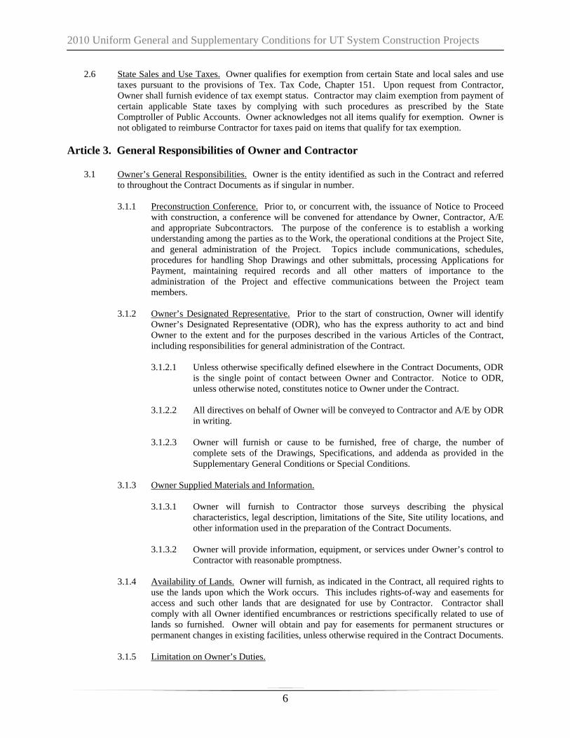
2.6 State Sales and Use Taxes. Owner qualifies for exemption from certain State and local sales and use taxes pursuant to the provisions of Tex. Tax Code, Chapter 151. Upon request from Contractor, Owner shall furnish evidence of tax exempt status. Contractor may claim exemption from payment of certain applicable State taxes by complying with such procedures as prescribed by the State Comptroller of Public Accounts. Owner acknowledges not all items qualify for exemption. Owner is not obligated to reimburse Contractor for taxes paid on items that qualify for tax exemption.
Article 3. General Responsibilities of Owner and Contractor
3.1 Owner’s General Responsibilities. Owner is the entity identified as such in the Contract and referred to throughout the Contract Documents as if singular in number.
3.1.1 Preconstruction Conference. Prior to, or concurrent with, the issuance of Notice to Proceed
with construction, a conference will be convened for attendance by Owner, Contractor, A/E and appropriate Subcontractors. The purpose of the conference is to establish a working understanding among the parties as to the Work, the operational conditions at the Project Site, and general administration of the Project. Topics include communications, schedules, procedures for handling Shop Drawings and other submittals, processing Applications for Payment, maintaining required records and all other matters of importance to the administration of the Project and effective communications between the Project team members.
3.1.2 Owner’s Designated Representative. Prior to the start of construction, Owner will identify
Owner’s Designated Representative (ODR), who has the express authority to act and bind Owner to the extent and for the purposes described in the various Articles of the Contract, including responsibilities for general administration of the Contract.
3.1.2.1 Unless otherwise specifically defined elsewhere in the Contract Documents, ODR
is the single point of contact between Owner and Contractor. Notice to ODR, unless otherwise noted, constitutes notice to Owner under the Contract.
3.1.2.2 All directives on behalf of Owner will be conveyed to Contractor and A/E by ODR
in writing.
3.1.2.3 Owner will furnish or cause to be furnished, free of charge, the number of complete sets of the Drawings, Specifications, and addenda as provided in the Supplementary General Conditions or Special Conditions.
3.1.3 Owner Supplied Materials and Information.
3.1.3.1 Owner will furnish to Contractor those surveys describing the physical
characteristics, legal description, limitations of the Site, Site utility locations, and other information used in the preparation of the Contract Documents.
3.1.3.2 Owner will provide information, equipment, or services under Owner’s control to
Contractor with reasonable promptness.
3.1.4 Availability of Lands. Owner will furnish, as indicated in the Contract, all required rights to use the lands upon which the Work occurs. This includes rights-of-way and easements for access and such other lands that are designated for use by Contractor. Contractor shall comply with all Owner identified encumbrances or restrictions specifically related to use of lands so furnished. Owner will obtain and pay for easements for permanent structures or permanent changes in existing facilities, unless otherwise required in the Contract Documents.
3.1.5 Limitation on Owner’s Duties.

2010 Uniform General and Supplementary Conditions for UT System Construction Projects
7
3.1.5.1 Owner will not supervise, direct, control or have authority over or be responsible for Contractor’s means, methods, technologies, sequences or procedures of construction or the safety precautions and programs incident thereto. Owner is not responsible for any failure of Contractor to comply with laws and regulations applicable to the Work. Owner is not responsible for the failure of Contractor to perform or furnish the Work in accordance with the Contract Documents. Except as provided in Section 2.5, Owner is not responsible for the acts or omissions of Contractor, or any of its Subcontractors, suppliers or of any other person or organization performing or furnishing any of the Work on behalf of Contractor.
3.1.5.2 Owner will not take any action in contravention of a design decision made by A/E
in preparation of the Contract Documents, when such actions are in conflict with statutes under which A/E is licensed for the protection of the public health and safety.
3.2 Role of Architect/Engineer. Unless specified otherwise in the Contract between Owner and
Contractor, A/E shall provide general administration services for Owner during the construction phase of the project. Written correspondence, requests for information, and Shop Drawings/submittals shall be directed to A/E for action. A/E has the authority to act on behalf of Owner to the extent provided in the Contract Documents, unless otherwise modified by written instrument, which will be furnished to Contractor by ODR, upon request.
3.2.1 Site Visits.
3.2.1.1 A/E will make visits to the Site at intervals as provided in the A/E’s Contract with
Owner, to observe the progress and the quality of the various aspects of Contractor’s executed Work and report findings to Owner.
3.2.1.2 A/E has the authority to interpret Contract Documents and inspect the Work for
compliance and conformance with the Contract. Except as referenced in Paragraph 3.1.5.2, Owner retains the sole authority to accept or reject Work and issue direction for correction, removal, or replacement of Work.
3.2.2 Clarifications and Interpretations. It may be determined that clarifications or interpretations
of the Contract Documents are necessary. Upon direction by ODR, such clarifications or interpretations will be provided by A/E consistent with the intent of the Contract Documents. A/E will issue these clarifications with reasonable promptness to Contractor as A/E’s supplemental instruction (“ASI”) or similar instrument. If Contractor believes that such clarification or interpretation justifies an adjustment in the Contract Sum or the Contract Time, Contractor shall so notify Owner in accordance with the provisions of Article 11.
3.2.3 Limitations on Architect/Engineer Authority. A/E is not responsible for:
3.2.3.1 Contractor’s means, methods, techniques, sequences, procedures, safety, or
programs incident to the Project, nor will A/E supervise, direct, control or have authority over the same;
3.2.3.2 The failure of Contractor to comply with laws and regulations applicable to the
furnishing or performing the Work;
3.2.3.3 Contractor’s failure to perform or furnish the Work in accordance with the Contract Documents; or
3.2.3.4 Acts or omissions of Contractor, or of any other person or organization performing
or furnishing any of the Work.

2010 Uniform General and Supplementary Conditions for UT System Construction Projects
8
3.3 Contractor’s General Responsibilities. Contractor is solely responsible for implementing the Work in full compliance with all applicable laws and the Contract Documents and shall supervise and direct the Work using the best skill and attention to assure that each element of the Work conforms to the Contract requirements. Contractor is solely responsible for all construction means, methods, techniques, safety, sequences, coordination and procedures.
Contractor shall visit the Site before commencing the Work and become familiar with local
conditions such as the location, accessibility and general character of the Site and/or building.
3.3.1 Project Administration. Contractor shall provide Project administration for all Subcontractors, vendors, suppliers, and others involved in implementing the Work and shall coordinate administration efforts with those of A/E and ODR in accordance with these general conditions, Division 1 of the Specifications and other provisions of the Contract, and as outlined in the pre-construction conference.
3.3.1.1 At the request of Owner and at no additional cost, Contractor shall furnish to
the ODR one copy of the current edition of the RSMeans Facilities Construction Cost Data Book in hard copy format or digital medium as directed by the ODR.
3.3.2 Contractor’s Management Personnel. Contractor shall employ a competent person or persons who will be present at the Project Site during the progress of the Work to supervise or oversee the work. The competent persons are subject to the approval of ODR. Contractor shall not change approved staff during the course of the project without the written approval of ODR unless the staff member leaves the employment of Contractor. Contractor shall provide additional quality control, safety and other staff as stated in the Supplementary General Conditions Contract Documents.
3.3.3 Labor. Contractor shall provide competent, suitably qualified personnel to survey, lay-out,
and construct the Work as required by the Contract Documents and maintain good discipline and order at the Site at all times.
3.3.4 Services, Materials, and Equipment. Unless otherwise specified, Contractor shall provide and
assume full responsibility for all services, materials, equipment, labor, transportation, construction equipment and machinery, tools, appliances, fuel, power, light, heat, telephone, water, sanitary facilities, temporary facilities, and all other facilities, incidentals, and services necessary for the construction, performance, testing, start-up, inspection and completion of the Work.
3.3.5 Contractor General Responsibility. For Owner furnished equipment or material that will be in
the care, custody, and control of Contractor, Contractor is responsible for damage or loss. 3.3.6 Non-Compliant Work. Should A/E and/or ODR identify Work as non-compliant with the
Contract Documents, A/E and/or ODR shall communicate the finding to Contractor, and Contractor shall correct such Work at no additional cost to the Owner. The approval of Work or the failure to find non‐compliant Work by either A/E or ODR does not relieve Contractor from the obligation to comply with all requirements of the Contract Documents.
3.3.7 Subcontractors. Contractor shall not employ any Subcontractor, supplier or other person or
organization, whether initially or as a substitute, against whom Owner shall have reasonable objection. Owner will communicate such objections in writing within ten (10) days of receipt of Contractor’s intent to use such Subcontractor, supplier, or other person or organization. Contractor is not required to employ any Subcontractor, supplier or other person or organization to furnish any of the work to whom Contractor has reasonable objection. Contractor shall not substitute Subcontractors without the acceptance of Owner.
2010 Uniform General and Supplementary Conditions for UT System Construction Projects
9
3.3.7.1 All Subcontracts and supply contracts shall be consistent with and bind the
Subcontractors and suppliers to the terms and conditions of the Contract Documents including provisions of the Contract between Contractor and Owner.
3.3.7.2 Contractor shall be solely responsible for scheduling and coordinating the Work of
Subcontractors, suppliers and other persons and organizations performing or furnishing any of the Work under a direct or indirect contract with Contractor. Require all Subcontractors, suppliers and such other persons and organizations performing or furnishing any of the Work to communicate with Owner only through Contractor. Contractor shall furnish to Owner a copy, at Owner’s request, of each first-tier subcontract promptly after its execution. Contractor agrees that Owner has no obligation to review or approve the content of such contracts and that providing Owner such copies in no way relieves Contractor of any of the terms and conditions of the Contract, including, without limitation, any provisions of the Contract which require the Subcontractor to be bound to Contractor in the same manner in which Contractor is bound to Owner.
3.3.8 Continuing the Work. Contractor shall carry on the Work and adhere to the progress schedule
during all disputes, disagreements, or alternative resolution processes with Owner. Contractor shall not delay or postpone any Work because of pending unresolved disputes, disagreements or alternative resolution processes, except as Owner and Contractor may agree in writing.
3.3.9 Cleaning. Contractor shall at all times, keep the Site and the Work clean and free from
accumulation of waste materials or rubbish caused by the construction activities under the Contract. Contractor shall ensure that the entire Project is thoroughly cleaned prior to requesting Substantial Completion inspection and, again, upon completion of the Project prior to the final inspection.
3.3.10 Acts and Omissions of Contractor, its Subcontractors and Employees. Contractor shall be
responsible for acts and omissions of his employees and all its Subcontractors, their agents and employees. Owner may, in writing, require Contractor to remove from the Project any of Contractor’s or its Subcontractor’s employees whom ODR finds to be careless, incompetent, unsafe, uncooperative, disruptive, or otherwise objectionable.
3.3.11 Indemnification of Owner. Contractor covenants and agrees to FULLY INDEMNIFY
and HOLD HARMLESS, Owner and the elected and appointed officials, employees, officers, directors, volunteers, and representatives of Owner, individually or collectively, from and against any and all costs, claims, liens, damages, losses, expenses, fees, fines, penalties, proceedings, actions, demands, causes of action, liability and suits of any kind and nature, including but not limited to, personal or bodily injury, death or property damage, made upon Owner directly or indirectly arising out of, resulting from or related to Contractor’s activities under this Contract, including any acts or omissions of Contractor, or any agent, officer, director, representative, employee, consultant or the Subcontractor of Contractor, and their respective officers, agents, employees, directors and representatives while in the exercise of performance of the rights or duties under this Contract. The indemnity provided for in this paragraph does not apply to any liability resulting from the negligence of the Owner, its officers or employees, separate contractors or assigned contractors, in instances where such negligence causes personal injury, death or property damage. IN THE EVENT CONTRACTOR AND OWNER ARE FOUND JOINTLY LIABLE BY A COURT OF COMPETENT JURISDICTION, LIABILITY WILL BE APPORTIONED COMPARATIVELY IN ACCORDANCE WITH THE LAWS OF THE STATE OF TEXAS, WITHOUT WAIVING ANY GOVERNMENTAL IMMUNITY AVAILABLE TO THE STATE UNDER TEXAS LAW AND WITHOUT WAIVING ANY DEFENSES OF THE PARTIES UNDER TEXAS LAW.

2010 Uniform General and Supplementary Conditions for UT System Construction Projects
10
3.3.11.1 The provisions of this indemnification are solely for the benefit of the parties
hereto and not intended to create or grant any rights, contractual or otherwise, to any other person or entity.
3.3.11.2 Contractor shall promptly advise Owner in writing of any claim or demand against
Owner or against Contractor which involves Owner and known to Contractor and related to or arising out of Contractor’s activities under this Contract.
3.3.12 Ancillary Areas. Contractor shall operate and maintain operations and associated storage
areas at the site of the Work in accordance with the following:
3.3.12.1 Confine All Contractor operations, including storage of materials and employee parking upon the Site of Work, shall be confined to areas designated by Owner.
3.3.12.2 Contractor may erect, at its own expense, temporary buildings that will remain its
property. Contractor shall remove such buildings and associated utility service lines upon completion of the Work, unless Contractor requests and Owner provides written consent that it may abandon such buildings and utilities in place.
3.3.12.3 Contractor shall use only established roadways or construct and use such
temporary roadways as may be authorized by Owner. Contractor shall not allow load limits of vehicles to exceed the limits prescribed by appropriate regulations or law. Contractor shall provide protection to road surfaces, curbs, sidewalks, trees, shrubbery, sprinkler systems, drainage structures and other like existing improvements to prevent damage and repair any damage thereto at the expense of Contractor.
3.3.12.4 Owner may restrict Contractor’s entry to the Site to specifically assigned entrances
and routes.
3.3.13 Separate Contracts. Owner reserves the right to award other contracts in connection with other portions of the Project under these the same or substantially similar contract conditions terms, including those portions related to insurance and waiver of subrogation. Owner reserves the right to perform operations related to the Project with Owner’s own forces.
3.3.14 Under a system of separate contracts, the conditions described herein continue to apply except
as may be amended by change order. 3.3.15 Contractor shall cooperate with other contractors or forces employed on the Project by
Owner, including providing access to Site, integration of activities within Contractor’s Work Progress Schedule and Project information as requested.
3.3.16 Owner shall be reimbursed by Contractor for costs incurred by Owner which are payable to a
separate contractor because of delays, improperly timed activities, or defective construction by Contractor. Owner will equitably adjust the Contract by Change Order for costs incurred by Contractor because of delays, improperly timed activities, damage to the Work or defective construction by a separate contractor.
Article 4. Historically Underutilized Business (HUB) Subcontracting Plan
4.1 General Description. The purpose of the Historically Underutilized Business (HUB) program is to promote equal business opportunities for economically disadvantaged persons (as defined by Tex. Gov’t Code, Chapter 2161) to contract with the State of Texas in accordance with the goals specified in the State of Texas Disparity Study. The HUB program annual procurement utilization goals are

2010 Uniform General and Supplementary Conditions for UT System Construction Projects
11
defined in 34 T.A.C. § 20.13(b).
4.1.1 State agencies are required by statute to make a good faith effort to assist HUBs in participating in contract awards issued by the State. 34 T.A.C. § 20.13(b) outlines the State’s policy to encourage the utilization of HUBs in State contracting opportunities through race, ethnic and gender neutral means.
4.1.2 A Contractor who contracts with the State in an amount of $100,000 or greater is required to
make a good faith effort to award subcontracts to HUBs in accordance with 34 T.A.C. § 20.14(a)(2)(A) by submitting a HUB subcontracting plan within twenty-four (24) hours after the bid or response is due and complying with the HUB subcontracting plan after it is accepted by Owner and during the term of the Contract.
4.2 Compliance with Approved HUB Subcontracting Plan. Contractor, having been awarded this Contract
in part by complying with the HUB program statute and rules, hereby covenants to continue to comply with the HUB program as follows:
4.2.1 Prior to adding or substituting a Subcontractor, promptly notify Owner in the event a change
is required for any reason to the accepted HUB subcontracting plan.
4.2.2 Conduct the good-faith effort activities required and provide Owner with necessary documentation to justify approval of a change to the approved HUB subcontracting plan.
4.2.3 Cooperate in the execution of a Change Order or such other approval of the change in the
HUB subcontracting plans as Contractor and Owner may agree to. 4.2.4 Maintain and make available to Owner upon request business records documenting
compliance with the accepted HUB subcontracting plan. 4.2.5 Upon receipt of payment for performance of Work, submit to Owner a compliance report, in
the format required by Owner that demonstrates Contractor’s performance of the HUB subcontracting plan.
4.2.5.1 Progress Assessment Report (PAR): monthly compliance reports to Owner
(contracting agency), verifying their compliance with the HUB subcontracting plan, including the use/expenditures they have made to Subcontractors. (The PAR is available at http://www.window.state.tx.us/procurement/prog/hub/hub-forms/progressassessmentrpt.xls).
4.2.6 Promptly and accurately explain and provide supplemental information to Owner to assist in Owner’s investigation of Contractor’s good-faith effort to fulfill the HUB subcontracting plan and the requirements under 34 T.A.C. § 20.14(a)(1).
4.3 Failure to Demonstrate Good-Faith Effort. Upon a determination by Owner that Contractor has failed
to demonstrate a good-faith effort to fulfill the HUB subcontracting plan or any Contract covenant detailed above, Owner may, in addition to all other remedies available to it, report the failure to perform to the Comptroller of Public Accounts, Texas Procurement and Support Services Division, Historically Underutilized Business Program and may bar Contractor from future contracting opportunities with Owner.
Article 5. Bonds and Insurance
5.1 Construction Bonds. Contractor is required to tender to Owner, prior to commencing the Work, performance and payment bonds, as required by Tex. Gov’t Code, Chapter 2253. On Construction

2010 Uniform General and Supplementary Conditions for UT System Construction Projects
12
Manager-at-Risk and Design-Build Projects the Owner shall require a security bond, as described in Subsection 5.1.2 below.
5.1.1 Bond Requirements. Each bond shall be executed by a corporate surety or sureties authorized
to do business in the State of Texas and acceptable to Owner, on Owner’s form, and in compliance with the relevant provisions of the Texas Insurance Code. If any bond is for more than ten (10) percent of the surety’s capital and surplus, Owner may require certification that the company has reinsured the excess portion with one or more reinsurers authorized to do business in the State. A reinsurer may not reinsure for more than ten (10) percent of its capital and surplus. If a surety upon a bond loses its authority to do business in the State, Contractor shall, within thirty (30) days after such loss, furnish a replacement bond at no added cost to Owner.
5.1.1.1 A Performance bond is required if the Contract Sum is in excess of $100,000. The
performance bond is solely for the protection of Owner. The performance bond is to be for the Contract Sum to guarantee the faithful performance of the Work in accordance with the Contract Documents. The form of the bond shall be approved by the Office of the Attorney General of Texas. The performance bond shall be effective through Contractor’s warranty period.
5.1.1.2 A Payment bond is required if the Contract price is in excess of $25,000. The
payment bond is to be for the Contract Sum and is payable to Owner solely for the protection and use of payment bond beneficiaries. The form of the bond shall be approved by the Office of the Attorney General of Texas.
5.1.2 Security Bond. The security bond provides protection to Owner if Contractor presents an
acceptable guaranteed maximum price (“GMP”) to Owner and 1) fails to execute the GMP; or 2) fails but is unable to deliver the required payment and performance bonds within the time period stated below.
5.1.3 When Bonds Are Due
5.1.3.1 Security bonds are due within ten (10) days of signing before execution of a
Construction Manager-at-Risk or Design-Build Contract.
5.1.3.2 Payment and performance bonds are due before execution of a contract on competitively bid or competitively sealed proposal projects or before execution of a GMP proposal on Construction Manager‐at‐Risk projects or Design‐Build projects within ten (10) days of Contractor’s receipt of a fully executed GMP on a Construction Manager-at-Risk project or the Contract Sum for a Design-Build project, or within ten (10) days of Contractor’s receipt of a fully executed Contract on competitively bid or competitive sealed proposal projects.
5.1.4 Power of Attorney. Each bond shall be accompanied by a valid power of attorney (issued by
the surety company and attached, signed and sealed with the corporate embossed seal, to the bond) authorizing the attorney-in-fact who signs the bond to commit the company to the terms of the bond, and stating any limit in the amount for which the attorney can issue a single bond.
5.1.5 Bond Indemnification. The process of requiring and accepting bonds and making claims
thereunder shall be conducted in compliance with Tex. Gov’t Code, Chapter 2253. IF FOR ANY REASON A STATUTORY PAYMENT OR PERFORMANCE BOND IS NOT HONORED BY THE SURETY, CONTRACTOR SHALL FULLY INDEMNIFY AND HOLD OWNER HARMLESS OF AND FROM ANY COSTS, LOSSES, OBLIGATIONS OR LIABILITIES IT INCURS AS A RESULT.

2010 Uniform General and Supplementary Conditions for UT System Construction Projects
13
5.1.6 Furnishing Bond Information. Owner shall furnish certified copies of the payment bond and the related Contract to any qualified person seeking copies who complies with Tex. Gov’t Code § 2253.026.
5.1.7 Claims on Payment Bonds. Claims on payment bonds must be sent directly to Contractor and
his surety in accordance with Tex. Gov’t Code § 2253.041. All payment bond claimants are cautioned that no lien exists on the funds unpaid to Contractor on such Contract, and that reliance on notices sent to Owner may result in loss of their rights against Contractor and/or his surety. Owner is not responsible in any manner to a claimant for collection of unpaid bills, and accepts no such responsibility because of any representation by any agent or employee.
5.1.8 Payment Claims when Payment Bond not Required. The rights of Subcontractors regarding
payment are governed by Tex. Prop. Code §§ 53.231 – 53.239 when the value of the Contract between Owner and Contractor is less than $25,000.00. These provisions set out the requirements for filing a valid lien on funds unpaid to Contractor as of the time of filing the claim, actions necessary to release the lien and satisfaction of such claim.
5.1.9 Sureties. A surety shall be listed on the US Department of the Treasury’s Listing of
Approved Sureties maintained by the Bureau of Financial Management Service (FMS), www.fms.treas.gov/c570, stating companies holding Certificates of Authority as acceptable sureties on Federal bonds and acceptable reinsuring companies (FMS Circular 570).
5.2 Insurance Requirements. Contractor shall carry insurance in the types and amounts indicated in this
Article for the duration of the Contract. The required insurance shall include coverage for Owner’s property prior to construction, during construction and during the warranty period. The insurance shall be evidenced by delivery to Owner of certificates of insurance executed by the insurer or its authorized agent stating coverages, limits, expiration dates and compliance with all applicable required provisions. Upon request, Owner, and/or its agents, shall be entitled to receive without expense, copies of the policies and all endorsements. Contractor shall update all expired policies prior to submission for monthly payment. Failure to update policies shall be reason for withholding of payment until renewal is provided to Owner.
5.2.1 Contractor, consistent with its status as an independent contractor, shall provide and
maintain all insurance coverage with the minimum amounts described below until the end of the warranty period unless otherwise stated in Owner’s Supplementary General Conditions or Special Conditions. Failure to maintain insurance coverage, as required, is grounds for suspension of Work for cause pursuant to Article 14. The Contractor will be notified of the date on which the Builder’s Risk insurance policy may be terminated by any means deemed appropriate by Owner.
5.2.2 Coverage shall be written on an occurrence basis by companies authorized and admitted to do
business in the State of Texas and rated A-, VII or better by A.M. Best Company or similar rating company or otherwise acceptable to Owner.
5.2.2.1 Insurance Coverage Required.
5.2.2.1.1 Workers’ Compensation. Insurance with limits as required by the
Texas Workers’ Compensation Act, with the policy endorsed to provide a waiver of subrogation as to Owner, employer’s liability and Employer’s Liability Insurance with limits of not less than:
$100,000 $1,000,000 each accident;
$100,000 $1,000,000 disease each employee ; and

2010 Uniform General and Supplementary Conditions for UT System Construction Projects
14
$500,000 $1,000,000 disease policy limit. Policies must include (a) Other States Endorsement to include TEXAS if business is domiciled outside the State of Texas, and (b) a waiver of all rights of subrogation in favor of Owner.
5.2.2.1.2 Commercial General Liability Insurance, including premises,
operations, independent contractor’s liability, products and completed operations and contractual liability, covering, but not limited to, the liability assumed under the indemnification provisions of this Contract, fully insuring Contractor’s (or Subcontractor’s) liability for bodily injury (including death) and property damage with a minimum limit of:
$1,000,000 per occurrence;
$2,000,000 general aggregate;
$2,000,000 products and completed operations aggregate; and
Coverage shall be on an “occurrence” basis.
The policy shall include coverage extended to apply to completed operations and explosion, collapse, and underground hazards. The policy shall include endorsement CG2503 Amendment of Aggregate Limits of Insurance (per Project) or its equivalent.
If the Work involves any activities within fifty (50) feet of any railroad, railroad protective insurance as may be required by the affected railroad, written for not less than the limits required by such railroad.
5.2.2.1.3 Asbestos Abatement Liability Insurance, including coverage for
liability arising from the encapsulation, removal, handling, storage, transportation, and disposal of asbestos containing materials. *This requirement applies if the Work or the Project includes asbestos containing materials.
The combined single limit for bodily injury and property damage will be a minimum of $1,000,000 per occurrence.
*Specific requirement for claims-made form: Required period of coverage will be determined by the following formula: continuous coverage for life of the Contract, plus one (1) year (to provide coverage for the warranty period), and an extended discovery period for a minimum of five (5) years which shall begin at the end of the warranty period.
Employer’s liability limits for asbestos abatement will be:
$500,000 $1,000,000 each accident;
$500,000 $1,000,000 disease each employee; and
$500,000 $1,000,000 disease policy limit.

2010 Uniform General and Supplementary Conditions for UT System Construction Projects
15
If this Contract is for asbestos abatement only, the All-Risk Builder’s Risk or all-risk installation floater (5.2.2.1.5.e) is not required.
5.2.2.1.4 Comprehensive Business Automobile Liability Insurance, covering
all owned, hired, and non-owned vehicles, with a minimum combined single limit for bodily injury (including death) and property damage of $1,000,000 per occurrence. No aggregate shall be permitted for this type of coverage.
Such insurance is to include coverage for loading and unloading hazards.
5.2.2.1.5 All-Risk Builder’s Risk Insurance, if applicable (or all-risk
installation floater for instances in which the project involves solely the installation of material and/or equipment). Coverage is determined by the Contract Sum, as detailed, below.
Coverage shall be all-risk, including, but not limited to, fire, extended coverage, vandalism and malicious mischief, theft and, if applicable, flood, earth movement and named storm. Builder’s risk and installation floater limits shall be equal to 100 percent of the Contract Sum plus, if any, existing property and Owner-furnished equipment specified by Owner. The policy shall be written jointly in the names of Owner and Contractor. Subcontractors shall be named as additional insureds. The policy shall have endorsements as follows: 5.2.2.1.5.1 This insurance shall be specific as to coverage and not contributing insurance with any permanent
insurance maintained on the property.
5.2.2.1.5.2 This insurance shall not contain an occupancy clause suspending or reducing coverage should Owner partially occupy the Site and before the parties have determined Substantial Completion.
5.2.2.1.5.3 Loss, if any, shall be adjusted with and made payable to Owner as trustee for the insureds as their
interests may appear. Owner shall be named as loss payee.
5.2.2.1.5.4 For renovation projects or projects that involve portions of Work contained within an existing structure, refer to Supplementary General and Special Conditions for possible additional builder’s risk insurance requirements.
5.2.2.1.5.5 For Owner furnished equipment or materials that will be in care, custody or control of Contractor,
Contractor will be responsible for damage and loss.
5.2.2.1.5.6 For those properties located within a Tier 1 or 2 windstorm area, named storm coverage must be provided with limits specified by Owner.
5.2.2.1.5.7 For those properties located in flood prone areas, flood insurance coverage must be provided with
limits specified by Owner.
5.2.2.1.5.8 Builder’s risk insurance policy shall remain in effect until Substantial Completion.
BUILDERS RISK REQUIREMENT FOR PROJECTS WITH A CONTRACT SUM <$20 MILLION 5.2.2.1.5.1 Contractor shall purchase and maintain in force builders risk insurance on the entire Work.
Such insurance shall be written in the amount of the original contract, plus any subsequent change orders and plus the cost of materials supplied or installed by others, comprising Total Value for the entire Project at the site. The insurance shall apply on a replacement cost basis with no coinsurance provision. A sublimit may be applicable to flood coverage, but sublimit

2010 Uniform General and Supplementary Conditions for UT System Construction Projects
16
must be at least 20% of the Total Value of the Project. The limit for all other perils, including Named Windstorm, Wind, and Hail, must be equal to the Total Value for the entire Project at the site. (If Installation Floater, limit shall be equal to 100 percent of the contract cost.)
5.2.2.1.5.2 This insurance shall name as insureds the Owner, the Contractor, and all subcontractors and
sub‐subcontractors in the Work. 5.2.2.1.5.3 Builders risk insurance shall be on an “all risk” or equivalent policy form and shall include,
without limitation, insurance against fire and extended coverage perils, theft, vandalism, malicious mischief, collapse, earthquake, flood, windstorm, boiler and machinery/mechanical breakdown, testing and startup, and terrorism.
5.2.2.1.5.4 This insurance shall cover the entire work at the site as required in 5.2.2.1.5.1, including, but not
limited to, the following:
• Temporary works including but not limited to scaffolding, form work, fences, shoring, hoarding, falsework and temporary buildings
• Offsite Storage • Portions of the work in transit • Debris removal • Extra Expense • Expediting Expenses • Demolition and Increased Cost of Construction • Pollutant Clean‐Up and Removal • Trees, Shrubs, Plants, Lawns and Landscaping (if applicable) • Errors & Omissions (applicable to purchase of Builders Risk policy only)
5.2.2.1.5.5 This insurance shall not contain an occupancy clause suspending or reducing coverage should the Owner occupy, or begin beneficial occupancy before the Owner has accepted final completion.
5.2.2.1.5.6 This insurance shall be specific as to coverage and shall be primary to any permanent insurance
or self‐insurance that may be maintained on the property by Owner. 5.2.2.1.5.7 This insurance shall include a waiver of subrogation in favor of Owner, the Contractor, and all
subcontractors and sub‐subcontractors in the work. 5.2.2.1.5.8 As applicable, Flood deductible shall not exceed $250,000 for Zone A, $100,000 for Zone B and
$50,000 for all other Zones. For Tier 1 and Tier 2, Named Windstorm deductible shall not exceed 2% of the project values in place at the time of the loss.
5.2.2.1.5.9 Before the commencement of the work, Contractor shall provide to Owner an accurate
certificate of insurance that provides specific evidence of all requirements outlined in Section 5.2.2.1.5. A copy of the policy itself shall be provided to Owner within 30 days after Notice to Proceed.
5.2.2.1.5.10 Refer to Owner’s Special Conditions for possible additional Builders Risk insurance
requirements. BUILDERS RISK REQUIREMENT FOR PROJECTS WITH A CONTRACT SUM ≥$20 MILLION 5.2.2.1.5.1 Contractor shall purchase and maintain in force builders risk insurance on the entire Work.

2010 Uniform General and Supplementary Conditions for UT System Construction Projects
17
Such insurance shall be written in the amount of the original contract, plus any subsequent change orders and plus the cost of materials supplied or installed by others, comprising Total Value for the entire Project at the site. The insurance shall apply on a replacement cost basis with no coinsurance provision and shall include a margin clause of plus/minus 10% on project value. A sublimit may be applicable to flood coverage, but sublimit must be at least 20% of the Total Value of the Project. A sublimit of $50 million or the Total Value of the Project, whichever is less, is acceptable for Earthquake. The limit for all other perils, including Named Windstorm, Wind, and Hail, must be equal to the Total Value for the entire Project at the site. (If Installation Floater, limit shall be equal to 100 percent of the contract cost.)
5.2.2.1.5.2 This insurance shall name as insureds the Owner, the Contractor, and all subcontractors and
sub‐subcontractors in the Work. 5.2.2.1.5.3 Builders risk insurance shall be on an “all risk” or equivalent policy form and shall include,
without limitation, insurance against fire and extended coverage perils, theft, vandalism, malicious mischief, collapse, earthquake, flood, windstorm, boiler and machinery/mechanical breakdown, testing and startup, and terrorism.
5.2.2.1.5.4 This insurance shall cover the entire work at the site as required in 5.2.2.1.5.1, including, but
not limited to, the following: Coverage Minimum Limit Required Temporary works including but not limited to scaffolding, form work, fences, shoring, hoarding, falsework and temporary buildings
$1 million
Offsite Storage Sufficient to cover the anticipated maximum values stored offsite
Portions of the work in Transit Sufficient to cover the anticipated maximum values in transit
Debris Removal 25% of Physical damage amount subject to maximum of $5 million or 25% of Total Value of Project whichever is higher
Expediting Expenses $1 millionExtra Expense $5 millionDemolition and Increased Cost of Construction $2 million or 10% of Total Value of Project whichever is
higher Pollutant Clean‐Up and Removal $250,000Trees, Shrubs, Plants, Lawns and Landscaping (if applicable)
$2,500 per item subject to a maximum of $1 million
Errors & Omissions (applicable to purchase of Builders Risk policy only)
$2.5 million
5.2.2.1.5.5 This insurance shall not contain an occupancy clause suspending or reducing coverage should
the Owner occupy, or begin beneficial occupancy before the Owner has accepted final completion.
5.2.2.1.5.6 This insurance shall be specific as to coverage and shall be primary to any permanent insurance
or self‐insurance that may be maintained on the property by Owner. 5.2.2.1.5.7 This insurance shall include a waiver of subrogation in favor of Owner, the Contractor, and all
subcontractors and sub‐subcontractors in the work. 5.2.2.1.5.8 As applicable, Flood deductible shall not exceed $250,000 for Zone A, $100,000 for Zone B and

2010 Uniform General and Supplementary Conditions for UT System Construction Projects
18
$50,000 for all other Zones. For Tier 1 and Tier 2, Named Windstorm deductible shall not exceed 2% of the project values in place at the time of the loss.
5.2.2.1.5.9 Before the commencement of the work, Contractor shall provide to Owner an accurate
certificate of insurance that provides specific evidence of all requirements outlined in Section 5.2.2.1.5. A copy of the policy itself shall be provided to Owner within 30 days after Notice to Proceed.
5.2.2.1.5.10 Refer to Owner’s Special Conditions for possible additional Builders Risk insurance requirements.
5.2.2.1.6 “Umbrella” Liability Insurance. Contractor shall obtain, pay for and
maintain umbrella liability insurance during the Contract term, insuring Contractor (or Subcontractor) for an amount of not less than amount specified in the Owner’s Supplementary General Conditions or Special Conditions that provides coverage at least as broad as and applies in excess and follows form of the primary liability coverages required hereinabove. The policy shall provide “drop down” coverage where underlying primary insurance coverage limits are insufficient or exhausted.
5.2.3 All Policies must include the following clauses, as applicable:
5.2.3.1 Contractor must provide to Owner immediate notice of cancellation, material
change, or non‐renewal to any insurance coverages required herein above. This requirement may be satisfied by the Contractor providing a copy of the notice received by the insurer to Owner within two business days of date of receipt or by Endorsement of the policies that require Insurer to provide notice to Owner. This insurance shall not be canceled, materially changed, or non-renewed except after thirty (30) days written notice has been given to Owner.
5.2.3.2 It is agreed that Contractor’s insurance shall be deemed primary with respect to
any insurance or self insurance carried by Owner for liability arising out of operations under the Contract with Owner.
5.2.3.3 Owner, its officials, directors, employees, representatives, and volunteers are
added as additional insureds as respects operations and activities of, or on behalf of the named insured performed under Contract with Owner. The additional insured status must cover completed operations as well. This is not applicable to workers’ compensation policies.
5.2.3.4 A waiver of subrogation in favor of Owner shall be provided in all policies. 5.2.3.5 If Owner is damaged by the failure of Contractor (or Subcontractor) to maintain
insurance as required herein and/or as further described in Owner’s Special Conditions, then Contractor shall bear all reasonable costs properly attributable to that failure.
5.2.4 Without limiting any of the other obligations or liabilities of Contractor, Contractor shall
require each Subcontractor performing work under the Contract, at Subcontractor’s own expense, to maintain during the term of the Contract, the same stipulated minimum insurance including the required provisions and additional policy conditions as shown above. As an alternative, Contractor may include its Subcontractors as additional insureds on its own coverage as prescribed under these requirements. Contractor’s certificate of insurance shall note in such event that Subcontractors are included as additional insureds and that Contractor agrees to provide workers’ compensation for Subcontractors and their employees. Contractor

2010 Uniform General and Supplementary Conditions for UT System Construction Projects
19
shall obtain and monitor the certificates of insurance from each Subcontractor in order to assure compliance with the insurance requirements. Contractor must retain the certificates of insurance for the duration of the Contract plus five (5) years and shall have the responsibility of enforcing these insurance requirements among its Subcontractors. Owner shall be entitled, upon request and without expense, to receive copies of these certificates.
5.2.5 Workers’ compensation insurance coverage must meet the statutory requirements of Tex. Lab.
Code § 401.011(44) and specific to construction projects for public entities as required by Tex. Lab. Code § 406.096.
5.2.5.1 Definitions:
5.2.5.1.1 Certificate of coverage ("certificate")‐ A copy of a certificate of insurance, a certificate of authority to self‐insure issued by the commission, or a coverage agreement (DWC‐81, DWC‐82, DWC‐83, or DWC‐84), showing statutory workers' compensation insurance coverage for the person's or entity's employees providing services on a project, for the duration of the project.
5.2.5.1.2 Duration of the project ‐ includes the time from the beginning of the work on
the project until the contractor's/person's work on the project has been completed and accepted by the governmental entity.
5.2.5.1.3 Persons providing services on the project ("subcontractor" in §406.096) –
includes all persons or entities performing all or part of the services the contractor has undertaken to perform on the project, regardless of whether that person contracted directly with the contractor and regardless of whether that person has employees. This includes, without limitation, independent contractors, subcontractors, leasing companies, motor carriers, owner‐operators, employees of any such entity, or employees of any entity which furnishes persons to provide services on the project. "Services" include, without limitation, providing, hauling, or delivering equipment or materials, or providing labor, transportation, or other service related to a project. "Services" does not include activities unrelated to the project, such as food/beverage vendors, office supply deliveries, and delivery of portable toilets.
5.2.5.2 The contractor shall provide coverage, based on proper reporting of classification
codes and payroll amounts and filing of any coverage agreements, which meets the statutory requirements of Texas Labor Code, Section 401.011(44) for all employees of the contractor providing services on the project, for the duration of the project.
5.2.5.3 The Contractor must provide a certificate of coverage to the governmental entity prior
to being awarded the contract.
5.2.5.4 If the coverage period shown on the contractor's current certificate of coverage ends during the duration of the project, the contractor must, prior to the end of the coverage period, file a new certificate of coverage with the governmental entity showing that coverage has been extended.
5.2.5.5 The contractor shall obtain from each person providing services on a project, and
provide to the governmental entity: (1) a certificate of coverage, prior to that person beginning work on the project, so
the governmental entity will have on file certificates of coverage showing coverage for all persons providing services on the project; and

2010 Uniform General and Supplementary Conditions for UT System Construction Projects
20
(2) no later than seven days after receipt by the contractor, a new certificate of
coverage showing extension of coverage, if the coverage period shown on the current certificate of coverage ends during the duration of the project.
5.2.5.6 The contractor shall retain all required certificates of coverage for the duration of the
project and for one year thereafter.
5.2.5.7 The contractor shall notify the governmental entity in writing by certified mail or personal delivery, within 10 days after the contractor knew or should have known, of any change that materially affects the provision of coverage of any person providing services on the project.
5.2.5.8 The contractor shall post on each project site a notice, in the text, form and manner
prescribed by the Texas Depart of Insurance Division of Workers' Compensation, informing all persons providing services on the project that they are required to be covered, and stating how a person may verify coverage and report lack of coverage.
5.2.5.9 The contractor shall contractually require each person with whom it contracts to
provide services on a project, to:
(1) provide coverage, based on proper reporting of classification codes and payroll amounts and filing of any coverage agreements, which meets the statutory requirements of Texas Labor Code, Section 401.011(44) for all of its employees providing services on the project, for the duration of the project;
(2) provide to the contractor, prior to that person beginning work on the project, a
certificate of coverage showing that coverage is being provided for all employees of the person providing services on the project, for the duration of the project;
(3) provide the contractor, prior to the end of the coverage period, a new certificate
of coverage showing extension of coverage, if the coverage period shown on the current certificate of coverage ends during the duration of the project;
(4) obtain from each other person with whom it contracts, and provide to the
contractor:
(a) a certificate of coverage, prior to the other person beginning work on the project; and
(b) a new certificate of coverage showing extension of coverage, prior to the
end of the coverage period, if the coverage period shown on the current certificate of coverage ends during the duration of the project;
(5) retain all required certificates of coverage on file for the duration of the project
and for one year thereafter;
(6) notify the governmental entity in writing by certified mail or personal delivery, within 10 days after the person knew or should have known, of any change that materially affects the provision of coverage of any person providing services on the project; and

2010 Uniform General and Supplementary Conditions for UT System Construction Projects
21
(7) contractually require each person with whom it contracts, to perform as required by paragraphs (1) ‐ (7), with the certificates of coverage to be provided to the person for whom they are providing services.
5.2.5.10 By signing this contract or providing or causing to be provided a certificate of
coverage, the contractor is representing to the governmental entity that all employees of the contractor who will provide services on the project will be covered by workers' compensation coverage for the duration of the project, that the coverage will be based on proper reporting of classification codes and payroll amounts, and that all coverage agreements will be filed with the appropriate insurance carrier or, in the case of a self‐insured, with the commission's Division of Self‐Insurance Regulation. Providing false or misleading information may subject the contractor to administrative penalties, criminal penalties, civil penalties, or other civil actions.
5.2.5.11 The contractor's failure to comply with any of these provisions is a breach of contract
by the contractor which entitles the governmental entity to declare the contract void if the contractor does not remedy the breach within ten days after receipt of notice of breach from the governmental entity.
Article 6. Construction Documents, Coordination Documents, and Record Documents
6.1 Drawings and Specifications.
6.1.1 Copies Furnished. Contractor will be furnished, free of charge, the number of complete sets of the Drawings, Specifications, and Addenda addenda as provided in the Supplementary General Conditions or Special Conditions. Additional complete sets of Drawings and Specifications, if requested, will be furnished at reproduction cost to the one entity requesting such additional sets. Electronic copies of such documents will be provided to Contractor without charge.
6.1.2 Ownership of Drawings and Specifications. All Drawings, Specifications and copies thereof
furnished by A/E are to remain A/E’s property. These documents are not to be used on any other project, and with the exception of the Contract record set and electronic versions needed for warranty operations, are to be returned to the A/E, upon request, following completion of the Work.
6.1.3 Interrelation of Documents. The Contract Documents as referenced in the Contract between
Owner and Contractor are complementary, and what is required by one shall be as binding as if required by all.
6.1.4 Resolution of Conflicts in Documents. Where conflicts may exist within the Contract
Documents, the documents shall govern in the following order: (a) Change Orders, addenda, and written amendments to the Contract; (b) the Contract; (c) Drawings; (d) Specifications (but Specifications shall control over Drawings as to quality of materials and installation); and (e) other Contract Documents. Among other categories of documents having the same order of precedence, the term or provision that includes the latest date shall control. Contractor shall notify A/E and ODR for resolution of the issue prior to executing the Work in question.
6.1.5 Contractor’s Duty to Review Contract Documents. In order to facilitate its responsibilities for
completion of the Work in accordance with and as reasonably inferable from the Contract Documents, prior to commencing the Work, Contractor shall examine and compare the Contract Documents, information furnished by Owner, relevant field measurements made by Contractor and any visible or reasonably anticipated conditions at the Site affecting the Work.

2010 Uniform General and Supplementary Conditions for UT System Construction Projects
22
This duty extends throughout the construction phase prior to commencing each particular work activity and/or system installation.
6.1.6 Discrepancies and Omissions in Drawings and Specifications.
6.1.6.1 Promptly report to ODR and to A/E the discovery of any apparent error, omission
or inconsistency in the Contract Documents prior to execution of the Work.
6.1.6.2 It is recognized that Contractor is not acting in the capacity of a licensed design professional, unless it is performing as a Design-Build firm.
6.1.6.3 It is further recognized that Contractor’s examination of Contract Documents is to
facilitate construction and does not create an affirmative responsibility to detect errors, omissions or inconsistencies or to ascertain compliance with applicable laws, building codes or regulations, unless it is performing as a Design-Build firm or a Construction Manager-at-Risk.
6.1.6.4 When performing as a Design-Build firm, Contractor has sole responsibility for
discrepancies, errors, and omissions in the Drawings and Specifications.
6.1.6.5 When performing as a Construction Manager-at-Risk, Contractor has a shared responsibility with A/E for discovery and resolution of discrepancies, errors, and omissions in the Contract Documents. In such case, Contractor’s responsibility pertains to review, coordination, and recommendation of resolution strategies within budget constraints.
6.1.6.6 Contractor has no liability for errors, omissions, or inconsistencies unless
Contractor knowingly failed to report a recognized problem to Owner or the Work is executed under a Design-Build or Construction Manager-at-Risk Contract as outlined above. Should Contractor fail to perform the examination and reporting obligations of these provisions, Contractor is responsible for avoidable costs and direct and/or consequential damages.
6.1.6.7 Owner does not warrant or make any representations as to the accuracy,
suitability or completeness of any information furnished to Contractor by Owner or it representatives.
6.2 Requirements for Record Documents. Contractor shall:
6.2.1 Maintain this recored set of Drawings and Specifications at the Site one copy of all Drawings,
Specifications, addenda, approved submittals, Contract modifications, and all Project correspondence. Keep current and maintain Drawings and Specifications in good order with postings and markings to record actual conditions of Work and show and reference all changes made during construction. Provide Owner and A/E access to these documents.
6.2.2 Maintain the Record Documents which reflect the actual field conditions and representations
of the Work performed, whether it be directed by addendum, Change Order or otherwise. Make available the Record Documents and all records prescribed herein for reference and examination by Owner and its representatives and agents.
6.2.3 Update the Record Documents at least monthly prior to submission of periodic partial pay
estimates. Failure to maintain current Record Documents constitutes cause for denial of a progress payment otherwise due.
6.2.4 Prior to requesting Substantial Completion inspection Contractor shall furnish a copy of its
marked-up Record Documents and a preliminary copy of each instructional manual,

2010 Uniform General and Supplementary Conditions for UT System Construction Projects
23
maintenance and operating manual, parts catalog, wiring diagrams, spare parts, specified written warranties and like publications, or parts for all installed equipment, systems, and like items and as described in the Contract Documents.
6.2.5 Once determined acceptable by ODR with input from A/E, provide one (1) reproducible copy
and one (1) electronic media copy in a format acceptable to the ODR `of all Record Documents, unless otherwise required by the Supplementary General Conditions or Special Conditions.
6.2.6 Contractor shall be responsible for updating the Record Documents for all Contractor initiated
documents and changes to the Contract Documents due to coordination and actual field conditions, including RFIs.
6.2.7 A/E shall be responsible for updating the Record Documents for any addenda, Change
Orders, A/E supplemental instructions and any other alterations to the Contract Documents generated by A/E or Owner.
Article 7. Construction Safety
7.1 General. It is the duty and responsibility of Contractor and all of its Subcontractors to be familiar with, enforce and comply with all requirements of Public Law No. 91-596, 29 U.S.C. § 651 et. seq., the Occupational Safety and Health Act of 1970, (OSHA) and all amendments thereto. Contractor shall prepare a safety plan specific to the Project and submit it to ODR and A/E prior to commencing Work. In addition, Contractor and all of its Subcontractors shall comply with all applicable laws and regulations of any public body having jurisdiction for safety of persons or property to protect them from damage, injury or loss and erect and maintain all necessary safeguards for such safety and protection.
7.2 Notices. Contractor shall provide notices as follows:
7.2.1 Notify owners of adjacent property including those that own or operate utility services and/or
underground facilities, and utility owners, when prosecution of the Work may affect them or their facilities, and cooperate with them in the protection, removal, relocation and replacement, and access to their facilities and/or utilities.
7.2.2 Coordinate the exchange of material safety data sheets (MSDSs) or other hazard
communication information required to be made available to or exchanged between or among employers at the site in connection with laws and regulations. Maintain a complete file of MSDSs for all materials in use on site throughout the construction phase and make such file available to Owner and its agents as requested.
7.3 Emergencies. In any emergency affecting the safety of persons or property, Contractor shall act to
minimize, mitigate, and prevent threatened damage, injury or loss.
7.3.1 Have authorized agents of Contractor respond immediately upon call at any time of day or night when circumstances warrant the presence of Contractor to protect the Work or adjacent property from damage or to take such action pertaining to the Work as may be necessary to provide for the safety of the public.
7.3.2 Give ODR and A/E prompt notice of all such events. 7.3.3 If Contractor believes that any changes in the Work or variations from Contract Documents
have been caused by its emergency response, promptly notify Owner within seventy-two (72) hours of the emergency response event.

2010 Uniform General and Supplementary Conditions for UT System Construction Projects
24
7.3.4 Should Contractor fail to respond, Owner is authorized to direct other forces to take action as necessary and Owner may deduct any cost of remedial action from funds otherwise due Contractor.
7.4 Injuries. In the event of an incident or accident involving outside medical care for an individual on or
near the Work, Contractor shall notify ODR and other parties as may be directed promptly, but no later than twenty-four (24) hours after Contractor learns that an event required medical care.
7.4.1 Record the location of the event and the circumstances surrounding it, by using photography
or other means, and gather witness statements and other documentation which describes the event.
7.4.2 Supply ODR and A/E with an incident report no later than thirty-six (36) hours after the
occurrence of the event. In the event of a catastrophic incident (one (1) fatality or three (3) workers hospitalized), barricade and leave intact the scene of the incident until all investigations are complete. A full set of incident investigation documents, including facts, finding of cause, and remedial plans shall be provided within one (1) week after occurrence, unless otherwise directed by legal counsel. Contractor shall provide ODR with written notification within one week of such catastrophic event if legal counsel delays submission of full report.
7.5 Environmental Safety. Upon encountering any previously unknown potentially hazardous material, or
other materials potentially contaminated by hazardous material, Contractor shall immediately stop work activities impacted by the discovery, secure the affected area, and notify ODR immediately.
7.5.1 Bind all Subcontractors to the same duty. 7.5.2 Upon receiving such notice, ODR will promptly engage qualified experts to make such
investigations and conduct such tests as may be reasonably necessary to determine the existence or extent of any environmental hazard. Upon completion of this investigation, ODR will issue a written report to Contractor identifying the material(s) found and indicate any necessary steps to be taken to treat, handle, transport or dispose of the material.
7.5.3 Owner may hire third-party contractors to perform any or all such steps. 7.5.4 Should compliance with ODR’s instructions result in an increase in Contractor’s cost of
performance, or delay the Work, Owner will make an equitable adjustment to the Contract Sum and/or the time of completion, and modify the Contract in writing accordingly.
7.6 Trenching Plan. When the project requires excavation which either exceeds a depth of four (4) feet, or
results in any worker’s upper body being positioned below grade level, Contractor is required to submit a trenching plan to ODR prior to commencing trenching operations unless an engineered plan is part of the Contract Documents. The plan is required to be prepared and sealed by a professional engineer registered in the State of Texas, and hired or employed by Contractor or Subcontractor to perform the work. Said engineer cannot be anyone who is otherwise either directly or indirectly engaged on this project.
Article 8. Quality Control
8.1 Materials & Workmanship. Contractor shall execute Work in a good and workmanlike matter in accordance with the Contract Documents. Contractor shall develop and provide a quality control plan specific to this Project and acceptable to Owner. Where Contract Documents do not specify quality standards, complete and construct all Work in compliance with generally accepted construction industry standards. Unless otherwise specified, incorporate all new materials and equipment into the Work under the Contract.

2010 Uniform General and Supplementary Conditions for UT System Construction Projects
25
8.2 Testing.
8.2.1 Owner is responsible for coordinating and paying for routine and special tests required to
confirm compliance with quality and performance requirements, except as stated below or otherwise required by the Contract Documents.
8.2.2 Contractor shall provide the following testing as well as any other testing required of
Contractor by the Specifications:
8.2. 2.1 Any test of basic material or fabricated equipment included as part of a submittal for a required item in order to establish compliance with the Contract Documents.
8.2. 2.2 Any test of basic material or fabricated equipment offered as a substitute for a
specified item on which a test may be required in order to establish compliance with the Contract Documents.
8.2. 2.3 Preliminary, start-up, pre-functional and operational testing of building equipment
and systems as necessary to confirm operational compliance with requirements of the Contract Documents.
8.2. 2.4 All subsequent tests on original or replaced materials conducted as a result of prior
testing failure.
8.2. 3 All testing shall be performed in accordance with standard test procedures by an accredited laboratory, or special consultant as appropriate, acceptable to Owner. Results of all tests shall be provided promptly to ODR, A/E, and Contractor.
8.2. 4 Non-Compliance (Test Results). Should any of the tests indicate that a material and/or system
does not comply with the Contract requirements, the burden of proof remains with Contractor, subject to:
8.2. 4.1 Contractor selection and submission of the laboratory for Owner acceptance.
8.2. 4.2 Acceptance by Owner of the quality and nature of tests. 8.2. 4.3 All tests taken in the presence of A/E and/or ODR, or their representatives.
8.2. 4.4 If tests confirm that the material/systems comply with Contract Documents, Owner
will pay the cost of the test.
8.2. 4.5 If tests reveal noncompliance, Contractor will pay those laboratory fees and costs of that particular test and all future tests, of that failing Work, necessary to eventually confirm compliance with Contract Documents.
8.2. 4.6 Proof of noncompliance with the Contract Documents will make Contractor liable
for any corrective action which ODR determines appropriate, including complete removal and replacement of non-compliant work or material.
8.2. 5 Notice of Testing. Contractor shall give ODR and A/E timely notice of its readiness and the
date arranged so ODR and A/E may observe such inspection, testing, or approval. 8.2. 6 Test Samples. Contractor is responsible for providing Samples of sufficient size for test
purposes and for coordinating such tests with their Work Progress Schedule to avoid delay.

2010 Uniform General and Supplementary Conditions for UT System Construction Projects
26
8.2. 7 Covering Up Work. If Contractor covers up any Work without providing Owner an opportunity to inspect, Contractor shall, if requested by ODR, uncover and recover the work at Contractor’s expense.
8.3 Submittals.
8.3.1 Contractor’s Submittals. Contractor shall submit with reasonable promptness consistent with
the Project schedule and in orderly sequence all Shop Drawings, Samples, or other information required by the Contract Documents, or subsequently required by Change Order. Prior to submitting, Contractor shall review each submittal for general compliance with Contract Documents and approve submittals for review by A/E and Owner by an approval stamp affixed to each copy. Submittal data presented without Contractor’s stamp of approval will be returned without review or comment. Any delay resulting from Contractor’s failure to certify approval of the Submittal is Contractor’s responsibility.
8.3.1.1 Contractor shall within twenty-one (21) days of the effective date of the Notice To
Proceed with construction, submit to ODR and A/E, a submittal schedule/register, organized by specification section, listing all items to be furnished for review and approval by A/E and Owner. The list shall include Shop Drawings, manufacturer’s literature, certificates of compliance, materials Samples, materials colors, guarantees, and all other items identified throughout the Specifications.
8.3.1.2 Contractor shall indicate the type of item, Contract requirements reference, and
Contractor’s scheduled dates for submitting the item along with the requested dates for approval answers from A/E and Owner. The submittal register shall indicate the projected dates for procurement of all included items and shall be updated at least monthly with actual approval and procurement dates. Contractor’s Submittal Register must be reasonable in terms of the review time for complex submittals. Contractor’s submittal schedule must be consistent with the Work Progress Schedule and identify critical submittals. Show and allow a minimum of fifteen (15) days duration after receipt by A/E and ODR for review and approval. If re-submittal required, allow a minimum of an additional fifteen (15) days for review. Submit the updated Submittal Register with each request for progress payment. Owner may establish routine review procedures and schedules for submittals at the preconstruction conference and/or elsewhere in the Contract Documents. If Contractor fails to update and provide the Submittal Register as required, Owner may, after seven (7) days notice to Contractor withhold a reasonable sum of money that would otherwise be due Contractor.
8.3.1.3 Contractor shall coordinate the Submittal Register with the Work Progress
Schedule. Do not schedule Work requiring a submittal to begin prior to scheduling review and approval of the related submittal. Revise and/or update both schedules monthly to ensure consistency and current project data. Provide to ODR the updated Submittal Register and schedule with each application for progress payment. Refer to requirements for the Work Progress Schedule for inclusion of procurement activities therein. Regardless, the Submittal Register shall identify dates submitted and returned and shall be used to confirm status and disposition of particular items submitted, including approval or other action taken and other information not conveniently tracked through the Work Progress Schedule.
8.3.1.4 By submitting Shop Drawings, Samples or other required information, Contractor
represents that it has determined and verified all applicable field measurements, field construction criteria, materials, catalog numbers and similar data; and has checked and coordinated each Shop Drawing and Sample with the requirements of the Work and the Contract Documents.

2010 Uniform General and Supplementary Conditions for UT System Construction Projects
27
8.3.2 Review of Submittals. A/E and ODR review is only for conformance with the design concept and the information provided in the Contract Documents. Responses to submittals will be in writing. The approval of a separate item does not indicate approval of an assembly in which the item functions. The approval of a submittal does not relieve Contractor of responsibility for any deviation from the requirements of the Contract unless Contractor informs A/E and ODR of such deviation in a clear, conspicuous, and written manner on the submittal transmittal and at the time of submission, and obtains Owner’s written specific approval of the particular deviation.
8.3.3 Correction and Resubmission. Contractor shall make any corrections required to a submittal
and resubmit the required number of corrected copies promptly so as to avoid delay, until submittal approval. Direct attention in writing to A/E and ODR, when applicable, to any new revisions other than the corrections requested on previous submissions.
8.3.4 Limits on Shop Drawing Review. Contractor shall not commence any Work requiring a
submittal until review of the submittal under Subsection 8.3.2. Construct all such work in accordance with reviewed submittals. Comments incorporated as part of the review in Subsection 8.3.2 of Shop Drawings and Samples is not authorization to Contractor to perform extra work or changed work unless authorized through a Change Order. A/E’s and ODR’s review, if any, does not relieve Contractor from responsibility for defects in the Work resulting from errors or omissions of any kind on the submittal, regardless of any approval action.
8.3.5 No Substitutions Without Approval. ODR and A/E may receive and consider Contractor’s
request for substitution when Contractor agrees to reimburse Owner for review costs and satisfies the requirements of this section. If Contractor does not satisfy these conditions, ODR and A/E will return the request without action except to record noncompliance with these requirements. Owner will not consider the request if Contractor cannot provide the product or method because of failure to pursue the Work promptly or coordinate activities properly. Contractor’s request for a substitution may be considered by ODR and A/E when:
8.3.5.1 The Contract Documents do not require extensive revisions; and
8.3.5.2 Proposed changes are in keeping with the general intent of the Contract
Documents and the design intent of A/E and do not result in an increase in cost to Owner; and
8.3.5.3 The request is timely, fully documented, properly submitted and one or more of
the following apply:
8.3.5.3.1 Contractor cannot provide the specified product, assembly or method of construction within the Contract Time;
8.3.5.3.2 The request directly relates to an “or-equal” clause or similar
language in the Contract Documents;
8.3.5.3.3 The request directly relates to a “product design standard” or “performance standard” clause in the Contract Documents;
8.3.5.3.4 The requested substitution offers Owner a substantial advantage in
cost, time, energy conservation or other considerations, after deducting additional responsibilities Owner must assume;
8.3.5.3.5 The specified product or method of construction cannot receive
necessary approval by an authority having jurisdiction, and ODR can approve the requested substitution;

2010 Uniform General and Supplementary Conditions for UT System Construction Projects
28
8.3.5.3.6 Contractor cannot provide the specified product, assembly or method
of construction in a manner that is compatible with other materials and where Contractor certifies that the substitution will overcome the incompatibility;
8.3.5.3.7 Contractor cannot coordinate the specified product, assembly or
method of construction with other materials and where Contractor certifies they can coordinate the proposed substitution; or
8.3.5.3.8 The specified product, assembly or method of construction cannot
provide a warranty required by the Contract Documents and where Contractor certifies that the proposed substitution provides the required warranty.
8.3.6 Unauthorized Substitutions at Contractor’s Risk. Contractor is financially responsible for any
additional costs or delays resulting from unauthorized substitution of materials, equipment or fixtures other than those specified. Contractor shall reimburse Owner for any increased design or contract administration costs resulting from such unauthorized substitutions.
8.4 Field Mock-up.
8.4.1 Mock-ups shall be constructed prior to commencement of a specified scope of work to
confirm acceptable workmanship.
8.4.1.1 As a minimum, field mock-ups shall be constructed for roofing systems, exterior veneer / finish systems, glazing systems, and any other Work requiring a mock-up as identified throughout the Contract Documents. Mock-ups for systems not part of the Project scope shall not be required.
8.4.1.2 Mock-ups may be incorporated into the Work if allowed by the Contract
Documents and if acceptable to ODR. If mock-ups are freestanding, they shall remain in place until otherwise directed by Owner.
8.4.1.3 Contractor shall include field mock-ups in their Work Progress Schedule and shall
notify ODR and A/E of readiness for review sufficiently in advance to coordinate review without delay.
8.5 Inspection During Construction.
8.5.1 Contractor shall provide sufficient, safe, and proper facilities, including equipment as
necessary for safe access, at all reasonable times for observation and/or inspection of the Work by Owner and its agents.
8.5.2 Contractor shall not cover up any Work with finishing materials or other building components
prior to providing Owner and its agents an opportunity to perform an inspection of the Work.
8.5.2.1 Should corrections of the Work be required for approval, Contractor shall not over up corrected Work until Owner indicates approval.
8.5.2.2 Contractor shall provide notification of at least five (5) working days or otherwise
as mutually agreed, to ODR of the anticipated need for a cover-up inspection. Should ODR fail to make the necessary inspection within the agreed period, Contractor may proceed with cover-up Work, but is not relieved of responsibility for Work to comply with requirements of the Contract Documents.

2010 Uniform General and Supplementary Conditions for UT System Construction Projects
29
Article 9. Construction Schedules
9.1 Contract Time. TIME IS AN ESSENTIAL ELEMENT OF THE CONTRACT. The Contract Time is the time between the dates indicated in the Notice to Proceed for commencement of the Work and for achieving Substantial Completion. The Contract Time can be modified only by Change Order. Failure to achieve Substantial Completion within the Contract Time or as otherwise agreed to in writing will cause damage to Owner and may subject Contractor to liquidated damages as provided in the Contract Documents. If Contractor fails to achieve Final Completion in a reasonable time after Substantial Completion, Contractor shall be responsible for Owner’s damages including, but not limited to, additional inspection, project management, and maintenance cost to the extent caused by Contractor’s failure to achieve Final Completion.
9.2 Notice to Proceed. Owner will issue a Notice to Proceed which shall state the dates for beginning
Work and for achieving Substantial Completion of the Work. 9.3 Work Progress Schedule. Refer to Supplementary General Conditions, Special Conditions and
Division 1 of the Specifications for additional schedule requirements. Unless indicated otherwise in those documents, Contractor shall submit their initial Work Progress Schedule for the Work in relation to the entire Project not later than twenty-one (21) days after the effective date of the Notice to Proceed to ODR and A/E. Unless otherwise indicated in the Contract Documents, the Work Progress Schedule shall be computerized Critical Path Method (CPM) with fully editable logic. This initial schedule shall indicate the dates for starting and completing the various aspects required to complete the Work, including mobilization, procurement, installation, testing, inspection, delivery of Close-out Documents and acceptance of all the Work of the Contract. When acceptable to Owner, the initially accepted schedule shall be the Baseline Schedule for comparison to actual conditions throughout the Contract duration. Note: This article pertains to construction phase schedules. Additional requirements for design phase scheduling for Construction Manager‐at‐Risk and Design‐Build contracts are outlined in Division 1 Project Planning and Scheduling Specifications.
9.3.1 Schedule Requirements. Contractor shall submit electronic and paper copy of the initial
Work Progress Schedule reflecting accurate and reliable representations of the planned progress of the Work, the Work to date if any, and of Contractor’s actual plans for its completion. Contractor shall organize and provide adequate detail so the schedule is capable of measuring and forecasting the effect of delaying events on completed and uncompleted activities.
9.3.1.1 Contractor shall re-submit initial schedule as required to address review comments
from A/E and ODR until such schedule is accepted as the Baseline Schedule.
9.3.1.2 Submittal of a schedule, schedule revision or schedule update constitutes Contractor’s representation to Owner of the accurate depiction of all progress to date and that Contractor will follow the schedule as submitted in performing the Work.
9.3.2 Schedule Updates. Contractor shall update the Work Progress Schedule and the Submittal
Register monthly, as a minimum, to reflect progress to date and current plans for completing the Work, while maintaining original schedule as Baseline Schedule and submit paper and electronic copies of the update to A/E and ODR as directed, but as a minimum with each request for payment. Owner has no duty to make progress payments unless accompanied by the updated Work Progress Schedule. Show the anticipated date of completion reflecting all extensions of time granted through Change Order as of the date of the update. Contractor may revise the Work Progress Schedule when in Contractor’s judgment it becomes necessary for the management of the Work. Contractor shall identify all proposed changes to schedule logic to Owner and to A/E via an executive summary accompanying the updated schedule for

2010 Uniform General and Supplementary Conditions for UT System Construction Projects
30
review prior to final implementation of revisions into a revised Baseline Schedule. Schedule changes that materially impact Owner’s operations shall be communicated promptly to ODR and shall not be incorporated into the revised Baseline Schedule without ODR’s consent.
9.3.3 The Work Progress Schedule is for Contractor’s use in managing the Work and submittal of
the schedule, and successive updates or revisions, is for the information of Owner and to demonstrate that Contractor has complied with requirements for planning the Work. Owner’s acceptance of a schedule, schedule update or revision constitutes Owner’s agreement to coordinate its own activities with Contractor’s activities as shown on the schedule.
9.3.3.1 Acceptance of the Work Progress Schedule, or update and/or revision thereto does
not indicate any approval of Contractor’s proposed sequences and duration. 9.3.3.2 Acceptance of a Work Progress Schedule update or revision indicating early or
late completion does not constitute Owner’s consent, alter the terms of the Contract, or waive either Contractor’s responsibility for timely completion or Owner’s right to damages for Contractor’s failure to do so.
9.3.3.3 Contractor’s scheduled dates for completion of any activity or the entire Work do
not constitute a change in terms of the Contract. Change Orders are the only method of modifying the Substantial Completion Date(s) and Contract Time.
9.4 Ownership of Float. Unless indicated otherwise in the Contract Documents, Contractor shall develop
its schedule, pricing, and execution plan to provide a minimum of ten (10) percent total float at acceptance of the Baseline Schedule. Float time contained in the Work Progress Schedule is not for the exclusive benefit of Contractor or Owner, but belongs to the Project and may be consumed by either party as needed on a first used basis. Before Contractor uses any portion of the float Contractor must submit a written request to do so to the Owner and receive Owner’s written authorization to use the float. Owner’s approval shall not be unreasonably withheld.
9.5 Completion of Work. Contractor is accountable for completing the Work within the Contract Time
stated in the Contract, or as otherwise amended by Change Order.
9.5.1 If, in the judgment of Owner, the work is behind schedule and the rate of placement of work is inadequate to regain scheduled progress to insure timely completion of the entire work or a separable portion thereof, Contractor, when so informed by Owner, shall immediately take action to increase the rate of work placement by:
9.5.1.1 An increase in working forces.
9.5.1.2 An increase in equipment or tools.
9.5.1.3 An increase in hours of work or number of shifts.
9.5.1.4 Expedite delivery of materials.
9.5.1.5 Other action proposed if acceptable to Owner.
9.5.2 Within ten (10) days after such notice from ODR, Contractor shall notify ODR in writing of
the specific measures taken and/or planned to increase the rate of progress. Contactor shall include an estimate as to the date of scheduled progress recovery and an updated Work Progress Schedule illustrating Contractor’s plan for achieving timely completion of the Project. Should ODR deem the plan of action inadequate, Contractor shall take additional steps or make adjustments as necessary to its plan of action until it meets with ODR’s approval.

2010 Uniform General and Supplementary Conditions for UT System Construction Projects
31
9.6 Modification of the Contract Time.
9.6.1 Delays and extension of time as hereinafter described are valid only if executed in accordance with provisions set forth in Article 11.
9.6.2 When a delay defined herein as excusable prevents Contractor from completing the Work
within the Contract Time, Contractor is entitled to an extension of time. Owner will make an equitable adjustment and extend the number of days lost because of excusable delay or Weather Days, as measured by Contractor’s progress schedule. All extensions of time will be granted in calendar days. In no event, however, will an extension of time be granted for delays that merely extend the duration of non-critical activities, or which only consume float without delaying the project Substantial Completion date(s).
9.6.2.1 A “Weather Day” is a day on which Contractor’s current schedule indicates Work
is to be done, and on which inclement weather and related site conditions prevent Contractor from performing seven (7) continuous hours of Work between the hours of 7:00 a.m. and 6:00 p.m. Weather days are excusable delays. When weather conditions at the site prevent work from proceeding, Contractor shall immediately notify ODR for confirmation of the conditions. At the end of each calendar month, Contractor shall submit to ODR and A/E a list of Weather Days occurring in that month along with documentation of the impact on critical activities. Based on confirmation by ODR, any time extension granted will be issued by Change Order. If Contractor and Owner cannot agree on the time extension, Owner may issue a ULCO for fair and reasonable time extension.
9.6.2.2 Excusable Delay. Contractor is entitled to an equitable adjustment of the Contract
Time, issued via change order, for delays caused by the following:
9.6.2.2.1 Errors, omissions and imperfections in design, which A/E corrects by means of changes in the Drawings and Specifications.
9.6.2.2.2 Unanticipated physical conditions at the Site, which A/E corrects by
means of changes to the Drawings and Specifications or for which ODR directs changes in the Work identified in the Contract Documents.
9.6.2.2.3 Changes in the Work that effect activities identified in Contractor’s
schedule as “critical” to completion of the entire Work, if such changes are ordered by ODR or recommended by A/E and ordered by ODR.
9.6.2.2.4 Suspension of Work for unexpected natural events (sometimes called
“acts of God”), civil unrest, strikes or other events which are not within the reasonable control of Contractor.
9.6.2.2.5 Suspension of Work for convenience of ODR, which prevents
Contractor from completing the Work within the Contract Time.
9.6.3 Contractor’s relief in the event of such delays is the time impact to the critical path as determined by analysis of Contractor’s schedule. In the event that Contractor incurs additional direct costs because of the excusable delays other than described in Subparagraph 9.6.2.2.4 and within the reasonable control of Owner, the Contract price and Contract Time are to be equitably adjusted by Owner pursuant to the provisions of Article 11.
9.7 No Damages for Delay. Contractor has no claim for monetary damages for delay or hindrances to the
work from any cause, including without limitation any act or omission of Owner. An extension of the

2010 Uniform General and Supplementary Conditions for UT System Construction Projects
32
Contract Time shall be the sole remedy of Contractor for delays in performance of the Work, whether or not such delays are foreseeable, except for delays caused solely by acts of Owner that constitute intentional interference with Contractor’s performance of the Work and then only to the extent such acts continue after Contractor notifies Owner in writing of such interference. For delays caused by any act(s) other than the sole intentional interference of Owner, Contractor shall not be entitled to any compensation or recovery of any damages including, without limitation, consequential damages, lost opportunity costs, impact damages, loss of productivity, or other similar damages. Owner’s exercise of any of its rights or remedies under the Contract including, without limitation, ordering changes in the Work or directing suspension, rescheduling, or correction of the Work, shall not be construed as intentional interference with Contractor’s performance of the Work regardless of the extent or frequency of Owner’s exercise of such rights or remedies.
9.8 Concurrent Delay. When the completion of the Work is simultaneously delayed by an excusable delay
and a delay arising from a cause not designated as excusable, Contractor may not be entitled to a time extension for the period of concurrent delay.
9.9 Other Time Extension Requests. Time extensions requested in association with changes to the Work
directed or requested by Owner shall be included with Contractor’s proposed costs for such change. Time extensions requested for inclement weather are covered by Paragraph 9.6.2.1 above. If Contractor believes that the completion of the Work is delayed by a circumstance other than for changes directed to the Work or weather, they shall give ODR written notice, stating the nature of the delay and the activities potentially affected, within five (5) days after the onset of the event or circumstance giving rise to the excusable delay. Contractor shall provide sufficient written evidence to document the delay. In the case of a continuing cause of delay, only one notice of claim is necessary. State claims for extensions of time in numbers of whole or half days.
9.9.1 Within ten (10) days after the cessation of the delay, Contractor shall formalize its request for
extension of time in writing to include a full analysis of the schedule impact of the delay and substantiation of the excusable nature of the delay. All changes to the Contract Time or made as a result of such claims is by Change Order, as set forth in Article 11.
9.9.2 No extension of time releases Contractor or the Surety furnishing a performance or payment
bond from any obligations under the Contract or such a bond. Those obligations remain in full force until the discharge of the Contract.
9.9.3 Contents of Time Extension Requests. Contractor shall provide with each Time Extension
Request a quantitative demonstration of the impact of the delay on project completion time, based on the Work Progress Schedule. Contractor shall include with Time Extension Requests a reasonably detailed narrative setting forth:
9.9.3.1 The nature of the delay and its cause; the basis of Contractor’s claim of entitlement
to a time extension.
9.9.3.2 Documentation of the actual impacts of the claimed delay on the critical path indicated in Contractor’s Work Progress Schedule, and any concurrent delays.
9.9.3.3 Description and documentation of steps taken by Contractor to mitigate the effect
of the claimed delay, including, when appropriate, the modification of the Work Progress Schedule.
9.9.4 Owner’s Response. Owner will respond to the Time Extension Request by providing to
Contractor written notice of the number of days granted, if any, and giving its reason if this number differs from the number of days requested by Contractor.
9.9.4.1 Owner will not grant time extensions for delays that do not affect the Contract

2010 Uniform General and Supplementary Conditions for UT System Construction Projects
33
Substantial Completion date.
9.9.4.2 Owner will respond to each properly submitted Time Extension Request within fifteen (15) days following receipt. If Owner cannot reasonably make a determination about Contractor’s entitlement to a time extension within that time, Owner will notify Contractor in writing. Unless otherwise agreed by Contractor, Owner has no more than fifteen (15) additional days to prepare a final response. If Owner fails to respond within forty-five (45) days from the date the Time Extension Request is received, Contractor is entitled to a time extension in the amount requested Contractor’s request for a time extension shall be deemed rejected by Owner.
9.10 Failure to Complete Work Within the Contract Time. TIME IS AN ESSENTIAL ELEMENT OF
THE CONTRACT. Contractor’s failure to substantially complete the Work within the Contract Time or to achieve Substantial Completion as required will cause damage to Owner. These damages shall may be liquidated by agreement of Contractor and Owner, in the amount per day as set forth in the Contract Documents.
9.11 Liquidated Damages. Owner may collect liquidated damages due from Contractor directly or
indirectly by reducing the Contract Sum in the amount of liquidated damages stated in the Supplementary General Conditions or Special Conditions.
Article 10. Payments
10.1 Schedule of Values. Contractor shall submit to ODR and A/E for acceptance a Schedule of Values accurately itemizing material and labor for the various classifications of the Work based on the organization of the specification sections and of sufficient detail acceptable to ODR. The accepted Schedule of Values will be the basis for the progress payments under the Contract.
10.1.1 No progress payments will be made prior to receipt and acceptance of the Schedule of Values,
provided in such detail as required by ODR, and submitted not less than twenty-one (21) days prior to the first request for payment. The Schedule of Values shall follow the order of trade divisions of the Specifications and include itemized costs for general conditions, costs for preparing close out Close-Out documents, fees, contingencies, and Owner cash allowances, if applicable, so that the sum of the items will equal the Contract price. As appropriate, assign each item labor and/or material values, the subtotal thereof equaling the value of the work in place when complete.
10.1.1.1 Owner requires that the Work items be inclusive of the cost of the Work items
only. Any contract markups for overhead and profit, general conditions, etc., shall be contained within separate line items for those specific purposes which shall be divided into at least two (2) lines, one (1) for labor and one (1) for materials.
10.1.2 Contractor shall retain a copy of all worksheets used in preparation of its bid or proposal,
supported by a notarized statement that the worksheets are true and complete copies of the documents used to prepare the bid or proposal. Make the worksheets available to ODR at the time of Contract execution. Thereafter Contractor shall grant Owner during normal business hours access to said copy of worksheets at any time during the period commencing upon execution of the Contract and ending one year after final payment.
10.2. Progress Payments. Contractor will receive periodic progress payments for Work performed, materials
in place, suitably stored on Site, or as otherwise agreed to by Owner and Contractor. Payment is not due until receipt by ODR or his designee of a correct and complete Pay Application in electronic and/or hard copy format as set forth in Supplementary General Conditions, Special Conditions, and certified by A/E. Progress payments are made provisionally and do not constitute acceptance of work

2010 Uniform General and Supplementary Conditions for UT System Construction Projects
34
not in accordance with the Contract Documents. Owner will not process progress payment applications for Change Order Work until all parties execute the Change Order.
10.2.1 Preliminary Pay Worksheet. Once each month that a progress payment is to be requested, the
Contractor shall submit to A/E and ODR a complete, clean copy of a preliminary pay worksheet or preliminary pay application, to include the following: 10.2.1.1 Contractor’s estimate of the amount of Work performed, labor furnished and
materials incorporated into the Work, using the established Schedule of Values;
10.2.1.2 An updated Work Progress Schedule including the executive summary and all required schedule reports;
10.2.1.3 HUB subcontracting plan Progress Assessment Report as required in Paragraph
4.2.5.1;
10.2.1.4 Such additional documentation as Owner may require as set forth in the Supplementary General Conditions or elsewhere in the Contract Documents; and
10.2.1.5 Construction payment affidavit.
10.2.2 Contractor’s Application for Payment. As soon as practicable, but in no event later than
seven (7) days after receipt of the preliminary pay worksheet, A/E and ODR will meet with Contractor to review the preliminary pay worksheet and to observe the condition of the Work. Based on this review, ODR and A/E may require modifications to the preliminary pay worksheet prior to the submittal of an Application for Payment, and will promptly notify Contractor of revisions necessary for approval. As soon as practicable, Contractor shall submit its Application for Payment on the appropriate and completed form, reflecting the required modifications to the Schedule of Values required by A/E and/or ODR. Attach all additional documentation required by ODR and/or A/E, as well as an affidavit affirming that all payrolls, bills for labor, materials, equipment, subcontracted work and other indebtedness connected with Contractor’s Application for Payment are paid or will be paid within the time specified in Tex. Gov’t Code, Chapter 2251. No Application for Payment is complete unless it fully reflects all required modifications, and attaches all required documentation including Contractor’s affidavit.
10.2.3 Certification by Architect/Engineer. Within five (5) days or earlier following A/E’s receipt of
Contractor’s formal Application for Payment, A/E will review the Application for Payment for completeness, and forward it to ODR. A/E will certify that the application is complete and payable, or that it is incomplete, stating in particular what is missing. If the Application for Payment is incomplete, Contractor shall make the required corrections and resubmit the Application for Payment for processing.
10.3 Owner’s Duty to Pay. Owner has no duty to pay the Contractor except on receipt by ODR of: 1) a
complete Application for Payment certified by A/E; 2) Contractor’s updated Work Progress Schedule; and 3) confirmation that Contractor’s record documentation at the Site is kept current Contractor has maintained and updated the Record Documents kept at the Site.
10.3.1 Payment for stored materials and/or equipment confirmed by Owner and A/E to be on-site or
otherwise properly stored is limited to eighty-five (85) percent of the invoice price or eighty-five (85) percent of the scheduled value for the materials or equipment, whichever is less.
10.3.2 Retainage. Owner will withhold from each progress payment, as retainage, five (5) percent of
the total earned amount, the amount authorized by law, or as otherwise set forth in the Supplementary General Conditions or Special Conditions. Retainage is managed in conformance with Tex. Gov’t Code, Chapter 2252, Subchapter B.

2010 Uniform General and Supplementary Conditions for UT System Construction Projects
35
10.3.2.1 Contractor shall provide written consent of its surety for any request for reduction or release of retainage.
10.3.2.2 At least sixty-five (65) percent of the Contract, or such other discrete Work phase
as set forth in Subsection 12.1.6 or Work package delineated in the Contract Documents, must be completed before Owner can consider a retainage reduction or release.
10.3.2.3 Contractor shall not withhold retainage from their Subcontractors and suppliers in
amounts that are any percentage greater than that withheld in its Contract with Owner under this subsection, unless otherwise acceptable to Owner.
10.3.3 Price Reduction to Cover Loss. Owner may reduce any Application for Payment, prior to
payment to the extent necessary to protect Owner from loss on account of actions of Contractor including, but not limited to, the following:
10.3.3.1 Defective or incomplete Work not remedied;
10.3.3.2 Damage to Work of a separate Contractor;
10.3.3.3 Failure to maintain scheduled progress or reasonable evidence that the Work will
not be completed within the Contract Time;
10.3.3.4 Persistent failure to carry out the Work in accordance with the Contract Documents;
10.3.3.5 Reasonable evidence that the Work cannot be completed for the unpaid portion of
the Contract Sum;
10.3.3.6 Assessment of fines for violations of prevailing wage rate law; or
10.3.3.7 Failure to include the appropriate amount of retainage for that periodic progress payment.
10.3.4 Title to all material and Work covered by progress payments transfers to Owner upon
payment.
10.3.4.1 Transfer of title to Owner does not relieve Contractor and its Subcontractors of the sole responsibility for the care and protection of materials and Work upon which payments have been made until final acceptance, or the restoration of any damaged Work, or waive the right of Owner to require the fulfillment of all the terms of the Contract.
10.4 Progress Payments. Progress payments to Contractor do not release Contractor or its surety from any
obligations under the Contract.
10.4.1 Upon Owner’s request, Contractor shall furnish manifest proof of the status of Subcontractor’s accounts in a form acceptable to Owner.
10.4.2 Pay estimate certificates must be signed by a corporate officer or a representative duly
authorized by Contractor. 10.4.3 Provide copies of bills of lading, invoices, delivery receipts or other evidence of the location
and value of such materials in requesting payment for materials. 10.4.4 For purposes of Tex. Gov’t Code § 2251.021(a)(2), the date the performance of service is

2010 Uniform General and Supplementary Conditions for UT System Construction Projects
36
complete is the date when ODR approves the Application for Payment.
10.5 Off-Site Storage. With prior approval by Owner and in the event Contractor elects to store materials at an off-site location, abide by the following conditions, unless otherwise agreed to in writing by Owner.
10.5.1 Store materials in a commercial warehouse meeting the criteria stated below. 10.5.2 Provide insurance coverage adequate not only to cover materials while in storage, but also in
transit from the off-site storage areas to the Project Site. Copies of duly authenticated certificates of insurance, made out to insure the State agency which is signatory to the Contract, must be filed with Owner’s representative.
10.5.3 Inspection by Owner’s representative is allowed at any time. Owner’s inspectors must be
satisfied with the security, control, maintenance, and preservation measures. 10.5.4 Materials for this Project are physically separated and marked for the Project in a sectioned-
off area. Only materials which have been approved through the submittal process are to be considered for payment.
10.5.5 Owner reserves the right to reject materials at any time prior to final acceptance of the
complete Contract if they do not meet Contract requirements regardless of any previous progress payment made.
10.5.6 With each monthly payment estimate, submit a report to ODR and A/E listing the quantities
of materials already paid for and still stored in the off-site location. 10.5.7 Make warehouse records, receipts and invoices available to Owner’s representatives, upon
request, to verify the quantities and their disposition. 10.5.8 In the event of Contract termination or default by Contractor, the items in storage off-site,
upon which payment has been made, will be promptly turned over to Owner or Owner’s agents at a location near the jobsite as directed by ODR. The full provisions of performance and payment bonds on this Project cover the materials off-site in every respect as though they were stored on the Project Site.
10.6 Time for Payment by Contractor Pursuant to Tex. Gov’t Code § 2255.022.
10.6.1 Contractor who receives a payment from a governmental entity shall pay Subcontractor the
appropriate share of the payment not later than the tenth (10th) day after the date the vendor Contractor receives the payment.
10.6.2 The appropriate share is overdue on the eleventh (11th) day after the date Contractor receives
the payment. Article 11. Changes
11.1 Change Orders. A Change Order issued after execution of the Contract is a written order to Contractor, signed by ODR, Contractor, and A/E, authorizing a change in the Work or an adjustment in the Contract Sum or the Contract Time. The Contract Sum and the Contract Time can only be changed by Change Order. A Change Order signed by Contractor indicates his agreement therewith, including the adjustment in the Contract Sum and/or the Contract Time. ODR may issue a written authorization for Contractor to proceed with Work of a Change Order in advance of final execution by all parties in accordance with Section 11.9.
11.1.1 Owner, without invalidating the Contract and without approval of Contractor’s Surety, may
order changes in the Work within the general scope of the Contract consisting of additions,

2010 Uniform General and Supplementary Conditions for UT System Construction Projects
37
deletions or other revisions, and the Contract Sum and the Contract Time will be adjusted accordingly. All such changes in the Work shall be authorized by Change Order or ULCO, and shall be performed under the applicable conditions of the Contract Documents. If such changes cause an increase or decrease in Contractor’s cost of, or time required for, performance of the Contract, an equitable adjustment shall be made and confirmed in writing in a Change Order or a ULCO.
11.1.2 It is recognized by the parties hereto and agreed by them Owner and Contractor
acknowledge and agree that the Specifications and Drawings may not be complete or free from errors, omissions and imperfections or and that they may require changes or additions in order for the Work to be completed to the satisfaction of Owner. and that, accordingly, it is the express intention of the parties, notwithstanding any other provisions in this Contract, that Therefore, any minor errors, omissions or imperfections in such the Specifications and or Drawings, or any changes in or additions to such the Specifications or Drawings to correct minor errors or omissions or to the Work ordered by Owner and any resulting delays in the Work or increases in Contractor’s costs and expenses arising out of such errors, shall not constitute or give rise to any claim, demand or cause of action of any nature whatsoever in favor of Contractor, whether for breach of Contract, or otherwise. However, should the nature of the errors or omissions necessitate substantial changes in the Work such that a Change Order is appropriate, Owner shall be liable to Contractor for the sum stated to be due Contractor in any Change Order approved and signed by both parties. The sum established in any Change Order, together with any extension of time contained in said Change Order, shall constitute full compensation to Contractor for all costs, expenses and damages to Contractor for the changes in the Work described in the Change Order, as permitted under Tex. Gov’t Code, Chapter 2260.
11.1.3 Procedures for administration of Change Orders shall be established by Owner and stated in
Supplementary General Conditions, Special Conditions, or elsewhere in the Contract Documents.
11.1.4 No verbal order, verbal statement, or verbal direction of Owner or his duly appointed
representative shall be treated as a change under this article or entitle Contractor to an adjustment.
11.1.5 Contractor agrees that Owner or any of its duly authorized representatives shall have access
and the right to examine any directly pertinent books, documents, papers, and records of Contractor. Further, Contractor agrees to include in all its subcontracts a provision to the effect that Subcontractor agrees that Owner or any of its duly authorized representatives shall have access to and the right to examine any directly pertinent books, documents, papers and records of such Subcontractor relating to any claim arising from the Contract, whether or not the Subcontractor is a party to the claim. The period of access and examination described herein which relates to appeals under the Disputes article of the Contract, litigation, or the settlement of claims arising out of the performance of the Contract shall continue until final disposition of such claims, appeals or litigation.
11.2 Unit Prices. If unit prices are stated in the Contract Documents or subsequently agreed upon and if the
quantities originally contemplated in setting the unit prices are so changed in a Proposed Change Order that application of the agreed unit prices to the quantities of work proposed will cause substantial inequity to Owner or Contractor, the applicable unit prices shall be equitably adjusted as provided in the Supplementary General Conditions or Special Conditions or as agreed to by the parties and incorporated into a Change Order.
11.3 Claims for Additional Costs.
11.3.1 If Contractor wishes to make a claim for an increase in the Contract Sum not related to a
requested change, they it shall give Owner and A/E written notice thereof within twenty-one

2010 Uniform General and Supplementary Conditions for UT System Construction Projects
38
(21) days after the occurrence of the event or discovery of any conditions giving rise to such claim. Contractor must notify Owner and A/E before proceeding to execute the any Work considered to be add additional cost or time, except in an emergency endangering life or property in which case Contractor shall act in accordance with Subsection 7.2.1., and failure to provide the required notice will invalidate any subsequent notice or claim for additional cost or time for the Work. No such claim shall be valid unless so made. If Owner and Contractor cannot agree on the amount of the adjustment in the Contract Sum, it shall be determined as set forth under Article 15. Any change in the Contract Sum resulting from such claim shall be authorized by a Change Order or a ULCO.
11.3.2 If Contractor claims that additional cost is involved because of, but not limited to, 1) any
written interpretation of the Contract Documents, 2) any order by Owner to stop the Work pursuant to Article 14 where Contractor was not at fault, or 3) any written order for a minor change in the Work issued pursuant to Section 11.4, Contractor shall make such claim as provided in Subsection 11.3.1.
11.3.3 Should Contractor or his Subcontractors fail to call attention of A/E to discrepancies or
omissions in the Contract Documents, but claim additional costs for corrective Work after Contract award, Owner may assume intent to circumvent competitive bidding for necessary corrective Work. In such case, Owner may choose to let a separate Contract for the corrective Work, or issue a ULCO to require performance by Contractor. Claims for time extensions or for extra cost resulting from delayed notice of patent Contract Document discrepancies or omissions will not be considered by Owner.
11.4 Minor Changes. A/E, with concurrence of ODR, will have authority to order minor changes in the
Work not involving an adjustment in the Contract Sum or an extension of the Contract Time. Such changes shall be effected by written order which Contractor shall carry out promptly and record on as-built record documents the Record Documents.
11.5 Concealed Site Conditions. Contractor is responsible for visiting the Site and being familiar with local
conditions such as the location, accessibility, and general character of the Site and/or building. If, in the performance of the Contract, subsurface, latent, or concealed conditions at the Site are found to be materially different from the information included in the Contract Documents, or if unknown conditions of an unusual nature are disclosed differing materially from the conditions usually inherent in Work of the character shown and specified, ODR and A/E shall be notified in writing of such conditions before they are disturbed. Upon such notice, or upon its own observation of such conditions, A/E, with the approval of ODR, will promptly make such changes in the Drawings and Specifications as they deem necessary to conform to the different conditions, and any increase or decrease in the cost of the Work, or in the time within which the Work is to be completed, resulting from such changes will be adjusted by Change Order, subject to the prior approval of ODR.
11.6 Extension of Time. All changes to the Contract Time shall be made as a consequence of requests as
required under Section 9.6, and as documented by Change Order as provided under Section 11.1. 11.7 Administration of Change Order Requests. All changes in the Contract shall be administered in
accordance with procedures approved by Owner, and when required, make use of such electronic information management system(s) as Owner may employ.
11.7.1 Routine changes in the construction Contract shall be formally initiated by A/E by means of a
PCO form detailing requirements of the proposed change for pricing by Contractor. This action may be preceded by communications between Contractor, A/E and ODR concerning the need and nature of the change, but such communications shall not constitute a basis for beginning the proposed Work by Contractor. Except for emergency conditions described below, approval of Contractor’s cost proposal by A/E and ODR will be required for authorization to proceed with the Work being changed. Owner will not be responsible for the

2010 Uniform General and Supplementary Conditions for UT System Construction Projects
39
cost of Work changed without prior approval and Contractor may be required to remove Work so installed.
11.7.2 All proposed costs for change order Work must be supported by itemized accounting of
material, equipment and associated itemized installation costs in sufficient detail, following the outline and organization of the established Schedule of Values, to permit analysis by A/E and ODR using current estimating guides and/or practices. Photocopies of Subcontractor and vendor proposals shall be furnished unless specifically waived by ODR. Contractor shall provide written response to a change request within twenty-one (21) days of receipt.
11.7.3 Any unexpected circumstance which necessitates an immediate change in order to avoid a
delay in progress of the Work may be expedited by verbal communication and authorization between Contractor and Owner, with written confirmation following within twenty-four (24) hours. A limited scope not-to-exceed estimate of cost and time will be requested prior to authorizing Work to proceed. Should the estimate be impractical for any reason, ODR may authorize the use of detailed cost records of such work to establish and confirm the actual costs and time for documentation in a formal Change Order.
11.7.4 Emergency changes to save life or property may be initiated by Contractor alone (see Section
7.3) with the claimed cost and/or time of such work to be fully documented as to necessity and detail of the reported costs and/or time.
11.7.5 The method of incorporating approved Change Orders into the parameters of the accepted
Schedule of Values must be coordinated and administered in a manner acceptable to ODR. 11.8 Pricing Change Order Work. The amounts that Contractor and/or its Subcontractor adds to a Change
Order for profit and overhead will also be considered by Owner before approval is given. The amounts established hereinafter are the maximums that are acceptable to Owner.
11.8.1 For Work performed by its forces, Contractor will be allowed their its actual costs paid for materials, the total amount of its actual wages paid for labor, plus the total its actual cost paid for of State and Federal payroll taxes and for of worker’s compensation and comprehensive general liability insurance, plus its actual additional bond and builders risk insurance cost if the change results in an increase in the premium paid by Contractor. To the total of the above costs, Contractor will be allowed to add a percentage as noted below to cover overhead and profit combined. Overhead shall be considered to include insurance other than mentioned above, field and office supervisors and assistants, including safety and scheduling personnel, use of small tools, incidental job burdens and general Home Office expenses, and no separate allowance will be made therefore.
Allowable percentages for overhead and profit on changes will not exceed 15 percent if the total of self‐performed work is less than or equal to $10,000, 10 percent if the total of self‐performed work is between $10,000 and $20,000 and 7.5 percent if the total of self‐performed work is over $20,000, for any specific change priced. Allowable percentages for overhead and profit on any specific change shall not exceed fifteen (15) percent for the first $10,000 of value for self-performed work or portion thereof, ten (10) percent for the second $10,000 of value for self-performed work or portion thereof and seven and a half (7.5) percent for any value of the self-performed work that exceeds $20,000.
11.8.2 For subcontracted Work each affected Subcontractor shall figure its costs, overhead and profit
as described above for Contractor’s Work, all Subcontractor costs shall be combined, and to that total Subcontractor cost Contractor will be allowed to add a maximum mark-up of ten (10) percent if the total of all subcontracted work is less than or equal to $10,000, seven and half (7.5) percent if the total of all subcontracted work is between $10,000 and

2010 Uniform General and Supplementary Conditions for UT System Construction Projects
40
$20,000 and five (5) percent if the total of all subcontractor work is over $20,000. ten (10) percent for the first $10,000 of subcontracted Work value or portion thereof, seven and half (7.5) percent for the second $10,000 of subcontracted Work value or portion thereof, and five (5) percent for any value of the subcontracted Work exceeding $20,000.
11.8.3 On changes involving both additions and deletions, percentages for overhead and profit will
be allowed only on the net addition. Owner does not accept and will not pay for additional Contract cost identified as indirect or consequential damages or as damages caused by delay.
11.8.4 For Contracts based on a Guaranteed Maximum Price (GMP), the Construction Manager-
at-Risk or Design Builder shall NOT be entitled to a percentage mark-up on any Change Order Work unless the Change Order increases the Guaranteed Maximum Price.
11.9 Unilateral Change Order (ULCO). Owner may issue a written ULCO directing a change in the Work
prior to reaching agreement with Contractor on the adjustment, if any, in the Contract price and/or the Contract Time. 11.9.1 Owner and Contractor shall negotiate for appropriate adjustments, as applicable, to the
Contract Sum or the Contract Time arising out of a ULCO. As the changed Work is performed, Contractor shall submit its costs for such Work with its Application for Payment beginning with the next Application for Payment within thirty (30) days of the issuance of the ULCO. The Parties reserve their rights as to the disputed amount to dispute the ULCO amount, subject to Article 15.
11.10 Final Resolution Finality of Changes‐‐Contractor. Upon execution of a Change Order and /or a ULCO
by Owner, Contractor and A/E, all costs and time issues claimed by Contractor regarding that change are final and not subject to adjustment increase.
11.11 Audit of Changes—Owner. All Changes Orders are subject to audit by Owner or its representative
at any time in accordance with Article 16.4 and Change Order amounts may be adjusted lower as a result of such audit.
Article 12. Project Completion and Acceptance
12.1 Closing Inspections.
12.1.1 Substantial Completion Inspection. When Contractor considers the entire Work or part thereof Substantially Complete, it shall notify ODR in writing that the Work will be ready for Substantial Completion inspection on a specific date. Contractor shall include with this notice Contractor’s Punchlist to indicate that it has previously inspected all the Work associated with the request for inspection, noting items it has corrected and included all remaining work items with date scheduled for completion or correction prior to final inspection. The failure to include any items on this list does not alter the responsibility of Contractor to complete all Work in accordance with the Contract Documents. If any of the items on this list prevents the Project from being used as intended, Contractor shall not request a Substantial Completion Inspection. Owner and its representatives will review the list of items and schedule the requested inspection, or inform Contractor in writing that such an inspection is premature because the Work is not sufficiently advanced or conditions are not as represented on Contractor’s list.
12.1.1.1 Prior to the Substantial Completion inspection, Contractor shall furnish a copy of
its marked-up Record Documents and a preliminary copy of each instructional manual, maintenance and operating manual, parts catalog, wiring diagrams, spare parts, specified written warranties, and like publications or parts for all installed

2010 Uniform General and Supplementary Conditions for UT System Construction Projects
41
equipment, systems, and like items as described in the Contract Documents. Delivery of these items is a prerequisite for requesting the Substantial Completion inspection.
12.1.1.2 On the date requested by Contractor, or as mutually agreed upon pending the
status of the Open Items List, A/E, ODR, Contractor, and other Owner representatives as determined by Owner will jointly attend the Substantial Completion inspection, which shall be conducted by ODR or their delegate. If ODR determines concurs with the determination of Contractor and A/E that the Work is Substantially Complete, ODR will issue a Certificate of Substantial Completion to be signed by A/E, Owner, and Contractor establishing the date of Substantial Completion and identifying responsibilities for security, insurance and maintenance. A/E will provide with this certificate a list of Punchlist items (the pre-final Punchlist) for completion prior to final inspection. This list may include items in addition to those on Contractor’s Punchlist, which the inspection team deems necessary to correct or complete prior to final inspection. If Owner occupies the Project upon determination of Substantial Completion, Contractor shall complete all corrective Work at the convenience of Owner, without disruption to Owner’s use of the Project for its intended purposes.
12.1.2 Final Inspection. Contractor shall complete the list of items identified on the pre-final
Punchlist prior to requesting a final inspection. Unless otherwise specified, or otherwise agreed in writing by the parties as documented on the Certificate of Substantial Completion, Contractor shall complete and/or correct all Work within thirty (30) days of the Substantial Completion date. Upon completion of the pre-final Punchlist work, Contractor shall give written notice to ODR and A/E that the Work will be ready for final inspection on a specific date. Contractor shall accompany this notice with a copy of the updated pre-final Punchlist indicating resolution of all items. On the date specified or as soon thereafter as is practicable, ODR, A/E and Contractor will inspect the Work. A/E will submit to Contractor a final Punchlist of open items that the inspection team requires corrected or completed before final acceptance of the Work.
12.1.2.1 Correct or complete all items on the final Punchlist before requesting Final
Payment. Unless otherwise agreed to in writing by the parties, complete this work within seven (7) days of receiving the final Punchlist. Upon completion of the final Punchlist, notify A/E and ODR in writing stating the disposition of each final Punchlist item. A/E, Owner, and Contractor shall promptly inspect the completed items. When the final Punchlist is complete, and the Contract is fully satisfied according to the Contract Documents ODR will issue a certificate establishing the date of Final Completion. Completion of all Work is a condition precedent to Contractor’s right to receive Final Payment.
12.1.3 Annotation. Any Certificate issued under this Article may be annotated to indicate that it is
not applicable to specified portions of the Work, or that it is subject to any limitation as determined by Owner.
12.1.4 Purpose of Inspection. Inspection is for determining the completion of the Work, and does
not relieve Contractor of its overall responsibility for completing the Work in a good and competent fashion, in compliance with the Contract. Work accepted with incomplete Punchlist items or failure of Owner or other parties to identify Work that does not comply with the Contract Documents or is defective in operation or workmanship does not constitute a waiver of Owner’s rights under the Contract or relieve Contractor of its responsibility for performance or warranties.
12.1.5 Additional Inspections.

2010 Uniform General and Supplementary Conditions for UT System Construction Projects
42
12.1.5.1 If Owner’s inspection team determines that the Work is not substantially complete at the Substantial Completion inspection, ODR or A/E will give Contractor written notice listing cause(s) of the rejection. Contractor will set a time for completion of incomplete or defective work acceptable to ODR. Contractor shall complete or correct all work so designated prior to requesting a second Substantial Completion inspection.
12.1.5.2 If Owner’s inspection team determines that the Work is not complete at the final
inspection, ODR or A/E will give Contractor written notice listing the cause(s) of the rejection. Contractor will set a time for completion of incomplete or defective work acceptable to ODR. Contractor shall complete or correct all Work so designated prior to again requesting a final inspection.
12.1.5.3 The Contract contemplates three (3) comprehensive inspections: the Substantial
Completion inspection, the Final Completion inspection, and the inspection of completed final Punchlist items. The cost to Owner of additional inspections resulting from the Work not being ready for one or more of these inspections is the responsibility of Contractor. Owner may issue a ULCO deducting these costs from Final Payment. Upon Contractor’s written request, Owner will furnish documentation of any costs so deducted. Work added to the Contract by Change Order after Substantial Completion inspection is not corrective Work for purposes of determining timely completion, or assessing the cost of additional inspections.
12.1.6 Phased Completion. The Contract may provide, or Project conditions may warrant, as
determined by ODR, that designated elements or parts of the Work be completed in phases. Where phased completion is required or specifically agreed to by the parties, the provisions of the Contract related to closing inspections, occupancy, and acceptance apply independently to each designated element or part of the Work. For all other purposes, unless otherwise agreed by the parties in writing, Substantial Completion of the Work as a whole is the date on which the last element or part of the Work completed receives a Substantial Completion certificate. Final Completion of the Work as a whole is the date on which the last element or part of the Work completed receives a Final Completion certificate or notice.
12.2 Owner’s Right of Occupancy. Owner may occupy or use all or any portion of the Work following
Substantial Completion, or at any earlier stage of completion. Should Owner wish to use or occupy the Work, or part thereof, prior to Substantial Completion, ODR will notify Contractor in writing and identify responsibilities for security, insurance and maintenance Work performed on the premises by third parties on Owner’s behalf does not constitute occupation or use of the Work by Owner for purposes of this Article. All Work performed by Contractor after occupancy, whether in part or in whole, shall be at the convenience of Owner so as to not disrupt Owner’s use of, or access to occupied areas of the Project.
12.3 Acceptance and Payment
12.3.1 Request for Final Payment. Following the certified completion of all work, including all final
Punchlist items, cleanup, and the delivery of record documents, Contractor shall submit a certified Application for Final Payment and include all sums held as retainage and forward to A/E and ODR for review and approval.
12.3.2 Final Payment Documentation. Contractor shall submit, prior to or with the Application for
Final Payment, final copies of all close-out Close-Out documents, maintenance and operating instructions, guarantees and warranties, certificates, Record Documents and all other items required by the Contract. Contractor shall submit evidence of return of access keys and cards, evidence of delivery to Owner of attic stock, spare parts, and other specified materials. Contractor shall submit consent of surety to Final Payment form and an affidavit that all payrolls, bills for materials and equipment, subcontracted work and other indebtedness

2010 Uniform General and Supplementary Conditions for UT System Construction Projects
43
connected with the Work, except as specifically noted, are paid, will be paid, after payment from Owner or otherwise satisfied within the period of time required by Tex. Gov’t Code, Chapter 2251. Contractor shall furnish documentation establishing payment or satisfaction of all such obligations, such as receipts, releases and waivers of claims and liens arising out of the Contract. Contractor may not subsequently submit a claim on behalf of Subcontractor or vendor unless Contractor’s affidavit notes that claim as an exception.
12.3.3 Architect/Engineer Approval. A/E will review a submitted Application for Final Payment
promptly but in no event later than ten (10) days after its receipt. Prior to the expiration of this deadline, A/E will either: 1) return the Application for Final Payment to Contractor with corrections for action and resubmission; or 2) accept it, note their approval, and send to Owner.
12.3.4 Offsets and Deductions. Owner may deduct from the Final Payment all sums due from
Contractor. If the Certificate of Final Completion notes any Work remaining, incomplete, or defects not remedied, Owner may deduct the cost of remedying such deficiencies from the Final Payment. On such deductions, Owner will identify each deduction, the amount, and the explanation of the deduction on or by the twenty-first (21st) day after Owner’s receipt of an approved Application for Final Payment. Such offsets and deductions shall be incorporated via a final Change Order, including a ULCO as may be applicable.
12.3.5 Final Payment Due. Final Payment is due and payable by Owner, subject to all allowable
offsets and deductions, on the thirtieth (30th) day following Owner’s approval of the Application for Payment. If Contractor disputes any amount deducted by Owner, Contractor shall give notice of the dispute on or before the thirtieth (30th) day following receipt of Final Payment. Failure to do so will bar any subsequent claim for payment of amounts deducted.
12.3.6 Effect of Final Payment. Final Payment constitutes a waiver of all claims by Owner, relating
to the condition of the Work except those arising from:
12.3.6.1 Faulty or defective Work appearing after Substantial Completion (latent defects);
12.3.6.2 Failure of the Work to comply with the requirements of the Contract Documents;
12.3.6.3 Terms of any warranties required by the Contract, or implied by law; or
12.3.6.4 Claims arising from personal injury or property damage to third parties. 12.3.7 Waiver of Claims. Final payment constitutes a waiver of all claims and liens by Contractor
except those specifically identified in writing and submitted to ODR prior to the application for Final Payment.
12.3.8 Effect on Warranty. Regardless of approval and issuance of Final Payment, the Contract is
not deemed fully performed by Contractor and closed until the expiration of all warranty periods.
Article 13. Warranty and Guarantee
13.1 Contractor’s General Warranty and Guarantee. Contractor warrants to Owner that all Work is executed in accordance with the Contract, complete in all parts and in accordance with approved practices and customs, and of the required finish and workmanship. Contractor further warrants that unless otherwise specified, all materials and equipment incorporated in the Work under the Contract are new. Owner may, at its option, agree in writing to waive any failure of the Work to conform to the Contract, and to accept a reduction in the Contract price for the cost of repair or diminution in value of the Work by reason of such defect. Absent such a written agreement, Contractor’s obligation to

2010 Uniform General and Supplementary Conditions for UT System Construction Projects
44
perform and complete the Work in accordance with the Contract Documents is absolute and is not waived by any inspection or observation by Owner, A/E or others, by making any progress payment or final payment, by the use or occupancy of the Work or any portion thereof by Owner, at any time, or by any repair or correction of such defect made by Owner.
13.2 Warranty Period. Except as may be otherwise specified or agreed, Contractor shall repair all defects in
materials, equipment, or workmanship appearing within one year from the date of Substantial Completion of the Work. If Substantial Completion occurs by phase, then the warranty period for that particular the Work performed for each phase begins on the date of such occurrence of Substantial Completion of that phase, or as otherwise stipulated on the Certificate of Substantial Completion for the particular Work phase.
13.3 Limits on Warranty. Contractor’s warranty and guarantee hereunder excludes defects or damage
caused by:
13.3.1 Modification or improper maintenance or operation by persons other than Contractor, Subcontractors, or any other individual or entity for whom Contractor is not responsible, unless Owner is compelled to undertake maintenance or operation due to the neglect of Contractor.
13.3.2 Normal wear and tear under normal usage after acceptance of the Work by Owner.
13.4 Events Not Affecting Warranty. Contractor’s obligation to perform and complete the Work in a good
and workmanlike manner in accordance with the Contract Documents is absolute. None of the following will constitute an acceptance of defective Work that is not in accordance with the Contract Documents or a release of Contractor’s obligation to perform the Work in accordance with the Contract Documents:
13.4.1 Observations by Owner and/or A/E; 13.4.2 Recommendation to pay any progress or final payment by A/E; 13.4.3 The issuance of a certificate of Substantial Completion or any payment by Owner to
Contractor under the Contract Documents; 13.4.4 Use or occupancy of the Work or any part thereof by Owner; 13.4.5 Any acceptance by Owner or any failure to do so; 13.4.6 Any review of a Shop Drawing or sample submittal; or 13.4.7 Any inspection, test or approval by others.
13.5 Separate Warranties. If a particular piece of equipment or component of the Work for which the
Contract requires a separate warranty is placed in continuous service before Substantial Completion, the warranty period for that equipment or component will not begin until Substantial Completion, regardless of any warranty agreements in place between suppliers and/or Subcontractors and Contractor. ODR will certify the date of service commencement in the Substantial Completion certificate.
13.5.1 In addition to Contractor‘s warranty and duty to repair, Contractor expressly assumes all
warranty obligations required under the Contract for specific building components, systems and equipment.
13.5.2 Contractor may satisfy any such obligation by obtaining and assigning to Owner a complying
warranty from a manufacturer, supplier, or Subcontractor. Where an assigned warranty is

2010 Uniform General and Supplementary Conditions for UT System Construction Projects
45
tendered and accepted by Owner which does not fully comply with the requirements of the Contract, Contractor remains liable to Owner on all elements of the required warranty not provided by the assigned warranty.
13.6 Correction of Defects. Upon receipt of written notice from Owner, or any agent of Owner designated
as responsible for management of the warranty period, of the discovery of a defect, Contractor shall promptly remedy the defect(s), and provide written notice to Owner and designated agent indicating action taken. In case of emergency where delay would cause serious risk of loss or damage to Owner, or if Contractor fails to remedy within thirty (30) days, or within another period agreed to in writing, Owner may correct the defect and be reimbursed the cost of remedying the defect from Contractor or its surety.
13.7 Certification of No Asbestos Containing Materials or Work. Contractor shall ensure compliance with
the Asbestos Hazard Emergency Response Act (AHERA– 40 C.F.R § 763-99(7)) from all Subcontractors and materials suppliers, and shall provide a notarized certification to Owner that all equipment and materials used in fulfillment of their Contract responsibilities are non Asbestos Containing Building Materials (ACBM). This certification must be provided no later than Contractor’s application for Final Payment.
Article 14. Suspension and Termination
14.1 Suspension of Work for Cause. Owner may, at any time without prior notice, suspend all or any part of the Work if, after reasonable observation and/or investigation, Owner determines it is necessary to do so to prevent or correct any condition of the Work which constitutes an immediate safety hazard or which may reasonably be expected to impair the integrity, usefulness or longevity of the Work when completed.
14.1.1 Owner will give Contractor a written notice of suspension for cause, setting forth the reason
for the suspension and identifying the Work suspended. Upon receipt of such notice, Contractor shall immediately stop the Work so identified. As soon as practicable following the issuance of such a notice, Owner will initiate and complete a further investigation of the circumstances giving rise to the suspension, and issue a written determination of the findings.
14.1.2 If it is confirmed that the cause was within the control of Contractor, Contractor will not be
entitled to an extension of time or any compensation for delay resulting from the suspension. If the cause is determined not to have been within the control of Contractor, and the suspension has prevented Contractor from completing the Work within the Contract Time, the suspension is an excusable delay and a time extension will be granted through a Change Order.
14.1.3 Suspension of Work under this provision will be no longer than is reasonably necessary to
remedy the conditions giving rise to the suspension.
14.2 Suspension of Work for Owner’s Convenience. Upon seven (7) days written notice to Contractor, Owner may at any time without breach of the Contract suspend all or any portion of the Work for a period of up to thirty (30) sixty (60) days for its own convenience. Owner will give Contractor a written notice of suspension for convenience, which sets forth the number of suspension days for which the Work, or any portion of it, and the date on which the suspension of Work will cease. When such a suspension prevents Contractor from completing the Work within the Contract Time, it is an excusable delay. A notice of suspension for convenience may be modified by Owner at any time on seven (7) days written notice to Contractor. If Owner suspends the Work for its convenience for more than sixty (60) consecutive days, Contractor may elect to terminate the Contract pursuant to the provisions of the Contract.
14.3 Termination by Owner for Cause.

2010 Uniform General and Supplementary Conditions for UT System Construction Projects
46
14.3.1 Upon thirty (30) days written notice to Contractor and its surety, Owner may, without
prejudice to any right or remedy, terminate the Contract and take possession of the Site and of all materials, equipment, tools, construction equipment, and machinery thereon owned by Contractor under any of the following circumstances:
14.3.1.1 Persistent or repeated failure or refusal, except during complete or partial
suspensions of work authorized under the Contract, to supply enough properly skilled workmen or proper materials;
14.3.1.2 Persistent disregard of laws, ordinances, rules, regulations or orders of any public
authority having jurisdiction, including ODR;
14.3.1.3 Persistent failure to prosecute the Work in accordance with the Contract, and to ensure its completion within the time, or any approved extension thereof, specified in the Contract;
14.3.1.4 Failure to remedy defective work condemned by ODR;
14.3.1.5 Failure to pay Subcontractors, laborers, and material suppliers pursuant to Tex.
Gov’t Code, Chapter 2251;
14.3.1.6 Persistent endangerment to the safety of labor or of the Work;
14.3.1.7 Failure to supply or maintain statutory bonds or to maintain required insurance, pursuant to the Contract;
14.3.1.8 Any material breach of the Contract; or
14.3.1.9 Contractor’s insolvency, bankruptcy, or demonstrated financial inability to
perform the Work.
14.3.2 Failure by Owner to exercise the right to terminate in any instance is not a waiver of the right to do so in any other instance.
14.3.3 Should Owner decide to terminate the Contract under the provisions of Section 14.3, it will
provide to Contractor and its surety thirty (30) days prior written notice. 14.3.4 Upon receipt of a termination notice, the Contractor or its Surety has thirty (30) days to
cure the reasons for the termination or demonstrate to the satisfaction of the Owner that it is prepared to remedy to the condition(s) upon which the notice of termination was based with diligence and promptness. If the Owner is satisfied that the Contractor or its Surety can remedy the reasons for the termination and complete the Work as required, the notice of termination shall be rescinded in writing by the Owner and the Work shall continue without an extension of time. Should Contractor or its surety, after having received notice of termination, demonstrate to the satisfaction of Owner that Contractor or its surety are proceeding to correct such default with diligence and promptness, upon which the notice of termination was based, the notice of termination may be rescinded in writing by Owner. If so rescinded, the Work may continue without an extension of time.
14.3.5 If at the conclusion of the thirty (30) day cure period the Contractor or its Surety is unable
to demonstrate to the satisfaction of the Owner its ability to remedy the reasons for termination, the Owner may immediately terminate the employment of the Contractor, make alternative arrangements for completion of the Work and deduct the cost of completion from the unpaid Contract Sum. If Contractor or its surety fails, after written notice from Owner to commence and continue correction of such default with diligence and

2010 Uniform General and Supplementary Conditions for UT System Construction Projects
47
promptness to the satisfaction of Owner within thirty (30) days following receipt of notice, Owner may arrange for completion of the Work and deduct the cost of completion from the unpaid Contract Sum.
14.3.5.1 Owners cost to complete the Work includes, but is not limited to, fees for
additional services by A/E and other consultants, and additional contract administration costs. This amount includes the cost of additional Owner costs such as A/E services, other consultants, and contract administration.
14.3.5.2 Owner will make no further payment to Contractor or its surety unless the costs to
complete the Work are less than the Contract balance, then the difference shall be paid to Contractor or its surety. If such costs exceed the unpaid balance, Contractor or its surety will pay the difference to Owner.
14.3.5.3 This obligation for payment survives the termination of the Contract.
14.3.5.4 Owner reserves the right in termination for cause to take assignment of all the
Contracts between Contractor and its Subcontractors, vendors, and suppliers. ODR will promptly notify Contractor of the contracts Owner elects to assume. Upon receipt of such notice, Contractor shall promptly take all steps necessary to effect such assignment.
14.4 Conversion to Termination for Convenience. In the event that any termination of Contractor for cause
under Section 14.3 is later determined to have been improper, the termination shall automatically convert to a termination for convenience under Section 14.5 and Contractor’s recovery for termination shall be strictly limited to the payments allowable under Section 14.5.
14.5 Termination for Convenience of Owner. Owner reserves the right, without breach, to terminate the
Contract prior to, or during the performance of the Work, for any reason. Upon such an occurrence, the following shall apply:
14.5.1 Owner will immediately notify Contractor and A/E in writing specifying the reason for and
the effective date of the Contract termination. Such The notice may also contain instructions necessary for the protection, storage or decommissioning of incomplete work or systems, and for safety.
14.5.2 Upon receipt of the notice of termination, Contractor shall immediately proceed with the
following obligations, regardless of any delay dispute in determining or adjusting any amounts due at that point in the Contract:
14.5.2.1 Stop all work.
14.5.2.2 Place no further subcontracts or orders for materials or services.
14.5.2.3 Terminate all subcontracts for convenience.
14.5.2.4 Cancel all materials and equipment orders as applicable.
14.5.2.5 Take appropriate action that is necessary to protect and preserve all property
related to the Contract which is in the possession of Contractor.
14.5.3 When the Contract is terminated for Owner’s convenience, Contractor may recover from Owner payment for all Work executed. Contractor may not claim lost profits on other work or lost business opportunities.
14.6 Termination By Contractor. If the Work is stopped for a period of ninety (90) days under an order of

2010 Uniform General and Supplementary Conditions for UT System Construction Projects
48
any court or other public authority having jurisdiction, or as a result of an act of government, such as a declaration of a national emergency making materials unavailable, through no act or fault of Contractor or Subcontractor or their agents or employees or any other persons performing any of the Work under a contract with Contractor, then Contractor may, upon thirty (30) additional days written notice to ODR, terminate the Contract and recover from Owner payment for all Work executed, but not lost profits on other work or lost business opportunities. If the cause of the Work stoppage is removed prior to the end of the thirty (30) day notice period, Contractor may not terminate the Contract.
14.7 Settlement on Termination. When the Contract is terminated for any reason, at any time prior to one
hundred eighty (180) days after the effective date of termination, Contractor shall submit a final termination settlement proposal to Owner based upon recoverable costs as provided under the Contract. If Contractor fails to submit the proposal within the time allowed, Owner may unilaterally determine the amount due to Contractor because of the termination and pay the determined amount to Contractor.
Article 15. Dispute Resolution
15.1 Unresolved Contractor Disputes. The dispute resolution process provided for in Tex. Gov’t Code, Chapter 2260, shall be used by Contractor to attempt to resolve any claim for breach of Contract made by Contractor that is not resolved under procedures described throughout the Uniform General Conditions, Supplementary Conditions, or Special Conditions of the Contract.
15.2 Alternative Dispute Resolution Process. Owner may establish a dispute resolution process to be
utilized in advance of that outlined in Tex. Gov’t Code, Chapter 2260. 15.3 Nothing herein shall hinder, prevent, or be construed as a waiver of Owner’s right to seek redress on
any disputed matter in a court of competent jurisdiction. 15.4 Nothing herein shall waive or be construed as a waiver of the State’s sovereign immunity.
Article 16. Miscellaneous
16.1 Supplementary General and Special Conditions. When the Work contemplated by Owner is of such a character that the foregoing Uniform General Conditions of the Contract cannot adequately cover necessary and additional contractual relationships, the Contract may include Supplementary General and Special Conditions as described below:
16.1.1 Supplementary General Conditions may describe the standard procedures and requirements of
contract administration followed by a contracting agency of the State. Supplementary General Conditions may expand upon matters covered by the Uniform General Conditions, where necessary, provided the expansion does not weaken the character or intent of the Uniform General Conditions. Supplementary General Conditions are of such a character that it is to be anticipated that a contracting agency of the State will normally use the same, or similar, conditions to supplement each of its several projects.
16.1.2 Special Conditions shall relate to a particular Project and be unique to that Project but shall
not weaken the character or intent of the Uniform General Conditions.
16.2 Federally Funded Projects. On Federally funded projects, Owner may waive, suspend or modify any Article in these Uniform General Conditions which conflicts with any Federal statue, rule, regulation or procedure, where such waiver, suspension or modification is essential to receipt by Owner of such Federal funds for the Project. In the case of any Project wholly financed by Federal funds, any standards required by the enabling Federal statute, or any Federal rules, regulations or procedures adopted pursuant thereto, shall be controlling.

2010 Uniform General and Supplementary Conditions for UT System Construction Projects
49
16.3 Internet-based Project Management Systems. At its option, Owner may administer its design and
construction management through an Internet-based management system. In such cases, Contractor shall conduct communication through this media and perform all Project related functions utilizing this database system. This includes correspondence, submittals, Requests for Information, vouchers or payment requests and processing, amendment, Change Orders and other administrative activities.
16.3.1 Accessibility and Administration.
16.3.1.1 When used, Owner will make the software accessible via the Internet to all Project
team members.
16.3.1.2 Owner shall administer the software.
16.3.2 Training. When used, Owner shall provide training to the Project team members.
16.4 Right to Audit.
16.4.1 Contractor understands that acceptance of funds under this Contract acts as acceptance of the authority of the State Auditor’s Office, Owner, any successor agency and their representatives, including independent auditors, to conduct an audit or investigation in connection with those funds. Contractor further agrees to cooperate fully with any party conducting the audit or investigation, including providing all records requested.
16.4.2 Contractor shall maintain and retain supporting fiscal and any other documents relevant to
showing that any payments under this Contract funds were expended in accordance with the terms of this Contact, the requirements of Owner, and with the laws and regulations of the State of Texas including, but not limited to, requirements of the Comptroller of the State of Texas and the State Auditor. Contractor shall maintain all such documents and other records relating to this Contract and Owner’s property for a period of four (4) years after the date of submission of a request for Final Payment or until a resolution of all billing questions, whichever is later. Contractor shall make available at reasonable times and upon reasonable notice and for reasonable periods all documents and other information related to the Work of this Contract.
16.4.3 Contractor shall ensure that this clause concerning the authority to audit funds received
indirectly by subcontractors through the Contractor and the requirement to cooperate is included in any subcontract it awards.
End of Uniform General Conditions

MD ANDERSON Project No. 11-0301 BASTROP BUILDING 302 ROOF REPLACEMENT Building Exterior Solutions, LLC Issued for Bid and Construction BES Project No. 5001 August 23, 2013
The University of Texas ATTACHMENT “A” TO OWNER’S SPECIAL CONDITIONS MD Anderson Cancer Center BASTROP COUNTY, TEXAS 00 25 00 A MS110210 1 OF 2
ATTACHMENT “A”
(to Owner’s Special Conditions) MINIMUM WAGE RATE DETERMINATION
The University of Texas System is the contracting agency for this construction project. The following statute requires the contracting agency to specify the generally minimum rates of wages in contracts that are bid.
Government Code 2258 “Construction of Public Works in State and
Municipal or Political Subdivisions; Prevailing Wage Rates to be maintained”
and The Uniform General and Supplementary General Conditions
for University of Texas System Building Construction Contracts
Pursuant to the requirements of this statute, we have determined that the following rates of wages are paid to various classifications of workers in the locality of this project. Total hourly compensations to each worker must equal or exceed the minimum wage rates stated in the following attachment. Contributions by a worker toward health, pension, vacation, and the like are part of the worker’s pay; contributions by the employer are not. Any dollar amounts shown in columns for health, pension, and vacation may be paid either in cash or in kind. Workers in classifications where rates are not identified shall be paid not less than the general minimum rate of “laborer” for the various classifications of work therein listed. All hours of work over 40 hours per week are overtime and will be compensated at the rate of 1 and ½ times the regular wage. Trainees/helpers, where not otherwise specified above, may be compensated at a rate determined mutually by the worker and employer, commensurate with the experience and skill of the worker but a rate not less than 60% of the journeyman’s wage or less than the Laborers (General) rate. At no time shall a journeyman supervise more than two of apprentices, trainees or helpers. All apprentices/trainees/helpers shall be under the direct supervision of a journeyman working as a crew.

MD ANDERSON Project No. 11-0301 BASTROP BUILDING 302 ROOF REPLACEMENT Building Exterior Solutions, LLC Issued for Bid and Construction BES Project No. 5001 August 23, 2013
The University of Texas ATTACHMENT “A” TO OWNER’S SPECIAL CONDITIONS MD Anderson Cancer Center BASTROP COUNTY, TEXAS 00 25 00 A MS110210 2 OF 2

ATTACHMENT “B” TO OWNER’S SPECIAL CONDITIONS
MS031512 00 25 00 B Page 1 of 6
This document is the property of The University of Texas MD Anderson Cancer Center and, with few exceptions, may not be used, distributed, or reproduced outside of MD Anderson without written permission from the Institutional Compliance Office.
UTMDACC INSTITUTIONAL POLICY # ADM1131
FACILITIES PLANNED UTILITY OUTAGES POLICY
PURPOSE
The purpose of the policy is to define roles and responsibilities for requesting, coordinating, scheduling, and executing Planned Utility Outages.
POLICY STATEMENT
It is the policy of The University of Texas MD Anderson Cancer Center (MD Anderson) to establish and maintain a consistent process for requesting, coordinating, and executing Planned Utility Outages.
SCOPE
This policy applies to all MD Anderson workforce members and addresses MD Anderson-owned campus utilities systems and utility systems in rented or leased property under the responsibility of MD Anderson (e.g., life safety or fire alarm systems).
TARGET AUDIENCE
The target audience for this policy includes, but is not limited to, Facilities Management (FM) Project Managers, FM Operations and Maintenance (O&M) Staff, Contractors, and Stakeholders who request a Scheduled Utility Outage for:
• New construction.
• Renovation. • Maintenance.
STRATEGIC VISION
Strategic Goal 7: Resources Safeguard and enhance our resources.
DEFINITIONS
Contractor/Vendor: An individual or company hired to perform tasks on MD Anderson campuses but who does not receive wages directly from MD Anderson payroll. Customer: Any MD Anderson workforce members or contractor who may be affected by the utility outage.

ATTACHMENT “B” TO OWNER’S SPECIAL CONDITIONS
MS031512 00 25 00 B Page 2 of 6
This document is the property of The University of Texas MD Anderson Cancer Center and, with few exceptions, may not be used, distributed, or reproduced outside of MD Anderson without written permission from the Institutional Compliance Office.
Energy Source: Any source of electrical, mechanical, hydraulic, pneumatic, chemical, thermal, or other energy. Facilities Work Notifications: A notification associated with a utility that a customer won’t notice or be impacted by an interruption. FM Onsite Outage Manager: The Facilities Management (FM) workforce member responsible for managing the utility outage execution. This person must be listed in the official outage e-mail notification. FM Project Manager: Facilities personnel who manage construction projects. FM Property Manager / Director: The Facilities Management (FM) staff member responsible for managing a property/building and approving utility outages affecting its operations, excluding fire detection and fire suppression outages. Large Project: A project that is estimated to have more than 50 outages during the course of the project. Mission Area: Groups within Facilities Management that conduct technical investigations. O&M: Operations and Maintenance Outage Coordinator: Facilities Management personnel responsible for guiding MD Anderson-approved personnel through the procedures outlined in this policy. Outage Request: A form that is used to collect pertinent information and to initiate the process for a planned interruption of the normal/expected operation environment of the facility. Outage Request System: A system that is used to collect and capture all data associated with the requisition and completion of a planned utility outage. Planned Utility Outage: A foreseen interruption of a utility flow to an end user that the end user will detect. Planned utility outages have a plan of action to accomplish specific tasks during the event. Requestor: An MD Anderson workforce member, or his/her approved designee, who is authorized to input or generate utility outage requests in the utility outage system. Scheduled Utility Outage: An outage is considered “scheduled” whenever the outage coordinator sends the final e-mail notification of approval, which includes the outage date/time and pertinent details. Shop Response: A utility outage system document that is completed by the technical investigator and documents the impact and scope of the utility outage. Stakeholders: Facilities Management staff, including contractors/vendors, who have participated in the planning, implementation, and execution of a utility outage. Technical Investigator: A Facilities Management staff member who is responsible for investigating the impact of the outage request and preparing the Shop Response. Utility: Any service provided by an outside source or manufactured in-house that facilitates building operations (e.g., gas, water, electricity, fire suppression water, fire alarm systems).
ATTACHMENT “B” TO OWNER’S SPECIAL CONDITIONS
MS031512 00 25 00 B Page 3 of 6
This document is the property of The University of Texas MD Anderson Cancer Center and, with few exceptions, may not be used, distributed, or reproduced outside of MD Anderson without written permission from the Institutional Compliance Office.
PROCEDURE
1.0 Request Outage
1.1 The Requestor will submit a completed Outage Request form through the Outage Request System.
Note: Refer to the Summary of Outage Scheduling Procedure Timeline (Appendix A) for typical timelines for executing outages in all MD Anderson buildings based on the scope of the outage, as determined by the Shop Response.
1.2 The Outage Coordinator will accept an Outage Request form and ensure that it is forwarded automatically to a Technical Investigator.
Note: A returned Outage Request form must be re-submitted as a new request.
1.3 Mission Areas must generate a work order and indicate “outage” as the work type for the associated equipment involved in the outage.
Note: Time and expenses must be assigned, as appropriate, to the work order.
2.0 Evaluate Outage
2.1 The Technical Investigator will determine the scope and impact of the Outage Request.
2.2 The Technical Investigator will review historical outages for the affected equipment before the field investigation.
2.3 The Technical Investigator will complete and submit the Shop Response in the Outage Request System.
2.4 Environmental Health and Safety (EH&S) will review and respond to all Outage Requests that may impact life safety systems (e.g., sprinkler, fire alarm, egress paths) and perform an Interim Life Safety Measures (ILSM) evaluation.
Note: The Outage Coordinator will perform an initial review for the terms “fire,” “emergency,” “egress,” and “life safety systems.” If any of these terms are present, the Outage Request will be forwarded to EH&S. The Final ILSM assessment and plan will be implemented by EH&S.
2.5 Work Notifications will be handled as follows:
A. The Outage Request will be turned into a Work Notification if, per the response of the Mission Area, the Customer will not detect or be affected by the outage.
B. The Outage Request will be turned into a Work Notification if the potential for impact to patients is low or non-existent.
C. The Mission Areas will complete an assessment of impacts on the Customer and building before indicating “No Impact” as a response to the Outage Coordinator.
D. If the Work Notification requires an interruption of utility service, an emergency outage will be implemented, per the proper procedure, to reduce risk to the Stakeholders and operations.
Examples of Utility Work Notifications:
• Hot Taps (i.e., Domestic Water).

ATTACHMENT “B” TO OWNER’S SPECIAL CONDITIONS
MS031512 00 25 00 B Page 4 of 6
This document is the property of The University of Texas MD Anderson Cancer Center and, with few exceptions, may not be used, distributed, or reproduced outside of MD Anderson without written permission from the Institutional Compliance Office.
• Turning off Energy Source to equipment that is not in service.
• “Hot” Electrical Work (i.e., Installing breakers or bus plugs in a hot panel or riser).
• Utilities that have redundant sources (e.g., domestic water tanks, pumps, heat exchangers).
• Testing of systems (e.g., fire detection systems, fire pump tests, and annual Air Handler Unit (AHU) / fire alarm shutdown function testing).
• Load shed testing.
• Uninterrupted Power Supply (UPS) and equipment on UPS.
3.0 Coordinate Outage
3.1 The Outage Coordinator will review the Shop Response and establish the date and time for the outage after communicating and coordinating with the personnel impacted by the outage.
Note: Project management business units are encouraged to provide dedicated contract staff for Large Projects to expedite outage coordination.
3.2 The Outage Coordinator will obtain approval from the FM Property Manager / Director for the final scheduled date and time of the outage.
Note: EH&S will approve fire alarms and fire sprinkler systems.
3.3 The Outage Coordinator will send the final e-mail notification of the approved outage to Stakeholders and Customers.
Note: This e-mail notification makes the outage an officially Scheduled Utility Outage. The FM Onsite Outage Manager must be designated in the e-mail.
3.4 The Requestor will notify Contractors/Vendors when the outage schedule is official and will provide them with all the pertinent information.
Note: For a complex outage, it is recommended that the Requestor and Contractor do a pre-outage walk-through to confirm that the outage will occur as scheduled.
3.5 The Outage Coordinator(s), Mission Area, and Stakeholders will meet, as needed, to discuss outages, review requested and Scheduled Utility Outages, and review the status of all Shop Response requests.
4.0 Schedule and Execute Outage
4.1 FM and/or designated Contractor personnel will execute the outage.
4.2 The FM Property Manager / Director, or his/her designee, will approve the cancellation of the outage or the extension of the outage after it is executed.
4.3 The FM Onsite Outage Manager will notify the Facility Operations Center and the Outage Coordinator that the work has been completed, extended, or cancelled.
4.4 The Facility Operations Center or the Outage Coordinator will notify Stakeholders that the outage has been extended or cancelled.
4.5 The Facility Operations Center will log completed and cancelled outages in the shift log.
ATTACHMENT “B” TO OWNER’S SPECIAL CONDITIONS
MS031512 00 25 00 B Page 5 of 6
This document is the property of The University of Texas MD Anderson Cancer Center and, with few exceptions, may not be used, distributed, or reproduced outside of MD Anderson without written permission from the Institutional Compliance Office.
5.0 Cancellations
5.1 If situations require the outage to be cancelled or rescheduled, the FM Project Manager / FM Property Manager / Director or on-site manager is responsible for cancelling an outage after it has been approved and before it is executed.
5.2 The Facility Operations Center and Outage Coordinators will communicate cancellations as follows:
A. During Normal working hours:
Outage Coordinator issues a cancellation notice under the direction of the FM Project Manager / FM Property Manager / Director or on-site manager.
B. After normal working hours:
The Facility Operations Center issues a cancellation notice under the direction of the FM Project Manager /FM Property Manager / Director or on-site manager.
C. All Stakeholders will be notified of the cancellation, including those parties in O&M and EH&S who are involved in facilitating the outage.
ATTACHMENTS/LINKS
Summary of Outage Schedule Procedure Timeline – Appendix A.
RELATED POLICIES – (CONTACT OWNER’S PROJECT MANAGER)
Interim Life Safety Measures Policy (UTMDACC Institutional Policy #ADM0210).
Lockout/Tagout of Energized Equipment Policy (UTMDACC Institutional Policy #ADM0229).
JOINT COMMISSION STANDARDS / NATIONAL PATIENT SAFETY GOALS
“The hospital manages risks associated with utility systems.” Standard: EC.02.05.01. Comprehensive Accreditation Manual for Hospitals (CAMH), January 2012.
“The hospital protects occupants during periods when the Life Safety Code is not met or during periods of construction.” Standard: LS.01.02.01. Comprehensive Accreditation Manual for Hospitals (CAMH), January 2012.
OTHER RELATED ACCREDITATION / REGULATORY STANDARDS
None.
REFERENCES
None.

ATTACHMENT “B” TO OWNER’S SPECIAL CONDITIONS
MS031512 00 25 00 B Page 6 of 6
This document is the property of The University of Texas MD Anderson Cancer Center and, with few exceptions, may not be used, distributed, or reproduced outside of MD Anderson without written permission from the Institutional Compliance Office.

MD ANDERSON Project No. 11-0301 BASTROP BUILDING 302 ROOF REPLACEMENT Building Exterior Solutions LLC ISSUE FOR BID AND CONSTRUCTION BES Project No. 5001. AUGUST 23, 2013
The University of Texas OWNER’S SPECIAL CONDITIONS MD Anderson Cancer Center 00 25 00 MS083012 1 OF 11
SECTION 00 25 00 – OWNER’S SPECIAL CONDITIONS
PART 1 - GENERAL
1.01 RELATED DOCUMENTS
A. Drawings and general provisions of the Contract, including General and Supplementary Conditions and Division 01 Specification Sections, apply to this Section.
B. Specifications throughout all Divisions of the Project Manual are directly applicable to this Section, and this Section is directly applicable to them.
C. The Contractor's attention is specifically directed, but not limited, to the Uniform General and Supplementary General Conditions for University of Texas System Building Construction Contracts (UGC) for other requirements.
D. Attachment "A” (To Owner’s Special Conditions) – Minimum Wage Rate Determination. Pursuant to the UGC, the attached schedule identifies the Prevailing Wage Rate determination as applicable to the Project location.
E. Attachment "B” (To Owner’s Special Conditions) – Facilities Planned Utility Outages Policy.
F. Attachment "C” (To Owner’s Special Conditions) - Project Sign Layout. [May not be applicable to all Projects].
G. Attachment "D” (To Owner’s Special Conditions) - Bastrop Visitation and Tour Policy Statement and Medical Documentation Requirements. [Applicable to Bastrop Projects only].
1.02 SUMMARY
A. Terms and conditions set forth in this document are for the Contractor only, and are valid regardless of the project delivery method. For Construction Manager at Risk or Design/Build, the final version of the document shall be confirmed by the Owner, and included by the Construction Manager or Design/Build Contractor in the Guaranteed Maximum Price Proposal. For projects for which the construction phase is divided into multiple stages, these Owner’s Special Conditions shall be reviewed, updated as warranted, and resubmitted with GMP Proposal associated with that stage of the construction work.
1.03 REFERENCE STANDARDS
A. The latest published edition of a reference shall be applicable to this Project unless identified by a specific edition date.
B. All reference amendments adopted prior to the effective date of this Contract shall be applicable to this Project.
C. All materials, installation and workmanship shall comply with all applicable requirements and standards.
1. Texas Medical Center Architectural Standards and Texas Medical Center Storm water Management Design Guidelines are applicable to all Projects located within the Texas Medical Center.
2. Owner’s underwriter requirements are applicable to all Projects.

MD ANDERSON Project No. 11-0301 BASTROP BUILDING 302 ROOF REPLACEMENT Building Exterior Solutions LLC ISSUE FOR BID AND CONSTRUCTION BES Project No. 5001. AUGUST 23, 2013
The University of Texas OWNER’S SPECIAL CONDITIONS MD Anderson Cancer Center 00 25 00 MS083012 2 OF 11
1.04 DEFINITIONS
A. The term “Owner’s Project Manager” as used throughout the Contract Documents means an individual authorized by the Owner to administer the Project.
B. Outage - A temporary disruption of normal operation or use of utilities, sidewalks, parking areas, driveways or facility access.
C. Planned Utility Outage - An event that can be foreseen and has a plan of action in place to accomplish specific tasks during a utility outage.
D. Utility - Any service provided by an outside source or manufactured in house (gas, water, electricity, fire suppression water, telecommunications, data systems, building automation systems, fire alarm systems, etc.) which facilitates building operations.
E. The terms “outage” and “shutdown” are used interchangeably throughout the Contract Documents.
F. Work Day - A day in which work is planned, excluding weekends and holidays.
G. The terms “work day” and “business day” are used interchangeably throughout the Contract Documents.
H. Normal working hours are considered as work being performed between 6:00 A.M. and 9:00 P.M. Sunday through Saturday, excluding holidays.
I. The terms “normal hours” and “regular hours” are used interchangeably throughout the Contract Documents.
J. Weather Day – A “weather day” is a day on which the Contractor’s current schedule indicates Work is to be done, and on which inclement weather occurs and resultant site conditions or inaccessibility to the site prevent the Contractor from performing five hours of Work associated with the Project’s critical activities during normal working hours.
1.05 OWNER’S RIGHT OF OCCUPANCY
A. The Owner may occupy or use all or any portion of the Work following Substantial Completion, or at any earlier stage of completion. Should the Owner wish to use or occupy the Work, or part thereof, prior to Substantial Completion, the Owner’s Project Manager will notify the Contractor in writing and identify responsibilities for security, maintenance, and insurance.
B. Work performed on the premises by third parties on the Owner's behalf does not constitute occupation or use of the Work by the Owner for purposes of this Article.
C. All Work performed by the Contractor after occupancy, whether in part or in whole, shall be at the convenience of the Owner so as to not disrupt Owner’s use of, or access to occupied areas of the project.
D. Contractor shall follow the Planned Utility Outage Procedure specified within this section when performing Work affecting any occupied facility.

MD ANDERSON Project No. 11-0301 BASTROP BUILDING 302 ROOF REPLACEMENT Building Exterior Solutions LLC ISSUE FOR BID AND CONSTRUCTION BES Project No. 5001. AUGUST 23, 2013
The University of Texas OWNER’S SPECIAL CONDITIONS MD Anderson Cancer Center 00 25 00 MS083012 3 OF 11
1.06 MINIMUM WAGE RATE DETERMINATION
A. The Contractor shall comply with all requirements of Texas Government Code Chapter 2258, Prevailing Wage Rates.
B. Wage rates identified in Attachment “A” (To Owner’s Special Conditions) are titled “Prevailing Wage Determination, dated December 31, 2009. [EXCEPTION: Job Order Contracts – The relevant wage rates identified in Attachment "A" as part of the UGC JOC Program is titled “Prevailing Wage Determination, Harris-Galveston Counties, Galveston, Houston, and MD Anderson”, dated 09/01/2003].
C. The Owner may verify wage rate compliance in the field by interviewing workers. The Contractor shall assist the Construction Inspector (CI) with this task, including providing translation for non-English speaking workers.
1.07 WEATHER DAYS
A. Weather days are excusable delays. When weather conditions at the site prevent work from proceeding, immediately notify the Owner’s Project Manager for confirmation of the conditions. At the end of each calendar month, submit to the Owner’s Project Manager a list of Weather Days occurring in that month along with documentation of the impact on critical activities. Based on confirmation by the Owner’s Project Manager, any time extension granted will be issued by Change Order. If the Contractor and Owner cannot agree on the time extension, the Owner may issue a Unilateral Change Order for fair and reasonable time extension.
PART 2 - PRODUCTS
2.01 GENERAL
A. All materials shall meet or exceed all applicable referenced standards, federal, state and local requirements, and conform to codes and ordinances of authorities having jurisdiction.
2.02 ALTERNATES – N/A
2.03 OWNER’S SPECIAL CASH ALLOWANCES – N/A
2.04 BUILDERS RISK ENDORSEMENTS – N/A
2.05 TEMPORARY FIELD OFFICE STRUCTURES, FURNISHINGS AND EQUIPMENT – N/A
2.06 TOILET FACILITIES – N/A
2.07 PROJECT FENCING _ N/A
2.08 PROJECT COMMUNICATIONS PLAN
A. Depending upon the project, the Owner may develop a Project Communications Plan to inform the Owner’s faculty, employees, patients, visitors, and others concerning construction activities affecting them. Contractor shall participate and support this effort as required by Owner. Typical support by Contractor may include attendance at communications meetings, preparation of graphic and narrative construction impact updates, and the furnishing of targeted signage.
MD ANDERSON Project No. 11-0301 BASTROP BUILDING 302 ROOF REPLACEMENT Building Exterior Solutions LLC ISSUE FOR BID AND CONSTRUCTION BES Project No. 5001. AUGUST 23, 2013
The University of Texas OWNER’S SPECIAL CONDITIONS MD Anderson Cancer Center 00 25 00 MS083012 4 OF 11
2.09 PROJECT SIGNAGE – N/A
2.10 TEMPORARY WATER – N/A
2.11 TEMPORARY POWER AND LIGHTING – N/A
2.12 TEMPORARY MECHANICAL SERVICES – N/A
2.13 REMOVAL OF TEMPORARY FACILITY – N/A
2.14 PROJECT PARKING
A. Contractor is responsible for securing adequate parking for Contractor’s employees. Parking of Contractor’s vehicles at the Site shall be as approved by the Owner. Contractor shall maintain at least two (2) marked parking spaces at the Site for the Owner’s representatives.
1. Parking will be provided at the work site for Contractor Vehicles. Such parking shall require permits, issued by the campus police department, for all vehicles. Such remote parking is provided for the convenience of the Contractor with the understanding that the Contractor is responsible for all workers and vehicles while they are on the campus. The Owner may remove such parking convenience at Owner’s sole discretion.
PART 3 - EXECUTION
3.01 PARTNERING
A. The Owner desires to create a cohesive team for this project, to include all primary parties. The Contractor and its primary Subcontractors shall join the Owner and the rest of the Project Team in project "Partnering" as a means of achieving success. The Partnering process is entirely voluntary and the Owner and Contractor shall equally share all costs with no impact to the Construction Contract price. The results of the workshop are not legally binding, but do represent a commitment by the parties to work together cooperatively toward common goals.
3.02 CONTRACTOR SITE ACCESS AND LIMITS OF CONSTRUCTION
A. Upon authorization to mobilize, the Contractor shall submit a plan layout showing location of field offices, size and arrangement of spaces, fencing, site control points, and utility tie-in locations for Owner review.
B. All Project personnel shall confine and limit their work and use of the Site to those areas within the defined limits of construction. All public and University rules, laws and requirements shall be obeyed and enforced by the Contractor. No tools, construction vehicles, or construction material other than those in transit, shall be permitted beyond the Site limits of construction, including Owner’s existing mechanical, plumbing, and electrical rooms, equipment rooms, and storage rooms.
C. All campus roads, drives, and fire lanes as well as all sidewalks and pedestrian routes, other than those specifically indicated to be in the Contractor's area of control, must be kept open at all times. The Contractor shall proactively schedule and obtain security clearance for all significant material deliveries, vehicle traffic, street closures, cranes, concrete trucks, etc., through and around the campus and Site.

MD ANDERSON Project No. 11-0301 BASTROP BUILDING 302 ROOF REPLACEMENT Building Exterior Solutions LLC ISSUE FOR BID AND CONSTRUCTION BES Project No. 5001. AUGUST 23, 2013
The University of Texas OWNER’S SPECIAL CONDITIONS MD Anderson Cancer Center 00 25 00 MS083012 5 OF 11
3.03 PROJECT SURVEYING – N/A
3.04 ON-GOING CAMPUS OPERATIONS
A. The Project is surrounded by and/or adjacent to continuously functioning campus facilities, including patient care, academic, and research efforts. The Contractor shall make every effort to avoid disruptions to ongoing campus activities and to maintain a safe environment for patients, students, faculty, and staff in the areas adjacent to the Project.
B. The Contractor shall obtain all Owner’s in-house approvals and permits. Operation of utilities and building systems must not be interrupted except when scheduled and approved in advance through established channels. The Contractor should be always mindful and proactive with regard to containment of noise, fumes, dust and debris.
3.05 CONTRACTOR’S RESPONSIBILITY OF THE PROJECT WORKFORCE
A. The Contractor is responsible for the actions of the entire Project workforce, including, but not limited to, subcontractors' and suppliers' employees, whenever they are on the campus. The Contractor shall submit a plan for identifying and controlling all workers, and for management of personnel records, including payroll records. Identification badges for workers, busing of workers from remote parking lot(s), written and verbal reminders to workforce of appropriate behavior and avoidance of campus facilities, and publishing of established access and egress routes for vehicular and pedestrian traffic are required, as a minimum, in order to maintain control of the work force.
1. Unacceptable behavior on the part of a worker anywhere on campus, including parking lots, the Site, and the accessing route(s) through the Site and through the campus, or failure to obtain parking permits, or traffic violations while on campus may lead to cancellation of any Owner provided parking. Identifiable offending worker(s) shall be permanently removed from the Project.
2. Harassment of any person, whether a patient, student, faculty, staff, or visitor to the campus, is strictly forbidden. Harassment includes any action such as jeering, whistling, calling-out, staring, snickering, making rude or questionable comments, or similar behavior. Identifiable offending worker(s) shall be permanently removed from the Project..
3.06 SECURITY
A. The Contractor is responsible for security of the Project. The University of Texas Police Department will not provide security for the Contractor's areas unless under Project-specific agreement and terms of compensation.
B. The Contractor shall secure the Site at nights and weekends, or when no work is being performed, to prevent the entry of unauthorized personnel. Locks shall be of an approved type and have special keying as required by the Owner. Keys for all door locks shall be made available to The University of Texas Police Department. All doors accessing the construction site shall be properly latched and have closers to maintain closed doors at all times. All doors accessing the construction site shall have MD Anderson standard construction signage, provided by Owner’s Project Manager, to ensure that only authorized construction personnel access the site.

MD ANDERSON Project No. 11-0301 BASTROP BUILDING 302 ROOF REPLACEMENT Building Exterior Solutions LLC ISSUE FOR BID AND CONSTRUCTION BES Project No. 5001. AUGUST 23, 2013
The University of Texas OWNER’S SPECIAL CONDITIONS MD Anderson Cancer Center 00 25 00 MS083012 6 OF 11
C. The Contractor shall not retain the services of outside guard or law enforcement services in connection with Work on campus without the specific prior written approval of the Chief of The University of Texas Police Department.
3.07 PROTECTION OF WORK
A. The Contractor shall properly and effectively protect all materials and equipment furnished during and after installation. Building materials, Contractor's equipment, etc., may be stored on the premises, but the placing of it shall be within the construction fence. When any room in the building is used as a shop, store room, etc., the Contractor shall be held responsible for any repairs, patching, or cleaning arising from such use. Contractor shall protect and be responsible for any damage to Contractor’s Work or material, from the date of the agreement until the final payment is made, and shall make good without cost to the Owner, any damage or loss that may occur during this period. The Contractor shall handle all material as directed, so that the Architect/Engineer’s representative may inspect it. All material affected by weather shall be covered and protected to keep it free from damage while being transported to the Site and while stored on the Site.
1. During the execution of the Work, open ends of all piping and conduit, and all openings in equipment shall be closed when Work is not in progress, and shall be capped and sealed prior to completion of final connections, so as to prevent the entrance of foreign matter.
2. All heating, ventilating, plumbing and electrical equipment shall be protected during the execution of the Work. All ductwork and equipment shall be sealed with heavy plastic and tape to prevent build-up of items such as dust, mold, and debris.
3. All ductwork and air handling mechanical equipment shall be wiped down with a damp cloth immediately before installation to ensure complete removal of accumulated dusts and foreign matter.
4. All plumbing fixtures shall be protected and covered so that no one can use them. All drains shall be covered until placed in service to prevent the entrance of foreign matter.
5. Contractor shall protect trees and shrubs within the Site assigned to be saved and maintained, with strong open slat fences at least six (6) feet high, completely surrounding them, all maintained in sound condition until the Owner gives the Contractor permission for removal. Contractor shall not remove, cut, or trim any trees or shrubs without the Owner’s written approval, unless specifically identified on the approved Construction Documents.
3.08 PLANNED UTILITY OUTAGE PROCEDURE
A. The Contractor shall not activate or de-activate any campus system, or component of any such system, without express written direction from the Owner.
B. Contractor shall schedule and obtain facilities approval for any necessary outage of campus utilities planning for a minimum of Ten (10) work days in advance through the Owner’s Project Manager, using the Owner provided “Contractor’s Request for Utility Shutdown” form and process. All outages shall be performed outside the normal working hours or as determined by the Owner.

MD ANDERSON Project No. 11-0301 BASTROP BUILDING 302 ROOF REPLACEMENT Building Exterior Solutions LLC ISSUE FOR BID AND CONSTRUCTION BES Project No. 5001. AUGUST 23, 2013
The University of Texas OWNER’S SPECIAL CONDITIONS MD Anderson Cancer Center 00 25 00 MS083012 7 OF 11
3.09 NOISE CONTROL
A. Contractor shall coordinate equipment locations and timing or sequence of work operations so as to avoid conflict with the Owner's continuing use of adjacent buildings and/or avoid any interference with Owner’s scheduled meetings, events, or business activities.
3.10 TEMPORARY SHORING
A. Contractor shall provide all temporary shoring required for the installation of Work. Contractor assumes all responsibility for this work and shall repair any damage caused by improper supports or failure of shoring in any respect. Any provisions that are installed to assure the stability of adjacent structures, trees, roadways, or infrastructure, shall be in accordance with the plans provided by the Contractor.
3.11 CUTTING, PATCHING, AND INSTALLATION OF SLEEVES
A. If cutting and/or patching of holes or openings is required for the execution of the Work, the Contractor shall consult with the Architect/Engineer prior to the commencement of any cutting and/or patching. Contractor shall leave all chases, holes, or openings straight, true, and of proper size as may be necessary for the proper installation of Work.
1. No excessive cutting of the structure shall be permitted, nor shall any piers or other structural members be cut without the written approval of the Architect/Engineer. After such Work has been installed, the Contractor shall carefully fit around, close up, repair, patch, and point-up as directed to the entire satisfaction of the Architect/Engineer.
2. All cutting and patching for utility penetrations shall be done carefully, with proper tools by qualified workers, without additional cost to the Owner. The Contractor shall build into the Work, as indicated on the Plans and/or Specifications, any and all items furnished by others. Cutting and repairing of work in place, as a result of negligence by the Contractor, shall be paid for by the party at fault.
3. The Work performed within each Section of the Specifications, unless otherwise indicated in the Plans and/or Specifications, includes all cutting, patching, and digging for work in that trade section required for proper accommodations of work of other trades. Execute such work with competent workers skilled in trade required for restoration. Contractor shall arrange and pay for cutting and patching required for installation of Contractor’s Work.
4. Contractor shall seal penetrations through all rated partitions, walls and floors with U.L. tested assemblies to provide and maintain a rating equal to or greater than the partition, wall or floor. In addition, Contractor shall seal penetrations through all floors to provide and maintain a watertight installation.
3.12 ASBESTOS ABATEMENT
A. In the event the Contractor encounters material reasonably believed to be asbestos at the Site, the Contractor shall immediately stop work in the area affected and report the condition to the Owner. If in fact the material is asbestos and has not been abated, the Contractor shall not resume the non-asbestos-related Work in the affected area until the asbestos has been abated.

MD ANDERSON Project No. 11-0301 BASTROP BUILDING 302 ROOF REPLACEMENT Building Exterior Solutions LLC ISSUE FOR BID AND CONSTRUCTION BES Project No. 5001. AUGUST 23, 2013
The University of Texas OWNER’S SPECIAL CONDITIONS MD Anderson Cancer Center 00 25 00 MS083012 8 OF 11
B. The abatement action may be performed in any of three ways, as the Owner may decide. The Owner may perform the abatement by Owner’s own forces, or the Owner may contract with a third party to perform the abatement, or the Contractor may perform the abatement by an appropriate means acceptable to the Owner such as performing the Work through Contractor’s own employees if they are appropriately certified or by hiring an abatement subcontractor.
C. If the Contractor is to perform the abatement, the Owner and the Contractor will negotiate a change order in accordance with the contract terms relative to extra work. In such a case, the Owner specifically agrees that the cost of any special comprehensive general liability insurance that may be required relative to the abatement Work will be considered a direct cost of the extra work, on which, like the other direct costs, the Contractor will be allowed to add the applicable markup per the UGC.
3.13 CONTRACTOR LICENSURE
A. Contractor shall ensure that a Master Plumber licensed with the State of Texas directly supervises all plumbing Work. At least one plumber holding a State of Texas journeyman license shall be present at each Site during any plumbing Work.
B. Contractor shall ensure that Contractor’s mechanical subcontractor is licensed with the State of Texas to install all HVAC Work.
C. Contractor shall ensure that a Master Electrician licensed with the State of Texas directly supervises all electrical Work. At least one electrician holding a State of Texas journeyman license shall be present at each Site involving Electrical Work.
3.14 SAFETY PRECAUTIONS AND PROGRAMS
A. MD Anderson Environmental Health and Safety (EH&S) has the authority to take intervening action in the event it deems patient, visitor, or staff of MD Anderson are in danger. Contractor shall adhere to requirements stated in Section 01 35 25 - Owner Safety Requirements.
B. Contractors shall familiarize themselves with, receive required training on, and abide by all policies and procedures of MD Anderson and any governmental body [i.e. NFPA, OSHA, EPA, TDLR (Texas Department of Licensing and Regulation), TCEQ (Texas Commission on Environmental Quality), etc.] having authority to control the manner and/or methods of completing the tasks contained in the Contract.
3.15 TEST, ADJUST, AND BALANCE
A. Owner may hire a Test, Adjust, and Balance firm. If Owner directly hires a Test, Adjust, and Balance firm, Contractor shall support the firm’s efforts to perform work as required.
3.16 MISCELLANEOUS
A. All gas lines that are involved with the Project must have ends capped with proper cap and sealant, even if valves are locked off.
B. Contractor shall install temporary equipment in such a manner that finish work will not be damaged by smoke, falling mortar, concrete, or other causes. Location and arrangement of temporary equipment shall be subject to the approval of the Owner’s Project Manager.
MD ANDERSON Project No. 11-0301 BASTROP BUILDING 302 ROOF REPLACEMENT Building Exterior Solutions LLC ISSUE FOR BID AND CONSTRUCTION BES Project No. 5001. AUGUST 23, 2013
The University of Texas OWNER’S SPECIAL CONDITIONS MD Anderson Cancer Center 00 25 00 MS083012 9 OF 11
C. Change Room Facilities:
1. Where workers are required to change clothes and wear special protective clothing to work with toxic or dangerous substances, an appropriate facility for decontamination, separate from other sanitary and washing accommodations shall be provided. In these cases, change room facilities shall be duplicated and storage shall be provided for protective clothing in one room and for personal clothing in the other.
2. Protective clothing and personal clothing shall not come into contact with each other or be stored in the same facilities. Protective clothing and work clothing, which may have become wet by the process of decontamination, must be stored in a separate, well-ventilated area.
3. Change rooms shall be gender separated and provided with inside and outside locking mechanisms.
3.17 SITE AND AREA MAINTENANCE
A. A thorough cleanup of the Site and the Site’s surroundings is required no less than once per week or more often as directed by the Owner. Contractor shall be responsible to ensure that the debris and trash resulting from site operations are removed from the building and the property on a daily basis. Solid debris, such as brick bats, mortar and plaster droppings, may not be dumped on the grounds about the Site. All combustible material including scrap from lumber, crating, excelsior, paper, and similar types of trash shall be removed from the building site on a daily basis. Trash shall not to be allowed to accumulate.
B. The Contractor shall not allow food to be consumed or food wastes to accumulate at the Site in an effort to eliminate pests and insects.
C. Contractor shall be required to clean all streets of mud, dirt, dust, debris, and construction material produced during Contractor’s construction activities on a daily basis. Contractor shall repair any damage to existing streets, parking, facilities, and any other area of the Site, including areas used for lay down or storage.
3.18 OPERATING AND MAINTENANCE MANUALS
A. Certain requirements of the UGC are supplemented by Section 01 77 00 – Project Closeout Procedures.
3.19 RECORD DOCUMENTS
A. Certain requirements of the UGC are supplemented by Section 01 77 00 – Project Closeout Procedures.
3.20 SHOP DRAWINGS AND SUBMITTALS
A. Certain requirements of the UGC are supplemented by Section 01 31 00 – Project Administration.
MD ANDERSON Project No. 11-0301 BASTROP BUILDING 302 ROOF REPLACEMENT Building Exterior Solutions LLC ISSUE FOR BID AND CONSTRUCTION BES Project No. 5001. AUGUST 23, 2013
The University of Texas OWNER’S SPECIAL CONDITIONS MD Anderson Cancer Center 00 25 00 MS083012 10 OF 11
3.21 SPECIAL CONDITIONS FOR THE DEPARTMENT OF VETERINARY SCIENCES - BASTROP CAMPUS
A. The following Special Conditions for preventative medical, safety, and security reasons at the Department of Veterinary Sciences (DVS) apply only to the Bastrop Campus. The Contractor shall disseminate these Special Conditions to Subcontractors and all workers prior to their arrival at DVS.
B. Workers are allowed only in their assigned project area; visitation of other buildings or animal areas is not permitted. Workers that do not follow these Special Conditions will be told to leave immediately and their supervisor will be informed of the infraction.
C. No photography or videotaping is allowed unless specific permission for project purposes is obtained from the Chairman of Veterinary Sciences.
D. Refer to Attachment “D” (To Owner’s Special Conditions) – Bastrop Visitation and Tour Policy Statement and Medical Documentation Requirements:
1. Bastrop Campus - Medical Documentation Requirements: All Contractors, Subcontractors, and workers must present evidence of negative TB health status and immunity to Rubeola to be allowed to work on the Project.
2. Visitation and Tour Policy Statement: Defines requirements for Contractor badges, daily sign-in and sign-out at the project area, health screening, and risk management.
3. The documents included in Attachment “D” are available for download on the Owner’s Design Guidelines Website at the following URL:
http://www2.mdanderson.org/depts/cpm/standards/specs/div00/00%2025%2000%20D_Bastrop.pdf
E. Guidelines for Workers in the Chimpanzee and Rhesus Sections:
1. A Bastrop Science Park employee must accompany all workers in the non-human primate sections. A chimpanzee or rhesus section veterinarian or supervisor must be notified of the visit and the purpose of the visit so that arrangements can be made to avoid exposure of the visitor to the animals.
2. Before construction projects begin, all workers will be given a thorough orientation regarding proper behavior in the non-human primate sections, including procedures to follow in the event of an animal escape and other specific project instructions. Workers will be expected to remain within the established boundaries of their work area. When animals are nearby the work area, workers must not taunt or tease the animals by word or gesture. Under no circumstances is food or anything else to be thrown or given to the animals. Construction materials and debris must be secured to prevent the wind from blowing material within reach of non-human primates. Spitting is highly discouraged; if workers must spit, it should be into a disposable cup.

MD ANDERSON Project No. 11-0301 BASTROP BUILDING 302 ROOF REPLACEMENT Building Exterior Solutions LLC ISSUE FOR BID AND CONSTRUCTION BES Project No. 5001. AUGUST 23, 2013
The University of Texas OWNER’S SPECIAL CONDITIONS MD Anderson Cancer Center 00 25 00 MS083012 11 OF 11
3. In the event of an escape, chimpanzee or rhesus section employees will secure the safety of visitors and workers first by escorting them away from the facility or into a safe enclosure where they should remain until an employee notifies them that it is safe to leave. If no employee is available for assistance, workers should get into a vehicle, the construction office, or the closest building, and remain there until the escapees have been captured. Visitors or workers should never attempt to chase or help capture escaped animals; this would definitely result in injury. Additional safety guidelines will be provided to workers during the orientation.
END OF SECTION 00 25 00
The University of Texas PROJECT ADMINISTRATIONMD Anderson Cancer Center 01 31 00 MS083012 1 OF 20
SECTION 01 31 00 - PROJECT ADMINISTRATION
PART 1 - GENERAL
1.1. RELATED DOCUMENTS
1.1.1. The Contractor's attention is specifically directed, but not limited, to the Uniform General and Supplementary General Conditions for University of Texas System Building Construction Contracts (UGC) for other requirements.
1.2. SUMMARY
1.2.1. This Section provides Project administrative and procedural requirements for the Contractor to supplement requirements defined in the UGC.
1.3. DEFINTIONS
1.3.1. Refer to the UGC for Contract definitions used throughout the Contract Documents.
1.4. SUBCONTRACTS
1.4.1. Refer to the UGC for requirements not identified in this Section. Contractor shall furnish to the Owner a list of all first tier subcontractors to the Owner as subcontracts are executed.
1.5. PREVAILING WAGE RATE
1.5.1. The Contractor must comply with all aspects of the UGC. Contractor shall require all workers to complete a “Worker Wage Rate Notification Form” before starting Work on the Project. The Contractor shall maintain certified payrolls, for the Contractor and all subcontractors, at the jobsite throughout construction.
1.5.2. The Owner’s Project Manager may verify wage rate compliance in the field by interviewing workers, or otherwise. The Contractor shall assist the Owner’s Project Manager with verification of wage rate compliance, including provisions for non-English speaking workers.
1.6. FLOW OF COMMUNICATIONS
1.6.1. Refer to the UGC for requirements not identified in this Section.
1.6.2. The Architect/Engineer is responsible for document control and general Project administration and is the key contact for written communications. The Owner's written instructions to the Contractor will generally be issued through the Architect/Engineer. On Design/Build projects, the construction management staff may provide this service if approved by the Owner.
1.6.3. All subcontractor correspondence shall be routed through the Contractor. All written Contractor correspondence shall be directed to the Architect/Engineer, with simultaneous copies to the Owner’s Project Manager and Owner’s Construction Inspector. The actual parties for this Project will be confirmed at the Pre-Construction Conference.
1.6.4. The Owner’s Project Manager and the Owner’s Construction Inspector are the Owner's primary representatives for the Project. The Owner’s Construction Inspector is the key contact for verbal communications and Site issue coordination.

The University of Texas PROJECT ADMINISTRATIONMD Anderson Cancer Center 01 31 00 MS083012 2 OF 20
1.6.5. The Owner’s Project Manager and the Owner’s Construction Inspector are the only parties authorized to direct changes in the Work, and issue written and/or oral instructions directly to the Contractor.
1.6.5.1. All verbal instructions must be issued by the Owner’s Construction Inspector and/or the Owner’s Project Manager, or in their presence, and shall be promptly confirmed in writing by the Contractor. Any verbal instructions or discussions with subcontractors in the absence of the Contractor are not contractual and are not binding on either party.
1.6.6. Per the UGC, the Architect/Engineer may issue clarification and other information not affecting the Contract cost or time by means of an Architect/Engineer's Supplemental Instruction form, (ASI), or similar clarification form, which will be sequentially numbered. Both the Architect/Engineer and the Contractor shall maintain a separate ASI register.
1.6.7. All subcontractor Requests for Information (RFI) shall be submitted by and under cover of the Contractor, who is to carefully review and ensure the completeness and appropriateness of the question, sequentially number each, and submit to the Architect/Engineer with copies to the Owner’s Project Manager and Owner’s Construction Inspector. The Contractor and Architect/Engineer may maintain separate RFI logs.
1.6.8. All Project correspondence shall include the University of Texas MD Anderson Cancer Center (MD Anderson) Project Number and Project Name in the title or reference.
1.6.9. Contractor shall process Application for Payments, Requests for Information, Changes, and Submittals as shown in the Owner’s Pre-Construction Brochure.
1.7. CHANGED CONDITIONS
1.7.1. Refer to the UGC for requirements not identified in this Section. If the Contractor finds conditions at the Site to be materially different from that indicated in the Contract Documents, Contractor shall notify the Architect/Engineer, the Owner’s Construction Inspector, and the Owner’s Project Manager immediately in writing and prior to disturbing such conditions.
1.8. PROJECT CHANGES
1.8.1. All changes shall be administered per the UGC.
1.8.2. Upon authorization by the Owner, the Owner or Architect/Engineer will prepare and issue all changes to the Contract affecting cost, scope and/or time as a formal Change Order to the Contract on the standard University of Texas MD Anderson Cancer Center Change Order form. The Change Order may include separate change issues, identified as Change Proposals and field orders.
1.8.3. Upon authorization by the Owner, Change Proposals may be issued to the Architect/Engineer for pricing by the Contractor. Contractor shall submit pricing to the Owner within twenty-one (21) days and pricing shall be indicated on the standard Owner "Change in Work Cost Analysis" ("Cost Analysis") form provided in the Pre-Construction Conference Brochure. Contractor may not include a Change Proposal within a Change Order unless the Owner has accepted the Change Proposal.
1.8.3.1. The Contractor shall summarize all costs for each change at each level of subcontractor and supplier by preparing the "Cost Analysis" form, and shall provide each subcontractor's cost summary on separate "Cost Analysis" forms as backup. Additional support documentation from both the Contractor and Contractor’s subcontractors is encouraged, but such will not replace use of the standard form.

The University of Texas PROJECT ADMINISTRATIONMD Anderson Cancer Center 01 31 00 MS083012 3 OF 20
1.8.3.2. When the Contractor believes it is entitled to a time extension, Contractor shall so state as part of Contractor’s response to the Change Proposal, including a justifica-tion for a time extension. Owner may grant time extensions only if a Change Proposal affects the activities on the Longest Path of an Owner approved Work Progress Schedule; i.e., when the Work impacts the "Contract Substantial Completion Date".
1.8.3.3. If the Owner’s Project Manager and Contractor cannot mutually agree upon a fair and reasonable cost and time settlement, the Owner’s Project Manager may: 1) Reject the quotation and void the Change Proposal, 2) Issue instructions to the Contractor to proceed on a time and material basis for a price to be determined later not to exceed a fixed maximum dollar and time, or 3) Issue a Unilateral Change Order.
1.8.3.4. The Owner’s Construction Inspector and/or Owner’s Project Manager may issue field orders directly to the Contractor for minor changes to the Contract, which can be negotiated in the field. Pricing backup is at the discretion of the Owner’s Construction Inspector, but pricing backup is required for any field order, the pricing backup is to be outlined on the "Cost Analysis" form. When the Owner and Contractor have signed the field order, the Work is authorized and the field order may be included in the next Change Order.
1.8.4. Request for payment for Change Order work may be submitted only after the Change Order has been fully executed.
1.9. CLAIMS FOR ADDITIONAL COST
1.9.1. Contractor shall timely and officially certify all claims for additional cost and shall specifically comply with all provisions of the UGC to be considered valid. Note that only the Contractor can make a claim for additional cost under the terms of the Contract Documents.
1.10. LIQUIDATED DAMAGES
1.10.1. If assessed, Owner may withhold liquidated damages from progress payments beginning with the first payment after the adjusted Contract completion date and continuing through any subsequent progress payments until all Work of the Contract is complete. Owner may assess liquidated damages by deducting the liquidated damages from the Contract price or Guaranteed Maximum Price (GMP) Proposal through a unilaterally written deductive Change Order.
1.11. SITE USE ISSUES
1.11.1. Refer to the UGC and to Owner’s Special Conditions for site use requirements not identified in this Section. The Contractor shall manage, coordinate, and direct the Work from the Site.
1.11.2. The Contractor is responsible for actions of the entire workforce whenever the workforce is at the Site, or passing through campus to the Site. Harassment of any kind toward any person will not be tolerated; offending workers will be removed from the Project immediately and permanently.
1.11.3. The Contractor shall provide and submit a program plan for worker orientation, identification of workers, and control of access to the Site. Any and all workers on the Project shall participate in this program before beginning Work on the Project. The program plan shall include, as a minimum:

The University of Texas PROJECT ADMINISTRATIONMD Anderson Cancer Center 01 31 00 MS083012 4 OF 20
1.11.3.1. An overview of the Contractor’s plan for instruction of Site rules and regulations to all employees who participate on the Project, including but not limited to safety, restricted use of Owner’s facilities, parking conduct/behavior, dress, sanitary facilities, security, etc.
1.11.3.2. Employee identification badges with a photograph of the employee, the employer, and employee’s name. Badges shall be provided for all employees and produced by a system on Site. This identification shall be worn at all times while on the Site. Lack of an authorized identification badge shall be grounds for removal from the Site.
1.11.3.3. A detailed written plan indicating how the Contractor proposes to control pedestrian and vehicular traffic into and out of the Site. Contractor shall provide a separate plan for normal working hours, nights, after normal hours, weekends, holidays, etc. This plan may be incorporated into the Contractor’s staging plan.
1.12. HISTORICALLY UNDERUTILIZED BUSINESS (HUB) PLAN
1.12.1. Refer to the UGC and Exhibit H of the Agreement for HUB requirements not identified in this Section.
1.12.2. The Contractor agrees to the Good Faith Effort procurement of historically underutilized businesses in accordance with the Historically Underutilized Business Plan (HUB) included in the Contract.
1.12.3. No subcontractor may be changed or added without the Owner’s written consent.
PART 2 - PRODUCTS
2.1 SCHEDULING REQUIREMENTS
2.1.1 Refer to the UGC and Section 01 32 00 – Project Planning and Scheduling for detailed scheduling requirements not identified in this Section.
2.2 SHOP DRAWINGS AND SUBMITTALS
2.2.1 Refer to the UGC for requirements not identified in this Section.
2.2.2 Submittal Procedures: Contractor shall transmit each item using Owner’s standard format. Contractor shall identify the project by Owner’s assigned project number, Contractor, Subcontractor and supplier. Contractor shall identify pertinent drawing sheet and detail number and specification section number as appropriate. Contractor shall transmit submittals to Owner and Architect/Engineer as determined in the Pre-Construction Conference.
2.2.3 The Contractor shall include a Material Safety Data Sheet (MSDS) for any and all materials incorporated into the Project. Attach one (1) copy of the MSDS to the submittal and keep one copy in a file of MSDS’s for all materials at the Site. Contractor shall organize the file by the appropriate technical specification section.
2.2.4 If Owner does not assign a submittal tracking number through Owner’s internet-based project management system, Contractor shall assign a tracking number to each submittal following a format to be established at the Pre-Construction Conference. The same tracking number with a numerical or alphabetical suffix will be used to identify re-submittals.
2.2.5 Submittal Product Data: Contractor shall collect and organize manufacturer’s product data into a single submittal for each element of construction or system. Contractor shall include

The University of Texas PROJECT ADMINISTRATIONMD Anderson Cancer Center 01 31 00 MS083012 5 OF 20
printed product data such as manufacturer's installation instructions, compliance with recognized trade association standards and testing agency standards, catalog data sheets, standard color charts, roughing-in diagrams and templates, standard wiring diagrams and performance curves. Where product data must be specially prepared because standard printed data is not suitable for use, Contractor shall submit as Shop Drawings.
2.2.6 Shop Drawings: Contractor shall submit newly prepared information that is drawn to accurate scale. Contractor shall highlight, encircle, or otherwise indicate deviations from the Contract Documents. Contractor shall not reproduce Contract Documents or copy standard information as the basis of Shop Drawings. Standard information prepared without specific reference to the Project is acceptable as Shop Drawings.
2.2.6.1 Shop Drawings include fabrication and installation drawings, setting diagrams, schedules, patterns, templates and similar drawings. Contractor shall include at least the following information:
2.2.6.1.1 Dimensions.
2.2.6.1.2 Equipment service access area.
2.2.6.1.3 Identification of products and materials included.
2.2.6.1.4 Compliance with specified standards.
2.2.6.1.5 Notation of coordination requirements.
2.2.6.1.6 Notation of dimensions established by field measurement.
2.2.7 The burden of timeliness to complete the submittal process is on the Contractor. The Contractor shall allow sufficient time within the Work Progress Schedule for the Architect/Engineer and Owner to review all submittals, including time for all re-submittals on any unaccepted/rejected submittals, as indentified in the UGC.
2.2.8 The Contractor shall carefully examine all data submitted for approval and shall certify that the data has been carefully reviewed and found to be correct with respect to the Contract Documents.
2.2.8.1 Any deviation from the Contract Documents and the reason for the deviation shall be conspicuously noted on the submittal and the transmittal cover sheet. Contractor’s failure to conspicuously note deviations and the reason for the deviation will void any action taken on the submittal.
2.2.8.2 All manufacturer's data contained within the submittal shall have all inapplicable features crossed out or deleted in a manner that will clearly indicate exactly what is to be furnished.
2.2.8.3 Equipment of larger sizes than shown, even though of a specified manufacturer, will not be acceptable unless it can be demonstrated that ample space exists for proper installation, operation, and maintenance.
2.2.8.4 Should the Architect/Engineer, on initiating Architect/Engineer’s review, find the submittal unstamped or uncertified, non-responsive and/or incomplete, Architect/Engineer shall return the submittal to the Contractor immediately. Such returned documents will not be recognized as having been an official submittal.
2.2.9 The Owner will not be responsible for payment of any item that has not been submitted and approved through the established submittal process.

The University of Texas PROJECT ADMINISTRATIONMD Anderson Cancer Center 01 31 00 MS083012 6 OF 20
2.2.10 The Contractor should anticipate transmitting submittals electronically to Owner and Architect/Engineer. Owner’s internet-based project management system may be used for transmitting submittals; confirm with Owner’s Project Manager. Paper hardcopies of submittals may be required; the exact number of paper hardcopies for distribution will be determined at the Pre-Construction Conference. Refer to Section 01 77 00 – Project Close-out Procedures for submission of approved submittals at Project close-out.
2.2.11 Samples: As required by individual Sections of the Contract Documents, Contractor shall submit full-size, fully fabricated Samples cured and finished as specified and physically identical with the material or product proposed. Samples shall include partial sections of manufactured or fabricated components, cuts or containers of materials, color range sets, and swatches showing color, texture and pattern.
2.2.11.1 Contractor shall mount, display, or package Samples in the manner specified to facilitate review by Owner and Architect/Engineer. Contractor shall prepare samples to match the Architect/Engineer's Sample, which shall include at least the following information:
2.2.11.1.1 Generic description of the Sample.
2.2.11.1.2 Sample source.
2.2.11.1.3 Product name or name of manufacturer.
2.2.11.1.4 Compliance with recognized standards.
2.2.11.1.5 Availability and delivery time.
2.2.11.2 Contractor shall submit Samples for review of kind, color, pattern, and texture, for a final check of these characteristics with other elements, and for a comparison of these characteristics between the final submittal and the actual product delivered and installed.
2.2.11.3 When variation in color, pattern, texture or other characteristics are inherent in the material or product represented, Contractor shall submit no less than three (3) multiple units that show approximate limits of the variations.
2.2.12 Refer to individual Technical Specification Sections for additional submittal requirements.
2.3 SUBSTITUTION PROCEDURES
2.3.1 Refer to the UGC for requirements not identified in this Section.
2.3.2 The specified products used in preparing the Contract Documents establish minimum qualities. Substitutions must be at least equal to the minimum qualities for consideration by Owner as an acceptable substitution. The burden of proof of equality rests with the Contractor. The Owner retains sole authority for acceptance of substitutions.
2.3.3 Contractor shall submit all substitution requests within sixty (60) days of the Notice to Proceed for Construction and shall allow a minimum of twenty-one (21) days for review of each substitution by the Architect/Engineer and Owner in addition to the requirements identified in Section 2.2 above. Contractor is solely responsible for allowing sufficient time for substitutions to be considered without affecting Contract Time.
2.3.4 Substitution requests shall include the name of the material or equipment for which it is to be substituted and a complete description of the proposed substitution, including drawings, performance and test data, and other information necessary for an evaluation.
The University of Texas PROJECT ADMINISTRATIONMD Anderson Cancer Center 01 31 00 MS083012 7 OF 20
Documentation for substitution requests shall show compliance with the following, as applicable:
2.3.4.1 Statement indicating why specified product or fabrication or installation cannot be provided,
2.3.4.2 Coordination information, including a list of changes or modifications needed to other parts of the Work that will be necessary to accommodate proposed substitution.
2.3.4.3 Detailed comparison of significant qualities of proposed substitution with those of the Work specified. Include annotated copy of applicable specification section. Significant qualities may include attributes such as performance, weight, size, durability, visual effect, sustainable design characteristics, warranties, and specific features and requirements indicated. Indicate deviations, if any, from the Work specified.
2.3.4.4 Product data, including drawings and descriptions of products and fabrication and installation procedures.
2.3.4.5 Samples, where applicable or requested. Owner may require Contractor to provide Samples of both the specified item and the proposed item for comparison.
2.3.4.6 Certificates and qualification data, where applicable or requested.
2.3.4.7 List of similar installations for completed projects with project names and addresses and names and addresses of architects and owners.
2.3.4.8 Material test reports from a qualified testing agency indicating and interpreting test results for compliance with requirements indicated.
2.3.4.9 Cost information, including a proposal of change, if any, in the Contract Sum.
2.3.4.10 Contractor's certification that proposed substitution complies with requirements in the Contract Documents except as indicated in the substitution request, is compatible with related materials, and is appropriate for applications indicated.
2.3.4.11 Contractor's waiver of rights to additional payment or time that may subsequently become necessary because of failure of proposed substitution to produce indicated results.
2.3.5 Owner may base acceptance of materials and equipment on the supplier and/or manufacturer's published data and may be provisional subject to the submission of complete shop drawings and/or specifications indicating compliance with the Contract Documents. Owner’s acceptance of materials and/or equipment under this provision shall not be construed as authorizing any deviation from the Contract Documents, unless specifically directed in writing from the Owner and/or Architect/Engineer.
2.3.5.1 Contractor shall be solely responsible for all additional costs resulting from the review of any substitution. Additional costs include direct and indirect costs that are not presented at the time of the substitution request and costs that become known after the review and approval of the substitution.
2.3.6 Should the Owner accept a substitution and should the substitute prove defective or otherwise unsatisfactory for the service intended within the guarantee period, Contractor shall replace the substitute with the material or equipment specified in the Contract Documents at no additional cost to the Owner.
2.4 INITIAL APPLICATION FOR PROGRESS PAYMENT
The University of Texas PROJECT ADMINISTRATIONMD Anderson Cancer Center 01 31 00 MS083012 8 OF 20
2.4.1 Refer to the UGC and Section 01 32 00 – Project Planning and Scheduling for requirements not identified in this Section.
2.4.2 The Contractor may submit a request for a progress payment once per month. Such request shall be presented on the University of Texas MD Anderson Cancer Center Application for Payment and Schedule of Values (refer to Attachment No. 1 and No. 2) forms supplemented by columnar continuation sheets, which represent updates to the original Contract price or GMP Schedule of Values.
2.4.3 The Contractor shall keep Project accounting records on the basis of generally accepted accounting principles in accordance with cost accounting standards issued by the Federal Office of Management and Budget Cost Accounting Standards Board and organized by each Application for Payment period.
2.4.4 Prior to the submission of the first Application for Payment and within twenty-one (21) days of issuance of the Notice to Proceed with Construction, the Contractor shall submit the following documents to the Architect/Engineer, Owner’s Project Manager, and Owner’s Construction Inspector for review, using the Owner’s Standard Schedule of Values format.
2.4.4.1 Contract Price or GMP Schedule of Values: Contractor shall submit a single document itemizing the breakdown of the Contract price or GMP, including general conditions, contingencies and allowances using the Owner Standard Schedule of Values format. The Contractor shall submit a draft breakdown at least twenty-one (21) days prior to the initial Application for Payment and such submittal shall be a condition precedent to the processing of the first payment application. The Contractor shall submit subsequent draft copies of the Schedule of Values at least seven (7) days prior to formal submission of each monthly payment.
2.4.4.1.1 The Schedule of Values breakdown shall follow the trade divisions of the specifications and shall be itemized by submittal, floor, area, elevation or other building systems, as a minimum. The breakdown shall include a labor and material breakdown for each line item and be of such detail as may be required by the Owner and/or Architect/Engineer, but in general shall limit each line item to less than $100,000.
2.4.4.1.2 Commissioning activities shall be identified as a line item on the Schedule of Values in sufficient detail to allow for Owner’s monthly review of progress.
2.4.4.1.3 No adjustment to the original detailed breakdown of a Contract line item shall be made once accepted by the Owner and Architect/Engineer. Once accepted, the breakdown will form the basis for all periodic payments.
2.4.4.1.4 Contracts with Construction Manager-at-Risk or Design-Build Agreements may adjust the detailed breakdown of a General Conditions line item if the total amount for a General Conditions line item exceeds one hundred percent (100%). A corresponding amount shall be deducted from another General Condition line item(s) or the Construction Phase Fee to pay for the General Conditions’ line item overage.
2.4.4.1.5 Contractor shall not use subcontractor invoices/pay applications in lieu of a single Schedule of Values from the Contractor.
2.4.4.1.6 The breakdown shall anticipate future Change Orders and make provisions for incorporating all changes into the Schedule of Values listing. If issued, Change Orders shall be identified separately and shall itemize the GMP Change Orders, Change Proposals and/or field orders, which are incorporated into each Change Order for payment on a line-item basis as required by this section.

The University of Texas PROJECT ADMINISTRATIONMD Anderson Cancer Center 01 31 00 MS083012 9 OF 20
2.4.4.1.6.1 Payments shall not be made for work contained in unexecuted Change Orders.
2.4.4.1.7 Contracts with Guaranteed Maximum Price proposals shall repeat the process outlined in this section every time a subcontract is added to the monthly Schedule of Values for payment.
2.4.4.2 Work Progress Schedule: Refer to Section 01 32 00 – Project Planning and Scheduling for all Work Progress Schedule requirements.
2.4.4.3 Submittal Register: Contractor shall provide the Owner and Architect/Engineer with a Submittal Register of all items requiring submittal review showing the items’ anticipated submission dates and late finish dates for completion of the review process. The Submittal Register shall be incorporated with the Work Progress Schedule, and each shall be updated monthly and submitted to the Architect/Engineer and Owner with each Application for Payment.
2.4.4.4 Equipment Matrix: Section 01 91 00 – General Commissioning Requirements requires a matrix of all operable devices and building system components be submitted to the Owner. This matrix may be incorporated into equipment documentation required in Operating and Maintenance Manuals as indicated in Section 01 77 00 – Project Closeout Procedures.
2.4.4.5 The Contractor is encouraged to integrate these documents to the extent practical to avoid duplication, both in initial setup and ongoing updates to each.
2.4.5 When the Owner and Contractor agree to the Schedule of Values line item amounts, the Contractor shall submit four (4) copies of the formal Application for Payment to the Architect/Engineer, utilizing the University of Texas MD Anderson Cancer Center form, with original signatures of an officer of the contracting firm and original notarization. The Contractor shall furnish a certificate designating a person(s) who has authority to sign pay applications on behalf of the firm if such is not an officer of the firm.
2.4.5.1 The Contractor shall provide attachments to each month's payment request per the UGC. Contractor should verify the number of copies of each attachment with Owner prior to submission.
2.4.5.1.1 Monthly HUB Progress Assessment report (Attachment H to Exhibit H).
2.4.5.1.2 Updated Submittal Register.
2.4.5.1.3 Application for Payments required by the Contract.
2.4.5.1.4 Wage rate notification form for each member of the workforce not previously submitted.
2.4.5.1.5 Updated Work Progress Schedule as specified in Section 01 32 00 – Project Planning and Scheduling.
2.4.5.1.6 Documentation of partial Release of Liens and Claims in accordance with the value of the monthly Application for Payment.
2.4.5.1.7 Confirmation that Contractor has maintained and updated the Record Documents kept at the Site.
2.4.6 The formal monthly Application for Payments shall be first certified by the Architect/Engineer and then submitted to the Owner’s Project Manager for signature and

The University of Texas PROJECT ADMINISTRATIONMD Anderson Cancer Center 01 31 00 MS083012 10 OF 20
processing. The Contractor may expect receipt of payment within thirty (30) days after the Owner’s Project Manager receives the formal Application for Payment.
2.5 MONTHLY APPLICATION FOR PROGRESS PAYMENTS
2.5.1 Refer to the UGC and Section 01 77 00 – Project Closeout Procedures, for requirements not identified in this Section.
2.5.2 For regular monthly Applications for Payment, the Contractor shall submit for review and approval a draft payment request to the Owner’s Project Manager and the Architect/Engineer no less than seven (7) days prior to formal submission. The Contractor shall be prepared to review the draft copy with the Owner and the Architect/Engineer. Failure to comply with the requirements outlined in Section 2.4 above shall relieve the Owner from Owner’s obligation to make payments on any and all line items until the Contractor meets all requirements.
2.5.2.1 Payments cannot exceed the Contract, work in-place, or subcontract amounts as depicted on Schedule of Values line items.
2.5.2.2 Retainage shall not be used to cover Punchlist items.
2.5.3 Requests for payments in association with release of, or reduction in, retainage or completion of Work have additional requirements as outlined in the UGC and Section 01 77 00 – Project Closeout Procedures.
2.6 PROCUREMENT OF SUBCONTRACTS – CM-R AND DB AGREEMENTS ONLY
2.6.1 The Construction Manager-at-Risk (CM-R) or Design-Build Contractor (DB) shall provide a written Bid/Proposal Package Strategy (B/PPS) for procuring subcontracts including self-performance Work (other than General Conditions), prior to the approval of the Guaranteed Maximum Price, but no later than twenty (20) days prior to the first advertisement for proposals. The B/PPS shall be a written plan submitted to and reviewed by the Owner and the Architect/Engineer.
2.6.1.1 The plan shall identify bid packages that are most advantageous to the Project and align with the CM-R/DB’s HUB Good Faith Effort (Exhibit H) by providing at least three (3) qualified respondents (including the CM-R/DB). Each bid package shall include the UGC, Owner’s Special Conditions, the Owner’s Division 1 Specifications, Drawings and Specifications and any other Owner requirements included in the CM-R/DB Agreement pertaining to the scope of work covered in the packages.
2.6.1.2 The B/PPS shall conspicuously identify any and all work that the CM-R/DB will submit a bid/proposal for, but will not perform with CM-R/DB’s own forces (i.e. subcontract to someone else if determined to be “best value”).
2.6.1.3 The B/PPS shall include the following for each bid package contemplated:
2.6.1.3.1 Anticipated scope of work to be procured.
2.6.1.3.2 Anticipated selection criteria and questions.
2.6.1.3.3 Self-perform work proposals to be submitted by the CM-R/DB.
2.6.1.3.4 Proposed advertising dates.
2.6.1.3.5 Proposed pre-proposal/HUB/ROCIP meetings.

The University of Texas PROJECT ADMINISTRATIONMD Anderson Cancer Center 01 31 00 MS083012 11 OF 20
2.6.1.3.6 Proposed Receipt, review and award dates.
2.6.1.3.7 Anticipated notice to proceed dates.
2.6.1.4 The CM-R/DB shall update the B/PPS monthly as a minimum or whenever conditions change or proposed dates are revised.
2.6.2 For CM-R contracts, Texas Education Code 51.782 mandates: “A construction manager-at-risk shall publicly advertise, in the manner prescribed by the institution, and receive bids or proposals from trade contractors or subcontractors for the performance of all major elements of the work other than general conditions work. A construction manager-at-risk may seek to perform major elements of the work itself if the construction manager-at-risk submits its bid or proposal for that work in the same manner as all other trade contractors or subcontractors and if the board determines that the construction manager-at-risk's bid or proposal provides the best value for the institution.”
2.6.3 The goal of the Project Team shall be to have all work procured through advertised competitive proposals, however, if a “minor procurement” condition arises during the process, the following procurement guidelines may be used by the CM-R/DB, with Owner approval, for procurement of work:
2.6.3.1 Less than $15,000.00: No requirements
2.6.3.2 Between $15,000.01 and $50,000.00: Obtain three (3) informal proposals
2.6.3.3 Greater than $50,000.00: Advertised competitive proposals
2.6.4 This specification does not pertain to Change Orders to existing subcontracts.
2.6.5 Work may be divided into reasonable lots; however, material or labor acquired through purchase order/vendor type agreements are subject to the entire Project (i.e. concrete material shall be procured as a unit price times an estimated total project quantity provided by the CM-R/DB to equal a total construction cost). Work shall not be incrementally divided for the purpose of circumventing the procurement guidelines.
2.6.6 The CM-R/DB may establish selection criteria for each phase of work for review by the Project Team. Criteria shall be qualifications based and consistent with the information needed by the CM-R/DB to make a proper evaluation and selection. The CM-R/DB shall establish a selection matrix including cost, criteria, weighting and ranking procedures for evaluation. The CM-R/DB shall work with the Project Team to tailor the selection criteria to be project and scope specific, and ensure that the questions are proper and relevant to the goals of the Project. The CM-R/DB shall follow the Good Faith Effort (HUB) requirements identified in Exhibit H of the Agreement, including attachments to be completed by first tier subcontractors. However, HUB participation/status cannot be used as criteria for determining “best value”, only for determining if the respondent is responsive.
2.6.6.1 The CM-R/DB shall establish clear criteria and questions so that those reading the Request for Proposals will understand how they will be evaluated.
2.6.6.2 If criteria are not included in the advertisement for proposals, the proposal shall be considered a lump sum bid, and the CM-R/DB shall award the work to the lowest qualified, responsive bidder.
2.6.6.3 After selection criteria have been established, the CM-R/DB shall publicly advertise the work in general circulations and trade associations in accordance with Texas Education Code 51.782 for CM-R, Article 5 of the current Agreement for DB and Texas

The University of Texas PROJECT ADMINISTRATIONMD Anderson Cancer Center 01 31 00 MS083012 12 OF 20
Administrative Code 111.14 – “HUB” for both CM-R and DB. This advertisement shall include, at a minimum, the following:
2.6.6.3.1 Owner Project Number and Owner Project Name.
2.6.6.3.2 Institution/Campus name.
2.6.6.3.3 CM-R/DB name and address.
2.6.6.3.4 CM-R/DB contact name and phone number.
2.6.6.3.5 Location for viewing plans and specifications.
2.6.6.3.6 Date, time and location of Pre-proposal/HUB/ROCIP meeting.
2.6.6.3.7 Date, time deadline(s), and location for receiving proposals.
2.6.6.3.8 Instructions to respondents for submitting proposals.
2.6.6.3.9 Selection criteria, questions and submittal requirements.
2.6.7 At the time and location identified in the advertisement, the CM-R/DB shall hold a Pre-proposal/HUB/ROCIP meeting for all potential subcontractors with the Project Team and Owner’s HUB Coordinator. The CM-R/DB shall review as a minimum:
2.6.7.1 The general scope of the Project and the specific scope of work included in this package.
2.6.7.2 Instructions to respondents for submitting proposals.
2.6.7.3 Selection criteria and questions.
2.6.7.4 HUB Good Faith Effort requirements (Exhibit H).
2.6.7.5 Project Safety requirements.
2.6.7.6 OCIP requirements (if applicable).
2.6.7.7 Work Progress Schedule requirements.
2.6.7.8 Payment procedures and requirements, including retainage.
2.6.7.9 Commissioning and Close-out requirements.
2.6.8 If the CM-R/DB identifies any self-performance in the B/PPS (work to be performed by CM-R/DB’s own employees), the CM-R/DB shall submit a proposal to the Owner at the advertised time and location in a manner so as not to compromise the competitive process.
2.6.8.1 Regardless of the work or method of accepting proposals, all CM/DB self-performance proposals shall be:
2.6.8.1.1 Estimated and submitted by a separate estimating team that is not associated with the CM/DB’s pre-construction and/or construction team;
2.6.8.1.2 Submitted in a sealed envelope;

The University of Texas PROJECT ADMINISTRATIONMD Anderson Cancer Center 01 31 00 MS083012 13 OF 20
2.6.8.1.3 The final proposal price and not subject to change for any reason prior to recommendation of subcontract award.
2.6.9 The CM-R/DB shall accept all proposals at the advertised location until the advertised deadline. Upon receipt, the Owner’s Project Manager will initial the proposal to indicate the time and date received. Any proposals received after the deadline shall not be considered by the CM-R/DB, and shall be returned to the respondent unopened.
2.6.9.1 Fax proposals will not be accepted unless the Owner, prior to the initial advertisement for proposals, approves a detailed plan by the CM-R/DB of care and custody.
2.6.10 After compiling, reviewing and verifying the costs and scope associated with all proposals, the CM-R/DB shall provide a “bid tabulation” matrix and a proposed Schedule of Values (refer to Attachment No. 2) for review by the Project Team.
2.6.10.1 The “bid tabulation” matrix shall compare all equivalent scope proposals to the CM-R/DB’s estimate.
2.6.10.2 Each matrix shall indicate the CM-R/DB estimate(s) for each scope of work and identify the respective cost savings/over-runs.
2.6.10.3 The CM-R/DB may use values/quantities from CM-R/DB’s own estimate to provide full scope comparisons between each respondent, however, these “plug” numbers shall be clearly identified in the matrix to the Project Team and be used only to compare the various proposals.
2.6.10.4 The proposed updated Schedule of Values shall summarize all executed and recommended “best value” subcontracts to provide a current status of the Guaranteed Maximum Price Proposal.
2.6.10.5 Once the proposals are compiled into a “bid tabulation” matrix and the proposed Schedule of Values has been updated, the CM-R/DB shall request a meeting with the Project Team to review the proposals.
2.6.11 The CM-R/DB shall lead the proposal review meeting by reviewing the scope of work, the proposals received, any exclusions or conditions, identify any non-qualified respondents and any other problems that may have occurred during the process.
2.6.11.1 The CM-R/DB shall confirm that the respondents are qualified, meet the established selection criteria (if applicable), and identify the amount of the proposals.
2.6.11.2 The CM-R/DB shall identify the “best value” and the current status of the buy-out savings to the Project Team. If the “best value” causes the CM-R/DB to exceed the Cost of Work line item, including contingencies in the GMP the CM-R/DB shall acknowledge that the overage will be deducted from the CM-R/DB’s Construction Phase Fee.
2.6.12 Once the “best value” respondent has been identified by the CM-R/DB, without exception by the Owner, the CM-R/DB shall finalize negotiations with the selected “best value” respondent.
2.6.12.1 The CM-R/DB shall identify and confirm with the Owner’s Project Manager the competitive proposal “plug” numbers CM-R/DB intends to use in CM-R/DB’s negotiations. “Plug” numbers may be established through the CM-R/DB’s own estimate (if submitted to the Owner’s Project Manager before the advertised deadline) or values included in other non-selected respondent competitive sealed proposals.

The University of Texas PROJECT ADMINISTRATIONMD Anderson Cancer Center 01 31 00 MS083012 14 OF 20
2.6.12.2 If the CM-R/DB cannot reach an agreement with the selected respondent, the CM-R/DB shall notify the Owner’s Project Manager that CM-R/DB intends to begin negotiations with the second “best value” respondent.
2.6.12.3 The CM-R/DB shall issue a letter to the Owner indicating that CM-R/DB intends to write a subcontract to the selected “best value” respondent (including self-perform work), identifying the following:
2.6.12.3.1 The bid package number.
2.6.12.3.2 The base bid from the selected respondent and any alternates included in the proposal.
2.6.12.3.3 The total value of the proposed subcontract with a description of any changes from bid day values.
2.6.12.3.4 Drawings and/or specifications related to the subcontract.
2.6.12.3.5 Additional scope items added to the subcontract (as previously agreed to by the Owner) and their value.
2.6.12.3.6 Current status of the GMP identifying current savings/overages.
2.6.12.3.7 A copy of the bid tabulation matrix.
2.6.12.3.8 A copy of the executed subcontract or purchase order, etc. is required prior to any request for payment by the CM-R/DB for applicable work.
2.6.12.4 If the Owner objects to the “best value” identified by the CM-R/DB, the Owner may conduct an evaluation of the selection process and/or results.
2.6.12.4.1 If, after evaluation, the Owner disagrees with the CM-R/DB “best value” recommendation, the Owner may instruct the CM-R/DB to either re-bid the scope of work or use the Owner’s “best value” selection.
2.6.12.4.2 If the value of the Owner’s selection causes an increase in the Contract Sum, the increase will be the responsibility of the Owner.
2.6.12.5 The CM-R/DB shall provide one (1) complete copy of all recommendation letters and proposals to the Owner’s Project Manager for record, as they occur until Final Payment.
2.6.13 For additional bid packages, the CM-R/DB shall repeat the steps identified in this section as many times as identified in the current B/PPS for the entire Project.
2.7 DAILY REPORT
2.7.1 The Contractor shall provide on a daily basis, the Architect/Engineer, Owner’s Project Manager and Owner’s Construction Inspector with a report detailing Contractor’s daily activities on the Project using a format acceptable to Owner. All tests that Contractor performs and all work reports required of subcontractors shall be attached to the Contractor’s daily report.
2.7.2 The report shall include, as a minimum, the following information as it relates to the day’s activities on the Site:

The University of Texas PROJECT ADMINISTRATIONMD Anderson Cancer Center 01 31 00 MS083012 15 OF 20
2.7.2.1 Total number of employees on the Site (including total number of employees for Contractor and each subcontractor); any change in personnel;
2.7.2.2 Equipment;
2.7.2.3 Areas of work and type of work performed;
2.7.2.4 Material received;
2.7.2.5 Tests performed;
2.7.2.6 Any injuries and/or accidents;
2.7.2.7 Any oral instructions received;
2.7.2.8 Any material damage; and anything else that might impact quality or schedule.
PART 3 – EXECUTION
3.1 PRE-CONSTRUCTION CONFERENCE (WITH OR WITHOUT A PARTNERING WORKSHOP)
3.1.1 Owner may provide a Pre-Construction Brochure, as an overview of administrative procedures for the Project. A review of the Brochure, identification of key Project personnel, Owner's sample administrative forms, and other information will be conducted at the Pre-Construction Conference.
3.1.2 Upon mutual agreement, a Partnering Workshop may be held with or near the time of the Pre-Construction Conference. The Contractor shall pay for the Pre-Construction Conference and/or Partnering Workshop in total and the Owner will reimburse the Contractor for fifty percent (50%) of the mutually agreed-upon costs (100% of the costs will be reimbursed to the Contractor as part of the General Conditions in the GMP for CM-R and DB contracts).
3.1.2.1 The Pre-Construction Conference and/or Partnering Workshop is intended to provide further understanding among the parties, to establish mutual goals for the Project, and to develop strategies for achieving those goals.
3.1.3 The Owner will schedule a Pre-Construction Conference to generally coincide with issuance of Notice to Proceed with Construction. The Pre-Construction Conference agenda will cover broad Project issues followed by detail review of administrative procedures.
3.1.3.1 The UGC requires the Contractor to comply with the Owner's administrative requirements as outlined herein and as reviewed at the Pre-Construction Conference.
3.1.3.1.1 For projects with Guaranteed Maximum Price contracts the Owner may require a Pre-Construction meeting prior to Notice to Proceed with Construction.
3.1.3.1.2 For projects with Guaranteed Maximum Price contracts and multiple bid packages, the Owner may schedule additional Pre-Construction Conferences to include any subcontractors added to the Project after the initial Pre-Construction Conference.
3.1.4 Attendance is required at the conference by all appropriate representatives of the Contractor, mechanical, electrical, plumbing subcontractors, and any additional

The University of Texas PROJECT ADMINISTRATIONMD Anderson Cancer Center 01 31 00 MS083012 16 OF 20
subcontractors (proposed or engaged), whose scope of work represents five percent (5%) or more of the total construction cost. The Contractor shall request all HUB subcontractors also be represented. Each firm is to be represented by personnel directly involved in the Project, including Project Managers and Project Superintendents or labor foremen, as a minimum.
3.1.4.1 Project representatives of the Contractor and all other parties directly involved with the processing or executing of Project submittals, changes and/or payments should attend the Pre-Construction Conference.
3.1.5 Prior to the scheduled time of the Pre-Construction Conference, the Contractor shall provide the Owner a written outline of all involved firms, Contractor’s key personnel, including mailing address and phone numbers to be incorporated into a Project Directory.
3.2 OWNER’S MONTHLY PROJECT PROGRESS MEETINGS
3.2.1 In addition to specific coordination meetings, pre-installation contractor meetings for each element of Work, and other Project meetings for other purposes, the Owner may schedule and conduct a Project Progress Meeting at least once each month with the timing generally coinciding with preparation of payment request and submission of the updated Work Progress Schedule.
3.2.2 The Contractor shall coordinate with Contractor’s subcontractors so that each entity then involved in planning, coordination, or performance of Work will be properly represented at each meeting.
3.2.2.1 Prior to the monthly Project Progress Meeting, the Contractor shall convene a similar progress meeting with Contractor’s subcontractors to review each of the subcontractor’s present and future needs including interface requirements, utility outages required, sequences, deliveries, access, Site utilization, temporary facilities and services, hours of work, hazards and risks, housekeeping, change orders, and documentation of information for payment requests in order to be fully prepared to discuss all pertinent issues with the Owner. The Contractor shall notify the Owner and Architect/Engineer in advance of such meetings with subcontractors.
3.2.3 Owner’s monthly Project Progress Meetings may include review of Contractor's updated Work Progress Schedule and forecast of operations for the coming period, coordination issues, anticipated utility outages, status of requested change proposals and other cost impact issues, status of the commissioning process, status of the HUB Plan, and other Project issues.
3.2.4 The Contractor and Architect/Engineer shall provide separate tracking logs for submittals, RFIs, ASIs, and changes in a package for each primary meeting participant. On Design-Build contracts, a single set of tracking logs may be utilized if accepted in advance by the Owner.
3.2.5 The Owner’s Project Manager will chair the Project Progress Meetings. The Contractor shall be specifically prepared to discuss the following at each Project Progress Meeting:
3.2.5.1 Work Progress Schedule Update Reports as required in Section 01 32 00 – Project Planning and Scheduling.
3.2.5.2 Status of "action" items from the previous Project Progress Meeting.
3.2.5.3 Status of buyout on Guaranteed Maximum Price projects.

The University of Texas PROJECT ADMINISTRATIONMD Anderson Cancer Center 01 31 00 MS083012 17 OF 20
3.2.5.4 Current status of product submittals and shop drawings, requests for information (RFI), and Architect/Engineer's clarifications (ASI).
3.2.5.5 Status of Project changes and other items of significance, which could affect progress.
3.2.5.6 Status of the commissioning process for the Project.
3.2.6 In addition to the monthly Project Progress Meeting, the Owner may also schedule bi-monthly, weekly, or other Project meetings at various stages of the Project as conditions may dictate. However, the complete report requirements noted above will apply only to the monthly Project Progress Meetings.
3.3 UTILITY OUTAGES
3.3.1 The Contractor shall notify the Owner’s Construction Inspector and the Owner’s Project Manager, in writing, of any planned utility outages in accordance with Owner’s Special Conditions.
3.3.2 The Owner will provide a standard form for processing a request for utility shutdown or any other campus disruption. The Contractor shall utilize this form, Utilities Outage Shutdown Request Form, with attachments as necessary, in requesting an outage. Refer also to Section 00 25 00 - Owner’s Special Conditions for Owner’s Policy for Planned Utility Outages.
3.3.3 The Contractor shall not turn services on or off, without prior written authorization from Owner. Unless directed otherwise, the Owner will turn services on and off.
3.4 TESTING
3.4.1 Refer to the UGC and Section 01 45 00 – Project Quality Control for additional requirements.
3.4.2 Where specific testing is specified in a technical section of the Specifications or indicated in the Contract Documents, the Contractor shall bear the costs of all tests unless the Contract specifically states that it is to be paid for by the Owner.
3.5 INSPECTIONS
3.5.1 Refer to the UGC and Section 01 45 00 – Project Quality Control for inspection requirements not identified in this Section.
3.5.2 The Contractor shall provide sufficient, safe and proper facilities at all reasonable times for observation and/or inspection of the Work by the Owner and Owner’s consultants. This shall include any and all equipment necessary for access to various aspects of the Work.
3.6 ONE-YEAR WARRANTY
3.6.1 If informed of a defect, the Contractor shall remedy the defect at Contractor’s own cost and respond in writing to the Owner’s Project Manager and the notifying party within ten (10) days indicating the action taken to resolve the defect. Refer to the UGC.
3.6.2 The Contractor shall attend any and all meetings to resolve warranty issues. The Contractor will provide a tracking log of all warranty issues and Contractor’s resolution.
The University of Texas PROJECT ADMINISTRATIONMD Anderson Cancer Center 01 31 00 MS083012 18 OF 20
3.6.3 The Contractor shall participate in an end-of-warranty Project review with the Owner, as scheduled by the Owner’s Project Manager, at a time prior to termination of the warranty period.
3.6.4 Per the UGC, unless directed otherwise in writing by the Owner, all warranties shall use the date of Substantial Completion as the start date for that particular warranty.
3.6.4.1 If any equipment and/or system is placed into continuous service prior to the date of Substantial Completion, Contractor shall provide, at Contractor’s own cost, for the necessary warranty extension, as required by the UGC.
3.6.4.2 Contractor shall deliver all equipment to the Owner in an “as-new” condition. If equipment is put into service for the convenience of the Contractor, the Contractor shall, at Contractor’s own expense, maintain, service and refurbish the equipment to “as-new” condition prior to delivery to the Owner.
3.6.5 Provisions described herein shall also apply to those items having warranties greater than one-year.
END OF SECTION 01 31 00

Attachment No. 1 – Application for Payment Example (Obtain an Electronic Version of This Form From Owner’s Project Manager)
The University of Texas PROJECT ADMINISTRATIONMD Anderson Cancer Center 01 31 00 – ATTACHMENT NO. 1 MS083012 19 OF 20

Attachment No. 2 – Schedule of Values Example (Obtain an Electronic Version of This Form From Owner’s Project Manager)
The University of Texas PROJECT ADMINISTRATIONMD Anderson Cancer Center 01 31 00 – ATTACHMENT NO. 2
MS083012 20 OF 20

The University of Texas PROJECT PLANNING AND SCHEDULING MD Anderson Cancer Center 01 32 00 MS030910 1 OF 10
SECTION 01 32 00 - PROJECT PLANNING AND SCHEDULING PART 1 - GENERAL
1.1. RELATED DOCUMENTS
1.1.1. The Contractor's attention is specifically directed, but not limited, to the Uniform General and Supplementary General Conditions for University of Texas System Building Construction Contracts (UGC) for other requirements.
1 .2 . SUMMARY
1.2.1. Time is an essential part of this Contract. Therefore the timely and successful completion of the Work requires careful planning and scheduling of all activities inherent in the completion of the Project.
1.2.2. Contractor must develop the Project Schedule to allow for a minimum amount of Float for the Project during Pre-Construction and/or Construction Services. Contractor must format the Project Schedule in a manner that facilitates reporting of progress and trends, identification of all critical paths, identification of each activity's predecessor(s) and successor(s), risks and opportunities, projection of upcoming activities, and forecasting of Project milestones.
1.2.3. The Owner must be able to reasonably rely on the Contractor's Project Schedule for projected activity dates in order to make accurate commitments to design professionals, contractors, vendors, user group(s), campus administration, and other parties as necessary.
1.2.4. Owner's acceptance of the Project Schedule and any subsequent update of the Project Schedule are acceptance of the format and extent of detail of the Project Schedule only. Owner's acceptance does not indicate approval of the Contractor's means or methods, or of any change to the contract terms including, without limitation, any required contract Milestone Activities.
1.2.5. This Specification applies to all Project delivery methods, regardless of contract type, whether the contracting firm, referred to as the Contractor, is a General Contractor, Construction Manager-at-Risk (CM-R), or Design/Build (DB) Contractor.
1.2.5.1. All references to Pre-Construction Services in this Specification shall apply to requirements for CM-R and DB contract types only.
1.3. DEFINITIONS
1.3.1. The term "Project Schedule", as used throughout the Contract Documents, shall refer to the schedule for the Project as developed, monitored, and maintained, by the Contractor's Project Scheduler, and as used by the Project Team during Pre-Construction and/or Construction Services.
1.3.2. The term "Project Team", as used throughout the Contract Documents, shall refer to the Owner, Architect, Design Consultants, Engineer, User, Contractor, Owner's Service Providers, and Subcontractors (as applicable) that are contracted and/or specifically assigned to the Project.
1.3.3. The term "Owner's Planning and Scheduling Specialist", as used throughout the Contract Documents, shall refer to the Owner's scheduling specialist representative, with all correspondence to be addressed to:
MD Anderson Cancer Center Capital Planning and Management, Mail Box 703 1515 Holcombe Boulevard, Suite 1010 Houston, Texas 77030
The University of Texas PROJECT PLANNING AND SCHEDULING MD Anderson Cancer Center 01 32 00 MS030910 2 OF 10
1.3.4 The term "Data Date", as used throughout the Contract Documents, shall refer to the date of the Project Schedule update.
1.3.5 The term "Total Float" (Float), as used throughout the Contract Documents, shall refer to the number of calendar days an activity on the Longest Path can be delayed without delaying the Substantial Completion date.
1.3.5.1. Negative Float indicates that the Project is late, while Positive Float is the property of the Project and does not belong to any one party (Refer to the UGC).
1.3.6 he term "Longest Path", as used throughout the Contract Documents, shall refer to the
1.3.7 sequence of activities that determines the longest duration for the Project when the Float is greater than zero.
1.3.6.1. The term "Critical Path", as used throughout the Contract Documents, shall refer to the sequence of activities that determines the longest duration for the Project when the Float is equal to or less than zero.
1.4. CONTRACTOR RESPONSIBILITY
1.3.8 1.4.1. The Contractor is responsible for planning, management, coordination, and scheduling of all activities from a Notice to Proceed for Pre-Construction and Construction to Final Completion of the Project within the time allotted by the Agreement.
1.3.9 1.4.2. The Contractor is responsible for keeping the Owner and the Project Team fully informed of schedule status and upcoming activities throughout the Project via the Project Schedule.
1.3.10 1.4.3. The Contractor is solely responsible for the schedule and status of all activities related to Pre-Construction, procurement of materials and subcontractors, construction, testing, inspection, commissioning, and Project turnover to the Owner. The Contractor shall integrate the schedule and status of Owner furnished services such as test, adjust, and balance. Contractor shall schedule completion of activities and proactively submit for Owner's review and approval, all documentation related to commissioning, including, but not limited to, the following. (Refer to Section 01 91 00 — Project Commissioning and Section 01 77 00 —Project Closeout Procedures for additional requirements.)
1.4.3.1. Commissioning Plan.
1.4.3.2. Equipment Matrix.
1.4.3.3. Submittal Schedule.
1.4.3.4 Format, content, and tab structure for Operating and Maintenance Manuals and submittal of binders.
1.4.3.5. Request for Start-Up/Functional Performance Test Form.
1.4.3.6. Prefunctional Checklists.
1.4.3.7. Functional Performance Test Procedures.
1.4.3.8. Integrated System Test Procedures.
1.4.3.9 Additional Commissioning and Closeout Manual documentation.

The University of Texas PROJECT PLANNING AND SCHEDULING MD Anderson Cancer Center 01 32 00 MS030910 3 OF 10
1.4.4. The Contractor shall provide adequate and reasonable Project planning in sufficient detail throughout all Project phases, as applicable for all aspects of Contractor's Work, to ensure completion of all activities within the Contract Time.
1.4.5. The Contractor's Pre-Construction and Construction project management personnel shall actively participate in the planning and development of the Project Schedule and shall be prepared to review such development and progress with the Owner, Architect/Engineer, and any other members of the Project Team so that the planned sequences and procedures are clearly understood by all parties.
1.4.6. The Contractor shall plan for appropriate activity durations to allow for thorough review, procurement, submittal, installation, inspection, testing, and commissioning, of all Work and/or systems in order to confirm Contract compliance, including Work relying on Owner participation or coordination.
PART 2 — PRODUCTS
2.1 QUALIFICATIONS OF THE PROJECT SCHEDULER
2.1.1 The Contractor shall assign a Project Scheduler who shall be responsible for the Project Schedule throughout Pre-Construction and Construction Services.
2.1.2 The Contractor's Project Scheduler shall have at least an undergraduate degree in a construction related field, and continuous experience on similar size and type of project(s) within the past five (5) years, including at least two (2) years with the specified scheduling software.
2.1.2.1 In lieu of a degree, the Contractor's Project Scheduler may have at least five (5) years continuous experience on similar size and type of project(s) with the specified scheduling software.
2.1.3 The Contractor's Project Scheduler shall be an integral part of the Project Team during Pre-Construction Services and shall be on-site full-time for Construction Services until at least Substantial Completion of the Work.
2.1.3.1 The Contractor's Project Scheduler may have additional responsibilities such as Senior Project Manager, Project Manager, Superintendent, Assistant Project Manager, Assistant Superintendent, Project Engineer, etc.
2.1.3.2 If the Contractor's Project Scheduler is outsourced, the Contractor shall assign an on-site contact for all Project Schedule related issues.
2.1.4 All Contractor personnel involved in the preparation, updating, and reporting of the Project Schedule shall possess adequate construction scheduling knowledge related to the Project, Critical Path Method (CPM) knowledge, and a general understanding of the specified software.
2.2 REQUIRED SCHEDULING SOFTWARE
2.2.1 Regardless of Project size or type, Contractor shall develop and maintain the Project Schedule using the latest version of Microsoft Project available as of the effective date of the Contract.

The University of Texas PROJECT PLANNING AND SCHEDULING MD Anderson Cancer Center 01 32 00 MS030910 4 OF 10
2.3 NAMING THE PROJECT SCHEDULE
2.3.1 The Contractor shall title the initial Owner approved Project Schedule, the Baseline Project Schedule: BPS1. Contractor may not "reset" the Baseline Project Schedule unless the Owner approves the reset.
2.3.1.1 If the Owner approves the Contractor's request to "reset" the Baseline Project Schedule, the new Baseline Project Schedule shall be titled sequentially (i.e. BPS1, BPS2, BPS3, etc.).
2.3.2 Subsequent updates to the Baseline Project Schedule shall be named by the last two (2) digits of the year and the month (Example: a March 2004 Baseline Project Schedule title would be "BPS2-0403").
2.4 PROJECT SCHEDULE DEVELOPMENT REQUIREMENTS
2.4.1 The Contractor shall assign a standard "Activity Code" using a custom field, to every activity or task; organized by at least the Project phase, stage, location, building, floor, area, elevation, or system, etc., (i.e. work breakdown structure) including the following primary Activity Codes:
Activity Code & Description CP Contract Procurement PP Programming/Pre-Project
Planning SD Schematic Design DD Design Development CD Construction Documents BOR U.T. System Board of Regents GMP Guaranteed Maximum Price TH THECB Approval SP Subcontractor Bidding /
Procurement
Activity Code & Description C Construction GC General Conditions
SU Submittals FD Fabricate and Delivery CI Contractor Inspections 01 Owner Inspections Cx Commissioning TAB Test, Adjust, and Balance OP Owner Provided - Contractor
Installed
2.4.2 The Contractor shall assign a standard "Resource Code" to every Contractor, Subcontractor, Supplier, Fabricator, Installer, Design Consultant, Owner, and any other party responsible for the accomplishment of an activity, including, but not limited to, the following primary Resource Codes (as applicable):
Resource Code & Description Resource Code & Description NE Architect / Engineer Omat Owner's Material Testing Firm Carp Carpet Otab Owner's Air Testing & Balance
Firm Casf Casework Fabricator Ownr Owner Casi Casework Installer Pain Paint & Wall Coverings Cocw Concrete Formwork Pier Piers / Piles / Caissons Conf Concrete Finishing Plas Plaster / El FS Ctil Ceiling / Acoustical Tile Plum Plum Door Doors & Frames Rebf Reinforcing Steel Fabricator Dryw Drywall / Light Gauge Stud Rebi Reinforcing Steel Installer
Installer Elec Electrical Roof Roofing Elev Elevator Sign Signs FaIm Fire Alarm Systems Site Sitework Fire Fire Protection Systems Stee Steel Erector Ftil Floor Tile Stef Steel Fabricator Furn Furnishings Msff Miscellaneous Steel Fabricator Glas Glass / Glazing Msti Miscellaneous Steel Installer

The University of Texas PROJECT PLANNING AND SCHEDULING MD Anderson Cancer Center 01 32 00 MS030910 5 OF 10
Resource Code & Description Hard Hardware Hvac HVAC
Insu Insulator Irri Irrigation & Landscaping Labc Laboratory Casework Fabricator Labi Laboratory Casework Installer Lbeq Laboratory Equipment Masn Masonry
Resource Code & Description Stut Site Utilities Tele Telephone / Communication
Systems Terz Terrazzo Toia Toilet Accessories Toip Toilet Partitions Watp Waterproofing / Damp proofing Wodf Wood Framer Wods Wood Framing Supplier
2.4.2.1 The Contractor shall use additional Owner approved Resource Codes, as applicable.
2.4.3 The Contractor shall use additional Secondary Task and Resource Codes, as necessary, to monitor, provide status, and report the Project Schedule.
2.4.4 The Contractor shall assign a unique "Work Breakdown Structure" (WBS Code) and "Task Name" to every activity. The WBS Code and Task Name must be meaningful, easily understandable by the Project Team, similar to like activities at differing locations, and as shown on the Contractor's Schedule of Values.
2.4.4.1 A Task Name shall start with a verb to indicate what is to be done and shall end with a location (Example: Install metal studs - 3rd floor Bldg B).
2.4.4.2 A "Milestone" Task shall refer to any major event or phase, or any other important point in the Project, including the following Tasks:
Milestone Task & Description • NTP for Pre-Construction
Services • Authorize Architect/Engineer
Start • Submit for Owner Review
• Joint Review for Owner Comments
• Approve Schematic Design
• Authorize Architect/Engineer Start
• Submit for Owner Review
• Joint Review for Owner Comments
• Approve Design Development • FPCC Meeting Deadline • BOR Approval • Submit Construction
Application • Approve Construction
Application • Submit GMP • A p p r o v e G M P
Milestone Task & Description • Authorize Architect/Engineer
Start • Submit for Owner Review(s)
• Joint Review(s) for Owner Comments
• Approve Construction Documents
• NTP for Construction Services
• Partnering/Preconstruction Meeting
• Establish Site Controls /Mobilize
• Complete Primary Foundations
• Structural Top-Out • Building Dry-In • Systems Commissioning • Substantial Completion
• Final Completion
• Operational Occupancy
2.4.4.3 A "Detailed" Task shall refer to a single Work event in the Project. The following table contains examples of Detailed Tasks for scheduling:

The University of Texas PROJECT PLANNING AND SCHEDULING MD Anderson Cancer Center 01 32 00 MS030910 6 OF 10
Detailed Task - Example
• Site Mobilization
Material Approval/Procurement
• Door Frames Shop Drawings • Contractor/A/E review • Fabrication • Door Frame Delivery • Light Fixtures Submittal • Contractor/Architect/Engineer
Review • Fabrication • Light Fixture Delivery • Sprinkler Shop
Drawings/Calculations • Contractor/Architect/Engineer
Review • Fabrication • Initial Equipment Delivery • Millwork Shop
Drawings/Laminate Samples • Contractor/Architect/Engineer
Review • Fabrication • Initial Millwork Delivery
Construction • Layout/Top Track • MEP/Sprinkler Overhead
Rough-In • Door Frames/Wall Framing • MEP In-Wall Rough-In • In-Wall Inspection • Corrections • Cover Walls • Tape and Float • Frame Ceilings • Furr-Downs/Recessed Light
Coves • Furr Down/Ceiling Drywall
Cover • Ceramic Tile • Plumbing Fixtures - Toilet
Rooms • Prime/One-Coat Paint
Detailed Task - Example
• Toilet Partitions • Ceiling Grid • Curtaintrack Blocking • Light Fixtures/Grilles/Sprinkler
Drops/Smoke Detectors • Overhead Inspections • Overhead Corrections • Ceiling Cover • Light Coves • Sheet Vinyl Flooring • Millwork • Cast Plastic • Toilet Accessories • Dark Room Equipment • Plumbing Fixtures - Millwork • Doors • Hardware • Glass & Glazing/Blinds • Curtaintrack • Biosafety Cabinets/Fume
Hoods • Darkroom Equipment • Lockers • Final Paint Coat/Wallcovering • MEP Trim • Film Illuminators • TV Support Brackets • Appliances • Carpet Flooring • Resilient Base • Wall Protection • Final Clean • Pre-Final Inspections • TAB • Start-up and Testing • Corrections
2.4.4.4 A "Summary" Task (i.e. Hammock) shall refer to a grouping (or a summary) of Milestone and/or Detailed Tasks in the Project Schedule.
2.5 PROJECT SCHEDULING METHOD REQUIREMENTS

The University of Texas PROJECT PLANNING AND SCHEDULING MD Anderson Cancer Center 01 32 00 MS030910 7 OF 10
2.5.1 "Retained Logic" is the required mode of Project Schedule processing.
2.5.2 The estimated Activity Duration of an activity shall be expressed in calendar days.
2.5.2.1 During Pre-Construction Services and Construction Services, the Project Team shall determine the maximum duration for any activity.
2.5.2.2 During Construction, the minimum duration for any Owner milestone inspection activity (i.e. concealed space, above ceiling, substantial and final completion) shall be at least three (3) work days per inspection and re-inspection, or as approved by the Project Team.
2.5.2.3 Estimated remaining Activity Durations shall be stated in work days, as of the Data Date of every Project Schedule update.
2.5.3 Except for the Notice to Proceed for Construction (Preconstruction for CM-R and DB contracts) and the Final Completion Date Milestone, activities shall not have "open ends".
2.6 PROJECT SCHEDULE ANALYSIS REQUIREMENTS
2.6.1 The Contractor shall use the CPM technique to determine the overall Project duration through the analysis of the durations of each of the activities, their schedule dependencies, and their resultant Float.
2.6.2 For CM-R and DB contracts, the Project Schedule shall include at least 20% Float from the Notice To Proceed for Pre-Construction Services to the Substantial Completion date.
2.6.3 The Project Schedule shall include at least 10% Float from the Notice To Proceed for Construction Services to the Substantial Completion date as identified by the Owner in the Notice To Proceed.
2.6.4 Float shall be shown as an activity within the Project Schedule. It should be the last activity prior to the Substantial Completion date Milestone.
2.7 COORDINATION WITH OTHER DOCUMENTS AND WORK
2.7.1 The Contractor shall coordinate the Project Schedule with the Contractor's Submittal Schedule and Schedule of Values, as required by the UGC and Section 01 31 00 - Project Administration (i.e. the Work breakdown structure shall be arranged, numbered, and described consistently across the various documents).
2.7.1.1 Cost and/or resource loading of the Project Schedule are allowed.
2.7.1.1.1 If the Contractor elects to cost-load the Project Schedule, the Contractor shall provide a separate Schedule of Values in the format required by the Owner in Section 01 31 00 - Project Administration.
PART 3 — EXECUTION
3.1 PLANNING AND SCHEDULING WORKSHOP
3.1.1 Within thirty (30) calendar days after a Notice To Proceed, the Contractor shall schedule and conduct a Planning and Scheduling Workshop with at least the Contractor's Project Scheduler, Project Manager, Superintendent, the Owner's Project Manager and Owner's Planning and Scheduling Specialist (if applicable), the Architect/Engineer, Owner's representatives, and any available Subcontractors prior to submitting the Project Schedule to the Owner.

The University of Texas PROJECT PLANNING AND SCHEDULING MD Anderson Cancer Center 01 32 00 MS030910 8 OF 10
3.1.1.1 The Contractor shall schedule and coordinate the workshop with the Owner at least ten (10) calendar days prior to the Planning and Scheduling Workshop. The Contractor shall submit a complete draft Project Schedule to the Owner at least five (5) calendar days prior to the Planning and Scheduling Workshop.
3.1.1.2 The Contractor shall review the draft Project Schedule with the Project Team, including a verbal description of the logic and sequencing of activities, method for determining estimated Activity Durations and corresponding resources required, and any activities involving Owner participation and/or approval.
3.1.2 For CM-R and DB projects, Contractor shall schedule and conduct at least two (2) Planning and Scheduling Workshops. The first shall be within thirty (30) calendar days after a Notice to Proceed with Pre-Construction Services and the second shall be within thirty (30) calendar days after a Notice to Proceed with Construction Services for each "major" Guaranteed Maximum Price (GMP) Proposal executed.
3.1.3 Contractor's attendance at the Planning and Scheduling Workshop(s) and Owner's acceptance of the Baseline Project Schedule is a condition precedent to the Contractor submitting initial and any subsequent progress payments.
3.2 BASELINE PROJECT SCHEDULE SUBMITTAL
3.2.1 The Baseline Project Schedule shall be submitted to the Owner with the required Float within sixty (60) calendar days from the effective date of the Notice To Proceed for Pre-Construction and/or Construction Services (or as approved by the Owner in the Project Planning Scheduling Workshop).
3.2.1.1 A Baseline Project Schedule that does not have at least the minimum amount of Float at submission will result in the Contractor forfeiting all claims to Project Schedule extensions and/or delays as a result of Contract changes and/or excusable delays as described in the UGC.
3.2.1.1.1 If conditions arise prior to submission of the Baseline Project Schedule that are
beyond the Contractor's control, the Contractor shall include an Executive Summary with the Baseline Project Schedule to justify the reduction in Float.
3.2.1.2 For CM-R and DB projects, the Baseline Project Schedule shall include identified Milestone and/or Summary Tasks for the remaining Work that has not been approved in an executed GMP Proposal for Construction Services.
3.2.1.2.1 When the Owner has approved the "full" scope of the Project (i.e. the last GMP
Change Order has been executed), the Contractor shall coordinate with the Owner to "reset" the Baseline Project Schedule.
3.2.2 The Contractor shall submit one (1) electronic copy of the entire Baseline Project Schedule and one (1) paper copy of the following Baseline Project Schedule reports to the Owner within ten (10) calendar days when the "full" scope of the Project as been approved:
3.2.2.1 Graphic Time-Scaled Report or Gantt Chart: A graphic time-scaled view including all activities, early start and finish dates, estimated durations and Float sorted by Activity Code.
3.2.2.2 Milestone Activity Report: A listing of every Milestone Task and critical path sorted by early start date.
3.2.2.3 Detailed Activity Report: A listing of every Detailed Task sorted by early start date f

The University of Texas PROJECT PLANNING AND SCHEDULING MD Anderson Cancer Center 01 32 00 MS030910 9 OF 10
3.2.3 When the Owner has approved the initial Project Schedule, it shall be referred to as the Baseline Project Schedule, and shall be used for all future Project Schedule updates and reports as "BPS1."
3.2.3.1 For CM-R and DB projects, the Project Schedule shall include Milestone and Summary Tasks until thirty (30) calendar days prior to the submittal of a GMP Proposal for Construction Services. The Project Schedule shall also include Detailed Tasks for at least the first ninety (90) calendar days of Construction Services when submitted with the GMP Proposal.
3.3 UPDATING THE PROJECT SCHEDULE
3.3.1 When the Owner has approved the Baseline Project Schedule, the Contractor shall update the Project Schedule for Pre-Construction and Construction Services at least once per calendar month and submit reports at least seven (7) calendar days prior to the Owner's monthly Project Progress Meeting.
3.3.1.1 Project Schedule updates shall be based on actual Work progress, current logic, and remaining durations.
3.3.1.2 The Owner will determine which meeting will be designated as the Owner's monthly Project Progress Meeting.
3.4 MONTHLY PROJECT SCHEDULE REPORTS
3.4.1 The Data Date for all Project Schedule Update Reports shall be current within five (5) calendar days of submission to the Owner.
3.4.2 Contractor shall submit a Total Float usage log with Contractor's monthly Project Schedule Update Reports that identifies the number of days lost or gained each month.
3.4.3 Owner retains the authority, which shall not be unreasonably withheld, to approve or reject Contractor's utilization of Total Float. If Contractor desires to utilize a portion or all of the Total Float, Contractor must submit a written request with its monthly Total Float usage log to the Owner seeking Owner's written approval of utilization of Total Float.
3.5 SUBMITTING MONTHLY PROJECT SCHEDULE REPORTS
3.5.1 The Contractor shall submit one (1) electronic schedule back-up in ".mpp" format and one (1) paper copy of the Project Schedule to the Owner.
3.6 FORMATTING PROJECT SCHEDULE REPORTS
3.6.1 Electronic copies shall be submitted on compact discs and as attachments to electronic mail.
3.6.1.1 All electronic Project Schedule submittals shall be "backups" created in the specified software and included on the website if required, within one (1) calendar day of required completion.
3.7 PROJECT SCHEDULE SLIPPAGE
3.7.1 If the Project Schedule indicates schedule slippage for two (2) consecutive calendar months or if the Owner notifies the Contractor of a determination that the Work is behind schedule, the Contractor shall develop a "Recovery Plan" to make immediate revisions to the work force, work-hours, shifts, material deliveries, or any other aspects of the Work.

The University of Texas PROJECT PLANNING AND SCHEDULING MD Anderson Cancer Center 01 32 00 MS030910 10 OF 10
3.7.2 The Contractor shall submit the "Recovery Plan" to the Owner, as required in the UGC, clearly describing all changes in the Project Schedule or work enacted and/or planned in order to ensure completion by the Contract Substantial Completion date.
3.7.2.1 The Owner has the right to review and comment on any "Recovery Plan" activities that include Owner participation or affect any Owner consultants or outside contractors.
3.7.3 When the Owner approves the "Recovery Plan", the Contractor shall incorporate the proposed revision into the Baseline Project Schedule.
3.8 PROJECT SCHEDULE CHANGES
3.8.1 If the Owner or Architect/Engineer issues a Change Proposal, the Contractor shall submit a proposed revision for all proposed Contract changes that affect the Substantial Completion date or remaining Float with the Change in Work Cost Analysis Form.
3.8.1.1 Proposed revisions shall be accompanied by a narrative listing of the affected activities including a statement of the expected overall impact of the change proposed.
3.9 EXCUSABLE DELAYS AND TIME EXTENSIONS
3.9.1 Excusable delays shall be administered per the UGC.
3.9.2 If an excusable delay extends the Contract Substantial Completion date, the Owner may extend the Contract time by the number of excusable calendar days lost on the Project Schedule or take other actions as appropriate under terms of the Agreement.
3.9.2.1 Change Proposal pricing that does not impact the Substantial Completion date or does not include a proposed revision prior to approval by the Owner shall not include a time extension.
3.9.3 Once the Owner accepts a time extension and authorizes the Contractor to proceed with the Contract change, the proposed revision shall be incorporated into the Baseline Project Schedule.
END OF SECTION 01 32 00

The University of Texas ALTERATION PROJECT PROCEDURES MD Anderson Cancer Center 01 35 16 MS030513 1 OF 9
SECTION 01 35 16 – ALTERATION PROJECT PROCEDURES
PART 1 - GENERAL
1.01 RELATED DOCUMENTS
A. Drawings and general provisions of the Contract, including General and Supplementary Conditions and Division 01 Specification Sections, apply to this Section.
B. Specifications throughout all Divisions of the Project Manual are directly applicable to this Section, and this Section is directly applicable to them.
1.02 SUMMARY
A. Basic and supplemental requirements for Work that alters existing facility components, systems or equipment.
1.03 REFERENCE STANDARDS
A. The latest published edition of a reference shall be applicable to this Project unless identified by a specific edition date.
B. All reference amendments adopted prior to the effective date of this Contract shall be applicable to this Project.
C. All materials, installation and workmanship shall comply with the applicable requirements and standards addressed within the Contract Documents.
1.04 DEFINITIONS
A. Cutting: Removal of in-place construction necessary to permit installation or performance of other Work.
B. Patching: Fitting and repair work required to restore surfaces to original conditions after installation of other Work.
C. Demolish: Completely remove and legally dispose of off-site.
D. Remove: Detach items from existing construction and legally dispose of them off-site, unless indicated to be removed and salvaged or removed and reinstalled.
E. Remove and Salvage: Detach items from existing construction and deliver them to Owner [ready for reuse].
F. Remove and Reinstall: Detach items from existing construction, prepare them for reuse, and reinstall them where indicated.
G. Salvage: Carefully detach from existing construction, in a manner to prevent damage, and deliver to Owner [ready for reuse]. Include fasteners or brackets needed for reattachment elsewhere.
H. Recycle: Recovery of demolition waste for subsequent processing in preparation for reuse.
I. Existing to Remain: Existing functional items of construction that are not to be removed and that are not otherwise indicated to be removed, removed and salvaged, or removed and reinstalled.

The University of Texas ALTERATION PROJECT PROCEDURES MD Anderson Cancer Center 01 35 16 MS030513 2 OF 9
J. Sensitive Area: The following areas are considered “Sensitive” by MD Anderson Cancer Center:
1. Sensitive Areas listed apply to human and animal occupancies.
2. Additional areas may also be considered Sensitive as determined by MD Anderson Cancer Center for a particular project. The Contractor shall coordinate with the Owner’s Project Manager prior to any installation Work to identify Sensitive Areas not listed.
a. Operating Rooms
b. Invasive Procedure Rooms
c. Bone Marrow Transplant / Protective Environment Areas
d. Intravenous Procedure Rooms (Chemotherapy)
e. Intensive Care
f. Inpatient Recovery Rooms
g. Sterile Supply Storage
h. Sterile Processing
i. Pharmacy I V Admixture
j. Pharmacy Drug Preparation
k. Pharmacy Drug Storage
l. Food Preparation, Storage, Serving
m. Data Centers
n. Electrical Equipment Rooms
o. Telecommunication Rooms
p. Potable Water Storage Tanks
q. Any Room Containing Imaging Equipment that May be Damaged Due to Water Leakage (MRI, Cat Scan, Etc.)
r. Animal Holding Rooms
s. Animal Procedure Rooms
t. Laboratory Clean Rooms
1.05 QUALITY ASSURANCE
A. Perform remodeling, alteration, demolition, cutting, patching, removal, refinishing, relocation, and disposal work in accordance with Federal, State, and local health and safety standards, codes, ordinances, and the University of Texas MD Anderson Cancer Center Institutional Safety Policies. Where conflicts occur, comply with the more restrictive requirements.

The University of Texas ALTERATION PROJECT PROCEDURES MD Anderson Cancer Center 01 35 16 MS030513 3 OF 9
B. Perform remodeling, alteration, demolition, cutting, patching, removal, refinishing, and relocation work in such a manner as to preserve the aesthetic and structural integrity of materials and construction.
C. When the Contractor determines that it is unavoidable to locate new fan coil units, drainage piping, or waste piping above a Sensitive Area, the Contractor shall notify the Owner’s Project Manager in writing and obtain a clear direction to proceed prior to any installation of Work.
D. When the Contractor determines that an existing penetration cannot be sealed due to accessibility, constructability or any other condition, the Contractor shall notify the Owner’s Project Manager in writing and obtain a clear direction to proceed prior to any installation of Work.
E. When the Contractor determines that an existing fan coil unit cannot be relocated beyond the perimeter of a Sensitive Area, the Contractor shall notify the Owner’s Project Manager in writing and obtain a clear direction to proceed prior to any installation of Work.
F. Portions of the existing remaining medical vacuum and gas systems affected by Work within this Project shall be re-certified in strict accordance with NFPA 99.
1.06 SUBMITTALS
A. Submit schedule for all proposed shut-downs prior to start of Work. The Contractor shall notify the Owner’s Construction Inspector and the Owner’s Project Manager, in writing, of any planned utility outages in accordance with Owner’s Special Conditions.
B. Work with noise-producing equipment is subject, at all times, to Owner’s approval of entire procedure. Submit a schedule of all such operations to the Owner’s Project Manager at least two weeks in advance of need and secure approval of the Owner before proceeding.
1.07 NEW AND EXISTING PENETRATIONS
A. All new and existing penetrations through rated partitions and floor slabs within the Project boundary shall be sealed to provide a fire/smoke rating equal to or greater than the rating of the floor slab.
B. All new and existing penetrations through floor slabs within the Project boundary shall be sealed watertight.
1.08 EXISTING COMPONENTS ABOVE SENSITIVE AREAS
A. All existing sanitary waste, sanitary vent and storm drainage piping located within the ceiling or exposed above a Sensitive Area shall be provided with heavy-duty joint connections having a minimum 15 psi pressure rating and meeting the performance criteria of Factory Mutual 1680.3.
B. All existing piping located within the ceilings or exposed above a Sensitive Area receiving cooling coil condensate, ice machine drainage or conveying contents having temperatures below 55 degrees F shall be insulated and vapor sealed to prevent condensation.
C. Existing fan coil units located within the ceiling or exposed above a Sensitive Area shall be relocated to a position beyond the Sensitive Area.

The University of Texas ALTERATION PROJECT PROCEDURES MD Anderson Cancer Center 01 35 16 MS030513 4 OF 9
1.09 JOB CONDITIONS
A. Visit the Project Site to determine by inspection all existing conditions, including access to the Site, the nature of structures, objects, and materials to be encountered, and all other facts concerning or affecting the Work. Information on the Drawings showing existing conditions does not constitute a guarantee that other items may not be found or encountered.
B. Obvious existing conditions, installations, and obstructions affecting work of this Section shall be taken into consideration as necessary work and included as part of work of this Section, the same as though completely shown or described.
C. Seal off areas in which work is in progress from the occupied portions of the building to prevent entry of dust and noise into occupied portions of the building. Take all necessary measures to limit the amount of dust and dirt rising and scattering in the air to the lowest practical level.
1. Where Work occurs immediately adjacent to occupied portions of the building, construct dust-proof partitions of nominal 3-5/8 inch metal studs with 5/8-inch Type X drywall, full height on both sides. Tape joints on the occupied side at non-fire rated partitions. Tape both sides full height at fire rated partitions. Fill partition cavity with sound-deadening insulation.
2. Equip partitions with dustproof doors and security locks.
D. If temporary closures block required exits, provide closures with acceptable openings equipped with gasketed, self-closing doors that open in the direction of exit as approved by authorities having jurisdiction.
E. Provide temporary barricades and other forms of protection to protect Owner’s personnel and general public from injury due to remodeling work.
1. Provide protective measures as required to provide free and safe passage of Owner’s personnel and general public to occupied portions of building.
2. Erect temporary covered passageways as required by authorities having jurisdiction.
3. Provide interior and exterior shoring, bracing, or support to prevent movement, settlement, or collapse of structure or element to be demolished and adjacent facilities or work to remain.
4. Protect from damage existing finish work that is to remain in place and becomes exposed during remodeling operations.
5. Protect floors with suitable coverings when necessary.
6. Cover and protect furniture, equipment, and fixtures from soilage or damage when demolition work is performed in areas where such items have not been removed.
7. Provide temporary weather protection during interval between demolition and removal of existing construction on exterior surfaces and installation of new construction to ensure that no water leakage or damage occurs to structure or interior areas of existing building.
8. Remove protections at completion of work.

The University of Texas ALTERATION PROJECT PROCEDURES MD Anderson Cancer Center 01 35 16 MS030513 5 OF 9
F. Furnish and maintain temporary types of protection as necessary to adequately protect and prevent accidental injury to the public, Owner’s personnel and personnel employed at the work. Take all necessary precautions to keep trespassers out of work areas. Properly secure work areas from entry when work is not in progress.
G. Conduct demolition and removal operations and the removal of debris to ensure minimum interference with roads, streets, walks, and other adjacent occupied or used facilities. Do not close or obstruct streets, walks, or other occupied or used facilities without permission from authorities having jurisdiction. Provide alternate routes around closed or obstructed traffic ways if required by governing regulations.
1.10 TEMPORARY ELEVATOR USE
A. Designated existing elevators may be used by construction personnel and for materials. Coordinate use with Owner. Provide protective coverings for finish surfaces of cars and entrances.
1.11 EXISTING UTILITIES AND CONDITIONS
A. The location and description of utilities and conditions shown on Drawings are indicated from information available and are approximate only. Verify existing utilities and conditions.
B. Protect existing utilities and conditions from damage. Repairs to utilities and conditions damaged during the Work shall be the responsibility of the Contractor and shall be made promptly at no additional cost to the Owner.
C. Maintain existing utilities in operation at all times except where specific permission is given by Owner’s Project Manager. Support and protect all exposed piping and utilities during demolition and utility rough-in.
D. All outages of utilities, sidewalks, parking areas, driveways or facility access shall be scheduled in advance with Owner in accordance with Owner’s Planned Utility Outage Procedure as specified within Section 00 25 00 – Owner’s Special Conditions.
E. Notify the Owner’s Project Manager and all concerned parties prior to disconnecting and terminating abandoned utilities.
1.12 REMOVAL OF EXISTING CONSTRUCTION
A. Where permanently disconnecting domestic water, medical vacuum, medical gas, natural gas, treated water, drainage, vent, or other piping serving removed fixtures, inlets, outlets or equipment, remove all associated piping back to remaining active mains.
B. All existing floor drains that will not remain in service after Project completion shall be isolated from the remaining active building drainage and vent system. Floor drain bodies remaining within slabs shall be sealed watertight. Slab shall be finished to allow specified application of flooring or to match surface of the adjacent finished area. Completed patching of the slab shall prevent the passage of water and provide a structural integrity and fire rating equal to or greater than the existing slab. Remove all associated piping serving decommissioned floor drains located in suspended slabs back to remaining active mains.
C. All existing wall penetrations that will be unused due to removal of piping shall be permanently sealed to maintain the fire rating of the wall or floor.
D. All existing floor penetrations that will be unused due to removal of piping shall be permanently sealed to maintain the fire rating of the floor and to provide a watertight seal.
The University of Texas ALTERATION PROJECT PROCEDURES MD Anderson Cancer Center 01 35 16 MS030513 6 OF 9
E. All existing supports serving removed piping, duct, conduit and equipment shall be removed.
F. Carefully remove and store all items indicated or required to be reused.
G. Perform demolition and removal work completely and remove debris from the Site. Use such methods as required to complete the Work within the limitations of governing regulations.
1. Proceed with demolition and removal work in a systematic manner, from the top to the bottom in areas indicated.
2. Remove debris in covered carts to limit air pollution.
3. Locate demolition equipment throughout the structure and remove materials so as to not impose excessive loads to supporting walls, floors, or framing.
4. Remove debris from elevated portions of building by chute, hoist, or other device that will convey debris to grade level in a controlled descent.
H. Fire, Smoke and Fire/Smoke Dampers
1. Contact and coordinate with Owner’s Environmental Health and Safety (EH&S) Department to identify existing dampers within the Project Boundary that are not indicated within Construction Documents and to determine acceptable actions to be taken.
2. When the Engineer and Owner’s Environmental Health and Safety (EH&S) Department have determined that an existing fire, smoke, or fire/smoke damper is no longer required, the damper shall be decommissioned and removed from the Project site.
a. Disconnect operational and monitoring services and associated accessories.
b. Record and submit to Owner the device location, identification information, and monitoring connections.
3. Where complete removal is not an option, Contractor shall propose an alternate method of decommissioning, to be approved by EH&S. Such dampers shall be physically tagged stating that they have been decommissioned.
I. Cutting:
1. Structural Elements: If not specifically shown, but removal or alteration is required, perform such removal or alteration only upon written approval of the Architect/Structural Engineer. Do not damage or alter any structural element of the existing building. Where drilling or fastening to post-tensioned reinforced concrete construction is required, X-ray existing structure to determine tendon locations and potential for tendon tension release before proceeding. Notify Architect/Structural Engineer in each instance when conflict occurs. Architect/Structural Engineer will determine corrective action required. Do not proceed until corrective action has been received.
2. Concrete: Saw cut where exposed to view. Jack hammering with electric or pneumatic equipment is acceptable only with scheduled approval of Owner.
3. Masonry: Cut back masonry to joint lines and remove old mortar allowing space for repairs.
4. Ceramic, Structural Clay Tile, and Quarry Tile: Saw cut to natural joint lines; remove so that repairs or continuations of new work will be relatively imperceptible.

The University of Texas ALTERATION PROJECT PROCEDURES MD Anderson Cancer Center 01 35 16 MS030513 7 OF 9
5. Resilient Tiles: Remove in whole units to natural breaking points and/or straight joint lines with no damaged or defective existing tiles remaining where joining new construction.
6. Plaster: Cut back to sound plaster on straight lines, and back bevel edges of remaining plaster. Trim and prepare existing lath for tying of new lath.
7. Woodwork: Cut back to a joint or panel line.
8. Existing Doors, Frames, and Sash: Remove in such manner as to facilitate filling in of openings or installation of new work, as required by the Drawings.
9. Cutting for Access to Mechanical and Electrical Systems: Removal of existing ceilings and the removal, cutting, and patching and replacement of existing walls and floors as may be necessary for access to valves, piping, conduit, and tubing by mechanical and electrical trades shall be included and performed as an obligation of, and as directed by the Contractor and accepted by the Owner.
J. Patching, Repairing, and Finishing Existing Work:
1. Perform in compliance with the applicable requirements of the Specification technical Section covering the work to be performed and the requirements of this Section.
a. All holes and damaged areas exposed to view in ceilings, walls, and floors of all finished spaces shall be repaired. Repaired construction shall match existing adjacent construction and finish, unless otherwise indicated or specified.
b. Minor surface abrasions, small nail holes, cracks, aged checked natural wood finish and other similar deterioration not visible, when viewed under finished lighting conditions, from a distance of 6 inches will not be required to be repaired if the base material is sound and suitable to receive the scheduled finishes, if any.
c. Interior penetration holes in walls and ceilings of unfinished spaces and spaces not exposed to view shall be grouted and sealed with accepted materials to equal the sound seal and fire resistance rating of original construction.
d. Penetration holes through exterior walls above grade shall be grouted and sealed as required to produce a weather tight seal.
e. Penetration holes through exterior walls below grade shall be grouted and sealed to produce a watertight seal.
2. Concrete: Edges of existing concrete shall be kept damp for 24 hours and scrubbed with neat portland cement grout just before new concrete is placed; in lieu thereof, an accepted epoxy concrete adhesive may be used. Finish shall match existing adjoining work. Unless otherwise specified, all concrete for patching shall be 3,000 psi concrete. Reinforcing bars and dowels shall be provided where required. Where installation of concrete is impracticable, the openings shall be filled with dry packed non-shrink grout as directed.
3. Masonry: Patch with sound whole units to match existing. Joints shall match adjoining surfaces.
4. Lath: Lath areas to be patched as required, install as required for new lath, and wire-tie to existing lath at edges at 6 inch (15.2 cm) intervals. Lap lath 3 inch (7.6 cm) minimum.

The University of Texas ALTERATION PROJECT PROCEDURES MD Anderson Cancer Center 01 35 16 MS030513 8 OF 9
5. Plaster: Dampen edges of existing plaster. Plaster patching shall be 3 coat work of type, thickness, and finish to match the existing work.
6. Damages: Promptly repair damages to adjacent facilities caused by demolition and removal operations at no additional cost to the Owner.
7. Painting and Finishing:
a. Preparation: Prepare patched areas as required for new work. Wash areas to be repainted with neutral soap or detergent, thoroughly rinse, and sand when dry. Feather remaining paint edges smooth with sandpaper.
b. Painting and Finishing: Conform to the applicable provisions of Painting Section. Prepare and build up bare areas and patches in existing painted surfaces with proper primer and intermediate coats, sand smooth and flush with adjoining surfaces. Paint all areas scheduled to be painted and/or repainted as specified in Painting Section of the Specifications, except the first or primer coat may be omitted on existing painted surfaces.
K. Disposal of Debris: Clean up all material, debris, and rubbish resulting from remodeling work, remove from the building and Site, and legally dispose of. Leave all areas of work in “broom clean” condition.
1. All debris shall be transported out of the building in covered carts with no materials extending above the cart rim.
PART 2 - PRODUCTS
2.01 GENERAL
A. All materials shall meet or exceed all applicable referenced standards, federal, state and local requirements, and conform to codes and ordinances of authorities having jurisdiction.
B. Matching Existing Work: Except where otherwise specifically indicated or specified as a definite change, the finish materials and appearance of the new work shall match the existing contiguous materials and finishes in all respects. Repairs and/or continuations of existing work shall be relatively imperceptible in the finished work when viewed under finished lighting conditions from a distance of 6 feet (1.8 meters).
PART 3 - EXECUTION
3.01 SEQUENCING AND SCHEDULING
A. Schedule Work so as to impose a minimum of hardship on the present operation of the facilities and the performance of the work of other trades.
B. Maintain existing utilities indicated to remain; keep in service and protect against damage during demolition and removal operations.
C. Do not interrupt existing utilities serving occupied or used facilities, except when authorized in writing by Owner. Provide temporary services during interruptions to existing utilities, as acceptable to the governing authorities.

The University of Texas ALTERATION PROJECT PROCEDURES MD Anderson Cancer Center 01 35 16 MS030513 9 OF 9
3.02 POST DEMOLITION CONFERENCE
A. Coordinate, schedule and conduct post demolition meetings prior to installation of new Work.
1. Purpose: Communicate existing conditions revealed by demolition that are not identified on Contract Drawings. Determine scope, cost and schedule impacts and obtain a clear direction to proceed.
2. Attendees: Contractor, Owner’s Project Manager, Owner’s EH&S Representative, Architect/Engineer.
3.03 INSTALLATION
A. Check Drawings carefully and thoroughly investigate existing building construction.
B. Protect work to remain from damage. Use barricades, tarpaulins, temporary walls, plywood, planking, masking, and other suitable means and methods as accepted.
1. Restore accidental or careless damage to work to remain in place to a condition as good as or better than existed before work was commenced and at no additional cost to the Owner.
C. Provide all shoring and bracing necessary to positively protect existing elements of the building. Use material adequate to support anticipated loads with a properly calculated margin of safety. Provide for transfer of stresses to successively lower construction.
D. All work must be staged and performed so that disruption to occupied areas is minimized and so that these areas are available and suitable for their intended use during normal hours of operation. Any work that would incur excessive noise, dust, or disruption must be scheduled in advance with the Owner’s Project Manager.
E. Carefully remove and replace items of existing construction indicated to remain upon completion of the Contract, but which require removal to complete the work. Match condition of construction prior to the start of the Work unless otherwise required. Carefully remove items indicated for relocations in new Work, or to be retained by Owner, to avoid damage, thoroughly clean, and reinstall as indicated or store as directed.
F. Items of salvable value to the Contractor may be removed from the structure as the work progresses. Salvaged items must be transported from the Project Site as they are removed. Storage or sale of removed items on the Project Site will not be permitted.
1. Remove and dispose of all demolition materials, equipment and debris off premises, unless identified for salvage on the drawings. Deliver salvaged items to a location within a 5 mile radius of MD Anderson as directed by the Owner’s Project Manager. Protect and store all items identified for reuse. Contractor assumes no salvage value for items removed and not reused in the Project.
END OF SECTION 01 35 16
The University of Texas OWNER SAFETY REQUIREMENTSMD Anderson Cancer Center 01 35 25 MS030910 1 OF 29
SECTION 01 35 25 – OWNER SAFETY REQUIREMENTS TABLE OF CONTENTS
1.01 ...............................................................................................................................RELATED DOCUMENTS ...................................................................................................................................................................... 3
1.02 ..................................................................................................................................................... SUMMARY ...................................................................................................................................................................... 3
1.03 .......................................................................................................................... REFERENCE STANDARDS ...................................................................................................................................................................... 3
1.04 ................................................................................................................................................. DEFINITIONS ...................................................................................................................................................................... 4
1.05 ........................................................................... EMERGENCY / IMPORTANT CONTACT INFORMATION ...................................................................................................................................................................... 4
2.01 ...................................................................................................................................................... GENERAL ...................................................................................................................................................................... 4
3.01 ........................................................................................................ ASBESTOS CONTAINING MATERIAL ...................................................................................................................................................................... 4
3.02 ...................................................................................................................... BLOODBORNE PATHOGENS ...................................................................................................................................................................... 4
3.03 ......................................................................................................... CELLULAR PHONE AND RADIO USE ...................................................................................................................................................................... 5
3.04 ...................................................................................................................................................... CONDUCT ...................................................................................................................................................................... 6
3.05 ..................................................................................................................................... CONFINED SPACES ...................................................................................................................................................................... 6
3.06 ......................................................................................... CONSTRUCTION SAFETY SITE INSPECTIONS ...................................................................................................................................................................... 7
3.07 .............................................. CONTRACTOR DAILY SIGN-IN AND WORK NOTIFICATION - HOUSTON ...................................................................................................................................................................... 7
3.08 ..................... CONTRACTOR DAILY SIGN-IN AND WORK NOTIFICATION – SMITHVILLE / BASTROP ...................................................................................................................................................................... 7
3.09 ............................................................................................... CONTRACTOR INJURIES AND INCIDENTS ...................................................................................................................................................................... 8
3.10 ..................................................................................................... CONTRACTOR SAFETY ORIENTATION ...................................................................................................................................................................... 8
3.11 .................................................................................................................................. ELECTRICAL SAFETY ...................................................................................................................................................................... 8
3.12 .............................................................................................................................................. EXCAVATIONS ...................................................................................................................................................................... 9
3.13 ..................................................................................................... FALL PROTECTION AND PREVENTION .................................................................................................................................................................... 10
3.14 ....................................................................................................................................... FIRE PREVENTION .................................................................................................................................................................... 10
3.15 ............................................................................................ FIRE REPORTING AND EVACUATION PLAN .................................................................................................................................................................... 12
3.16 .......................................................................................... GENERAL SITE CONDITIONS – LIFE SAFETY .................................................................................................................................................................... 12

The University of Texas OWNER SAFETY REQUIREMENTSMD Anderson Cancer Center 01 35 25 MS030910 2 OF 29
3.17 ..................................................................................................... HAZARD COMMUNICATION (HAZCOM) .................................................................................................................................................................... 13
3.18 .......................................................... HAZARDOUS WASTE AND WORK IN HAZARDOUS LOCATIONS .................................................................................................................................................................... 13
3.19 ................................................................................................................................... HOT WORK PERMITS .................................................................................................................................................................... 14
3.20 .............................................. HURRICANE / SEVERE WEATHER PLANS FOR CONSTRUCTION SITES .................................................................................................................................................................... 15
3.21 ................................................................................................................... IDENTIFICATION (ID) BADGES .................................................................................................................................................................... 15
3.22 ........................................................................... INTERIM LIFE SAFETY MEASURES (ILSM) GUIDELINE .................................................................................................................................................................... 16
3.23 .......................................................................................................................................... LADDER SAFETY .................................................................................................................................................................... 16
3.24 .................................................................................................................................. LOCK OUT / TAG OUT .................................................................................................................................................................... 17
3.25 ............... MAINTAINING INDOOR AIR QUALITY (IAQ) DURING CONSTRUCTION AND RENOVATION ACTIVITIES ................................................................................................................................................ 17
3.26 .......................................................................................... PERSONAL PROTECTIVE EQUIPMENT (PPE) .................................................................................................................................................................... 18
3.27 ................................................................................................................................................. ROOF WORK .................................................................................................................................................................... 19
3.28 ........................................................................................................... SANITATION AND HOUSEKEEPING .................................................................................................................................................................... 20
3.29 ............................................................................................................................................ SITE POSTINGS .................................................................................................................................................................... 21
3.30 .............................................................................................................................................. SCAFFOLDING .................................................................................................................................................................... 21

The University of Texas OWNER SAFETY REQUIREMENTSMD Anderson Cancer Center 01 35 25 MS030910 3 OF 29
SECTION 01 35 25 – OWNER SAFETY REQUIREMENTS
PART 1 - GENERAL
1.01 RELATED DOCUMENTS
A. Drawings and general provisions of the Contract, including General and Supplementary Conditions and Division 01 Specification Sections, apply to this Section.
B. Specifications throughout all Divisions of the Project Manual are directly applicable to this Section, and this Section is directly applicable to them.
C. For projects enrolled under the Owner Controlled Insurance Program (OCIP), this Section supplements Section 01 35 23 Project Safety Requirements, with additional Owner requirements for work within existing facilities or for work in areas controlled by the Owner.
1.02 SUMMARY
A. The control of Project Safety by the Contractor is an essential element of performing work at The University of Texas MD Anderson Cancer Center (MD Anderson). The Contractor shall, at all times, provide adequate resources, equipment, training, and documentation to assure a safe work environment at the Project site and to instill a culture for safety in the behavior of all supervisors and workers. Every worker shall understand that safety and health issues always take precedence over all other considerations, and that identifying, reporting, and correcting unsafe acts and conditions are the responsibility of everyone at the Project site.
B. MD Anderson is dedicated to providing a safe healing and work environment for all patients, visitors, staff, students, guests, and Contractors.
C. The details of this document should be considered as supplemental requirements. The Contractor shall develop, implement, maintain, and submit to the Owner a written Project Safety Program that meets or exceeds all Federal, State, and Local standards and regulations pertaining to construction activities. The Contractor and every Subcontractor shall comply with the rules and guidelines outlined in this guideline. In any circumstances where this section differs with or conflicts with any standard or statutory requirement, the more stringent requirement shall apply. Contractors may use a company-wide safety program in lieu of the Project specific safety program as long as it meets or exceeds the requirements listed in these guidelines.
D. The Owner reserves the right to have any manager, supervisor or worker employed by the Contractor or Subcontractor removed from the Project for disregard of Project Safety requirements.
E. The Owner reserves the right to deduct from the Contract any safety related expenses that the Owner incurs, as a result of the Contractor’s, or any Subcontractor’s, disregard for Project safety.
1.03 REFERENCE STANDARDS
A. The latest published edition of a reference shall be applicable to this Project unless identified by a specific edition date.
B. All reference amendments adopted prior to the effective date of this Contract shall be applicable to this Project.

The University of Texas OWNER SAFETY REQUIREMENTSMD Anderson Cancer Center 01 35 25 MS030910 4 OF 29
1.04 DEFINITIONS
A. The term “Owner’s Designated Representative” or “MD Anderson Representative”, as used throughout the document, shall refer any of the Owner’s Project management team, insurance carrier representative(s), Owner’s designated agent, or campus representative(s).
B. The term “Contractor” as used throughout the Contract Documents shall refer to the party having a direct contractual agreement with the Owner to provide services. This term is to apply whether Contractor is known as a Prime Contractor, General Contractor, Construction Manager, or Design/Build Contractor.
C. The term “Subcontractor” as used throughout the Contract Documents shall refer to any on-site Subcontractor, regardless of tier.
1.05 EMERGENCY / IMPORTANT CONTACT INFORMATION
A. Consult with your MD Anderson Representative regarding the correct emergency contact information for the facility in which you are working. Each facility may have a different emergency call procedure.
PART 2 - PRODUCTS
2.01 GENERAL
A. All materials shall meet or exceed all applicable referenced standards, federal, state and local requirements, and conform to codes and ordinances of authorities having jurisdiction.
PART 3 - EXECUTION
3.01 ASBESTOS CONTAINING MATERIAL
A. Environmental Health and Safety must review all Job sites prior to the start of a Project to determine the presence of Asbestos Containing Material (ACM).
B. All suspect materials shall be considered asbestos-containing material until identified otherwise by an EPA approved method of analysis for identifying asbestos-containing material.
C. Any Contractor personnel needing to disturb any suspected asbestos containing building materials shall first contact their MD Anderson Representative. It is then the responsibility of the MD Anderson Representative to contact Environmental Health and Safety to determine if there is any Asbestos Containing Materials present.
D. Contract personnel coming into contact with known or suspected asbestos containing materials (ACM) will:
1. Avoid any physical contact or other actions that may damage or otherwise disturb the material.
2. Submit all requests for sampling suspected asbestos containing materials through your MD Anderson Representative. If the material has not been previously identified as containing asbestos, Environmental Health & Safety personnel will sample the materials, obtain analysis, and report results to the requester.
3.02 BLOODBORNE PATHOGENS
A. Contractors shall instruct their employees in the concept of Standard Precautions and document training in accordance with OHSA 29 CFR Section 1910.1030.
B. The Contractor must take every effort to prevent exposure to blood and/or body fluids while in the hospital.

The University of Texas OWNER SAFETY REQUIREMENTSMD Anderson Cancer Center 01 35 25 MS030910 5 OF 29
C. Patient care and research areas are considered to have the potential for exposure and special instructions may be given by the nursing or research staff on how to avoid potential contamination. Contact your MD Anderson Representative to determine if an exposure potential exists for all areas in which you will be working.
D. Contractors shall not handle bags or containers identified as containing potentially infectious materials. Contractors may contact Environmental Health and Safety at 713-792-2888 for additional questions.
E. For Smithville / Bastrop, Contractors may contact Environmental Health and Safety with additional questions at:
1. Smithville Office Phone: 512-237-9522, 9536
2. Bastrop Office Phone: 512-332-5232
3.03 CELLULAR PHONE AND RADIO USE
A. The use of the following devices in PMA locations should be used with caution (beyond six feet of physiological monitoring systems):
1. Cellular Phones
2. Computers with wireless capabilities
3. Two-way pagers
4. Wireless handheld devices
B. Definitions:
1. Cellular Phone – Telephone that uses a frequency range of 800 - 1910 MHz to transmit voice and data to a remote cell and up to 625mW of power.
2. Close Proximity - within twenty (20) feet for two-way radios and within three (3) feet for cell phones and others of a physiological monitoring system.
3. Non PMA Area - an area of M.D. Anderson facility outside of the defined PMA Areas.
4. Physiological monitoring area (PMA)- An area of M.D. Anderson facility where patients are likely to require the use of a physiological monitoring (e.g., Electrocardiograph, electroencephoalographs, pulse oximetry, cardiac output, invasive pressure, etc) for care or treatment.
5. PMA Locations: Bone Marrow Unit (G11), Cardiac Unit (P12), Cardio-Pulmonary Clinic (R8), Diagnostic Imaging (G3, R3, B3, ACB4-ACB7), Emergency Center (R1, P1, P2), Endoscopy Clinic (R5), Intensive Care Unit (G7), Operating Rooms (G5, ACB4), Pediatric Unit (G9, R7), Post Anesthesia Care Unit (G3, G5, ACB4, P3 Pod B), Rehab and Patient Therapy (P8), and the Telemetry Unit (P7).
6. Wireless Communication Devices - Cellular telephones and two way radios are the only devices currently defined as having caused interference to medical devices.
7. Two Way Radios – “Walkie-talkies" which use a frequency range of 29 - 1000 MHz to transmit voice between two locations up to 5 watts of power.
8. Wireless Handheld Devices – Commonly known as PDA (Personal Digital Assistant). Devices that provide a range of personal information management, voice communication, data communication, and computing capabilities, that relies on wireless technology to transfer or retrieve data. May include Palm Pilot, Pocket PC, Blackberry, Smartphone, or similar devices with operating frequency of 800 to 1900 MHz.

The University of Texas OWNER SAFETY REQUIREMENTSMD Anderson Cancer Center 01 35 25 MS030910 6 OF 29
C. If allowed to be turned on, the volume of radios and cellular telephones must be turned down to minimize disruption to patients and operations.
3.04 CONDUCT
A. The use or consumption of alcoholic beverages or controlled substances is strictly forbidden on any Institution owned or controlled property.
B. Contractor shall not permit any person to operate a motor vehicle or heavy equipment while taking prescription or non-prescription medication that may impair their ability to operate safely.
C. MD Anderson is a NO SMOKING Institution. No smoking or use of tobacco products is allowed on any Institutional property. There are no designated smoking areas. Anyone found smoking will be immediately removed from the jobsite.
D. Contractor personnel shall be courteous to all tenants, business invitees, patients, visitors, and employees.
E. Unacceptable behavior on the part of the workers anywhere on campus, including parking lots, the project site, the accessible route(s) through the site or through the campus may lead to the identifiable Contractors being removed from the project.
F. Personal grooming, personal hygiene and language by Contractors must be constructed in a professional manner at all times. Use of foul and off-color language will not be tolerated and can result in Contractor removal from jobsite.
G. Shirts must have sleeves of at least 3 inches, measured from the armpit seam. All buttoned shirts must be buttoned to at least the third button from the top. T-shirt styles may be approved if they are part of a company uniform or contain no political or offensive language or images. For additional guidance, see Section 3.26 Personal Protective Equipment.
H. Pants that are excessively loose, torn, ragged or with dragging cuffs will not be permitted. Shorts are not allowed.
I. No clothing, accessories, or hardhat stickers that display offensive, derogatory or inflammatory wording or graphics shall be worn on the worksite.
J. All clothing must be in good repair and free of any large holes or major damage. All clothing must be clean and sanitary at the start of each work shift and periodically cleaned to prevent tracking dust and debris out of the construction area.
K. Workers clothing must be clean of visible dusts and dirt when outside of the Project site.
L. No radios or music shall be allowed on the Project including headphone systems. Personnel must be able to hear alarms and warnings in the immediate area. (This does not pertain to the use of two-way hand held communication equipment or phones).
M. No tools or equipment will be loaned by Owner to Contractors to assist them in completing Projects.
N. Contractor personnel shall not tape back lock/latch mechanisms nor prop open any exterior door, security door, stairwell door, or fire / smoke door. Personnel may not disconnect any electronic security device or defeat lock systems.
3.05 CONFINED SPACES
A. MD Anderson does not provide any confined space entry support such as sampling, entry permits, rescue personnel, rescue equipment, etc., for contractor personnel.

The University of Texas OWNER SAFETY REQUIREMENTSMD Anderson Cancer Center 01 35 25 MS030910 7 OF 29
B. Contractors are responsible for ensuring all of their employees are trained on the recognition and significance of confined space entry procedures in accordance with 29 CFR 1910.146.
C. It will be the responsibility of the Contractor performing the work inside the confined space to provide the necessary equipment to assess the hazards within the space and prepare the space for entry and to meet the precautions of the entry permit.
D. Contractor shall provide all emergency rescue equipment and personnel as required by 29 CFR 1910.146, as applicable.
E. The Contractor conducting the work inside a permit-required confined space shall follow, at a minimum, all applicable OSHA requirements.
3.06 CONSTRUCTION SAFETY SITE INSPECTIONS
A. All construction sites will be subject to periodic inspections by Environmental Health and Safety representatives. The inspector(s) will be looking for life safety, environmental, construction safety, and indoor air quality deficiencies. Once noted, the inspector will notify the MD Anderson Representative responsible for the site. The inspector may also notify the Contractor Representative on site.
B. All noted deficiencies shall be immediately corrected.
C. The inspector will be enforcing IAQ measures found in the “Maintaining Indoor Air Quality During Construction and Renovation” policy / procedures and other requirements set forth in the MD Anderson construction specifications for that Project. (See Attachment A).
D. A job or activity will be suspended if an imminent danger to patients, animals, visitors, employees, Contractor personnel or facilities is observed.
3.07 CONTRACTOR DAILY SIGN-IN AND WORK NOTIFICATION - HOUSTON
A. Contractors must follow any specific check-in procedures for the facilities in which they will be working. Your MD Anderson representative will inform you of these procedures.
B. All Contractors/vendors must wear an MD Anderson-issued ID badge at all times while on property owned or under the control of the Institution. Badge must be worn and be visible at all times. Contact your MD Anderson Representative for assistance in obtaining an ID badge.
3.08 CONTRACTOR DAILY SIGN-IN AND WORK NOTIFICATION – SMITHVILLE / BASTROP
A. Contractors/Vendors hired by the Facilities Management Division must register their activities with Facilities Management before commencing work.
B. Contractors coordinate with Project Managers for access to the campus. Contractors must submit a Construction Schedule to Physical Plant Management.
C. Physical Plant informs Facilities Management of contractors schedule as well as the badge numbers issued to that contractor. Facilities Management will issue badges to contractor for their use while on the property. Contractors are responsible for distributing the badges as needed.
D. Contractor/vendor registration is performed in the Physical Plant Building.
E. All Contractors/vendors must wear an MD Anderson-issued ID badge at all times while on property owned or under the control of the Institution.
F. Contractors/vendors who fail to register with Physical Plant Management are subject to removal from the property by the UT Police.

The University of Texas OWNER SAFETY REQUIREMENTSMD Anderson Cancer Center 01 35 25 MS030910 8 OF 29
3.09 CONTRACTOR INJURIES AND INCIDENTS
A. Contractors shall make prior provisions for the treatment of minor injures.
B. Contractor is responsible for cleaning up all blood and body fluids and debris from accidents.
C. Contractor employees requiring immediate medical treatment should be taken to the emergency room of a local hospital. MD Anderson does not provide medical treatment to Contractors engaged in projects.
D. If an injured worker cannot be moved and assistance is needed, contact the Houston or local Fire Department (911) for an ambulance.
E. An injury requiring treatment beyond minor Job Site First Aid, shall be reported immediately to your MD Anderson Representative or Designee and Monitoring Services 713-792-2888 (All Houston Locations) and UTPD Smithville/Bastrop at 512-332-5371 or 512-237-9411
F. A copy of the incident / accident report must be provided in a timely manner to your MD Anderson Representative. A preliminary report must be made within 24 hours of the end of the next working day.
G. All incidents that result in property damage must be reported to your MD Anderson Representative.
3.10 CONTRACTOR SAFETY ORIENTATION
A. All Contractor personnel are required to complete the MD Anderson Construction Safety and Infection Control Orientation Training given by the Environmental Health and Safety Office before beginning work at the Institution. This training may be in the form of videos or an in-class presentation. Videos can be requested through the EH&S department or your MD Anderson Representative and are available in both English and Spanish.
B. Completion of orientation is required to obtain an MD Anderson hardhat sticker and emergency contact card.
C. The Contractor may be required to attend orientation again for refresher, and review any changes if deemed necessary by the Owner.
D. The Contractor’s MD Anderson Representative must contact the Environmental Health and Safety Office to make arrangements for the orientation session.
E. It is the responsibility of the Contractor to ensure that the information given in the orientation session is understood by all workers (i.e., Spanish or other language translation).
3.11 ELECTRICAL SAFETY
A. Refer to Section 3.24 on Lock Out / Tag Out requirements.
B. All electrical power tools, equipment and extension cords shall be inspected daily before use. Defective items shall be immediately removed from service for repair or replacement.
C. NOTICE: RED OUTLETS are for power requirements provided by the Emergency Generator System and shall NOT be used by Contractor personnel.
D. Ground Fault Circuit Interrupters (GFI’s) shall be in use between any permanent receptacle and any Contractor equipment.
E. Temporary power panels shall have GFI protected circuits built into the panel.
F. The GFI shall be tested for function before plugging in any Contractor equipment.

The University of Texas OWNER SAFETY REQUIREMENTSMD Anderson Cancer Center 01 35 25 MS030910 9 OF 29
G. Electrical power tools shall be grounded, or double insulated, or battery powered. The cord on the tool must be free of defects.
H. Battery powered portable hand tool battery charging stations are not to be plugged into hallway or exit stairs outlets or other areas so as not to create a trip hazard.
I. Extension cord sets shall be the “heavy duty” three-wire grounded type (14 gauge or larger), and must be rated for the particular application in which it is to be used.
J. Three-wire flat type extension cords are NOT permitted.
K. Defective cord ends must be replaced with a UL rated repair end; Contractor must follow the manufacturer instructions for repair installation.
L. Damage to the cord jacket shall not be taped over and must be repaired per manufacturer’s recommendations.
M. Extension cords shall be routed overhead whenever possible or otherwise protected against damage or tripping hazard by being securely taped to the floor or secured by other acceptable means and approved by the MD Anderson Representative.
N. Running/hanging extension cords through ceiling spaces is not permitted. Special permission from Environmental Health and Safety is required for any variation from this requirement.
O. Extension cords must be used as designed by the manufacturer. Avoid using extension cords in a manner to cause damage to the electrical system or cause personal injury.
P. All electrical shutdowns and electrical “taps” must be coordinated through the Project Manager or MD Anderson Representative for that Project.
Q. Contractors are absolutely not allowed to turn on/off any electrical source breakers or switches without permission from the respective MD Anderson Facilities Management representative for that building/space. This should be accomplished through a Utility Shutdown Request submitted by the Project Manager or MD Anderson Representative.
R. Existing and new electrical equipment must be protected at all times from humidity, liquid material splashes, activities inducing to vapor formation and condensation.
S. No liquid materials shall be handled in electrical rooms, electrical equipment areas or areas adjacent to electrical equipment locations.
T. In the event that the Contractor must handle liquid materials in the vicinity of electrical equipment locations, the Contractor must inform the Owner and seek written approval, prior to bringing those liquid materials to the above-mentioned locations.
3.12 EXCAVATIONS
A. All excavation shall have the following prerequisites:
1. Discussion with the appropriate MD Anderson Representative or site owner/property manager of as-built locations of all underground utilities in the vicinity;
2. Where applicable, a phone call for utility “locates” shall be completed seventy-two (72) hours in advance. “Potholing” and hand excavation shall be required within three horizontal feet of “located” centerlines.
3. All excavations must follow the applicable OSHA guidelines and requirements as related to design and protection of excavations.
4. All trench excavations should be backfilled or plated at the end of each shift.
The University of Texas OWNER SAFETY REQUIREMENTSMD Anderson Cancer Center 01 35 25 MS030910 10 OF 29
5. When an excavation cannot be backfilled or plated in the same day it is created, a highly visible hard and sturdy barricade such as a wooden fence or wooden railings shall be erected. Excavation protections in areas of traffic must comply with local, state, or federal safety standards.
6. Means of access into excavations shall be removed or physically barricaded at the end of each workday.
7. Excavations in areas of public access shall be secured with a temporary “hard” barricade such as solid fencing or wooden railings to prevent entry. These excavations and protection plans must be approved by the Environmental Health and Safety Office.
B. Where applicable, all required engineer stamped excavation plans must be readily available at all excavations for review by MD Anderson Representative(s). Certificates of soil testing shall also be made available.
3.13 FALL PROTECTION AND PREVENTION
A. Work in areas not protected by a standard guardrail system OR present a fall hazard greater than six (6) feet shall require compliance with all current applicable OSHA Fall Protection requirements and/or ANSI/WCA I-14.1 Window Cleaning Safety Standard.
B. The Contractor shall ensure that all workers exposed to fall hazards have been properly trained and equipped by their employer.
C. No worker or equipment shall be allowed to perform work directly above another worker unless adequate overhead protection is provided.
D. Covers or fencing of sufficient design shall be placed over holes, roof and floor openings or drop offs to prevent personnel or equipment from penetrating the opening.
E. Covers or fencing shall be physically secured and clearly marked with warning message, such as “Danger”, “Hole”, or “Cover! Do Not Remove”.
F. If a cover is too small for a warning message, it shall be painted bright orange or red.
G. All puncture and impalement exposures shall be covered or eliminated as soon as they are created. Exposed ends of rebar are to be covered with material that is designed to prevent impalement of a 250-pound body from a fall of four (4) feet.
3.14 FIRE PREVENTION
A. All combustible materials shall only be stored in approved areas as designated by the MD Anderson Representative.
B. MD Anderson is a NO SMOKING facility. No smoking or use of tobacco products is allowed on any Institutional property. There are no designated smoking areas. Anyone found smoking will be immediately removed from the jobsite.
C. Contractor shall coordinate the covering and uncovering of smoke/heat detectors with Owner’s Environmental Health and Safety Department (713-792-2888) prior to starting work or upon discovery of such devices as work progresses. Covering smoke detectors with tape, rubber gloves, or any other method that can agitate or damage a detector is prohibited.
D. Contractor is subject to fines by the Cities of Houston, Bastrop/Smithville Fire Marshal or Fire Department Inspector if they are found to negligently activate fire alarm devices.

The University of Texas OWNER SAFETY REQUIREMENTSMD Anderson Cancer Center 01 35 25 MS030910 11 OF 29
E. For large or high dust generating Projects, the Contractor shall coordinate with their Project Manager or MD Anderson Representative to arrange for the replacement of smoke detectors with heat detectors. Environmental Health and Safety must approve all changes to any fire alarm or suppression systems.
F. Combustible scrap, trash, and debris shall be removed from the Project site on a daily basis, or, more frequently as required.
G. Contractor shall not tape back door lock/latch mechanisms nor prop open any exterior door, security door, stairwell door, or fire / smoke door. Lock cores shall not be removed. Coordinate changing lock cores to the designated construction core lock with your MD Anderson Representative.
H. Flammable products shall be limited to one days supply inside the building. Flammable products shall be stored outside the building or in approved UL Rated flammable storage cabinets. Flammable liquids shall be in approved safety cans or cans designed for their use.
I. No internal combustion engines or portable propane heating devices are allowed in any Institutional buildings unless approved by the Owner. Coordination of how gasoline will be transported through buildings and stairwells must be coordinated with your MD Anderson Representative.
J. Absolutely no gasoline will be allowed inside MD Anderson owned buildings. For temporary use outdoors, only approved metal safety cans will be permitted.
K. Compressed flammable gas cylinders (i.e acetylene) shall not remain inside the building overnight and must be removed from the premises at the conclusion of each workday. Oxygen cylinders must also be removed from the premises at the end of each workday. Gas bottles are not allowed to be stored in areas that are used as Contractor offices.
L. The Contractor shall also have the Material Safety Data Sheets (MSDS) for each gas used available within 15 minutes when requested. .
M. Compressed flammable gas cylinders, while on the project site, shall be secured by chain or other suitable method to prevent tipping or falling over. All safety caps shall be securely installed when tanks are not in use.
N. When working in the ceiling space or on rated fire/smoke rated walls and structures, all holes and penetrations for wires, conduits, piping, etc. shall be sleeved and sealed with a UL approved fire caulking / sealing compound at the end of each workday. Any holes that must remain overnight must be sealed with an equivalent temporary fire proofing material as approved by the MD Anderson Representative.
O. Work on fire sprinkler and detection systems shall continue until the system operation is fully restored. No impairments will be allowed to extend beyond approved periods of time or during times when the site is unattended.
P. Shutdown of any fire suppression or detection systems/devices shall be coordinated through the Owner’s Designated Representative. Unauthorized shutdown or disabling of life safety systems shall be grounds for immediate removal from the jobsite.
Q. All Contractors are required to supply and maintain a minimum of one currently tagged ABC fire extinguisher, 10 pound (Class 2-A) or greater. The use of a M. D. Anderson owned fire extinguisher will not be permitted. Requirements are as follows:
1. Indoors - Within 100 feet of any Class-A hazard, within 25 feet of any hot work and one for every 3000 square feet of floor space.
2. Outdoors – between 25 - 50 feet of any hot work.

The University of Texas OWNER SAFETY REQUIREMENTSMD Anderson Cancer Center 01 35 25 MS030910 12 OF 29
R. All Contractor employees shall be trained on the proper use and handing of fire extinguishers.
S. If a Project involves multiple locations on a single floor or on multiple floors, additional multi-purpose fire extinguishers are required.
T. The Owner may require additional extinguishers as dictated by the risk of each project or project area.
3.15 FIRE REPORTING AND EVACUATION PLAN
A. Contractor shall establish a designated emergency evacuation assembly area for all Projects prior to starting work. Contractor shall train all employees on assembly area locations and how to get to each area.
B. For areas that do not allow a clear view of egress route, the Contractor must post easy to understand maps, that are clearly visible to all workers and visitors, of the proper exit paths as required by OSHA and NFPA.
C. In the event of a fire alarm, all work is to stop, all sources of ignition or hazardous work shall be immediately halted and all personnel are to proceed to the door of the construction site and wait for further instructions.
D. In the event of a smoke, fire, or emergency incident the following procedures should be followed:
1. RACE – Rescue, Alarm, Confine, Evacuate/Extinguish
a. Rescue: rescue Patients, Visitors, Employees
b. Alarm: a fire alarm pull station should be activated as quickly as possible or call 911.
c. Confine: confine the fire or smoke by closing all doors to the area.
d. Evacuate/Extinguish: extinguish the fire after you have performed the above operations but only if you can do it safely.
E. When reporting a fire by phone:
1. The caller should provide their name, the location of the fire, and a brief description of the incident. The caller should not hang up until emergency services personnel instruct them to do so.
2. The caller should be prepared to guide the Fire Alarm Response Team and Emergency Responders to the fire location.
F. All Contractor personnel shall report to their designated assembly area immediately. Contractor must coordinate the Designated Assembly Area with their MD Anderson Representative prior to the beginning of the project.
3.16 GENERAL SITE CONDITIONS – LIFE SAFETY
A. Contractors will comply with all OSHA and NFPA life safety requirements as related to emergency exiting and lighting for construction areas.
B. For areas that do not allow a clear view of egress route, the Contractor must post easy to understand maps, that are clearly visible to all workers and visitors, of the proper exit paths as required by OSHA and NFPA. Contractor should coordinate the creation of these maps with their MD Anderson Representative.

The University of Texas OWNER SAFETY REQUIREMENTSMD Anderson Cancer Center 01 35 25 MS030910 13 OF 29
C. Contractors are required to maintain any required temporary signs directing to exit routes. These signs shall be externally or internally illuminated by lighting that is either on emergency power or of the luminescent “glow-in-the dark” type.
D. All temporary lighting and bulb protective devices shall be maintained and in good working condition. Wiring for temporary lighting shall be removed at the conclusion of the Project scope.
E. All emergency exit doors must be maintained and in good working order. Paths to exits must remain clear at all times.
F. Depending on the size of the project site and number of Contractors working in the site, a Contractor may be required to maintain at least two clearly marked exits per NFPA 101 and 241 requirements.
G. All exits must be clearly marked with the words “EXIT” or “EMERGENCY EXIT”. Doors that the Contractor does not want to use for daily access may be marked with the words “EMERGENCY EXIT ONLY”.
H. Lock all entry doors/gates to the project site. Due to life safety requirements, chains and/or pad locks will not be permitted on any door. Contact your M.D. Anderson Representative for the proper lock cores and keys.
I. If a combination key pad is installed on a jobsite, the door must also be equipped with a construction core to ensure emergency personnel maintain access to the site. Key pads without a construction core will not be permitted. Contractor must also ensure that the combination to the key pad is not posted on the wall or door of the site. If this occurs, the combination must be changed immediately.
3.17 HAZARD COMMUNICATION (HAZCOM)
A. The Contractor shall provide training and maintain documentation that their personnel and Subcontractors have received proper training in Hazard Communications under the provisions of OSHA’s requirements in 29 CFR 1910.1200 and/or 1926.59.
B. A printed, legible copy of the Material Safety Data Sheet (MSDS) shall be made available within 15 minutes of a request for each chemical used on the job site.
3.18 HAZARDOUS WASTE AND WORK IN HAZARDOUS LOCATIONS
A. Owner chemical, biological or radioactive materials (hazardous substances and equipment) must be moved or secured prior to beginning work in any area. Contractor shall coordinate the removal of these items with their MD Anderson Representative.
B. The Contractor’s MD Anderson Representative will coordinate any pre-site assessments with Environmental Health and Safety, the laboratory principle investigator, clinic representative or laboratory manager to prevent disturbing experiments/animals or creating accidents.
C. All Contractors must have permission from their MD Anderson Representative and the laboratory manager or clinic representative before entering laboratory or hospital clinical work areas.
D. Disposal of all hazardous wastes generated by Contractor activities is the responsibility of the Contractor. All wastes must be removed from the premises.
E. Absolutely no chemicals, trash, paint, paint brush rinse, shop vacuum contents, excess materials, sand, dirt, etc. may be disposed of in storm sewers/drains or sanitary drains.
F. Contractor must prevent dirt from entering exterior storm drains by adding appropriate silt protection screen material to all exterior drains that may be impacted by the project.

The University of Texas OWNER SAFETY REQUIREMENTSMD Anderson Cancer Center 01 35 25 MS030910 14 OF 29
G. Contractor must follow all requirements set forth in the Storm Water Pollution Prevention Plan (SWPPP) as indicated in the appropriate Project Specification (Section 01 57 23). Consult the Environmental Health and Safety Office (713-792-2888) for questions regarding environmental permitting and plans.
H. All hazardous waste, fuel, oils, and chemicals stored outdoors must have adequate secondary containment to prevent discharge onto the ground or in storm or sanitary sewer drains. All containers must be stored to prevent theft or unauthorized access. All containers outdoors must also be protected from weather elements and secured from public access.
I. Contractor shall ensure that adequate spill protection equipment and supplies are readily available during all equipment refueling activities.
3.19 HOT WORK PERMITS
A. A valid and signed Hot Work Permit must be obtained anytime all work being implemented involves the use of any incendiary or heating devices such as:
1. Electric Arc Welding
2. Oxygen Acetylene Welding
3. Tig/Mig Welding
4. Cutting/Soldering
5. Propane Torch
6. High Heat Producing Sources
7. Spark Producing Activities
8. Gasoline or Propane Powered Equipment used Indoors
B. All Smithville/Bastrop hot work applicants must go to Physical Plant Management and fill out a blank Hot Work Permit. Instructions on how to properly fill out the permit are available.
C. Permits to work on ANY medical gas systems must be obtained from the Facilities Department responsible for that area prior to work.
D. Hot Work Permits shall be completed by the Contractor 24 hours in advanced and once approved, posted in the vicinity of any burning or welding operations that are to be completed inside or near a building or enclosure. Permits may be issued for up to three (3) days duration only when the work operation is to be continuous in a single area and so approved by the Owner.
E. Hot work applicants must contact the designated Facilities Building Manager or your MD Anderson Representative for specific hot work permitting requirements for the facility in which they are working.
F. Responsibilities of the Contractor:
1. It is the responsibility of the contractor, vendor, and/or UTMDACC personnel to read, understand, and acknowledge sections I, II, and III of the Hot Work Permit.
2. It is the responsibility of the contractor, vendor, and/or UTMDACC personnel to acknowledge and abide by all precautions stated in section III of the Hot Work Permit.
3. It is the responsibility of the contractor, vendor, and/or UTMDACC personnel to complete and sign the appropriate sections of the Hot Work Permit 24 hours prior to the start date of the work to be performed.

The University of Texas OWNER SAFETY REQUIREMENTSMD Anderson Cancer Center 01 35 25 MS030910 15 OF 29
4. Projects that are to begin on Saturday, Sunday, or Monday must have Hot Work Permit request form completed by the preceding Friday.
5. Contractors are responsible for ensuring all of their authorized and affected employees are trained on the significance of Welding, Cutting, and Brazing procedures in accordance with OSHA regulations 29 CFR 1910.252 - 1910.255.
6. At the end of any cutting operation or at the end of the day, all fuel gas cylinders must be removed from the facility. Fuel gas cylinders WILL NOT be allowed to remain in the facility overnight.
7. Anti-flashback arrestors shall be installed at the base of all Oxy-Acetylene cutting torches or at the pressure regulator gauges where the hoses are attached, unless the torch is equipped with a built-in arrestor. Only friction strikers shall be used to light and re-light Oxy-Acetylene torches.
8. Fire Watchers shall be posted at every operation that produces sparks, flames or sufficient heat to create an ignition. Watchers shall be trained in the use of extinguishers, shall keep other people from entering exposure areas, and shall not be assigned other duties until the rekindling ("smolder watch") possibility is over. Additional fire watch personnel shall be posted in all areas in which hot work sparks, slag, heat, etc. go beyond the sight of the primary fire watch.
9. Except in a fabrication shop or in front of a properly guarded grinding wheel, the person performing the work may not act as a watcher. When sparks, slag, or fire may fall to a different level, a separate watcher shall monitor each level directly below the work (including exterior locations).
10. Heaters for welding electrodes shall have a manufacturer's label that certifies the purpose of the unit. Job-built heaters shall be prohibited.
11. The remains of welding electrodes shall be picked up and disposed of as soon as each electrode is expended. No welding electrode shall be permitted to fall and remain in the work area.
12. All temporary fabrication areas shall be approved by the Facility Manager prior to starting work.
3.20 HURRICANE / SEVERE WEATHER PLANS FOR CONSTRUCTION SITES
A. Construction sites may be required to have a Hurricane/Severe Weather Plan special to that site. Consult with your MD Anderson Representative for applicability, as some departments may require this Plan for small projects.
B. A copy of the Hurricane/Severe Weather Plan must be submitted to your respective MD Anderson Representative prior to starting work.
C. The Texas Medical Center (TMC) Emergency Preparedness Office or Campus Director (Smithville/Bastrop) will issue warning levels in the event of possible flooding or hurricanes. Contractors are urged to learn more about the TMC warning system by contacting their MD Anderson Representatives.
3.21 IDENTIFICATION (ID) BADGES
A. It is the policy of The University of Texas MD Anderson Cancer Center to issue an identification (ID) badge to each employee and to all Temporary Agency and Contractor personnel.
B. All badge requests must be processed by the MD Anderson department (i.e., PCF, REF, CPM, AFCO, etc.) that is issuing the contract for work.

The University of Texas OWNER SAFETY REQUIREMENTSMD Anderson Cancer Center 01 35 25 MS030910 16 OF 29
C. ID badges must be worn at all times in a highly visible manner while on property owned or under the control of the Institution.
D. Contractors are responsible for returning any badges for personnel that will no longer be providing services to the Institution within one week after termination or conclusion of Project.
E. The badge must be clearly visible to someone facing the wearer.
F. A fee may be required to replace a lost Contractor badge. Lost identification badges that have programmed electronic access must be reported to the contracting department representative (i.e. Project Manager) immediately.
G. Personnel not wearing proper identification may be subject to immediate removal from the jobsite.
3.22 INTERIM LIFE SAFETY MEASURES (ILSM) GUIDELINE
A. Interim Life Safety Measures (ILSM) – Is a series of administrative actions required to temporarily compensate for significant hazards posed by existing National Fire Protection Association 101, 2009 Life Safety Code (LSC) deficiencies or construction activities.
B. All Contractors are required to abide by any ILSM requirements that may be implemented by the Owner due to a temporary deficiency/hazardous condition and must be continuously enforced through Project completion or until the deficiency is corrected. Each Contractor shall be responsible for ensuring all personnel on site are aware of the Interim Life Safety Measures implemented.
C. Contractors may be required to keep daily logs of the condition of their jobsites.
3.23 LADDER SAFETY
A. Ladders must be inspected prior to each use. Defective ladders shall be immediately removed from service and removed from the job site.
B. Ladders shall be used only in accordance with the manufacturer’s labeled instructions.
C. Stepladders shall be used only in the fully open position with spreaders locked in place. Using a folded stepladder leaned against a support is prohibited.
D. Employees shall not stand on the top platform, the step below the top platform or the back stretchers.
E. Do not sit on, or straddle the top platform.
F. Stepladders shall not be used for access to platforms or other elevated areas – an extension ladder is required.
G. Extension ladders must be properly positioned and locked in place.
H. Extension ladders used for access to elevated areas shall extend at least three feet beyond the supporting structure.
I. Extension ladders must be secured to the supporting structure or be held at the base by another employee.
J. Job built ladders shall conform to applicable ANSI Standards AND shall be limited to use in excavations or concrete form work only. These types of ladders must be inspected daily.
K. At the end of each workday, remove and store, or secure from use all portable and job-built ladders that provide ground access to any elevated platform or structure so as to prevent unauthorized access.

The University of Texas OWNER SAFETY REQUIREMENTSMD Anderson Cancer Center 01 35 25 MS030910 17 OF 29
L. Chaining ladders to equipment or mechanical, electrical, or plumbing fixtures or piping is prohibited. Ladders must be stored in a manner to prevent blocked fire exits or escape routes. Ladders must not block access to equipment or facilities.
M. Portable stepladders and extension ladders shall be rated class I-A.
N. Ladders that have multiple sections that can be manipulated to form multiple surfaces and angles are not allowed.
O. Aluminum ladders are prohibited.
P. All exceptions to these requirements must be approved by MD Anderson Environmental Health and Safety.
3.24 LOCK OUT / TAG OUT
A. It is the policy of The University of Texas MD Anderson Cancer Center that its employees and Contractors are protected from all energy sources during maintenance and repair activities.
B. Each facility has a Lock Out/Tag Out program. Contractors whose work will involve the Lock Out/Tag Out process shall comply with the provisions of the respective Facilities Management program and procedures. If there is a difference between the Contractor’s program and the Institution’s program, the more stringent procedure shall prevail.
C. Lock Out/Tag Out procedures may be specific to each type of equipment or device. Consult with the Facility Maintenance Department for specific procedures.
D. Contractors are responsible for ensuring all of their authorized and affected employees are trained on the significance of Lock Out/Tag Out procedures in accordance with 29 CFR 1910.147 and must follow these requirements.
E. Only the authorized employee or Contractor who applied a device is allowed to remove his/ her lock out or tag out device from each energy-isolating device so energy can be restored to the equipment. MD Anderson personnel may add locks or tags to tagged-out devices – Contractors are not allowed to remove these locks or tags.
F. Never remove another person’s tag/lock. Unauthorized removal of tags/locks will be grounds for immediate and permanent removal from the jobsite.
G. If tags/locks remain on equipment, contact the appropriate personnel or department for resolution to the removal process.
3.25 MAINTAINING INDOOR AIR QUALITY (IAQ) DURING CONSTRUCTION AND RENOVATION ACTIVITIES
A. It is critical to our patient’s health that proper controls are in place to ensure indoor air quality is maintained during construction and renovation activities. These activities disturb existing dust and/or create new dust, which causes the release of Aspergillus and other mold spores into the air. These spores can result in serious complications, and potentially death, for immuno-compromised individuals.
B. The guideline covers all Contractors involved in building maintenance, construction, renovation and/or repair and applies to all areas of the Institution.
C. An Indoor Air Quality (IAQ) Permit may be required for every Project, no matter the duration. The permit explains the requirements needed to maintain the best possible air quality outside the work site.

The University of Texas OWNER SAFETY REQUIREMENTSMD Anderson Cancer Center 01 35 25 MS030910 18 OF 29
D. This permit shall be posted at the site and shall remain posted until the completion of the Project.
E. EH&S will perform periodic inspections, verify that the proper controls are in place and will periodically monitor sites with instruments used to measure applicable indoor air quality (IAQ) parameters.
F. Contractor must follow the requirements of the Indoor Air Quality Permit and the Maintaining Indoor Air Quality During Construction and Renovation Policy.
G. See Attachment A for the “Maintaining Indoor Air Quality During Construction and Renovation Policy” for the requirements that must be followed for each Project. This policy is a guide to the minimum protective measures that are to be in place prior to start of all Projects.
3.26 PERSONAL PROTECTIVE EQUIPMENT (PPE)
A. The minimum OSHA requirements for Personal Protective Equipment (PPE) shall be required of ALL persons on the Project site. Each Contractor/Subcontractor shall provide their workers with all required PPE. The Contractor is responsible to ensure that PPE is inspected and maintained in proper condition.
B. Safety Hard Hats: When required, every person in the Project shall wear a hard hat that meets the minimum OSHA requirements.
C. When required, hardhats are to be worn and maintained in accordance with the manufacturer’s recommendations. “Cowboy” style hard hats shall not be allowed, including ANSI approved hats. Hard hats that display noticeable wear or damage shall be replaced or repaired per manufacturer’s specifications.
D. Eye Protection: When required, every person on the Project shall wear eye protection. Additional face protection may be required when work operations create airborne particles, chips, or sparks. Eye protection and face protection shall meet the minimum OSHA requirements. .
E. Shoes: When required, every worker on the Project shall wear shoes that have soles with a resistance to punctures, leather or leather equivalent uppers that cover the entire foot and ankle and offer resistance to scrapes and cuts. Sandals, open-toed shoes, dress loafers, high-heels, fabric shoes and all athletic style shoes (including those with ANSI markings) are prohibited.
F. When required, exterior toe and metatarsal cover shall be used when activities involve impact exposures to the feet (ie; jackhammering, water blasting, concrete demolition etc), unless the shoe has this protection built into the footwear.
G. Clothing: When required, sleeve length shall cover the ball of the shoulder. Shirts shall not have noticeable holes, be long enough to be tucked into pants and be free of profanity, objectionable, or obscene messages. Pants shall be full length and without excessive holes.
H. Hearing Protection: When required, employees shall be provided with hearing protection against the effects of noise exposures from machines, equipment or surrounding operations generating sound levels that exceed OSHA hearing protection requirements. Employees required to use hearing protection shall be tested and trained in the use and limitations of such protection.
I. Hand Protection: When required, employees handling materials or equipment with potential hand injury hazards shall be provided with appropriate hand protection.

The University of Texas OWNER SAFETY REQUIREMENTSMD Anderson Cancer Center 01 35 25 MS030910 19 OF 29
J. Harnesses, Lifelines, and Lanyards: When required, employees working in areas where there is an exposure to falls of heights greater than six (6) feet, regardless of work activities (i.e. steel erection, leading edge work, scaffold use, and brick masonry) shall be protected by measures that are equal to or better than fall restraint/arrest systems.
K. Respiratory Protection: When required, employees shall be provided with respirators when it is necessary to protect them from inhalation of toxic or harmful gases, vapors, mists, fumes, and dust.
L. When required, employees required to use respiratory protective equipment shall be medically qualified and thoroughly trained in the use and limitations of such equipment. Employer must demonstrate compliance with OSHA 29 CFR 1910.134.
M. Other PPE: When required, employees working in areas where there is a possible danger to other parts of the body not listed above shall be protected by the appropriate PPE for that body part.
3.27 ROOF WORK
A. All roof work must be approved by the Administrative Facilities Campus Operations (AFCO) - Chief Engineer at the campus you are working at prior to project start.
B. All roof access to T. Boone Pickens Tower must be approved prior to access. This area contains multiple radio transmitters and receivers that emit harmful radio and microwaves. All personnel accessing this area must have attended the required training. Contact the building owner for training requirements.
C. Contractor is responsible for ensuring that they are able to immediately contact emergency forces during an emergency event by providing cell phones, radios, or access to working phones within MD Anderson facilities. Contractor shall ensure personnel working on the jobsite know the address of the building.
D. Any roof repairs that are performed around fresh air intakes shall be scheduled with Facilities Operations Group (713-563-9977) prior to any planned work. Contractor is required to provide fume control devices when performing roof repair, replacement, or installation to prevent odors from being transmitted inside the facility.
E. Some areas of roofs may be restricted due to potentially hazardous exhaust from laboratories or processes. Contractor must obtain approval from their MD Anderson Representative before proceeding with entering any roof areas.
F. Contractors are required to comply with all applicable OSHA Fall Protection requirements.
G. Contact Facilities Operations Group Campus Operations (713-563-9977or 713-563-1143) regarding proper davit use and tie-off areas.
H. All roof work involving heated materials or open flames must have a valid hot work permit.
I. The Contractor shall have a 20 pound ABC Fire Extinguisher on the roof and immediately available for use. Institutional fire extinguishers will not be loaned. Additional extinguishers must be provided as needed.
J. All fire extinguishers must have current annual certification tags and in working order.
K. All open flames must be continuously supervised.
L. A 1-hour fire watch must be provided after any heated materials or open flames have been used during roof work. Fire watch personnel must perform a “touch test” to determine any residual hot spots. A laser thermometer is recommended. Fire watches could be up to two hours in duration.

The University of Texas OWNER SAFETY REQUIREMENTSMD Anderson Cancer Center 01 35 25 MS030910 20 OF 29
M. All propane bottles must be removed from the premises daily. Do not store propane cylinders in mechanical or roof spaces.
N. All roofing materials shall be secured at the end of each workday to prevent disruption by wind and rain.
3.28 SANITATION AND HOUSEKEEPING
A. Contractors and Subcontractors are responsible for ensuring that Project sites are effectively cleaned.
B. “Effectively Cleaned” shall address all of the following issues:
1. Place all construction waste, trash, and debris in a designated receptacle. Glass bottles shall not be permitted in the Project site. Trash must be removed on a daily basis as to prevent accumulation and attraction for pests. Contractor must have an approved method for removing trash from the jobsite (i.e., dumpsters, trucks, etc.) before starting work.
2. Eating is not allowed on the jobsite. Limited amounts of soft drinks and water will be allowed but must be removed on a daily basis as to prevent attraction of insects or rodents.
3. Contractor may only use PUBLIC restroom facilities assigned by their MD Anderson Representative. Contractors may not use staff restrooms.
4. Any waste, trash, and/or debris created by the Contractor shall be cleaned (ie; sweeping, vacuuming, dust mopping, large debris removal etc.) at the end of the day to prevent accumulation of dirt and combustibles on the jobsite.
5. Contractors are NOT allowed to use sinks or drains to clean materials or paint brushes.
6. All holes and penetrations to the outside of the building must be sealed with an appropriate material as to prevent water, insects and rodents from entering the building.
7. All windows must remain closed unless permission is granted by Environmental Health and Safety. All windows or penetrations used for ventilation purposes shall be protected from water, insect/rodent, and dust intrusion by use of protective covers and screen wire materials.
8. Stack (or restack) all whole and scrap materials in locations that do not obstruct a clear pathway nor create a risk for toppling onto a person passing by the area.
9. Place all hoses, cords, cables, and wires in locations that prevent them from damage and do not create tripping hazards.
10. Restore all signs, barricades, fire extinguishers, guardrails, gates, etc. to proper locations and condition.
11. Properly store and secure all flammable and combustible liquids and gases in proper containment or flammable storage cabinets.
12. Collect and place all cut-off or waste pieces of rolling stock, as they are created, into waste or scrap containers. No rolling stock shall be permitted to fall and remain in the work area.
13. Used shot strips from powder-actuated tools shall be properly maintained and disposed of in accordance with manufacturer’s recommendations.

The University of Texas OWNER SAFETY REQUIREMENTSMD Anderson Cancer Center 01 35 25 MS030910 21 OF 29
14. All puncture and impalement exposures shall be covered or eliminated as soon as they are created. Exposed ends of rebar are to be covered with material that is designed to prevent impalement of a 250-pound body from a fall of four (4) feet.
15. All work surfaces shall be maintained in level and smooth condition as to prevent rolling carts from catching and possibly falling over while in transit. Appropriate temporary fill materials shall be installed as warranted.
16. All wheeled equipment shall have non-marking wheels or tape shall be used over wheels when moving through non-project areas to prevent marking and damage to floor surfaces. Tape should be removed if adequate traction is required to perform a task. Tape can be removed once in job-site area.
17. Contractors shall only use their trash dumpsters or dumpsters designated by their MD Anderson Representative.
3.29 SITE POSTINGS
A. Contractor shall securely post the required warning signs (as required by the Owner and OSHA) for the Project area(s).
B. All signs must be approved by your MD Anderson Representative. Consult your MD Anderson representative regarding facility specific informational signs.
1. Signs that warn of impending danger (i.e., CONSTRUCTION AREA – DO NOT ENTER)
2. Signs that communicate the level of personal protective equipment that is required (i.e., HARD HATS AND SAFETY GLASSES REQUIRED)
3. All necessary permits (i.e., Hot Work Permits, Indoor Air Quality Permit, ILSM and/or other State/Local Regulatory Agency Permits as required by law).
C. These postings must consist of the required color, size, and character size lettering and/or symbols as required by OSHA and/or Sate/Local regulations.
D. Signs must be made from a sturdy material that resists tearing and fading. Laminated signs are acceptable for indoor postings.
E. All exterior Projects must contain the above noted required postings in all locations that warrant these warning signs and postings.
F. A single location such as a plywood Project board is acceptable for posting required permits and project information signage. Any required permits should be protected from the elements by covering them in a laminate or waterproof material.
G. Contractor shall install and maintain any additional signs, barricades, warning devices, and traffic warnings.
3.30 SCAFFOLDING
A. All scaffold systems (any temporary elevated platform (supported or suspended) and its supporting structure (including its point of anchorage), used for supporting employees or materials or both) - shall follow the manufacturer instructions and adhere to all applicable OSHA requirements per each type of scaffolding device.
B. Contractor shall be required to receive permission from MD Anderson Facility – Administrative Facilities and Campus Operations before erecting any suspension or stationary scaffolding system on roofs or attaching lines to roof davits. Consult with the MD Anderson Representative for approval before beginning any work.

The University of Texas OWNER SAFETY REQUIREMENTSMD Anderson Cancer Center 01 35 25 MS030910 22 OF 29
C. All ground-supported scaffolds shall bear a safety tag that indicates the safety status of the scaffold. The Contractor shall designate a universal Project system for tagging scaffolding that is to be used by any or all personnel.
D. Training and documentation shall be required for all workers on the Project who will erect, maintain, dismantle, or use the scaffolding. A designated competent person must ensure scaffold use requirements are maintained and inspected at the beginning of each work shift as per OSHA requirements. Contractor shall maintain documentation to support this requirement.
E. Contractor will ensure proper fall protection for employees is required and followed per OSHA requirements when using scaffolding and aerial lift.
F. Mudsills and surrounding areas at the base of ground-supported scaffolds shall be maintained in a well-dressed and level condition. Scaffold feet shall be installed on all legs and the maximum number of diagonal braces shall be included in every scaffold section.
G. Every work level shall be fully planked and toe board shall be included along open sides. Overhead protection shall be constructed where walk-through passages are allowed.
H. Brakes shall be secure at all times on rolling scaffolds, except when being moved. Workers shall not be allowed on the platform when the scaffold is being moved.
I. Rolling scaffolds shall not be used on uneven or unstable surfaces. Wheels shall be non-marking or temporarily covered with tape to prevent damage to floor surfaces when being moved through non-project areas.
ATTACHMENTS
“A” - Maintaining Indoor Air Quality During Construction and Maintenance Activities Policy
END OF SECTION 01 35 25

ATTACHMENT “A” MAINTAINING INDOOR AIR QUALITY DURING CONSTRUCTION AND
MAINTENANCE ACTIVITIES POLICY
The University of Texas OWNER SAFETY REQUIREMENTS – ATTACHMENT “A”MD Anderson Cancer Center 01 35 25 A MS030910 23 OF 29
Volume IV
Book F Environmental Health and Safety
Chapter 4 Construction Safety
Policy Number IV.F.4.02 Last Revised by EH&S: 04/18/07 PURPOSE The purpose of this policy is to provide guidance for maintaining indoor air
quality during activities such as construction, renovation, modernization, and structural repairs - particularly, to prevent Aspergillus and other mold spores from being generated or released into the air. These spores can result in serious complications, and potentially death, for immuno-compromised individuals.
POLICY STATEMENT
It is the policy of The University of Texas MD Anderson Cancer Center (MD Anderson) to manage all construction, renovation, modernization, and structural repairs in a manner designed to minimize the potential for the spread of infections due to degraded air quality or environmental contamination.
SCOPE This policy covers all employees and contractors involved in construction,
renovation, modernization, structural repairs and/or repair. This policy applies to all areas of the Institution.
DEFINITIONS Bioaerosols: Microscopic live particulates such as spores, pollen, bacteria,
and viruses. Construction, Renovation, Modernization, and Structural Repair Activities: Activities that disturb existing building features, which can cause or create the release of potentially harmful dusts or bioaerosols. Designee: Person(s) appropriately trained and able to demonstrate competency in assessing and determining appropriate infection control requirements. HEPA Filter: High-Efficiency Particulate Air (HEPA) filter. Infection Control Risk Assessment (ICRA): Using a risk assessment tool to determine the minimum level of controls used during a project to control potentially harmful dusts and bioaerosols. Pre-Construction Risk Assessment (PCRA): A comprehensive risk assessment tool that must be completed before a project starts. Major areas of review are Infection Control, Interim Life Safety Measures (ILSM), Utility Disruptions, Noise and Vibration.
RESPONSIBILITY 1.1 It is the responsibility of all MD Anderson personnel, contractors, and
vendors to abide by the requirements of this policy to ensure a safe patient care, research, and work environment. Corrective actions shall be taken immediately when deficiencies are discovered.
1.2. The Environmental Health and Safety Department (EH&S), Infection
Control, or designee may perform periodic inspections of the work site to monitor compliance with this policy.

ATTACHMENT “A” MAINTAINING INDOOR AIR QUALITY DURING CONSTRUCTION AND
MAINTENANCE ACTIVITIES POLICY
The University of Texas OWNER SAFETY REQUIREMENTS – ATTACHMENT “A”MD Anderson Cancer Center 01 35 25 A MS030910 24 OF 29
EXCEPTIONS 2.1 Any exception to this established policy is at the discretion of the
Institutional Safety Committee. Procedural exceptions may be granted through Environmental Health and Safety or Infection Control (IC).
PERFORMANCE REQUIREMENTS
3.1 Activities that disturb existing building features, possibly causing or creating the release of potentially harmful dusts or bioaerosols, must be conducted in accordance with the required precautions listed in the implementation section of this policy.
3.2 Prior to commencing Construction, Renovation, Modernization, and
Structural Repair Activities, a Pre-Construction Risk Assessment (PCRA) must be obtained from the Environmental Health and Safety department or designee.
3.3. Project management shall provide personnel and equipment at all
times while working on site for the purpose of containment and clean-up of dust and particulates in and around the work area. Equipment may include dust mops, wet mops, adhesive walk-off (“tacky”) mats, buckets, HEPA-filtered vacuums, and clean rags for removing fine dust inside and outside the site and from equipment.
IMPLEMENTATION – (SEE MATRIX)
4.1 Use the infection control risk assessment (ICRA) matrix to determine the appropriate precautions that must be used.
4.2 See matrix.
REFERENCES: Joint Commission for Accreditation of Health Care Organizations, Environment of Care Standard EC.8.30 AIA, Guidelines for Design and Construction of Hospital and Health Care Facilities Centers for Disease Control and Prevention, Guidelines for Environmental Infection Control in Health Care Facilities.
Approved by (Name): Title: Date:
Joseph Savala Associate Vice President, Facilities Administration
04/18/2007
Matthew Berkheiser
Director, Environmental Health and Safety
04/18/2007
Jim Mathis Program Director, Safety 04/18/2007
Bryan Galloy Program Manager, Safety 04/18/2007

ATTACHMENT “A” MAINTAINING INDOOR AIR QUALITY DURING CONSTRUCTION AND
MAINTENANCE ACTIVITIES POLICY
The University of Texas OWNER SAFETY REQUIREMENTS – ATTACHMENT “A”MD Anderson Cancer Center 01 35 25 A MS030910 25 OF 29
INFECTION CONTROL RISK ASSESSMENT
Instructions on how to determine the appropriate indoor air quality measures for your project/activity
Step 1 Determine the Risk Area using the Risk Areas Defined table (TABLE A) Step 2 Determine the Activity Type on the left side of the Matrix table (ie, small, medium, large;
TABLE B), then compare the project activity type to the risk area to determine the Class of Indoor Air Quality controls that are to be implemented
Step 3 Then select the appropriate Class of controls to be used on the project (LIST C)
TABLE -A- Risk Areas Defined
RISK AREA 1
LOW RISK
RISK AREA 2
MEDIUM RISK
RISK AREA 3
HIGH RISK Office areas not adjacent to high risk areas
Cancer Prevention Center
Admissions areas BMT Patient Unit
Dock and Service Corridors
Place of Wellness Inpatient units Operating rooms
Physical Plant spaces Kitchen(s) Emergency Center Sterile Processing Boiler room Mays Clinic –
(Ambulatory Care Building)
tensive Care units CU, PACU & MICU)
Cafeteria Pharmacy
Laboratory Medicine Pharmacy mixing areas
Physical Therapy Research labs
Occupational Therapy Laboratories involved with production of products for patient infusion
All outpatient clinics Waiting rooms
Office areas adjacent to high risk areas
Proton Therapy Center
Radiation Oncology
Sterile animal areas
Animal ORs
Note: The current nature, adjacency to other areas, and use of a space may change the risk group determination and should be reviewed prior to start of planning and work.

ATTACHMENT “A” MAINTAINING INDOOR AIR QUALITY DURING CONSTRUCTION AND
MAINTENANCE ACTIVITIES POLICY
The University of Texas OWNER SAFETY REQUIREMENTS – ATTACHMENT “A”MD Anderson Cancer Center 01 35 25 A MS030910 26 OF 29
INFECTION CONTROL RISK ASSESSMENT
TABLE -B- Matrix
Project Activity Types:
RISK AREA I Low Risk Areas
See risk area definition
RISK AREA II Medium Risk Areas
See risk area definition
RISK AREA III High/Extreme
Risk Areas See risk area definition
Small/Minor: Inspections above ceiling that create minimal to no dust, minor repair, painting, (no patching), minor electrical work, plumbing, similar work with little or no drilling, cutting, or other dust-raising activity, opening into chases and concealed spaces. Normal maintenance activity.
Class I Precautions
□ Class I
Precautions
□ Class I
Precautions
□
Medium Scale Projects: Installation of electrical and computer cabling, working in chases and concealed spaces, working above ceiling, replacing finishes, carpet removal, wall covering removal, cutting plaster and drywall, sanding and other dust making activity within a room or other controlled area, opening ceiling tiles (more than 16 square feet consecutive). Usually one to three shifts.
Class I Precautions
□ Class II
Precautions
□ Class III
Precautions
□
Large/Major Scale Projects:
Removing floor coverings, sanding plaster walls, wall demolition and construction, duct work, major ceiling work, major demolition of areas, particularly those open to patient care areas, work on HVAC systems that release dust. Usually more than three days work.
Class II Precautions
□ Class III
Precautions
□ Class III
Precautions
□

ATTACHMENT “A” MAINTAINING INDOOR AIR QUALITY DURING CONSTRUCTION AND
MAINTENANCE ACTIVITIES POLICY
The University of Texas OWNER SAFETY REQUIREMENTS – ATTACHMENT “A”MD Anderson Cancer Center 01 35 25 A MS030910 27 OF 29
INFECTION CONTROL RISK ASSESSMENT
LIST ‐C‐
Recommended Infection Control Precautions, by Class
Class I Precautions Indoor air quality permit posted at jobsite entrance, when required. Control of Debris: use covered container to remove debris through internal hospital paths. Cover must be dust tight and secured to container, not just laid on top. Protect patient care areas from activity, or enclose work area (close doors). Replace ceiling tiles promptly. Minimize dust and dirt, clean or have area cleaned when work is complete and when dust or dirt builds up. Vacuum with HEPA filter type vacuum, and/or damp mop areas when work is complete. Direct questions about work to Environmental Health and Safety. Other precautions as assigned.
Class II Precautions
Indoor air quality permit required and posted at jobsite entrance Protect patient care areas from activity by closing doors, or enclosing area with approved (6 mil minimum) fire retardant polyethylene plastic or equivalent. Replace ceiling tiles prior to removal of enclosures. Use water spray mist to minimize dust when applicable (ie, cutting sheetrock). Close off HVAC system openings (exhaust and supply) with plastic or equivalent. If exhaust must be maintained, use a “clean air” machine (HEPA-filter equipped), or powered HEPA filters in exhaust path, or exhaust directly to outside. Use dust mats or tacky mats at entrances inside site (not to be used in public access hallways because of trip hazard). Wet mops areas during and after construction to remove and control dust and dirt with suitable cleaning agents. Control of Debris: use covered container to remove debris through internal hospital paths. Cover must be dust tight and secured to container, not just laid on top. Temporary barriers or containment vestibule–– stationary (6 mil fire retardant polyethylene or drywall) or mobile containment (control cube). Direct questions about work to Environmental Health and Safety. Debris and supply routing pre-determined through PCRA evaluation. Other precautions as assigned.
Class II Precautions: At Job Completion
Replace all ceiling tiles, or re-close ceiling. Wipe down all horizontal surfaces (except floor and ceiling). Wet mop or extract floor with hospital approved disinfectant. If appropriate, vacuum all areas with HEPA filters on vacuum. Clean the HVAC system diffusers as the enclosure is being removed, and operate system for 24 hours prior to final cleaning of job site. Maintain all enclosures as practical until post-job cleaning complete. Use vacuum with HEPA filters during removal of barriers, as practical. Schedule final cleaning of area by MD Anderson Housekeeping. Other precautions as assigned.

ATTACHMENT “A” MAINTAINING INDOOR AIR QUALITY DURING CONSTRUCTION AND
MAINTENANCE ACTIVITIES POLICY
The University of Texas OWNER SAFETY REQUIREMENTS – ATTACHMENT “A”MD Anderson Cancer Center 01 35 25 A MS030910 28 OF 29
INFECTION CONTROL RISK ASSESSMENT
LIST ‐C‐
Recommended Infection Control Precautions, by Class
Class III Precautions Indoor air quality permit required and posted at jobsite entrance Isolate the HVAC systems to minimize a route for dust movement. If exhaust is used to maintain the area negative in pressure to outside areas, the exhaust must go to the outside when possible. If existing exhaust systems are to be used, they must be non-recirculating exhausts. A pressure negative to the air in the patient care units must be maintained during construction activity, when feasible. Use a “clean air” machine (HEPA-filter equipped), both to re-circulate air in the job site to reduce airborne dust, and to exhaust air from the job site, to maintain a pressure negative to the air outside the job site, so leakage will be into the job site. The same machine may be used for both purposes, if it has suitable capacity. Provide construction separations that are fire resistive, and dust tight, constructed of sheet rock or limited combustion plywood. Enclose work areas prior to any demolition work or opening any walls or ceilings. If work is being done in public areas, use control unit technology (similar to units developed to remove asbestos in areas that could not be closed down) and “clean air” machines to maintain a pressure in the enclosure negative to the air outside the enclosure, with the exhaust going through a HEPA filter prior to releasing into the air in the patient care area. Debris must be removed in tightly closed containers, with solid lid, or plastic taped into place. The debris removal containers should be vacuumed or wet-wiped prior to removal from the site, to remove all surface dust and dirt. Create a construction ante-room where all clothing, tools, equipment, and other materials being removed are vacuumed or wet-wiped prior to being taken off site through the hospital patient care areas. The ante-room should be as clean as a patient care area. Cart wheels should also be cleaned, and run over a tacky mat, or similar method to assure no dust is tracked out via wheels. All persons must walk across the tacky mats to clean their feet. Any person who has dust, dirt, or materials on their clothing must vacuum it prior to leaving the ante-room areas. Tacky mats will be maintained to keep the surface tacky, and to replace or remove layers when they become dirty. The ante-room will be wet mopped frequently (several times a day in usual construction activity), or similar methods will be used to satisfy Environmental Health and Safety or Infection Control staff. Seal all holes, penetrations, and openings in the construction barriers and walls which are part of the construction separation with appropriate materials. Sealed holes in fire rated separations must be equivalent in fire rating. Other holes must be sealed with tape and plastic, or similar materials which are strong enough to withstand the pressure differential without leakage. When required, personnel working in the area must either change clothing prior to leaving the job site, or use shoe covers and cover clothing prior to leaving the area. Direct questions about work to Environmental Health and Safety. Debris and supply routing predetermined through the PCRA Evaluation. Containment vestibule – stationary or mobile – (for work outside site). Other precautions as assigned.

ATTACHMENT “A” MAINTAINING INDOOR AIR QUALITY DURING CONSTRUCTION AND
MAINTENANCE ACTIVITIES POLICY
The University of Texas OWNER SAFETY REQUIREMENTS – ATTACHMENT “A”MD Anderson Cancer Center 01 35 25 A MS030910 29 OF 29
INFECTION CONTROL RISK ASSESSMENT
LIST ‐C‐
Recommended Infection Control Precautions, by Class
Class III Precautions: At Job Completion Maintain barriers and “clean air” machines (HEPA-filter equipped), in place as much as practical until final cleaning is complete. Removal of barrier materials should be accompanied by vacuuming using a vacuum with HEPA filters. Clean HVAC system diffusers as closure being removed, and operate system for 24 hours prior to final cleaning of job and removal of barriers (to the extent practical based on the system). If necessary, allow the HVAC to blow into the site with the “clean air” machine catching the output of the supply, and the machine feeding the air to the returns. Site must be thoroughly cleaned by damp-wiping all horizontal surfaces with a hospital approved disinfectant. Schedule final cleaning of area by MD Anderson Housekeeping. Other precautions as assigned.
END OF ATTACHMENT “A”

The University of Texas PROJECT QUALITY CONTROLMD Anderson Cancer Center 01 45 00 MS083012 1 OF 7
SECTION 01 45 00 - PROJECT QUALITY CONTROL
PART 1 - GENERAL
1.1. RELATED DOCUMENTS
1.1.1. The Contractor's attention is specifically directed, but not limited, to the Uniform General and Supplementary General Conditions for University of Texas System Building Construction Contracts (UGC) for other requirements.
1.2. SUMMARY
1.2.1. This Section provides administrative and procedural requirements for Contractor quality control on the Project.
1.2.2. Specific quality-control requirements for individual construction activities are specified in the Sections that govern those activities. Requirements in those Sections may also cover production of manufactured products.
1.2.3. Specified tests, inspections, and related actions do not limit Contractor's quality-control procedures to fully comply with the Contract Document requirements in all regards.
1.2.4. Provisions of this Section do not limit the requirements for the Contractor to provide quality-control services required by the Contract Documents or the Authority Having Jurisdiction.
1.2.5. The following quality issues are addressed in detail in this Section:
1.2.5.1. (1.3) Quality Control
1.2.5.2. (1.4) Quality Assurance
1.2.5.3. (1.5) Contractor Employed Testing Agency
1.2.5.4. (1.6) Testing
1.2.5.5. (1.7) Inspections
1.2.5.6. (1.8) Preinstallation Meetings
1.2.5.7. (1.9) Mock-ups
1.3. QUALITY CONTROL
1.3.1. Quality Control shall be the sole responsibility of the Contractor, unless specifically noted otherwise. The Contractor shall be responsible for all testing, coordination, start-up, operational checkout, and commissioning of all items of Work included in the Project, unless specifically noted otherwise. All costs for these services shall be included in the Contractor’s cost of work.
1.3.2. The Contractor shall assign one employee to be responsible for Quality Control. This individual may have other responsibilities, but may not be the Contractor’s Project superintendent or the Contractor’s Project manager.
1.4. QUALITY ASSURANCE
1.4.1. The Owner or Owner’s designated representative(s) will perform quality assurance. Owner’s quality assurance procedures may include observations, inspections, testing, verification,

The University of Texas PROJECT QUALITY CONTROLMD Anderson Cancer Center 01 45 00 MS083012 2 OF 7
monitoring and any other procedures deemed necessary by the Owner to verify compliance with the Contract Documents.
1.4.1.1. The Owner’s quality assurance testing and inspection program is separate from Owner’s commissioning program, as defined in Section 01 91 00 –General Commissioning Requirements.
1.4.2. The Contractor shall cooperate with and provide assistance to the Owner related to Owner’s quality assurance procedures. Contractor shall provide to Owner ladders, lifts, scaffolds, lighting, protection, safety equipment and any other devices and/or equipment (including operators if required) deemed necessary by the Owner to access the Work for observation/inspection.
1.4.3. Owner may employ independent testing agencies to perform certain specified testing, as Owner deems necessary. The Contractor shall integrate Owner’s independent testing services within the Baseline Schedule and with other Project activities.
1.4.4. Owner’s employment of an independent testing agency does not relieve the Contractor of the Contractor’s obligation to perform the Work in strict accordance with requirements of the Contract Documents.
1.5. TESTING AGENCY
1.5.1. The Contractor shall employ and pay for services of an independent testing agency to perform all specified testing requiring an independent agency, unless specifically noted otherwise.
1.5.2. Contractor’s employment of an independent testing agency does not relieve the Contractor of the Contractor’s obligation to perform the Work in strict accordance with requirements of the Contract Documents.
1.5.3. The Contractor Employed Testing Agency:
1.5.3.1. The testing agency must have the experience and capability to conduct testing and inspecting indicated by ASTM standards and that specializes in the types of tests and inspections to be performed.
1.5.3.2. The testing agency shall comply with requirements of ASTM E 329, ASTM E 543, ASTM E 548, ASTM C 1021, ASTM C 1077, ASTM C 1093, and other relevant ASTM standards.
1.5.3.3. The testing agency’s laboratory must maintain a fulltime engineer on staff to oversee and review the services. The engineer must be licensed in the State of Texas.
1.5.3.4. The testing agency must calibrate all testing equipment at reasonable intervals (minimum yearly) with accuracy traceable to either National Bureau of Standards or accepted values of natural physical constants.
1.5.4. The Contractor shall not employ the same testing entity engaged by the Owner for the Project, without the Owner’s written approval.
1.6. TESTING
1.6.1. Where specific testing is specified in a technical section of the Specifications or indicated in the Contract Documents, the Contractor shall bear all costs of such tests unless the Owner has expressly agreed in writing to pay for the tests.

The University of Texas PROJECT QUALITY CONTROLMD Anderson Cancer Center 01 45 00 MS083012 3 OF 7
1.6.2. Testing specifically identified to be conducted by Owner, will be performed by an independent entity and will be arranged and paid for by the Owner unless otherwise indicated in the Contract Documents. Should the test return unacceptable results, the Contractor shall bear all costs of retesting and reinspection as well as the cost of all material consumed by testing, and replacement of unsatisfactory material and/or workmanship.
1.6.3. The Contractor in cooperation with the Owner’s Construction Inspector shall schedule the Owner’s testing services.
1.6.4. The Owner may engage additional consultants for testing, air balancing, commissioning, or other special services. The activities of any such Owner consultants are in addition to Contractor testing of materials or systems necessary to prove that performance is in compliance with Contract requirements. The Contractor must cooperate with persons and firms engaged in these activities.
1.6.4.1. The Contractor shall self-perform various tests to verify performance and/or operation of various systems. Test reports that document the tests shall be consecutively numbered and defined by scope and extent of the test. Copies of the test report forms can be obtained from the Owner. The following Owner test report forms are examples of forms that shall be used for this purpose and shall not be altered in any manner:
1.6.4.1.1. Pipe Test Report.
1.6.4.1.2. Duct Test Report.
1.6.4.1.3. Equipment or System Start-up/Request for Inspection.
1.6.4.1.4. Contractor’s Request for Utility Shutdown.
1.6.4.1.5. Domestic Water Sterilization and Flushing Report.
1.7. INSPECTIONS
1.7.1. All of the Work is subject to inspection and verification of correct operation prior to 100% payment of the line item(s) pertaining to that aspect of the Work.
1.7.2. The Contractor shall incorporate adequate time for performance of all inspections and correction of noted deficiencies into the Work Progress Schedule for the Project.
1.7.3. During the course of construction, the Owner, Architect/Engineer, and/or other Owner representatives may visit the Site for observation of the Work in place. The Contractor shall provide all necessary personnel and/or equipment for safe access to the Work to be inspected or observed, regardless of frequency. This requirement shall extend to all Owner personnel and their representatives. Some of these inspections will be informal and some will require formal notification by the Contractor.
1.7.4. For any requested inspection, the Contractor shall complete prior inspections to ensure that items are ready for inspection and acceptance by the Owner and/or Architect/Engineer. The Contractor shall be responsible for any and all costs incurred by Owner and/or Owner representatives, including consultants, resulting from a review or inspection that was scheduled prematurely.
1.7.5. The Contractor shall submit written notification to the Owner and Architect/Engineer a minimum of three (3) days and a maximum of eleven (11) days in advance of all requested inspections. Confirm advance notification time period with Owner for scheduling inspections.

The University of Texas PROJECT QUALITY CONTROLMD Anderson Cancer Center 01 45 00 MS083012 4 OF 7
1.7.6. The Contractor shall provide a system of tracking all field reports, describing items noted, and resolution of each item. The Owner will review reports on a monthly basis, or as necessary. Owner may require Contractor to track all inspection field reports within Owner’s internet-based project management system.
1.7.7. The following are typical Project inspections:
1.7.7.1. Informal Daily Reviews of Project conditions by the Owner’s Construction Inspector and/or members of the Project Team. When considered appropriate, results of these reviews will be documented via Observation Reports or Memorandum.
1.7.7.2. Concealed Space Inspections for subject areas that include partitions, structural walls, chases, crawl spaces, ceiling spaces, and any other Work, which will be difficult or impossible to examine once concealed in the final construction.
1.7.7.2.1. Contractor shall not enclose partitions, structural walls, chases, crawl spaces, ceiling spaces, and any other Work which will be difficult or impossible to examine once concealed in the final construction until Contractor has received written approval from Owner’s Construction Inspector.
1.7.7.3. Progress Inspections for piping, ductwork, and other systems shall be scheduled by the Contractor through the Owner’s Construction Inspector as appropriate portions, or sections, of the Work are completed. This is in addition to "system-wide" performance verification and tests. The Contractor shall schedule and document the tests using the standard Owner Pipe Test and Duct Test report forms. The Contractor shall conduct the tests and the Owner’s Construction Inspector will witness and approve the results.
1.7.7.3.1. The Contractor shall coordinate their intended "apportioning" of systems tests with the Owner’s Construction Inspector immediately following formal submission of their Work Progress Schedule so that all parties are aware of the intended Work and inspection sequence.
1.7.7.4. Overhead and Above Ceiling Inspections are similar in nature and requirements to the Concealed Space Inspections. Ceilings that are fixed in place, such as gypsum board or plaster, constitute a Concealed Space Inspection. Ceilings that are of "lay-in" type or where no finish ceiling is scheduled are considered an "overhead" inspection. Contractor shall include Overhead and Above Ceiling Inspections on the Work Progress Schedule.
1.7.7.4.1. No finish ceiling material shall be installed until all overhead Punchlist items have been resolved to the satisfaction of the Owner.
1.7.7.4.2. Completed Work in place necessary for an Overhead Inspection shall include all required infrastructure and appurtenances, inclusive of, but not limited to the following.
1.7.7.4.2.1. Installation of ceiling grid or framework.
1.7.7.4.2.2. Installation and operation of all above ceiling electrical Work, including light fixtures.
1.7.7.4.2.3. Installation of all HVAC and plumbing Work above ceiling with installation and connection of terminal units and air devices.
1.7.7.4.2.4. Installation of fire sprinkler heads.

The University of Texas PROJECT QUALITY CONTROLMD Anderson Cancer Center 01 45 00 MS083012 5 OF 7
1.7.7.4.2.5. Completion and Owner approval of all required tests for above ceiling Work.
1.7.7.5. Inspections of Building Systems and Equipment are intended to confirm acceptable operation. Contractor shall formally schedule inspections through the Owner’s Construction Inspector and Architect/Engineer utilizing Owner’s Inspection Request Form. Refer to Section 01 91 00 – General Commissioning Requirements and to Technical Specifications for additional requirements pertaining to system start-up, commissioning, operation, demonstration, and acceptance.
1.7.7.5.1. The Contractor shall perform a thorough checkout of operations with the manufacturer's representatives prior to requesting the formal inspection by the Owner. Contractor must notify the Owner’s Construction Inspector, in advance, as to when the manufacturer’s representative is scheduled to arrive at the Site.
1.7.7.5.2. For "building-wide" and/or life safety systems, such as emergency lighting, emergency power, uninterruptible power supply systems, fire alarm, fire sprinkler systems, smoke evacuation systems, toxic gas monitoring, captured exhaust systems, etc., the formal start-up inspection shall be completed prior to requesting Substantial Completion Inspection for any area of the Project.
1.7.7.5.3. The manufacturer's representatives and the installing contractor shall demonstrate both operation and compliance to the Owner's agents and consultants. If coordinated and scheduled appropriately by the Contractor, these equipment and/or systems inspections may also serve to provide the required Owner training, if approved in advance by the Owner.
1.7.7.6. A building systems final inspection with documented approval of individual equipment and/or system(s) must be accomplished prior to requesting Substantial Completion Inspection for any area affected by said equipment and/or system.
1.7.8. The Contractor is responsible for requesting that the Owner’s Construction Inspector and Architect/Engineer arrange for the inspection of materials, equipment, and Work prior to assembly or enclosure that would make the materials, equipment, or Work inaccessible for inspection and at other times as may be required.
1.7.9. The Contractor shall coordinate the Work and schedule all inspections in advance so as not to delay the Work. All major inspections shall be indicated on the Work Progress Schedule for advance planning. Contractor shall allow a minimum of five (5) calendar days to confirm schedule of requested inspections with Owner’s representatives.
1.8. PREINSTALLATION MEETINGS
1.8.1. The Contractor shall coordinate and conduct meetings to review the installation of major systems/equipment on the Project. As a minimum, Contractor shall schedule and conduct the Preinstallation Meeting(s) for the Work of each major building system. The Preinstallation Meeting(s) shall be convened following approval of system submittals and prior to commencement of system installation Work.
1.8.2. The purpose of the Preinstallation Meeting(s) is for the Contractor and all applicable subcontractors and/or suppliers and/or factory representatives to discuss all aspects of the installation of the particular system. Contractor shall direct special attention to the scheduled order of Work and any impact on or by any other building systems. Contractor shall develop a strategy acceptable to the Owner for start-up, inspection and acceptance, based on Contractor's Prefunctional Checklists, so that all parties are aware of what is expected and/or acceptable.

The University of Texas PROJECT QUALITY CONTROLMD Anderson Cancer Center 01 45 00 MS083012 6 OF 7
1.8.3. The Contractor shall ensure attendance of the installing subcontractor, manufacturer and/or supplier (if appropriate), supporting subcontractors involved in the installation, and any other parties involved in the phase of Work to be reviewed. Contractor shall notify the Owner and Architect/Engineer in writing at least five (5) days in advance of the Preinstallation Meeting(s).
1.8.4. Each party shall be prepared to discuss in detail the staging, installation procedure, quality control, testing/inspection, safety and any other pertinent items relating to the Work being reviewed. Submittal approval shall be a prerequisite of the Preinstallation Meeting(s). At this meeting(s), Contractor shall review and discuss the Commissioning Plan, test procedures, scheduling, and logistics. Contractor shall bring the following to the Preinstallation Meeting(s), as a minimum, for review and discussion:
1.8.4.1. Portion of the Initial Equipment Matrix applicable to the system under discussion.
1.8.4.2. Draft of the Prefunctional Checklists.
1.8.4.3. Current work schedule data pertaining to the beginning, start-up, inspection, and turnover phases anticipated for the particular system.
1.8.4.4. Copy of all approved submittals for the system.
1.8.5. The Contractor shall take minutes of the Preinstallation Meeting(s) and distribute to all attending parties.
1.8.6. Whether required in the Technical Specifications or not, a Preinstallation Meeting(s) shall be conducted for the following Work, if included in the Project:
1.8.6.1. Concrete.
1.8.6.2. Masonry.
1.8.6.3. Large Steel Fabrications.
1.8.6.4. Waterproofing.
1.8.6.5. Roofing.
1.8.6.6. Exterior Glazing (including storefront and curtain wall).
1.8.6.7. Door Hardware.
1.8.6.8. Audio / Visual Equipment.
1.8.6.9. Air Handling Units.
1.8.6.10. Medical Gas Systems.
1.8.6.11. All Other Mechanical and Electrical Systems.
1.9. MOCK-UPS
1.9.1. Before installing portions of the Work requiring mock-ups, Contractor shall build mock-ups for each form of construction and finish required, using materials indicated for the completed Work.
The University of Texas PROJECT QUALITY CONTROLMD Anderson Cancer Center 01 45 00 MS083012 7 OF 7
1.9.2. Build mock-ups in location and of size indicated or, if not indicated, as directed by Architect/Engineer. The mock-up may be work in place that is intended to remain, unless otherwise directed by the Owner.
1.9.3. Notify Architect/Engineer and Owner five (5) days in advance of dates, times, and locations of when and where mock-ups will be constructed.
1.9.4. Demonstrate the proposed range of aesthetic effects and workmanship. Demonstrate anticipated repairs in the mock-up, such as for stone veneer.
1.9.5. Obtain Architect/Engineer's and Owner’s approval of mock-ups before starting work, fabrication, or construction.
1.9.6. Maintain mock-ups during construction in an undisturbed condition as a standard for judging the completed Work.
1.9.7. Demolish and remove mock-ups when directed by Owner, unless otherwise indicated.
1.9.8. As a minimum, Contractor shall prepare a mock-up for the following Work, if applicable to the Project. Owner may define additional mock-ups at the Pre-bid or Preconstruction Meeting.
1.9.8.1. Exterior wall system to include: substructure, masonry/stone veneer, plaster, architectural concrete and windows.
1.9.8.2. Roof system.
1.9.8.3. Interior laboratory room; utilities serving laboratory casework.
1.9.8.4. Interior patient care and prevention room.
1.9.8.5. Interior wall finishes.
1.9.8.6. Ceramic tile.
1.9.8.7. Finished flooring.
1.9.8.8. Plumbing battery for multiple-use toilet rooms.
1.9.8.9. Medical gas headwalls.
PART 2 - PRODUCTS (NOT USED)
PART 3 - EXECUTION (NOT USED)
END OF SECTION 01 45 00

The University of Texas PROJECT CLOSE-OUT PROCEDURESMD Anderson Cancer Center 01 77 00 MS083012 1 OF 15
SECTION 01 77 00 - PROJECT CLOSE-OUT PROCEDURES
PART 1 - GENERAL
1.1. RELATED DOCUMENTS
1.1.1. The Contractor's attention is specifically directed, but not limited, to the Uniform General and Supplementary General Conditions for University of Texas System Building Construction Contracts (UGC) for other requirements.
1.2. SUMMARY
1.2.1. The following Project Close-Out procedures are addressed in this Section:
1.2.1.1. Requirements for Substantial Completion
1.2.1.2. Provisions for Release of Retainage
1.2.1.3. Requirements for Final Acceptance
1.2.1.4. Requirements for Record Documents
1.2.1.5. Requirements for Record Submittals and Samples
1.2.1.6. Requirements for Operating and Maintenance Manuals
1.2.1.7. Requirements for Commissioning and Close-out Manual
1.2.1.8. Requirements for Close-Out Document Submission
1.2.1.9. Project Cleaning
1.3. DEFINITIONS
1.3.1. The term “Project Close-Out” is hereby defined to include requirements near the end of the Contract Time, in preparation for Substantial Completion acceptance, occupancy by Owner, release of retainage, final acceptance, Final Payment, and similar actions evidencing completion of the Work. Specific additional requirements for individual units of work are specified in the Technical Specifications.
1.3.2. The term “Time” of Close-Out is directly related to completion and acceptance, and therefore may be either a single time period for the entire Project, or a series of time periods for individual portions or phases of the Project that have been certified as substantially complete at different dates.
1.3.3. Refer to the UGC for Definitions used throughout the Contract Documents.
1.4. REQUIREMENTS FOR SUBSTANTIAL COMPLETION
1.4.1. In addition to items identified in the UGC, prior to requesting a Substantial Completion inspection (for either the entire Work or portions thereof as agreed to by the Owner and Contractor), Contractor shall complete and/or submit the following to the Owner and list known exceptions in the request.
1.4.1.1. Contractor’s Application for Payment that is coincident with the period of time anticipated for Substantial Completion shall reflect a minimum of 95% completion for all applicable Work.

The University of Texas PROJECT CLOSE-OUT PROCEDURESMD Anderson Cancer Center 01 77 00 MS083012 2 OF 15
1.4.1.2. Owner’s acceptance of all building system installations. If Owner’s Construction Inspectors are assigned to the Project, acceptance may be in the form of building system final inspection reports.
1.4.1.3. Record Documents: Up-to-date, marked-up drawings and specifications that record all changes made during construction.
1.4.1.4. Record Submittals and Samples.
1.4.1.5. Operating and Maintenance Manual(s).
1.4.1.6. Commissioning and Close-out Manual.
1.4.1.7. Completed Punchlists.
1.4.1.8. Certification statement that no asbestos containing materials have been used or incorporated into the Project.
1.4.1.9. Releases enabling Owner's full and unrestricted use of the Project and access to services and utilities, including (where applicable) operating certificates, and similar releases.
1.4.1.10. Deliver tools, spare parts, extra stock of materials, Samples, and similar physical items to Owner.
1.4.2. If Owner intends to occupy Project upon Substantial Completion acceptance, Contractor shall make provisions for final changeover of locks with the Owner's personnel. Upon written directive from Owner and for the convenience of the Contractor in completing Punchlist activity, Owner may waive the final changeover of locks until final acceptance.
1.4.3. Contractor shall complete instructing and training Owner's personnel for all systems and equipment serving the areas claimed as substantially complete, for which Owner training was not completed in association with system demonstrations and inspections. Refer also to Section 01 91 00 – General Commissioning Requirements.
1.4.4. Contractor shall complete the initial clean-up requirements as described in Part 3 of this Section for the entire portion of the Project claimed as substantially complete. Contractor shall touch-up and otherwise repair and restore marred exposed finishes.
1.4.5. SUBSTANTIAL COMPLETION INSPECTION PROCEDURE
1.4.5.1. Refer to the UGC and Section 01 45 00 – Project Quality Control.
1.4.5.2. The Contractor shall ensure the Work is ready for inspection and/or reinspection. If the Work is found not to be as stated in the Contractor’s Punchlist or the items have not been substantially corrected and/or completed, the inspection will be terminated. All costs incurred by the Owner and Architect/Engineer for scheduling and attending the terminated inspection(s) shall be the responsibility of the Contractor and excluded from the Cost of Work.
1.5. PROVISIONS FOR RELEASE OF RETAINAGE
1.5.1. Refer to the UGC.
1.5.2. Release of any retainage, or reduction in amount of retainage withheld, is strictly at the discretion of the Owner, regardless of Contractor compliance with requirements. All of the requirements noted for Substantial Completion acceptance must be completed prior to

The University of Texas PROJECT CLOSE-OUT PROCEDURESMD Anderson Cancer Center 01 77 00 MS083012 3 OF 15
application for final release of Contract retainage. In addition, Contractor shall meet the following requirements:
1.5.2.1. Submit affidavits of final release of claim and lien from each subcontractor and supplier who provided materials and/or labor to the Project.
1.5.2.2. Submit affidavit that all bills for the Project have been paid, or will be paid within thirty (30) days of Contractor’s receipt of payment.
1.5.2.3. Submit Consent of Surety to Release of Retainage.
1.6. REQUIREMENTS FOR FINAL ACCEPTANCE
1.6.1. In addition to items identified in the UGC, prior to requesting a Final Completion inspection (for either the entire Work or portions thereof as agreed to by the Owner and Contractor), Contractor shall complete and/or submit the following to the Owner and list known exceptions in the request:
1.6.1.1. Draft Application for Final Payment showing 100% completion for each line item on the Schedule of Values. Contractor must submit with this draft, the final releases and supporting documentation not previously submitted and accepted. Contractor must include Certificates of Insurance when applicable. The Final Payment, including final release of retainage, will not be released until all Work (including Punchlist items) has been completed, all requirements met, a Project Close-Out audit performed (if deemed necessary) and a Final Change Order has been processed if required to resolve final cost or close-out audit issues, including deletion of any remaining Contract allowances.
1.6.1.2. Copy of Architect/Engineer's Substantial Completion Punchlist including evidence that each item has been completed or otherwise resolved.
1.6.1.3. Final meter readings for utilities, and similar data as of time of Substantial Completion or when Owner took possession of and responsibility for corresponding elements of the Work.
1.6.1.4. Final Record Documents, all approved record submittals, record Samples, and Operating and Maintenance Manuals as described later in this Section. This includes specific warranties, maintenance agreements, product certifications and similar documents. The Architect/Engineer and Owner must approve Record Documents in writing prior to issuance of Final Payment.
1.6.1.5. Completed Commissioning and Close-Out Manual, acknowledging receipt of all attic stock, training/demonstration, test reports, and any other requirements of the Contract Documents.
1.6.1.6. Complete final cleaning requirements including touch-up of marred surfaces.
1.6.1.7. Evidence of final and continuing insurance coverage complying with applicable insurance requirements.
1.6.2. FINAL ACCEPTANCE INSPECTION PROCEDURE
1.6.2.1. When the Contractor has completed the Work required in the Final Completion inspection Punchlist and has complied with the Close-Out requirements in this Section and elsewhere in the Contract Documents, then the Contractor shall provide a minimum of ten (10) days written notice to the Architect/Engineer and

The University of Texas PROJECT CLOSE-OUT PROCEDURESMD Anderson Cancer Center 01 77 00 MS083012 4 OF 15
Owner that the Project is ready for a final acceptance inspection for Final Completion. Refer to the UGC for additional requirements.
1.6.2.2. All Owner and Architect/Engineer costs for travel and time for additional inspections at either Substantial Completion or Final Acceptance which are required either by failure of the Contractor to complete the noted Punchlist items, or by erroneous notices that the Work is ready for such inspections, shall be the responsibility of the Contractor. Owner may issue a unilateral deductive Change Order for these costs.
1.6.3. FINAL PAYMENT REQUEST
1.6.3.1. Contractor shall submit the following documentation with the Application for Final Payment:
1.6.3.1.1. Final Release of Liens and Claims.
1.6.3.1.2. Affidavit of Payment of Debts and Claims.
1.6.3.1.3. Consent of Surety.
1.6.3.1.4. Completed SWPPP Documents and Notice of Termination.
1.6.3.1.5. Final Historically Underutilized Business Plan.
1.6.3.1.6. Completed and Signed Notice of Termination.
1.6.3.1.7. Signed Final Completion Certificate.
PART 2 - PRODUCTS
2.1. REQUIREMENTS FOR RECORD DOCUMENTS
2.1.1. During progress of the Work, Contractor shall maintain a set of Construction Documents and Shop Drawings at the Site. Contractor must update these documents weekly, at a minimum, with mark-ups of actual installations that vary from the work as originally shown. Contractor shall include all drawings issued as addenda, clarifications, and/or change orders.
2.1.2. Contractor shall maintain and have available for review in conjunction with Project Progress Meetings, a current set of the marked-up record drawings and specifications. Availability for review and acceptability of both the format and content is a prerequisite condition for certification of the monthly pay requests by the Owner and Architect/Engineer.
2.1.3. Contractor shall not use Record Documents for construction purposes. Contractor must protect Record Documents from deterioration and loss in a secure location.
2.1.4. Record Documents shall include marked-up copies of Construction Documents that indicate all changed conditions issued through addenda and/or change orders. Record Documents include newly prepared drawings submitted as an RFI, Change Order/Request for Proposal, Field Change, Red Line, Supplemental Document, Revision/ASI, or Addendum and Shop Drawings defined herein as supplemental drawings. Include marked-up product submittals, field records for variable and concealed conditions such as excavations and foundations, and miscellaneous record information on Work that was recorded only schematically or not recorded at all.

The University of Texas PROJECT CLOSE-OUT PROCEDURESMD Anderson Cancer Center 01 77 00 MS083012 5 OF 15
2.1.5. RECORD DOCUMENTS EDIT LOG
2.1.5.1. During progress of the Work, Contractor shall maintain a Record Documents Edit Log at the Site to track changes and edits to the Construction Documents. Contractor shall update the log each time changes are made to the Record Documents and shall review the log with the Owner prior to each monthly Application for Payment.
2.1.5.2. The “Record Documents Edit Log” should include the following information as a minimum, as indicated in Owner’s template. Refer to Attachment No. 1 for an example of the Record Documents Edit Log Template. Download an electronic version of the Record Document Edit Log in Microsoft Word format to use as a template for submittal purposes at the following Internet website:
http://www2.mdanderson.org/depts/cpm/standards/supp.html#templates
2.1.5.2.1. Date Edited.
2.1.5.2.2. Name and Company of Person Making Edit.
2.1.5.2.3. Edit Type: RFI, Change Order/Request for Proposal, Field Change, Red Line, Supplemental Document, Revision/ASI, or Addendum.
2.1.5.2.4. Reference: name and number of the source document if applicable, such as Change Order or RFI number.
2.1.5.2.5. Sheet(s) Edited.
2.1.5.2.6. Description of Edit, unless documented by an RFI, Change Order, or Field Change.
2.1.6. RECORD DRAWINGS
2.1.6.1. Contractor must mark-up whatever drawing is most compatible for showing actual physical condition, fully and accurately and must reference all other appearances of this work to the updated sheet. Contractor must include cross-references to the official change number on the updated sheet and all additional sheets where the work is shown.
2.1.6.1.1. Contractor must mark-up with erasable colored pencil in a legible and professional manner, using separate colors where feasible to distinguish between changes for different categories of work at the same general location.
2.1.6.1.2. Contractor must mark-up important additional information, which was either shown schematically only or omitted from the Construction Documents. Contractor must give particular attention to information on concealed work that would be difficult to identify or measure and record at a later date.
2.1.6.1.3. Contractor must require each person preparing mark-ups to initial and date the mark-ups and indicate the name of their firm.
2.1.6.2. In association with Contractor’s request for Substantial Completion inspection, Contractor must submit one (1) copy of the marked-up record drawings to the Architect/Engineer and one (1) copy to the Owner for review. Drawings may be scanned in Adobe PDF format. Upon Architect/Engineer’s and Owner’s acceptance that the marked-up information is accurate and complete, the Contractor shall proceed with preparation of “final” record drawings.

The University of Texas PROJECT CLOSE-OUT PROCEDURESMD Anderson Cancer Center 01 77 00 MS083012 6 OF 15
2.1.6.3. Contractor shall bear all costs associated with obtaining the Architect/Engineer's original drawings to draft marked-up information.
2.1.6.3.1. Contractor shall ensure that all drawing changes are of good drafting quality, performed by a person skilled in drafting and knowledgeable of the conventions of the trades involved.
2.1.6.3.2. Contractor may utilize Contractor’s staff or seek outside assistance, including the Architect/Engineer, for this drafting work provided the contractual requirements pertaining to quality, format, and content are met.
2.1.6.4. All final record drawings shall bear the official Project name and number. Each record drawing, including supplemental drawings, shall be noted as "Record Document" along with the Contractor's certification that such is an accurate reflection of actual as-constructed conditions. Contractor shall sign and date each certification in a format that is acceptable to the Owner.
2.1.6.5. All drawings issued as addenda, clarifications and/or change orders shall be incorporated into the final record drawings. If supplemental drawings are used, Contractor must follow the requirements below for supplemental drawings.
2.1.6.6. Contractor shall submit final record drawings to Owner per Owner’s native software requirements and within sixty (60) days after Final Completion.
2.1.6.7. SUPPLEMENTAL DRAWINGS
2.1.6.7.1. The use of Shop Drawings as supplements to the final record drawings is required for all items in which the larger scale employed on the Shop Drawings is needed to show the work in sufficient detail for Owner’s future use. Examples of supplemental drawings include, but are not limited to: HVAC ductwork, hydronic and plumbing piping, sprinkler piping, switchgear, and custom air handling units. When marked-up Shop Drawings are included in the Record Documents, Contractor must mark-up and cross-reference on the Contract Drawings at the corresponding location.
2.1.6.7.2. During preparation of the final record drawings, the applicable supplemental sheet must be placed in the set directly behind the Contract Drawing which it supplements, with appropriate reference notes on both the applicable Contract Drawing and all other affected drawings.
2.1.6.7.3. The supplemental document must be identified as a Record Document and must be numbered with an extension to the Contract Drawing it supplements in a manner acceptable to the Owner.
2.1.7. RECORD SPECIFICATIONS
2.1.7.1. It is mandatory that all changes to specified materials, installation, warranty, etc. be clearly and fully marked within the applicable specification section in a manner acceptable to the Architect/Engineer and the Owner. Contractor shall review with the Owner and document an acceptable procedure early in the construction phase.
2.1.7.2. Contractor must give particular attention to substitutions, selection of options, and similar information on work where the exact products used are not clearly identified or readily discernable in the original specifications. When applicable, Contractor must cross-reference related record drawing information and product data.

The University of Texas PROJECT CLOSE-OUT PROCEDURESMD Anderson Cancer Center 01 77 00 MS083012 7 OF 15
2.1.7.3. Contractor must neatly transcribe and post all marked-up information to a "clean" copy of the Project Specifications, ensuring that similar types of information are annotated in like fashion throughout the Project Specifications.
2.1.7.4. In association with Contractor’s request for Substantial Completion inspection, Contractor must submit the marked-up Site copy of the specifications to the Architect/Engineer and Owner for review. Upon the Architect/Engineer’s acceptance that the marked-up information is accurate and complete, the Architect/Engineer will proceed with preparation of final record specifications.
2.2. REQUIREMENTS FOR RECORD SUBMITTALS AND SAMPLES
2.2.1. RECORD SUBMITTALS
2.2.1.1. During progress of the Work, Contractor shall maintain copies of each approved product submittal and Shop Drawing, including documentation of all Architect/Engineer and Owner comments. Contractor shall include variations in product as delivered to the Site and variations from manufacturer's instructions and recommendations for installation.
2.2.1.1.1. Contractor shall give particular attention to concealed products and portions of the Work that are not clearly identified in the original submittal or cannot otherwise be readily discerned at a later date by direct observation. Contractor shall cross reference to change orders and record drawings and specifications.
2.2.1.2. Contractor shall include a complete table of contents of record submittals transmitted to Owner.
2.2.1.3. These record submittal requirements are in addition to inclusion of similar material as supplemental drawings or data for Operating and Maintenance Manuals.
2.2.2. RECORD SAMPLES
2.2.2.1. Prior to date(s) of Substantial Completion, Contractor shall arrange for Architect/Engineer and Owner's representative to meet with Contractor at the Site to determine which (if any) of the submitted Samples or mock-ups maintained by Contractor during progress of the Work are to be transmitted to Owner for record purposes.
2.2.2.2. Contractor shall comply with Architect/Engineer's and/or Owner’s instructions for packaging, identification marking, and delivery to Owner's designated location at the Site or other location as directed by Owner.
2.2.2.2.1. Furnish two (2) binders of all record finishes Samples, bound in heavy-duty, 3-ring vinyl-covered binders including pocket folders for any folded sheet information. Binder content shall be divided with plastic-covered tabs for each section of each binder. Provide labels to identify binder content on both the front and spine of each binder.
2.2.2.2.2. Samples shall be mounted to paper or heavy stock depending on type of sample, organized by finish type, with the following information: Type, Manufacturer, Product Number, Finish/Color, Description, Installed Location.
2.2.2.2.3. Finishes Samples include, but are not limited to, the following as applicable to the Work: tile, VCT, terrazzo, stone, sheet vinyl, carpet, base, wall

The University of Texas PROJECT CLOSE-OUT PROCEDURESMD Anderson Cancer Center 01 77 00 MS083012 8 OF 15
coverings, laminates, solid surface materials, decorative glass, paint, and wood.
2.2.2.3. Contractor shall dispose of other Samples in the manner specified for disposal of surplus and waste materials, unless otherwise indicated or directed by Architect/Engineer and/or Owner.
2.3. REQUIREMENTS FOR OPERATING AND MAINTENANCE MANUALS
2.3.1. Within thirty (30) days of the Notice to Proceed with Construction, Contractor shall submit to Owner the proposed format, content and organizational structure for Operating and Maintenance Manuals for Owner’s review and approval. The organizational structure shall follow Owner’s format for maintenance management; confirm structure with Owner.
2.3.2. Contractor shall make revisions and corrections to format and content as reasonably requested by Owner. After the Owner approves the proposed format, content, and organizational structure, Contractor shall create the file structure and update Operating and Maintenance Manual content as the Work progresses.
2.3.3. Product submittals, owner’s manuals, manufacturer’s printed instructions, parts lists, and other submittals required by other Sections of the Specifications shall be included in the Operating and Maintenance Manuals provided that they are approved and are formatted in a manner consistent with the requirements of this Section.
2.3.4. Test data and commissioning data included in the Operating and Maintenance Manuals need not be duplicated in the Commissioning and Close-Out Manual and vice versa. Test data not pertaining to a particular device or piece of equipment (such as domestic water pipe pressure test reports) must be inserted in the Commissioning and Close-Out Manual.
2.3.4.1. Equipment is defined as any mechanism, mechanical, electrical or electronic device, or any combination thereof, which is made up of two (2) or more working parts to perform a particular function.
2.3.4.2. When an item of equipment is a packaged unit furnished by one manufacturer and the package as furnished contains proprietary items of equipment obtained from other sources, Contractor shall include copies of equipment data for each item of such equipment as if each item of equipment had been separately furnished.
2.3.5. Manufacturers’ standard printed data shall include only sheets pertinent to the product or component installed. Mark each sheet to identify each product or component incorporated into the Work. Prepare supplementary text if manufacturers’ standard printed data are not available and where the information is necessary for proper operation and maintenance of equipment or systems.
2.3.6. Refer to individual Technical Specification Sections for additional operating and maintenance requirements.
2.3.7. Examples of equipment, material, and systems for which operating and maintenance data is required includes, but is not limited to, the following:
Architectural / Miscellaneous
HVAC / Plumbing Electrical / Life Safety
Doors and Windows Piping, Valves, and Fittings
Cable, Wire, and Connectors, 600 Volt
Overhead Coiling Doors and Grilles
Motors Wiring Devices
Automatic Door Openers Fire Protection Systems Motor Control Centers

The University of Texas PROJECT CLOSE-OUT PROCEDURESMD Anderson Cancer Center 01 77 00 MS083012 9 OF 15
Architectural / Miscellaneous
HVAC / Plumbing Electrical / Life Safety
Door Hardware Plumbing Equipment Distribution Panelboards Wall Coverings Plumbing Specialties Panelboards Paint Liquid Nitrogen System Emergency Generator
Paralleling Switchgear Floor Coverings and Base Gas Systems Packaged Engine
Generator Systems Stone and Terrazzo Fuel Oil Systems Automatic Transfer
Switches Tile Reverse Osmosis
System Standby Power Generator Switchgear
Acoustical Ceiling Tile Hydronic Specialties Fuses Decorative Glass Steam and Steam
Condensate Specialties Switchgear
Access Flooring HVAC Pumps Power Factor Correction Equipment
Demountable Partitions Chemical Treatment Systems
Transformers
Folding Operable Partitions
Chillers Busway – 600 Volt and Below
Loading Dock Equipment Boilers Surge Protective Devices Laboratory Casework DX Air-Conditioning
Systems Motor Starters
Fume Hoods Heat Exchangers Power Status and Monitoring System
Biological Safety Cabinets Humidifiers Lighting Fixtures Environmental Rooms Terminal Heat Transfer
Units Lighting Control Systems
Sterilizers, Washers and Dryers
Modular Air Handling Units
UPS Equipment
Audio-Visual Equipment Custom Air Handling Units
Fire Alarm System
Window Treatment Fans Communication Systems Radiation Protection Filters Security System Conveying Systems Ductwork Irrigation Systems Air Terminal Units Window Washing Systems
Air Outlets and Inlets
Pneumatic Tube Systems Variable Speed Drives Building Automation
System
2.3.8. OPERATING AND MAINTENANCE DATA
2.3.8.1. Contractor shall furnish the following equipment data content to be Included in Operating and Maintenance Manuals:
2.3.8.1.1. Description of Equipment. Completed Equipment Matrix; refer to the Equipment Matrix requirements of Section 01 91 00 – General Commissioning Requirements.
2.3.8.1.2. Record Product Submittals. Clearly identify all options and accessories of actual installed product and variations in the actual Work in comparison with submitted information.

The University of Texas PROJECT CLOSE-OUT PROCEDURESMD Anderson Cancer Center 01 77 00 MS083012 10 OF 15
2.3.8.1.3. Parts List. Clearly identify every part in the item of equipment with the proper manufacturer’s name, part nomenclature and number, local source, and list price.
2.3.8.1.4. Recommended Spare Parts List. For each equipment item that Owner will likely need within a 12-month period to support and operate that item of equipment. The quantities of spare parts recommended must be based upon the quantity of like equipment items installed under the Contract Documents.
2.3.8.1.5. Normal Operating Instructions. Detailed information to permit a journeyman mechanic to adjust, start-up, operate, and shut down the equipment. Special start-up precautions shall be noted as well as other action items required before the equipment is put into service.
2.3.8.1.6. Emergency Operating Procedures. Detailed description of the sequence of action to be taken in the event of a malfunction of the unit, either to permit a short period of continued operation or emergency shutdown to prevent further damage to the unit and to the system in which it is installed.
2.3.8.1.7. Preventive Maintenance. Detailed information to cover routine and special inspection requirements, including but not limited to, field adjustments, inspections for wear, adjustment changes, packing wear, lubrication points, frequency and specific lubrication type required, cleaning of the unit and type solvent to use, and such other measures as are applicable to preventive maintenance program.
2.3.8.1.8. Calibration. Detailed data on what to calibrate, how to calibrate, when to calibrate and procedures to enable checking the equipment for reliability or indications as well as data for test equipment, special tools and the location of test points.
2.3.8.1.9. Scale and Corrosion Control. Detailed information covering the prevention of and removal of scale and corrosion.
2.3.8.1.10. Trouble Shooting Procedures. Detailed information and procedures for detecting and isolating malfunctions and detailed information concerning probable causes and applicable remedies.
2.3.8.1.11. Removal and Installation Instructions. Detailed information concerning the logical sequence of steps required to remove and install the item including instructions for the use of special tools and equipment.
2.3.8.1.12. Disassembly and Assembly Instructions. Detailed illustrations and text to show the logical procedure and provide the instructions necessary to disassemble and assemble the unit properly. The text shall include all checks and special precautions as well as the use of special tools and equipment required to perform the assembly or disassembly.
2.3.8.1.13. Repair Instructions. Detailed repair procedures to bring the equipment up to the required operating standard including instruction for examining equipment and parts for needed repairs and adjustments, and tests or inspections required to determine whether old parts may be reused or must be replaced.
2.3.8.1.14. Special Tools and Test Equipment. Detailed list of the special tools and test equipment needed to perform repair and maintenance for each equipment item. The list shall contain the special tool and test equipment part number,

The University of Texas PROJECT CLOSE-OUT PROCEDURESMD Anderson Cancer Center 01 77 00 MS083012 11 OF 15
size, quantity, price, manufacturer’s name and address, and local supplier’s name and address.
2.3.8.1.15. System Drawings. Contractor shall furnish detailed drawings, where applicable, that clearly show wiring diagrams, utility service diagrams, control diagrams, system schematics, pneumatic and fluid flow diagrams, etc., which pertain to the unit function. System drawings must show major pieces of equipment, such as chillers, boilers, heat exchangers, pumps, air handlers, tanks, switchgear, etc., as meaningful to the Project. Fluid flow and direction and valves with their valve tag identification numbers must be clearly noted on drawings. Drawings must show modifications to another manufacturer's standard unit when it is incorporated into the assembly or package unit.
2.3.9. WARRANTIES AND GUARANTEES
2.3.9.1. Contractor shall include, within the Operating and Maintenance Manual organizational structure for each system, equipment item, or material, an executed copy of the specified warranty/guarantee with warranty effective dates covering that particular system, equipment item, or material. Contractor shall include the manufacturer’s warranty as specified and the installing subcontractor’s and supplier’s guarantee for workmanship and system operation.
2.4. REQUIREMENTS FOR COMMISSIONING AND CLOSE-OUT MANUAL
2.4.1. The Contractor shall incorporate all Commissioning and Close-Out documentation and/or verification documents not included in the Operating and Maintenance Manuals, into a separate Commissioning and Close-Out Manual for transmittal to the Owner at the conclusion of the Project. The Commissioning and Close-Out Manual is intended to be a consolidation of documentation/verification for the Project commissioning and close-out process. Update the Commissioning and Close-Out Manual throughout the Project, so that the documentation process can be expedited and monitored.
2.4.2. The Owner may provide a preliminary handbook with sample forms for use by the Contractor in development of the Commissioning and Close-Out Manual. Each Project may require the Contractor to revise and/or create forms for Project specific equipment. The Contractor shall review each form for approval with the Owner before using the Contractor’s form.
2.4.3. The Commissioning and Close-Out Manual is not intended to impose duplication of Close-Out Documents. Those items and/or data that are incorporated into the Operating and Maintenance Manuals need not be included in the Commissioning and Close-Out Manual.
2.4.4. The Commissioning and Close-Out Manual shall include, but is not limited to, the following.
2.4.4.1. Commissioning documentation as described in Section 01 91 00 - General Commissioning Requirements.
2.4.4.2. Final air balance reports produced by the Test, Adjust, and Balance Firm.
2.4.4.3. Completed Valve Schedule and Fire, Fire/Smoke and Smoke Damper Schedule per Specification Section 20 05 53.
2.4.4.4. Owner Demonstration / Training Reports: Contractor shall furnish Training Plan and documentation of Owner’s personnel training regarding operation of systems per Section 01 91 00 – General Commissioning Requirements and Technical Specification Sections. Contractor shall include identification of parties receiving training and date(s) of such training.

The University of Texas PROJECT CLOSE-OUT PROCEDURESMD Anderson Cancer Center 01 77 00 MS083012 12 OF 15
2.4.4.5. Paint/Finish Schedule: All paints, flooring, finishes, door hardware, used on the Project. Provide manufacturer, model number, color formula, location on Project, purchase source, and any other information helpful to the Owner’s maintenance personnel.
2.4.4.6. Attic Stock and Keys Checklists. Attic stock shall be referenced to the Owner’s Mainsaver Asset Number.
2.4.4.7. Elevator Checklist.
2.4.4.8. Electrical Test Reports (including factory tests and settings).
2.4.4.9. Miscellaneous Equipment Test Reports (including factory tests and settings).
2.4.4.10. HVAC Calibration Reports (including duct testing reports).
2.4.4.11. Fire Alarm Test Reports.
2.4.4.12. Piping Test Reports.
2.4.4.13. Sewer Video Log.
2.4.4.14. Code-required Certifications as described within Technical Specifications.
2.4.4.15. Material Safety Data Sheets (MSDS) for any and all products incorporated into the Project.
2.4.4.16. Miscellaneous Close-out Documents. Contractor shall provide categories of requirements resulting in miscellaneous work records including, but not be limited to, the following:
2.4.4.16.1. Required field records on excavations, foundations, underground construction, wells and similar work.
2.4.4.16.2. Accurate survey showing locations and elevations of underground lines, including invert elevations of drainage piping.
2.4.4.16.3. Surveys establishing lines and levels of building.
2.4.4.16.4. Planting material treatment records (wood, soil, etc).
2.4.4.16.5. Certifications received in lieu of labels on products and similar record documentation.
2.4.4.16.6. Concrete batch mixing and bulk delivery records.
2.4.4.16.7. Testing and qualification of tradesmen.
2.4.4.16.8. Documented qualification of installation firms.
2.4.4.16.9. Materials testing reports.
2.4.4.16.10. Final inspection Punchlist and deficiency corrections.
2.4.4.16.11. All original, signed Project warranties and guarantees.

The University of Texas PROJECT CLOSE-OUT PROCEDURESMD Anderson Cancer Center 01 77 00 MS083012 13 OF 15
PART 3 - EXECUTION
3.1. REQUIREMENTS FOR CLOSE-OUT DOCUMENT SUBMISSION
3.1.1. Recording: Maintain one (1) copy of each Close-out Document during the construction period. Post changes and modifications to Close-out Documents as they occur to facilitate Owner inspections and review for Contractor’s Application for Payment. Provide access to Close-out Documents for Owner and Architect/Engineer review during normal working hours.
3.1.2. All final Record Documents (drawings and specifications) and Close-out Documents shall be submitted in Adobe PDF format with the file structure bookmarked by content organization and text searchable by keyword. Organize content into sets of manageable size.
3.1.2.1. Verify that all pages on every document have been scanned. All documents shall be scanned with optical character recognition (OCR) technology. Review each page to ensure that the scan captures original detail. If images appear too dark or too light, or smudged, rescan the page to ensure proper image quality and legibility. Color charts or other documents where color is required to convey full information shall be scanned in color.
3.1.3. Record drawings shall be submitted using the Owner’s electronic file naming convention to enable each sheet to be readily searchable. Submit record drawings and specifications in Owner’s native software.
3.1.4. In addition to electronic files, furnish two (2) paper hardcopies to Owner of all Close-out Documents, bound in heavy-duty, 3-ring vinyl-covered binders including pocket folders for folded sheet information. Binder content shall be divided with plastic-covered tabs for each section of each manual. Contractor shall mark identification on both the front and spine of each binder.
3.2. PROJECT CLEANING AT SUBSTANTIAL COMPLETION
3.2.1. The Contractor shall maintain the Project and the Site in a clean and orderly condition throughout the course of construction. In addition to continuous Project cleaning, the following requirements are related to Project Close-Out. Special cleaning for specific units of Work may also be specified in other Sections of Project Specifications.
3.2.2. Contractor shall perform an initial cleaning of the Work consisting of cleaning each surface or unit of Work to normal "clean" condition expected for a first-class building cleaning and maintenance program.
3.2.3. Contractor shall comply with manufacturer's instructions for cleaning of all system components, equipment, and materials incorporated into the Project.
3.2.4. Contractor shall perform the following "initial" final cleaning immediately prior to the time the Contractor requests Substantial Completion inspection.
3.2.4.1. Remove labels that are not required as permanent labels.
3.2.4.2. Clean, according to manufacturer’s recommendations, exposed hard-surfaced finishes, including glass, metals, stone, concrete, painted surfaces, plastics, tile, wood, special coatings, and similar surfaces, to a dirt-free condition, free of dust, stains, films and similar noticeable distracting substances. Restore reflective surfaces to original condition.
3.2.4.3. Remove debris and surface dust from limited-access spaces including plenums, shafts, and similar spaces.

The University of Texas PROJECT CLOSE-OUT PROCEDURESMD Anderson Cancer Center 01 77 00 MS083012 14 OF 15
3.2.4.4. Clean concrete floors in non-occupied spaces, wet-mop and broom clean.
3.2.4.5. Clean fixtures of all dust and debris. Replace lamps in accordance with Technical Specifications after final Project cleaning.
3.2.4.6. Remove crates, cartons and other flammable waste materials or trash from the Site. Provide Owner with a finished Project that is free of concealed garbage, trash and rodent infestation. If concealed garbage, trash and rodent infestation are revealed, or odors from them occur, Contractor shall remove and correct at the Contractor’s expense. Restore property to its original condition where no improvements are shown.
3.2.4.7. Clean spaces such as elevator shafts, equipment rooms, pipe and duct chases, furred spaces, and other similar unfurnished space to leave free from rubbish, loose plaster, mortar drippings, extraneous construction materials, dirt, and dust.
3.2.4.8. Remove rubbish by way of chutes, taken down on hoists, or lowered in receptacles. Contractor shall not remove rubbish or waste by dropping or throwing from one level to another within or outside the building(s).
3.2.5. Contractor shall not mark, soil or otherwise deface finished surfaces. If Contractor marks, soils, or otherwise defaces finished surfaces, Contractor shall bear all costs for cleaning and restoring such surfaces to their originally intended condition.
3.3. PROJECT CLEANING AT FINAL ACCEPTANCE
3.3.1. Contractor shall complete the following "final" cleaning immediately prior requesting a Final Completion inspection:
3.3.1.1. Clean transparent materials, including mirrors and window/door glass, to a polished condition, removing substances that are noticeable as vision-obscuring materials.
3.3.1.2. Turn the work over in immaculate condition inside and outside the premises.
3.3.1.3. Clean all work on the premises including walks, drives, curbs, paving, fences, grounds and walls. Provide a clean shine on slick surfaces. Remove smudges, marks, stains, fingerprints, soil, dirt, paint, dust, lint, labels, discolorations and other foreign materials.
3.3.1.4. Clean all finished surfaces on interior and exterior of Project including floors, walls, ceilings, windows, glass, doors, fixtures, hardware and equipment. Final wax and polish all natural finish metal on interior or exterior surfaces. Clean and apply finish (including wax) to all floors as recommended by the manufacturer and accepted by Owner.
3.3.2. In addition to the cleaning specified above and more specific cleaning required in the various technical Specifications, Contractor shall prepare the building(s) for occupancy by a thorough cleaning throughout, including washing (or cleaning by approved methods) surfaces on which dirt or dust has collected, and by washing glass on both sides leaving a smear-free shine. Contractor shall wash exterior glass using a window-cleaning contractor specializing in such work.
3.3.3. Contractor shall remove temporary buildings and structures, fences, scaffolding, surplus materials and rubbish of every kind from the Site. Contractor shall repair these areas to be compatible with the surrounding construction finished condition.
END OF SECTION 01 77 00

The University of Texas PROJECT CLOSE-OUT PROCEDURESMD Anderson Cancer Center 01 77 00 – ATTACHMENT NO. 1 MS083012 15 OF 15
Attachment No. 1 – Record Documents Edit Log Download an Electronic Version of the Record Documents Edit Log template at the following Internet Address
http://www2.mdanderson.org/depts/cpm/standards/supp.html#templates

MDACC Project No. 11-0301 BASTROP BUILDING 302 ROOF REPLACEMENT Building Exterior Solutions, LLC ISSUED FOR BID & CONSTRUCTION BES Project No. 5001 AUGUST 23, 2013
The University of Texas MAINTENANCE OF CONCRETE ROOF DECK M. D. Anderson Cancer Center 03 01 00 BASTROP FACLITY 1 OF 11
SECTION 03 01 00
MAINTENANCE OF CONCRETE ROOF DECK
PART 1 - GENERAL
1.1 SUMMARY
A. Section includes:
1. Concrete reinforcement repair.
2. Concrete surface repair.
3. Concrete crack repair.
B. Related Sections:
1. Section 07 01 50 – Preparation for Re-Roofing
2. Section 07 52 13 – APP-Modified Bitumen Membrane Roofing
3. Section 07 62 00 – Sheet Metal Flashing and Trim
4. Section 22 14 26 – Roof Drains
1.2 REFERENCES
A. ASTM International:
1. ASTM C78 – Test Method for Flexural Strength of Concrete (Using Simple Beam with Third-Point Loading).
2. ASTM C109 – Standard Test Method for Compressive Strength of Hydraulic Cement Mortars (Using 2-inch Cube Specimens).
3. ASTM C150 – Standard Specification for Portland Cement.
4. ASTM C293 – Standard Test Method for Flexural Strength of Concrete (Using Simple Bean with Center-Point Loading).
5. ASTM C496 – Test Method for Splitting Tensile Strength of Cylindrical Concrete Specimens.
6. ASTM C882 – Standard Test Method for Bond Strength of Epoxy-Resin Systems Used with Concrete by Slant Shear.
7. ASTM C884 – Test Method for Thermal Compatibility Between Concrete and an Epoxy-Resin Overlay.

MDACC Project No. 11-0301 BASTROP BUILDING 302 ROOF REPLACEMENT Building Exterior Solutions, LLC ISSUED FOR BID & CONSTRUCTION BES Project No. 5001 AUGUST 23, 2013
The University of Texas MAINTENANCE OF CONCRETE ROOF DECK M. D. Anderson Cancer Center 03 01 00 BASTROP FACLITY 2 OF 11
8. ASTM D570 – Test Method for Water Absorption of Plastics.
9. ASTM D638 – Test Method for Tensile Properties of Plastics.
10. ASTM D648 – Test Method for Deflection Temperature of Plastics Under Flexural Load in the Edgewise Position.
11. ASTM D695 – Test Method for Compressive Properties of Rigid Plastics.
12. ASTM D732 – Test Method for Shear Strength of Plastics by Punch Tool.
13. ASTM D790 – Test Methods for Flexural Properties of Unreinforced and Reinforced Plastics and Electrical Insulating Materials.
B. “Guide for Surface Preparation for the Repair of Deteriorated Concrete Resulting From Reinforcing Steel Corrosion,” as published by the International Concrete Repair Institute (ICRI), Sterling, Virginia.
C. Where conflicts exist between this Specification and standards referred to, this Specification shall govern. Where manufacturer requirements are more stringent than this Specification, manufacturer requirements shall govern.
D. All Work shall conform to applicable federal, state, and local laws and regulations.
1.3 SUBMITTALS
A. Section 01 33 00 – Submittal Procedures: Submittal procedures.
B. Product Data: Submit product standards, physical and chemical characteristics, technical specifications, limitations, installation instructions, maintenance instructions, and general recommendations regarding each material.
C. Shop Drawings: As required by the Engineer, for each typical repair type provide supplementary details as may be required for special conditions at this Project.
1.4 QUALITY ASSURANCE
A. Perform Work in accordance with City of Bastrop applicable standards.
B. Pre-Installation Conference:
1. Meet with Owner’s Representative, Engineer, and related trades to discuss concrete rehabilitation sequencing and installation procedures.
1.5 DELIVERY, STORAGE, AND HANDLING
A. Comply with instructions for storage, shelf life limitations, and handling.
B. Provide primary materials from the products of one manufacturer.

MDACC Project No. 11-0301 BASTROP BUILDING 302 ROOF REPLACEMENT Building Exterior Solutions, LLC ISSUED FOR BID & CONSTRUCTION BES Project No. 5001 AUGUST 23, 2013
The University of Texas MAINTENANCE OF CONCRETE ROOF DECK M. D. Anderson Cancer Center 03 01 00 BASTROP FACLITY 3 OF 11
C. Provide secondary materials as required or recommended by primary materials manufacturer.
D. Deliver materials to jobsite with packages intact and with labels identifying manufacturer, product name and lot numbers when appropriate.
E. Store materials in a cool, dry place off the ground in accordance with manufacturer’s recommendations, as well as the recommendations of the American Concrete Institute.
1.6 PROJECT CONDITIONS
A. Contractor shall accept the conditions of the jobsite as they exist and perform his work accordingly.
B. Any adverse conditions which might affect the performance of the Work described in this section must be brought to the attention of the Engineer in writing immediately upon its discovery.
C. Comply with manufacturer’s recommended minimum and maximum installation temperatures.
D. Any and all structural damage to existing construction components caused or brought about by the performance of this Work shall be replaced or repaired to the satisfaction of the Owner at no additional expense.
1.7 SEQUENCING AND SCHEDULING
A. Coordinate each portion of this Work with other trades to ensure that all construction can be completed once it is begun.
B. Coordinate each portion of this Work with the Owner’s Representative to minimize annoyance and inconvenience to building users.
1.8 WARRANTY
A. Manufacturer Warranty: Provide a warranty from the manufacturer against defective materials and workmanship for a minimum period of one (1) year completion and final acceptance of the Work. Material and workmanship related defects shall be corrected at no expense to the Owner during the warranty period.
B. Contractor Warranty: Provide a written warranty agreeing to repair defects in material and workmanship for a minimum period of two (2) years after completion and final acceptance of the Work. Defects shall be corrected at no expense to the Owner during the warranty period.
C. All warranties shall be fully transferable upon exchange of property ownership.

MDACC Project No. 11-0301 BASTROP BUILDING 302 ROOF REPLACEMENT Building Exterior Solutions, LLC ISSUED FOR BID & CONSTRUCTION BES Project No. 5001 AUGUST 23, 2013
The University of Texas MAINTENANCE OF CONCRETE ROOF DECK M. D. Anderson Cancer Center 03 01 00 BASTROP FACLITY 4 OF 11
PART 2 - PRODUCTS
2.1 MANUFACTURERS
A. Acceptable Concrete Repair Materials 1. Manufacturers:
a. Sika Corporation. b. Sonneborn Building Products/Chem Rex, Inc. c. Master Builders Technologies.
2. Comparable materials of other manufacturers will be considered when
requested in writing to the Engineer before bidding. No substitution will be considered approved unless confirmed in writing by the Engineer.
2.2 EPOXY ADHESIVE INJECTION MATERIALS
A. Epoxy Adhesive: Two-part, solvent-free, moisture-insensitive, low-modulus, non-sagging, epoxy adhesive meeting the following minimum characteristics: 1. Compressive Strength Properties (ASTM D695):
Neat Mortar (1:5) Compressive Strength, psi 40°F 73°F 90°F 40°F 73°F 90°F 4 hour - - - - - 800 8 hour - 180 3,200 - - 4,100 16 hour 4,500 6,300 - 400 5,700 - 1 day - 6,000 9,100 120 5,000 6,900 3 days 4,000 10,700 10,500 6,200 6,800 7,000 7 days 6,800 11,000 10,500 6,300 7,900 8,800 14 days 10,300 12,000 10,500 6,800 8,500 8,800 28 days 12,400 13,000 10,500 7,000 8,600 8,800 *Material cured and tested at the temperatures indicated.
2. Compressive Modulus of Elasticity, psi Neat Mortar
7 days 3.2x10 28 days 8.1x10
3. Tensile Properties (ASTM D638): Neat Mortar
7 day Tensile Strength 8,900 psi 14 day Tensile Strength 840 psi Elongation at Break 5.4% 0.3% 14 day Modulus of Elasticity 4.1x10 psi 7.6x10 psi
4. Flexural Properties (ASTM D790): Neat Mortar 14 day Flexural Strength
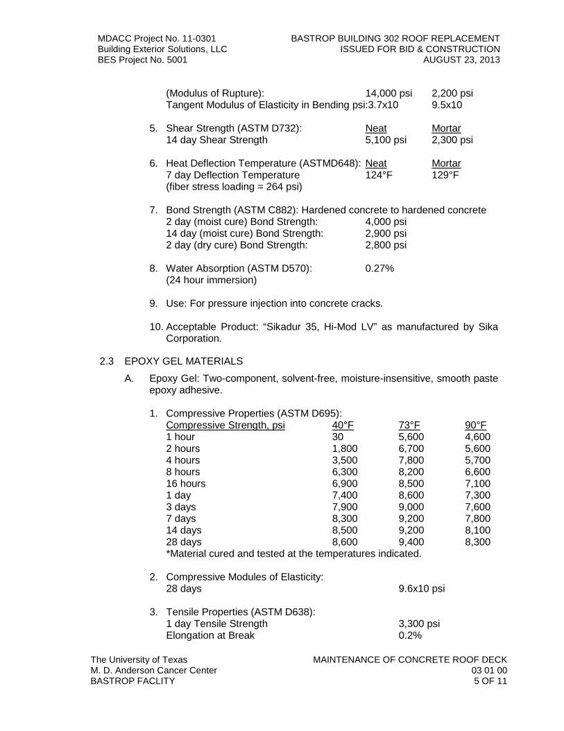
MDACC Project No. 11-0301 BASTROP BUILDING 302 ROOF REPLACEMENT Building Exterior Solutions, LLC ISSUED FOR BID & CONSTRUCTION BES Project No. 5001 AUGUST 23, 2013
The University of Texas MAINTENANCE OF CONCRETE ROOF DECK M. D. Anderson Cancer Center 03 01 00 BASTROP FACLITY 5 OF 11
(Modulus of Rupture): 14,000 psi 2,200 psi Tangent Modulus of Elasticity in Bending psi:3.7x10 9.5x10
5. Shear Strength (ASTM D732): Neat Mortar 14 day Shear Strength 5,100 psi 2,300 psi
6. Heat Deflection Temperature (ASTMD648): Neat Mortar 7 day Deflection Temperature 124°F 129°F (fiber stress loading = 264 psi)
7. Bond Strength (ASTM C882): Hardened concrete to hardened concrete 2 day (moist cure) Bond Strength: 4,000 psi 14 day (moist cure) Bond Strength: 2,900 psi 2 day (dry cure) Bond Strength: 2,800 psi
8. Water Absorption (ASTM D570): 0.27% (24 hour immersion)
9. Use: For pressure injection into concrete cracks.
10. Acceptable Product: “Sikadur 35, Hi-Mod LV” as manufactured by Sika
Corporation.
2.3 EPOXY GEL MATERIALS
A. Epoxy Gel: Two-component, solvent-free, moisture-insensitive, smooth paste epoxy adhesive. 1. Compressive Properties (ASTM D695):
Compressive Strength, psi 40°F 73°F 90°F 1 hour 30 5,600 4,600 2 hours 1,800 6,700 5,600 4 hours 3,500 7,800 5,700 8 hours 6,300 8,200 6,600 16 hours 6,900 8,500 7,100 1 day 7,400 8,600 7,300 3 days 7,900 9,000 7,600 7 days 8,300 9,200 7,800 14 days 8,500 9,200 8,100 28 days 8,600 9,400 8,300 *Material cured and tested at the temperatures indicated.
2. Compressive Modules of Elasticity: 28 days 9.6x10 psi
3. Tensile Properties (ASTM D638): 1 day Tensile Strength 3,300 psi Elongation at Break 0.2%

MDACC Project No. 11-0301 BASTROP BUILDING 302 ROOF REPLACEMENT Building Exterior Solutions, LLC ISSUED FOR BID & CONSTRUCTION BES Project No. 5001 AUGUST 23, 2013
The University of Texas MAINTENANCE OF CONCRETE ROOF DECK M. D. Anderson Cancer Center 03 01 00 BASTROP FACLITY 6 OF 11
Modulus of Elasticity 8.3x10 psi
4. Flexural Properties (ASTM D790): 1 day Flexural Strength (Modulus of Rupture): 4,800 psi Tangent Modulus of Elasticity in Bending psi: 1.2x10 psi
5. Shear Strength (ASTM D732): 1 day Shear Strength 2,200 psi
B. Use: For sealing cracks, securing injection ports prior to epoxy injection, and epoxy anchor grouting.
C. Acceptable Product: “Sikadur 33” as manufactured by Sika Corporation.
2.4 REINFORCEMENT PRIMER/CORROSION INHIBITOR
A. Bonding Agent and Reinforcement Protection: 3-component solvent-free, moisture-tolerant, epoxy modified, cementitious product specifically formulated as a bonding agent and an anticorrosion coating.
1. Properties:
Item Test Standard Time Value a. Compressive
Strength ASTM C-109 3 days 4500 psi 7 days 6500 psi 28 days 8500 psi
b. Flexural Strength ASTM C-348 28 days 1250 psi c. Splitting Tensile
Strength ASTM C-496 28 days 600 psi d. Bond Strength ASTM C-882 24 hours 2600 psi
2. Use: As an anti-corrosion coating for reinforcing steel and also as a
bonding agent for placing fresh concrete to existing concrete.
3. Acceptable Product: Sika Armatec 110 Epocem.
2.5 EPOXY MORTAR MATERIALS
A. Epoxy Mortar: Polymer-modified, Portland Cement based, two-component, non-sag, patching mortar specifically formulated for application by trowel on horizontal and vertical surfaces, and which forms an integral bond to existing concrete materials.
B. Properties:
Item Test Standard Property Value 1. Compressive
Strength ASTM C-109 1 day 3,000 psi 7 days 5,500 psi 28 days 7,000 psi

MDACC Project No. 11-0301 BASTROP BUILDING 302 ROOF REPLACEMENT Building Exterior Solutions, LLC ISSUED FOR BID & CONSTRUCTION BES Project No. 5001 AUGUST 23, 2013
The University of Texas MAINTENANCE OF CONCRETE ROOF DECK M. D. Anderson Cancer Center 03 01 00 BASTROP FACLITY 7 OF 11
2. Flexural Strength ASTM C-78 28 days 2,000 psi
3. Splitting Tensile
Strength ASTM C-496 28 days 7510 psi
4. Bond Strength ASTM C-882 28 days 3,200 psi
C. Thermal Coefficient of Expansion: Compatible with concrete (ASTM C884).
D. Use: For filling voids in existing cast-in-place concrete roof decks.
E. Color: Mix with appropriate pigments to match existing concrete.
F. Acceptable Product: “SikaTop 123” Plus as manufactured by Sika Corporation.
2.6 MIXING EPOXY MORTAR
A. Mix epoxy mortars to consistency recommended by the manufacturer for purpose intended.
B. Mix components in clean equipment or containers. Conform to pot life and workability limits.
C. Mix and apply materials in strict accordance with the manufacturer’s instructions and recommendations pertaining to proportions, methods, and mixtures, etc.
PART 3 - EXECUTION
3.1 EXAMINATION
A. Verify surfaces are ready to receive materials.
B. Beginning of installation means acceptance of existing surfaces.
C. Deteriorated concrete shall be investigated by “sounding” the concrete using hammer or chain-drag.
3.2 PREPARATION
A. Removal of Deteriorated or Damaged Concrete: 1. Concrete found to be cracked, spalled, or otherwise showing evidence of
disintegration or structural failure shall be cut out to sound surface. All unsound and disintegrated concrete must be removed.
2. Where required, edges of repair/patch areas shall be undercut to eliminate feather edges and to provide a keyed patch. Repair areas must have a minimum 1/8-inch depth.

MDACC Project No. 11-0301 BASTROP BUILDING 302 ROOF REPLACEMENT Building Exterior Solutions, LLC ISSUED FOR BID & CONSTRUCTION BES Project No. 5001 AUGUST 23, 2013
The University of Texas MAINTENANCE OF CONCRETE ROOF DECK M. D. Anderson Cancer Center 03 01 00 BASTROP FACLITY 8 OF 11
3. Where only partial-depth patching is required, additional precautions shall be taken to avoid breaking through or fracturing the concrete below the partial-depth patch area.
4. Special care shall be applied in removing unsound concrete from around reinforcing steel and embedded anchorages to prevent loss of bond in the remaining sound concrete.
5. Precautions shall be taken to prevent dust due to concrete removal from
entering the building and disrupting normal work functions.
B. Reinforcing Steel: 1. Loose concrete and rust on steel rods shall be removed by sandblasting,
chisel and hammer, or wire brush. Loose, scaly rust must be removed; thin, tightly-bonded rust need not be removed.
2. Contractor to notify Engineer if exposed reinforcement has lost over 20% of its cross-section due to corrosion.
3. Exposed reinforcing steel or dowels shall be restored to have a minimum of 1 ½-inch concrete clear cover replaced as indicated on the Drawings and within these Specifications. Remove sufficient amount of concrete around exposed steel using appropriate saw-cutting to facilitate proper surface preparation and patch repair as recommended by the repair mortar manufacturer.
4. Install reinforcement corrosion inhibitor in accordance with the
manufacturer’s recommendations.
C. Cleaning and Preparation of Repair Area: 1. After removal of unsound concrete, the area shall be flushed with high
pressure water or vacuum cleaned to remove loose particles and dust. Air blowing may be utilized, but the compressor shall be equipped with a functioning oil trap to prevent surface contamination.
2. Wash surface clean with water from hose prior to applying patching materials.
3.3 REPAIR WORK
A. Repair exposed structural, shrinkage, and settlement cracks of concrete by epoxy injection method.
B. Repair spalling. Prepare surface and fill voids flush with surface. Apply surface finish and allow to cure.

MDACC Project No. 11-0301 BASTROP BUILDING 302 ROOF REPLACEMENT Building Exterior Solutions, LLC ISSUED FOR BID & CONSTRUCTION BES Project No. 5001 AUGUST 23, 2013
The University of Texas MAINTENANCE OF CONCRETE ROOF DECK M. D. Anderson Cancer Center 03 01 00 BASTROP FACLITY 9 OF 11
3.4 EPOXY CRACK INJECTION
A. Area surrounding the crack shall be cleaned of efflorescence, deteriorated concrete, and other contaminants that may be detrimental to adhesion of the epoxy. If unsound or deteriorated concrete is located adjacent to the crack, and this could prevent complete injection of the crack, the unsound or deteriorated concrete shall be removed prior to the injection.
B. Apply a bank of epoxy gel approximately ¼-inch thick over cracks to be injected and around injection ports. Allow sufficient time to cure before pressure injecting.
C. Install injection ports at appropriate intervals to accomplish full penetration of the injection resin. Spacing of the injection ports shall be determined by size of the crack and depth of the concrete substrate. Generally, the spacing should be between four (4) and eight (8) inches.
D. Injection ports shall be installed using the following method: a. Surface Mounted Injection Ports:
1) Center injection port over the crack and secure in place using epoxy gel. Where possible install injection ports over the widest area along the length of the crack.
2) Completely seal exposed crack located between injection ports and other areas, as required, to prevent leaking of the resins, using epoxy gel.
3) If crack extends through the member and is accessible, install telltale injection ports on the opposite side and seal all exposed areas of the crack. Generally, spacing of the telltale injection ports should be between twelve (12) inches and twenty-four (24) inches.
b. No tape and seal method will be allowed.
E. Inject epoxy resin adhesive into prepared ports under pressure using equipment appropriate for particular application. Pressure shall be limited to a minimum of 35 psi at the point of entry into the crack, unless otherwise recommended by the manufacturer.
F. Begin injection at lower entry port and continue until adhesive appears in adjacent entry port. Continue from port to port until entire crack is filled.
G. Remove temporary seal and excess adhesive.
H. Clean surfaces adjacent to repair and blend finish.
3.5 APPLICATION - EPOXY MORTAR
A. Trowel apply mortar mix in lifts of 1/8 inches to one (1) inch in depth. Apply lifts in successive layers. Scratch previous layer and allow to set a minimum of thirty (30) minutes. Tamp into place filling voids at spalled areas.

MDACC Project No. 11-0301 BASTROP BUILDING 302 ROOF REPLACEMENT Building Exterior Solutions, LLC ISSUED FOR BID & CONSTRUCTION BES Project No. 5001 AUGUST 23, 2013
The University of Texas MAINTENANCE OF CONCRETE ROOF DECK M. D. Anderson Cancer Center 03 01 00 BASTROP FACLITY 10 OF 11
B. For patching honeycombs, trowel mortar onto surface, and work mortar into honeycomb to bring surface flush with surrounding area. Finish trowel surface to match surrounding area.
C. Cover exposed steel reinforcement with epoxy mortar; feather edges to flush surface.
D. At the time of application, the existing concrete surfaces shall be surface dry with no standing water.
E. Repair materials shall be scrubbed into the substrate, filling all pores and voids. Force repair materials against the edge of repair, working toward the center.
F. Upon filling the repair area, consolidate the repair material, then screed.
G. Allow repair materials to set to appropriate stiffness, then finish to match texture of adjacent existing concrete.
H. To increase the length of setting time during hot weather, utilize the following techniques: 1. Keep material in cool place prior to application. 2. Cool surface to which material is to be applied with clean, cold water. 3. Mix small batches and use quickly.
I. Do not permit patch to get hot in place. Sprinkle with cold water after placing. Fog-spray from hose or dash on water with brush.
J. Do not apply repair materials on frozen or frost-covered masonry or over frosted steel rods; frost must be removed by heating with blowtorch before application. During cool weather, keep material warm and use lukewarm mixing water to speed set.
K. In areas where the epoxy mortar will be applied over the corrosion inhibitor, mortar will be applied within the recommended allotted time as specified by the manufacturer.
3.6 FIELD QUALITY CONTROL
A. Inspection for complete coverage shall be made by Contractor to ensure all holes and voids have been filled, and all joints and cracks have been properly treated.
B. All improperly applied patching materials must be removed and surfaces shall be properly prepared and patched with new materials, then re-inspected.
3.7 CLEANING
A. Remove and properly discard all used material, packages, containers, and debris from the project site caused by application of the materials.
3.8 PROTECTION
A. Environmental:

MDACC Project No. 11-0301 BASTROP BUILDING 302 ROOF REPLACEMENT Building Exterior Solutions, LLC ISSUED FOR BID & CONSTRUCTION BES Project No. 5001 AUGUST 23, 2013
The University of Texas MAINTENANCE OF CONCRETE ROOF DECK M. D. Anderson Cancer Center 03 01 00 BASTROP FACLITY 11 OF 11
1. Precautions shall be taken to protect freshly placed patch or coating material from rain and runoff. Placement shall be stopped if rain starts and any damaged material shall be replaced. Protect from freezing.
2. Contractor shall be held responsible for protecting all adjacent construction from damage. Existing structures or installations which are destroyed or damaged by operations connected with this Work, including landscaping, shall be replaced or repaired by the Contractor to the satisfaction of the Owner at no additional expense.
B. Health: 1. Specified components can cause skin sensitization after pro-longed or
repeated contact. Utilize protection to limit exposure. 2. If product contacts eyes, hold eyelids apart and flush thoroughly for fifteen
(15) minutes. 3. Dust from the corrosion inhibitor may cause respiratory tract irritation.
Avoid breathing dust.
END OF SECTION 03 01 00
MDACC Project No. 11-0301 CLEANING OF EXISTING PRECAST CONCRETE Building Exterior Solutions, LLC ISSUED FOR BID & CONSTRUCTION BES Project No. 5001 AUGUST 23, 2013
The University of Texas CLEANING OF EXISTING PRECAST CONCRETE M. D. Anderson Cancer Center 03 01 40.51 BASTROP FACLITY 1 OF 4
SECTION 03 01 40.51
CLEANING OF PRECAST CONCRETE
PART 1 - GENERAL
1.1 SUMMARY
A. Section includes cleaning of precast concrete prior to application of elastomeric coating on the exterior walls of the building.
B. Related Sections:
1. Section 03 01 40.71 – Maintenance of Precast Concrete
2. Section 07 01 50 – Preparation for Re-Roofing
3. Section 07 56 00 – Fluid-Applied Elastomeric Wall Coating
1.2 SUBMITTALS
A. Section 01 33 00 – Submittal Procedures: Submittal procedures.
B. Materials: Submit a list of all materials and products proposed for use at this Project, giving product name, size, type, description, and name of manufacturer or supplier.
C. Product Data: Submit product standards, physical and chemical characteristics, technical specifications, limitations, installation instructions, maintenance instructions, and general recommendations regarding each material.
1.3 QUALITY ASSURANCE
A. Qualifications:
1. Manufacturer: Company specializing in manufacturing products specified in this section with minimum three (3) years documented experience.
2. Cleaner: Single installer specializing in performing Work of this section with minimum five (5) years documented experience in comparable masonry restoration projects and employing personnel skilled in the restoration processes and operations indicated.
B. Pre-Installation Conference:
1. Meet Owner’s Representative, Engineer, and related trades to discuss construction sequencing.

MDACC Project No. 11-0301 CLEANING OF EXISTING PRECAST CONCRETE Building Exterior Solutions, LLC ISSUED FOR BID & CONSTRUCTION BES Project No. 5001 AUGUST 23, 2013
The University of Texas CLEANING OF EXISTING PRECAST CONCRETE M. D. Anderson Cancer Center 03 01 40.51 BASTROP FACLITY 2 OF 4
1.4 DELIVERY, STORAGE, AND HANDLING
A. Deliver cleaning products neatly stacked and tied on pallets. Store clear of ground with adequate waterproof covering.
B. Store cleaning products in manufacturer’s packaging, or when delivered loose, with adequate waterproof covering.
C. Provide primary materials from the products of one manufacturer.
D. Provide secondary materials as required or recommended by primary materials manufacturer.
E. Deliver materials to jobsite with packages intact and with labels identifying manufacturer, product name and lot numbers when appropriate.
F. Store materials in a secure, dry, weathertight structure, in accordance with manufacturer’s recommendations
G. All materials shall be delivered to the jobsite, unloaded and stored as designated by the Owner’s Representative, in a manner which will facilitate subsequent renovation work and not unduly restrict Owner’s use of property. Contractor shall make all arrangements for loading and unloading his own materials.
1.5 ENVIRONMENTAL REQUIREMENTS
A. Hot and Cold Weather Requirements: American Concrete Institute (ACI) and cleaning product manufacturer’s recommendations.
1.6 PROJECT CONDITIONS
A. Contractor shall accept the conditions of the jobsite as they exist and perform his work accordingly.
B. Any adverse condition which might affect the performance of the Work described in these Specifications must be brought to the attention of the Engineer in writing immediately upon its discovery.
C. Contractor shall be held responsible for protecting all adjacent construction from damage. Existing structures or installations which are destroyed or damaged by operations connected with this Work, including landscaping, shall be replaced or repaired by the Contractor to the satisfaction of the Owner at no additional expense.
D. Contractor shall be held responsible for protecting the building interior against water leakage during renovation. Be prepared to immediately protect incomplete wall assemblies from water infiltration and damage due to inclement weather which may occur unexpectedly. Take all precautions necessary to temporarily cover each opened wall area and to seal perimeters and penetrations.

MDACC Project No. 11-0301 CLEANING OF EXISTING PRECAST CONCRETE Building Exterior Solutions, LLC ISSUED FOR BID & CONSTRUCTION BES Project No. 5001 AUGUST 23, 2013
The University of Texas CLEANING OF EXISTING PRECAST CONCRETE M. D. Anderson Cancer Center 03 01 40.51 BASTROP FACLITY 3 OF 4
E. Contractor shall secure field measurements as required for proper installation of Work covered by this Section. Exact measurements are the responsibility of the Contractor.
1.7 SEQUENCING
A. The Contractor shall coordinate each portion of this Work with other trades to ensure that all renovation work can be completed once it is begun, and to provide for appropriate inter-discipline interfacing.
PART 2 - PRODUCTS
2.1 PRECAST RESTORATION AND CLEANING
A. Manufacturers: 1. Prosoco, Inc.
2. Substitutions: Document 00 73 13 – Supplementary Conditions.
2.2 COMPONENTS
A. Cleaning Compound: “Enviro-Klean Biowash” by Prosoco, Inc.
B. Other materials, not specifically described but required for a complete and proper installation of the Work of this Section, shall be new, first quality of their respective kinds, and subject to review and acceptance by the Engineer.
PART 3 - EXECUTION
3.1 COORDINATION
A. Provide appropriate protection for adjacent finishes by providing drop clothes, etc., as required.
B. Coordinate the Work of this section with Owner’s Representative so as to provide minimum disturbance for the building users.
3.2 EXAMINATION
A. Verify surfaces to be renovated are ready for Work of this section.
B. Do not start Work until conditions are satisfactory.
3.3 PREPARATION
A. Immediately remove stains, efflorescence, or other excess resulting from Work of this section.
B. Protect new work, as well as ground level landscaping, from damage. Lay 1/2-inch plywood on roof surfaces over full extent of work area and traffic route.

MDACC Project No. 11-0301 CLEANING OF EXISTING PRECAST CONCRETE Building Exterior Solutions, LLC ISSUED FOR BID & CONSTRUCTION BES Project No. 5001 AUGUST 23, 2013
The University of Texas CLEANING OF EXISTING PRECAST CONCRETE M. D. Anderson Cancer Center 03 01 40.51 BASTROP FACLITY 4 OF 4
3.4 APPLICATION
A. All precast surfaces are to be cleaned with specified cleaner and then pressure washed with low pressure spray in accordance with recommendations by elastomeric coating manufacturer.
B. Protect people, vehicles, property and all surfaces not set for cleaning from product, splash, rinse, residue, fumes and wind drift.
C. Wash Down: 1. All concrete repair mortar shall be allowed to thoroughly cure before
cleaning. Adequate potable water supply shall be available to assure thorough presoaking and thorough rinsing of the surface. All surrounding non-masonry surfaces shall be tested and/or protected from exposure to the cleaning compound.
2. All traces of excess concrete repair mortar, efflorescence, existing corrosion stains and other construction stains shall be removed from exposed precast surfaces.
3. Use of cleaning compound shall be in strict accordance with manufacturer’s printed instructions.
3.5 SAFETY
A. Provide all necessary staging, scaffolding, ladders, and barricades necessary for the safe performance of this Work.
B. The working conditions at this site shall comply with OSHA safety requirements.
C. Barricades intended to route the public around work areas shall be of the plastic safety fence type.
3.6 CLEANING
A. As Work proceeds and on completion, remove excess mortar, sealant smears, and droppings.
B. Other surfaces on or below the wall being cleaned shall be protected and left clean and neat. All stains or dirt resulting from this operation, and affecting adjacent materials, shall be cleaned to the satisfaction of the Owner at no additional expense.
C. All trash, waste, and surplus materials, etc., shall be cleaned up, removed from site, and legally disposed of on a daily basis.
D. Pavement, grass, etc., at the storage and mixing areas shall be protected from damage.
END OF SECTION 03 01 40.51

MDACC Project No. 11-0301 BASTROP BUILDING 302 ROOF REPLACEMENT Building Exterior Solutions, LLC ISSUED FOR BID & CONSTRUCTION BES Project No. 5001 AUGUST 23, 2013
The University of Texas MAINTENANCE OF PRECAST CONCRETE M. D. Anderson Cancer Center 03 01 40.71 BASTROP FACLITY 1 OF 12
SECTION 03 01 40.71
MAINTENANCE OF PRECAST CONCRETE PART 1 - GENERAL
1.1 SUMMARY
A. Section includes the following:
1. Maintenance of precast concrete wall panels and decking prior to
application of elastomeric coating or installation of handrails on the exterior surfaces of the building.
2. Concrete slope at corral walkways and ramps at exterior elevator pads.
B. Related Sections:
1. Section 03 01 40.51 – Cleaning of Precast Concrete
2. Section 07 01 50 – Preparation for Re-Roofing
3. Section 07 52 13 – APP-Modified Bitumen Membrane Roofing
4. Section 07 56 00 – Fluid-Applied Elastomeric Wall Coating
5. Section 07 62 00 – Sheet Metal Flashing and Trim
6. Section 07 70 00 – Roof Specialties and Accessories
1.2 REFERENCES
A. ASTM International: 1. ASTM C78 – Test Method for Flexural Strength of Concrete (Using
Simple Beam with Third-Point Loading).
2. ASTM C109 – Standard Test Method for Compressive Strength of Hydraulic Cement Mortars (Using 2-inch Cube Specimens).
3. ASTM C150 – Standard Specification for Portland Cement.
4. ASTM C293 – Standard Test Method for Flexural Strength of Concrete (Using Simple Bean with Center-Point Loading).

MDACC Project No. 11-0301 BASTROP BUILDING 302 ROOF REPLACEMENT Building Exterior Solutions, LLC ISSUED FOR BID & CONSTRUCTION BES Project No. 5001 AUGUST 23, 2013
The University of Texas MAINTENANCE OF PRECAST CONCRETE M. D. Anderson Cancer Center 03 01 40.71 BASTROP FACLITY 2 OF 12
5. ASTM C496 – Test Method for Splitting Tensile Strength of Cylindrical Concrete Specimens.
6. ASTM C882 – Standard Test Method for Bond Strength of Epoxy-Resin Systems Used with Concrete by Slant Shear.
7. ASTM C884 – Test Method for Thermal Compatibility Between Concrete and an Epoxy-Resin Overlay.
B. “Guide for Surface Preparation for the Repair of Deteriorated Concrete Resulting From Reinforcing Steel Corrosion,” as published by the International Concrete Repair Institute (ICRI), Sterling, Virginia.
C. Where conflicts exist between this Specification and standards referred to, this Specification shall govern. Where manufacturer requirements are more stringent than this Specification, manufacturer requirements shall govern.
D. All Work shall conform to applicable federal, state, and local laws and regulations.
1.3 SUBMITTALS
A. Section 01 33 00 – Submittal Procedures: Submittal procedures.
B. Product Data: Submit product standards, physical and chemical characteristics, technical specifications, limitations, installation instructions, maintenance instructions, and general recommendations regarding each material.
C. Shop Drawings: If required by the Engineer, provide supplementary details as may be required for special conditions at this Project.
1.4 QUALITY ASSURANCE
A. Perform Work in accordance with local applicable standards.
B. Pre-Installation Conference:
1. Meet with Owner’s Representative, Engineer, and related trades to discuss concrete rehabilitation sequencing and installation procedures.
1.5 QUALIFICATIONS

MDACC Project No. 11-0301 BASTROP BUILDING 302 ROOF REPLACEMENT Building Exterior Solutions, LLC ISSUED FOR BID & CONSTRUCTION BES Project No. 5001 AUGUST 23, 2013
The University of Texas MAINTENANCE OF PRECAST CONCRETE M. D. Anderson Cancer Center 03 01 40.71 BASTROP FACLITY 3 OF 12
A. Manufacturer: Company specializing in manufacturing products specified in this section with minimum three (3) years documented experience.
B. Applicator: Company specializing in concrete repair with minimum three (3) years documented experience, and approved by manufacturer.
1.6 DELIVERY, STORAGE, AND HANDLING
A. Comply with instructions for storage, shelf life limitations, and handling.
B. Provide primary materials from the products of one manufacturer.
C. Provide secondary materials as required or recommended by primary
materials manufacturer.
D. Deliver materials to jobsite with packages intact and with labels identifying manufacturer, product name and lot numbers when appropriate.
E. Store materials in a cool, dry place off the ground in accordance with manufacturer’s recommendations, as well as the recommendations of the American Concrete Institute.
1.7 PROJECT CONDITIONS
A. Contractor shall accept the conditions of the jobsite as they exist and perform his work accordingly.
B. Any adverse conditions which might affect the performance of the Work described in this section must be brought to the attention of the Engineer in writing immediately upon its discovery.
C. Comply with manufacturer’s recommended minimum and maximum installation temperatures.
D. Any and all structural damage to existing construction components caused or brought about by the performance of this Work shall be replaced or repaired to the satisfaction of the Owner at no additional expense.
1.8 SEQUENCING AND SCHEDULING
A. Coordinate each portion of this Work with other trades to ensure that all construction can be completed once it is begun.
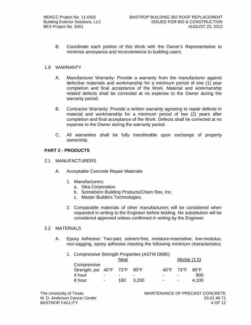
MDACC Project No. 11-0301 BASTROP BUILDING 302 ROOF REPLACEMENT Building Exterior Solutions, LLC ISSUED FOR BID & CONSTRUCTION BES Project No. 5001 AUGUST 23, 2013
The University of Texas MAINTENANCE OF PRECAST CONCRETE M. D. Anderson Cancer Center 03 01 40.71 BASTROP FACLITY 4 OF 12
B. Coordinate each portion of this Work with the Owner’s Representative to
minimize annoyance and inconvenience to building users.
1.9 WARRANTY
A. Manufacturer Warranty: Provide a warranty from the manufacturer against
defective materials and workmanship for a minimum period of one (1) year completion and final acceptance of the Work. Material and workmanship related defects shall be corrected at no expense to the Owner during the warranty period.
B. Contractor Warranty: Provide a written warranty agreeing to repair defects in material and workmanship for a minimum period of two (2) years after completion and final acceptance of the Work. Defects shall be corrected at no expense to the Owner during the warranty period.
C. All warranties shall be fully transferable upon exchange of property
ownership.
PART 2 - PRODUCTS
2.1 MANUFACTURERS
A. Acceptable Concrete Repair Materials 1. Manufacturers:
a. Sika Corporation. b. Sonneborn Building Products/Chem Rex, Inc. c. Master Builders Technologies.
2. Comparable materials of other manufacturers will be considered when
requested in writing to the Engineer before bidding. No substitution will be considered approved unless confirmed in writing by the Engineer.
2.2 MATERIALS
A. Epoxy Adhesive: Two-part, solvent-free, moisture-insensitive, low-modulus, non-sagging, epoxy adhesive meeting the following minimum characteristics: 1. Compressive Strength Properties (ASTM D695):
Neat Mortar (1:5) Compressive Strength, psi 40°F 73°F 90°F 40°F 73°F 90°F 4 hour - - - - - 800 8 hour - 180 3,200 - - 4,100

MDACC Project No. 11-0301 BASTROP BUILDING 302 ROOF REPLACEMENT Building Exterior Solutions, LLC ISSUED FOR BID & CONSTRUCTION BES Project No. 5001 AUGUST 23, 2013
The University of Texas MAINTENANCE OF PRECAST CONCRETE M. D. Anderson Cancer Center 03 01 40.71 BASTROP FACLITY 5 OF 12
16 hour 4,500 6,300 - 400 5,700 - 1 day - 6,000 9,100 120 5,000 6,900 3 days 4,000 10,700 10,500 6,200 6,800 7,000 7 days 6,800 11,000 10,500 6,300 7,900 8,800 14 days 10,300 12,000 10,500 6,800 8,500 8,800 28 days 12,400 13,000 10,500 7,000 8,600 8,800
2. Compressive
Modulus of Elasticity, psi Neat Mortar 7 days 3.2x10 28 days 8.1x10
3. Tensile Properties (ASTM D638): Neat Mortar
7 day Tensile Strength 8,900 psi 14 day Tensile Strength 840 psi Elongation at Break 5.4% 0.3% 14 day Modulus of Elasticity 4.1x10 psi 7.6x10 psi
4. Flexural Properties (ASTM D790): Neat Mortar
14 day Flexural Strength (Modulus of Rupture): 14,000 psi 2,200 psi Tangent Modulus of Elasticity in Bending psi:3.7x10 9.5x10
5. Shear Strength (ASTM D732): Neat Mortar 14 day Shear Strength 5,100 psi 2,300 psi
6. Heat Deflection Temperature (ASTMD648): Neat Mortar 7 day Deflection Temperature 124°F 129°F (fiber stress loading = 264 psi)
7. Bond Strength (ASTM C882): Hardened concrete to hardened concrete 2 day (moist cure) Bond Strength: 4,000 psi 14 day (moist cure) Bond Strength: 2,900 psi 2 day (dry cure) Bond Strength: 2,800 psi
8. Water Absorption (ASTM D570): 0.27% (24 hour immersion)
9. Use: For pressure injection into concrete cracks.
10. Acceptable Product: “Sikadur 35, Hi-Mod LV” as manufactured by Sika Corporation.
2.3 EPOXY GEL MATERIALS
A. Epoxy Gel: Two-component, solvent-free, moisture-insensitive, smooth paste
epoxy adhesive.

MDACC Project No. 11-0301 BASTROP BUILDING 302 ROOF REPLACEMENT Building Exterior Solutions, LLC ISSUED FOR BID & CONSTRUCTION BES Project No. 5001 AUGUST 23, 2013
The University of Texas MAINTENANCE OF PRECAST CONCRETE M. D. Anderson Cancer Center 03 01 40.71 BASTROP FACLITY 6 OF 12
1. Compressive Properties (ASTM D695):
Compressive Strength, psi 40°F 73°F 90°F 1 hour 30 5,600 4,600 2 hours 1,800 6,700 5,600 4 hours 3,500 7,800 5,700 8 hours 6,300 8,200 6,600 16 hours 6,900 8,500 7,100 1 day 7,400 8,600 7,300 3 days 7,900 9,000 7,600 7 days 8,300 9,200 7,800 14 days 8,500 9,200 8,100 28 days 8,600 9,400 8,300 *Material cured and tested at the temperatures indicated.
2. Compressive Modules of Elasticity: 28 days 9.6x10 psi
3. Tensile Properties (ASTM D638): 1 day Tensile Strength 3,300 psi Elongation at Break 0.2% Modulus of Elasticity 8.3x10 psi
4. Flexural Properties (ASTM D790): 1 day Flexural Strength (Modulus of Rupture): 4,800 psi Tangent Modulus of Elasticity in Bending psi: 1.2x10 psi
5. Shear Strength (ASTM D732): 1 day Shear Strength 2,200 psi
6. Use: For sealing cracks, securing injection ports prior to epoxy injection,
and epoxy anchor grouting.
7. Acceptable Product: “Sikadur 33” as manufactured by Sika Corporation. 2.4 REINFORCEMENT PRIMER/CORROSION INHIBITOR
A. Bonding Agent and Reinforcement Protection: 3-component solvent-free,
moisture-tolerant, epoxy modified, cementitious product specifically formulated as a bonding agent and an anticorrosion coating.
1. Properties:
Item Test Standard Time Value a. Compressive
Strength ASTM C-109 3 days 4500 psi 7 days 6500 psi 28 days 8500 psi

MDACC Project No. 11-0301 BASTROP BUILDING 302 ROOF REPLACEMENT Building Exterior Solutions, LLC ISSUED FOR BID & CONSTRUCTION BES Project No. 5001 AUGUST 23, 2013
The University of Texas MAINTENANCE OF PRECAST CONCRETE M. D. Anderson Cancer Center 03 01 40.71 BASTROP FACLITY 7 OF 12
b. Flexural Strength ASTM C-348 28 days 1250 psi c. Splitting Tensile
Strength ASTM C-496 28 days 600 psi d. Bond Strength ASTM C-882 24 hours 2600 psi
2. Use: As an anti-corrosion coating for reinforcing steel and also as a
bonding agent for placing fresh concrete to existing concrete.
3. Acceptable Product: Sika Armatec 110 Epocem.
2.5 EPOXY MORTAR MATERIALS
A. Epoxy Mortar: Polymer-modified, Portland Cement based, two-component, non-sag, patching mortar specifically formulated for application by trowel on horizontal and vertical surfaces, and which forms an integral bond to existing concrete materials.
1. Properties:
Item Test Standard Property Value a. Compressive Strength: ASTM C109 1 day 3,500 psi
7 days 6,000 psi 28 days 7,000 psi
b. Flexural strength: ASTM C78 28 days 2,000 psi c. Splitting Tensile Strength: ASTM C496 28 days 900 psi d. Bond Strength: ASTM C882 28 days 2,200 psi
2. Thermal Coefficient of Expansion: Compatible with concrete (ASTM
C884).
3. Use: For filling voids in existing precast concrete panels.
4. Color: Mix with appropriate pigments to match existing concrete.
5. Acceptable Product: “SikaTop 123 Plus” as manufactured by Sika Corporation.
2.6 MIXING EPOXY MORTAR
A. Mix epoxy mortars to consistency recommended by the manufacturer for
purpose intended.
B. Mix components in clean equipment or containers. Conform to pot life and workability limits.
C. Mix and apply materials in strict accordance with the manufacturer’s instructions and recommendations pertaining to proportions, methods, and mixtures, etc.

MDACC Project No. 11-0301 BASTROP BUILDING 302 ROOF REPLACEMENT Building Exterior Solutions, LLC ISSUED FOR BID & CONSTRUCTION BES Project No. 5001 AUGUST 23, 2013
The University of Texas MAINTENANCE OF PRECAST CONCRETE M. D. Anderson Cancer Center 03 01 40.71 BASTROP FACLITY 8 OF 12
PART 3 - EXECUTION
3.1 EXAMINATION
A. Verify surfaces are ready to receive materials.
B. Beginning of installation means acceptance of existing surfaces.
C. Deteriorated concrete shall be investigated by "sounding" the concrete using hammer.
3.2 PREPARATION
A. Removal of Deteriorated or Damaged Concrete: 1. Concrete found to be cracked, spalled, or otherwise showing evidence of
disintegration or structural failure shall be cut out to sound surface. All unsound and disintegrated concrete must be removed.
2. Where required, edges of repair/patch areas shall be undercut to eliminate feather edges and to provide a keyed patch. Repair areas must have a minimum 1/8-inch depth.
3. Where only partial-depth patching is required, additional precautions shall be taken to avoid breaking through or fracturing the concrete below the partial-depth patch area.
4. Special care shall be applied in removing unsound concrete from around reinforcing steel and embedded anchorages to prevent loss of bond in the remaining sound concrete.
5. Adequate precautions shall be taken to mitigate hazards from falling debris as demolition proceeds.
6. Precautions shall be taken to prevent dust due to concrete removal from entering the building and disrupting normal work functions.
B. Reinforcing Steel:
1. Loose concrete and rust on steel rods shall be removed by sandblasting,
chisel and hammer, or wire brush. Loose, scaly rust must be removed; thin, tightly-bonded rust need not be removed.
2. Contractor to notify Engineer if exposed reinforcement has lost over 20% of its cross-section due to corrosion.

MDACC Project No. 11-0301 BASTROP BUILDING 302 ROOF REPLACEMENT Building Exterior Solutions, LLC ISSUED FOR BID & CONSTRUCTION BES Project No. 5001 AUGUST 23, 2013
The University of Texas MAINTENANCE OF PRECAST CONCRETE M. D. Anderson Cancer Center 03 01 40.71 BASTROP FACLITY 9 OF 12
3. Exposed reinforcing steel or dowels shall be restored to have a minimum of 1 ½-inch concrete clear cover replaced as indicated on the Drawings and within these Specifications. Remove sufficient amount of concrete around exposed steel using appropriate saw-cutting to facilitate proper surface preparation and patch repair as recommended by the repair mortar manufacturer..
4. Install reinforcement corrosion inhibitory in accordance with the
manufacturer’s recommendations.
C. Cleaning and Preparation of Repair Area: 1. After removal of unsound concrete, the area shall be flushed with high
pressure water or vacuum cleaned to remove loose particles and dust. Air blowing may be utilized, but the compressor shall be equipped with a functioning oil trap to prevent surface contamination.
2. Wash surface clean with water from hose prior to applying patching materials.
3.3 REPAIR/RESTORATION
A. Repair Work: 1. Repair exposed structural, shrinkage, and settlement cracks of concrete
by epoxy injection method.
2. Repair spalling. Prepare surface and fill voids flush with surface. Apply surface finish and allow to cure.
B. Epoxy Crack Injection: 1. Area surrounding the crack shall be cleaned of efflorescence,
deteriorated concrete, and other contaminants that may be detrimental to adhesion of the epoxy. If unsound or deteriorated concrete is located adjacent to the crack, and this could prevent complete injection of the crack, the unsound or deteriorated concrete shall be removed prior to the injection.
2. Apply a bank of epoxy gel approximately ¼-inch thick over cracks to be injected and around injection ports. Allow sufficient time to cure before pressure injecting.
3. Install injection ports at appropriate intervals to accomplish full penetration of the injection resin. Spacing of the injection ports shall be determined by size of the crack and depth of the concrete substrate. Generally, the spacing should be between four (4) and eight (8) inches.

MDACC Project No. 11-0301 BASTROP BUILDING 302 ROOF REPLACEMENT Building Exterior Solutions, LLC ISSUED FOR BID & CONSTRUCTION BES Project No. 5001 AUGUST 23, 2013
The University of Texas MAINTENANCE OF PRECAST CONCRETE M. D. Anderson Cancer Center 03 01 40.71 BASTROP FACLITY 10 OF 12
4. Injection ports shall be installed using the following method:
a. Surface Mounted Injection Ports: 1) Center injection port over the crack and secure in place using
epoxy gel. Where possible install injection ports over the widest area along the length of the crack.
2) Completely seal exposed crack located between injection ports and other areas, as required, to prevent leaking of the resins, using epoxy gel.
3) If crack extends through the member and is accessible, install telltale injection ports on the opposite side and seal all exposed areas of the crack. Generally, spacing of the telltale injection ports should be between twelve (12) inches and twenty-four (24) inches.
b. No tape and seal method will be allowed.
5. Inject epoxy resin adhesive into prepared ports under pressure using equipment appropriate for particular application. Pressure shall be limited to a minimum of 35 psi at the point of entry into the crack, unless otherwise recommended by the manufacturer.
6. Begin injection at lower entry port and continue until adhesive appears in adjacent entry port. Continue from port to port until entire crack is filled.
7. Remove temporary seal and excess adhesive.
8. Clean surfaces adjacent to repair and blend finish. C. Epoxy Mortar:
1. Trowel apply mortar mix in lifts of 1/8 inches to one (1) inch in depth.
Apply lifts in successive layers. Scratch previous layer and allow to set a minimum of 30 minutes. Tamp into place filling voids at spalled areas.
2. For patching honeycombs, trowel mortar onto surface, and work mortar into honeycomb to bring surface flush with surrounding area. Finish trowel surface to match surrounding area.
3. Cover exposed steel reinforcement with epoxy mortar; feather edges to flush surface.
4. At the time of application, the existing concrete surfaces shall be surface dry with no standing water.
5. Repair materials must be scrubbed into the substrate, filling all pores and voids. Force repair materials against the edge of repair, working toward the center.

MDACC Project No. 11-0301 BASTROP BUILDING 302 ROOF REPLACEMENT Building Exterior Solutions, LLC ISSUED FOR BID & CONSTRUCTION BES Project No. 5001 AUGUST 23, 2013
The University of Texas MAINTENANCE OF PRECAST CONCRETE M. D. Anderson Cancer Center 03 01 40.71 BASTROP FACLITY 11 OF 12
6. Upon filling the repair area, consolidate the repair material, then screed.
7. Allow repair materials to set to appropriate stiffness, then finish to match texture of adjacent existing concrete.
8. To increase the length of setting time during hot weather, utilize the following techniques: a. Keep material in cool place prior to application. b. Cool surface to which material is to be applied with clean, cold water. c. Mix small batches and use quickly.
9. Do not permit patch to get hot in place. Sprinkle with cold water after
placing. Fog-spray from hose or dash on water with brush.
10. Do not apply repair materials on frozen or frost-covered masonry or over frosted steel rods; frost must be removed by heating with blowtorch before application. During cool weather, keep material warm and use lukewarm mixing water to speed set.
11. In areas where the epoxy mortar will be applied over the corrosion inhibitor, mortar will be applied within the recommended allotted time as specified by the manufacturer.
3.4 FIELD QUALITY CONTROL
A. Inspection for complete coverage shall be made by Contractor to ensure all holes and voids have been filled, and all joints and cracks (greater than 0.2mm) have been properly treated.
B. All previously applied patching materials must be removed and surfaces shall be properly prepared and patched with new materials, then re-inspected.
3.5 CLEANING
A. Remove and properly discard all used material, packages, containers, and debris from the project site caused by application of the materials.
3.6 PROTECTION
A. Environmental: 1. Precautions shall be taken to protect freshly placed patch or coating
material from rain and runoff. Placement shall be stopped if rain starts and any damaged material shall be replaced. Protect from freezing.

MDACC Project No. 11-0301 BASTROP BUILDING 302 ROOF REPLACEMENT Building Exterior Solutions, LLC ISSUED FOR BID & CONSTRUCTION BES Project No. 5001 AUGUST 23, 2013
The University of Texas MAINTENANCE OF PRECAST CONCRETE M. D. Anderson Cancer Center 03 01 40.71 BASTROP FACLITY 12 OF 12
2. Contractor shall be held responsible for protecting all adjacent construction from damage. Existing structures or installations which are destroyed or damaged by operations connected with this Work, including landscaping, shall be replaced or repaired by the Contractor to the satisfaction of the Owner at no additional expense.
B. Health: 1. Specified components can cause skin sensitization after pro-longed or
repeated contact. Utilize protection to limit exposure.
2. If product contacts eyes, hold eyelids apart and flush thoroughly for fifteen (15) minutes.
3. Dust from the corrosion inhibitor may cause respiratory tract irritation. Avoid breathing dust.
PART 4 - SCHEDULE
4.1 Base bid: The following work shall be included in the pricing for maintenance on the precast:
A. Remove all unsound concrete at spall locations. Square edges around all spall areas to prevent feather-edging of repair mortar in order to restore initial dimension of precast.
END OF SECTION 03 01 40.71

MDACC Project No. 11-0301 BASTROP BUILDING 302 ROOF REPLACEMENT Building Exterior Solutions, LLC ISSUED FOR BID & CONSTRUCTION BES Project No. 5001 AUGUST 23, 2013
The University of Texas METAL FABRICATIONS M. D. Anderson Cancer Center 05 50 00 BASTROP FACILITY 1 OF 6
SECTION 05 50 00
METAL FABRICATIONS
PART 1 - GENERAL
1.1 SUMMARY
A. This Section includes the following:
1. Miscellaneous steel framing and supports for mechanical and electrical equipment, where indicated.
B. Related sections include the following:
1. Section 07 01 50 – Preparation for Re-roofing
2. Section 07 52 13 – APP-Modified Bituminous Membrane Roofing
3. Section 07 62 00 – Sheet Metal Flashing and Trim
4. Section 23 31 00 – Basic Mechanical Materials and Methods
1.2 REFERENCES
1. American Institute of Steel Construction (AISC) – “Manual of Steel Construction”, latest edition.
2. American Steel and Iron Institute (AISI) – “Specifications for the Design of Cold-formed Steel Structural Members”, latest edition.
3. American Welding Society (AWS) – “Structural Welding Code”, latest edition.
4. American Society of Civil Engineers (ASCE), “Minimum Design Loads for Buildings and Other Structures”, latest edition.
1.3 ACTION SUBMITTALS
A. Product Data: For each type of process and factory-fabricated product indicated.
1. Submittals shall be provided in three sets, unless noted otherwise.
B. Shop Drawings: Show fabrication and installation details for metal fabrications and their connections. Show anchorage, components, and accessory items.
C. Design Calculations: Submit design calculations, indicating compliance with specified performance criteria. Indicate fastener types and spacing. Design calculations and shop drawings shall bear shall bear the seal of a professional Engineer licensed in the State of Texas.

MDACC Project No. 11-0301 BASTROP BUILDING 302 ROOF REPLACEMENT Building Exterior Solutions, LLC ISSUED FOR BID & CONSTRUCTION BES Project No. 5001 AUGUST 23, 2013
The University of Texas METAL FABRICATIONS M. D. Anderson Cancer Center 05 50 00 BASTROP FACILITY 2 OF 6
1.4 QUALITY ASSURANCE
A. Installer Qualifications: Must have installations of specified materials in local area in use for a minimum of five years.
1. Employ a foreman with a minimum of five years experience as foreman on similar projects, who is fluent in English, to be on-site at all times during work.
B. Mock-ups: Build mockups to demonstrate aesthetic effects and set quality standards for fabrication and installation.
1. Build mock-up of typical steel units.
2. Approved mock-ups may become part of the completed Work if undisturbed at Substantial Completion.
C. Pre-installation meeting:
1. Conduct meeting at Project site.
2. Review requirements for metal fabrication work, including: a. Construction schedule and availability of materials, Installer’s
personnel, equipment, and facilities needed to make progress and avoid delays.
b. Surface preparation and substrate condition and pretreatment. c. Installation procedures. d. Special details.
1.5 SYSTEM DESCRIPTION
A. Design Requirements:
1. New supports shall be designed and fabricated in accordance with the applicable AISC, AISI, AWS, MBMA, and ANSI specifications, using materials listed below. Where conflicts exist between this specification and the standards referenced herein, this specification shall govern, unless local codes are more stringent, in which case local codes shall govern.
2. All new construction shall be interfaced with and integrated into existing constructions In a manner as to provide a structurally-sound, weathertight, and durable structure. Installations pertaining to new building components shall match and/or endeavor to complement the existing building components as much as possible.
3. All work of this Section shall conform to all applicable Federal, State and local laws and regulations.
B. Installation Requirements:
1. Any and all damage to existing building components caused the performance of this work shall be replaced or repaired to the satisfaction of the Owner at no additional expense.

MDACC Project No. 11-0301 BASTROP BUILDING 302 ROOF REPLACEMENT Building Exterior Solutions, LLC ISSUED FOR BID & CONSTRUCTION BES Project No. 5001 AUGUST 23, 2013
The University of Texas METAL FABRICATIONS M. D. Anderson Cancer Center 05 50 00 BASTROP FACILITY 3 OF 6
2. Maximum allowable deflection is L/240.
PART 2 - PRODUCTS
2.1 METALS, GENERAL
A. Metal Surfaces, General: Provide materials with smooth, flat surfaces without blemishes.
2.2 FERROUS METALS
A. Steel Plates, Shapes, and Bars: ASTM A36/A36M.
B. Steel Tubing: ASTM A500, cold-formed steel tubing
C. Steel Pipe: ASTM A53/A53M
D. Slotted Channel Framing: Cold-formed metal box channels (struts) complying with MFMA-4.
E. Material: Galvanized Steel, ASTM A653/A653M, structural steel, Grade 33, with G90 coating; 0.079-inch nominal thickness or 0.45 ounces per square feet of surface area.
2.3 FASTENERS
A. Anchor Bolts: ASTM F1554, Grade 36, of dimensions indicated, with nuts, ASTM A563; and, where indicated, flat washers.
1. Hot-dip galvanized or provide mechanically deposited, zinc coating where item being fastened is indicated to be galvanized.
2.4 MISCELLANEOUS MATERIALS
A. Galvanizing Repair Compound: High-zinc dust-content paint complying with SSPC-Paint 20 and compatible with paints specified to be used over it.
B. Bituminous Paint: Cold-applied asphalt emulsion complying with ASTM D1187.
C. Non-shrink, Non-metallic Grout: Factory-packaged, non-staining, non-corrosive, non-gaseous grout complying with ASTM C1107. Provide grout specifically recommended by the manufacturer for interior and exterior applications.
2.5 FABRICATION, GENERAL
A. Shop Assembly: Preassemble items in the shop to the greatest extent possible. Use connections that maintain structural value of joined pieces.
B. Cut, drill, and punch metals cleanly and accurately. Remove burrs and ease edges. Remove sharp or rough areas on exposed surfaces.
C. Weld corners and seams continuously to comply with the following:

MDACC Project No. 11-0301 BASTROP BUILDING 302 ROOF REPLACEMENT Building Exterior Solutions, LLC ISSUED FOR BID & CONSTRUCTION BES Project No. 5001 AUGUST 23, 2013
The University of Texas METAL FABRICATIONS M. D. Anderson Cancer Center 05 50 00 BASTROP FACILITY 4 OF 6
1. Use materials and methods that minimize distortion and develop strength and corrosion resistance of base metals.
2. Obtain fusion without undercut or overlap.
3. Remove welding flux immediately.
4. At exposed connections, finish exposed welds and surfaces smooth and blended.
D. Form exposed connections with hairline joints, flush and smooth, using concealed fasteners or welds where possible. Locate joints where least conspicuous.
E. Fabricate seams and other connections that will be exposed to weather in a manner to exclude water. Provide weep holes where water may accumulate.
2.6 MISCELLANEOUS FRAMING AND SUPPORTS
A. General: Provide steel framing and supports not specified in other Sections as needed to complete the Work.
B. Fabricate the units from steel shapes, plates, and bars of welded construction unless otherwise indicated. Fabricate to sizes, shapes, and profiles indicated and as necessary to receive adjacent construction.
C. Fabricate steel columns from steel pipe with steel baseplates and top plates as indicated. Drill or punch baseplates and top plates for anchor and connection blots and weld pipe to pipe with fillet welds all around. Make welds the same size as pipe wall thickness unless otherwise indicated.
1. Unless otherwise indicated, fabricate from Schedule 40 steel pipe.
2. Unless otherwise indicated, provide ½” (12.7-mm) baseplates with four 5/8” (16-mm) anchor bolts and 3/8” (6.4-mm) top plates.
D. Galvanize miscellaneous framing and supports where indicated.
2.7 STEEL AND IRON FINISHES
A. Galvanizing: Hot-dip galvanize items as indicated to comply with ASTM A153/A153M for steel and iron hardware and with ASTM A123/A123M for other steel and iron products.
PART 3 - EXECUTION
3.1 INSTALLATION, GENERAL
A. Cutting, Fitting, and Placement: Perform cutting, drilling, and fitting required for installing metal fabrications. Set metal fabrications accurately in location, alignment, and elevation; with edges and surfaces level, plumb, true and free of rack; and measured from established lines and levels.

MDACC Project No. 11-0301 BASTROP BUILDING 302 ROOF REPLACEMENT Building Exterior Solutions, LLC ISSUED FOR BID & CONSTRUCTION BES Project No. 5001 AUGUST 23, 2013
The University of Texas METAL FABRICATIONS M. D. Anderson Cancer Center 05 50 00 BASTROP FACILITY 5 OF 6
B. Fit exposed connections accurately together to form hairline joints. Weld connections that are not to be left as exposed joints but cannot be shop-welded due to shipping sixe limitations. Do not weld, cut, or adrade surfaces of exterior units that have been hot-dipped galvanized after fabrication and are bolted or screwed field connections.
C. Field Welding: Comply with the following requirements:
1. Use materials and methods that minimize distortion and develop strength and corrosion resistance of base metals.
2. Obtain fusion without undercut or overlap.
3. Remove welding flux immediately.
4. At exposed connections, finish expose welds and surfaces smooth and blended.
D. Fastening to In-Place Construction: Provide anchorage devices and fasteners where metal fabrications are required to be fastened to in-place construction.
E. Provide temporary bracing or anchors in formwork for items that are to be built into concrete, masonry, or similar construction.
3.2 INSTALLING MISCELLANEOUS FRAMING AND SUPPORTS
A. General: Install framing and supports to comply with requirements of the items being supported, including manufacturer’s written instructions and requirements indicated on shop drawings.
3.3 FINISHING AND PAINTING
A. If retained steel framing exhibits moderate corrosion, perform necessary surface preparation using a rotary wire brush to remove surface rust, clean, and paint local areas using a cold-galvanizing field-applied product (i.e., “Os-pho” by Staybryte or approved equal.
B. All field welds are to be inspected by a certified weld inspector having current credentials that are approved by Engineer prior to inspection.
C. Corrective Work:
1. Members or assemblies of work of this section having fabrication errors, or which exceed permissible tolerances, or which have errors or deformations preventing proper assembly and fitting of parts, shall be reported immediately to Owner’s representative or be replaced immediately.
2. Such members of assemblies shall be corrected if permitted by Engineer.
3.4 ADJUSTING AND CLEANING
A. Touch-up Painting: Immediately after erection, clean field welds, bolted connections, and abraded areas. Paint uncoated and abraded areas with the

MDACC Project No. 11-0301 BASTROP BUILDING 302 ROOF REPLACEMENT Building Exterior Solutions, LLC ISSUED FOR BID & CONSTRUCTION BES Project No. 5001 AUGUST 23, 2013
The University of Texas METAL FABRICATIONS M. D. Anderson Cancer Center 05 50 00 BASTROP FACILITY 6 OF 6
same material used for shop painting to comply with SSPC-PA 1 for touching-up shop painted surfaces.
B. Remove from the job site and legally dispose of all trash and debris from the project site. Remove all surplus materials, tools, and equipment from the project site.
C. Carefully inspect all completed work and correct all defects.
END OF SECTION 05 50 00
MDACC Project No. 11-0301 BASTROP BUILDING 302 ROOF REPLACEMENT Building Exterior Solutions, LLC ISSSUED FOR BID & CONSTRUCTION BES Project No. 5001 AUGUST 23, 2013
The University of Texas ROUGH CARPENTRY M. D. Anderson Cancer Center 06 10 00 BASTROP FACILITY 1 OF 5
SECTION 06 10 00
ROUGH CARPENTRY
PART 1 - GENERAL
1.1 SUMMARY
A. This Section includes the following:
1. Miscellaneous wood blocking, cants, nailers, and fasteners at all perimeters and at new wood curbs and curb modifications.
B. Related sections include the following: 1. Section 07 01 50 – Preparation for Re-roofing
2. Section 07 52 13 – APP-Modified Bituminous Membrane Roofing
3. Section 07 62 00 – Sheet Metal Flashing and Trim
1.2 DEFINTIONS
A. Rough Carpentry: Carpentry work not specified in other Sections and not exposed, unless otherwise indicated.
B. Lumber grading agencies, and the abbreviations used to reference them, including the following:
1. NELMA – Northeastern Lumber Manufacturers Association.
2. NLGA – National Lumber Grades Authority.
3. SPIB – Southern Pine Inspection Bureau.
4. WCLIB – West Coast Lumber Inspection Bureau.
5. WWPA – Western Wood Products Association.
1.3 REFERENCES
1. National Forest Products Association, Standard 255, latest edition.
2. American Soft Lumber Standard, PS-20, latest edition.
3. Factory Mutual, Loss Prevention Data Sheet 1-49, “Perimeter Flashing”.
4. AWPA C-2, C-9, LP-2, M-4, U-1, and T-1.
1.4 SUBMITTALS
A. Product Data: For each type of process and factory-fabricated product indicated.

MDACC Project No. 11-0301 BASTROP BUILDING 302 ROOF REPLACEMENT Building Exterior Solutions, LLC ISSSUED FOR BID & CONSTRUCTION BES Project No. 5001 AUGUST 23, 2013
The University of Texas ROUGH CARPENTRY M. D. Anderson Cancer Center 06 10 00 BASTROP FACILITY 2 OF 5
1. Submittals shall be provided in three sets, unless noted otherwise.
2. Include data for wood-preservative treatment from chemical treatment manufacturer and certification by treating plant that materials comply with requirements.
B. Evaluation Reports: For the following:
1. Treated wood. a. Delivery, storage, and handling b. Stack lumber, plywood, and other panels.
C. Fastener type, size, and frequency for all edge nailers.
PART 2 - PRODUCTS
2.1 WOOD PRODUCTS, GENERAL
A. Lumber: DOC PS 20 and applicable rules of lumber grading agencies certified
by the American Lumber Standards Committee Board of Review.
1. Factory mark each piece of lumber with grade stamp of grading agency.
2. Where nominal sizes are indicated, provide actual sizes required by DOC PS 20 for moisture content specified. Where actual sizes are indicated, they are the minimum dressed size for dry lumber.
3. Provide dressed lumber, S4S, unless otherwise indicated.
4. Provide dry lumber with 19 percent maximum moisture content or less, as measured by a Delmhurst moisture meter calibrated for wood, or equivalent, at the time of dressing for two-inch nominal thickness or less, unless otherwise indicated.
2.2 WOOD-PRESERVATIVE-TREATED MATERIALS
A. Preservative Treatment by Pressure Process: AWPA Standard U1 and AWPA Standard T1. Lumber that is not in contact with the ground and is continuously protected from liquid water may be treated for Use Category UC2. All other wood indicated in this Section or the Drawings to be Use Category UC4A. 1. Preservative Chemicals: Water-borne preservatives or Oxine Copper
(copper-8-quinolinolate) acceptable to authorities having jurisdiction.
B. Kiln-dry material after treatment to maximum moisture content of 19 percent for lumber and 15 percent for plywood. Do not use material that is warped or does not comply with requirements for untreated material.
C. Mark each treated item with treatment quality mark of an inspection agency approved by the American Lumber Standards Committee Board of Review.

MDACC Project No. 11-0301 BASTROP BUILDING 302 ROOF REPLACEMENT Building Exterior Solutions, LLC ISSSUED FOR BID & CONSTRUCTION BES Project No. 5001 AUGUST 23, 2013
The University of Texas ROUGH CARPENTRY M. D. Anderson Cancer Center 06 10 00 BASTROP FACILITY 3 OF 5
D. Application: Treat items indicated on Drawings, and the following: 1. Wood cants, nailers, curbs, equipment support bases, blocking, stripping,
and similar members in connection with roofing, flashing, vapor barriers, and waterproofing.
2. Field-Applied Preservative Treatment: AWPA M4-02, minimum 2% solids, Copper Napthenate solution.
2.3 MISCELLANEOUS LUMBER AND PLYWOOD
A. General: Provide lumber for support or attachment of other construction, including the following:
1. Rooftop equipment bases and support curbs
2. Blocking: Provide minimum of six inch nominal width.
3. Cants: Provided minimum of four inch face.
4. Nailers: Provide minimum of six inch nominal width.
5. Plywood: Provided minimum of 3/4 inch thickness on horizontal plane and 5/8 inch thickness on vertical plane.
B. For concealed boards and dimension lumber size, provide No. 2 or better grade lumber free of cracks, warping, splitting and excessive knots,with 19 percent maximum moisture content of any species and grades:
1. Mixed southern pine, No. 2 grade; SPIB.
2. Spruce-pine-fur: NELMA, NLGA, WCLIB, or WWPA.
C. Plywood: Provide marine-grade plywood of thickness indicated.
2.4 MISCELLANEOUS MATERIALS
A. Fasteners:
1. General: Where rough carpentry is exposed to weather, in ground contact, or in area of high relative humidity, provide Type 304 stainless steel fasteners. a. Where stainless steel fasteners cannot be obtained, fasteners with
a hot-dip zinc coating complying with ASTM A153 may be used.
2. Wood nailers to concrete: X-CR-L 72 P8 S23 stainless steel powder-actuated fastener by Hilti North America.
3. Wood nailer to wood nailer: #10 X 3” stainless steel wood screws.
4. Miscellaneous Common Nails: Provide Type 304 stainless steel common nails. a. 16d Common Nail: 0.162” diameter x 3 ½” length b. 10d Common Nail: 0.148” diameter x 3” length c. 8d Common Nail: 0.131” diameter x 2 1/2” length

MDACC Project No. 11-0301 BASTROP BUILDING 302 ROOF REPLACEMENT Building Exterior Solutions, LLC ISSSUED FOR BID & CONSTRUCTION BES Project No. 5001 AUGUST 23, 2013
The University of Texas ROUGH CARPENTRY M. D. Anderson Cancer Center 06 10 00 BASTROP FACILITY 4 OF 5
5. Bolts: Steel bolts complying with ASTM A 307, Grade A; with ASTM A563 hex nuts and, where indicated, flat washers.
PART 3 - EXECUTION
3.1 INSTALLATION, GENERAL
A. Set rough carpentry to required levels and lines, with members plumb, true to line, cut, and fitted. Fit rough carpentry to other construction; scribe and cope as needed for accurate fit. Locate nailers, blocking, and similar supports to comply with requirements for attaching other construction.
B. Do not use materials with defects that impair quality of rough carpentry or pieces that are of inadequate size or length to use in optimal joint arrangement or as needed to minimize the number of required pieces.
C. Apply field treatment complying with AWPA M4 to cut surfaces of preservative-treated lumber and plywood. Apply a minimum of two coats per manufacturer’s recommendations.
D. Securely attach rough carpentry work to substrate by anchoring and fastening as indicated, complying with the following:
1. Published requirements of metal framing anchor manufacturer.
2. Table 23-II-B-1, “Nailing Schedule,” and Table 23-II-B-2, “Wood Structural Panel Roof Sheathing Nailing Schedule,” in the Uniform Building Code.
3. Table 2305.2, “Fastening Schedule,” in the BOCA National Building Code.
4. Table 2306.1, “Fastening Schedule,” in the Standard Building Code.
5. Table 602.3(1), “Fastener Schedule for Structural Members,” and Table 602.3(2), “Alternate Attachments,” in the International One- and Two-Family Dwelling Code.
6. CABO NER – 272 for power-driven fasteners.
E. Select fasteners of size that will not fully penetrate members where opposite side will be exposed to view or will received finish materials. Make tight connections between members. Install fasteners without splitting wood.
F. For hardware, anchors, and connectors, use fasteners in all holes per manufacturer’s recommendations, unless indicated otherwise.
G. Lag bolts and screws: Pre-drill for lag bolts and lag screws to diameter a base of threads and length equal to embedment.
H. Bolting: Drill holes 1/16” larger in diameter than the bolts used. Drill straight and true from one side only. Use washers under head and nut where both bear on wood. Use washers under all nuts.

MDACC Project No. 11-0301 BASTROP BUILDING 302 ROOF REPLACEMENT Building Exterior Solutions, LLC ISSSUED FOR BID & CONSTRUCTION BES Project No. 5001 AUGUST 23, 2013
The University of Texas ROUGH CARPENTRY M. D. Anderson Cancer Center 06 10 00 BASTROP FACILITY 5 OF 5
3.2 WOOD BLOCKING AND NAILER INSTALLATION
A. Install where indicated and where required for attaching other work. Form to shapes indicated and cut as required for true line and level of attached work. Coordinate locations with other work involved.
B. Attach wood blocking to new or existing wood blocking lumber utilizing screws staggered at 12 inches on center.
C. All connections of new wood blocking shall be as indicated below. Fasteners shall be of compatible material when used in conjunction with new blocking and metal items.
1. When securing wood blocking for flashing details, predrill holes for anchors to be installed.
2. Mechanically-attach wood blocking in accordance with FM LPDS 1-29 and 1-49 guidelines and the following minimum requirements. a. Install fasteners in two staggered rows. Spacing in any one row
shall not exceed 24 inches. Minimum two fasteners per wood block. Within eight feet of the outside corners, fastener spacing shall not exceed 12 inches on center in any one row.
b. Offset subsequent blocking layers 12 inches on center and interlock corners. Additional layers of blocking may be secured to the bottom layer with screws staggered at 12 inches on center.
3. Blocking thickness: Equal to the final insulation thickness, plus or minus 1/8”. Width shell be nominal six inches wide, unless otherwise indicated.
D. Nailer height to match the finished height of the insulation system, plus or minus 1/8” inch.
E. Attach items to substrates to support applied loading. Recess bolts and nuts flush with surfaces, unless otherwise indicated.
3.3 CLEAN-UP
A. Remove from the job site and legally dispose of all trash and debris from the project site. Remove all surplus materials, tools, and equipment from the project site.
B. Carefully inspect all completed work and correct all defects.
END OF SECTION 06 10 00

MDACC Project No. 11-0301 BASTROP BUILDING 302 ROOF REPLACEMENT Building Exterior Solutions, LLC ISSUED FOR BID & CONSTRUCTION BES Project No. 5001 AUGUST 23, 2013
The University of Texas PREPARATION FOR RE-ROOFING M. D. Anderson Cancer Center 07 01 50 BASTROP FACILITY 1 OF 6
SECTION 07 01 50
PREPARATION FOR RE-ROOFING
PART 1 - GENERAL
1.1 SUMMARY
A. Section Includes the following:
1. Removal of designated roofing, flashings, unused equipment, and accessories.
2. Raise rooftop appurtenances where required to achieve minimum recommended heights and clearances for new roof installation.
3. Remove and store flashing materials to be reused.
4. Protection of building and its contents.
B. Related Sections include the following:
1. Section 03 01 40.51 – Cleaning of Existing Precast Concrete
2. Section 03 01 40.71 – Maintenance of Precast Concrete
3. Section 06 10 00 - Rough Carpentry
4. Section 07 51 13 – APP-Modified Bituminous Membrane Roofing
5. Section 07 62 00 - Sheet Metal Flashing and Trim
6. Section 23 31 00 – Basic Mechanical Materials and Methods
7. Section 26 01 00 – Basic Electrical Materials and Methods
1.2 SUBMITTALS
A. Product Data: For each type of product indicated, submit product data, written descriptions, and general recommendations from materials manufacturer for types of materials required.
1.3 DELIVERY, STORAGE, AND HANDLING
A. Deliver materials to site in original containers with seals unbroken and labeled with manufacturer’s name, and directions for storage. Packaging labels must be readable, identify the material, and indicate conformance with the reference standard applicable to the material. Additionally, for concrete patch material, labels must indicate the date of manufacture and lot number.
B. Materials requiring fire resistance classification must be delivered to the site with labels from an appropriate independent laboratory attached and packaged as required by the labeling service.

MDACC Project No. 11-0301 BASTROP BUILDING 302 ROOF REPLACEMENT Building Exterior Solutions, LLC ISSUED FOR BID & CONSTRUCTION BES Project No. 5001 AUGUST 23, 2013
The University of Texas PREPARATION FOR RE-ROOFING M. D. Anderson Cancer Center 07 01 50 BASTROP FACILITY 2 OF 6
C. Inspect materials delivered to the site for evidence of damage. Reject delivery of damaged materials and materials with stained or wet wrappers or torn covers.
D. Store all temperature sensitive materials within the temperature range recommended by the manufacturer. If exposed to lower temperature, restore to proper temperature before using.
E. Materials to be handled transported and stored in a manner enabling undamaged material to be installed.
F. Use all materials within the time limits prescribed by the manufacturers.
G. Handle and store roofing materials and place equipment in a manner to avoid permanent deflection of deck.
1.4 QUALITY ASSURANCE
A. Regulatory Requirements: Comply with hauling and disposal regulations of authorities having jurisdiction.
1.5 PROJECT CONDITIONS
A. Owner will occupy portions of the building adjacent to the reroofing area. Conduct reroofing activities so the Owner’s operations will not be disrupted and the occupants of the building will not be harmed. This project will be performed in two stages, with work initially commencing at the South portion of the building. During the work at the South roof area, the Owner will occupy the building beneath the North roof area. The Owner’s occupation will consist of research and support personnel and resident primates. The Contractor shall coordinate all reroofing preparation with the Owner’s on-site staff.
B. Coordinate work activities daily with Owner so that the Owner can place protective measures over sensitive equipment, take HVAC equipment out of service, or primate protection mechanisms. Conduct demolition to minimize interference with adjacent roofing and siding, roof mounted equipment, and roof deck and structure to remain. Conduct demolition and removal operations and coordinate new roofing work to avoid or minimize material and equipment set-up, and movement of equipment and materials over new roofing during construction. Provide temporary protection of new roofing from damage where material and equipment set-up and movement of material and equipment over new roofing cannot be avoided. Do not remove more existing material than can be replaced with new material or made watertight by the end of the workday.
C. During roofing removal, the contractor shall have a watchman inside the building, as necessary, to observe interior conditions. Contractor shall remain diligent in ensuring that no debris enters the primate corrals. In addition, Contractor personnel shall not use any of the corral parapets as locations for storing or carrying tools or materials. Contractor shall take all necessary precautions to ensure that materials and/or equipment are not dropped into the corral areas.
D. Observe Owner’s limitations or restrictions for site use and accessibility.

MDACC Project No. 11-0301 BASTROP BUILDING 302 ROOF REPLACEMENT Building Exterior Solutions, LLC ISSUED FOR BID & CONSTRUCTION BES Project No. 5001 AUGUST 23, 2013
The University of Texas PREPARATION FOR RE-ROOFING M. D. Anderson Cancer Center 07 01 50 BASTROP FACILITY 3 OF 6
E. Do not close or obstruct roadways or sidewalks without permits.
F. Conduct operations with minimum interference to thoroughfares. Maintain required egress (exit way) and access at all times.
G. Provide, erect, and maintain temporary barriers and security devices.
H. During removal operations, have sufficient and suitable materials on site to facilitate rapid installation of temporary protection in the event of unexpected rain. Do not remove existing materials when precipitation is eminent.
I. Maintain roof drains in functioning condition to ensure roof drainage at the end of each workday. Prevent debris from entering or blocking roof drains, and conductors. Use roof-drain plugs specifically designed for this purpose. Remove roof-drain plugs at end of each workday, when no work is taking place, or when rain is forecast.
1. If roof drains will be temporarily blocked or unserviceable due to roofing system removal or partial installation of new membrane roofing system, provide alternative drain gage method to remove water and eliminate ponding. Do not permit water to enter into or under existing membrane roofing system components that are to remain. Verify that rooftop utilities and service piping have been shut off before commencing Work.
1.6 SCHEDULING AND COORDINATION
A. Schedule and conduct fastener pullout testing before or during Pre-Installation Conference and before selecting fasteners and fastener patterns.
B. Schedule and coordinate all mechanical and electrical service interruptions with Owner's Representative and designate on-site personnel.
C. Coordinate with Owner to shut down air intake equipment in the vicinity of the Work. Cover air intake louvers before proceeding with reroofing work that could affect indoor air quality or activate smoke detectors in the ductwork.
D. Schedule work to coordinate with related work of other trades to ensure the continuous water tight roofing system is provided throughout the project.
E. Coordinate the roof removal work with new roofing work in such a manner to keep the new insulation and roofing materials and building interior continuously clean, dry and watertight.
PART 2 - PRODUCTS
2.1 DECK AND SUPPORT MATERIALS
A. Concrete Roof Deck Repair Materials: Repair the existing deck in accordance with Section 030100 where conditions indicate that substrate in damaged or will otherwise fail to provide a suitable substrate for the new roofing system.
B. Curbs and Support Members: Wood curbs and support items as indicated and required for existing conditions and Section 055000 and Section 061000.

MDACC Project No. 11-0301 BASTROP BUILDING 302 ROOF REPLACEMENT Building Exterior Solutions, LLC ISSUED FOR BID & CONSTRUCTION BES Project No. 5001 AUGUST 23, 2013
The University of Texas PREPARATION FOR RE-ROOFING M. D. Anderson Cancer Center 07 01 50 BASTROP FACILITY 4 OF 6
C. Mechanical Piping and Equipment: Match existing where practical and conform to products and execution specified in Section 233100.
D. Electrical Fixtures and Equipment: Match existing where practical.
2.2 TEMPORARY ROOFING MATERIALS
A. Selection of materials and design of temporary roofing shall be compatible with the approved roofing system.
B. Where existing steel components are cut during demolition, provide corrosion-resistant coating.
1. Acceptable Products: a. “Ospho” as manufactured by the Skybryte Company, Cleveland, Ohio. b. “ZRC Cold Galvanizing Compound “ as manufacturerd by ZRC
Worldwide, Marshfield, MA
PART 3 - EXECUTION
3.1 SITE INSPECTION
A. Verify that areas to be demolished or removed are clear of encumbrances.
3.2 SAFETY PRECAUTIONS
A. General:
1. Installer to follow safety procedures as defined by OSHA and any other applicable governing agencies.
2. It is the installer’s responsibility to ensure safety at the project work areas at all times.
B. Cease operations and notify Owner immediately if adjacent structures or materials appear to be endangered. Do not resume operation until corrective measures have been taken.
3.3 PREPARATION
A. Prevent movement, or settlement of adjacent structures and paving. Provide bracing and shoring.
B. Protect existing landscaping materials, appurtenances, structures, paving, roofing and siding roof mounted equipment, roof deck and structures that are not to be demolished.
C. Examine existing mechanical and electrical items to determine existing conditions and operability. Notify Owner’s Representative in writing of any inoperable items or unsafe conditions.
D. Coordinate with the Owner to shut down, where possible, all HVAC equipment at the roof area to be reroofed. Ensure that all air intakes at the operational portion of

MDACC Project No. 11-0301 BASTROP BUILDING 302 ROOF REPLACEMENT Building Exterior Solutions, LLC ISSUED FOR BID & CONSTRUCTION BES Project No. 5001 AUGUST 23, 2013
The University of Texas PREPARATION FOR RE-ROOFING M. D. Anderson Cancer Center 07 01 50 BASTROP FACILITY 5 OF 6
the building are removed from service or fit with temporary filters to prevent air and fume infiltration. Commencing Work indicates acceptance of existing conditions, including operability of mechanical and electrical items.
3.4 EXECUTION
A. Starting from the low point of the roof, demolish or remove roofing and appurtenances in an orderly and careful manner.
B. Keep work sprinkled to as necessary to minimize dust. Provide hoses for this purpose.
C. Inspect the existing concrete roof deck after tear-off of the existing roofing system. Verify that concrete substrate is visibly dry and free of moisture. Test for capillary moisture by plastic sheet method according to ASTM D4263. Do not proceed with roofing work if moisture condenses under plastic sheet during testing. Document testing with photographs of the test location with respect to the placement within each roof area and the test results at conclusion of testing. Submit this documentation to the Engineer prior to proceeding with roofing installation.
D. If the deck surface is not suitable for receiving new roofing membrane or if structural integrity of the roof deck is suspect, immediately notify the Engineer. Do not proceed with installation until directed by the Engineer.
E. Prior to drilling, penetrating, or demolishing any portion of the existing concrete roof deck, the Contractor shall test or scan the intended location for embedded electrical conduit. If suspected conduit is found, notify the Engineer prior to penetrating. Contractor is solely responsible for repairing any electrical wiring or conduits damaged during roof deck demolition.
F. Remove the residual adhesives from the concrete deck as required to comply with the roofing manufacturer’s requirements for the new specified roofing system specified in Section 07 52 13 – APP Modified Bituminous Membrane Roofing.
G. Evenly cut edges of existing materials that are to be expanded, replaced, or modified. Completely remove materials from areas to be replaced or repaired each day. In cutting the existing roofing, ensure that cutting tools do not penetrate the existing concrete roof deck or other roof-related components that are intended for reuse. Any damage to the existing systems must be replaced at no additional cost to the Owner.
H. At locations where the existing roof drains are to be relocated, cover existing holes with 11 gauge galvanized steel plate. Plate must overlap the hole by no less than eight inches in all directions. Anchor plate to deck with 3/8” embedded bolt-type anchor. Properly dress or cap bolt heads as required to provide suitable substrate for roofing membrane.
I. Remove materials to be re-installed or retained in a manner to prevent damage.
MDACC Project No. 11-0301 BASTROP BUILDING 302 ROOF REPLACEMENT Building Exterior Solutions, LLC ISSUED FOR BID & CONSTRUCTION BES Project No. 5001 AUGUST 23, 2013
The University of Texas PREPARATION FOR RE-ROOFING M. D. Anderson Cancer Center 07 01 50 BASTROP FACILITY 6 OF 6
J. Except when instructed otherwise, immediately remove demolished material from site as work progresses. Remove and properly dispose of contaminated, vermin-infested, or dangerous materials.
K. Modifications to existing mechanical and electrical items:
1. At two locations noted on the Drawings, the unit curbs for HVAC curbs will be relocated to facilitate improved ventilation. The Contractor shall remove and relocate or build new curbs as required to provide a suitable base for the existing HVAC work. In addition, as part of the base bid, the Contractor shall relocate the existing electrical conduits and wiring for the two HVAC units to beneath the roof deck. a. Alternate No. 1 will consist of relocating all roof-mounted electrical
conduits and wiring beneath the existing concrete roof deck.
2. When required to achieve recommended clearances, minimum curb heights, or other modifications, disconnect, modify, and reconnect mechanical and electrical services using qualified and licensed personnel.
3. In order to improve roof drainage, the large, beam-mounted HVAC units will be temporarily elevated as required to demolish and remove the existing roof support curbs and install new pipe stands. The locations for this work are identified on the Drawings.
4. Do not disrupt any service unless specifically approved by Owner's Representative and on-site personnel.
5. Restore services and verify proper operational conditions to satisfaction of Owner’s Representative and in accordance to all applicable code and industry requirements.
3.5 CLEANING AND PROTECTION
A. Daily clean up and removal from the site, of all wrapping, empty containers, loose particles and other debris resulting from these operations is required. Provide protection at drains to prevent debris from entering the drainage system. Remove any loose materials from the drains. Remove drain protection at the end of each workday and prior to arrival of inclement weather to ensure that all drain lines are open.
B. Schedule sequence of work so that traffic over new membrane is minimized. Institute required procedures for protection of completed membrane during installation of work over membrane and throughout remainder of construction period. Installer to not allow excessive or concentrated traffic over unprotected membrane.
END OF SECTION 07 01 50

MDACC Project No. 11-0301 BASTROP BUILDING 302 ROOF REPLACEMENT Building Exterior Solutions, LLC ISSUED FOR BID & CONSTRUCTION BES Project No. 5001 AUGUST 23, 2013
The University of Texas APP-MODIFIED BITUMINOUS MEMBRANE ROOFING M. D. Anderson Cancer Center 07 52 13 BASTROP FACLITY 1 OF 36
SECTION 07 52 13
APP-MODIFIED BITUMINOUS MEMBRANE ROOFING
PART 1 - GENERAL
1.1 SUMMARY
A. Section Includes the following:
1. Surface preparation and installation of a torch-applied, smooth surface base sheet and a cold adhesive-applied granule-surfaced, APP-modified bituminous membrane roofing system.
2. Installation of a torch-applied modified bituminous vapor retarder membrane over the concrete roof deck.
3. Installation of roof and deck insulation, cover boards, and liquid membrane flashing.
4. Integration of replacement roof drains.
B. Related Sections:
1. Section 03 01 00 – Maintenance of Concrete Roof Deck
2. Section 06 10 00 – Rough Carpentry
3. Section 07 01 50 – Preparation for Re-Roofing
4. Section 07 62 00 – Sheet Metal Flashing and Trim
5. Section 07 92 00 – Joint Sealants
6. Section 22 14 26 – Roof Drains
1.2 REFERENCES
A. The latest published edition of a reference shall be applicable to this Project unless identified by a specific edition date.
B. All reference amendments adopted prior to the effective date of this Contract shall be applicable to this Project.
C. All materials, installation and workmanship shall comply with the applicable requirements and standards addressed within this Section.

MDACC Project No. 11-0301 BASTROP BUILDING 302 ROOF REPLACEMENT Building Exterior Solutions, LLC ISSUED FOR BID & CONSTRUCTION BES Project No. 5001 AUGUST 23, 2013
The University of Texas APP-MODIFIED BITUMINOUS MEMBRANE ROOFING M. D. Anderson Cancer Center 07 52 13 BASTROP FACLITY 2 OF 36
D. American National Standards Institute (ANSI)Single Ply Roofing Industry (SPRI):
1. ANSI/SPRI ES-1 2003 Wind Design Standard for Edge Systems Used with Low-Slope Roofing Systems.
E. ASTM International:
1. C 1177: Standard Specification for Glass Mat Gypsum Substrate for Use as Sheathing.
2. C 1289: Standard Specification for Faced Rigid Cellular Polyisocyanurate Thermal Insulation Board.
3. D 41: Standard Specification for Asphalt Primer Used in Roofing, Dampproofing and Waterproofing.
4. D 1079: Standard Terminology Relating to Roofing and Waterproofing
5. D 4263: Standard Test Method for Indicating Moisture in Concrete by the Plastic Sheet Method.
6. D 4586: Standard Specification for Asphalt Roof Cement, Asbestos-Free.
7. D 5147: Standard Test Method for Sampling and Testing Modified Bituminous Sheet Materials
8. D 6223: Standard specifications for APP modified bitumen sheet materials using a combination of polyester and fiberglass reinforcements.
9. D 6509: Standard Specification for Atactic Polypropylene (APP) Modified Bituminous Base Sheet Materials Using Glass Fiber Reinforcements.
10. E 108: Standard Test Methods for Fire Tests of Roof Coverings.
F. Factory Mutual (FM Global)
1. Class Number 4450 – Approval Standard for Class 1 Insulated Steel Deck Roofs.
2. Class Number 4470 – Approval Standard for Class 1 Roof Covers.
3. FM Global Loss Prevention Data Sheet 1-28, Wind Design.
4. FM Global Loss Prevention Data Sheet 1-29, Roof Deck Securement and Above-Deck Roof Components.
5. Approval Guide.

MDACC Project No. 11-0301 BASTROP BUILDING 302 ROOF REPLACEMENT Building Exterior Solutions, LLC ISSUED FOR BID & CONSTRUCTION BES Project No. 5001 AUGUST 23, 2013
The University of Texas APP-MODIFIED BITUMINOUS MEMBRANE ROOFING M. D. Anderson Cancer Center 07 52 13 BASTROP FACLITY 3 OF 36
G. National Roofing Contractors Association (NRCA)
1. The NRCA Roofing Manual: Membrane Roof Systems.
2. Quality Control Guidelines for Application of Polymer Modified Bitumen Roofing.
H. Structural Engineering Institute (SEI)American Society of Civil Engineers (ASCE):
1. SEI/ASCE 7 – Minimum Design Loads for Buildings and Other Structures.
1.3 DEFINITIONS
A. Roofing Terminology: Refer to ASTM D 1079 and glossary of The NRCA Roofing Manual for definition of terms related to roofing work in this Section.
1.4 SYSTEM DESCRIPTION
A. Design and Performance Requirements
1. General Performance: Installed membrane roofing and base flashings shall withstand specified uplift pressures, thermally induced movement, and exposure to weather without failure due to defective manufacture, fabrication, installation, or other defects in construction. Membrane roofing system and base flashings shall remain watertight.
2. Material Compatibility: Provide roofing materials that are compatible with one another under conditions of service and application required, as demonstrated by membrane roofing manufacturer based on testing and field experience.
3. Roofing System Design: Provide membrane roofing system that is identical to systems that have been successfully tested by a qualified testing and inspecting agency to resist uplift pressure calculated according to ASCE/SEI 7. Verify the use of these pressures with the FM requirements listed below. Utilize the most stringent requirements.
a. “a” dimension = 4 feet
b. Corner Uplift Pressure: -80 psf
c. Perimeter Uplift Pressure: -56 psf
d. Field-of-Roof Uplift Pressure: -37 psf

MDACC Project No. 11-0301 BASTROP BUILDING 302 ROOF REPLACEMENT Building Exterior Solutions, LLC ISSUED FOR BID & CONSTRUCTION BES Project No. 5001 AUGUST 23, 2013
The University of Texas APP-MODIFIED BITUMINOUS MEMBRANE ROOFING M. D. Anderson Cancer Center 07 52 13 BASTROP FACLITY 4 OF 36
4. FM Approvals Listing: Provide membrane roofing, base flashings, and component materials that comply with requirements in FM Approvals 4450 and FM Approvals 4470 as part of a membrane roofing system, and that are listed in FM Approvals’ “RoofNav” for Class 1 or noncombustible construction, as applicable. Identify materials with FM Approvals markings. Verify the use of these pressures with the ASCE pressures listed above. Utilize the most stringent requirements.
a. Fire/Windstorm Classification: Class 1A-135
b. Hail Resistance Rating: SH.
5. Asbestos Containing Materials: Install only asbestos free materials. Asbestos containing materials inadvertently installed to be immediately removed in accordance with all applicable regulations.
6. Energy Performance (with coating): Provide roofing system with initial solar reflectance not less than 0.70 and thermal emittance not less than 0.75 with tested according to one of the test methods listed below.
a. Solar Reflectance Test Methods: ASTM C1549, ASTM E903, STM E1175, or ASTM #1918.
b. Thermal Emittance Test Methods: ASTM C835, ASTM C1271, or ASTM E408.
7. Underwriters Laboratory Classification: Materials and components of the roofing system shall meet UL Class A requirements.
1.5 SUBMITTALS
A. Product Data: Roofing-system manufacturer’s literature, including written instructions for evaluating, preparing, and treating substrate; technical data including tested physical and performance properties; and application instructions.
1. Provide for membrane and base flashing materials, and roofing cement, primer, adhesives, mastic sealant, and fasteners.
2. Include temperature ranges for storage and application of materials, and special weather application requirements or limitations.
B. Shop Drawings: Include plans, elevations, sections, details, and attachments to other work; for details and fabrications not shown on Project Drawings. Submit only project specific details that have been reviewed and approved by the membrane manufacturer. Draw shop drawings to scale. Manufacturer’s
MDACC Project No. 11-0301 BASTROP BUILDING 302 ROOF REPLACEMENT Building Exterior Solutions, LLC ISSUED FOR BID & CONSTRUCTION BES Project No. 5001 AUGUST 23, 2013
The University of Texas APP-MODIFIED BITUMINOUS MEMBRANE ROOFING M. D. Anderson Cancer Center 07 52 13 BASTROP FACLITY 5 OF 36
standard installation details are not sufficient to be shop drawings. Duplication of Architect’s details does not suffice for shop drawings. Shop drawings may include, but are not limited to the following list:
1. Base flashings and membrane terminations.
2. Penetrations, roof drains, supports, davits, expansion joints.
3. Tapered insulation, including slopes.
4. Crickets, saddles, and tapered edge strips, including slopes.
5. Insulation fastening patterns for corner, perimeter, and field-of-roof locations.
6. Membrane and walkway pads layout showing orientation of membrane ply sheets.
7. Roof plan indicating the extent of the corner, perimeter, and field of each roof area.
C. Samples for Verification: For the following products:
1. Sheet roofing materials, including temporary roof membrane, base sheet, membrane cap sheet, flashing base sheet, and flashing cap sheet, of color specified. Provide 3-inch by 4-inch samples, including full range of manufacturer’s standard colors for selection by Owner.
2. Elastomeric coating applied to suitable material. Provide 3-inch by 4-inch samples, including color specified.
3. Roof insulation.
4. Walkway pads or rolls.
5. Termination bar.
6. Termination bar fasteners.
7. Liquid flashing material applied to suitable material. Provide 3-inch by 4-inch samples, including color specified.
D. Installer’s Certificate:
1. Signed by roofing-system manufacturer, certifying that Roofing Installer is trained and licensed or approved by the manufacturer to install specified, warranted, roofing system.

MDACC Project No. 11-0301 BASTROP BUILDING 302 ROOF REPLACEMENT Building Exterior Solutions, LLC ISSUED FOR BID & CONSTRUCTION BES Project No. 5001 AUGUST 23, 2013
The University of Texas APP-MODIFIED BITUMINOUS MEMBRANE ROOFING M. D. Anderson Cancer Center 07 52 13 BASTROP FACLITY 6 OF 36
2. Submit evidence that Installer’s existing company has minimum of five (5) years continuous experience in application of specified materials. Submit list of at least five completed projects of similar scope and size, including:
a. Project name.
b. Owner’s name.
c. Owner’s Representative name, address, and telephone number.
d. Description of work.
e. APP-modified bitumen materials used.
f. Project supervisor.
g. Total cost of roofing and work and total cost of project.
h. Completion date.
E. Manufacturer Certificate: Signed by roofing-system manufacturer, certifying that roofing system complies with specified requirements.
1. Written approval by membrane manufacturer for use and performance of membrane over specified board insulation, including that materials supplied for project comply with requirements of cited ASTM standards and Project Documents. Approval should also indicate materials are suitable for ASTM E108, Class 1A roof and meet specified wind uplift requirements.
2. Submit evidence of meeting performance requirements including method and spacing of fasteners or adhesive for roof system attachment to the substrate. Submit applicable FM assembly number.
3. Certify that materials are free of asbestos.
4. Written certification signed by the manufacturer that the specified materials are acceptable for this application and is eligible for the specified warranty.
F. Sample Warranty: Copy of roofing-system manufacturer’s warranty, stating obligations, remedies, limitations, and exclusions. Submitted with bid.
G. Following completion of Work, submit roofing-system manufacturer’s inspection reports, including final inspection, of completed roofing installation and completed warranty; submit Installer’s completed warranty.

MDACC Project No. 11-0301 BASTROP BUILDING 302 ROOF REPLACEMENT Building Exterior Solutions, LLC ISSUED FOR BID & CONSTRUCTION BES Project No. 5001 AUGUST 23, 2013
The University of Texas APP-MODIFIED BITUMINOUS MEMBRANE ROOFING M. D. Anderson Cancer Center 07 52 13 BASTROP FACLITY 7 OF 36
H. Maintenance data for roofing system.
I. LEED Submittals:
1. Product Test Reports for Credit SS 7.2: For roof materials, indicating that roof materials comply with Solar Reflectance Index requirement.
2. Product Data for Credit IEQ 4.1: For adhesives and sealants used inside the weatherproofing system, documentation including printed statement of VOC content.
1.6 QUALITY ASSURANCE
A. General: In general, roofing materials to be obtained from one (1) manufacturer. The use of other materials must be acknowledged and approved by both the primary and manufacturer and the supplier of incidental materials, each accepting the other.
1. Portions of these specifications may exceed the minimum requirements of material manufacturer(s). Installer to comply, first with these Specifications, and secondly, with the manufacturer’s recommendations and instructions. In no event will less quality, less weight or a lesser number of plies or any other lesser requirements be acceptable than at least the minimum of such required by this Section and those of the manufacturer(s).
a. The current published product and installation literature of these materials manufacturers will be considered part of this specification. Any revisions to the published literature, prior to the date of installation of the project will also be considered part of this specification.
b. Maintain one copy of contract documents and submittals on site at all times during work activities.
B. Manufacturer Qualifications: A qualified manufacturer with a minimum of ten (10) years documented experience that has UL listing and FMG approval for roofing system identical to that used for this Project.
C. Installer Qualifications: Qualified firm that is approved, authorized, or licensed by roofing-system manufacturer to install roofing-system products and that is eligible to receive roofing-system warranty. Must have installations of specified materials in local areas in use for a minimum of five (5) years.
D. Preinstallation Roofing Conference:

MDACC Project No. 11-0301 BASTROP BUILDING 302 ROOF REPLACEMENT Building Exterior Solutions, LLC ISSUED FOR BID & CONSTRUCTION BES Project No. 5001 AUGUST 23, 2013
The University of Texas APP-MODIFIED BITUMINOUS MEMBRANE ROOFING M. D. Anderson Cancer Center 07 52 13 BASTROP FACLITY 8 OF 36
1. Conduct meeting at Project site.
2. Contractor’s site foreman, roofing-system manufacturer’s technical representative, roofing Installer, Owner’s Representative, and Architect/Engineer shall attend.
3. Review requirements for roofing system, including:
a. Construction schedule and availability of materials, Installer’s personnel, equipment, and facilities needed to make progress and avoid delays.
b. Site use, access, staging, and set-up location limitations.
c. Methods and procedures related to roofing installation, including manufacturer’s written instructions.
d. Surface preparation and roof-deck condition and pretreatment.
e. Modification or replacement of existing roof drains and installation of new roof drains. Method of roof drainage during each stage of reroofing and roof drain plugging and plug removal requirements.
f. Installation procedures.
g. Required submittals, both completed and yet to be completed.
h. Shop drawings for base flashing, special roofing details, roof drainage, roof penetrations, equipment curbs, and condition of other construction that will affect roofing system.
i. Deviations or differences between Contract Documents and the manufacturer’s specifications.
j. Required inspection, testing, certifying, and material usage accounting procedures.
k. Temporary protection and repair of roofing system.
l. Structural loading limitations of roof deck.
m. Governing regulations and requirements for insurance and certificates if applicable.
4. Tour representative areas of Work.

MDACC Project No. 11-0301 BASTROP BUILDING 302 ROOF REPLACEMENT Building Exterior Solutions, LLC ISSUED FOR BID & CONSTRUCTION BES Project No. 5001 AUGUST 23, 2013
The University of Texas APP-MODIFIED BITUMINOUS MEMBRANE ROOFING M. D. Anderson Cancer Center 07 52 13 BASTROP FACLITY 9 OF 36
1.7 DELIVERY, STORAGE, AND HANDLING
A. Deliver roofing materials to Project site in original containers with seals unbroken and labeled with manufacturer’s name, product brand name and type, date of manufacture, lot numbers, approval or listing agency markings, and directions for storing and mixing with other components. Unmarked rolls will be removed from the work site.
B. Keep materials dry and do not allow materials to be exposed to moisture during transportation, storage, handling, or installations. Reject and remove from Project site new materials which exhibit evidence of moisture during application or which have been exposed to moisture. Conspicuously mark wet or damaged materials and promptly remove from site.
C. Store liquid materials in their original undamaged containers in a clean, dry, protected location and within the temperature range required by roofing system manufacturer. Protect stored liquid material from direct sunlight. Discard and legally dispose of liquid material that cannot be applied within its stated shelf life.
D. Store rolled materials on ends only, unless otherwise required by roofing-system manufacturer’s written instructions. Discard rolls that have been flattened, creased, or otherwise damaged.
E. Do not store materials at locations where new roofing materials have been installed.
F. Protect roof insulation materials from physical damage and from deterioration by sunlight, moisture, soiling, and other sources. Store in a dry location. Comply with insulation manufacturer’s written instructions for handling, storing, and protecting during installation.
1. Manufacturer’s standard packaging is not sufficient protection from weather. Provide protective coverings that are breathable. Canvas is preferred. Store on raised platforms.
G. Limit stored materials on structures to safe loading of structure at time materials are stored. Handle and store roofing materials and place equipment in a manner to avoid significant or permanent damage to deck or structural supporting members.
H. Remove and replace materials that cannot be applied within stated shelf life.

MDACC Project No. 11-0301 BASTROP BUILDING 302 ROOF REPLACEMENT Building Exterior Solutions, LLC ISSUED FOR BID & CONSTRUCTION BES Project No. 5001 AUGUST 23, 2013
The University of Texas APP-MODIFIED BITUMINOUS MEMBRANE ROOFING M. D. Anderson Cancer Center 07 52 13 BASTROP FACLITY 10 OF 36
1.8 PROJECT CONDITIONS
A. Verify existing dimensions and details prior to installation of materials. Notify Architect/Engineer of conditions found to be different than those indicated in Contract Documents. Architect/Engineer will review situation and inform Contractor and Installer of changes.
B. Comply with Owner’s limitations and restrictions for site use and accessibility.
C. Environmental Limitations: Install roofing when existing and forecast weather conditions permit roofing system to be installed according to roofing-system manufacturer’s written instructions and warranty requirements.
1. Observe cold-weather precautions and guidelines recommended by roofing-system manufacturer when applying membrane materials below 40 degrees F.
2. Do not proceed with installation during inclement weather except for temporary work necessary to protect building interior and installed materials. Remove temporary work and Work that becomes moisture damaged.
D. Daily seal: Ensure that moisture does not penetrate beneath any completed sections of the roof by sealing temporary roof terminations at the end of each work day and prior to the arrival of inclement weather. Inspect existing components for moisture intrusion along the temporary terminations at temporary cut-offs, tie-ins, and night seals after opening the seal on the next workday. Remove any wet, damp, or moisture-damaged materials.
E. Install materials in strict accordance with safety requirements required by roofing manufacturer, Material Safety Data Sheets, and local, state, and federal rules and regulations.
F. Maintain adequate ventilation during preparation and application of roofing materials.
G. Torch Safety: Crew members handling torches shall be trained by an Authorized Certified Roofing Torch Applicator (CERTA) Trainer, be certified according to CERTA torch safety guidelines as published by the National Roofing Contractors Association (NRCA), and follow torch safety practices as required by the contractor’s insurance carrier. Designate one person on each crew to perform a daily fire watch. The designated crew member shall watch for fires or smoldering materials on all areas during roof construction activity, and for the minimum period required by CERTA guidelines after roofing material application has been suspended for the day.

MDACC Project No. 11-0301 BASTROP BUILDING 302 ROOF REPLACEMENT Building Exterior Solutions, LLC ISSUED FOR BID & CONSTRUCTION BES Project No. 5001 AUGUST 23, 2013
The University of Texas APP-MODIFIED BITUMINOUS MEMBRANE ROOFING M. D. Anderson Cancer Center 07 52 13 BASTROP FACLITY 11 OF 36
1.9 SEQUENCING AND SCHEDULING
A. Coordinate work with other trades to avoid or minimize work on, or in immediate vicinity of, installation in progress and completed new roofing. Provide temporary protection of new roofing as necessary to prevent damage to the roofing during construction. Repair any damage that may result from sequencing activities.
B. Phasing of the roof plies will not be allowed unless approved by the Owner in writing prior to the start of the project. However, the roof system must remain watertight at all times during construction. Provide temporary protection of new roofing base ply from construction damage during phased installation. Base ply shall not remain exposed over 30 days. Base ply shall be inspected by manufacturer and general contractor and all repairs performed as directed by the manufacturer prior to the installation of the cap sheet.
C. Within the base bid, reroofing activities will take place in two phases. The South end will be first, followed by approximately one month of “change over” period. After the “change over” period, the North roof areas will commence. The reroofing project will coincide with a plumbing renovation project. Specific dates and deadlines will be identified at the Pre-bid conference. Alternate No. 2 provides a means for the Owner to realize any financial benefits of proceeding with the roofing project without the “change over” period. The Contractor shall provide a deduction for completely the roofing renovation work without the “change over” period.
1.10 WARRANTY
A. Manufacturer’s System Warranty:
1. Written System Warranty, non-prorated and without monetary limitation (NDL), signed by roofing-system manufacturer, including:
a. Repair or replace components of roofing system that do not comply with requirements; that do not remain watertight; that fail in adhesion, cohesion or general durability; or that deteriorate in manner not clearly specified by submitted roofing-system manufacturer’s data as inherent quality of material for application indicated.
b. Manufacturer’s System Warranty includes roofing membrane, base flashings, vapor retarder membrane, accessories, roof insulation, fasteners, cover boards, substrate boards, walkway products and other components installed as part of the roofing system.
c. Failure includes roof leaks and defects that do not result in roof leaks such as blisters, wrinkles, and excessive granule loss.

MDACC Project No. 11-0301 BASTROP BUILDING 302 ROOF REPLACEMENT Building Exterior Solutions, LLC ISSUED FOR BID & CONSTRUCTION BES Project No. 5001 AUGUST 23, 2013
The University of Texas APP-MODIFIED BITUMINOUS MEMBRANE ROOFING M. D. Anderson Cancer Center 07 52 13 BASTROP FACLITY 12 OF 36
d. Labor and materials to perform warranty work.
2. Manufacturer’s System Warranty Period: Twenty (20) years from date of completion of roofing system.
B. Roofing Installer’s Warranty:
1. Completed warranty form at end of Section, signed by Roofing Installer.
a. Repair or replace components of roofing system that do not comply with requirements; that do not remain watertight; that fail in adhesion, cohesion, or general durability; or that deteriorate in manner not clearly specified by submitted roofing-system manufacturer’s data as inherent quality of material for application indicated. Warranty includes defects such as blisters, ridging, and excessive surfacing loss.
b. Removal and replacement of base sheets, insulation, cover boards, walkway products, and other components of roofing system. Warranty includes replacing materials as necessary.
c. Labor and materials to perform warranty work.
2. Warranty Period: Minimum of two (2) years from date of completion of roofing system.
PART 2 - PRODUCTS
2.1 MANUFACTURERS
A. APP-Modified Bituminous Membrane Roofing System:
1. Subject to compliance with performance requirements, provide products and related components manufactured or approved for use as part of the roofing system by the following:
a. Derbigum Americas, Inc., 4800 Blue Parkway, Kansas City, Missouri.
B. Roof Cover Board:
1. USG Corporation
C. Rigid Insulation Board:
1. Derbigum Americas, Inc., 4800 Blue Parkway, Kansas City, Missouri.

MDACC Project No. 11-0301 BASTROP BUILDING 302 ROOF REPLACEMENT Building Exterior Solutions, LLC ISSUED FOR BID & CONSTRUCTION BES Project No. 5001 AUGUST 23, 2013
The University of Texas APP-MODIFIED BITUMINOUS MEMBRANE ROOFING M. D. Anderson Cancer Center 07 52 13 BASTROP FACLITY 13 OF 36
D. Vapor Retarder Membrane:
1. Derbigum Americas, Inc., 4800 Blue Parkway, Kansas City, Missouri.
E. Roof Coating:
1. Isothermal Protective Coatings, Inc.
2.2 MATERIALS
A. APP-Modified Bituminous Membrane Roof Assemblies
1. Derbigum Americas, Inc.
a. Bottom Ply: Derbigum BP-FR Smooth
b. Cap Sheet: Derbicolor GP FR
2. Cap Sheet to be coated with granules. Granule color: To be determined by Owner.
B. Base Flashing Systems
1. Derbigum Americas, Inc.
a. Bottom Ply: Derbigum BP-FR Smooth
b. Cap Sheet: Derbicolor GP FR
2. Flashing sheet to be coated with granules. Granule color to match color of roofing membrane granules.
3. Glass-Fiber Fabric: ASTM D1668, Type I, woven glass-fiber cloth treated with asphalt.
C. Cover Boards:
1. Type: gypsum-fiber, high-density gypsum board substrate meeting ASTM C1278.
2. Thickness: 0.5 inches (minimum).
3. Size: Maximum of 4-foot by 4-foot boards.
4. Acceptable product: “Securock Gypsum-Fiber Roof Board” as manufactured by United Stated Gypsum Company, Chicago, IL.

MDACC Project No. 11-0301 BASTROP BUILDING 302 ROOF REPLACEMENT Building Exterior Solutions, LLC ISSUED FOR BID & CONSTRUCTION BES Project No. 5001 AUGUST 23, 2013
The University of Texas APP-MODIFIED BITUMINOUS MEMBRANE ROOFING M. D. Anderson Cancer Center 07 52 13 BASTROP FACLITY 14 OF 36
D. Roof Insulation:
1. General: Provide preformed insulation boards that comply with requirements and referenced standards, select from manufacturer’s standard sizes and of thicknesses indicated on Drawings.
2. Polyisocyanurate Boards: Material shall comply with the requirements of ASTM D1621 for a minimum compressive strength of 20 psi, and meet flame spread requirements of ASTM E84, ASTM C1289, Type II, felt or glass-fiber mat facer on both major surfaces.
a. Acceptable products and manufacturers shall be as recommended by the roofing membrane manufacturer for a system warranty and as approved by Architect to meet tested roof assembly requirements.
b. Acceptable minimum thickness is 3.3 inches at the edge of the roof sump in succeeding layers of 1.8-inch and 1.5-inch insulation.
3. Tapered Insulation: Drainage crickets and saddles shall have a maximum starting thickness of ½-inch and a minimum slope of ½-inch per foot to achieve a minimum resultant slope of ¼-inch per foot. Tapered and Flat polyisocyanurate boards shall be surfaced with either fiber reinforced or fiberglass facer sheets. Provide preformed saddles, crickets, tapered edge strips, and other insulation shapes where indicated for sloping to drain. Fabricate to slopes indicated.
a. Acceptable products and manufacturers shall be as recommended by the roofing membrane manufacturer for a system warranty and as approved by Architect to meet tested roof assembly requirements.
4. Insulation Accessories:
a. General: Insulation accessories recommended by insulation manufacturer for intended use and compatible with membrane roofing.
b. Adhesive: Adhesive formulated to adhere roof insulation to substrate or roofing membrane, and subsequent layers of insulation and cover board to each other.
1) Acceptable Product: Olybond 500 Adhesive Fastener by OMG Roofing Products Company.

MDACC Project No. 11-0301 BASTROP BUILDING 302 ROOF REPLACEMENT Building Exterior Solutions, LLC ISSUED FOR BID & CONSTRUCTION BES Project No. 5001 AUGUST 23, 2013
The University of Texas APP-MODIFIED BITUMINOUS MEMBRANE ROOFING M. D. Anderson Cancer Center 07 52 13 BASTROP FACLITY 15 OF 36
c. Provide preformed saddles, crickets, tapered edge strips, and other insulation shapes at upslope side of curbs two feet wide or greater and where indicated for sloping to drain. Fabricate to slopes indicated.
d. Tapered Edge Strips: ASTM D1621, polyisocyanurate insulation board with slope equal to 1.5 inches per foot.
1) Use: Roof drain sumps.
2) Acceptable product: Gemini Tapered Edge Strip as manufactured by Atlas Roofing Corporation.
e. Tapered Edge Strip: Fiber tapered edge strip, ½” to 0 by 6”. Tapered edge strip to be mineral aggregate meeting HH-I-529B or wood fiber. To be fully adhered at the leading edge of all tapered isocyanurate insulation drainage crickets and saddles, before cover board installation.
E. Vapor Retarder Membrane
1. Derbigum Americas, Inc.
a. Fiberglass reinforced APP-modified bituminous membrane designed for use as a base sheet meeting ASTM D6509.
b. Acceptable product: Derbibase as manufactured by Derbigum Americas, Inc.
F. Auxiliary Roofing Membrane Materials
1. General: Auxiliary materials recommended by roofing-system manufacturer for intended use and compatible with roofing membrane.
2. Flashing Cement: ASTM D4586, asbestos free, of consistency required by roofing-system manufacturer for application.
a. Use: Adhering modified bitumen membranes to vertical surfaces and flashing modified bituminous membranes to metal components.
3. Mastic Sealant: Polyisobutylene, plain or modified bitumen, non-hardening, non-migrating, non-skinning, and non-drying.
4. Termination Bars: Roofing-system manufacturer’s standard; Type-304 stainless-steel or aluminum bars, approximately 1-inch wide by 1/8-inch thick; with predrilled holes 4 inches on center.

MDACC Project No. 11-0301 BASTROP BUILDING 302 ROOF REPLACEMENT Building Exterior Solutions, LLC ISSUED FOR BID & CONSTRUCTION BES Project No. 5001 AUGUST 23, 2013
The University of Texas APP-MODIFIED BITUMINOUS MEMBRANE ROOFING M. D. Anderson Cancer Center 07 52 13 BASTROP FACLITY 16 OF 36
5. Fasteners, General: Factory-coated steel fasteners and metal or plastic plates meeting corrosion-resistance provisions in FM GLOBAL 4470 and acceptable to roofing-system manufacturer.
a. Designed for fastening roofing membrane components to substrate and tested by roofing-system manufacturer for required pullout strength.
6. Fasteners for Base Flashing
a. Wood and Plywood Substrates: Coated and threaded wood screw of sufficient length to provide 1-inch minimum embedment or pass through bottom side of wood or plywood.
b. Masonry and Concrete Substrate: Stainless steel with hex washer head.
1) 410 Stainless Steel Tapcon, manufactured by ITW Buildex
2) Type 304 Stainless Steel Tapper, ¼-inch diameter with hex washer head, manufactured by Rawl.
3) 1 ¾-inch minimum length, or as noted on details.
c. Metal Substrate: No. 12 x 1 ½ inch, 300 - series stainless steel, self-drilling screws with 1-inch stainless steel washers.
7. Adhesive: Manufacturer’s standard adhesive formulated to adhere roofing membrane to coverboard and subsequent layers of roofing membrane.
8. Lead flashing for roof drains: 4-pound lead.
9. Roofing Granules: Ceramic-coated roofing granules provided by roofing-system manufacturer, color to match roofing membrane.
10. Miscellaneous Accessories: Provide miscellaneous accessories recommended by roofing-system manufacturer.
11. Penetrations, Roof Walkway/Scupper Assemblies, and Roof Drain Flashing Components:
a. Type: Cold fluid-applied polymerized methyl-methacrylate resin (PMMA) reinforced membrane flashing system.

MDACC Project No. 11-0301 BASTROP BUILDING 302 ROOF REPLACEMENT Building Exterior Solutions, LLC ISSUED FOR BID & CONSTRUCTION BES Project No. 5001 AUGUST 23, 2013
The University of Texas APP-MODIFIED BITUMINOUS MEMBRANE ROOFING M. D. Anderson Cancer Center 07 52 13 BASTROP FACLITY 17 OF 36
b. Accessories:
1) PMMA Primer: Two-component, quick-dry, reactive cure methyl methacrylate resin for use in improving adhesion of membrane to wood, metal, and cementitious substrate surfaces, as provided by the manufacturer of the fluid-applied flashing system.
2) Aggregate Finish Coating Resin: Two-component methyl methacrylate-based coating suitable for use to both bond and seal aggregate, as provided by the manufacturer of the fluid-applied flashing system.
3) Reinforcement: 360 degree needle punched non-woven 165 g/m3 polyester reinforcing fleece, as provided by the manufacturer of the fluid-applied flashing system.
4) Cleaner: Methyl Ethyl Ketone (MEK) or acetone, or as recommended by the flashing manufacturer for the intended substrate.
5) Granules: As recommended by the liquid flashing manufacturer to provide a slip-resistant surface for roof traffic.
c. Acceptable product: Derbigum SD Flashing System as manufactured by Derbigum Americas, Inc.
12. Concrete Primer (For improved adhesion to existing concrete roof deck): Asphaltic-based primer as manufactured by the primary roofing material manufacturer.
a. Acceptable Product: PRS Asphalt Roof Primer by Performance Roof Systems.
13. Walkways:
a. Cap Sheet Strips: As approved by roofing-system manufacturer.
G. Elastomeric Roof Coating:
1. Roof Coating: Acrylic elastomer emulsion coating, formulated for use on bituminous roof surfaces and complying with ASTM D6083.
a. Color: White.
b. Acceptable product: “Acrylink G with ceramics” by Isothermal Protective Coatings, Pearland, TX.

MDACC Project No. 11-0301 BASTROP BUILDING 302 ROOF REPLACEMENT Building Exterior Solutions, LLC ISSUED FOR BID & CONSTRUCTION BES Project No. 5001 AUGUST 23, 2013
The University of Texas APP-MODIFIED BITUMINOUS MEMBRANE ROOFING M. D. Anderson Cancer Center 07 52 13 BASTROP FACLITY 18 OF 36
H. Roof Drains: As specified in Section 22 14 26.
PART 3 - EXECUTION
3.1 EXAMINATION
A. Examine substrates, areas, and conditions, with Installer and manufacturer’s technical representative present, for compliance with the following requirements and other conditions affecting performance of roofing system:
1. Verify that roof openings and penetrations are in place and curbs are set and braced and that roof drains are securely clamped in place.
2. Verify that wood cants, blocking, curbs, and nailers are securely anchored to roof deck at penetrations and terminations and that nailers match thicknesses of insulation.
3. Verify that concrete substrate is visibly dry and free of moisture. Test for capillary moisture by plastic sheet method according to ASTM D4263.
B. Notify Engineer in writing of conditions which may adversely affect roofing-system installation or performance. Do not proceed with roofing-system installation until these conditions have been corrected and reviewed by Engineer.
C. Proceed with installation only after unsatisfactory conditions have been corrected.
3.2 COORDINATION
A. Coordinate Work to ensure that new insulation and roofing materials and building interior are kept continuously dry and that continuous, watertight, new roofing system is provided. Coordinate:
1. With Owner’s Representative.
2. With other trades to avoid or minimize work on, or in immediate vicinity of, installation in progress and completed new roofing.
3. To avoid or minimize adverse effects on completed new roofing.
B. Ensure that drains are operational at end of each workday or if precipitation is forecast.

MDACC Project No. 11-0301 BASTROP BUILDING 302 ROOF REPLACEMENT Building Exterior Solutions, LLC ISSUED FOR BID & CONSTRUCTION BES Project No. 5001 AUGUST 23, 2013
The University of Texas APP-MODIFIED BITUMINOUS MEMBRANE ROOFING M. D. Anderson Cancer Center 07 52 13 BASTROP FACLITY 19 OF 36
3.3 PREPARATION
A. Clean and prepare concrete substrate according to roofing-system manufacturer’s written instructions. Provide clean, dust-free, and dry substrate.
1. Verify that substrate is sound and is visibly dry and free of moisture and all debris that would interfere with the proper installation of the roofing system. Installer and roofing-system manufacturer’s representative shall examine substrate to ensure that it is properly prepared and ready to receive roofing system. Roofing-system manufacturer’s representative shall report in writing to Installer and Architect/Engineer conditions which will adversely affect roofing-system installation or performance. Do not proceed with roofing-system installation until these conditions have been corrected and reviewed by Architect/Engineer.
2. Verify that concrete curbs and transitions from one surface plane to another (inside and outside corners) are cleanly formed and free of broken edges and excess concrete.
3. Remove concrete fins and projections, concrete splatter, and other irregularities which would prevent monolithic, continuous application of roofing.
4. Properly patch substrate defects (such as voids, form tie holes, honeycombing, and cracks) with latex-modified concrete or another material acceptable to roofing-system manufacturer and Architect/Engineer.
5. Remove grease, oil, asphalt solids, form-release agents, paints, curing compounds, and other penetrating contaminants or film-forming coatings from concrete.
6. Thoroughly sweep substrate and clean with oil-free compressed air.
B. Mask adjoining surfaces not receiving roofing system to prevent spillage or migration affecting other construction.
C. Close off roof drains and other penetrations to prevent materials from entering and clogging drains and conductors, and from spilling or migrating onto adjacent surfaces. Remove roof-drain plugs when no work is taking place or when rain is forecast.
D. Proceed with installation only after unsatisfactory conditions have been corrected. Commencing installation constitutes acceptance of work surfaces and conditions.

MDACC Project No. 11-0301 BASTROP BUILDING 302 ROOF REPLACEMENT Building Exterior Solutions, LLC ISSUED FOR BID & CONSTRUCTION BES Project No. 5001 AUGUST 23, 2013
The University of Texas APP-MODIFIED BITUMINOUS MEMBRANE ROOFING M. D. Anderson Cancer Center 07 52 13 BASTROP FACLITY 20 OF 36
3.4 ROOFING-SYSTEM INSTALLATION, GENERAL
A. Install roofing membrane and base flashings according to roofing-system manufacturer’s written instructions and applicable recommendations of NRCA/ARMA Quality Control Guidelines for Application of Polymer Modified Bitumen Roofing.
B. Install materials in strict accordance with safety requirements required by roofing-system manufacturer, Material Safety Data Sheets, and local, state, and federal rules and regulations.
C. Maintain adequate ventilation during installation of roofing materials. Notify Owner’s Representative at least 1 week in advance of Work with materials and noxious vapors. Review application schedule and venting precautions with Owner’s Representative prior to beginning application.
D. Substrate-Joint Penetrations: Prevent roofing asphalt and adhesives from penetrating substrate joints, entering building, or damaging roofing system components or adjacent building construction.
E. Coordinate installing roofing system components so insulation and other moisture-sensitive components of the roofing system are not exposed to precipitation, or left uncovered at the end of the workday or when rain is forecast.
1. Provide tie-offs at end of each day’s work to cover exposed roofing membrane sheets and insulation with course of coated felt set in roofing cement with joints and edges sealed.
2. Complete terminations and base flashings and provide temporary seals to prevent water from entering completed sections of roofing system.
3. Remove and discard temporary seals before beginning work on adjoining roofing.
F. Prohibit foot traffic and equipment movement over roofing system until adhesive has cured. Minimize foot traffic and equipment movement over base ply prior to installation of membrane top ply/cap sheet.
G. Cooperate with Engineer in performing inspections and testing of roofing system.
H. Do not store materials at areas of completed roofing.

MDACC Project No. 11-0301 BASTROP BUILDING 302 ROOF REPLACEMENT Building Exterior Solutions, LLC ISSUED FOR BID & CONSTRUCTION BES Project No. 5001 AUGUST 23, 2013
The University of Texas APP-MODIFIED BITUMINOUS MEMBRANE ROOFING M. D. Anderson Cancer Center 07 52 13 BASTROP FACLITY 21 OF 36
3.5 VAPOR RETARDER INSTALLATION
A. Concrete Substrate: Prime surface to receive roofing with asphalt primer at rate of ¾ gallon per square, or rate required by manufacturer of membrane, and allow primer to dry. Primed surface to be covered same day or re-priming is required.
B. Install modified bituminous roofing membrane sheet according to roofing manufacturer’s written instructions, starting a low point of roofing system. Extend membrane sheets vertically up perimeter walls, as indicated, installing as follows:
1. Unroll roofing membrane sheets and allow them to relax for minimum time period required by manufacturer.
2. Torch-apply to substrate following torch safety practices of NRCA and CERTA. Provide approved two-layer flashing backer in accordance with NRCA/CERTA or use indirect torching methods, such as torch-and-flop method, to adhere membrane at locations of combustible substrates.
3. Mechanically fasten upper edge of vapor retarder securely at terminations and perimeter of roofing using termination bars and fasteners spaced 8 inches on center and within 2 inches of end termination.
C. Laps: Accurately align roofing membrane sheets, without stretching, and maintain uniform side and end laps. Stagger end laps. Completely bond and seal laps, leaving no voids.
1. Repair tears and voids in laps and lapped seams not completely sealed.
D. Install membrane sheets such that side laps shed water.
E. Completely seal vapor retarder at terminations, obstructions, and penetrations to prevent air movement into membrane roofing system.
3.6 INSULATION AND COVERBOARD INSTALLATION
A. Insulation Installation:
1. Comply with roofing system manufacturer’s written instructions for installing roof insulation.
2. Coordinate installation so insulation is not exposed to precipitation or left exposed at end of workday.

MDACC Project No. 11-0301 BASTROP BUILDING 302 ROOF REPLACEMENT Building Exterior Solutions, LLC ISSUED FOR BID & CONSTRUCTION BES Project No. 5001 AUGUST 23, 2013
The University of Texas APP-MODIFIED BITUMINOUS MEMBRANE ROOFING M. D. Anderson Cancer Center 07 52 13 BASTROP FACLITY 22 OF 36
3. Install insulation with long joint of insulation in a continuous straight line with end joints staggered 24 inches between rows, abutting edges and ends between boards.
a. Cut and fit insulation within ¼-inch of nailer, projections, and penetrations.
b. Fill gaps exceeding ¼-inch with insulation.
4. Where overall insulation thickness is two (2) inches or greater, install two or more layers with joints of each succeeding layer staggered from joints of previous layer at least of 24 inches in each direction. Apply succeeding layers using same procedure as for first layer.
5. Trim surface of insulation where necessary at roof drains so completed surface is flush and does not restrict flow of water. Provide drainage sumps with tapered insulation boards at all roof drain sumps.
6. Install tapered edge strips at perimeter edges of roof that do not terminate at vertical surfaces.
7. Set each layer of insulation in foam adhesive using manufacturers using the manufacturer’s specified spacing requirements in order to meet the wind uplift requirements and system rating. Apply adhesive at specified rate or spacing as required to meet wind uplift performance requirements, as submitted and reviewed by the Engineer.
8. Provide adequate temporary ballast on all adhered insulation and cover boards that is sufficient to fully compress each board into the foam adhesive until adhesive has fully set.
B. Drainage Crickets and Saddles
1. Construct drainage crickets and saddles on top of the main insulation layer.
2. Crickets and saddles shall be constructed in sufficient width to achieve a minimum valley slope of 1/8-inch per foot.
3. Adhere each successive layer of crickets and saddles using approved insulation adhesive.
4. Tapered Edge Strip: Fiber tapered edge strip, ½” to 0 by 6”. Tapered edge to be fully adhered at the leading edge of all tapered isocyanurate insulation drainage crickets and saddles, before cover board installation.

MDACC Project No. 11-0301 BASTROP BUILDING 302 ROOF REPLACEMENT Building Exterior Solutions, LLC ISSUED FOR BID & CONSTRUCTION BES Project No. 5001 AUGUST 23, 2013
The University of Texas APP-MODIFIED BITUMINOUS MEMBRANE ROOFING M. D. Anderson Cancer Center 07 52 13 BASTROP FACLITY 23 OF 36
C. Cover Board Installation:
1. Install cover boards over insulation with long joints in continuous straight lines with end joints staggered between rows.
2. Offset joints a minimum of 24 inches in each direction from joints of insulation below.
3. Loosely butt cover boards together.
4. Set in approved adhesive and in accordance with adhesive manufacturer’s requirements.
5. Cut cover board where cover board extends across cricket and saddle edges to prevent any unsupported sections of the cover board.
6. Cover boards are to be cut and mitered to match the shape of the underlying preformed saddles, crickets, valleys, tapered edge strips, and drain sumps. Cover boards in drain sumps shall have four (4) mitered corners.
7. Provide adequate temporary ballast on all adhered insulation and cover boards that is sufficient to fully compress each board into the foam adhesive until adhesive has fully set.
D. Walkway Insulation
1. At two locations, provide tapered walkway insulation extending from the existing roof access stairs into the field of the roof to the point where the roof system height is 2 inches above the primary roof drains.
2. Provide tapered insulation with slope toward the steps at no less than 1/8-inch per foot slope.
3. Within walkway areas, cut coverboard as required to provide a smooth substrate for the roofing membrane. Mitre coverboard at all angles to provide proper fit at transitions.
3.7 APP-MODIFIED BITUMINOUS MEMBRANE INSTALLATION
A. Install modified bituminous roofing membrane base ply and cap sheet in strict accordance with roofing manufacturer’s written instructions. Install sheets as follows:
1. Prior to application, unroll roofing membrane sheets and allow them to relax for minimum time period required by manufacturer.

MDACC Project No. 11-0301 BASTROP BUILDING 302 ROOF REPLACEMENT Building Exterior Solutions, LLC ISSUED FOR BID & CONSTRUCTION BES Project No. 5001 AUGUST 23, 2013
The University of Texas APP-MODIFIED BITUMINOUS MEMBRANE ROOFING M. D. Anderson Cancer Center 07 52 13 BASTROP FACLITY 24 OF 36
2. Factory splices in top ply shall be cut out of membrane. Alternatively, splice shall be covered with a full-width section of top-ply membrane that extends at least 6 inches beyond sides of splice.
3. Embed each ply, and adhere to substrate, in a continuous coating of cold adhesive without breaks or voids.
4. Accurately align sheets without stretching and maintain uniform side and end laps of minimum dimensions required by roofing system manufacturer for selvage and non-selvage laps.
a. Start at low point of roof deck and shingle side laps with slope of deck where possible.
b. Stagger end laps at least three (3) feet.
c. Extend sheets over and terminate a minimum of one (1) inch above top of cants.
B. Cold Process Membrane Application:
1. Plan Work and foot traffic so adhesive is not tracked across the top of the finish base ply membrane.
2. Starting at the low point of the roof area, the membrane sheet shall be unrolled into position with laps as specified.
3. Fold membrane back to allow for adhesive application, as recommended by the manufacturer, maintaining alignment of the individual sheets and uniformity of the side laps.
4. Apply adhesive uniformly over the previously marked areas using manufacturer’s specified squeegee at the minimum rate of 1.5 to 2 gallons per 100 square feet, keeping the adhesive from the side and end lap areas.
5. Roll sheet into adhesive, maintaining alignment of the roll and uniformity of the side laps.
6. Broom the membrane as necessary to ensure continuous embedment of the membrane into the adhesive, free of wrinkles, creases, Fishmouths, or air pockets.
7. Cut out wrinkles and fishmouths, and repair.
8. Side and end laps must be left clean and free of adhesive.

MDACC Project No. 11-0301 BASTROP BUILDING 302 ROOF REPLACEMENT Building Exterior Solutions, LLC ISSUED FOR BID & CONSTRUCTION BES Project No. 5001 AUGUST 23, 2013
The University of Texas APP-MODIFIED BITUMINOUS MEMBRANE ROOFING M. D. Anderson Cancer Center 07 52 13 BASTROP FACLITY 25 OF 36
C. Side and End Laps:
1. Prepare and prime non-selvage laps as recommended by roofing system manufacturer.
2. Heat-weld side and end laps of the modified bituminous membrane using hot air welding equipment, leaving no voids.
3. Roll with a 20 pounds steel roller while the bitumen is still warm. The edge of the lap must be left untooled, with a continuous bead of bitumen visible at the seam.
4. Repair wrinkles and voids in lapped seams.
5. Embed loose granules in adhesive bleed out at side and end laps which exceed ¼-inch in width and at minor asphalt, primer, or adhesive spillage on finished membrane surfaces.
D. At locations where asphalt, primer, or adhesive spillage on finished membrane surfaces exceeds 1 square foot, install additional top ply of membrane.
3.8 FLASHING AND STRIPPING INSTALLATION
A. General: Install base flashing over cant strips and other sloping and vertical surfaces, at roof edges, and at penetrations through roof, and secure to substrates with manufacturer’s flashing cement according to roofing system manufacturer’s written instructions and as follows:
1. Prime substrates with asphalt primer if required by roofing system manufacturer. Allow primer to dry before installing new flashings.
2. Accurately align base flashing sheets without stretching, and maintain uniform side and end laps required by roofing system manufacturer for selvage and non-selvage laps.
a. Start wall and curb base flashing at low point of roof deck and shingle with slope of deck.
b. Extend base flashing plies to top of curbs and a maximum of 12 inches on walls or within one (1) inch of counterflashing reglets or receivers, and at least 8 inches above finished surface of roofing system.
c. Heat-weld all laps, leaving no voids. Repair wrinkles and voids in laps and lapped seams. Non-selvage laps to be heated and

MDACC Project No. 11-0301 BASTROP BUILDING 302 ROOF REPLACEMENT Building Exterior Solutions, LLC ISSUED FOR BID & CONSTRUCTION BES Project No. 5001 AUGUST 23, 2013
The University of Texas APP-MODIFIED BITUMINOUS MEMBRANE ROOFING M. D. Anderson Cancer Center 07 52 13 BASTROP FACLITY 26 OF 36
granules embedded with a trowel, as recommended by roofing system manufacturer.
3. Install at least one ply of base flashing membrane the same day that the roofing membrane is installed to provide a temporary watertight seal of the new roofing system.
B. Flashing Sheet Application: Torch-apply to substrate following torch safety practices of NRCA and CERTA. Provide approved two-layer flashing backer in accordance with NRCA/CERTA or use indirect torching methods such as torch-and-flop method to adhere membrane at locations of combustible substrates. Press sheet firmly into place to ensure continuous adhesion to substrate with no voids, wrinkles, or unadhered base flashing.
1. Cut sheets off end of roll and install vertically, working to selvage edge.
2. For sheets without selvage edges or where selvage edge cannot be provided, limit length of sheets to 5 feet maximum. Prepare and prime non-selvage edges as recommended by roofing-system manufacturer. Provide side laps of 4 inches minimum.
3. Stagger end lap seams in top ply at least 12 inches from lap seams in bottom plies.
4. Extend the smooth and granulated wall flashing membrane past the leading edge of the cant strip 6 inches and 12 inches respectively onto the field membranes.
5. Mechanically fasten upper edge of base flashing securely at terminations and perimeter of roofing using termination bars and fasteners spaced 8 inches on center bar and within 2 inches of end termination in base flashing.
C. Install sheet metal flashing or counterflashing at top termination of base flashing, per Section 07 62 00.
D. Install roofing membrane cap-sheet stripping where metal flanges and edgings are set on membrane roofing according to roofing system manufacturer’s written instructions.
E. Equipment Penetrations. Flash per Drawing details or per roofing system manufacturer’s recommendations.
1. Prime flange of sheet-metal flashing, allow to dry, and set in modified-bitumen mastic.
MDACC Project No. 11-0301 BASTROP BUILDING 302 ROOF REPLACEMENT Building Exterior Solutions, LLC ISSUED FOR BID & CONSTRUCTION BES Project No. 5001 AUGUST 23, 2013
The University of Texas APP-MODIFIED BITUMINOUS MEMBRANE ROOFING M. D. Anderson Cancer Center 07 52 13 BASTROP FACLITY 27 OF 36
2. Apply sealant at base flashing termination on sheet metal flashing.
3.9 COLD FLUID-APPLIED MEMBRANE FLASHING
A. General:
1. Install flashing system in accordance with the requirements/ recommendations of the roofing system manufacturer and a depicted on standard drawings and details.
2. All flashings shall be installed concurrently with the roofing membrane as the job progresses. Temporary flashings are not allowed without prior written approval from the roofing system manufacturer and Architect/ Engineer. Should any water penetrate the new roofing system because of incomplete flashings, the affected area shall be removed and replaced at the contractor’s expense.
3. Fleece shall overlap two (2) inches minimum for all joints. Fleece shall be cut neatly to fit all flashing conditions without a buildup of multiple fleece layers. Work wet membrane with a brush or roller to eliminate blister, openings, or lifting at corners, junction, and transitions.
4. All flashing shall be terminated as required by the roofing system manufacturer. All flashing locations shall be masked off before fluid-applied flashing application in order to provide a neat, linear appearance at all locations utilized.
5. At all locations where finished coating will provide a primary foot traffic pathway, embed granules within the wet coating as recommended by the membrane manufacturer to provide a slip-resistant surface.
B. Pipes, Conduits and Unusually Shaped Penetrations or Membrane Terminations:
1. Flashing shall be constructed as a two part assembly consisting of a vertical wrap and a horizontal target patch. A minimum two (2) inch overlap must be provided between vertical and horizontal flashing components.
2. Reinforce all transition locations and other potential wear areas with a four (4) inch wide polyester fleece bottom layer evenly positioned over the transition prior to installing the exposed flashing layer.
3. Reinforce all inside and outside corners with a four (4) inch diameter conical piece of fleece prior to installing the exposed flashing layer.

MDACC Project No. 11-0301 BASTROP BUILDING 302 ROOF REPLACEMENT Building Exterior Solutions, LLC ISSUED FOR BID & CONSTRUCTION BES Project No. 5001 AUGUST 23, 2013
The University of Texas APP-MODIFIED BITUMINOUS MEMBRANE ROOFING M. D. Anderson Cancer Center 07 52 13 BASTROP FACLITY 28 OF 36
4. Extend flashing a minimum of four (4) inches onto the field substrate surface, or as shown in the drawings.
C. Corral Walkways: After installation of the tapered cementitious slope material, install cold fluid-applied membrane flashing throughout horizontal surface of walkway and extend 12 inches up sloped parapet surface.
3.10 ROOF DRAINS
A. Install new roof drains at all roof drain assemblies as noted on the construction drawings. Roof drains flanges shall be set directly on the roof deck surface. Install drain assembly in accordance with drain manufacturer’s written instructions.
B. At all roof drain assemblies, sump insulation no less than 12 inches in each direction as measured from the center of the drain. Finished drain sum shall be no less than 36” by 60”. Provide tapered insulation with slope equal to 1.5 inches per foot. Provide cant strip at edge of sump to facilitate smooth transition substrate for roof membrane.
C. Install membrane bottom plies. Extend one inch beyond inside edge of drain bowl flange.
D. Apply primer to both sides of 30-inch-by-30-inch, lead flashing, and allow to dry. Center lead flashing over drain and set in continuous application of modified-bitumen mastic. Trim lead flashing to extend 1 inch beyond inside edge of drain bowl flange.
E. Install additional 36-inch-by-36-inch, base-flashing, backer sheet or bottom ply over lead flashing.
F. Install membrane cap sheet over base flashing. Extend one inch beyond inside edge of drain bowl flange.
1. Trim flashing as necessary to one inch from inside edge of drain bowl flange.
G. Flash drains using cold fluid-applied reinforced unsaturated polyester waterproofing. Apply in accordance with roofing system manufacturer’s written instructions.
1. Flashing material shall extend four (4) inches minimum onto drain and (4) four inches onto the field of the roof.
H. Install clamping ring and drain strainer.

MDACC Project No. 11-0301 BASTROP BUILDING 302 ROOF REPLACEMENT Building Exterior Solutions, LLC ISSUED FOR BID & CONSTRUCTION BES Project No. 5001 AUGUST 23, 2013
The University of Texas APP-MODIFIED BITUMINOUS MEMBRANE ROOFING M. D. Anderson Cancer Center 07 52 13 BASTROP FACLITY 29 OF 36
1. Install clamping ring the same day that the base flashing is installed to prevent water back-up under membrane.
2. Remove and reinstall clamping ring when membrane top-ply is installed, if installed at a later time.
3. Securely fasten clamping ring to provide continuous compression of drain flashing.
4. Install strainer dome.
I. Water test drain flashings when complete. Plug drain pipe and fill drain sump with water. Allow to sit for 24 hours.
J. Ensure that drains flow freely at the end of project.
3.11 AT PERIMETERS
A. Prime both sides of metal edging, gravel stop, and gutter flanges, and allow to dry.
B. Set in continuous application of modified mastic over membrane.
C. Mechanically fasten flanges 3 inches on center, staggered, and strip over with additional layer of base flashing, as recommended by roofing-system manufacturer.
D. Apply sealant along edge of base flashing at base of raised gravel stop dam to fill gap between base flashing and dam.
3.12 WATER CUT-OFFS
A. Provide water cut offs where and when a danger exists that water caused by precipitation may get under the new roof membrane. Water cut-offs shall be installed at the end of each work day and completely removed prior to beginning new membrane installation work the following work day if necessary to provide access to roof. Correct all defects noted during the inspection.
3.13 EQUIPMENT AND EXPANSION JOINT CURBS
A. Refer to general base flashing installation requirements and the following additional procedures.
B. At wood curbs for equipment and expansion joint assemblies, extend base ply of flashing membrane up and over top of curb, and secure with nails to blocking.

MDACC Project No. 11-0301 BASTROP BUILDING 302 ROOF REPLACEMENT Building Exterior Solutions, LLC ISSUED FOR BID & CONSTRUCTION BES Project No. 5001 AUGUST 23, 2013
The University of Texas APP-MODIFIED BITUMINOUS MEMBRANE ROOFING M. D. Anderson Cancer Center 07 52 13 BASTROP FACLITY 30 OF 36
C. Extend cap flashing membrane sheet up vertical surface of curb and terminate at top edge as shown on Drawings. For expansion joint locations, seal top edge of cap sheet with mastic. Securement shall be by fasteners that attach expansion joint assembly to curbs.
D. For curbs where integral sheet metal flashing is used but not attached to face of curb, install termination bar through cap sheet as shown on Drawings with fasteners at 6" on center
3.14 COATING INSTALLATION
A. Apply coating to roofing membrane and base flashings according to manufacturer’s written instructions, by spray, roller or other suitable application method. Apply to achieve dry film thickness of not less than manufacturer’s specified thickness.
3.15 WALK PAD INSTALLATION
A. Install walk pads on roof membrane at stairs; equipment access doors and supports; extending from the tapered walkways to the elevated stair assembly (primary walkway), and extending from the primary walking to the corral walkways; below prefabricated, service-line supports; adjacent to exhaust fans, service lines, and condensate lines and at other locations indicated.
B. Use only full size sections of walk pad except that partial sections of walk pads may be used at corners in the layout pattern as necessary to provide a neat finished appearance.
C. Provide 2 inches minimum between adjacent sections of walk pad and extend pads 6 inches minimum beyond edges of equipment or supports.
D. Sweep loose surfacing materials from the walk pad locations.
E. Cap Sheet Strips: Set strips, in lengths not exceeding 10 feet, in heavy application of asphalt mastic or same bitumen used to install roofing system, in accordance with recommendations of walkway and roofing-system manufacturers.
F. At the tapered insulation valley lines, provide 12 inches of space between walk pads to facilitate drainage with the valleys. Cut walk pads on an angle as required for alignment.
3.16 FIELD QUALITY CONTROL
A. Engineer will inspect roofing system at various stages of construction and at completion.
MDACC Project No. 11-0301 BASTROP BUILDING 302 ROOF REPLACEMENT Building Exterior Solutions, LLC ISSUED FOR BID & CONSTRUCTION BES Project No. 5001 AUGUST 23, 2013
The University of Texas APP-MODIFIED BITUMINOUS MEMBRANE ROOFING M. D. Anderson Cancer Center 07 52 13 BASTROP FACLITY 31 OF 36
B. If indicated by inspections, test cuts may be made to evaluate observed problems with roofing system.
1. Approximate quantities of components within roofing membrane will be determined according to ASTM D3617.
2. Test specimens will be examined for interplay voids according to ASTM D3617 and to comply with criteria established in Appendix 3 of NRCA/ARMA Quality Control Guidelines for Application of Polymer Modified Bitumen Roofing.
3. Repair areas where test cuts were made according to roofing system manufacturer's written instructions.
C. Field Testing: At Owner's option, Owner to engage a qualified testing agency to perform field uplift testing of the completed roof system in accordance with FM1-52.
D. Final Roof Inspection: Arrange for roofing-system manufacturer’s technical personnel to inspect roofing installation on completion and submit report to Architect/Engineer. Notify Engineer and Owner’s Representative 48 hours in advance of date and time of inspection.
E. Repair or remove and replace components of roofing system where test results or inspections indicate that they do not comply with specified requirements.
F. Roofing system will be considered defective if it does not pass tests and inspections.
1. Additional testing and inspecting, at Contractor’s expense, will be performed to determine compliance of replaced or additional work with specified requirements.
G. Manufacturer’s technical representative will inspect roofing at various stages of construction and at completion. The representative will provide written field reports submitted to the Architect/Engineer within five (5) days of site visit. Accompany the manufacturer's technical inspector, and assist with equipment and workmen if necessary to provide access to the roof. Correct all defects noted during the inspection.
3.17 PROTECTING AND CLEANING
A. Protect roofing system from damage and wear during remainder of construction period. When remaining construction will not affect or endanger roofing, inspect roofing for deterioration and damage, describing its nature and extent in a written report, with copies to Architect and Owner.
MDACC Project No. 11-0301 BASTROP BUILDING 302 ROOF REPLACEMENT Building Exterior Solutions, LLC ISSUED FOR BID & CONSTRUCTION BES Project No. 5001 AUGUST 23, 2013
The University of Texas APP-MODIFIED BITUMINOUS MEMBRANE ROOFING M. D. Anderson Cancer Center 07 52 13 BASTROP FACLITY 32 OF 36
B. Installer to keep foot traffic and equipment movement over newly installed roof membrane plies to the absolute minimum during application of the roof membrane.
C. Correct deficiencies in or remove roofing system that does not comply with requirements, repair substrates, and repair or reinstall roofing system to a condition free of damage and deterioration at time of Substantial Completion and according to warranty requirements.
D. Clean overspray and spillage from adjacent construction using cleaning agents and procedures recommended by manufacturer of affected construction.
3.18 ROOFING INSTALLER’S WARRANTY
WHEREAS <Insert name> of <Insert address>, herein called the "Roofing Installer," has performed roofing and associated work ("work") on the following project:
Owner: <Insert name of Owner>.
Address: <Insert address>.
Building Name/Type: <Insert information>.
Address: <Insert address>.
Area of Work: <Insert information>.
Acceptance Date: <Insert date>.
Warranty Period: <Insert time>.
Expiration Date: <Insert date>.
AND WHEREAS Roofing Installer has contracted (either directly with Owner or indirectly as a subcontractor) to warrant said work against leaks and faulty or defective materials and workmanship for designated Warranty Period,
NOW THEREFORE Roofing Installer hereby warrants, subject to terms and conditions herein set forth, that during Warranty Period he will, at his own cost and expense, make or cause to be made such repairs to or replacements of said work as are necessary to correct faulty and defective work and as are necessary to maintain said work in a watertight condition.
1. Components of roofing system that do not comply with requirements; that do not remain watertight; that fail in adhesion, cohesion, or general

MDACC Project No. 11-0301 BASTROP BUILDING 302 ROOF REPLACEMENT Building Exterior Solutions, LLC ISSUED FOR BID & CONSTRUCTION BES Project No. 5001 AUGUST 23, 2013
The University of Texas APP-MODIFIED BITUMINOUS MEMBRANE ROOFING M. D. Anderson Cancer Center 07 52 13 BASTROP FACLITY 33 OF 36
durability; or that deteriorate in manner not clearly specified by submitted roofing-system manufacturer’s data as inherent quality of material for application indicated, regardless of whether Work was previously accepted by Owner. Warranty includes defects such as blisters, ridging, and excessive surfacing loss.
2. Damage by exposure to foreseeable weather; damage from leaks in roof system or related components; and damage by intrusion of foreseeable wind-borne moisture. Damage is understood to include accumulation of subsurface roof system moisture (i.e. wet insulation board); even if no other visible interior damage or moisture exists.
Warranty is made subject to the following terms and conditions:
1. Specifically excluded from this Warranty are damages to work and other parts of the building, and to building contents, caused by:
a. Lightning;
b. Peak gust wind speed exceeding <insert wind speed> miles per hour;
c. Fire;
d. Failure of roofing system substrate, including cracking, settlement, excessive deflection, deterioration, and decomposition;
e. Faulty construction of parapet walls, copings, chimneys, skylights, vents, equipment supports, and other edge conditions and penetrations of the work;
Vapor condensation on bottom of roofing; and
f. Activity on roofing by others, including construction contractors, maintenance personnel, other persons, and animals, whether authorized or unauthorized by Owner.
2. When work has been damaged by any of foregoing causes, Warranty shall be null and void until such damage has been repaired by Roofing Installer and until cost and expense thereof have been paid by Owner or by another responsible party so designated.
3. Roofing Installer is responsible for damage to work covered by this Warranty.

MDACC Project No. 11-0301 BASTROP BUILDING 302 ROOF REPLACEMENT Building Exterior Solutions, LLC ISSUED FOR BID & CONSTRUCTION BES Project No. 5001 AUGUST 23, 2013
The University of Texas APP-MODIFIED BITUMINOUS MEMBRANE ROOFING M. D. Anderson Cancer Center 07 52 13 BASTROP FACLITY 34 OF 36
4. During Warranty Period, if Owner allows alteration of work by anyone other than Roofing Installer, including cutting, patching, and maintenance in connection with penetrations, attachment of other work, and positioning of anything on roof, this Warranty shall become null and void on date of said alterations, but only to the extent said alterations affect work covered by this Warranty. If Owner engages Roofing Installer to perform said alterations, Warranty shall not become null and void unless Roofing Installer, before starting said work, shall have notified Owner in writing, showing reasonable cause for claim, that said alterations would likely damage or deteriorate work, thereby reasonably justifying a limitation or termination of this Warranty.
5. During Warranty Period, if original use of roof is changed and it becomes used for, but was not originally specified for, a promenade, work deck, spray-cooled surface, flooded basin, or other use or service more severe than originally specified, this Warranty shall become null and void on date of said change, but only to the extent said change affects work covered by this Warranty.
6. Owner shall promptly notify Roofing Installer of observed, known, or suspected leaks, defects, or deterioration and shall afford reasonable opportunity for Roofing Installer to inspect work and to examine evidence of such leaks, defects, or deterioration.
7. If permanent repair or replacement of warranted condition cannot be made immediately, due to weather conditions, availability of appropriate labor or materials, building occupancy, etc., Roofing Installer must make, or cause to be made, immediate temporary repairs to prevent any further damage, deterioration, or unsafe conditions. Permanent repair or replacement of warranted condition shall be scheduled as soon thereafter as practical, and with Owner’s consent and approval.
8. If Owner notifies Roofing Installer of warranted condition that requires immediate attention to prevent potential injury or damage, and Roofing Installer cannot or does not promptly inspect and repair same, either permanently or temporarily, then Owner may make, or cause to be made, such temporary repairs as may be essential and Roofing Installer will reimburse Owner for cost of such repairs. Such action will not relieve Roofing Installer of its obligation to perform any necessary permanent repairs, and Warranty shall remain in full force and effect for remaining portion of its original term.
9. Roofing Installer shall provide equipment, labor, and material required to remedy warranted conditions, including repair or replacement if damage to other work resulting therefrom, and removal and replacement of other

MDACC Project No. 11-0301 BASTROP BUILDING 302 ROOF REPLACEMENT Building Exterior Solutions, LLC ISSUED FOR BID & CONSTRUCTION BES Project No. 5001 AUGUST 23, 2013
The University of Texas APP-MODIFIED BITUMINOUS MEMBRANE ROOFING M. D. Anderson Cancer Center 07 52 13 BASTROP FACLITY 35 OF 36
work required to access warranted condition. Additional required work will be at Roofing Installer’s sole expense for full term of Warranty. Warranty includes removal and replacement of roof-deck boards, base sheets, temporary roof/vapor retarder, insulation, cover boards, walkway products, roof membrane coating and work that conceals defect, for all components of roofing system.
10. Roofing Installer shall perform a thorough inspection of roof system and other Work, within 30 day period preceding first and second anniversaries of start of Warranty period, in presence of roofing-system manufacturer’s representative and Owner’s Representative. Roofing Installer shall make, or cause to be made, necessary repairs or replacement to remedy conditions noted during inspections, under the terms of this Warranty. Repairs to be made within 30 days of inspection date or as otherwise agreed by Owner, even if such time extends beyond Warranty period.
11. Warranty is recognized to be the only warranty of Roofing Installer on said work and shall not operate to restrict or cut off Owner from other remedies and resources lawfully available to Owner in cases of roofing failure. Specifically, this Warranty shall not operate to relieve Roofing Installer of responsibility for performance of original work according to requirements of the Contract Documents, regardless of whether Contract was a contract directly with Owner or a subcontract with Owner's General Contractor.
B. IN WITNESS THEREOF, and intending to be legally bound hereby, Roofing Installer has caused this document to be executed by undersigned, duly-authorized officer.
_______________________ Corporate Seal:
(Roofing Installer)
By: ____________________
(Signature)
_______________________
(Name)
_______________________
(Date)
MDACC Project No. 11-0301 BASTROP BUILDING 302 ROOF REPLACEMENT Building Exterior Solutions, LLC ISSUED FOR BID & CONSTRUCTION BES Project No. 5001 AUGUST 23, 2013
The University of Texas APP-MODIFIED BITUMINOUS MEMBRANE ROOFING M. D. Anderson Cancer Center 07 52 13 BASTROP FACLITY 36 OF 36
Subscribed and sworn to before me this ____ day of ____, 20___
____________________________
Notary Public
My commission expires _________
END OF SECTION 07 52 13
MDACC Project No. 11-0301 BASTROP BUILDING 302 ROOF REPLACEMENT Building Exterior Solutions, LLC ISSUED FOR BID & CONSTRUCTION BES Project No. 5001 AUGUST 23, 2013
The University of Texas FLUID-APPLIED ELASTOMERIC WALL COATING M. D. Anderson Cancer Center 07 56 00 BASTROP FACILITY 1 OF 10
SECTION 07 56 00
FLUID-APPLIED ELASTOMERIC WALL COATING
PART 1 - GENERAL
1.1 SUMMARY
A. Section includes the following:
1. Waterproofing and finishing of all exterior precast surfaces as noted in this specification and shown on the drawings.
2. Work shall include but is not limited to surface preparation and application of approved coating, detail work, and cleaning, as well as coordination with other trades.
3. Types of materials, number of coats and dry mil thickness shall be as noted in this specification.
B. Related Sections:
1. Section 03 01 40.51 – Cleaning of Precast Concrete
2. Section 03 01 40.71 – Maintenance of Precast Concrete
3. Section 07 52 13 – APP-Modified Bituminous Membrane
4. Section 07 92 00 – Joint Sealants
1.2 REFERENCES
A. ASTM International:
1. ASTM D412: Test Methods for Rubber Properties in Tension.
2. ASTM E96: Test Methods for Water Vapor Transmission of Materials.
3. ASTM D903: Test Method for Peel or Stripping Strength of Adhesive Bonds
4. ASTM D471: Test Method for Rubber Property-Effect of Liquids.
5. ASTM D2370: Test Method for Tensile Properties of Organic Coatings
6. ASTM D1653: Test Methods for Water Vapor Transmission of Organic Coating Films

MDACC Project No. 11-0301 BASTROP BUILDING 302 ROOF REPLACEMENT Building Exterior Solutions, LLC ISSUED FOR BID & CONSTRUCTION BES Project No. 5001 AUGUST 23, 2013
The University of Texas FLUID-APPLIED ELASTOMERIC WALL COATING M. D. Anderson Cancer Center 07 56 00 BASTROP FACILITY 2 OF 10
1.3 SUBMITTALS
A. General:
1. Prior to any contract award, contractor shall submit a written statement from the manufacturer verifying his certification as an approved applicator of their materials.
2. Prior to any contract award, contractor shall submit a written statement from the manufacturer verifying that they accept these plans and specifications as a suitable application for their products. Included in this statement shall be approval of any/all materials which may in any way affect the performance of their products.
3. Conflicts between this specification and the proposed manufacturer’s requirements which would abrogate, or in any way nullify, the issuance of the required warranty should be predetermined by the Contractor as outlines in this specification. Any such discrepancy should be addressed by addenda prior to bidding or by qualifications within the Contractor’s proposal.
B. Product Data:
1. Three copies of product manufacturer’s specifications, recommendations, and installation instructions for fluid-applied waterproofing.
2. Manufacturer’s published data, letter of certification, or certified test laboratory report that each material complies with requirements and is intended for application shown.
3. Submit three copies of a written list of all materials proposed for use at this project.
1.4 QUALITY ASSURANCE
A. Qualifications.
1. Regularly engaged for at least three (5) years in commercial waterproofing and coating.
2. Submit a written statement from the manufacturer certifying Contractor as an approved applicator of their material.
B. Regulatory Requirements.
1. Comply with pertinent codes and regulations.

MDACC Project No. 11-0301 BASTROP BUILDING 302 ROOF REPLACEMENT Building Exterior Solutions, LLC ISSUED FOR BID & CONSTRUCTION BES Project No. 5001 AUGUST 23, 2013
The University of Texas FLUID-APPLIED ELASTOMERIC WALL COATING M. D. Anderson Cancer Center 07 56 00 BASTROP FACILITY 3 OF 10
C. Mock-Ups:
1. At location designated by Engineer, prepare sample application of sealants and elastomeric coating. Size of mock-up to be a minimum of 10-foot by 10-foot.
2. At mock-up location, perform adhesion testing of the coating to the concrete substrate in accordance with the manufacturer’s recommendations. Provide results to Engineer for review.
3. Upon approval by Engineer, completed mock-up shall constitute a standard for remaining work.
D. Pre Installation Meetings:
1. Meet with Engineer and related trades to discuss sequencing and installation procedures.
1.5 DELIVERY, STORAGE, AND HANDLING
A. Provide primary material from the products of one manufacturer.
B. Provide secondary materials as required or recommended by primary materials manufacturer.
C. Deliver materials to jobsite with packages intact and with labels identifying manufacturer, product name and lot numbers when appropriate.
D. Store approved materials in accordance with manufacturer’s recommendations
E. The designated area shall be restricted to storage of waterproofing materials and related equipment.
F. Use necessary means to ensure safe storage and use of materials, as well as prompt and safe disposal of waste.
1.6 PROJECT/SITE CONDITIONS
A. Comply with manufacturer’s recommendations for environmental conditions under which systems can be applied.
B. Do not apply finish in areas where dust is being generated.
C. Apply water-base coatings only when temperature of surface to be painted and surrounding air temperatures are between 45 degrees F and 90 degrees F.
D. Apply solvent-thinned coatings only when temperature of surface to be painted and surrounding air temperatures are between 45 degrees F and 90 degrees F.

MDACC Project No. 11-0301 BASTROP BUILDING 302 ROOF REPLACEMENT Building Exterior Solutions, LLC ISSUED FOR BID & CONSTRUCTION BES Project No. 5001 AUGUST 23, 2013
The University of Texas FLUID-APPLIED ELASTOMERIC WALL COATING M. D. Anderson Cancer Center 07 56 00 BASTROP FACILITY 4 OF 10
E. Do not apply coatings in snow, rain, fog, or mist; or when relative humidity exceeds 85 percent; or to damp or wet surfaces.
F. Coating may be continued during inclement weather if areas and surfaces to be coated are enclosed and heated within temperature limits specified by coating manufacturer during application and drying periods.
1.7 SEQUENCING AND SCHEDULING
A. Coordinate each portion of this work with other trades to ensure that all construction can be completed once it is begun, and to provide for appropriate inter-discipline interfacing.
B. Coordinate this work with Section 03 01 40.17 Maintenance of Precast Concrete and Section 07 92 00 Joint Building Sealants; work of those sections shall be completed in each area prior to application of elastomeric coating.
1.8 WARRANTY
A. Provide a written, minimum ten (10) year material and labor warranty from the manufacturer against defective materials and/or workmanship, covering full replacement cost.
B. Provide a written, minimum one (1) year warranty from the Contractor agreeing to repair defects in material or workmanship, for a period of one year from Substantial Completion of Project.
PART 2 - PRODUCTS
2.1 ACCEPTABLE MANUFACTURERS
A. Isothermal Protective Coatings, Inc., Houston, TX
B. Other manufacturers may be considered when requested in writing prior to bidding. No substitute will be considered approved unless confirmed in writing by the Engineer.
2.2 MATERIALS
A. Elastomeric Coating:
1. Type: High solids content, blend of cross-linking acrylic polymers; with manufacturers recommended primers.
2. Thickness: Minimum total thickness of 32 dry mils.
3. Color and Texture: Color and texture chosen by Owner from standard colors and textures available.

MDACC Project No. 11-0301 BASTROP BUILDING 302 ROOF REPLACEMENT Building Exterior Solutions, LLC ISSUED FOR BID & CONSTRUCTION BES Project No. 5001 AUGUST 23, 2013
The University of Texas FLUID-APPLIED ELASTOMERIC WALL COATING M. D. Anderson Cancer Center 07 56 00 BASTROP FACILITY 5 OF 10
4. Acceptable Products: Coating system shall be a minimum two coat application of Acrylink G with cearmics.
B. Accessory Materials:
1. Primer for Concrete: As required by the coating manufacturer
2. Joint Filler: Acrycaulk
3. Crack Repair:
a. Reference Section 03 01 40.71 – Maintenance of Existing Precast Concrete.
4. Cleaning:
a. Reference Section 03 01 40.51 – Cleaning of Existing Precast Concrete
2.3 COLORS AND FINISHES
A. Prior to beginning work, Contractor shall test for compatibility on surfaces to be coated for the Owner’s review.
B. Use representative colors when preparing samples for review.
2.4 MIXING AND TINTING
A. Deliver coatings ready-mixed to job site.
B. Perform job mixing and job tinting only when acceptable to Engineer. Use only thinners approved by coating manufacturer, and use only within recommended limits.
C. Use tinting colors recommended by manufacturer for specific type of finish.
PART 3 - EXECUTION
3.1 EXAMINATION
A. The Contractor shall be responsible for inspecting the substrate and verifying that no conditions are present which may prevent or otherwise interfere with the installation of the proposed coating system or with obtaining the required manufacturer’s warranty.
B. Any adverse conditions which might affect the performance of this coating must be reported in writing to the Engineer. Absence of such notification shall constitute the Contractor’s verification that existing conditions will allow the installation of the system in accordance with the plans and specifications, as well as the manufacturer’s requirements and recommendations.

MDACC Project No. 11-0301 BASTROP BUILDING 302 ROOF REPLACEMENT Building Exterior Solutions, LLC ISSUED FOR BID & CONSTRUCTION BES Project No. 5001 AUGUST 23, 2013
The University of Texas FLUID-APPLIED ELASTOMERIC WALL COATING M. D. Anderson Cancer Center 07 56 00 BASTROP FACILITY 6 OF 10
C. Examine surfaces to receive coating and verify the following:
1. They are free of ice, frost, dirt, grease, oil, curing compounds, form release agents, paints, impregnations, all loose material, and foreign matter likely to affect the bond or performance of elastomeric coating.
2. Provisions for expansion and control joints are consistent with specifications, drawings, and job requirements.
3. Surface is structurally sound, and all cracks have been repaired.
3.2 PREPARATION
A. Cleaning:
1. Thoroughly clean all surfaces to receive coating materials in strict accordance with the manufacturer’s instructions and recommendations. Remove oil and grease with a commercial grade cleaner; thoroughly rinse and dry.
2. Prepare all concrete surfaces by cleaning as specified in Section 03 01 40.51 – Cleaning of Precast Concrete. Protect vegetation and flush all surfaces with clean water and allow to dry. Remove all organic matter (mildew, algae, mold, etc.). All materials that might tend to reduce adhesion of an applied coating shall be removed.
B. Cracks:
1. Rout or saw-cut all crazing cracks exceeding 1/16-inch in width and fill with manufacturer’s approved crack repair product.
2. Remove all existing crack sealant and rout or saw cut all cracks and fill with manufacturer’s approved crack repair product.
C. Protection:
1. Mask, remove, or otherwise protect all hardware, accessories, machined surfaces, plates, lighting fixtures and similar items in contact with coated surfaces but not scheduled to receive coating.
2. Spot prime exposed nails and other metals which are to be coated, using primer recommended by manufacturer of the coating system.
3.3 APPLICATION
A. General:
1. Coating shall be applied to all sloped concrete parapet/corral walls adjacent to roof areas. Extend coating from sheet metal counterflashing to top of parapet and the narrow return band facing to corral interior.

MDACC Project No. 11-0301 BASTROP BUILDING 302 ROOF REPLACEMENT Building Exterior Solutions, LLC ISSUED FOR BID & CONSTRUCTION BES Project No. 5001 AUGUST 23, 2013
The University of Texas FLUID-APPLIED ELASTOMERIC WALL COATING M. D. Anderson Cancer Center 07 56 00 BASTROP FACILITY 7 OF 10
Extend the coating to locations noted on the Drawings. Provide neat, linear terminations without drips, runs, splatters, etc.
2. All materials shall be applied under adequate illumination, evenly spread and smoothly flowed on with proper equipment in accordance with manufacturer’s recommendations.
3. All products must be applied by experienced craftsmen in a workmanlike manner. Drips, runs, sags, holidays or splatters will not be acceptable.
4. Coverage and hide shall be complete. When color, stain, dirt or undercoats show throw the final coat of finish, surface in question shall be covered by additional coats at no expense to the Owner until coating film or uniform finish, color, appearance and coverage is achieved.
5. Final color shall be brilliant white.
6. Mask off all adjacent systems and terminations to ensure a clean line at all coating terminations.
B. Procedure:
1. Base Coat:
a. The base coat of elastomeric coating shall be applied at a minimum rate of ¾ gallon per 100 square feet using conventional airless spray equipment or rollers.
b. Coating shall be applied so as to cover the substrate uniformly. All repaired areas shall be coated again at this time, and during each subsequent coat.
c. The base coat may be applied in more than one pass, if desired, to accelerate curing, provided adequate curing time has been allowed between passes.
d. If sprayed, the base coat (the first pass of the base coat if applied in multiple passes) shall be back-rolled as it is being applied in order to maximize adhesion to the substrate and to eliminate voids.
e. The base coat shall be allowed to cure for at least two (2) hours, depending on temperature and humidity conditions, after which an inspection shall be performed. Any defects in the coating membrane shall be repaired with elastomeric coating or an approved building sealant.
2. Subsequent Coats:
a. Elastomeric coating may be applied in contrasting color coats.

MDACC Project No. 11-0301 BASTROP BUILDING 302 ROOF REPLACEMENT Building Exterior Solutions, LLC ISSUED FOR BID & CONSTRUCTION BES Project No. 5001 AUGUST 23, 2013
The University of Texas FLUID-APPLIED ELASTOMERIC WALL COATING M. D. Anderson Cancer Center 07 56 00 BASTROP FACILITY 8 OF 10
b. The surface of the elastomeric base coat, and all subsequent coats, shall be free of all moisture, dirt, and debris before a subsequent coat is applied.
c. The second coat of elastomeric coating shall be applied as soon as practical, within 24-72 hours of the application of the base coat.
d. The second coat, and all subsequent coats, shall be applied at a right angle to the direction in which the previous coat was applied. For example, if the previous coat was applied with an up-down motion, the subsequent coat shall be applied with a left-right motion.
e. The second coat, and all subsequent coats, shall be applied by conventional airless spray or roller at the rate specified to achieve the TDM minimum in a reasonable number of coats. Each coat shall completely mask the color of the previous coat.
f. The second coat, and all subsequent coats, may be applied in more than one pass, if desired, to accelerate curing, provided adequate curing time has been allowed between passes. The top coat shall be applied with ceramics.
g. Subsequent coats shall be applied by conventional airless spray or roller at the rate required to achieve the TDM minimum. It is essential to realize that the true surface area may be greater than the apparent surface area because of surface texture or profile. In order to achieve the TDM minimum on such a surface, the application rate must be increased appropriately.
h. Each coat shall be allowed to cure for at least four (4) hours, depending upon temperature and humidity conditions, and inspected and repaired as necessary, before a subsequent coat is applied.
i. Both coats are to yield a total dry mil thickness of 32 mils at any point of the coating system.
3. Materials shall be sprayed onto surfaces with an airless sprayer. Back-roll
applications are to be used sparingly; only as required to obtain proper finish.
4. Metal and wood surfaces shall be primed according to manufacturer’s recommendations.

MDACC Project No. 11-0301 BASTROP BUILDING 302 ROOF REPLACEMENT Building Exterior Solutions, LLC ISSUED FOR BID & CONSTRUCTION BES Project No. 5001 AUGUST 23, 2013
The University of Texas FLUID-APPLIED ELASTOMERIC WALL COATING M. D. Anderson Cancer Center 07 56 00 BASTROP FACILITY 9 OF 10
C. Drying:
1. Allow sufficient drying time between coats per manufacturer’s recommendations.
2. Modify drying period as recommended by material manufacturer to suit adverse weather conditions.
3.4 FIELD QUALITY CONTROL
A. The Owner’s Representative shall regularly inspect the project during protective coating spray operations in order to verify compliance with the specification requirements.
B. The applied coating shall be periodically checked for thickness, density, adhesion, cell structure, blisters, cracks, surface texture and mechanical damage.
1. Contractor to verify wet mil thickness of coating at frequency recommended by manufacturer but not less than three measurements per 200 sq.ft. of coating application. Additionally, conduct two dry mil thickness tests for every 1,000 sq. ft. Repair dry mil test locations following sampling. Log all dry mil and wet thickness tests including location, date tested, test results, and remedial measures.
C. Any deviation from approved materials or application techniques shall be cause for rejection of all, or part, of the work.
D. To facilitate field quality control, Contractor shall stockpile all empty containers, grouped together according to materials for observer’s count. Missing containers will be considered materials short.
E. Field Report Log: For each elastomeric coating application. The field report logs are to include a description of the application location(s), date installed, batch number(s), cure time, confirmed wet and dry film thickness measurements and locations, and type of coating material(s).
3.5 ADJUSTING AND CLEANING
A. General Housekeeping:
1. The Contractor shall remove from the premises all rubbish and accumulated materials of any nature not caused by others and shall leave his part of the work in a clean, orderly and acceptable condition.
2. Do not allow accumulation of empty container or other excess items except in areas set aside for that purpose.

MDACC Project No. 11-0301 BASTROP BUILDING 302 ROOF REPLACEMENT Building Exterior Solutions, LLC ISSUED FOR BID & CONSTRUCTION BES Project No. 5001 AUGUST 23, 2013
The University of Texas FLUID-APPLIED ELASTOMERIC WALL COATING M. D. Anderson Cancer Center 07 56 00 BASTROP FACILITY 10 OF 10
3. The surfaces of materials adjacent to where coating was applied shall be cleaned free of excess coating or other soiling during waterproofing operations. The surfaces shall be cleaned as work progresses.
4. Prevent accidental spilling of coating materials; in event of spill:
a. Remove spilled material and waste or other equipment used to clean up spill.
b. Clean surfaces to their original undamaged conditions.
B. Adjacent Surfaces:
1. Upon completion, remove all coating, stains, splatters, etc., from any surface not designated to be coated.
2. Any stained or ruined surface shall be repaired or replaced to the satisfaction of the Owner at no additional expense.
C. Reinstallation of Removed Items:
1. Following completion of coating on each surface, reinstall items removed for coating, using only workmen skilled in the particular trade.
3.6 PROTECTION
A. The Contractor shall protect his work at all times and shall also protect all adjacent work and materials by suitable covering or other methods during the progress of his work. Protect against any possibility of overspray or drips onto finished surfaces.
B. “Wet Pain” signage of freshly coated surface locations in trafficable areas shall be legibly posted as such immediately following their completion. Provide barricades to protect work, if necessary.
C. The coated surface should not be disturbed for at least 24 to 48 hours.
END OF SECTION 07 56 00

MDACC Project No. BASTROP BUILDING 302 ROOF REPLACEMENT Building Exterior Solutions, LLC ISSUED FOR BID & CONSTRUCTION BES Project No. 5001 AUGUST 23, 2013
The University of Texas SHEET METAL FLASHING AND TRIM M. D. Anderson Cancer Center 07 62 00 BASTROP FACILITY 1 OF 14
SECTION 07 62 00
SHEET METAL FLASHING AND TRIM
PART 1 - GENERAL
1.1 SUMMARY
A. Section Includes:
1. Roof and wall flashings, counterflashings, expansion joints, copings, and transition flashings.
2. Sealants for use with sheet metal flashing and trim.
B. Related Sections:
1. Section 07 01 50 – Preparation for Re-Roofing
2. Section 07 52 13 – APP-Modified Bituminous Membrane Roofing
3. Section 07 92 00 – Joint Sealants
4. Section 07 54 00 – Fluid-Applied Elastomeric Wall Coating
5. Section 23 31 00 – Basic Mechanical Materials and Methods
1.2 REFERENCES
A. Reference Standards: Latest edition as of Specification date.
1. American Architectural Manufacturers Association (AAMA):
a. 611 – Voluntary Specification for Anodized Architectural Aluminum.
b. 2604 – Voluntary Specification, Performance Requirements and Test Procedures for High Performance Organic Coatings on Aluminum Extrusions and Panels.
2. American National Standards Institute (ANSI)/Single Ply Roofing Industry (SPRI):
a. ANSI/SPRI/FM4435 ES-1 Wind Design Standard for Edge Systems Used with Low-Slope Roofing Systems.
3. ASTM International:
a. ASTM A240/A240M - Standard Specification for Chromium and Chromium-Nickel Stainless Steel Plate, Sheet, and Strip for Pressure Vessels and for General Applications.

MDACC Project No. BASTROP BUILDING 302 ROOF REPLACEMENT Building Exterior Solutions, LLC ISSUED FOR BID & CONSTRUCTION BES Project No. 5001 AUGUST 23, 2013
The University of Texas SHEET METAL FLASHING AND TRIM M. D. Anderson Cancer Center 07 62 00 BASTROP FACILITY 2 OF 14
b. ASTM A653/A653M - Standard Specification for Steel Sheet, Zinc-Coated (Galvanized) or Zinc-Iron Alloy-Coated (Galvannealed) by the Hot-Dip Process.
c. ASTM A755/A755M - Standard Specification for Steel Sheet, Metallic Coated by the Hot-Dip Process and Pre-painted by the Coil-Coating Process for Exterior Exposed Building Products.
d. ASTM A792/A792M - Standard Specification for Steel Sheet, 55% Aluminum-Zinc Alloy-Coated by the Hot-Dip Process.
e. ASTM B32 - Standard Specification for Solder Metal.
f. ASTM B209 - Standard Specification for Aluminum and Aluminum-Alloy Sheet and Plate.
g. ASTM B370 - Standard Specification for Copper Sheet and Strip for Building Construction.
h. ASTM B601 - Classification for Temper Designation for Copper and Copper Alloys-Wrought and Cast.
i. ASTM B749 - Standard Specification for Lead and Lead Alloy Strip, Sheet, and Plate Products.
j. ASTM C920 - Standard Specification for Elastomeric Joint Sealants.
k. ASTM C1311 - Standard Specification for Solvent Release Sealants.
l. ASTM D226 - Standard Specification for Asphalt-Saturated Organic Felt Used in Roofing and Waterproofing.
m. ASTM D437 - Standard Specification for EPDM Sheet Used in Single-Ply Roof Membrane.
4. Factory Mutual (FM) Global
a. FM Loss Prevention Data Sheet 1 - 49, “Perimeter Flashing”
5. International Building Code (2006)
6. National Roofing Contractors Association (NRCA)
a. The NRCA Roofing Manual: Architectural Metal Flashing, Condensation Control and Reroofing (latest edition).
7. SSPC: The Society for Protective Coatings:
a. Painting Manual, Volume 2 – Systems and Specifications.

MDACC Project No. BASTROP BUILDING 302 ROOF REPLACEMENT Building Exterior Solutions, LLC ISSUED FOR BID & CONSTRUCTION BES Project No. 5001 AUGUST 23, 2013
The University of Texas SHEET METAL FLASHING AND TRIM M. D. Anderson Cancer Center 07 62 00 BASTROP FACILITY 3 OF 14
8. Sheet Metal and Air Conditioning Contractors’ National Association (SMACNA).
a. Architectural Sheet Metal Manual (latest edition)
1.3 PERFORMANCE REQUIREMENTS
A. Design and Performance Requirements
1. General Performance: Install sheet metal flashing and trim to withstand wind loads, structural movement, thermally induced movement, and exposure to weather without failing, rattling, leaking, and fastener disengagement.
2. Provide and install shop-fabricated sheet metal coping and edge flashing in accordance with ANSI/SPRI ES-1, as required by local building code.
3. Thermal Movements: Provide sheet metal flashing and trim that allow for thermal movements resulting from the following maximum change (range) in ambient and surface temperatures by preventing buckling, opening of joints, hole elongation, overstressing of components, failure of joint sealants, failure of connections, and other detrimental effects. Provide clips that resist rotation and avoid shear stress as a result of sheet metal and grim thermal movements. Base engineering calculation on surface temperatures of materials due to both solar heat gain and nighttime sky heat loss.
a. Temperature Change (Range): 120 degrees F, ambient; 180 degrees F material surfaces.
1.4 ADMINISTRATIVE REQUIREMENTS
A. Coordinate Work to ensure that adjacent areas are not adversely affected. Coordinate:
1. With Owner’s Representative.
2. With other trades to ensure that Work done by other trades is complete and ready to receive sheet metal flashing and trim.
3. With other trades to avoid or minimize work on, or in immediate vicinity of, installation Work in progress and completed new or existing roofing.
4. With interfacing and adjoining construction to provide leak-proof, secure, and on-corrosive installation. Coordinate:
a. Installation of roof drainage system with installation of roof perimeter flashing.
b. Counterflashing installation with base flashing installation.
MDACC Project No. BASTROP BUILDING 302 ROOF REPLACEMENT Building Exterior Solutions, LLC ISSUED FOR BID & CONSTRUCTION BES Project No. 5001 AUGUST 23, 2013
The University of Texas SHEET METAL FLASHING AND TRIM M. D. Anderson Cancer Center 07 62 00 BASTROP FACILITY 4 OF 14
c. Installation of wall flashing with installation of wall-opening components such as windows, doors, and louvers.
5. Contractor’s site superintendent, roofing manufacturer’s technical representative, roofing Installer, sheet metal fabricator, sheet metal Installer, cladding Installer Owner’s Representative, and Architect shall participate in coordination.
1.5 SUBMITTALS
A. Product Data: For each product specified.
B. Shop Drawings:
1. Show layouts, profiles, shapes, seams, dimensions, and details for fastening, joining, supporting, and anchoring sheet metal flashing and trim. For all shop-fabricated sheet metal coping and edge flashing, submit detailed profile drawings of ANSI/SPRI ES-1 tested assembly and corresponding tested wind resistance load.
C. Samples: For each type of sheet metal flashing and trim. Provide sample joinery for all field welded seams.
D. Installer Qualifications: Submit evidence that Installer’s existing company has minimum of five years continuous experience in application of specified materials. Submit list of at least five complete projects of similar scope and size, including:
1. Project name.
2. Owner’s name.
3. Owner’s Representative name, address, and telephone number.
4. Description of work.
5. Sheet metal members installed.
6. Project supervisor.
7. Total cost of sheet metal work and total cost of project.
8. Completion date.
1.6 QUALITY ASSURANCE
A. Installer Qualifications: Must have installations of specified materials in local areas in use for minimum of five years.

MDACC Project No. BASTROP BUILDING 302 ROOF REPLACEMENT Building Exterior Solutions, LLC ISSUED FOR BID & CONSTRUCTION BES Project No. 5001 AUGUST 23, 2013
The University of Texas SHEET METAL FLASHING AND TRIM M. D. Anderson Cancer Center 07 62 00 BASTROP FACILITY 5 OF 14
1. Employ foremen with minimum of five (5) years of experience as foreman on similar projects, who is fluent in English, to be on site at all times during Work.
B. Mockups: Build mockups to demonstrate aesthetic effects and set quality standards for fabrication and installation.
1. Build mockup of typical flashing and trim, at least 48 inches long, including supporting construction cleats, seams, attachments, underlayment, and accessories.
2. Approved mockups may become part of completed Work if undisturbed at time of Substantial Completion.
C. Pre-Installation Meeting:
1. Conduct meeting at Project site.
2. Review requirements for sheet metal Work, including:
a. Construction schedule and availability of materials, Installer’s personnel, equipment, and facilities needed to make progress and avoid delays.
b. Surface preparation and substrate condition and pretreatment.
c. Installation procedures.
d. Special details.
1.7 DELIVERY, STORAGE, AND HANDLING
A. Sheet Metal Members: Deliver, store, and handle to avoid damage.
B. Sealants, Coatings, and Miscellaneous Materials:
1. Deliver materials to Project size in original packages with seals unbroken, labeled with manufacturer’s name, product brand name and type, date of manufacture, lot number, and directions for storing.
2. Store materials in original, undamaged containers in clean, dry, protected location on raised platforms with weather-protective coverings, within temperature range required by manufacturer. Protect stored materials from direct sunlight. Waterproofing manufacturer’s standard packaging and covering is not considered adequate weather protection.
3. Handle materials carefully to avoid damage.
4. Conspicuously mark damaged or opened containers or containers with contaminated materials, and remove from site as soon as possible.
MDACC Project No. BASTROP BUILDING 302 ROOF REPLACEMENT Building Exterior Solutions, LLC ISSUED FOR BID & CONSTRUCTION BES Project No. 5001 AUGUST 23, 2013
The University of Texas SHEET METAL FLASHING AND TRIM M. D. Anderson Cancer Center 07 62 00 BASTROP FACILITY 6 OF 14
5. Remove and replace materials that cannot be applied within stated shelf life.
C. Limit stored materials on structures to safe loading of structure at time materials are stored, and to avoid permanent deck deflection.
1.8 PROJECT CONDITIONS
A. Verify existing dimensions and details prior to installation of materials. Notify Engineer of conditions found to be different than those indicated in Contract Documents. Architect will review situation and inform Contractor and Installer of changes.
B. Comply with Owner’s limitations and restrictions for site use and accessibility.
C. Environmental Limitations: Apply sheet metal members when existing and forecast weather conditions permit sealants, coatings, and miscellaneous materials to be installed according to sealant, coating, or miscellaneous material manufacturer’s written instructions and warranty requirements.
D. Handle and install materials in strict accordance with safety requirements required by waterproofing manufacturer, Material Safety Data Sheets, and local, state, and federal rules and regulations.
1.9 CHANGES IN WORK
A. During rehabilitation work, existing conditions may be encountered which are not known or are at variance with drawings and specifications. Such conditions may interfere with Work and may consist of damage or deterioration of substrate or surrounding materials or components that could jeopardize integrity or performance of new sheet metal installation.
B. Notify Engineer of conditions that may interfere with proper execution of Work or jeopardize the integrity of new sheet metal installation prior to proceeding with Work.
1.10 WARRANTY
A. Contractor’s Warranty:
1. Written warranty, signed by Contractor, including:
a. Replace sheet metal work that does not comply with requirements; that has corroded surface, coating that fails cohesively or adhesively, or other surface defects or imperfections; or that deteriorates in manner not clearly specified by material supplier’s data as inherent quality of material for application indicated.
b. Remove and replace sealant that has failed cohesively or adhesively; or that deteriorates in manner not clearly specified by sealant

MDACC Project No. BASTROP BUILDING 302 ROOF REPLACEMENT Building Exterior Solutions, LLC ISSUED FOR BID & CONSTRUCTION BES Project No. 5001 AUGUST 23, 2013
The University of Texas SHEET METAL FLASHING AND TRIM M. D. Anderson Cancer Center 07 62 00 BASTROP FACILITY 7 OF 14
manufacturer’s data as inherent quality of material for application indicated.
c. Repair or replacement, to satisfaction of Owner, of other work or items which may have been displaced or damaged as consequence of defective work.
d. Warranty does not include deterioration or damage from changes in sheet metal environment from that reasonably anticipated at Substantial Completion, or physical damage from adjacent activities.
2. Warranty Period: Minimum of two (2) years after Substantial Completion date.
B. Manufacturer’s Warranty:
1. Written warranty, signed by sheet-metal manufacturer, for exposed panel finish, including:
a. Replace sheet metal work that does not comply with requirements; that has corroded surface, coating that fails cohesively or adhesively, or other surface defects or imperfections; or that deteriorates in a manner not clearly specified by material supplier’s data as inherent quality of material application indicated.
b. Warranty does not include deterioration or damage from changes in sheet metal environment from that reasonably anticipated at Substantial Completion, or physical damage from adjacent activities.
2. Written warranty, signed by manufacturer against defects to the metal panels including color, fade, chalking, and film integrity.
3. Warranty Period: Twenty (20) years after Substantial Completion date.
PART 2 - PRODUCTS
2.1 SHEET METAL
A. For receivers, counterflashing, edgeflashings, and expansion joints:
1. Zinc-Coated (Galvanized), Steel Sheet: ASTM A653/A653M, G90 coating designation; structural quality; mill phosphatized for filed painting.
a. Thickness: as designated on drawings, or 18 gage. 20 gage for counterflashing cover plate.
2.2 AUXILIARY MATERIALS
A. Underlayment Materials

MDACC Project No. BASTROP BUILDING 302 ROOF REPLACEMENT Building Exterior Solutions, LLC ISSUED FOR BID & CONSTRUCTION BES Project No. 5001 AUGUST 23, 2013
The University of Texas SHEET METAL FLASHING AND TRIM M. D. Anderson Cancer Center 07 62 00 BASTROP FACILITY 8 OF 14
1. Self-Adhering Sheets: Butyl-based, high-temperature, self-adhering waterproofing sheets.
a. Acceptable Product: Grace Ultra by Grace Construction Products, Cambridge, MA.
B. Miscellaneous Materials
1. General: Provide materials and types of fasteners, , welding rods, protective coatings, separators, sealants, and other miscellaneous items required for installation.
2. Fasteners: Wood screws, annular-threaded nails, self-tapping screws, self-locking rivets and bolts, and other suitable fasteners designed to withstand design loads. Size fasteners to provide penetration into substrate of at least 1 ½ inches for nails and ¾ inches for wood screws.
a. Use stainless-steel fasteners, except that aluminum fasteners may be used with aluminum sheet metal, and copper or hardware bronze fasteners may be used with copper sheet metal.
b. Exposed Fasteners: Heads match color of sheet metal by means of plastic caps or factory-applied coating.
c. Fasteners for Flashing and Trim: Blind fasteners or self-drilling screws, gasketed, with metal back up washer and hex head.
1) Blind Fasteners: High-strength aluminum or stainless-steel rivets.
3. Fastener: Masonry Mushroom-head, expansion-type anchor with zinc sheath and stainless steel drive nail; RAWL “Zamic Nalin” or approved equal.
4. Sealing Tape: Pressure-sensitive, 100-percent solids, polyisobutylene-compound sealing tape with release-paper backing. Provide permanently elastic, non-sag, non-toxic, non-staining tape.
5. Polyurethane Elastomeric Sealant: ASTM C920, elastomeric polyurethane sealant; of type, grade, class, and use classifications required for specified applications.
a. Uses: Sealing perimeter edges of sheet metal flashing and trim intended to remain watertight.
b. Acceptable Products: “Sonolastic NP1” manufactured by BASF Construction Chemicals or Sikaflex-1a by Sika Corporation.
6. Silicone Elastomeric Sealant: ASTM C920, elastomeric silicone sealant.

MDACC Project No. BASTROP BUILDING 302 ROOF REPLACEMENT Building Exterior Solutions, LLC ISSUED FOR BID & CONSTRUCTION BES Project No. 5001 AUGUST 23, 2013
The University of Texas SHEET METAL FLASHING AND TRIM M. D. Anderson Cancer Center 07 62 00 BASTROP FACILITY 9 OF 14
a. Type: Class 50; neutral-curing, single-component silicone sealant.
b. Uses: To seal joints in sheet metal flashing that abuts existing silicone sealants, or as indicated on the drawings, intended to remain watertight.
c. Acceptable Products: “795” by Dow Corning Corporation.
7. Butyl Sealant: single-component, non-skinning, non-hardening, butyl rubber-based sealant.
a. Uses: Sealing joints or laps in sheet metal flashing and trim; bedding flashing over substrate.
b. Acceptable Products: “SikaLastomer-511” manufactured by Sika Corporation and “Pecora BA-98” manufactured by Pecora Corporation.
8. Bituminous Coating: SSPC Paint Specification No. 12 (Discontinued 2005), Cold-applied asphalt mastic; compounded for 15-mil-dry-film thickness per coat.
9. Galvanizing Repair Paint: Galvanic zinc-rich coating containing 95% metallic zinc by weight in the dried film; recognized under the Component Program of Underwriter’s Laboratories, Inc. as an equivalent to hot-dip galvanizing.
a. Type: Brush or spray-applied galvanizing repair compound meeting ASTM A780 and SSPC-Paint 20.
b. Uses: For all new fabrications where sheet metal is welded or cut; bottom of existing sheet metal panels that are cut for new flashing installation.
2.3 FABRICATION
A. Custom fabricate to comply with recommendations in SMACNA’s Architectural Sheet Metal Manual, that apply to design, dimensions, metal, and other characteristics of item indicated. Conform to dimensions and profiles shown in SMACNA’s Architectural Sheet Metal Manual, unless requirements that are more stringent are indicated.
1. Obtain field measurements for accurate fit before fabrication.
2. Shop fabricate items where practicable.
B. Fabricate without excessive oil canning, buckling, or tool marks, and true to line and levels indicated, with exposed edges folded back to form hems.

MDACC Project No. BASTROP BUILDING 302 ROOF REPLACEMENT Building Exterior Solutions, LLC ISSUED FOR BID & CONSTRUCTION BES Project No. 5001 AUGUST 23, 2013
The University of Texas SHEET METAL FLASHING AND TRIM M. D. Anderson Cancer Center 07 62 00 BASTROP FACILITY 10 OF 14
1. Fabricate non-moving seams with flat-lock seams. Form seams and seal with butyl sealant. Rivet joints for additional strength.
C. Sealed Joints: From non-expansion but moveable joints in metal to accommodate elastomeric sealant and in compliance with recommendations in SMACNA’s Architectural Sheet Metal Manual.
D. Expansion Provisions: Provide expansion provisions in all sheet metal applications. For coping expansion joints, use ½ inch butt-joint with cover plate expansion assembly or standing seam expansion joint, as required to match typical coping joint profile. For counterflashing, use ½-inch butt-joint with cover plate expansion assembly.
E. Conceal fasteners and expansion provisions, where possible, on exposed-to-view sheet metal flashing and trim, unless otherwise indicated.
F. Fabricate cleats and attachment devices from same material as accessory being anchored or from compatible, non-corrosive metal, and in thickness one gage heavier than that of metal being secured.
G. Roof Flashing Fabrications:
1. Expansion Joints: Fabricate in minimum 8-foot-long, but not exceeding 10-foot-long, sections.
a. Fabricate sheet metal expansion joint cover having minimum thicknesses indicated, or as required by the SMACNA design guidelines for field verified widths.
b. Where indicated in drawings, provide minimum 8-inch clover plate with back-up plate. Provide slight stiffener break along sides of cover plate. Set cover plates in four (4) beads of concealed butyl sealant.
c. Furnish with continuous cleats to support edge of external leg and drill elongated holes for fasteners on interior leg.
2. Counterflashing: Fabricate in minimum 8-foot-long, but not exceeding 10-foot-long, sections.
a. Prefabricate corners with 24-inch long legs (shortest dimension). Weld corner seam watertight.
b. Fabricate minimum 6-inch wide, top-mounted cover plate from 20 gage galvanized sheet metal. Provide slight stiffener break along sides of cover plate and allow for top and bottom of cover plate to be crimped over counterflashing without fastening.

MDACC Project No. BASTROP BUILDING 302 ROOF REPLACEMENT Building Exterior Solutions, LLC ISSUED FOR BID & CONSTRUCTION BES Project No. 5001 AUGUST 23, 2013
The University of Texas SHEET METAL FLASHING AND TRIM M. D. Anderson Cancer Center 07 62 00 BASTROP FACILITY 11 OF 14
PART 3 - EXECUTION
3.1 EXAMINATION
A. Examine substrates and conditions for compliance with requirements and other conditions affecting performance of sheet metal flashing and trim.
1. Ensure that Work done by other trades is complete and ready to receive sheet metal flashings and trim.
2. Verify that areas and conditions under which Work is to be performed permit proper and timely completion of Work.
3. Notify Architect in writing of conditions which may adversely affect installation or performance of sheet metal flashings and trim. Do not proceed with installation of sheet metal flashings and trim until these conditions have been corrected and reviewed by Architect.
3.2 INSTALLATION
A. Sheet Metal Expansion Joint Underlayment:
1. Provide additional wood blocking, plywood, or tapered edged board to achieve ½ inch per foot slope toward roof side of wall.
2. At all coping locations, remove existing underlayment to allow for additional blocking and install new self-adhering sheet, as specified.
3. Within the expansion joint assembly, install a new continuous EPDM membrane insulation retainer with sealed joints. Extend the retainer down to or with the cavity formed by the adjacent concrete deck sections. Fill the retainer with unfaced fiberglass ball insulation and cover with continuous backer rod and high-temp underlayment.
B. Install sheet metal flashings and trim according to recommendations in SMACNA’s Architectural Sheet Metal Manual or NRCA’s Architectural Metal Flashing Manual and as indicated.
C. Install sheet metal flashing and trim to fit substrates and to result in watertight performance.
1. Install true to line and levels indicated.
2. Where exposed, install without excessive oil canning, buckling, or tool marks.
3. Provide uniform, neat seams with minimum exposure of solder, welds, or sealant.
4. Do not torch cut sheet metal.

MDACC Project No. BASTROP BUILDING 302 ROOF REPLACEMENT Building Exterior Solutions, LLC ISSUED FOR BID & CONSTRUCTION BES Project No. 5001 AUGUST 23, 2013
The University of Texas SHEET METAL FLASHING AND TRIM M. D. Anderson Cancer Center 07 62 00 BASTROP FACILITY 12 OF 14
D. Provide for thermal expansion of exposed flashing and trim.
1. Space expansion joints no more than 40 feet apart, with no joint within 24 inches of corner or intersection.
E. Metal Protection: Where dissimilar metals will contact each other or corrosive substrates, protect against galvanic action by painting contact surfaces with bituminous coating or by other permanent separation as recommended by fabricator or manufacturers of dissimilar metals.
F. Anchor sheet metal flashing and trim and other components of Work securely in place, with provisions for thermal and structural movement. Use fasteners, solder, welding rods, protective coatings, separators, sealants, and other miscellaneous items as required.
1. Provide continuous cleats with lengths not to exceed 12 feet. Allow ½ inch gap between pieces. Joints in cleats shall not coincide with joints in flashing and trim. Fasten at 6-inches on center with approved corrosion resistant fasteners into wood, blocking, or steel studs.
G. Pre-place butyl sealant within joints as required for watertight construction.
H. Welded Joints: Clean surfaces to be welded, removing oils and foreign matter. Weld all corners of galvanized steel flashing. Apply cold galvanizing to weld area to restore corrosion resistance of hot-dip galvanized steel.
I. Roof Flashing Installation:
1. General:
a. Set units true to line and level as indicated.
b. Provide concealed fasteners where possible.
c. Install Work with laps, joints, and seams that will be permanently watertight.
d. Expansion Joints:
e. Anchor as shown on Drawings.
f. Interlock exterior bottom edge of expansion joint with continuous hook strip anchored to substrate at 6-inch centers into wood blocking.
g. Anchor rear leg of expansion joint with screw fasteners and round washers at 12-inch centers.
h. Working out from corners, install prefabricated corner sections prior to straight runs of coping. Layout coping such that joints are evenly spaced.

MDACC Project No. BASTROP BUILDING 302 ROOF REPLACEMENT Building Exterior Solutions, LLC ISSUED FOR BID & CONSTRUCTION BES Project No. 5001 AUGUST 23, 2013
The University of Texas SHEET METAL FLASHING AND TRIM M. D. Anderson Cancer Center 07 62 00 BASTROP FACILITY 13 OF 14
2. Counterflashing: Reuse surface-mounted counterflashing, to the greatest extent possible, as indicated on the Drawings. Where required, fabricate new sheet metal counter flashing to match the existing profile and material.
a. Fit tightly to base flashing.
b. Extend counterflashing 4 inches over base flashing.
c. Secure in waterproof manner bed flange against wall substrate in butyl sealant. Fasten with approved fasteners at 12 inches on center.
d. Provide ½-inch space between ends of counterflashing in butyl sealant. Crimp top and bottom of cover plate over underlying counterflashing.
e. Working out from corners, install prefabricated corner sections prior to straight runs of counterflashing. Layout counterflashing such that joints are evenly spaced.
3. Curb caps: Provide square-to-round curb caps where required for new plumbing vents and at “bridged units” where new cap is required to replace large open caps that bridge between curbs.
4. At square-to-round curb caps, match existing cap gauge, profile, component, and finish. Provide new compression fittings to match existing.
3.3 ERECTION TOLERANCES
A. Installation Tolerances: Shim and align sheet metal flashing and trim within installed tolerance of 1/4 inch in 20 feet 6 mm in 6 m on slope and location lines as indicated and within 1/8-inch 3-mm offset of adjoining faces and of alignment of matching profiles.
3.4 CLEANING AND PROTECTION
A. Clean exposed metal surfaces of substances that interfere with uniform oxidation and weathering.
B. Clean and neutralize flux materials. Clean off excess solder.
C. Clean off excess sealants.
D. Remove temporary protective coverings and strippable films as sheet metal flashing and trim are installed unless otherwise indicated in manufacturers written installation instructions. On completion of installation, remove unused materials and clean finished surfaces. Maintain in a clean condition during construction.

MDACC Project No. BASTROP BUILDING 302 ROOF REPLACEMENT Building Exterior Solutions, LLC ISSUED FOR BID & CONSTRUCTION BES Project No. 5001 AUGUST 23, 2013
The University of Texas SHEET METAL FLASHING AND TRIM M. D. Anderson Cancer Center 07 62 00 BASTROP FACILITY 14 OF 14
E. Replace sheet metal flashing and trim that have been damaged or that have deteriorated beyond successful repair by finish touchup or similar minor repair procedures.
END OF SECTION 07 62 00

MDACC Project No. 11-0301 BASTROP BUILDING 302 ROOF REPLACEMENT Building Exterior Solutions, LLC ISSUED FOR BID & CONSTRUCTION BES Project No. 5001 AUGUST 23, 2013
The University of Texas ROOF SPECIALTIES AND ACCESSORIES M. D. Anderson Cancer Center 07 70 00 BES 11152012 1 OF 8
Section 07 70 00
ROOF SPECIALTIES AND ACCESSORIES
PART 1 - GENERAL
1.1 SUMMARY
A. Section Includes: Rooftop Guard Rail
B. Related Sections:
1. Section 03 01 00 – Maintenance of Concrete Roof Deck
2. Section 03 01 40.51 – Cleaning of Precast Concrete
3. Section 03 01 40.71 – Maintenance of Precast Concrete
4. Section 07 01 50 – Preparation for Re-roofing
5. Section 07 52 13 – APP-Modified Bituminous Membrane Roofing
6. Section 07 62 00 – Sheet Metal Flashing and Trim
7. Section 26 41 00 – Lightning Protection Systems
1.2 REFERENCES
A. OSHA 29 CFR 1910.23 – Guarding Floor and Wall Openings and Holes.
B. OSHA 29 CFR 1910.28 – Walking/Working Surfaces, Subpart D.
C. OSHA 29 CFR 1910
D. OSHA 29 CFR 1910.66
E. OSHA 29 CFR 1926.500 – Safety and Health Regulations for Construction, Subpart M-Fall Protection.
F. AISC S342L-1993
G. AISI SG-971-1996
H. ANSI A21.l – Safety Requirements for Floor and Wall Openings, Railings and Toe Boards.
I. ANSI Z359.1 – Safety Requirements for Personal Fall Arrest Systems, Subsystems and Components.
J. ANSI A58.l – Minimum Design Loads in Buildings and Other Structures.

MDACC Project No. 11-0301 BASTROP BUILDING 302 ROOF REPLACEMENT Building Exterior Solutions, LLC ISSUED FOR BID & CONSTRUCTION BES Project No. 5001 AUGUST 23, 2013
The University of Texas ROOF SPECIALTIES AND ACCESSORIES M. D. Anderson Cancer Center 07 70 00 BES 11152012 2 OF 8
K. ASTM A36 – Standard Specification for Carbon Structural Steel.
L. ASTM A182 – Standard Specification for Forged or Rolled Alloy and Stainless Steel Pipe Flanges, Forged Fittings, and Valves and Parts for High-Temperature Service.
M. ASTM A193 – Standard Specification for Alloy-Steel and Stainless Steel Bolting Materials for High Temperature or High Pressure Service and Other Special Purpose Applications.
N. ASTM A500 – Standard Specification for Cold-Formed Welded and Seamless Carbon Steel Structural Tubing in Rounds and Shapes.
O. ASTM F593C – Standard Specification for Stainless Steel Bolts, Hex Cap Screws, and Studs.
P. AWS D1.1/D1 – American Welding Society, Structural Welding Code.
Q. OSHA 29 CFR 1920.66 App C to 1910 Subpart F (Personal Fall Arrest Systems).
1.3 DESIGN / PERFORMANCE REQUIREMENTS
A. Provide rooftop guardrail system in compliance with OSHA, ANSI, and all applicable state and federal regulatory requirements.
B. Guardrail system to comply with NAAMM “pipe railing manual” recommendation for materials, fabrications and installation.
C. Design Calculations: Submit design calculations, indicating compliance with specified performance criteria. Indicate fastener types and spacing. Design calculations and shop drawings shall bear shall bear the seal of a Registered Professional Engineer licensed in the State of Texas.
1.4 ACTION SUBMITTALS
A. Field Measurements to be performed in advance of fabrication, assembly and/or installation.
B. Product Data: Manufacturer’s data sheets on each product to be used, including:
1. Preparation instructions and recommendations.
2. Storage and handling requirements and recommendations.
3. Installation methods.

MDACC Project No. 11-0301 BASTROP BUILDING 302 ROOF REPLACEMENT Building Exterior Solutions, LLC ISSUED FOR BID & CONSTRUCTION BES Project No. 5001 AUGUST 23, 2013
The University of Texas ROOF SPECIALTIES AND ACCESSORIES M. D. Anderson Cancer Center 07 70 00 BES 11152012 3 OF 8
C. Shop Drawings: Plans and details of entire fall protection layout, showing member sizes and part identification, fasteners, anchors, fittings and evidence of compliance with structural performance requirements.
1. Include system layout, design analysis, and calculations prepared and sealed by a Registered Professional Engineer licensed in Texas.
2. Provide manufacturer’s certifications that the ultimate strength of the fall protection system is equal to or greater than those specified.
3. Include data regarding installation and rigging as well as all necessary restrictive and non-restrictive general safety and usage notes.
D. Operation and Maintenance Data:
1. Include parts catalog with complete list of equipment replacement parts; identify each entry with equipment description and identifying part numbers.
2. Include technical information for servicing equipment.
3. Include detailed operating procedures indicating proper use of equipment for safe operation of the system.
E. Certificates: Certify products meet or exceed specified requirements.
F. Closeout Submittals: Provide manufacturer’s maintenance instructions that include recommendations for annual inspection, re-certifications, periodic checking and adjustment of cable tension and periodic cleaning and maintenance of all railing and infill components. Provide operation manual to Owner. Manufacturer shall also provide initial training and set-up on the rooftop guardrail system.
1.5 QUALITY ASSURANCE
A. Manufacturer Qualifications: Work of this Section to be executed by manufacturer specializing in the design, fabrication and installation. Must carry specific liability insurance in the amount of $10,000,000.00 to protect against product/system failure. Companies, such as miscellaneous metal fabricators, who do not typically engage in the design and manufacturing of suspended maintenance equipment, are not permitted to bid.
B. Professional Engineer: A professional engineer who is legally qualified to practice in the jurisdiction where the project is located and who is experienced in providing engineering services of the kind required.
C. Welding to be executed by certified welders in accordance with AWS requirements.

MDACC Project No. 11-0301 BASTROP BUILDING 302 ROOF REPLACEMENT Building Exterior Solutions, LLC ISSUED FOR BID & CONSTRUCTION BES Project No. 5001 AUGUST 23, 2013
The University of Texas ROOF SPECIALTIES AND ACCESSORIES M. D. Anderson Cancer Center 07 70 00 BES 11152012 4 OF 8
D. Installer Qualifications: Specializing in the Work of this section and trained and certified by the fall protection system manufacturer.
1.6 DELIVERY, STORAGE, AND HANDLING
A. Store products in manufacturer’s unopened packaging until ready for installation.
B. Do not install products that are damaged, compromised, or that are not operational. Remove damaged components from the project site as soon as they are discovered.
1.7 SEQUENCING
A. Ensure that locating templates and other information required for installation of products of this section are furnished to affected trades in time to prevent interruption of construction progress.
B. Ensure that products of this section are supplied to affected trades in time to prevent interruption of construction progress.
1.8 PROJECT CONDITIONS
A. Maintain environmental conditions (temperature, humidity, and ventilation) within limits recommended by manufacturer for optimum results. Do not install products under environmental conditions outside manufacturer’s absolute limits.
1.9 MAINTENANCE SERVICE
A. Furnish service and maintenance for fall protection system and components for a period of one year from Date of Substantial Completion with an option for extending maintenance service on an annual basis thereafter.
1.10 WARRANTY
A. Rooftop Guard Rail System: Provide with manufacturer’s 2-year warranty.
PART 2 - PRODUCTS
2.1 MANUFACTURERS
A. Acceptable Manufacturer: Rooftop Anchors Inc., 844 South, 430 West, Suite 200, Heber City, UT 84032. Tel. Toll Free: (800) 411-3914, Tel: (801) 839-2900. Fax: (800) 839-2929. Web Site: www.RooftopAnchor.com. E-mail: [email protected]

MDACC Project No. 11-0301 BASTROP BUILDING 302 ROOF REPLACEMENT Building Exterior Solutions, LLC ISSUED FOR BID & CONSTRUCTION BES Project No. 5001 AUGUST 23, 2013
The University of Texas ROOF SPECIALTIES AND ACCESSORIES M. D. Anderson Cancer Center 07 70 00 BES 11152012 5 OF 8
B. Substitutions: Approved equal meeting all performance requirements as the specified system and approved by the Engineer.
C. Requests for substitutions must be provided and approved prior to bidding.
2.2 MATERIALS
A. Exposed Structural Components Finish: Hot Dip Galvanized Steel
1. Steel: ASTM A 500, Grade B.
2. Steel: ASTM A 36.
B. Exposed Structural Components Finish: Stainless Steel
1. Stainless Steel: 304 ASTM A 182.
C. Non-Structural Components:
1. Sheet and Plate: ASTM A 36
2. Extruded Bars, Rods, Shapes, and Tubes
D. Nuts, Bolts, Davit Pins, and Washers:
1. Stainless Steel: 304 ASTM A 193 Grade B8 or ASTM F 593C
2. Galvanized Steel: SAE J429 Grade 2 or SAE J429 Grade 5
3. Galvanize Steel: ASTM A 36.
E. Anchor Bolts for securing base plates:
1. Metal: Stainless Steel, 304 Stainless Steel; ASTM A 193 Grade 8, B8 2. Size 5/8 inch (16 mm) diameter minimum.
2. Steel: SAE J429 Grade 2 or SAE J429 Grade 5
3. Galvanize Steel: ASTM A 36.
F. Hilti 150 Max-SD Adhesive Anchoring System:
1. Anchor size and embedment depth: As needed to suit loads imposed by Rooftop Anchor equipment.
2. Final determination of proper anchoring system shall be based on concrete condition, psi, and thickness.

MDACC Project No. 11-0301 BASTROP BUILDING 302 ROOF REPLACEMENT Building Exterior Solutions, LLC ISSUED FOR BID & CONSTRUCTION BES Project No. 5001 AUGUST 23, 2013
The University of Texas ROOF SPECIALTIES AND ACCESSORIES M. D. Anderson Cancer Center 07 70 00 BES 11152012 6 OF 8
2.3 ROOFTOP GUARD RAIL
A. General: Fabricate pipe handrails and railing systems to comply with requirements indicated for design, dimensions, details, finish and member sizes including wall thickness of post, post spacing and anchorage, but not less than that required to support the structural loads.
B. Fabricate railings with no projections preventing a hand from sliding along entire length.
C. To provide safety to workers near the edge of a rooftop, safety guardrails are to be installed along open-sided walking surfaces, roofs, terraces, balconies, stairways, ramps, and landings located more than 48” above floor level. Guardrails shall be a minimum height of 42”. Design to all applicable OSHA and MD Anderson guidelines.
D. Railings Structural Requirements:
1. Handrail, wall rail and guardrail assemblies and attachments shall withstand a minimum concentrated load of 200 pounds (90719 g) applied in any direction on the top rail.
2. Mid-rail shall withstand a minimum concentrated load of 50 lbf applied horizontally on an area of 1 sq. ft.
3. Minimum 4” high toe board required.
E. Thermal Movements: Allow for thermal movements from ambient and surface temperature changes acting on exterior metal fabrication by preventing buckling, opening of joints, overstressing of components, failure of connections and other detrimental effects. Expansion couplers to be inserted a minimum of every 20’ and at all building expansion joints.
F. Isolate dissimilar metals.
G. Flashing/Water Tight Finish: Coordinate with roofing contractor for proper flashing of each penetration. Additionally, ensure moisture cannot bypass flashing via weep/vent holes required for galvanizing process. Permanently seal all holes required by the galvanizing process.
2.4 FABRICATION
A. Fabricate work true to dimension, square, plumb, level, and free from distortion or defects detrimental to appearance and performance.
B. Grind off surplus welding material to ensure exposed surfaces are smooth so as not to abrade workers’ ropes or result in a safety hazard.
C. Coordinate anchorage system with supporting structure.

MDACC Project No. 11-0301 BASTROP BUILDING 302 ROOF REPLACEMENT Building Exterior Solutions, LLC ISSUED FOR BID & CONSTRUCTION BES Project No. 5001 AUGUST 23, 2013
The University of Texas ROOF SPECIALTIES AND ACCESSORIES M. D. Anderson Cancer Center 07 70 00 BES 11152012 7 OF 8
D. Welding shall be in accordance with the AWS Structural Welding Code D1.1/D1.
E. Fabricate guardrails with extensions to nearest adjacent structural member. Continue all rails for termination at the nearest concrete medallion base.
F. At the existing stair rails, modify the existing integral rails to include 90° fittings to facilitate installation of a new post at the adjacent concrete medallion base.
PART 3 - EXECUTION
3.1 EXAMINATION
A. Do not begin installation until substrates have been properly prepared.
B. Examine project prior to installation and report in writing any defects or other site conditions that would cause problematic installation of Rooftop Anchor products or possible deficiency.
C. Confirm site dimensions.
D. If substrate preparation is the responsibility of another installer, notify client of unsatisfactory preparation before proceeding.
3.2 PREPARATION
A. Clean surfaces thoroughly prior to installation.
B. Prepare surfaces using the methods recommended by the manufacturer for achieving the best result for the substrate under the project conditions.
3.3 INSTALLATION
A. Install in accordance with roof fall protection manufacturer’s instructions and approved shop drawings.
B. Roof Fall Protection manufacturer shall supervise, inspect, and test installation of fall protection system.
C. Non-swaged cable terminations are not acceptable.
D. All swaged cable terminations are to be statically load tested to 50% of the maximum design load prior to being placed in service.
E. Assure that all anchors are level, tightly fitted and flush with adjoining surfaces as required.
F. To prevent accidental removal, deform minimum of two threads of tail end of anchor studs after nuts have been tightened.
G. Isolate dissimilar materials as required to prevent electrolytic corrosion.

MDACC Project No. 11-0301 BASTROP BUILDING 302 ROOF REPLACEMENT Building Exterior Solutions, LLC ISSUED FOR BID & CONSTRUCTION BES Project No. 5001 AUGUST 23, 2013
The University of Texas ROOF SPECIALTIES AND ACCESSORIES M. D. Anderson Cancer Center 07 70 00 BES 11152012 8 OF 8
H. Coordinate with roofing specified in Section 07 52 13 for the installation of flashings to assure a watertight seals.
I. Adhesive Anchoring System:
1. Install using manufacture accredited installers using manufacture installation instructions.
2. Load test each installed anchor assembly to 50 percent of its rated capacity. Test results shall be certified by a certified installer with experience in fall protection equipment.
J. Adjust and leave properly functioning equipment.
3.4 MANUFACTURER’S FIELD SERVICES
A. Testing and certification shall be provided under supervision of the fall protection manufacturer or original installer.
B. Annual inspection plus 5 and 10 year recertification provided by the manufacturer or their authorized representatives.
C. Repair or replace parts whenever required. Use parts produced by manufacturer of original equipment.
D. Provide emergency call back service at all hours for this maintenance period.
E. Perform maintenance work using competent and qualified personnel under supervision of the fall protection manufacturer or original installer.
F. Annual inspection of horizontal lifeline shall included documented static load testing of every swaged termination.
G. Training owner in the proper use of the fall protection system (minimum 2 hours in single mobilization).
3.5 PROTECTION
A. Protect installed products until completion of project.
B. Touch-up, repair or replace damaged products before Substantial Completion.
END OF SECTION 07 70 00

MDACC Project No. 11-0301 BASTROP BUILDING 302 ROOF REPLACEMENT Building Exterior Solutions, LLC ISSUED FOR BID & CONSTRUCTION BES Project No. 5001 AUGUST 23, 2013
The University of Texas JOINT SEALANTS M. D. Anderson Cancer Center 07 92 00 BASTROP FACLITY 1 OF 7
SECTION 07 92 00
JOINT SEALANTS
PART 1 - GENERAL
1.1 SUMMARY
A. Section Includes the following:
1. Installation of all roofing related sealants at sheet metal flashing joints, through-wall flashing joints, and all other building joints required to be weathertight.
2. Miscellaneous sealant applications as shown on Drawings.
B. Related Sections:
1. Section 07 52 13 – APP-Modified Bituminous Membrane
2. Section 07 62 00 – Sheet Metal Flashing and Trim
3. Section 09 96 53 – Exterior Elastomeric Coating
1.2 REFERENCES
A. ASTM International:
1. ASTM C717 – Terminology of Building Seals and Sealants.
2. ASTM C920 – Specification for Elastomeric Joint Sealants.
3. ASTM C1016 – Test Method for Determination of Water Absorption of Sealant Backup (Joint-Filler) Material.
4. ASTM C1193 – Guide for Use of Joint Sealants.
1.3 SUBMITTALS
A. Product Data:
1. Three copies of product manufacturer’s specifications, recommendations, and installation instructions for sealant, primer, and backer materials.
2. Manufacturer’s published data, letter of certification, or certified test laboratory report that each material complies with requirements and is intended for application shown.
3. Pre-construction adhesion and compatibility testing.

MDACC Project No. 11-0301 BASTROP BUILDING 302 ROOF REPLACEMENT Building Exterior Solutions, LLC ISSUED FOR BID & CONSTRUCTION BES Project No. 5001 AUGUST 23, 2013
The University of Texas JOINT SEALANTS M. D. Anderson Cancer Center 07 92 00 BASTROP FACLITY 2 OF 7
B. Samples:
1. One cartridge for each color of sealant to be used.
2. Three (3) pieces of backing material, six (6) inches long, of each size required.
C. Shop Drawings:
1. If required by Engineer, provide supplementary joint details as required for this Project with appropriate manufacturer’s approval.
D. Manufacturer’s Installation Instructions:
1. Submit special procedures, surface preparation, and perimeter conditions requiring special attention.
1.4 QUALIFICATIONS
A. Manufacturer:
1. Company specializing in manufacturing products specified in this section with minimum three (3) years documented experience.
2. If required, arrange for manufacturer’s technical representative to be at project site to advise installer of proper procedures and precautions for the use of materials.
B. Applicator:
1. Company specializing in performing Work of this section with minimum five (5) years documented experience, and approved by manufacturer.
1.5 DELIVERY, STORAGE, AND HANDLING
A. Provide primary materials from the products of one manufacturer.
B. Provide secondary materials as required or recommended by primary materials manufacturer.
C. Deliver materials to jobsite with packages intact and with labels identifying manufacturer, product name and lot numbers when appropriate.
D. Store approved materials in accordance with manufacturer’s recommendations
1.6 ENVIRONMENTAL REQUIREMENTS
A. Maintain temperature and humidity recommended by sealant manufacturer during and after installation.

MDACC Project No. 11-0301 BASTROP BUILDING 302 ROOF REPLACEMENT Building Exterior Solutions, LLC ISSUED FOR BID & CONSTRUCTION BES Project No. 5001 AUGUST 23, 2013
The University of Texas JOINT SEALANTS M. D. Anderson Cancer Center 07 92 00 BASTROP FACLITY 3 OF 7
1.7 COORDINATION
A. Coordinate Work with sections referencing this section.
1.8 WARRANTY
A. Provide a written warranty for the specified sealant materials to the maximum standard period provided by the sealant manufacturer.
B. Provide a written, two (2) year workmanship warranty against leakage.
C. Comply with all Manufacturer requirements to ensure warranty, including random testing of sealant joints at various stages of completion.
PART 2 - PRODUCTS
2.1 MANUFACTURERS
A. Acceptable manufacturers of single-component polyurethane sealants approved for use on this Project is BASF (Sonneborn Building Products).
B. Acceptable manufacturers of butyl sealant approved for use on this Project is Sika Corporation and Pecora Corporation.
C. Acceptable manufacturer of single-component silicone sealants approved for use on this Project is Dow Corning.
D. Comparable materials by other manufacturers may be considered when requested in writing prior to bidding. No substitution will be considered approved unless confirmed in writing by the Engineer.
2.2 MATERIALS
A. Polyurethane Sealants:
1. Type: Single-component, polyurethane sealant for roof-related sheet metal.
2. Standard: Conform to ASTM C920, Type S, Grade NS.
3. Use: Roof and cladding related sheet metal joints.
4. Acceptable Color: As selected by Owner.
5. Acceptable Product: BASF Sonneborn “Sonolastic NP1” or equal.
B. Non-Curing Butyl Sealant:
1. Type: One-part, non-curing, non-sag butyl rubber sealant.

MDACC Project No. 11-0301 BASTROP BUILDING 302 ROOF REPLACEMENT Building Exterior Solutions, LLC ISSUED FOR BID & CONSTRUCTION BES Project No. 5001 AUGUST 23, 2013
The University of Texas JOINT SEALANTS M. D. Anderson Cancer Center 07 92 00 BASTROP FACLITY 4 OF 7
2. Use: Sheet metal lap joints, bedding sealant for sheet metal flanges (non-exposed).
3. Acceptable Color: Off-white.
4. Acceptable Product: “SikaLastomer 511”, as manufactured by Sika Corporation and “BC-158” as manufactured by Pecora Corporation.
C. Silicone Sealants:
1. Type: Single component silicone sealant for use at brick veneer masonry control joints on the vertical walls.
2. Standard: conform to ASTM C920, Type S, Grade NS, Class 100/50.
3. Use: Masonry-to-masonry and masonry-to-concrete joints.
4. Color: As selected by Owner.
5. Acceptable Product: Dow 790.
D. Backer Rod:
1. Material: Extruded polyolefin foam backer rod, consisting of non-absorbing outer skin and highly resilient interior network of open and closed cells (bi-cellular), which will not out-gas.
2. Size: Sized and shaped to control depth of sealant and to provide 20 percent to 50 percent compression upon insertion.
3. Acceptable Product: “SOF ROD” as manufactured by Nomaco, Inc.
E. Accessories:
1. Primer: Non-staining type, recommended by sealant manufacturer to suit application.
2. Joint Cleaner: Non-corrosive and non-staining type, recommended by sealant manufacturer; compatible with joint forming materials.
3. Masking Tape: Pressure sensitive adhesive paper tape as recommended by sealant manufacturer.
4. Bond Breaker: Pressure sensitive tape recommended by sealant manufacturer to suit application.

MDACC Project No. 11-0301 BASTROP BUILDING 302 ROOF REPLACEMENT Building Exterior Solutions, LLC ISSUED FOR BID & CONSTRUCTION BES Project No. 5001 AUGUST 23, 2013
The University of Texas JOINT SEALANTS M. D. Anderson Cancer Center 07 92 00 BASTROP FACLITY 5 OF 7
PART 3 - EXECUTION
3.1 COORDINATION
A. Coordinate field adhesion testing for all sealant substrates. Follow manufacturer’s written instructions for substrate preparation.
B. Coordinate installation of sealants with installation of roofing systems, base sheet, and flashing installation.
C. Comply with manufacturer’s requirements for correct sizing, selection, and installation of building sealants with respect to joint movements and construction material temperatures for this Project.
D. Do not install backer rod without applying sealant; protect backer rod from exposure to moisture and ultraviolet degradation.
3.2 EXAMINATION
A. Verify substrate surfaces and joint openings are ready to receive Work.
B. Ensure that masonry and sheet metal flashing substrates are not defective in any way.
C. Verify joint backing and release tapes are compatible with sealant.
D. Do not start Work until conditions are satisfactory.
3.3 PREPARATION
A. Remove loose materials and foreign matter impairing adhesion of sealant.
B. Remove original sealants where required to provide a clean and suitable substrate for new joint sealants.
C. Clean and prime joints as recommended by the sealant manufacturer.
D. Joint Surfaces:
1. Clean receiving surfaces of all substrates.
2. Remove residual dust and other feign foreign substances by blowing with high-pressure air.
3. Thoroughly wipe with heavy solvent wash using toluene or xylene on clean, lint-free cloths (non-roofing applications only).
4. Mask areas adjacent to joints as required to protect adjacent surfaces.
E. Perform preparation in accordance with ASTM C1193.
MDACC Project No. 11-0301 BASTROP BUILDING 302 ROOF REPLACEMENT Building Exterior Solutions, LLC ISSUED FOR BID & CONSTRUCTION BES Project No. 5001 AUGUST 23, 2013
The University of Texas JOINT SEALANTS M. D. Anderson Cancer Center 07 92 00 BASTROP FACLITY 6 OF 7
F. Backer Rod:
1. Sealant backer rod shall be of minimum diameter 25 percent greater than the joint width. Backer rod shall be installed with a blunt instrument. Any rod punctured during installation shall be removed and replaced with a new back rod. Do not twist rod while installing.
2. Where joint size or configuration precludes use of backer rod, use bond breaker tape to avoid three-sided adhesion.
G. Protect elements surrounding Work of this section from damage or disfiguration.
3.4 INSTALLATION
A. Perform installation in accordance with ASTM C1193.
B. General:
1. The joint width shall not be less than ¼-inch.
2. The joint depth shall not be less than 1/8-inch, nor greater than ½-inch, unless approved by manufacturer.
3. Sealant depth should be less than the joint width. Ideally, the ratio of joint width to sealant depth should be about 2 to 1.
4. For joint widths greater than one (1) inch, consult the manufacturer’s technical representative.
C. Methods:
1. Apply sealants using cartridge-type caulking gun, bulk-loading gun, or air pressure equipment following the manufacturer’s written instructions.
2. Apply sealants in a continuous operation in such a manner as to eliminate air voids throughout the entire joint cross-section.
D. Finishing:
1. Tool or strike the sealant joint to concave profile with a light pressure to spread the material against the back-up material, as well as the joint surface.
2. Complete tooling in one continuous stroke within ten (10) minutes of sealant application and before skin forms. Tool “dry”; do not use soaps, water, oil or alcohols as tooling aids.
3. If masking materials are used, remove immediately after tooling the sealant.

MDACC Project No. 11-0301 BASTROP BUILDING 302 ROOF REPLACEMENT Building Exterior Solutions, LLC ISSUED FOR BID & CONSTRUCTION BES Project No. 5001 AUGUST 23, 2013
The University of Texas JOINT SEALANTS M. D. Anderson Cancer Center 07 92 00 BASTROP FACLITY 7 OF 7
E. Apply sealant within recommended application temperatures ranges. Consult manufacturer when sealant cannot be applied within these temperature ranges.
3.5 CLEANING
A. The surfaces of materials adjacent to the joints where sealant was applied shall be cleaned free of excess sealant or other soiling due to sealing operations. The surfaces should be cleaned as Work progresses.
B. On non-porous surfaces, excess sealant should be scraped from the surface, and the remainder should be cleaned with xylene or mineral spirits before the sealant cures.
C. On porous surfaces, excess sealant should be allowed to cure and then removed by abrasion or other mechanical means.
D. Leave finished Work in neat, clean condition with no evidence of spill over onto adjacent surfaces. Remove all debris from each roof level.
3.6 PROTECTION OF INSTALLED CONSTRUCTION
A. The sealed joint should not be disturbed for at least 48 hours, or as recommended by manufacturer.
B. Protect adjacent surfaces from damage. Soiled or ruined adjacent surfaces shall be repaired to the satisfaction of the Owner at no additional expense.
END OF SECTION 07 92 00

MDACC Project No. 11-0301 BASTROP BUILDING 302 ROOF REPLACEMENT Building Exterior Solutions, LLC ISSUED FOR BID & CONSTRUCTION BES Project No. 5001 AUGUST 23, 2013
The University of Texas ROOF DRAINS M. D. Anderson Cancer Center 22 14 26 BASTROP FACLITY 1 OF 10
SECTION 22 14 26 ROOF DRAINS
PART 1 - GENERAL
1.1 SUMMARY
A. Section includes:
1. Installation of new roof drain assemblies and piping as required to attach new roof drain assemblies and where noted on the plans.
B. Related Sections:
1. Section 07 01 50 – Preparation for Re-Roofing
2. Section 07 52 13 – APP-Modified Bitumen Membrane Roofing
1.2 REFERENCES
A. General:
1. National Fire Codes by NFPA (National Fire prevention Association).
2. ASA (American Standards Association).
3. UL (Underwriter’s Laboratories, Inc.).
4. ASTM (American Society of Testing and Materials).
5. UPC (Uniform Plumbing Code, I.C.B.O.), - latest edition with Local Revisions.
6. UMC (Uniform Mechanical Code), - latest edition with Local Revisions.
1.3 SYSTEM DESCRIPTION
A. Scope of Work:
1. Relocate existing primary roof drains and existing piping where indicated on the Drawings. Where indicated install new primary roof drains through new holes in the existing concrete deck and connect to existing horizontal leaders.
2. Where illustrated on the Drawings, provide new overflow roof drains and associated piping. Piping route illustrated on Drawings constitutes the most direct route. Minor modifications of the piping route may be required to accommodate existing interior conditions.
3. The insulation and wrap at all pipes shall match the existing for type, profile, R-value, etc.

MDACC Project No. 11-0301 BASTROP BUILDING 302 ROOF REPLACEMENT Building Exterior Solutions, LLC ISSUED FOR BID & CONSTRUCTION BES Project No. 5001 AUGUST 23, 2013
The University of Texas ROOF DRAINS M. D. Anderson Cancer Center 22 14 26 BASTROP FACLITY 2 OF 10
4. It is the intent of the Contract Documents to provide an installation complete in every respect. No extra compensation will be allowed on account of difference between field dimensions and measurements indicated on the Drawings. In the event that additional details or special construction may be required for Work indicated or specified in this section or Work specified in other sections, it shall be the responsibility of the Contractor to furnish same, as well as furnish and install material and equipment usually furnished with such systems or required to complete the installation.
5. All Work under these Specifications shall be in accordance with the best modern practice, using first grade material, new and previously unused, except in the case where existing services and equipment are reinstalled.
B. Construction Documents:
1. The Drawings show approximate relations and locations of the building and equipment only, and are not intended to show complete and accurate details in every respect.
2. Exact locations and relations shall be as determined in the field. The Contractor shall be responsible for, and take all field measurements required so that the plumbing work will conform to the building as constructed, and will fit the Work of other Contractors involved in this project.
3. The Owner reserves the right to make any reasonable change in location of outlets, fixtures, and equipment without incurring additional expense.
C. Workmanship and Installation:
1. In no case shall the material or workmanship be less than that required by the Contract Documents or the above codes or ordinances. All modifications which may be required by a local authority having legal jurisdiction over all or any part of the Work shall be made by this Contractor without any additional charge. In all cases where such authority requires deviations from the requirements of the Contract Documents, Contractor shall report same to the Engineer and shall secure his approval before the Work is started.
2. All Work shall be performed in the best and most workmanlike manner by persons skilled in their respective trades and properly licensed. Unless specifically noted otherwise, all material and apparatus shall be new, of first-class quality, and installed in accordance with the recommendations of the manufacturer.
D. Drawings and Specifications:
MDACC Project No. 11-0301 BASTROP BUILDING 302 ROOF REPLACEMENT Building Exterior Solutions, LLC ISSUED FOR BID & CONSTRUCTION BES Project No. 5001 AUGUST 23, 2013
The University of Texas ROOF DRAINS M. D. Anderson Cancer Center 22 14 26 BASTROP FACLITY 3 OF 10
1. Anything mentioned in the Specifications and not shown on the Drawings, or shown on the Drawings and not mentioned in the Specifications, shall be of like effect, as if shown or mentioned in both. In any case of difference in the figures, Drawings or Specifications, the matter shall be promptly submitted to the Engineer who shall make a decision in writing. Any adjustment by the Contractor without this determination shall be at his own risk and expense.
2. The Contractor shall examine the site and shall verify to his own satisfaction the location and elevations of all utilities and shall adequately inform himself of their relation with the Work before entering into a contract.
E. Fees and Permits:
1. Contractor shall procure and pay for all permits and fees required for the execution of the Work under this Contract.
F. Responsibility of Contractor:
1. The Contractor shall visit the site, verifying all existing items indicated on Drawings and/or specified, and familiarize himself with the existing work conditions, hazards, actual formations, conditions, and local requirements. The submission of bids shall be deemed evidence of such visits. The Proposals shall take these existing conditions into consideration, and the lack of specific information on the Drawings shall not relieve the Contractor of any responsibility.
2. The Contractor shall be responsible for the Work from the date of his Contract until its acceptance by the Owner, and must make good all damages sustained from whatever cause. He shall use proper care and diligence in bracing and securing all parts of the Work against the elements and shall, in all cases, judge as to the amount of protection required.
3. The Contractor must lay out the Work according to the Drawings and these Specifications, and as required to achieve a complete installation, and shall see that they are followed correctly and that all subcontractors and employees observe the requirements.
4. The Contractor is responsible to locate embedded electrical conduits located within the existing concrete roof deck prior to any demolition. The Contractor is responsible to contract a qualified and licensed electrician to repair any damage to the concealed electrical components at no additional cost to the Owner.

MDACC Project No. 11-0301 BASTROP BUILDING 302 ROOF REPLACEMENT Building Exterior Solutions, LLC ISSUED FOR BID & CONSTRUCTION BES Project No. 5001 AUGUST 23, 2013
The University of Texas ROOF DRAINS M. D. Anderson Cancer Center 22 14 26 BASTROP FACLITY 4 OF 10
1.4 SUBMITTALS
A. Product Data: Submit product manufacturer’s literature completely describing all drain assemblies, piping, transitions, hangers, insulation and other materials, standards, and special instructions, as well as precautions applicable to this Project.
B. Material List: Submit list of materials proposed to be furnished and installed under this portion of the Work. Submission of materials different from those specified shall not be construed as permitting such substitution unless specifically brought to the attention of the Engineer and approved in writing.
C. Shop Drawings: Shall be marked in detail. Accessories, options, and configurations not indicated or indicted erroneously shall not remove the responsibility from the Contractor to provide equipment meeting project requirements, performance specifications, space limitations, etc.
D. Review of shop drawings does not relieve this Contractor from the responsibility of furnishing equipment and materials of proper dimension, size, quantity, quality, and all performance characteristics to efficiently perform the requirements and intent of the Contract Documents. Review does not relieve this Contractor from responsibility for errors on the shop drawings. If the shop drawings deviate from the Contract Documents, advise the Owner’s Representative and the Engineer of the deviations in writing accompanying the shop drawings, including the reasons for the deviations. Coordinate all required changes with the other trades affected. If the changes are instituted by the Contractor, he shall pay any costs involved.
E. Contractor agrees that shop drawing submittals processed by the Engineer are not change orders; that the purpose of shop drawing submittals by the Contractor is to demonstrate to the Engineer that the Contractor understands the design concept, that he demonstrates his understanding by indicating which equipment and material he intends to furnish and install and by detailing the fabrication and installation methods he intends to use. Contractor further agrees that if deviations, discrepancies, or conflicts between shop drawing submittals and the Contract Documents in the form of Drawings and Specifications are discovered either prior to or after shop drawing submittals are processed by the Engineer, the Drawings and Specifications shall control and shall be followed.
1.5 QUALITY ASSURANCE
A. Contractor Qualifications:
1. Regularly engaged for at least three (5) years in commercial installation of plumbing systems. Contractor must be currently doing business with, or have satisfactorily completed recent projects for a minimum of three (5) established General Contractors.
MDACC Project No. 11-0301 BASTROP BUILDING 302 ROOF REPLACEMENT Building Exterior Solutions, LLC ISSUED FOR BID & CONSTRUCTION BES Project No. 5001 AUGUST 23, 2013
The University of Texas ROOF DRAINS M. D. Anderson Cancer Center 22 14 26 BASTROP FACLITY 5 OF 10
2. Licensed in the Jurisdiction of the Project Site.
B. Regulatory Requirements:
1. All plumbing work shall be installed in accordance with the latest rules, regulations and recommendations of the city, county, or state mechanical codes, whichever has jurisdiction.
2. The Drawings and these Specifications are intended to comply with all the above mentioned rules and regulations; however, some discrepancies may occur. Where such discrepancies occur, the Contractor shall immediately notify the Engineer in writing of said discrepancies and apply for an interpretation and, unless an interpretation is offered in writing by the Engineer, the applicable rules and regulations shall be complied with as a part of the Contract.
3. In case of difference between building codes, Specifications, state laws, industry standards and the Contract Documents, the most stringent shall govern.
4. The completed installation shall be in accordance with the UMC and UPC, rules and regulations of the National Board of Fire Underwriters, the local inspection authority, and all other boards and departments having jurisdiction.
5. Before submitting his bid, the Contractor shall familiarize himself with the rules of all governing bodies having jurisdiction and shall notify the Owner’s Representative in submitting his bid, if in his opinion any Work or material specified is contrary to such rules.
C. Pre-Installation Meeting:
1. Meet with the Owner’s Representative, Engineer, and related trades to discuss plumbing and drain sequencing and installation procedures.
1.6 DELIVERY, STORAGE, AND HANDLING
A. Contractor shall provide for storage of his materials and shall be responsible for their safe storage.
B. Existing materials removed from the designated areas of plumbing modification shall be stored as designated by the Owner’s Representative in a manner which will facilitate subsequent construction and not unduly restrict the Owner’s use of property.
C. Use necessary means to ensure safe storage and use of materials, as well as prompt and safe disposal of waste.

MDACC Project No. 11-0301 BASTROP BUILDING 302 ROOF REPLACEMENT Building Exterior Solutions, LLC ISSUED FOR BID & CONSTRUCTION BES Project No. 5001 AUGUST 23, 2013
The University of Texas ROOF DRAINS M. D. Anderson Cancer Center 22 14 26 BASTROP FACLITY 6 OF 10
1.7 SITE CONDITIONS
A. Environmental Requirements:
1. Do not proceed with Work under threatening or during unfavorable weather conditions. If Work is interrupted by weather, provide the necessary protection for new and existing materials and keep building watertight.
B. Existing Conditions:
1. Contractor shall accept the conditions of the jobsite as they exist and perform his work accordingly.
2. Any adverse conditions which might affect the performance of the Work described in this section must be brought to the attention of the Engineer in writing immediately upon its discovery.
3. Coordinate the Work with existing construction not included within this section. This includes sequencing the Work in order to provide proper interfacing with adjoining building elements, as well as ensuring the integrity of the Work.
4. Contractor shall secure field measurements required for proper installation of Work covered by this Section. Exact measurements are Contractor’s responsibility.
1.8 SEQUENCING AND SCHEDULING
A. Coordinate each portion of this Work with other trades to ensure that all construction can be completed once it is begun.
B. Coordinate each portion of this Work with the Owner’s Representative to minimize annoyance and inconvenience to the building operations and special events.
1.9 WARRANTY
A. The Contractor, by the acceptance of this Specification, acknowledges his acquaintance with the requirements specified herein and guarantees to hold himself responsible for any defects which may develop in any part of the entire system, including apparatus and appliances as provided under this section of the Specifications, and to replace and made good without cost to the Owner any such faulty parts of construction which develop defects at any time for a minimum of one (1) year from date of final acceptance.

MDACC Project No. 11-0301 BASTROP BUILDING 302 ROOF REPLACEMENT Building Exterior Solutions, LLC ISSUED FOR BID & CONSTRUCTION BES Project No. 5001 AUGUST 23, 2013
The University of Texas ROOF DRAINS M. D. Anderson Cancer Center 22 14 26 BASTROP FACLITY 7 OF 10
PART 2 - PRODUCTS
2.1 MANUFACTURERS
A. When material or equipment is mentioned by manufacturer name, it shall form the basis of the Contract. When approved by the Engineer in writing, other material and equipment may be used in place of that specified, but written application for such substitutions shall be made to Engineer. The difference in cost of substitute material or equipment shall be given when making request. Approval of the substitution is contingent on the materials submitted meeting specified requirements and being of such design dimensions as to comply with space requirements.
B. Each item of equipment shall be provided with a manufacturer’s identification tag which is readily accessible and clearly shows model, size, etc., to permit easy identification.
2.2 MATERIALS
A. General:
1. Manufacturer’s names are shown on Drawings and Specifications to denote quality, type, arrangement and general operating and physical characteristics. Equipment of other manufacturers may be submitted for approval provided it is of comparable quality, capacity, size, etc., and provided suitable service and maintenance facilities are available locally and provided all other requirements of Specification are met.
2. All material and equipment furnished under this section of the Specifications shall be new and the best quality of manufacturer supplying same. All like material shall be of the same manufacture. Any defective or inferior material shall be replaced by the Contractor at no cost to the Owner regardless of the stage of construction. Inferior material shall be defined as any material or equipment of a quality of performance less than that specified.
3. Place orders for all equipment in time to prevent any delay in the construction schedule or completion of Project. If any materials or equipment are not ordered in time, additional charges made by equipment manufacturers to complete their work in time to meet construction schedule, together with any special handling charges and responsibility for Project completion delays, shall be borne by the Contractor.
B. Roof Drains:
1. Type: Cast iron roof drain with flange, “No-Hub” outlet connection, flashing ring with gravel stop, cast iron or galvanized dome strainer, and deck clamping ring.

MDACC Project No. 11-0301 BASTROP BUILDING 302 ROOF REPLACEMENT Building Exterior Solutions, LLC ISSUED FOR BID & CONSTRUCTION BES Project No. 5001 AUGUST 23, 2013
The University of Texas ROOF DRAINS M. D. Anderson Cancer Center 22 14 26 BASTROP FACLITY 8 OF 10
2. Size: As required by location
3. Acceptable Product: Z-164-ZA 4NH as manufactured by Zurn Industries, LLC or approved equal.
C. No-Hub Cast Iron Pipe:
1. Type: No-Hub cast iron pipe conforming to ASTM A888.
2. Size: To match existing.
3. Fittings for connection of pipe drains shall be standard hub less cast iron pipe fittings as manufactured by Tyler Pipe, Tyler, Texas and conforming to ASTM A888; in sizes and configurations as required for proper drainage.
4. Gasket clamps used for make-up of cast iron fittings and pipe shall be as furnished or recommended by the pipe manufacturers, and shall conform to ASTM C564.
5. Comparable materials by other manufacturers will be considered when requested in writing prior to bidding. No substitution will be considered unless confirmed in writing by the Engineer.
D. Pipe Hangers:
1. Appropriate pipe hangers and supports consisting of pipe rings, threaded bolts, brackets, and structural attachments as manufactured by ITT Grinnell, shall be provided as required for adequate attachment. Maximum spacing shall be eight (8) feet on centers and supports to be placed within eighteen (18)-inch of any joint. The new pipe supports shall not be of lesser quality or quantity than those existing at the project.
2. Rod size to be ½-inch for pipes five (5)-inch to eight (8)-inch in diameter.
PART 3 - EXECUTION
3.1 PREPARATION
A. All cutting, finishing, or repairing of carpentry work, concrete work, etc., required by plumbing modifications shall be done by workmen skilled to do the Work.
B. Contractor shall set all sleeves and cut all holes necessary for his work. He shall make arrangements with other Contractors for openings, anchors, etc, required for his work, and shall be responsible for the proper location and installation of all Work under this contract. Prior to cutting concrete beams or decks in order to install piping, location of existing rebar must occur to ensure structural steel is not damaged.

MDACC Project No. 11-0301 BASTROP BUILDING 302 ROOF REPLACEMENT Building Exterior Solutions, LLC ISSUED FOR BID & CONSTRUCTION BES Project No. 5001 AUGUST 23, 2013
The University of Texas ROOF DRAINS M. D. Anderson Cancer Center 22 14 26 BASTROP FACLITY 9 OF 10
C. Contractor shall furnish and install all inserts, bolts, and expansion bolts for installation of all equipment furnished by him.
D. Before ordering any materials or doing any Work, Contractor shall verify all measurements at the building site and shall be responsible for the correctness of same. Any differences which may be found shall be submitted to the Engineer for consideration before proceeding with the Work.
E. Inspect each piece of pipe, tubing, fittings, and equipment for defects and obstructions; promptly remove all defective material from the jobsite.
3.2 INSTALLATION
A. General:
1. All materials shall be in conformance with manufacturer’s recommendations, except where Specifications required a higher degree of performance.
2. Contractor to inspect, test, and locate all electrical conduit within the existing roof deck at locations where new roof drain holes are required.
3. Drain system shall be installed in conformance with manufacturer’s recommendations, except where Specifications require a higher degree of performance.
4. Verify conditions along proposed piping route to ensure pipe will properly run to the proposed outlet location with minimal offsets in the line.
5. All horizontal piping shall be run as close as possible to underside of roof or floor slab above and parallel to building lines. Maintain maximum headroom in all areas.
6. All vertical piping shall be run as close to walls, ceilings, and partitions as practical.
B. Primary Drain Pipe and Fittings:
1. Install new and replacement drainage pipes and drain piping as indicated on drawings and as required within the Specifications.
2. All pipe/fitting connections shall be installed by skilled and experienced craftsmen and provide properly joined, watertight joints, following the precautions and recommendations of the manufacturer.
3. Cut all drain pipes square. Use saw and miter box or cast iron pipe cutter. Remove all burrs from both the inside and outside of the pipe with a knife, file, or reamer. Remove dirt, grease, and moisture.
MDACC Project No. 11-0301 BASTROP BUILDING 302 ROOF REPLACEMENT Building Exterior Solutions, LLC ISSUED FOR BID & CONSTRUCTION BES Project No. 5001 AUGUST 23, 2013
The University of Texas ROOF DRAINS M. D. Anderson Cancer Center 22 14 26 BASTROP FACLITY 10 OF 10
4. Connect all cast iron piping and fittings using “No-Hub” couplings properly installed and tightened to required torque at each end.
3.3 FIELD QUALITY CONTROL
A. Testing:
1. Contractor shall furnish all equipment, materials, power, and labor for inspection and tests.
2. Plug and leak test new drain lines before final clean-up to assure no leaks within the interior of the building.
3. Repair leaks, replace damaged components, and retest system until satisfactory.
3.4 CLEANING
A. At the end of each work day, the contractor shall remove all debris from the work site and leave completed work in a water tight condition.
B. At the completion of this Work, the Contractor shall remove all rubbish and debris resulting from his work and shall leave equipment that he installed clean and ready to operate.
C. Following completion of the roofing operation, verify all drains are clear and free flowing. If it is possible that roof aggregate has accumulated in some drains, coordinate cleaning with building operations.
3.5 PROTECTION
A. Contractor shall be responsible for protecting his materials and equipment whether stored or installed, from damage of any kind.
B. Contractor shall be held responsible for protecting all adjacent construction from damage. Existing structures or installations which are destroyed or damaged by operations connected with this Work, shall be replaced or repaired by the Contractor to the satisfaction of the Owner at no additional expense.
END OF SECTION 22 14 26
MDACC Project No. 11-0301 BASTROP BUILDING 302 ROOF REPLACEMENT Building Exterior Solutions, LLC ISSUED FOR BID & CONSTRUCTION BES Project No. 5001 AUGUST, 23, 2013
The University of Texas BASIC MECHANICAL MATERIALS AND METHODS M. D. Anderson Cancer Center 23 31 00 BASTROP FACLITY 1 OF 12
SECTION 23 31 00
BASIC MECHANICAL MATERIALS AND METHODS
PART 1 - GENERAL
1.1 SUMMARY
A. Section includes:
1. Temporary removal and re-installation of exhaust fans and other mechanical and HVAC equipment to facilitate roof replacement and improve drainage provisions.
2. Modification and dis-connection of all ductwork to accommodate relocating of ducted equipment and exhaust vents.
3. Retrofit plumbing vent piping extensions.
4. New roller stands for existing gas lines at support curbs.
5. Relocation of two HVAC curbs to facilitate improved air flow.
6. Provide new condensate lines extending to the nearest primary roof drain assembly.
B. Related Sections:
1. Section 06 10 00 – Rough Carpentry
2. Section 07 01 50 – Preparation for Re-Roofing
3. Section 07 52 13 – APP-Modified Bitumen Membrane Roofing
4. Section 07 62 00 – Sheet Metal Flashing and Trim
5. Section 22 14 26 – Roof Drains
6. Section 26 01 00 – Basic Mechanical Materials and Methods
1.2 REFERENCES
A. General:
1. National Fire Codes by NFPA (National Fire prevention Association).
2. ASA (American Standards Association).
3. UL (Underwriter’s Laboratories, Inc.).
4. ASTM (American Society of Testing and Materials).

MDACC Project No. 11-0301 BASTROP BUILDING 302 ROOF REPLACEMENT Building Exterior Solutions, LLC ISSUED FOR BID & CONSTRUCTION BES Project No. 5001 AUGUST, 23, 2013
The University of Texas BASIC MECHANICAL MATERIALS AND METHODS M. D. Anderson Cancer Center 23 31 00 BASTROP FACLITY 2 OF 12
a. ASTM D2665: Specification for Poly Vinyl Chloride (PVC) Plastic Drain, Waste, and Vent Pipe and Fittings.
5. SMACNA (Sheet Metal and Air Conditioning Contractors National Association).
6. IPC (International Plumbing Code, I.C.B.O.), - latest edition.
7. IMC (International Mechanical Code), - latest edition.
1.3 SYSTEM DESCRIPTION
A. Scope of Work:
1. The work included within this section is shown on the plans or described in these Specifications, and consists of temporarily moving, lifting, and/or storing the existing exhaust fans and/or HVAC units during reroofing activities and support system installation, as well as raising the existing duct work in order to perform roofing, and disconnecting in place duct work for removal or modification, if necessary. Upon completion of the roofing and support system work, reinstall the existing equipment units in the same location and extend or modify the existing duct as required to obtain proper roof base flashing heights; replacing any damaged or deteriorated duct components.
2. Specific work included within this section includes relocation/modification of two curb-mounted exhaust fans, removal of several existing exhaust fans that are no longer in service, relocation of one plumbing spigot, as well as lifting and resetting of the existing gas line as required for roofing installation and proper flashing heights.
3. It is the intent of the Contract Documents to provide an installation complete in every respect. No extra compensation will be allowed on account of difference between field dimensions and measurements indicated on the Drawings. In the event that additional details or special construction may be required for Work indicated or specified in this section or Work specified in other sections, it shall be the responsibility of the Contractor to furnish same, as well as furnish and install material and equipment usually furnished with such systems or required to complete the installation.
4. All Work under these Specifications shall be in accordance with the best modern practice, using first grade material, new and previously unused, except in the case where existing services and equipment are reinstalled.
B. Construction Documents:
1. The Drawings are intended to be “conceptual” in nature illustrating approximate relations and locations of the building and equipment. The

MDACC Project No. 11-0301 BASTROP BUILDING 302 ROOF REPLACEMENT Building Exterior Solutions, LLC ISSUED FOR BID & CONSTRUCTION BES Project No. 5001 AUGUST, 23, 2013
The University of Texas BASIC MECHANICAL MATERIALS AND METHODS M. D. Anderson Cancer Center 23 31 00 BASTROP FACLITY 3 OF 12
drawings are not intended to show complete and accurate details in every respect.
2. Exact locations and relations shall be as determined in the field. The Contractor shall be responsible for, and take all field measurements required so that the plumbing work will conform to the building as constructed, and will fit the Work of other Contractors involved in this project.
3. The Owner reserves the right to make any reasonable change in location of outlets, fixtures, and equipment without incurring additional expense.
C. Workmanship and Installation:
1. In no case shall the material or workmanship be less than that required by the Contract Documents or the above codes or ordinances. All modifications which may be required by a local authority having legal jurisdiction over all or any part of the Work shall be made by this Contractor without any additional charge. In all cases where such authority requires deviations from the requirements of the Contract Documents, Contractor shall report same to the Engineer and shall secure his approval before the Work is started.
2. All Work shall be performed in the best and most workmanlike manner by persons skilled in their respective trades and properly licensed. Unless specifically noted otherwise, all material and apparatus shall be new, of first-class quality, and installed in accordance with the recommendations of the manufacturer.
D. Drawings and Specifications:
1. Anything mentioned in the Specifications and not shown on the Drawings, or shown on the Drawings and not mentioned in the Specifications, shall be of like effect, as if shown or mentioned in both. In any case of difference in the figures, Drawings or Specifications, the matter shall be promptly submitted to the Engineer who shall make a decision in writing. Any adjustment by the Contractor without this determination shall be at his own risk and expense.
2. The Contractor shall examine the site and shall verify to his own satisfaction the location and elevations of all utilities and shall adequately inform himself of their relation with the Work before entering into a contract.
E. Fees and Permits:
1. Contractor shall procure and pay for all permits and fees required for the execution of the Work under this Contract.

MDACC Project No. 11-0301 BASTROP BUILDING 302 ROOF REPLACEMENT Building Exterior Solutions, LLC ISSUED FOR BID & CONSTRUCTION BES Project No. 5001 AUGUST, 23, 2013
The University of Texas BASIC MECHANICAL MATERIALS AND METHODS M. D. Anderson Cancer Center 23 31 00 BASTROP FACLITY 4 OF 12
F. Responsibility of Contractor:
1. The Contractor shall visit the site, verifying all existing items indicated on Drawings and/or specified, and familiarize himself with the existing work conditions, hazards, actual formations, conditions, and local requirements. The submission of bids shall be deemed evidence of such visits. The Proposals shall take these existing conditions into consideration, and the lack of specific information on the Drawings shall not relieve the Contractor of any responsibility.
2. The Contractor shall be responsible for the Work from the date of his Contract until its acceptance by the Owner, and must make good all damages sustained from whatever cause. He shall use proper care and diligence in bracing and securing all parts of the Work against the elements and shall, in all cases, judge as to the amount of protection required.
3. The Contractor shall lay out the Work according to the Drawings and these Specifications, and as required to achieve a complete installation, and shall see that they are followed correctly and that all subcontractors and employees observe the requirements.
4. The Contractor is responsible to locate embedded electrical conduits located within the existing concrete roof deck prior to any demolition. The Contractor is responsible to repair any damage to the concealed electrical components at no additional cost to the Owner.
1.4 SUBMITTALS
A. All shop Drawings shall be marked in detail. Accessories, options, and configurations not indicated or indicted erroneously shall not remove the responsibility from the Contractor to provide equipment meeting project requirements, performance specifications, space limitations, etc.
B. Review of shop drawings does not relieve this Contractor from the responsibility of furnishing equipment and materials of proper dimension, size, quantity, quality, and all performance characteristics to efficiently perform the requirements and intent of the Contract Documents. Review does not relieve this Contractor from responsibility for errors on the shop drawings. If the shop drawings deviate from the Contract Documents, advise the Owner’s Representative and the Engineer of the deviations in writing accompanying the shop drawings, including the reasons for the deviations. Coordinate all required changes with the other trades affected. If the changes are instituted by the Contractor, he shall pay any costs involved.
C. Contractor agrees that shop drawing submittals processed by the Engineer are not change orders; that the purpose of shop drawing submittals by the Contractor is to demonstrate to the Engineer that the Contractor understands

MDACC Project No. 11-0301 BASTROP BUILDING 302 ROOF REPLACEMENT Building Exterior Solutions, LLC ISSUED FOR BID & CONSTRUCTION BES Project No. 5001 AUGUST, 23, 2013
The University of Texas BASIC MECHANICAL MATERIALS AND METHODS M. D. Anderson Cancer Center 23 31 00 BASTROP FACLITY 5 OF 12
the design concept, that he demonstrates his understanding by indicating which equipment and material he intends to furnish and install and by detailing the fabrication and installation methods he intends to use. Contractor further agrees that if deviations, discrepancies, or conflicts between shop drawing submittals and the Contract Documents in the form of Drawings and Specifications are discovered either prior to or after shop drawing submittals are processed by the Engineer, the Drawings and Specifications shall control and shall be followed.
1.5 QUALITY ASSURANCE
A. Contractor Qualifications:
1. Regularly engaged for at least three (5) years in commercial installation of plumbing systems.
B. Regulatory Requirements:
1. All mechanical work shall be installed in accordance with the latest rules, regulations and recommendations of the city, county, or state mechanical codes, whichever has jurisdiction.
2. The Drawings and these Specifications are intended to comply with all the above mentioned rules and regulations; however, some discrepancies may occur. Where such discrepancies occur, the Contractor shall immediately notify the Engineer in writing of said discrepancies and apply for an interpretation and, unless an interpretation is offered in writing by the Engineer, the applicable rules and regulations shall be complied with as a part of the Contract.
3. In case of difference between building codes, Specifications, state laws, industry standards and the Contract Documents, the most stringent shall govern.
4. The complete installation shall be in accordance with the UMC and UPC, rules and regulations of the National Board of Fire Underwriters, the local inspection authority, and all other boards and departments having jurisdiction.
5. Before submitting his bid, the Contractor shall familiarize himself with the rules of all governing bodies having jurisdiction and shall notify the Owner’s Representative in submitting his bid, if in his opinion any Work or material specified is contrary to such rules.
C. Pre-Installation Conference:
1. Meet with the Owner’s Representative, Engineer, and related trades to discuss sequencing for lifting operations and installation procedures.

MDACC Project No. 11-0301 BASTROP BUILDING 302 ROOF REPLACEMENT Building Exterior Solutions, LLC ISSUED FOR BID & CONSTRUCTION BES Project No. 5001 AUGUST, 23, 2013
The University of Texas BASIC MECHANICAL MATERIALS AND METHODS M. D. Anderson Cancer Center 23 31 00 BASTROP FACLITY 6 OF 12
1.6 DELIVERY, STORAGE, AND HANDLING
A. Contractor shall provide for storage of his materials and shall be responsible for their safe storage.
B. Existing materials removed from the designated areas of plumbing modification shall be stored as designated by the Owner’s Representative in a manner which will facilitate subsequent construction and not unduly restrict the Owner’s use of property.
C. Use necessary means to ensure safe storage and use of materials, as well as prompt and safe disposal of waste.
1.7 SITE CONDITIONS
A. Environmental Requirements:
1. Do not proceed with Work under threatening or during unfavorable weather conditions. If Work is interrupted by weather, provide the necessary protection for new and existing materials and keep building watertight.
B. Existing Conditions:
1. Contractor shall accept the conditions of the jobsite as they exist and perform his work accordingly.
2. Any adverse conditions which might affect the performance of the Work described in this section must be brought to the attention of the Engineer in writing immediately upon its discovery.
3. Coordinate the Work with existing construction not included within this section. This includes sequencing the Work in order to provide proper interfacing with adjoining building elements, as well as ensuring the integrity of the Work.
4. Contractor shall secure field measurements required for proper installation of Work covered by this Section. Exact measurements are Contractor’s responsibility.
1.8 SEQUENCING AND SCHEDULING
A. Coordinate each portion of this Work with other trades to ensure that all construction can be completed once it is begun.
B. Coordinate each portion of this Work with the Owner’s Representative to minimize annoyance and inconvenience to the building operations and special events.

MDACC Project No. 11-0301 BASTROP BUILDING 302 ROOF REPLACEMENT Building Exterior Solutions, LLC ISSUED FOR BID & CONSTRUCTION BES Project No. 5001 AUGUST, 23, 2013
The University of Texas BASIC MECHANICAL MATERIALS AND METHODS M. D. Anderson Cancer Center 23 31 00 BASTROP FACLITY 7 OF 12
1.9 WARRANTY
A. The Contractor, by the acceptance of this Specification, acknowledges his acquaintance with the requirements specified herein and guarantees to hold himself responsible for any defects which may develop in any part of the entire system, including apparatus and appliances as provided under this section of the Specifications, and to replace and made good without cost to the Owner any such faulty parts of construction which develop defects at any time for a minimum of one (1) year from date of final acceptance.
PART 2 - PRODUCTS
2.1 MANUFACTURERS
A. When material or equipment is mentioned by manufacturer name, it shall form the basis of the Contract. When approved by the Engineer in writing, other material and equipment may be used in place of that specified, but written application for such substitutions shall be made to Engineer. The difference in cost of substitute material or equipment shall be given when making request. Approval of the substitution is contingent on the materials submitted meeting specified requirements and being of such design dimensions as to comply with space requirements.
B. Each item of equipment shall be provided with a manufacturer’s identification tag which is readily accessible and clearly shows model, size, etc., to permit easy identification.
2.2 MATERIALS
A. General:
1. Manufacturer’s names are shown on Drawings and Specifications to denote quality, type, arrangement and general operating and physical characteristics. Equipment of other manufacturers may be submitted or approval provided it is of comparable quality, capacity, size, etc., and provided suitable service and maintenance facilities are available locally and provided all other requirements of Specification are met.
2. All material and equipment furnished under this section of the Specifications shall be new and the best quality of manufacturer supplying same. Any defective or inferior material shall be replaced by the Contractor at no cost to the Owner regardless of the stage of construction. Inferior material shall be defined as any material or equipment of a quality of performance less than that specified.
3. Place orders for all equipment in time to prevent any delay in the construction schedule or completion of Project. If any materials or equipment are not ordered in time, additional charges made by equipment manufacturers to complete their work in time to meet

MDACC Project No. 11-0301 BASTROP BUILDING 302 ROOF REPLACEMENT Building Exterior Solutions, LLC ISSUED FOR BID & CONSTRUCTION BES Project No. 5001 AUGUST, 23, 2013
The University of Texas BASIC MECHANICAL MATERIALS AND METHODS M. D. Anderson Cancer Center 23 31 00 BASTROP FACLITY 8 OF 12
construction schedule, together with any special handling charges and responsibility for Project completion delays, shall be borne by the Contractor.
B. Duct Insulation:
1. Duct insulations shall be one (1) inch thick Owens-Corning Fiberglass ASJ/SSL-II, or approved equal.
2. All jackets shall be fire retardant and all insulation shall be non-combustible.
3. Adhesive shall be Arabal, Benjamin Foster or approved equal vapor-proof type, selected and applied in conformance with manufacturer’s recommendations. Use aluminum or stainless steel bands to secure jackets as recommended by manufacturer.
4. Fittings shall be pre-molded or may be insulated with molded insulation of same manufacturer to same thickness as adjacent pipe insulation and shall be covered with matching jacket.
C. Plumbing Vent Extensions:
1. Type: Polyvinyl Chloride (PVC) pipe with integral joint sleeve insert.
2. Size: As required to match existing plumbing vent piping.
3. Location: As noted on drawings.
4. Acceptable Product: “Tubos” Plumbing Vent Pipe Extensions, P.O. Box 4663, Clearwater, Florida 33758, www.Tubos.biz.
D. Mechanical Compression Fittings:
1. Cord-grip connector equal to the existing metal and neoprene compression fittings.
E. Curb-mounted Roller-type Pipe Supports:
1. Type: Polycarbonate resin roller and seat with internal rod.
2. Size: As required to match existing gas line piping.
3. Location: At all elevated curbs supporting gas lines.
4. Acceptable Product: Miro Pipe Support as manufactured by Miro Industries, Inc., Heber City, Utah

MDACC Project No. 11-0301 BASTROP BUILDING 302 ROOF REPLACEMENT Building Exterior Solutions, LLC ISSUED FOR BID & CONSTRUCTION BES Project No. 5001 AUGUST, 23, 2013
The University of Texas BASIC MECHANICAL MATERIALS AND METHODS M. D. Anderson Cancer Center 23 31 00 BASTROP FACLITY 9 OF 12
PART 3 - EXECUTION
3.1 PREPARATION
A. All cutting, finishing, or repairing of carpentry work, concrete work, etc., required by plumbing modifications shall be done by workmen skilled to do the Work.
B. Contractor shall set all sleeves and cut all holes necessary for his work. He shall make arrangements with other Contractors for openings, anchors, etc., required for his work, and shall be responsible for the proper location and installation of all Work under this contract. Prior to cutting concrete beams or decks in order to install piping, location of existing rebar must occur to ensure structural steel is not damaged.
C. Contractor shall furnish and install all inserts, bolts, and expansion bolts for installation of all equipment furnished by him.
D. Before ordering any materials or doing any Work, Contractor shall verify all measurements at the building site and shall be responsible for the correctness of same. Any differences which may be found shall be submitted to the Engineer for consideration before proceeding with the Work.
E. Inspect each piece of pipe, tubing, fittings, and equipment for defects and obstructions; promptly remove all defective material from the jobsite.
3.2 INSTALLATION
A. General:
1. Contractor shall verify that sufficient space is available for mechanical systems installation.
2. Mechanical and HVAC systems shall be installed in conformance with manufacturer’s recommendations, except where specifications require a higher degree performance.
3. In finished spaces, all equipment and duct work shall be concealed or run behind furring. Where concealing is not possible, they may be exposed after obtaining the Engineer’s approval.
4. All horizontal duct work shall be run as close as possible to underside of roof or floor slab above and parallel to building lines. Maintain maximum headroom in all areas.
5. All vertical duct work shall be run as close to walls and partitions as practical.
MDACC Project No. 11-0301 BASTROP BUILDING 302 ROOF REPLACEMENT Building Exterior Solutions, LLC ISSUED FOR BID & CONSTRUCTION BES Project No. 5001 AUGUST, 23, 2013
The University of Texas BASIC MECHANICAL MATERIALS AND METHODS M. D. Anderson Cancer Center 23 31 00 BASTROP FACLITY 10 OF 12
6. Verify conditions along proposed duct work route to ensure pipe will properly run to the proposed outlet location with minimal offsets in the line.
7. All gas lines and ductwork shall be returned as close as possible to original locations.
8. Elevate large beam-mounted HVAC equipment to obtain a twenty-four (24) inch minimum height above the new finished roof.
B. Duct Work:
1. Where possible, equipment, duct work, conduit, and piping shall be lifted above the roof a minimum of twelve (12) inches and installed on portable tubing supports. These Supports shall be utilized and equipment shall be raised a minimum of twenty-four (24) inches above the roof deck. See drawings for further reference.
2. Raise duct roof penetrations as required for re-ducting to exhaust fans on portable tubing supports.
3. Replace all deteriorated or non-functioning duct connections to provide first-class sealed assembly.
C. Mechanical Curbs:
1. Unit curbs: At all heater units and curbs supporting mechanical units, elevate curb height to no less than twenty-four (24) inches above roof surface. Extend all related electrical, refrigerant, and condensate lines as required to accommodate new curb height.
2. Exhaust fan curbs: Elevate existing fan curbs as required to obtain a twelve (12) inch minimum flashing height above finished roof at roof curbs.
D. Curb-mounted, Roller-type, Pipe Supports:
1. At all raised curbs that support the existing gas line, provide a new roller-type pipe support.
2. Temporarily support gas line as required to obtain a twelve (12) inch minimum roof flashing height for the roof curbs over the finished roof surface. Prior to resetting pipe, install new roller-type pipe supports at each curb location.
3. Where portions of the pipe are not painted, coordinate with the Owner to paint the pipe before resetting.
E. Unit Relocation:

MDACC Project No. 11-0301 BASTROP BUILDING 302 ROOF REPLACEMENT Building Exterior Solutions, LLC ISSUED FOR BID & CONSTRUCTION BES Project No. 5001 AUGUST, 23, 2013
The University of Texas BASIC MECHANICAL MATERIALS AND METHODS M. D. Anderson Cancer Center 23 31 00 BASTROP FACLITY 11 OF 12
1. At two locations indicated on the Drawings, relocate existing roof curbs, curb-mounted fans, and electrical service components toward the North end of the building. Upon resetting of the equipment, remove and replace the existing duct work with a new sheet metal square-to-round transition and long-radius elbow as required to eliminate operational noise within the interior rooms serviced by the exhaust fans.
F. Plumbing Vent Extensions:
1. Remove existing flashing materials at any plumbing vent requiring extension.
2. Verify existing plumbing vent pipe diameters and acceptable conditions.
3. Select appropriate diameter product for new plumbing vent pipe extensions.
4. Insert adapter end of new plumbing vent pipe extension into existing plumbing vent pipe.
5. Mark at specified height above finished roof surface level, in order to achieve minimum flashing heights, remove, and cut new plumbing vent pipe extension to selected length.
6. Prepare the plumbing vent pipe extension and existing plumbing vent pipe by making sure the joint surfaces are clean, dry, and free from all contamination, including dirt, oils, grease, tar, wax, corrosion, and any other substance that may inhibit adhesive or sealant performance.
7. Apply sealant (Sonneborn NP-1) to new plumbing pipe vent extension splice sleeve and joint and to existing plumbing vent pipe. Mate new plumbing vent pipe extension to existing pipe, and allow for initial “setup” of sealant.
3.3 FIELD QUALITY CONTROL
A. Testing:
1. Contractor shall furnish all equipment, materials, power, and labor for inspection and tests.
3.4 CLEANING
A. At the completion of this Work, the Contractor shall remove all rubbish and debris resulting from his work and shall leave equipment that he installed clean and ready to operate.
B. Following completion of the roofing operation, verify all drains and plumbing vents are clear and free flowing.

MDACC Project No. 11-0301 BASTROP BUILDING 302 ROOF REPLACEMENT Building Exterior Solutions, LLC ISSUED FOR BID & CONSTRUCTION BES Project No. 5001 AUGUST, 23, 2013
The University of Texas BASIC MECHANICAL MATERIALS AND METHODS M. D. Anderson Cancer Center 23 31 00 BASTROP FACLITY 12 OF 12
3.5 PROTECTION
A. Contractor shall be responsible for protecting his materials and equipment whether stored or installed, from damage of any kind.
B. Contractor shall be held responsible for protecting all adjacent construction from damage. Existing structures or installations which are destroyed or damaged by operations connected with this Work, shall be replaced or repaired by the Contractor to the satisfaction of the Owner at no additional expense.
END OF SECTION 23 31 00

MDACC Project No. 11-0301 BASTROP BUILDING 302 ROOF REPLACEMENT Building Exterior Solutions, LLC ISSUED FOR BID & CONSTRUCTION BES Project No. 5001 AUGUST 23, 2013
The University of Texas BASIC ELECTRICAL REQUIREMENTS M. D. Anderson Cancer Center 26 01 00 BASTROP FACLITY 1 OF 11
SECTION 26 01 00
BASIC ELECTRICAL REQUIREMENTS
PART 1 - GENERAL
1.1 SUMMARY
A. Drawings are necessarily diagrammatic by their nature and are not intended to show every connection in detail or every pipe or conduit in its exact location. Carefully investigate structural and finish conditions and coordinate the separate trades in order to avoid interference between the various phases of Work. Organize and lay out Work so that it will be concealed in furred chases and suspended ceilings, etc., in finished portions of the building, unless specifically noted to be exposed. Install all Work parallel or perpendicular to building lines unless otherwise noted.
B. The intent of the Drawings is to establish the types of systems and function; not to set forth each item essential to the functioning of the system. Install the Work complete, including minor details necessary to perform the function indicated. Review pertinent Drawings and adjust the Work to conditions shown. Where discrepancies occur between Drawings, Specifications, and actual field conditions, immediately notify the Owner’s Project Manager for Owner’s interpretations.
C. Coordinate the actual locations of electrical outlets and equipment with building features and equipment as indicated on architectural, structural, mechanical, and plumbing Drawings. Review any proposed changes in electrical wiring devices or equipment location with the Owner’s Project Manager. Owner may direct relocation of outlets before installation, up to five (5) feet from the position indicated, without additional cost. Remove and relocate outlets placed in an unsuitable location when requested by the Owner, at no additional cost to the Owner.
D. All dimensional information related to new structures shall be taken from the appropriate Drawings. All dimensional information related to existing facilities shall be taken from actual measurements made by the Contractor on Site.
E. Existing Structures: The building floor slabs, structure, and outer walls generally exist to remain. The only existing penetrations are openings where indicated on the Drawings. This Contract requires the Contractor to core drill all other floor or wall penetrations as required. All floor penetrations shall include a sleeve that extends two (2) inches above the floor. Bus duct penetrations shall have a minimum four (4)-inch high curb as per NEC requirement or per drawing, whichever is higher.
F. Contractor shall procure and pay for all permits and fees required for the execution of the Work under this Contract.

MDACC Project No. 11-0301 BASTROP BUILDING 302 ROOF REPLACEMENT Building Exterior Solutions, LLC ISSUED FOR BID & CONSTRUCTION BES Project No. 5001 AUGUST 23, 2013
The University of Texas BASIC ELECTRICAL REQUIREMENTS M. D. Anderson Cancer Center 26 01 00 BASTROP FACLITY 2 OF 11
G. Related Sections:
1. Section 07 01 50 – Preparation for Re-Roofing
2. Section 07 52 13 – APP-Modified Bitumen Membrane Roofing
3. Section 07 62 00 – Sheet Metal Flashing and Trim
4. Section 23 31 00 – Basic Mechanical Materials and Methods
H. Alternates – N/A
1.2 REFERENCE STANDARDS
A. General:
1. NEC (National Electric Code).
2. NEMA (National Electric Manufacturing Association).
3. The latest published edition of a reference shall be applicable to this Project unless identified by a specific edition date.
B. All reference amendments adopted prior to the effective date of this Contract shall be applicable to this Project.
C. All materials, installation and workmanship shall comply with the applicable requirements and standards addressed within the Contract Documents.
1.3 DEFINITIONS
A. Concealed: Concealed areas are those that cannot be seen by building occupants.
B. Exposed: Exposed areas are all areas that are exposed to view by building occupants, including areas below counter tops, inside cabinets and closets, inside all equipment rooms, and areas outside the building exterior envelope, exposed to the outdoors.
1.4 QUALITY ASSURANCE
A. Regulations: Work, materials, and equipment shall comply with the latest rules and regulations specified in National Fire Protection Association (NFPA).
B. Discrepancies: The Drawings and Specifications are intended to comply with listed codes, ordinances, regulations and standards, and agree with one another. Where discrepancies occur, immediately notify the Owner’s Project Manager in writing to ask for an interpretation through the “Request for Information” (RFI) process. Should installed materials or workmanship fail to comply, the Contractor is responsible for correcting the improper installation

MDACC Project No. 11-0301 BASTROP BUILDING 302 ROOF REPLACEMENT Building Exterior Solutions, LLC ISSUED FOR BID & CONSTRUCTION BES Project No. 5001 AUGUST 23, 2013
The University of Texas BASIC ELECTRICAL REQUIREMENTS M. D. Anderson Cancer Center 26 01 00 BASTROP FACLITY 3 OF 11
at no addition cost to the Owner. Additionally, where sizes, capacities, or other such features are required in excess of minimum code or standards requirements, provide those specified or shown.
C. Contractor Qualifications: An acceptable Contractor for the Work under this Division must have personnel with experience, training and skill to provide a practical working system. The Contractor shall furnish acceptable evidence of having installed not less than three (5) systems of size and type comparable to this Project. All personnel installing equipment under this Division shall possess valid local licensure and State of Texas license for their skill level. Each Journeyman shall supervise no more than two (2) apprentice helpers. Refer also to Owner’s Special Conditions.
1.5 SUBMITTALS
A. Product Data: Provide coordination Drawings with submittals as required by Division 01.
B. Record Documents: In addition to hard copy format, all material submitted as final record products, including approved Shop Drawings and submittals, shall be submitted to the Owner in its original electronic file format on compact disc or DVD. Material may be scanned into electronic file format where necessary.
1.6 DELIVERY, STORAGE, AND HANDLING
A. All equipment and materials shall be delivered to the Project Site clean and sealed for protection.
B. Moisture: During construction, project switchgear, transformers, motors, control equipment, and other items from insulation moisture absorption and metallic component corrosion by appropriate use of strip heaters, lamps or other suitable means. Apply protection immediately upon receiving the products and maintain continually.
C. Damage: Take such precautions as are necessary to protect apparatus and materials from damage. Failure to protect materials is sufficient cause for rejection of the apparatus or material in question.
D. Finish: Protect factory finish from damage during construction operations until acceptance of the Project. Restore any finishes that become stained or damaged to the Owner’s satisfaction.
1.7 WARRANTY
A. The Contractor, by the acceptance of this Specification, acknowledges his acquaintance with the requirements specified herein and guarantees to hold himself responsible for any defects which may develop in any part of the entire system, including apparatus and appliances as provided under this

MDACC Project No. 11-0301 BASTROP BUILDING 302 ROOF REPLACEMENT Building Exterior Solutions, LLC ISSUED FOR BID & CONSTRUCTION BES Project No. 5001 AUGUST 23, 2013
The University of Texas BASIC ELECTRICAL REQUIREMENTS M. D. Anderson Cancer Center 26 01 00 BASTROP FACLITY 4 OF 11
section of the Specifications, and to replace and made good without cost to the Owner any such faulty parts of construction which develop defects at any time for a minimum of one (1) year from date of final acceptance.
PART 2 - PRODUCTS
2.1 GENERAL
A. All materials shall meet or exceed all applicable referenced standards, federal, state and local requirements, and conform to codes and ordinances of authorities having jurisdiction.
B. Equipment and control systems should match, integrate, communicate or cooperate with Owner’s existing systems, such as power monitoring systems, building automation, fire alarm, motor control centers, switchgears, breakers, transformers, and lighting dimming systems.
C. Conditions: Provide new products of manufacturers regularly engaged in production of such equipment. Provide the manufacturer’s latest standard design for the type of product specified. Products shall be U.S. made. Owner reserves the right to approve or disapprove foreign-made products.
D. NEC and UL: Products shall conform to requirements of the National Electrical Code. Where Underwriters’ Laboratories have set standards, listed products and issued labels, products used shall be listed and labeled by UL.
E. Space Limitations: Equipment selected shall conform to the building features and shall be coordinated with all components. Do not provide equipment that will not meet arrangement and space limitations. Contractor shall submit room layouts with submitted items shown drawn to scale. Submittal will be rejected without floor plan Drawings showing submitted items.
F. Factory Finish: Equipment shall be delivered with a hard surface, factory-applied finish so that no additional field painting is required except for touch-up.
G. Series Ratings: Overcurrent devices hall have fully rated interrupting capacity. Series rating of devices is unacceptable.
H. Contractor shall provide new conduit, wiring, and electrical boxes during reinstallation wherever original materials have been removed or are no longer in usable condition to facilitate the roof renovation. Materials shall be of like quality, size, and capacity as those removed, but in all cases shall conform to current code requirements. All like items shall have the same manufacture.

MDACC Project No. 11-0301 BASTROP BUILDING 302 ROOF REPLACEMENT Building Exterior Solutions, LLC ISSUED FOR BID & CONSTRUCTION BES Project No. 5001 AUGUST 23, 2013
The University of Texas BASIC ELECTRICAL REQUIREMENTS M. D. Anderson Cancer Center 26 01 00 BASTROP FACLITY 5 OF 11
2.2 EQUIPMENT AND DEVICE MARKING
A. Designations: Externally mark all equipment, devices, feeders, branch circuits and similar items with nameplates with the same designations as indicated on the Contract Documents.
B. Nameplates shall be black laminated rigid phenolic with white core. Nameplate minimum size shall be one (1) inch high by three (3) inches long with 3/16-inch high engraved white letters. Supply blank nameplates for spare units and spaces.
C. Nameplate Fasteners: Fasten nameplates to the front of equipment only by means of stainless steel self-tapping screws. Stick-ons or adhesives are not acceptable unless the NEMA enclosure rating is compromised, then only epoxy adhesive shall be used to attach nameplates.
D. Nameplate Information: The general naming convention shall consist of the following segments:
1. Building name in abbreviated form where equipment is located;
2. Building floor where electrical equipment is located;
3. Electrical system type: NP (normal power), EP (emergency power), LS (life safety branch), CB (critical branch), EB (equipment system branch);
4. System voltage: M (medium voltage), H (277/480V) or L (120/208V);
5. Individual equipment identification: A, B, C, etc.
E. In general, provide the following information for the types of electrical equipment as listed:
1. Switchgears, Switchboards, Distribution Panels and Motor Control centers: On mains, identify the piece of equipment, the source, and voltage characteristics (i.e., 480/277V 3PH 4W). For each branch circuit protective device, identify the load served.
2. Panelboards: Identify panelboard designation, voltage characteristics, and source designation.
F. Panelboards: Prepare a neatly typed circuit directory behind clear heat-resistant plastic in a metal frame tack welded to the inside of the door for each panelboard.
G. Panelboards, Pull, Junction and Outlet Boxes:
1. With ½-inch high permanent lettering, identify conduits connected to panelboards, pull, junction and outlet boxes with the complete circuit number of the conductors contained therein. Neutral conductors shall be

MDACC Project No. 11-0301 BASTROP BUILDING 302 ROOF REPLACEMENT Building Exterior Solutions, LLC ISSUED FOR BID & CONSTRUCTION BES Project No. 5001 AUGUST 23, 2013
The University of Texas BASIC ELECTRICAL REQUIREMENTS M. D. Anderson Cancer Center 26 01 00 BASTROP FACLITY 6 OF 11
identified by wire marker tags in the panelboards, pull, junction and outlet boxes. Where multiple circuits are contained in a box, identify the circuit conductors with permanent tags which indicate circuit designation.
2. Emergency circuits (only) shall be marked in red boxes and covers (or colors designated for one (1) of three (3) emergency branches for hospital and patient care areas) and circuit designation marked on the face.
3. Fire alarm circuits (only) shall be marked with half red covers and “Fire Alarm” marked on the face.
H. Equipment and raceways over 600 Volts: Provide “WARNING – HIGH VOLTAGE – KEEP OUT” signs on all equipment. With two (2) inch high lettering, mark all exposed raceways containing conductors operating in excess of 600 volts every 100 feet and at each wall or floor penetration with the words “WARNING – HIGH VOLTAGE”.
I. Dedicated Outlets: Dedicated is understood to be specific equipment listed by equipment number in the panel schedules or identified on the Drawings. Dedicated also includes computer outlets.
J. Remote Ballasts: For remote ballasts not within five (5) feet of their associated lighting fixture, provide appropriate permanent lettering on both the ballasts and the light fixture to identify which are mated to the other.
2.3 INDUSTRIAL CONTROL PANELS
A. The scope of the work does not intent to cover the Integrated Automation System, neither the design for a functional process control system. It is not intended to apply to the wirings that form an integral part of the equipment, such as motors, controllers, or factory assembled control equipment of listed utilization equipment. It intends to provide the guideline for construction Industrial control Panels defined by NFPA 70 Article 409.
B. The electrical requirements pertaining to, but not limited to, branch circuits, luminaires, motor circuits and controllers, air-conditioning and refrigerating equipment, hazardous locations, short-circuit and ground-fault protection, overcurrent/overload protection, industrial machinery, etc. shall be in accordance with the applicable requirements from the specific articles in NFPA 70 Article 409 Table 409.3.
C. Industrial Control Panels shall utilize components that are UL listed, UL recognized, or specified by MDACC specifications. Component manufacturers shall have an established network of product distribution for parts replacement. The nearest distribution point shall be within fifty (50) miles of the Project Site.
D. Multi-section industrial control panels shall be bonded together with an equipment grounding conductor or an equivalent equipment grounding bus

MDACC Project No. 11-0301 BASTROP BUILDING 302 ROOF REPLACEMENT Building Exterior Solutions, LLC ISSUED FOR BID & CONSTRUCTION BES Project No. 5001 AUGUST 23, 2013
The University of Texas BASIC ELECTRICAL REQUIREMENTS M. D. Anderson Cancer Center 26 01 00 BASTROP FACLITY 7 OF 11
sized in accordance with NFPA 70 Article 250. Equipment grounding conductors shall be connected to this equipment grounding bus or to equipment grounding termination point provided in a single-section industrial control panel.
E. NFPA 70 Article 110 Table 110.20 shall be used as the basis for selecting industrial control panel enclosures for use in specific locations other than hazardous (classified) locations. Industrial control panel enclosures shall not be used as junction boxes, auxiliary gutters, or raceways for conductors feeding through or tapping off to other switches or overcurrent devices or other equipment, unless the conductors fill less than forty (40) percent of the cross-sectional areas of the wiring space.
F. The phase arrangement on 3-phase horizontal common power and vertical buses shall be A, B, C from front to back, top to bottom, or left to right, as viewed from the front of the industrial control panel.
G. Spacing between live bare metal parts in feeder circuits shall not be less than specified in NFPA 70 Article 430 Table 430.97.
H. Control panel internal wiring shall be installed neatly in Panduit system.
PART 3 - EXECUTION
3.1 DEMOLITION
A. Where noted, remove all electrical materials and equipment from areas indicated for demolition. Removal of equipment shall not interfere with existing operations.
B. Remove conduit and wire back to panelboards or to nearest junction box that is not being removed and needs to remain in service. Wire shall be removed back to point of origin. Turn off circuit breakers or switches serving abandoned circuits and tag breaker or switch and label in panel schedule as “Spare”.
C. Materials and equipment to be removed, except items specifically noted to be relocated or delivered to the Owner, become property of the Contractor and shall be immediately removed from the Project Site. If the Owner identifies other items during construction, those items become Owner property and will be turned over to the Owner.
D. Electrical services and controls to items being removed shall be disconnected and removed from the Project Site.

MDACC Project No. 11-0301 BASTROP BUILDING 302 ROOF REPLACEMENT Building Exterior Solutions, LLC ISSUED FOR BID & CONSTRUCTION BES Project No. 5001 AUGUST 23, 2013
The University of Texas BASIC ELECTRICAL REQUIREMENTS M. D. Anderson Cancer Center 26 01 00 BASTROP FACLITY 8 OF 11
E. All cutting, finishing or repairing of carpentry work, concrete work, etc., required by electrical modifications shall be done by workmen skilled to do the Work.
F. Contractor shall set all sleeves and cut all holes necessary for his work. He shall make arrangements with other contractors for openings, anchors, etc., required for his work and shall be responsible for the proper location and installation of all work under this contract.
G. Contractor shall furnish and install all inserts, bolts, expansion bolts for installation of all equipment furnished by him.
3.2 INSTALLATION
A. Installation shall meet or exceed all applicable federal, state, and local requirements.
B. Installation shall be in accordance with manufacturer’s published recommendations
C. Cooperation with Other Trades: Cooperate with trades of adjacent, related or affected materials or operations, and with trades performing continuations of this Work in order to effect timely and accurate placing of Work and to coordinate, in proper and correct sequence, the Work of such trades.
D. Workmanship: Work shall be performed by competent workers skilled in their trade. This installation must be complete.
E. Conduit:
1. All wiring shall be in conduit. Conduit shall be installed parallel to beams or walls and shall be free from any obstruction or dirt. Conduit shall be supported at least every eight (8) feet by means of a clamp or other support.
2. Conduit shall be installed so that the wires do not have to be pulled around more than three 90 degree bends. Conduit shall be installed at least six (6) inches from hot pipes or other sources of heat that could damage the insulation on the wire.
3. All bends in conduit shall be made with an approved bender. All wall or ceiling mounted conduit shall be mounted a minimum of one (1) inch from the surface.
4. For existing construction, all required inserts shall be “drilled-in” and all openings required through concrete or masonry shall be “saw-cut” or “core drilled” with tools specifically designed for this purpose.
a. Core drilling and buried conduit.

MDACC Project No. 11-0301 BASTROP BUILDING 302 ROOF REPLACEMENT Building Exterior Solutions, LLC ISSUED FOR BID & CONSTRUCTION BES Project No. 5001 AUGUST 23, 2013
The University of Texas BASIC ELECTRICAL REQUIREMENTS M. D. Anderson Cancer Center 26 01 00 BASTROP FACLITY 9 OF 11
5. Equipment shall be installed in such a manner to make parts requiring service and maintenance readily accessible. The service space in front of each item of electrical equipment shall be in compliance with the minimum requirements of the NEC.
6. Wire-splicers and taps for wire smaller than #6 AWG shall be soldered and taped with rubber compound and friction tape, or twist on connectors such as Ideal or Scotch-Lok may be used. All wiring shall be in conduit and all splices and taps shall be in junction boxes.
7. Splices and taps for #6 AWG wire and larger shall be made with an approved solderless lugs and connectors as manufactured by Penn Union or an approved equal and taped with rubber compound and friction tape.
8. The exact location of outlets shall be approved by the Owner, who reserves the right to change the position of any outlet by a distance of six (6) feet in any direction, from the position shown on the drawings, before work is roughed-in, without cost to the Owner.
9. Relocate existing junctions boxes for mounting onto vertical face of curbs. No penetrations at horizontal surface of flashings is permitted.
F. Equipment Connections:
1. It is the intent of the Contract Documents that all systems and equipment currently existing at this project shall be provided with all necessary electrical connections completed to allow safe and proper operation of said systems.
2. Where it is necessary to make final connections to items of equipment specified under other sections of these Specifications, all such work shall be provided in a neat and workmanlike manner and all materials shall be to quality and finish normally used for such installation.
G. Grounding:
1. All equipment, motor frames and conduit shall be grounded in accordance with the National Electric Code and local laws and ordinances.
H. Housekeeping Pads: Unless otherwise noted install 3 ½ inch thick concrete foundation pads for indoor floor-mounted equipment, except where direct floor mounting is required. Pour pads on roughened floor slabs, sized so that outer edges extend a minimum of three (3) inches beyond equipment. Trowel pads smooth and chamfer edges to a one (1) inch bevel. Secure equipment to pads as recommended by the manufacturer.
I. Setting of Equipment: Equipment must be leveled and set plumb. Sheet metal enclosures mounted against a wall must be separated from the wall not less

MDACC Project No. 11-0301 BASTROP BUILDING 302 ROOF REPLACEMENT Building Exterior Solutions, LLC ISSUED FOR BID & CONSTRUCTION BES Project No. 5001 AUGUST 23, 2013
The University of Texas BASIC ELECTRICAL REQUIREMENTS M. D. Anderson Cancer Center 26 01 00 BASTROP FACLITY 10 OF 11
than ¼-inch by means of corrosion-resistant spacers or by three (3) inches of air for freestanding units. Use corrosion resistant bolts, nuts and washers to anchor equipment. Provide Drawings and layout Work showing exact size and location of sleeves, openings or inserts for electrical equipment in slabs, walls, partitions and chases in sufficient time to be coordinated with Work under other divisions.
J. Sealing of Equipment: Seal openings into equipment to prevent entrance of animals, birds and insects.
K. Motors: Electrical Work includes the electrical connection of all motors, except those that are wired as part of equipment.
L. Concealed Work: Conceal all electrical Work in walls, floors, chases, under floor, underground, and above ceilings except:
1. Roughing-in: When roughing-in electrical branch circuits to various items of equipment, terminate at proper points as indicated on detailed equipment Shop Drawings or as directed by Owner. Do not rely on Drawings accompanying these Specifications for rough-in locations, only for general routing of circuiting.
2. Final connections: Laboratory casework, medical equipment, and food service equipment will include service fittings such as switches, duplex receptacles, lighting fixtures, etc., on the casework or equipment. Provide branch circuit connections to meet service fitting requirements.
M. Furnish detailed Shop Drawings of equipment indicating the exact number and location of rough-in points. Such final Shop Drawings may indicate adjustments in total number and exact location of rough-in points, and in equipment dimensions. Making adjustments to field conditions is considered a part of the Work required.
N. All unused openings such as but not limited to, knockouts on panels and boxes, surface wire way openings, bus way openings, circuit breaker empty slots shall be covered with approved cover plates.
O. Temporary power equipment and distribution for construction shall not occupy building spaces or block pathways that are designated for permanent installation of other trades according to design drawings.
3.3 FIELD QUALITY CONTROL
A. Basic Testing:
1. Before completion of this project, Contractor shall test all materials and equipment which normally require testing. All electrical equipment, wiring, etc., shall be tested to meet the specification requirements. All equipment shall be operated sufficiently long to prove to the Owner, or their

MDACC Project No. 11-0301 BASTROP BUILDING 302 ROOF REPLACEMENT Building Exterior Solutions, LLC ISSUED FOR BID & CONSTRUCTION BES Project No. 5001 AUGUST 23, 2013
The University of Texas BASIC ELECTRICAL REQUIREMENTS M. D. Anderson Cancer Center 26 01 00 BASTROP FACLITY 11 OF 11
representative that the equipment performs satisfactorily and meets the requirements set forth on the plans or in these specifications.
B. Enhanced Testing:
1. Place circuits and equipment into service under normal conditions, collectively and separately, as may be necessary to determine satisfactory operation. Perform specified tests in the presence of the Owner’s Representative(s). Furnish all instruments, wiring, equipment and personnel required for conducting tests. Demonstrate that the equipment operates in accordance with requirements of the Contract Documents. Special tests on certain items are specified hereinafter.
2. Testing shall be performed by an independent testing company that is Owner approved, and National Electrical Testing Association (NETA) certified. Submit copies of test reports.
3. Prior to testing, Contractor shall submit to Owner for approval, installation verification Prefunctional Checklists and Functional Performance Test procedures. These shall be used for documentation as part of the commissioning process.
4. All instruments required for conducting the tests shall be NIST (National Institute for Standard and Technology) certified or traceable, and calibrated at the time of testing.
C. Test Dates: Schedule final acceptance sufficiently in advance of the Contract date to permit completion of any necessary adjustment or alterations within the number of days allotted for completion of the Contract. Provide written notification to Owner at least fourteen (14) calendar days in advance of Functional Performance Test dates.
D. Retests: If retesting is required due to initial failure, conduct retests of such time duration as may be necessary to assure proper functioning of adjusted or altered parts or items of equipment. Any resultant delay as a result of such necessary retests does not relieve the Contractor of Contractors responsibility under this Contract.
E. Circuit Verification: All 120-volt single-phase circuits shall be verified to match the Drawings and panel schedules by “ringing out” each circuit in the presence of the Owner’s representative(s).
F. Refer to Commissioning Specification Sections for additional start-up, Prefunctional and operational checkout, and for functional performance test procedures.
END OF SECTION 26 01 00

MDACC Project No. BASTROP BUILDING 302 ROOF REPLACEMENT Building Exterior Solutions, LLC ISSUED FOR BID AND CONSTRUCTION BES Project No. 5001 AUGUST 23, 2013
The University of Texas LIGHTNING PROTECTION SYSTEM M. D. Anderson Cancer Center 26 41 00 BASTROP FACILITY 1 OF 6
SECTION 26 41 00
LIGHTNING PROTECTION SYSTEM PART 1 - GENERAL
1.1 RELATED DOCUMENTS
A. Drawings and general provisions of the Contract, including General and Supplementary Conditions and Division 01 Specification Sections, apply to this Section.
B. Specifications throughout all Divisions of the Project Manual are directly applicable to this Section, and this Section is directly applicable to them.
1.2 SUMMARY
A. This Section specifies the furnishing of all labor, materials, design, engineering, installation Drawings, appurtenances and inspections required to recertify to existing lightning protection system.
B. This Section also includes all necessary Work to connect all roof-mounted equipment and piping, down leads routing/roof penetrations, and other appurtenances to the existing system as required to recertify to existing system.
1.3 REFERENCE STANDARDS
A. All materials, installation and workmanship shall comply with the applicable requirements and standards addressed within the following references:
1. Installation Code LPI-175 (latest edition)
2. NFPA No. 780 – Lightning Protection Code (latest edition).
3. UL 96A – Master Labeled Lightning Protection System, Installation Requirements.
B. All reference amendments adopted prior to the effective date of this Contract shall be applicable to this Project.
1.4 QUALITY ASSURANCE
A. Contractor Qualifications:
1. The Contractor for the Work covered by this Specification shall be one that is recognized as being regularly engaged in the design and installation of lightning protection systems for no less than three (5) years.

MDACC Project No. BASTROP BUILDING 302 ROOF REPLACEMENT Building Exterior Solutions, LLC ISSUED FOR BID AND CONSTRUCTION BES Project No. 5001 AUGUST 23, 2013
The University of Texas LIGHTNING PROTECTION SYSTEM M. D. Anderson Cancer Center 26 41 00 BASTROP FACILITY 2 OF 6
2. The Contractor must be listed by Underwriters Laboratories, Inc. or LPI Master Installer Certification, and must employ competent personnel fully qualified in the field of lightning protection.
B. Master Label:
1. The system design shall equal or exceed the requirements of UL 96A for a “Letter of Findings”.
2. Upon completion, the lightning protection system shall be inspected by a pre-approved third party for compliance with current code requirements. A letter of compliance shall be provided.
3. The lightning protection system must pass the UL inspection. If the system does not pass inspection, the Contractor must make corrections to the system to pass inspection.
1.5 SUBMITTALS
A. Product Data: For each product specified.
1. Submit complete descriptive information on all materials and installation methods.
B. Record Documents:
1. Shop Drawings:
a. Detailed plan drawings shall be prepared to “1/8” = “1’-0” scale which indicate all Work to be performed, including device and termination spacing dimensions, locations, connections, and wiring layout.
b. Details of all component mounting and connections shall be included on separate details Drawings.
c. Manufacturer’s catalog numbers and generic identification shall be indicated for all components shown on the Drawings.
2. Approvals: Secure formal approval of Shop Drawings and product data prior to ordering material. Secure approvals in sufficient time to allow installation of concealed system components without delaying the Project.
3. Upon completion of Work, submit three (3) copies of as-built shop drawings, one with “Letter of Findings” application form, another with LPI-IP Master Certificate, and one for the Owner’s project files.
MDACC Project No. BASTROP BUILDING 302 ROOF REPLACEMENT Building Exterior Solutions, LLC ISSUED FOR BID AND CONSTRUCTION BES Project No. 5001 AUGUST 23, 2013
The University of Texas LIGHTNING PROTECTION SYSTEM M. D. Anderson Cancer Center 26 41 00 BASTROP FACILITY 3 OF 6
C. The Contractor shall also submit details of all roof attachments and penetrations to the appropriate roof manufacturer for approval prior to installation.
PART 2 - PRODUCTS
2.1 GENERAL
A. All materials shall meet or exceed all applicable referenced standards, federal, state and local requirements, and conform to codes and ordinances of authorities having jurisdiction.
B. The system provided under this specification shall be the standard product of a manufacturer regularly engaged in the production of lightning protection systems and shall be the manufacturer’s latest approved design.
C. Listing of the manufacturer in the lightning protection section of the current edition of Underwriters’ Laboratories, Inc., Electrical Construction Materials List will be accepted as compliance with this requirement.
D. Materials used in connection with the installation of the lightning protection system shall be approved for lightning protection systems by the Underwriters’ Laboratories, Inc. Conductors shall bear UL label A 10’ intervals along the length of the conductor. Air terminals shall bear UL label B.
E. No combination of materials shall be used that forms an electrolytic couple of such nature that corrosion is accelerated in the presence of moisture.
F. Where unusual conditions exist which would cause deterioration on corrosion of conductors, conductors with suitable protective coatings or oversize conductors shall be used.
G. If a mechanical hazard is involved, the conductor size shall be increased to compensate therefore, or suitable protection shall be provided.
H. The conductors may be protected by covering them with molding or tubing preferably made of nonmagnetic material.
2.2 CONDUCTORS
A. Conductors shall bear UL label A at 10’ intervals along the length of the conductor.
B. All conductors shall be copper and of the grade ordinarily required for commercial electrical work generally designated as being 98 percent conductive when annealed.

MDACC Project No. BASTROP BUILDING 302 ROOF REPLACEMENT Building Exterior Solutions, LLC ISSUED FOR BID AND CONSTRUCTION BES Project No. 5001 AUGUST 23, 2013
The University of Texas LIGHTNING PROTECTION SYSTEM M. D. Anderson Cancer Center 26 41 00 BASTROP FACILITY 4 OF 6
C. Conductor minimum sizes are listed in Tables 3-4 and 3-5 of NFPA 780.
2.3 AIR TERMINALS
A. Air terminals shall bear UL label B.
B. Air terminals shall be aluminum with tapered bullet point tips (in lieu of sharp point tips).
C. Minimum air terminal size shall be 5/8-inch diameter by 24 inches long. Where air terminals longer than 24 inches are required, solid aluminum rods of the appropriate length with threaded ends may be securely attached to the air terminals for extensions.
D. Provide a three-leg tripod brace for each air terminal over 24 inches long. Secure the triangular brace to the roof in a manner approved by the roof vendor. Conductor connections to air terminals shall be bolted.
2.4 GROUND RODS
A. Grounds rods shall be copper-clad steel, ¾-inch diameter by 10 feet in length. Existing ground rods are to remain for this project. Contractor shall confirm that the existing ground rods are as described and comply with all referenced standards.
2.5 CONNECTIONS
A. All below ground and concealed connections shall be made with exothermic welded connections. Contractor shall confirm that existing connections are installed as described.
B. Visible connections shall be made with cast aluminum bolted pressure connectors that utilize stainless steel bolts.
C. Connectors shall be:
1. Thompson No. 424B (4 inch parallel clamp) for conductors,
2. Thompson No. 702 bonding plate,
3. Thompson No. 637 cross-run clamp or accepted substitution.
2.6 ROOF PENETRATIONS
A. Roof penetrations shall be accomplished with through-roof fittings specially designed for this purpose.

MDACC Project No. BASTROP BUILDING 302 ROOF REPLACEMENT Building Exterior Solutions, LLC ISSUED FOR BID AND CONSTRUCTION BES Project No. 5001 AUGUST 23, 2013
The University of Texas LIGHTNING PROTECTION SYSTEM M. D. Anderson Cancer Center 26 41 00 BASTROP FACILITY 5 OF 6
PART 3 - EXECUTION
3.1 PREPARATION:
A. Design and provide a complete lightning protection system consisting of air terminals, conductors, connectors, attachments, grounding and necessary appurtenances to comply with minimum requirements listed in the referenced standards.
B. The system shall be installed in a neat workmanlike manner and without interfering with other building systems.
3.2 INSTALLATION
A. Installation shall meet or exceed all applicable federal, state and local requirements, referenced standards and conform to codes and ordinances of authorities having jurisdiction.
B. All installation shall be in accordance with manufacturer’s published recommendations.
C. Conductors:
1. Down conductors hall be used; building steel cannot be substituted for down conductors.
a. All existing down conductors are to remain, and must be concealed. Contractor shall confirm that existing down conductors are installed and comply with all referenced standards.
2. Secure conductors to the roof or other structure at a maximum interval of 3 feet.
D. Air Terminals:
1. Air terminal installations shall be designed and braced for 100-mph winds with 125-mph gusts.
E. Connections:
1. At the completion of the Project, all bolted connectors shall be checked for proper bolt torque.
2. All connection points shall have visual access.
F. Roof Attachments and Penetrations:
1. Air terminals, conductors and appurtenances for the lightning protection system require attachment to building roofs.

MDACC Project No. BASTROP BUILDING 302 ROOF REPLACEMENT Building Exterior Solutions, LLC ISSUED FOR BID AND CONSTRUCTION BES Project No. 5001 AUGUST 23, 2013
The University of Texas LIGHTNING PROTECTION SYSTEM M. D. Anderson Cancer Center 26 41 00 BASTROP FACILITY 6 OF 6
2. Down conductors require penetration of roof surfaces. All attachments to or penetrations through roofs must be in strict accordance with the roof manufacturer’s recommendations.
3. Coordinate roof penetrations with Architectural Drawings.
4. The Contractor shall submit details of all roof attachments and penetrations to the appropriate roof manufacturer for approval prior to installation.
5. Once the lightning protection system installation is complete, the Contractor shall engage the appropriate roof manufacturer to inspect all roof attachments and penetrations on that manufacturer’s roof.
a. Subsequent to the inspection, the roof manufacturer shall furnish the Owner with a letter indicating that all lightning protection system component roof attachments and penetrations are satisfactory and that such attachments and penetrations will not in any way reduce the manufacturer’s warranty on the roof.
b. Any fees for services or inspections provided by the roof manufacturer to accomplish the above related requirements shall be at the expense of the Contractor.
G. Cover-Up Inspection:
1. Prior to cover-up of concealed components and connections, notify the Owner so that a cover-up inspection can be performed. Correct any deficiencies prior to concealment of components and connections.
H. Conflicts:
1. In the event a conflict exists between this Specification and any of the referenced standards, the requirements of this Specification shall be regarded as secondary and the necessary variances made in order to obtain a Master label or LPI certification.
END OF SECTION 26 41 00