Embed Size (px)
Citation preview
Document Format Revision (10/19/11)
SCOPE OF WORK
FIRE SUPPRESSION, HVAC AND ALARM SYSTEMS
Office of Weights and Measures
Woodbridge, Middlesex County, N.J.
PROJECT NO. S0550-00
STATE OF NEW JERSEY
Honorable Chris Christie, Governor
Honorable Kim Guadagno, Lt. Governor
DEPARTMENT OF THE TREASURY Andrew P. Sidamon-Eristoff, Treasurer
DIVISION OF PROPERTY MANAGEMENT AND CONSTRUCTION
Steven Sutkin, Director
Date: November 21, 2011
PROJECT NAME: Fire Suppression, HVAC and Alarm Systems
PROJECT LOCATION: Office of Weights and Measures
PROJECT NO: S0550-00
DATE: November 21, 2011
PAGE 2
TABLE OF CONTENTS
SECTION PAGE
I. OBJECTIVE ...........................................................................................7
II. CONSULTANT QUALIFICATIONS ..................................................7
A. CONSULTANT & SUB-CONSULTANT PRE-QUALIFICATIONS
III. PROJECT BUDGET ..............................................................................7
A. CONSTRUCTION COST ESTIMATE (CCE)
B. CURRENT WORKING ESTIMATE (CWE)
C. COST ESTIMATING
D. CONSULTANT'S FEES
IV. PROJECT SCHEDULE .........................................................................9
A. SCOPE OF WORK DESIGN & CONSTRUCTION SCHEDULE
B. CONSULTANT'S PROPOSED DESIGN & CONSTRUCTION SCHEDULE
C. CONSULTANT DESIGN SCHEDULE
D. BID DOCUMENT CONSTRUCTION SCHEDULE
E. CONTRACTOR CONSTRUCTION PROGRESS SCHEDULE
V. PROJECT SITE LOCATION & TEAM MEMBERS ..................... 11
A. PROJECT SITE ADDRESS
B. PROJECT TEAM MEMBER DIRECTORY
1. DPMC Representative
2. Client Agency Representative
VI. PROJECT DEFINITION .................................................................... 12
A. BACKGROUND
B. FUNCTIONAL DESCRIPTION OF THE BUILDING
PROJECT NAME: Fire Suppression, HVAC and Alarm Systems
PROJECT LOCATION: Office of Weights and Measures
PROJECT NO: S0550-00
DATE: November 21, 2011
PAGE 3
VII. CONSULTANT DESIGN RESPONSIBILITIES ............................. 13
A. FIRE DETECTION SYSTEM
B. CLEAN AGENT SYSTEM
1. Agent Supply
2. Detection, Actuation, Alarms and Control Systems
3. Design Documents
4. System flow Calculations
5. Small Balance Room Enclosure
6. Distribution System
7. Nozzle Choice and Location
8. Pre-Action System
C. HVAC SYSTEM
1. Investigation
2. Design
3. HVAC System Design Allowance
D. INSPECTION, TESTING AND TRAINING
1. System Test
2. Spare Parts
3. System Training
E. GENERAL DESIGN OVERVIEW
1. Design Detail
2. Specification Format
F. PROJECT COMMENCEMENT
1. Project Directory
2. Site Access
3. Project Coordination
4. Existing Documentation
5. Scope of Work
6. Project Schedule
G. BUILDING & SITE INFORMATION
1. Building Classification
2. Building Block & Lot Number
3. Building Site Plan
4. Site Location Map
H. DESIGN MEETINGS & PRESENTATIONS
1. Design Meetings
2. Design Presentations
VIII. CONSULTANT CONSTRUCTION RESPONSIBILITIES ............ 21
A. GENERAL CONSTRUCTION ADMINISTRATION OVERVIEW
B. PRE-BID MEETING
PROJECT NAME: Fire Suppression, HVAC and Alarm Systems
PROJECT LOCATION: Office of Weights and Measures
PROJECT NO: S0550-00
DATE: November 21, 2011
PAGE 4
C. BID OPENING
D. POST BID REVIEW MEETING, RECOMMENDATION FOR AWARD
1. Post Bid Review
2. Review meeting
3. Substitutions
4. Schedule
5. Performance
6. Superintendent
7. Letter of Recommendation
8. Conformed Drawings
E. DIRECTOR'S HEARING
F. CONSTRUCTION JOB MEETINGS, SCHEDULES, LOGS
1. Meetings
2. Schedules
3. Submittal Log
G. CONSTRUCTION SITE ADMINISTRATION SERVICES
H. SUB-CONSULTANT PARTICIPATION
I. DRAWINGS
1. Shop Drawings
2. As-Built & Record Set Drawings
J. CONSTRUCTION DEFICIENCY LIST
K. INSPECTIONS: SUBSTANTIAL & FINAL COMPLETION
L. CLOSE-OUT DOCUMENTS
M. CLOSE-OUT ACTIVITY TIME
N. TESTING, TRAINING, MANUALS, AND ATTIC STOCK
1. Testing
2. Training
3. Manuals
4. Attic Stock
O. CHANGE ORDERS
1. Consultant
2. Contractor
3. Recommendation for Award
4. Code Review
5. Cost Estimate
6. Time Extension
7. Submission
8. Meetings
9. Consultant Fee
IX. PERMITS & APPROVALS ................................................................ 32
A. REGULATORY AGENCY PERMITS
1. NJ Uniform Construction Code Permit
PROJECT NAME: Fire Suppression, HVAC and Alarm Systems
PROJECT LOCATION: Office of Weights and Measures
PROJECT NO: S0550-00
DATE: November 21, 2011
PAGE 5
2. Other Regulatory Agency Approvals & Permits
3. Prior Approval Certification Letters
B. BARRIER FREE REQUIREMENTS
C. STATE INSURANCE APPROVAL
D. PUBLIC EMPLOYEES OCCUPATIONAL SAFETY & HEALTH PROGRAM
E. MULTI-BUILDING OR MULTI-SITE PERMITS
F. PERMIT MEETINGS
G. MANDATORY NOTIFICATIONS
H. CONSTRUCTION TRAILER PERMITS
I. SPECIAL INSPECTIONS
X. GENERAL REQUIREMENTS .......................................................... 35
A. SCOPE CHANGES
B. ERRORS & OMISSIONS
C. ENERGY INCENTIVE PROGRAM
D. AIR POLLUTION FROM ARCHITECTURAL COATINGS
XI. ALLOWANCES ................................................................................... 36
A. PERMIT ALLOWANCE
1. Permits
2. Permit Costs
3. Applications
4. Consultant Fee
B. HVAC SYSTEM DESIGN ALLOWANCE
XII. SUBMITTAL REQUIREMENTS ...................................................... 38
A. CONTRACT DELIVERABLES
B. CATALOG CUTS
C. PROJECT DOCUMENT BOOKLET
D. DESIGN DOCUMENT CHANGES
E. SINGLE-PRIME CONTRACT
XIII. SOW SIGNATURE APPROVAL SHEET ........................................ 40
XIV. CONTRACT DELIVERABLES ......................................................... 41
PROJECT NAME: Fire Suppression, HVAC and Alarm Systems
PROJECT LOCATION: Office of Weights and Measures
PROJECT NO: S0550-00
DATE: November 21, 2011
PAGE 6
XV. EXHIBITS ............................................................................................. 47
A. SAMPLE PROJECT SCHEDULE FORMAT
B. WEIGHTS AND MEASURES BUILDING LOCATION
C. OFFICE OF WEIGHTS AND MEASURES
D. JACOBS ARCHTECTS/ENGINEERS, INC. FIRE ALARM AND FIRE PROTECTION
STUDY
PROJECT NAME: Fire Suppression, HVAC and Alarm Systems
PROJECT LOCATION: Office of Weights and Measures
PROJECT NO: S0550-00
DATE: November 21, 2011
PAGE 7
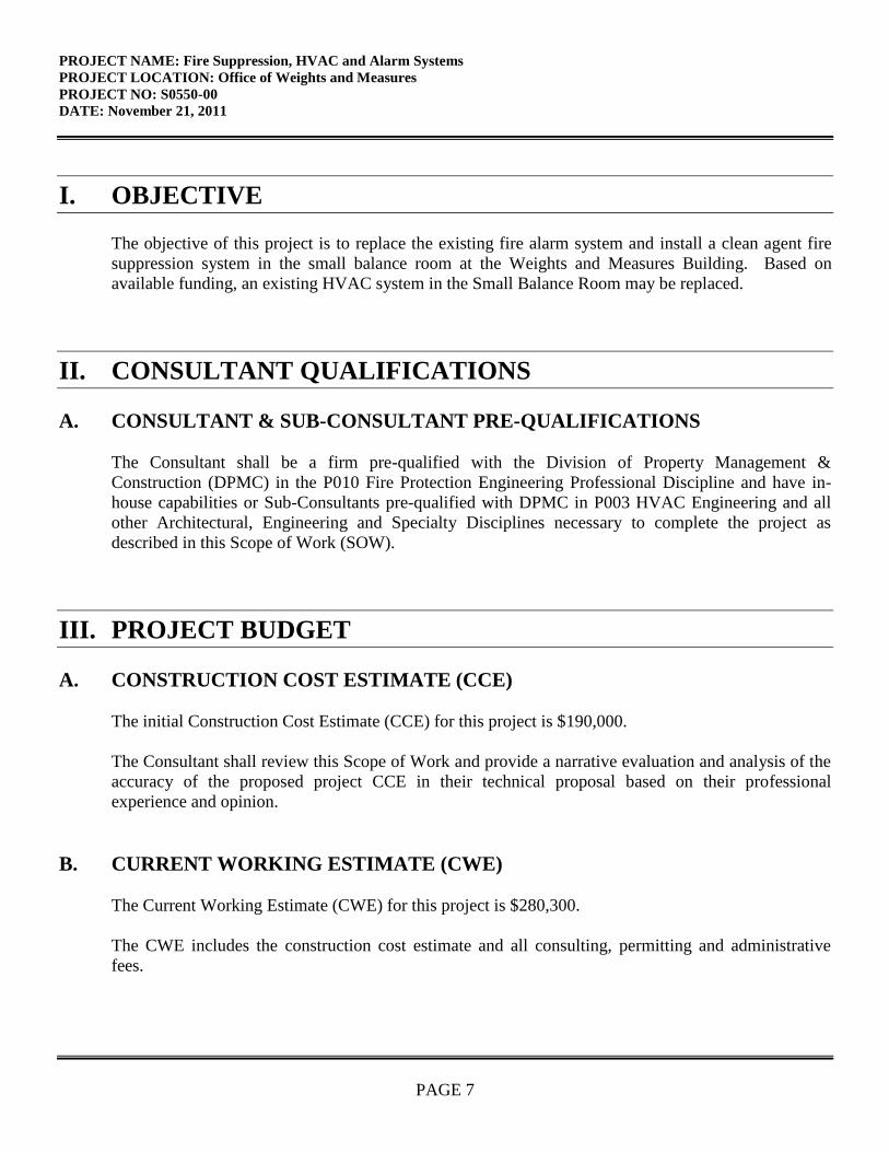
I. OBJECTIVE
The objective of this project is to replace the existing fire alarm system and install a clean agent fire
suppression system in the small balance room at the Weights and Measures Building. Based on
available funding, an existing HVAC system in the Small Balance Room may be replaced.
II. CONSULTANT QUALIFICATIONS
A. CONSULTANT & SUB-CONSULTANT PRE-QUALIFICATIONS
The Consultant shall be a firm pre-qualified with the Division of Property Management &
Construction (DPMC) in the P010 Fire Protection Engineering Professional Discipline and have in-
house capabilities or Sub-Consultants pre-qualified with DPMC in P003 HVAC Engineering and all
other Architectural, Engineering and Specialty Disciplines necessary to complete the project as
described in this Scope of Work (SOW).
III. PROJECT BUDGET
A. CONSTRUCTION COST ESTIMATE (CCE)
The initial Construction Cost Estimate (CCE) for this project is $190,000.
The Consultant shall review this Scope of Work and provide a narrative evaluation and analysis of the
accuracy of the proposed project CCE in their technical proposal based on their professional
experience and opinion.
B. CURRENT WORKING ESTIMATE (CWE)
The Current Working Estimate (CWE) for this project is $280,300.
The CWE includes the construction cost estimate and all consulting, permitting and administrative
fees.
PROJECT NAME: Fire Suppression, HVAC and Alarm Systems
PROJECT LOCATION: Office of Weights and Measures
PROJECT NO: S0550-00
DATE: November 21, 2011
PAGE 8
The CWE is the Client Agency’s financial budget based on this project Scope of Work and shall not
be exceeded during the design and construction phases of the project unless DPMC approves the
change in Scope of Work through a Contract amendment.
C. COST ESTIMATING
On projects with a CCE under $750,000, the estimate may be prepared by the Consultant’s in-house
staff or their Sub-Consultant’s staff during each design phase of the project. However, if the CCE is
$750,000 or larger, the Consultant or Sub-Consultant providing the estimate must be pre-qualified
with DPMC in the P025 Estimating/Cost Analysis Specialty Discipline.
All cost estimates shall be adjusted for regional location, site factors, construction phasing, premium
time, building use group, location of work within the building, temporary swing space, security issues,
and inflation factors based on the year in which the work is to be performed.
All cost estimates must be submitted on a DPMC-38 Project Cost Analysis form at each design phase
of the project with a detailed construction cost analysis in CSI format (2004 Edition) for all
appropriate divisions and sub-divisions. The Project Manager will provide cost figures for those items
which may be in addition to the CCE such as art inclusion, CM services, etc. and must be included as
part of the CWE. This cost analysis must be submitted for all projects regardless of the Construction
Cost Estimate amount.
D. CONSULTANT’S FEES
The construction cost estimate for this project shall not be used as a basis for the Consultant’s design
and construction administration fees. The Consultant’s fees shall be based on the information
contained in this Scope of Work document and the observations made and/or the additional
information received during the pre-proposal meeting.
PROJECT NAME: Fire Suppression, HVAC and Alarm Systems
PROJECT LOCATION: Office of Weights and Measures
PROJECT NO: S0550-00
DATE: November 21, 2011
PAGE 9
IV. PROJECT SCHEDULE
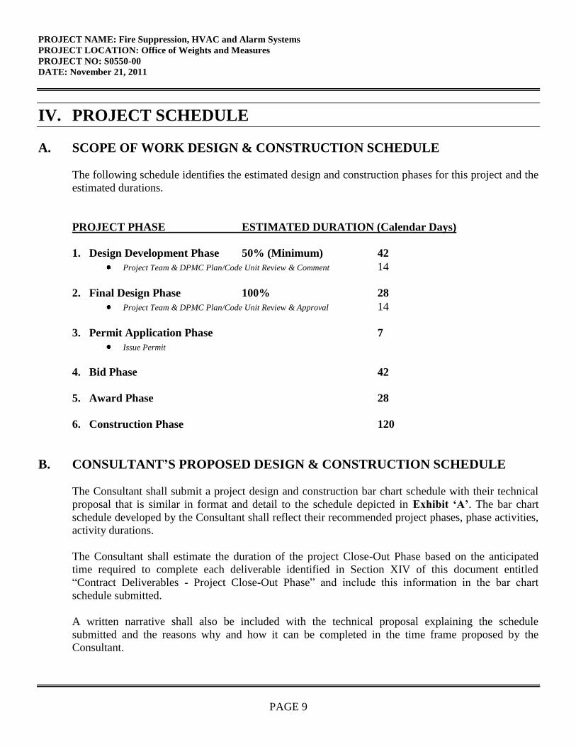
A. SCOPE OF WORK DESIGN & CONSTRUCTION SCHEDULE
The following schedule identifies the estimated design and construction phases for this project and the
estimated durations.
PROJECT PHASE ESTIMATED DURATION (Calendar Days)
1. Design Development Phase 50% (Minimum) 42
Project Team & DPMC Plan/Code Unit Review & Comment 14
2. Final Design Phase 100% 28
Project Team & DPMC Plan/Code Unit Review & Approval 14
3. Permit Application Phase 7
Issue Permit
4. Bid Phase 42
5. Award Phase 28
6. Construction Phase 120
B. CONSULTANT’S PROPOSED DESIGN & CONSTRUCTION SCHEDULE
The Consultant shall submit a project design and construction bar chart schedule with their technical
proposal that is similar in format and detail to the schedule depicted in Exhibit ‘A’. The bar chart
schedule developed by the Consultant shall reflect their recommended project phases, phase activities,
activity durations.
The Consultant shall estimate the duration of the project Close-Out Phase based on the anticipated
time required to complete each deliverable identified in Section XIV of this document entitled
“Contract Deliverables - Project Close-Out Phase” and include this information in the bar chart
schedule submitted.
A written narrative shall also be included with the technical proposal explaining the schedule
submitted and the reasons why and how it can be completed in the time frame proposed by the
Consultant.
PROJECT NAME: Fire Suppression, HVAC and Alarm Systems
PROJECT LOCATION: Office of Weights and Measures
PROJECT NO: S0550-00
DATE: November 21, 2011
PAGE 10
This schedule and narrative will be reviewed by the Consultant Selection Committee as part of the
evaluation process and will be assigned a score commensurate with clarity and comprehensiveness of
the submission.
C. CONSULTANT DESIGN SCHEDULE
The Project Manager will issue the Consultant’s approved project schedule at the first design kickoff
meeting. This schedule will be binding for the Consultant’s activities and will include the start and
completion dates for each design activity. The Consultant and Project Team members shall use this
schedule to ensure that all design milestone dates are being met for the project. The Consultant shall
update the schedule to reflect performance periodically (minimally at each design phase) for the
Project Team review and approval. Any recommendations for deviations from the approved design
schedule must be explained in detail as to the causes for the deviation(s) and impact to the schedule.
D. BID DOCUMENT CONSTRUCTION SCHEDULE
The Consultant shall include a construction schedule in Division 1 of the specification bid document.
This schedule shall contain, at minimum, the major activities and their durations for each trade
specified for the project. This schedule shall be in “bar chart” format and will be used by the
Contractors as an aid in determining their bid price. It shall reflect special sequencing or phased
construction requirements including, but not limited to: special hours for building access, weather
restrictions, imposed constraints caused by Client Agency program schedules, security needs, lead
times for materials and equipment, anticipated delivery dates for critical items, utility interruption and
shut-down constraints, and concurrent construction activities of other projects at the site and any other
item identified by the Consultant during the design phases of the project.
E. CONTRACTOR CONSTRUCTION PROGRESS SCHEDULE
The Contractor shall be responsible for preparing a coordinated combined progress schedule with the
Sub-Contractors after the award of the contract. This schedule shall meet all of the requirements
identified in the Consultant’s construction schedule. The construction schedule shall be completed in
accordance with the latest edition of the Instructions to Bidders and General Conditions entitled,
“Article 9, Construction Progress Schedule” (No CPM).
The Consultant must review and analyze this progress schedule and recommend approval/disapproval
to the Project Team until a satisfactory version is approved by the Project Team. The Project Team
must approve the baseline schedule prior to the start of construction and prior to the Contractor
submitting invoices for payment.
The Consultant shall note in Division 1 of the specification that the State will not accept the progress
schedule until it meets the project contract requirements and any delays to the start of the construction
work will be against the Contractor until the date of acceptance by the State.
PROJECT NAME: Fire Suppression, HVAC and Alarm Systems
PROJECT LOCATION: Office of Weights and Measures
PROJECT NO: S0550-00
DATE: November 21, 2011
PAGE 11
The construction progress schedule shall be reviewed, approved, and updated by the Contractor of
schedule, Consultant, and Project Team members at each regularly scheduled construction job meeting
and the Consultant shall note the date and trade(s) responsible for project delays (as applicable).
V. PROJECT SITE LOCATION & TEAM MEMBERS
A. PROJECT SITE ADDRESS
The location of the project site is:
Office of Weights and Measures
1261 Routes 1 and 9 South
Avenel, NJ 07001
See Exhibit ‘B’ for the project site map.
B. PROJECT TEAM MEMBER DIRECTORY
The following are the names, addresses, and phone numbers of the Project Team members.
1. DPMC Representative:
Name: Nurul Hasan, Project Manager
Address: Division Property Management & Construction
20 West State Street, 3rd
Floor
Trenton, NJ 08625
Phone No: (609) 633-8265, Fax: (609) 984-1750
E-Mail No: [email protected]
2. Client Agency Representative:
Name: Charles Hreha, Project Manager
Address: Department of Law and Public Safety
Office of the Attorney General, Facilities Services
25 Market Street, 3rd
Floor West Wing
P.O. Box 081
Trenton, NJ 08625-0081
Phone No: (609) 984-6999, Fax: (609) 341-3040
E-Mail No: [email protected]
PROJECT NAME: Fire Suppression, HVAC and Alarm Systems
PROJECT LOCATION: Office of Weights and Measures
PROJECT NO: S0550-00
DATE: November 21, 2011
PAGE 12
VI. PROJECT DEFINITION
A. BACKGROUND
The Office of Weights and Measures is responsible for ensuring that all commercial weighing and
measuring devices accurately measure the commodities sold to consumers. The office also oversees
the operations of the county and local weights and measures offices.
The State of New Jersey Department of Law and Public Safety obtained the services of Jacobs
Architects/Engineers, Inc. in March 2011 to conduct a study of the existing fire alarm and fire
protection system within the building. The study focused on three areas: upgrading or replacing the
existing fire alarm system, installing a clean agent fire suppression system in the Small Balance(Small
Scales) Room, and extending the existing limited sprinkler system. The priorities for this project are
replacing the existing fire alarm system and installing a clean agent fire suppression system in the
Small Balance Room. Extending the sprinkler system is not required by code and will not be a part of
this project. The study report from Jacobs is in Exhibit ‘D’.
One area not covered in the study is the HVAC system for the Small Balance room. The Small
Balance Room has a separate system for maintaining the temperature and humidity in the room. The
facility management would like to replace the existing HVAC system for the room. This will require
an evaluation with cost estimates. An allowance will be created for design of the HVAC system and it
will be bid as an add alternate.
B. FUNCTIONAL DESCRIPTION OF THE BUILDING
The Office of Weights and Measures is housed in a mostly single story structure with an office area,
lab wing and truck wing. A stairwell off the boiler room provides access to an equipment room and a
calibration station area on different levels of the truck wing.
The main fire alarm panel is located in the boiler room. The remote annunciator panel is located in the
main lobby. The existing fire alarm system is non-addressable. A more complete description can be
found in the study report from Jacobs in Exhibit ‘D’.
The Small Balance(Small Scales) Room contains the sensitive scales and equipment used to compare
samples against standards. It is roughly 16’ X 28’ in size. The HVAC system for the room is located
above the room in the ceiling. Space for storage tanks containing clean agent chemicals should be
available in environmental control room #1 next door.
PROJECT NAME: Fire Suppression, HVAC and Alarm Systems
PROJECT LOCATION: Office of Weights and Measures
PROJECT NO: S0550-00
DATE: November 21, 2011
PAGE 13
VII. CONSULTANT DESIGN RESPONSIBILITIES
The Consultant shall review the report from Jacobs Architects/Engineers, Inc. shown in Exhibit ‘D’
and provide the design and specifications necessary to replace the existing fire alarm system and
install a clean agent fire suppression system in the Small Scales Room.
A. FIRE DETECTION SYSTEM
Provide a design for a new addressable fire alarm system, panels, fire detection system components
and devices for the entire building as recommended in the Jacobs report.
The annunciator panel shall be placed in the building in a location acceptable to the client.
The design documents shall provide sufficient detail of the new fire detection systems. All fire
detection and related suppression system components shall be shown on the drawings.
Provide wiring diagrams of the fire detection system indicating the zoning, the grouping of devices
and the number of wires to each device. All wiring shall be color coded and identified by number at
termination points and splice points and a color coding schedule shall be submitted to the DPMC
Project Manager by the Contractor for approval prior to installation.
The new system shall have a five year warranty on all parts and a one year free maintenance contract
on all system components.
The new fire alarm signals shall be separate from the existing security system.
The Consultant shall make a recommendation as to whether or not the existing fire detection system
must remain operational during the installation of new detection system.
B. CLEAN AGENT SYSTEM
The following information is intended to be used as a guide by the Consultant during the design of the
new fire suppression system. Specific design details shall be obtained from the current edition of
NFPA 2001 “Clean Agent Fire Extinguishing Systems”.
1. Agent Supply:
Provide a description of the agent storage container(s) required including the agent being used, internal
volume, storage pressure, and nominal capacity expressed in units of agent mass or volume at standard
conditions of temperature and pressure.
PROJECT NAME: Fire Suppression, HVAC and Alarm Systems
PROJECT LOCATION: Office of Weights and Measures
PROJECT NO: S0550-00
DATE: November 21, 2011
PAGE 14
Investigate and provide a plan to install the agent container(s) in a cost effective and practical location
such as the Environmental Control Room.
2. Detection, Actuation, Alarms and Control Systems:
Provide a schematic drawing showing the location and tie in method of all fire detection, actuation,
alarms, and control systems to be provided in the Small Balance Room.
Provide a schematic drawing showing the tie in method of all detectors, actuation devices, alarms, and
control systems to the new fire alarm control panel.
Provide a complete step by step description of the system sequence of operations including
functioning of abort and maintenance switches, delay timers, and emergency power shutdown.
3. Design Documents:
Provide detailed drawings showing the room and agent distribution system including the agent storage
container location, piping and nozzle locations, type of pipe hangers and rigid pipe supports, detection,
alarm, and control systems including all devices and schematics of wiring interconnection between
them, end-of-line device locations, location of controlled devices such as dampers and shutters, and
location of instructional signage.
4. System Flow Calculations:
System flow calculations shall be performed and one (1) signed and sealed set submitted to the DPMC
Code and Design Unit Manager for record. The version of the flow calculation program shall be
identified on the computer calculation documentation provided.
5. Small Balance Room Enclosure:
Provide a cross section of the room showing the construction of the building floor and ceiling systems.
Provide a description of the occupancies and hazards being protected, designating if the room is
normally occupied.
Appropriate room openings shall be permanently sealed or equipped with automatic closures to
prevent loss of agent through openings to adjacent work areas. Forced air ventilation systems shall be
shut down or closed automatically where their continued operation would adversely affect the
performance of the fire extinguishing system or result in propagation of the fire. Completely self
contained re-circulating ventilation systems shall not be required to be shut down.
Investigate the need for ceiling tile clips to be used with the new fire suppression system.
PROJECT NAME: Fire Suppression, HVAC and Alarm Systems
PROJECT LOCATION: Office of Weights and Measures
PROJECT NO: S0550-00
DATE: November 21, 2011
PAGE 15
6. Distribution System:
Provide an isometric view of the agent distribution system showing the length and diameter of each
pipe segment; node reference numbers relating to the flow calculations, valves and operating devices,
fittings including reducers and strainers, and orientation of tees, nozzles including size, orifice port
configuration, flow rate, and equivalent orifice area.
7. Nozzle Choice and Location:
Determine and provide the most cost effective and practical method to install the fire suppression
system in the room.
8. Pre-Action System:
Not mentioned in the Jacobs report is the idea of backing up the clean agent system with a double
interlock pre-action fire suppression system. Provide the design and specifications to install this pre-
action system as a back-up to the clean agent system. Flow tests will not be required for this system if
sprinklers are not extended to the rest of the building (see below).
C. HVAC SYSTEM
1. Investigation:
The Consultant, or Sub-Consultant, pre-qualified with DPMC in the P003 HVAC Design Professional
Discipline shall investigate the costs associated with designing and constructing a new HVAC system
for the Small Balance Room. Provide a written report to the project team detailing the results of the
investigation. The costs associated with conducting the investigation shall be part of the Consultant’s
lump sum fee.
2. Design:
Should a design be needed, items to consider shall include the following:
The design shall include signed and sealed heating and cooling load calculations provided to the
DPMC Design & Code Review Unit that will substantiate the recommended size of the new system.
The system shall be designed to maintain temperature and humidity requirements for the measurement
functions in the room.
Provide appropriate drawings showing the ducting for the new HVAC system and any related
auxiliary equipment. Include all symbol legends on the drawings. Specify the requirements for all
hangers, supports, equipment and insulation, identification tags, descriptive labels, thermostats, gages,
etc.
PROJECT NAME: Fire Suppression, HVAC and Alarm Systems
PROJECT LOCATION: Office of Weights and Measures
PROJECT NO: S0550-00
DATE: November 21, 2011
PAGE 16
Provide an electrical riser diagram showing the location and type of electrical system components for
the new HVAC system, controls, and related auxiliary equipment. Show the proper tie in of all
electrical components to their system circuitry and electrical supply. Include all wire sizes, current
demand factors, equipment ratings, panel schedules, and symbol legends on the drawings.
Identify and purchase any manufacturer’s recommended spare parts and special tools or instruments
needed for the operation or maintenance of the equipment as part of this project.
Specify an appropriate manufacturer’s warranty for the entire system, including the controls, auxiliary
equipment, hardware, and related components.
It is intended that the building will be occupied during the construction phase of this project and the
security and daily operation of the building must be maintained at all times. The Consultant shall
identify the need to vacate the building during demolition or construction, if necessary. The
equipment demolition and installation procedures will have to be described in the design documents
including, but not limited to: allowable utility shutdown and switchover durations, requirements for
temporary isolation valves and bypass piping for equipment, temporary power and utility backup
systems, fire department notifications, etc.
3. HVAC System Design Allowance:
The Consultant or Sub-Consulting firm selected by the Consultant to prepare the design documents,
and provide construction administration services to replace the HVAC system described above shall
estimate all of the costs associated with the work and submit that amount to the Consultant prior to the
proposed due date.
The Consultant shall enter the amount submitted by the Sub-Consulting firm(s) on the fee proposal
line item entitled “HVAC System Design Allowance” and attach a detailed cost breakdown sheet for
use by DPMC during the proposal review and potential fee negotiations.
Any funds remaining in the allowance account will be returned to the State at the close of the project.
The design for the HVAC system replacement shall be bid as an “Add Alternate” and will be
awarded based on available project funding.
D. INSPECTION, TESTING AND TRAINING
1. System Test:
Upon completion of the project and prior to issuance of the Certificate of Approval, the Contractor
shall employ the services of a Certified Testing Lab to inspect and test the completed fire suppression
and detection systems, as applicable, making adjustments as required to secure all necessary
PROJECT NAME: Fire Suppression, HVAC and Alarm Systems
PROJECT LOCATION: Office of Weights and Measures
PROJECT NO: S0550-00
DATE: November 21, 2011
PAGE 17
approvals. The Consultant shall identify the testing requirements in the specification including the test
pressures, the test duration under pressure, and the amount of allowable leakage per hour.
All equipment testing shall be conducted in the presence of the DPMC Project Team members, DPMC
Design & Code Review Unit Representative, Consultant, Contractors, and DCA code official. The
Consultant shall be responsible for the coordination and scheduling of all tests. All test results shall be
collected and bound in a manual for reference.
2. Spare Parts:
A spare parts list shall be prepared and items purchased as part of this project, as applicable, for all
critical items necessary for the successful operation of the fire detection and suppression systems such
as nozzles, detectors, fire alarm fuses, switches, relays, LED lights, etc. Include one type of each type
of valve in the spare parts list.
3. System Training:
Coordinate the system training of the new fire detection and suppression systems with the designated
Client Agency personnel and equipment vendors. Manuals shall be issued that contain the operating
procedures, parts lists, detailed drawings, catalog cuts, and maintenance procedures for all equipment
installed in the buildings.
The content of the manuals and training sessions, and the length of the training sessions shall be
reviewed and approved by the DPMC Project Team members prior to the training seminar.
E. GENERAL DESIGN OVERVIEW
1. Design Detail:
Section VII of this Scope of Work is intended as a guide for the Consultant to understand the overall
basic design requirements of the project and is not intended to identify each specific design component
related to code and construction items. The Consultant shall provide those details during the design
phase of the project ensuring that they are in compliance with all applicable codes, regulating
authorities, and the guidelines established in the DPMC Procedures for Architects and Engineers
Manual.
The Consultant shall understand that construction documents submitted to DPMC shall go beyond the
basic requirements set forth by the current copy of the Uniform Construction Code NJAC 5:23-2.15(f).
Drawings and specifications shall provide detail beyond that required to merely show the nature and
character of the work to be performed. The construction documents shall provide sufficient
information and detail to illustrate, describe and clearly delineate the design intent of the Consultant
and enable all Contractors to uniformly bid the project.
PROJECT NAME: Fire Suppression, HVAC and Alarm Systems
PROJECT LOCATION: Office of Weights and Measures
PROJECT NO: S0550-00
DATE: November 21, 2011
PAGE 18
The Consultant shall ensure that all of the design items described in this scope of work are addressed
and included in the project drawings and specification sections where appropriate.
It shall be the Consultant’s responsibility to provide all of the design elements for this project. Under
no circumstance may they delegate the responsibility of the design; or portions thereof, to the
Contractor unless specifically allowed in this Scope of Work.
2. Specification Format:
The Consultant shall ensure that the project design specifications are formatted in the revised and
expanded version of the Construction Specifications Institute (CSI) format entitled “Master Format
2004 Edition: Numbers and Titles.”
The Consultant shall review all of the CSI Master Format 2004 specification sections listed and
remove those that do not apply and edit those that remain so they are consistent and specific to this
project scope of work.
F. PROJECT COMMENCEMENT
A pre-design meeting shall be scheduled with the Consultant and the Project Team members at the
commencement of the project to obtain and/or coordinate the following information:
1. Project Directory:
Develop a project directory that identifies the name and phone number of key designated
representatives who may be contacted during the design and construction phases of this project.
2. Site Access:
Develop procedures to access the project site and provide the names and phone numbers of approved
escorts when needed. Obtain copies of special security and policy procedures that must be followed
during all work conducted at the facility and include this information in Division 1 of the specification.
3. Project Coordination:
Review and become familiar with any current and/or future projects at the site that may impact the
design, construction, and scheduling requirements of this project. Incorporate all appropriate
information and coordination requirements in Division 1 of the specification.
4. Existing Documentation:
Copies of the as-built drawings for the building will be provided to each Consulting firm at the pre-
proposal meeting to assist in the bidding process.
PROJECT NAME: Fire Suppression, HVAC and Alarm Systems
PROJECT LOCATION: Office of Weights and Measures
PROJECT NO: S0550-00
DATE: November 21, 2011
PAGE 19
Review these drawings and any additional information that may be provided at a later date such as
reports, studies, surveys, equipment manuals, etc. The State does not attest to the accuracy of the
information provided and accepts no responsibility for the consequences of errors by the use of any
information and material contained in the documentation provided. It shall be the responsibility of the
Consultant to verify the contents and assume full responsibility for any determination or conclusion
drawn from the material used. If the information provided is insufficient, the Consultant shall take the
appropriate actions necessary to obtain the additional information required.
All original documentation shall be returned to the provider at the completion of the project.
5. Scope of Work:
Review the design and construction administration responsibilities and the submission requirements
identified in this Scope of Work with the Project Team members. Items such as: contract
deliverables, special sequencing or phased construction requirements, special hours for construction
based on Client Agency programs or building occupancy, security needs, delivery dates of critical and
long lead items, utility interruptions or shut down constraints for tie-ins, weather restrictions, and
coordination with other project construction activities at the site shall be addressed.
This information and all general administrative information; including a narrative summary of the
work for this project, shall be included in Division 1 of the specification. The Consultant shall assure
that there are no conflicts between the information contained in Division 1 of the specification and the
DPMC General Conditions.
6. Project Schedule:
Review and update the project design and construction schedule with the Project Team members.
G. BUILDING & SITE INFORMATION
The following information shall be included in the project design documents.
1. Building Classification:
Provide the building Use Group Classification and Construction Type on the appropriate design
drawing.
2. Building Block & Lot Number:
Provide the site Block and Lot Number on the appropriate design drawing.
PROJECT NAME: Fire Suppression, HVAC and Alarm Systems
PROJECT LOCATION: Office of Weights and Measures
PROJECT NO: S0550-00
DATE: November 21, 2011
PAGE 20
3. Building Site Plan:
Only when the project scope involves site work, or when the design triggers code issues that require
site information to show code compliance, shall a site plan be provided that is drawn in accordance
with an accurate boundary line survey. The site plan shall include, but not be limited to, the following
as may be applicable:
The size and location of new and existing buildings and additions as well as other structures.
The distance between buildings and structures and to lot lines.
Established and new site grades and contours as well as building finished floor elevations.
New and existing site utilities, site vehicular and pedestrian roads, walkways and parking areas.
4. Site Location Map:
Provide a site location map on the drawing cover sheet that identifies the vehicular travel routes from
major roadways to the project construction site and the approved access roads to the Contractor’s
worksite staging area.
H. DESIGN MEETINGS & PRESENTATIONS
1. Design Meetings:
Conduct the appropriate number of review meetings with the Project Team members during each
design phase of the project so they may determine if the project meets their requirements, question any
aspect of the contract deliverables, and make changes where appropriate. The Consultant shall
describe the philosophy and process used in the development of the design criteria and the various
alternatives considered to meet the project objectives. Selected studies, sketches, cost estimates,
schedules, and other relevant information shall be presented to support the design solutions proposed.
Special considerations shall also be addressed such as: Contractor site access limitations, utility
shutdowns and switchover coordination, phased construction and schedule requirements, security
restrictions, available swing space, material and equipment delivery dates, etc.
It shall also be the responsibility of the Consultant to arrange and require all critical Sub-Consultants
to be in attendance at the design review meetings.
Record the minutes of each design meeting and distribute within seven (7) calendar days to all
attendees and those persons specified to be on the distribution list by the Project Manager.
2. Design Presentations:
The minimum number of design presentations required for each phase of this project is identified
below for reference:
PROJECT NAME: Fire Suppression, HVAC and Alarm Systems
PROJECT LOCATION: Office of Weights and Measures
PROJECT NO: S0550-00
DATE: November 21, 2011
PAGE 21
Design Development Phase: One (1) oral presentation at phase completion.
Final Design Phase: One (1) oral presentation at phase completion.
VIII.CONSULTANT CONSTRUCTION RESPONSIBILITIES
A. GENERAL CONSTRUCTION ADMINISTRATION OVERVIEW
This section of the Scope of Work is intended as a guide for the Consultant to understand their overall
basic construction administration responsibilities for the project and does not attempt to identify each
specific activity or deliverable required during this phase. The Consultant shall obtain that information
from the current publication of the DPMC Procedures for Architects and Engineers Manual and any
additional information provided during the Consultant Selection Process.
B. PRE-BID MEETING
The Consultant shall attend, chair, record and distribute minutes of the Contractor pre-bid meetings.
When bidders ask questions that may affect the bid price of the project, the Consultant shall develop a
Bulletin(s) to clarify the bid documents in the format described in the Procedures for Architects and
Engineers Manual, Section 9.2 entitled “Bulletins.” These Bulletins must be sent to DPMC at least
seven (7) calendar days prior to the bid opening date. DPMC will then distribute the document to all
bidders.
C. BID OPENING
The Consultant must attend the bid opening held at the designated location.
In the event that the construction bids received exceed the Consultant’s approved final cost estimate by
5% or more, the Consultant shall redesign and/or set up sufficient approved alternate designs, plans
and specifications for the project work, to secure a bid that will come within the allocation specified
by the State without impacting the programmatic requirements of the project. Such redesign work and
changes to plans, including reproduction costs for submission in order to obtain final approval and
permits, shall be undertaken by the Consultant at no additional cost to the State.
D. POST BID REVIEW MEETING, RECOMMENDATION FOR AWARD
The Consultant; in conjunction with the Project Manager, shall review the bid proposals submitted by
the various Contractors to determine the low responsible bid for the project. The Consultant; in
conjunction with the Project Manager, shall develop a post bid questionnaire based on the
requirements below and schedule a post bid review meeting with the Contractor’s representative to
PROJECT NAME: Fire Suppression, HVAC and Alarm Systems
PROJECT LOCATION: Office of Weights and Measures
PROJECT NO: S0550-00
DATE: November 21, 2011
PAGE 22
review the construction costs and schedule, staffing, and other pertinent information to ensure they
understand the Scope of the Work and that their bid proposal is complete and inclusive of all
requirements necessary to deliver the project in strict accordance with the plans and specifications.
1. Post Bid Review:
Review the project bid proposals including the alternates, unit prices, and allowances within seven (7)
calendar days from the bid due date. Provide a bid tabulation matrix comparing all bids submitted and
make a statement about the high, low, and average bids received. Include a comparison of the
submitted bids to the approved current construction cost estimate. When applicable, provide an
analysis with supporting data, detailing why the bids did not meet the construction cost estimate.
2. Review Meeting:
Arrange a meeting with the apparent low bid Contractor to discuss their bid proposal and other issues
regarding the award of the contract. Remind the Contractor that this is a Lump Sum bid. Request the
Contractor to confirm that their bid proposal does not contain errors. Review and confirm Alternate
pricing and Unit pricing and document acceptance or rejection as appropriate.
Comment on all omissions, qualifications and unsolicited statements appearing in the proposals.
Review any special circumstances of the project. Ensure the Contractor’s signature appears on all post
bid review documents.
3. Substitutions:
Inquire about any potential substitutions being contemplated by the Contractor and advise them of the
State’s guidelines for the approval of substitutions and the documentation required. Review the
deadline and advise the Contractor that partial submissions are not acceptable. Submission after the
deadline may be rejected by the State.
Equal substitutions that are proposed by the Contractor that are of lesser value must have a credit
change order attached with the submittal (See Article 4 of the General Conditions). The State has the
right to reject the submission if there is no agreement on the proposed credit. Contractor will be
responsible to submit a specified item.
4. Schedule:
Confirm that the Contractor is aware of the number of calendar days listed in the contract documents
for the project duration and that the Contractor’s bid includes compliance with the schedule duration
and completion dates. Particular attention shall be given to special working conditions, long lead items
and projected delivery dates, etc. Review project milestones (if applicable). This could give an
indication of Contractor performance, but not allow a rejection of the bid.
PROJECT NAME: Fire Suppression, HVAC and Alarm Systems
PROJECT LOCATION: Office of Weights and Measures
PROJECT NO: S0550-00
DATE: November 21, 2011
PAGE 23
Review the submittal timeframes per the Contract documents. Ask the Contractor to identify what
products will take over twenty-eight (28) calendar days to deliver from the point of submittal approval.
5. Performance:
Investigate the past performance of Contractor by contacting Architects and owners (generally three of
each) that were listed in their DPMC pre-qualification package and other references that may have
been provided. Inquire how the Contractor performed with workmanship, schedule, project
management, change orders, cooperation, paper work, etc.
6. Superintendent:
Remind the Contractor that a full-time non-working superintendent is required per the General
Conditions, who must be responsible to address Contract issues. (Article 4.3.2.).
7. Letter of Recommendation:
The Consultant shall prepare a Letter of Recommendation for contract award to the Contractor
submitting the low responsible bid within three (3) calendar days from the post bid review meeting.
The document shall contain the project title, DPMC project number, bid due date and expiration date
of the proposal. It shall include a detailed narrative describing each post bid meeting agenda item
identified above and a recommendation to award the contract to the apparent low bid Contractor based
on the information obtained during that meeting. Describe any acceptance or rejection of Alternate
pricing and Unit pricing.
Comment on any discussion with the Contractor that provides a sense of their understanding of the
project and any special difficulties that they see, and how they might approach those problems.
Attach all minutes of the Post bid meeting and any other relevant correspondence with the Letter of
Recommendation and submit them to the Project Manager.
8. Conformed Drawings:
The Consultant shall prepare and distribute two (2) sets of drawings stamped “Conformed Drawings”
to the Project Manager that reflect all Bulletins and/or required changes, additions, and deletions to the
pertinent drawings within twenty-eight (28) calendar days of the construction contract award date.
Any changes made in Bulletins, meeting minutes, post bid review requirements shall also be reflected
in the specification.
PROJECT NAME: Fire Suppression, HVAC and Alarm Systems
PROJECT LOCATION: Office of Weights and Measures
PROJECT NO: S0550-00
DATE: November 21, 2011
PAGE 24
E. DIRECTOR’S HEARING
The Consultant must attend any Director’s hearing(s) if a Contractor submits a bid protest. The
Consultant shall be present to interpret the intent of the design documents and answer any technical
questions that may result from the meeting. In cases where the bid protest is upheld, the Consultant
shall submit a new “Letter of Recommendation” for contract award. The hours required to attend the
potential hearings and to document the findings shall be estimated by the Consultant and the costs will
be included in the base bid of their fee proposal.
F. CONSTRUCTION JOB MEETINGS, SCHEDULES, LOGS
The Consultant shall conduct all of the construction job meetings in accordance with the procedures
identified in the A/E manual and those listed below.
1. Meetings:
The Consultant and Sub-Consultant(s) shall attend the pre-construction meeting and all construction
job meetings during the construction phase of the project. The Consultant shall chair the meeting,
transcribe and distribute the job-meeting minutes for every job meeting to all attendees and to those
persons specified to be on the distribution list by the Project Manager. The Agenda for the meeting
shall include, but not be limited to the items identified in the Procedures for Architects and Engineers
Manual, Section 10.3.1, entitled “Agenda.”
Also, the Consultant is responsible for the preparation and distribution of minutes within three (3)
calendar days of the meeting. The format to be used for the minutes shall comply with those identified
in the “Procedures for Architects and Engineers Manual,” Section 10.3.4, entitled, “Format of
Minutes.” All meeting minutes are to have an “action” column indicating the party that is responsible
for the action indicated and a deadline to accomplish the assigned task. These tasks must be reviewed
at each job progress meeting until it is completed and the completion date of each task shall be noted
in the minutes of the meeting following the task completion.
2. Schedules:
The Consultant; with the input from the Client Agency Representative and Project Manager, shall
review and recommend approval of the project construction schedule prepared by the Contractor. The
schedule shall identify all necessary start and completion dates of construction, construction activities,
submittal process activities, material deliveries and other milestones required to give a complete
review of the project.
The Consultant shall record any schedule delays, the party responsible for the delay, the schedule
activity affected, and the original and new date for reference.
PROJECT NAME: Fire Suppression, HVAC and Alarm Systems
PROJECT LOCATION: Office of Weights and Measures
PROJECT NO: S0550-00
DATE: November 21, 2011
PAGE 25
The Consultant shall ensure that the Contractor provides a two (2) week “look ahead” construction
schedule based upon the current monthly updated schedule as approved at the bi-weekly job meetings
and that identifies the daily planned activities for that period. This Contractor requirement must also
be included in Division 1 of the specification for reference.
3. Submittal Log:
The Consultant shall develop and implement a submittal log that will identify all of the required
project submittals as identified in the design specification. The dates of submission shall be
determined and approved by all affected parties during the pre-construction meeting.
Examples of the submissions to be reviewed and approved by the Consultant and Sub-Consultant (if
required) include: shop drawings, change orders, Request for Information (RFI), equipment and
material catalog cuts, spec sheets, product data sheets, MSDS material safety data sheets, specification
procedures, color charts, material samples, mock-ups, etc. The submittal review process must be
conducted at each job progress meeting and shall include the Consultant, Sub-Consultant, Contractor,
Project Manager, and designated representatives of the Client Agency.
The Consultant shall provide an updated submittal log at each job meeting that highlights all of the
required submissions that are behind schedule during the construction phase of the project.
G. CONSTRUCTION SITE ADMINISTRATION SERVICES
The Consultant and Sub-Consultant(s) shall provide construction site administration services during
the duration of the project. The Consultant and Sub-Consultant(s) do not necessarily have to be on site
concurrently if there are no critical activities taking place that require the Sub-Consultant’s
participation.
The services required shall include, but not be limited to; field observations sufficient to verify the
quality and progress of construction work, conformance and compliance with the contract documents,
and to attend/chair meetings as may be required by the Project Manager to resolve special issues.
A field observation visit may be conducted in conjunction with regularly scheduled construction job
meetings, depending on the progress of work. The Consultant and their Sub-Consultant(s) shall
submit a field observation report for each site inspection to the Project Manager. Also, they shall
conduct inspections during major construction activities including, but not limited to the following
examples: concrete pours, steel and truss installations, code inspections, final testing of systems,
achievement of each major milestone required on the construction schedule, and requests from the
Project Manager. The assignment of a full time on-site Sub-Consultant does not relieve the Consultant
of their site visit obligation.
PROJECT NAME: Fire Suppression, HVAC and Alarm Systems
PROJECT LOCATION: Office of Weights and Measures
PROJECT NO: S0550-00
DATE: November 21, 2011
PAGE 26
The Consultant shall refer to Section XIV. Contract Deliverables of this Scope of Work subsection
entitled “Construction Phase” to determine the extent of services and deliverables required during this
phase of the project.
H. SUB-CONSULTANT PARTICIPATION
It is the responsibility of the Consultant to ensure that they have provided adequate hours and/or time
allotted in their technical proposal so that their Sub-Consultants may participate in all appropriate
phases and activities of this project or whenever requested by the Project Manager. This includes the
pre-proposal site visit and the various design meetings and construction job meetings, site visits, and
close-out activities described in this Scope of Work. Field observation reports and/or meeting minutes
are required to be submitted to the Project Manager within three (3) calendar days of the site visit or
meeting. All costs associated with such services shall be included in the base bid of the Consultant’s
fee proposal.
I. DRAWINGS
1. Shop Drawings:
Each Contractor shall review the specifications and determine the numbers and nature of each shop
drawing submittal. Five (5) sets of the documents shall be submitted with reference made to the
appropriate section of the specification. The Consultant shall review the Contractor’s shop drawing
submissions for conformity with the construction documents within fourteen (14) calendar days of
receipt. The Consultant shall return each shop drawing submittal stamped with the appropriate action,
i.e. “Approved”, “Approved as Noted”, “Approved as Noted Resubmit for Records”, “Rejected”, etc.
2. As-Built & Record Set Drawings:
The Contractor(s) shall keep the contract drawings up-to-date at all times during construction and
upon completion of the project, submit their AS-BUILT drawings to the Consultant with the
Contractor(s) certification as to the accuracy of the information prior to final payment. All AS-BUILT
drawings submitted shall be entitled AS-BUILT above the title block and dated.
The Consultant shall review the Contractor(s)’ AS-BUILT drawings at each job progress meeting to
ensure that they are up-to-date. Any deficiencies shall be noted in the progress meeting minutes.
The Consultant shall acknowledge acceptance of the AS-BUILT drawings by signing a transmittal
indicating they have reviewed them and that they reflect the AS-BUILT conditions as they exist.
Upon receipt of the AS-BUILT drawings from the Contractor(s), The Consultant shall obtain the
original mylars from DPMC and transfer the AS-BUILT conditions to the original full sized signed
mylars to reflect RECORD conditions within twenty-eight (28) calendar days of receipt of the AS-
BUILT information.
PROJECT NAME: Fire Suppression, HVAC and Alarm Systems
PROJECT LOCATION: Office of Weights and Measures
PROJECT NO: S0550-00
DATE: November 21, 2011
PAGE 27
The Consultant shall note the following statement on the original RECORD-SET drawings. “The AS-
BUILT information added to this drawing(s) has been supplied by the Contractor(s). The (Architect)
(Engineer) does not assume the responsibility for its accuracy other than conformity with the design
concept and general adequacy of the AS-BUILT information to the best of the (Architect’s)
(Engineer’s) knowledge.”
Upon completion, The Consultant shall deliver the RECORD-SET original mylars to DPMC who will
acknowledge their receipt in writing. This hard copy set of drawings and three (3) sets of current
release AUTO CAD discs shall be submitted to DPMC and the discs shall contain all AS-BUILT
drawings in both “.dwg” (native file format for AUTO CAD) and “.tif” (Tagged Image File) file
formats.
J. CONSTRUCTION DEFICIENCY LIST
The Consultant shall prepare, maintain and continuously distribute an on-going deficiency list to the
Contractor, Project Manager, and Client Agency Representative during the construction phase of the
project. This list shall be separate correspondence from the field observation reports and shall not be
considered as a punch list.
K. INSPECTIONS: SUBSTANTIAL & FINAL COMPLETION
The Consultant and their Sub-Consultant(s) accompanied by the Project Manager, Code Inspection
Group, Client Agency Representative and Contractor shall conduct site inspections to determine the
dates of substantial and final completion. The Project Manager will issue the only recognized official
notice of substantial completion. The Consultant shall prepare and distribute the coordinated punch
list, written warranties and other related DPMC forms and documents, supplied by the Contractor, to
the Project Manager for review and certification of final contract acceptance.
If applicable, the punch list shall include a list of attic stock and spare parts.
L. CLOSE-OUT DOCUMENTS
The Consultant shall review all project close-out documents as submitted by the Contractors to ensure
that they comply with the requirements listed in the “Procedure for Architects and Engineers’
Manual.” The Consultant shall forward the package to the Project Manager within twenty-eight (28)
calendar days from the date the Certificate of Occupancy/Certificate of Approval is issued. The
Consultant shall also submit a letter certifying that the project was completed in accordance with the
contract documents, etc.
PROJECT NAME: Fire Suppression, HVAC and Alarm Systems
PROJECT LOCATION: Office of Weights and Measures
PROJECT NO: S0550-00
DATE: November 21, 2011
PAGE 28
M. CLOSE-OUT ACTIVITY TIME
The Consultant shall provide all activities and deliverables associated with the “Close-Out Phase” of
this project as part of their Lump Sum base bid. The Consultant and/or Sub-Consultant(s) may not use
this time for additional job meetings or extended administrative services during the Construction Phase
of the project.
N. TESTING, TRAINING, MANUALS, AND ATTIC STOCK
The Consultant shall ensure that all equipment testing, training sessions and equipment manuals
required for this project comply with the requirements identified below.
1. Testing:
All equipment and product testing conducted during the course of construction is the responsibility of
the Contractor. However, the Consultant shall ensure the testing procedures comply with
manufacturers recommendations. The Consultant shall review the final test reports and provide a
written recommendation of the acceptance/rejection of the material, products or equipment tested
within fourteen (14) calendar days of receipt of the report.
2. Training:
The Consultant shall include in the specification that the Contractor shall schedule and coordinate all
equipment training with the Project Manager and Client Agency representatives. It shall state that the
Contractor shall submit the Operation and Maintenance (O&M) manuals, training plan contents, and
training durations to the Consultant, Project Manager and Client Agency Representative for review
and approval prior to the training session.
All costs associated with the training sessions shall be borne by the Contractor installing the
equipment. A signed letter shall be prepared stating when the training was completed and must be
accompanied with the training session sign-in sheet as part of the project close-out package.
3. Operation & Maintenance Manuals:
The Consultant shall coordinate and review the preparation and issuance of the equipment manuals
provided by the Contractor(s) ensuring that they contain the operating procedures, maintenance
procedures and frequency, cut sheets, parts lists, warranties, guarantees, and detailed drawings for all
equipment installed at the facility.
A troubleshooting guide shall be included that lists problems that may arise, possible causes with
solutions, and criteria for deciding when equipment shall be repaired and when it must be replaced.
PROJECT NAME: Fire Suppression, HVAC and Alarm Systems
PROJECT LOCATION: Office of Weights and Measures
PROJECT NO: S0550-00
DATE: November 21, 2011
PAGE 29
Include a list of the manufacturer’s recommended spare parts for all equipment being supplied for this
project.
The Consultant shall ensure that the training session is videotaped by the Contractor. A transmittal
copy must be presented to the Project Manager who will forward the document to the Client Agency
for future reference.
A list of names, addresses and telephone numbers of the Contractors involved in the installations and
firms capable of performing services for each mechanical item shall be included. The content of the
manuals shall be reviewed and approved by the Project Manager and Client Agency Representative.
The Consultant shall include in the specification that the Contractor must provide a minimum of ten
(10) “throwaway” copies of the manual for use at the training seminar and seven (7) hardbound copies
as part of the project close-out package.
4. Attic Stock:
The Consultant shall determine and recommend whether “attic stock” should be included for all
aspects of the project. If required, the Consultant shall specify attic stock items to be included in the
project.
Prior to project close-out, the Consultant must prepare a comprehensive listing of all items for delivery
by the Contractor to the Owner and in accordance with the appropriate specification/plan section.
Items shall include, but not be limited to: training sessions, O&M manuals, as-built drawings, itemized
attic stock requirements, and manufacturer guarantees/warranties.
O. CHANGE ORDERS
The Consultant shall review and process all change orders in accordance with the contract documents
and procedures described below.
1. Consultant:
The Consultant shall prepare a detailed request for Change Order including a detailed description of
the change(s) along with appropriate drawings, specifications, and related documentation and submit
the information to the Contractor for the change order request submission. This will require the use of
the current DPMC 9b form.
2. Contractor:
The Contractor shall submit a DPMC 9b Change Order Request form to the Project Manager within
seven (7) calendar days after receiving the Change Order from the Consultant. The document shall
identify the changed work in a manner that will allow a clear understanding of the necessity for the
PROJECT NAME: Fire Suppression, HVAC and Alarm Systems
PROJECT LOCATION: Office of Weights and Measures
PROJECT NO: S0550-00
DATE: November 21, 2011
PAGE 30
change. Copies of the original design drawings, sketches, etc. and specification pages shall be
highlighted to clarify and show entitlement to the Change Order.
Copies shall be provided of job minutes or correspondence with all relative information highlighted to
show the origin of the Change Order. Supplementary drawings from the Consultant shall be included
if applicable that indicate the manner to be used to complete the changed work. A detailed breakdown
of all costs associated with the change, i.e. material, labor, equipment, overhead, Sub-Contractor work,
profit and bond, and certification of increased bond shall be provided.
If the Change Order will impact the time of the project, the Contractor shall include a request for an
extension of time. This request shall include a copy of the original approved project schedule and a
proposed revised schedule that reflects the impact on the project completion date. Documentation to
account for the added time requested shall be included to support entitlement of the request such as
additional work, weather, other Contractors, etc. This documentation shall contain dates, weather data
and all other relative information.
3. Recommendation for Award:
The Consultant shall evaluate the reason for the change in work and provide a detailed written
recommendation for approval or disapproval of the Change Order Request including backup
documentation of costs in CSI format and all other considerations to substantiate that decision.
4. Code Review:
The Consultant shall determine if the Change Order request will require Code review and shall submit
six (6) sets of signed and sealed modified drawings and specifications to the DPMC Plan & Code
Review Unit for approval, if required. The Consultant must also determine and produce a permit
amendment request if required.
5. Cost Estimate:
The Consultant shall provide a detailed cost estimate of the proposed Change Order Request, as
submitted by the Contractor, in CSI format (2004 Edition) for all appropriate divisions and sub-
divisions using a recognized estimating formula. The estimate shall then be compared with that of the
Contractor’s estimate. If any line item in the Consultant’s estimate is lower than the corresponding line
item in the Contractor’s estimate, the Consultant in conjunction with the Project Manager is to contact
the Contractor by telephone and negotiate the cost differences. The Consultant shall document the
negotiated agreement on the Change Order Request form. If the Contractor’s total dollar value changes
based on the negotiations, the Consultant shall identify the changes on the Change Order Request form
accordingly.
When recommending approval or disapproval of the change order, the Consultant shall be required to
prepare and process a Change Order package that contains at a minimum the following documents:
PROJECT NAME: Fire Suppression, HVAC and Alarm Systems
PROJECT LOCATION: Office of Weights and Measures
PROJECT NO: S0550-00
DATE: November 21, 2011
PAGE 31
DPMC 9b Change Order Request
DPMC 10 Consultant’s Evaluation of Contractor’s Change Order Request
Consultant’s Independent Detailed Cost Estimate
Notes of Negotiations
6. Time Extension:
When a Change Order Request is submitted with both cost and time factors, the Consultant’s
independent cost estimate is to take into consideration time factors associated with the changed work.
The Consultant is to compare their time element with that of the Contractor’s time request and if there
is a significant difference, the Consultant in conjunction with the Project Manager is to contact the
Contractor by telephone and negotiate the difference.
When a Change Order Request is submitted for time only, the Consultant is to do an independent
evaluation of the time extension request using a recognized scheduling formula.
Requests for extension of contract time must be done in accordance with the General Conditions
Section 14.2.2.
7. Submission:
The Consultant shall complete all of the DPMC Change Order Request forms provided and submit a
completed package to the Project Manager with all appropriate backup documentation within seven (7)
calendar days from receipt of the Contractor’s change order request. The Consultant shall resubmit the
package at no cost to the State if the change order package contents are deemed insufficient by the
Project Manager.
8. Meetings:
The Consultant shall attend and actively participate at all administrative hearings or settlement
conferences as may be called by Project Manager in connection with such Change Orders and provide
minutes of those meetings to the Project Manager for distribution.
9. Consultant Fee:
All costs associated with the potential Contractor Change Order Requests shall be anticipated by the
Consultant and included in the base bid of their fee proposal.
If the Client Agency Representative requests a scope change; and it is approved by the Project
Manager, the Consultant may be entitled to be reimbursed through an amendment and in accordance
with the requirements stated in paragraph 10.01 of this Scope of Work.
PROJECT NAME: Fire Suppression, HVAC and Alarm Systems
PROJECT LOCATION: Office of Weights and Measures
PROJECT NO: S0550-00
DATE: November 21, 2011
PAGE 32
IX. PERMITS & APPROVALS
A. REGULATORY AGENCY PERMITS
The Consultant shall comply with the following guidelines to ensure that all required permits,
certificates, and approvals required by State regulatory agencies are obtained for this project.
1. NJ Uniform Construction Code Permit:
The Consultant shall complete the NJUCC permit application and all applicable technical sub-code
sections with all technical site data listed. The Agent section of the application and certification
section of the building sub-code section shall be signed. These documents shall be forwarded to the
Project Manager who will send them to the Department of Community Affairs (DCA) and all permit
application costs will be paid by DPMC from encumbered funds for the project.
The Consultant may obtain access and copies of all NJUCC Building, Fire, Plumbing, Electrical and
Elevator permit applications at the following website: www.nj.gov/dca/codes
The project construction documents must comply with the latest adopted edition of the NJ Uniform
Construction Code that is in effect at the Final Design Phase of this project.
All other required project permits shall be obtained and paid for by the Consultant in accordance with
the procedures described in paragraph 2. below.
2. Other Regulatory Agency Permits, Certificates, and Approvals:
The Consultant shall identify and obtain all other State Regulatory Agency permits, certificates, and
approvals that will govern and affect the work described in this Scope of Work. An itemized list of
these permits, certificates, and approvals shall be included with the Consultant’s Technical Proposal
and the total amount of the application fees should be entered in the Fee Proposal line item entitled,
“Permit Fee Allowance.” See Section XIV. 6.4.8 for a preliminary list of Regulatory Agency
approvals.
The Consultant may refer to the Division of Property Management and Construction “Procedures for
Architects and Engineers Manual”, Section 6.4.8, which presents a compendium of State permits,
certificates, and approvals that may be required for this project.
The Consultant shall determine the appropriate phase of the project to submit the permit application(s)
in order to meet the approved project milestone dates.
Where reference to an established industry standard is made, it shall be understood to mean the most
recent edition of the standard unless otherwise noted. If an industry standard is found to be revoked,
PROJECT NAME: Fire Suppression, HVAC and Alarm Systems
PROJECT LOCATION: Office of Weights and Measures
PROJECT NO: S0550-00
DATE: November 21, 2011
PAGE 33
or should the standard have undergone substantial change or revision from the time that the Scope of
Work was developed, the Consultant shall comply with the most recent edition of the standard.
3. Prior Approval Certification Letters:
The issuance of a construction permit for this project may be contingent upon acquiring various prior
approvals as defined by NJAC 5:23-1.4. It is the Consultant’s responsibility to determine which prior
approvals, if any, are required. The Consultant shall submit a general certification letter to the DPMC
Plan & Code Review Unit Manager during the Permit Phase of this project that certifies all required
prior approvals have been obtained.
In addition to the general certification letter discussed above, the following specific prior approval
certification letters, where applicable, shall be submitted by the Consultant to the DPMC Plan & Code
Review Unit Manager: Soil Erosion & Sediment Control, Water & Sewer Treatment Works Approval,
Coastal Areas Facilities Review, Compliance of Underground Storage Tank Systems with NJAC 7:14
b, Pinelands Review, Compliance of Abandoned Wells with NJAC 7:9-9, Certification that all utilities
have been disconnected from structures to be demolished, Board of Health Approval for Potable Water
Wells, Health Department Approval for Septic Systems. It shall be noted that in accordance with
NJAC 5:23-2.15(a)5, a permit cannot be issued until the letter(s) of certification is received.
B. BARRIER FREE REQUIREMENTS
The Consultant, in cooperation with the Client Agency Representative, shall assure that this project
complies with the NJUCC Barrier Free Sub code where applicable.
C. STATE INSURANCE APPROVAL
The Consultant shall respond in writing to the FM Global Insurance Underwriter plan review
comments through the DPMC Plan & Code Review Unit Manager as applicable. The Consultant shall
review all the comments and modify the documents while adhering to the project’s SOW
requirements, State code requirements, schedule, budget, and Consultant fee.
D. PUBLIC EMPLOYEES OCCUPATIONAL SAFETY & HEALTH PROGRAM
A paragraph shall be included in the design documents, if applicable to this project that states:
The Contractor shall comply with all the requirements stipulated in the Public Employees
Occupational Safety & Health Program (PEOSHA) document, paragraph 12:100-13.5 entitled “Air
quality during renovation and remodeling”. The Contractor shall submit a plan demonstrating the
measures to be utilized to confine the dust, debris, and air contaminants in the renovation or
construction area of the project site to the Project Team prior to the start of construction.
The link to the document is: http://www.state.nj.us/health/eoh/peoshweb/iaqstd.pdf
PROJECT NAME: Fire Suppression, HVAC and Alarm Systems
PROJECT LOCATION: Office of Weights and Measures
PROJECT NO: S0550-00
DATE: November 21, 2011
PAGE 34
E. MULTI-BUILDING OR MULTI-SITE PERMITS
A project that involves many buildings and/or sites requires that a separate permit shall be issued for
each building or site. The Consultant must determine the construction cost estimate for each building
and/or site location and submit that amount where indicated on the permit application.
F. PERMIT MEETINGS
The Consultant shall attend and chair all meetings with Permitting Agencies necessary to explain and
obtain the required permits.
G. MANDATORY NOTIFICATIONS
The Consultant shall include language in Division 1 of the specification that states the Contractor shall
assure compliance with the New Jersey “One Call” Program (1-800-272-1000) if any excavation is to
occur at the project site.
The One Call Program is known as the New Jersey Underground Facility Protection Act, N.J.S.A.
48:2-73 through N.J.S.A. 48:2-91, and N.J.A.C. 14:2-1.1 through N.J.A.C. 14:2-6.4.
H. CONSTRUCTION TRAILER PERMITS
If construction trailers are required for the project then the Consultant shall include language in the
Supplemental General Conditions that states the Contractor(s) shall be responsible to obtain and pay
for each construction trailer permit directly from the Department of Community Affairs. (General
Contractor for Single Bid-Lump Sum All Trades contract, and each Contractor for Separate Bids &
Single Bid contract).
DCA will allow a single permit application to cover more than one trailer per Contractor provided the
building, plumbing, and electrical technical sub-code sections, as applicable, specify the correct
numbers and costs. The trailers will not require a plan review.
DCA will inspect each construction trailer and issue a Certificate of Occupancy (CO) separate from
the main building construction.
Storage trailers with no utility connections are exempt from this requirement.
I. SPECIAL INSPECTIONS
In accordance with the requirements of the New Jersey Uniform Construction Code, Bulletin 03-5 and
as clarified further by the Department of Community Affairs, the Consultant shall be responsible for
the coordination of all special inspections during the construction phase of the project.

PROJECT NAME: Fire Suppression, HVAC and Alarm Systems
PROJECT LOCATION: Office of Weights and Measures
PROJECT NO: S0550-00
DATE: November 21, 2011
PAGE 35
1. Definition:
Special inspections are defined as an independent verification by a qualified person (special Inspector)
rendered to the code official for Class I buildings only. The special inspector is to be independent
from the Contractor and responsible to the building owner or owner’s agent so that there is no possible
conflict of interest.
2. Responsibilities:
The Consultant shall submit with the permit application, a list of special inspections and the firm(s)
that will be responsible to carry out the inspections required for the project. The list shall be a separate
document, on letter head, signed and sealed.
3. Special Inspections:
The following special inspections, as applicable to this project, shall be performed in accordance with
Chapter 17 of the International Building Code, New Jersey Edition, as defined below.
Steel construction, in accordance with Section 1704.3.
Concrete construction, in accordance with Section 1704.4.
Masonry construction, in accordance with Section 1704.5.
Soils, in accordance with Section 1704.7.
Pile foundations, in accordance with Section 1704.8.
Seismic resistance for Design Category D buildings, in accordance with Section 1707.
Structural testing for isolation damping systems in seismic Design Category D buildings, in
accordance with Section 1708.
A quality assurance plan for seismic resistance of seismic Design Category D buildings, in
accordance with Sections 1705.1 and 1705.2.
Special inspectors shall be licensed in accordance with the requirements in the New Jersey Uniform
Construction Code.
X. GENERAL REQUIREMENTS
A. SCOPE CHANGES
The Consultant must request any changes to this Scope of Work in writing. An approved DPMC 9d
Consultant Amendment Request form reflecting authorized scope changes must be received by the
Consultant prior to undertaking any additional work. The DPMC 9d form must be approved and
signed by the Director of DPMC and written authorization issued from the Project Manager prior to
PROJECT NAME: Fire Suppression, HVAC and Alarm Systems
PROJECT LOCATION: Office of Weights and Measures
PROJECT NO: S0550-00
DATE: November 21, 2011
PAGE 36
any work being performed by the Consultant. Any work performed without the executed DPMC 9d
form is done at the Consultant’s own financial risk.
B. ERRORS AND OMISSIONS
The errors and omissions curve and the corresponding sections of the “Procedures for Architects and
Engineers Manual” are eliminated. All claims for errors and omissions will be pursued by the State on
an individual basis. The State will review each error or omission with the Consultant and determine
the actual amount of damages, if any, resulting from each negligent act, error or omission.
C. ENERGY INCENTIVE PROGRAM
The Consultant shall review the programs described on the “New Jersey’s Clean Energy Program”
website at: http://www.njcleanenergy.com to determine if any proposed upgrades to the mechanical
and/or electrical equipment and systems for this project qualify for “New Jersey Clean Energy
Program” rebates and incentives such as SmartStart, Pay4Performance, Direct Install or any other
incentives.
The Consultant shall be responsible to complete the appropriate registration forms and applications,
provide any applicable worksheets, manufacturer’s specification sheets, calculations, attend meetings,
and participate in all activities with designated representatives of the programs and utility companies
to obtain the entitled financial incentives and rebates for this project. All costs associated with this
work shall be estimated by the Consultant and the amount included in the base bid of their fee
proposal.
D. AIR POLLUTION FROM ARCHITECTURAL COATINGS
The Consultant shall include in the appropriate sections of the specification the requirement that all
architectural coatings applied at the project site shall comply with the NJDEP Administrative Code
Title 7, Chapter 27, Subchapter 23, entitled “Prevention of Air Pollution from Architectural Coatings”.
Architectural coatings shall mean materials applied for protective, decorative, or functional purposes
to stationary structures or their appurtenances, portable buildings, pavements, or curbs. The coating
materials include, but are not limited to, paints, varnishes, sealers, and stains.
XI. ALLOWANCES
A. PERMIT FEE ALLOWANCE
The Consultant shall obtain and pay for all of the project permits in accordance with the guidelines
identified below.
PROJECT NAME: Fire Suppression, HVAC and Alarm Systems
PROJECT LOCATION: Office of Weights and Measures
PROJECT NO: S0550-00
DATE: November 21, 2011
PAGE 37
1. Permits:
The Consultant shall determine the various State permits, certificates, and approvals required to
complete this project.
2. Permit Costs:
The Consultant shall determine the application fee costs for all of the required project permits,
certificates, and approvals (excluding the NJ Uniform Construction Code permit) and include that
amount in their fee proposal line item entitled “Permit Fee Allowance”. A breakdown of each permit
and application fee shall be attached to the fee proposal for reference.
NOTE: The NJ Uniform Construction Code permit is excluded since it is obtained and paid for by
DPMC.
3. Applications:
The Consultant shall fill out and submit all permit applications to the appropriate permitting
authorities and the costs shall be paid from the Consultant’s permit fee allowance provided. A copy of
the application(s) and the original permit(s) obtained by the Consultant shall be given to the Project
Manager for distribution during construction.
4. Consultant Fee:
The Consultant shall determine what is required to complete and submit the permit applications, obtain
supporting documentation, attend meetings, etc., and include the total cost in the base bid of their fee
proposal under the “Permit Phase” column.
Any funds remaining in the permit allowance account will be returned to the State at the close of the
project.
B. HVAC SYSTEM DESIGN ALLOWANCE
The Consultant or Sub-Consulting firm selected by the Consultant to prepare the design documents,
and provide construction administration services to replace the HVAC system described above shall
estimate all of the costs associated with the work and submit that amount to the Consultant prior to the
proposed due date.
The Consultant shall enter the amount submitted by the Sub-Consulting firm(s) on the fee proposal
line item entitled “HVAC System Design Allowance” and attach a detailed cost breakdown sheet for
use by DPMC during the proposal review and potential fee negotiations.
Any funds remaining in the allowance account will be returned to the State at the close of the project.
PROJECT NAME: Fire Suppression, HVAC and Alarm Systems
PROJECT LOCATION: Office of Weights and Measures
PROJECT NO: S0550-00
DATE: November 21, 2011
PAGE 38
XII. SUBMITTAL REQUIREMENTS
A. CONTRACT DELIVERABLES
All submissions shall include the Contract Deliverables identified in Section XIV of this Scope of
Work and described in the DPMC Procedures for Architects and Engineers Manual.
B. CATALOG CUTS
The Consultant shall provide catalog cuts as required by the DPMC Plan & Code Review Unit during
the design document review submissions. Examples of catalog cuts include, but are not limited to:
mechanical equipment, hardware devices, plumbing fixtures, fire suppression and alarm components,
specialized building materials, electrical devices, etc.
C. PROJECT DOCUMENT BOOKLET
The Consultant shall submit all of the required Contract Deliverables to the Project Manager at the
completion of each phase of the project. All reports, meeting minutes, plan review comments, project
schedule, cost estimate in CSI format (2004 Edition), correspondence, calculations, and other
appropriate items identified on the Submission Checklist form provided in the A/E Manual shall be
presented in an 8½” x 11” bound “booklet” format.
D. DESIGN DOCUMENT CHANGES
Any corrections, additions, or omissions made to the submitted drawings and specifications at the
Permit Phase of the project must be submitted to DPMC Plan & Code Review Unit as a complete
document. Corrected pages or drawings may not be submitted separately unless the Consultant inserts
the changed page or drawing in the original documents. No Addendums or Bulletins will be accepted
as a substitution to the original specification page or drawing.
E. SINGLE-PRIME CONTRACT
All references to “separate contracts” in the Procedures for Architects and Engineers Manual, Chapter
8, shall be deleted since this project will be advertised as a “Single Bid” (Lump Sum All Trades)
contract. The single prime Contractor will be responsible for all work identified in the drawings and
specifications.
The drawings shall have the required prefix designations and the specification sections shall have the
color codes as specified for each trade in the DPMC Procedure for Architects and Engineers Manual.

PROJECT NAME: Fire Suppression, HVAC and Alarm Systems
PROJECT LOCATION: Office of Weights and Measures
PROJECT NO: S0550-00
DATE: November 21, 2011
PAGE 39
The Consultant must still develop the Construction Cost Estimate (CCE) for each trade and the amount
shall be included on the DPMC-38 Project Cost Analysis form where indicated. This document shall
be submitted at each design phase of the project and updated immediately prior to the advertisement to
bid.
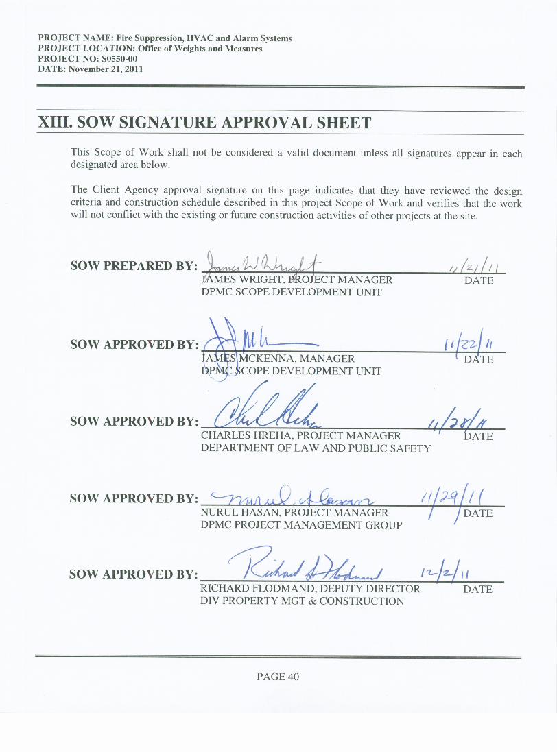
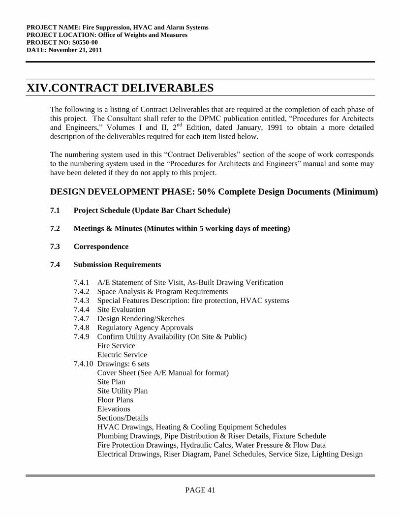
PROJECT NAME: Fire Suppression, HVAC and Alarm Systems
PROJECT LOCATION: Office of Weights and Measures
PROJECT NO: S0550-00
DATE: November 21, 2011
PAGE 41
XIV.CONTRACT DELIVERABLES
The following is a listing of Contract Deliverables that are required at the completion of each phase of
this project. The Consultant shall refer to the DPMC publication entitled, “Procedures for Architects
and Engineers,” Volumes I and II, 2nd
Edition, dated January, 1991 to obtain a more detailed
description of the deliverables required for each item listed below.
The numbering system used in this “Contract Deliverables” section of the scope of work corresponds
to the numbering system used in the “Procedures for Architects and Engineers” manual and some may
have been deleted if they do not apply to this project.
DESIGN DEVELOPMENT PHASE: 50% Complete Design Documents (Minimum)
7.1 Project Schedule (Update Bar Chart Schedule)
7.2 Meetings & Minutes (Minutes within 5 working days of meeting)
7.3 Correspondence
7.4 Submission Requirements
7.4.1 A/E Statement of Site Visit, As-Built Drawing Verification
7.4.2 Space Analysis & Program Requirements
7.4.3 Special Features Description: fire protection, HVAC systems
7.4.4 Site Evaluation
7.4.7 Design Rendering/Sketches
7.4.8 Regulatory Agency Approvals
7.4.9 Confirm Utility Availability (On Site & Public)
Fire Service
Electric Service
7.4.10 Drawings: 6 sets
Cover Sheet (See A/E Manual for format)
Site Plan
Site Utility Plan
Floor Plans
Elevations
Sections/Details
HVAC Drawings, Heating & Cooling Equipment Schedules
Plumbing Drawings, Pipe Distribution & Riser Details, Fixture Schedule
Fire Protection Drawings, Hydraulic Calcs, Water Pressure & Flow Data
Electrical Drawings, Riser Diagram, Panel Schedules, Service Size, Lighting Design
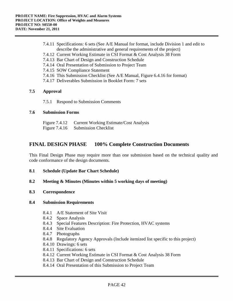
PROJECT NAME: Fire Suppression, HVAC and Alarm Systems
PROJECT LOCATION: Office of Weights and Measures
PROJECT NO: S0550-00
DATE: November 21, 2011
PAGE 42
7.4.11 Specifications: 6 sets (See A/E Manual for format, include Division 1 and edit to
describe the administrative and general requirements of the project)
7.4.12 Current Working Estimate in CSI Format & Cost Analysis 38 Form
7.4.13 Bar Chart of Design and Construction Schedule
7.4.14 Oral Presentation of Submission to Project Team
7.4.15 SOW Compliance Statement
7.4.16 This Submission Checklist (See A/E Manual, Figure 6.4.16 for format)
7.4.17 Deliverables Submission in Booklet Form: 7 sets
7.5 Approval
7.5.1 Respond to Submission Comments
7.6 Submission Forms
Figure 7.4.12 Current Working Estimate/Cost Analysis
Figure 7.4.16 Submission Checklist
FINAL DESIGN PHASE 100% Complete Construction Documents
This Final Design Phase may require more than one submission based on the technical quality and
code conformance of the design documents.
8.1 Schedule (Update Bar Chart Schedule)
8.2 Meeting & Minutes (Minutes within 5 working days of meeting)
8.3 Correspondence
8.4 Submission Requirements
8.4.1 A/E Statement of Site Visit
8.4.2 Space Analysis
8.4.3 Special Features Description: Fire Protection, HVAC systems
8.4.4 Site Evaluation
8.4.7 Photographs
8.4.8 Regulatory Agency Approvals (Include itemized list specific to this project)
8.4.10 Drawings: 6 sets
8.4.11 Specifications: 6 sets
8.4.12 Current Working Estimate in CSI Format & Cost Analysis 38 Form
8.4.13 Bar Chart of Design and Construction Schedule
8.4.14 Oral Presentation of this Submission to Project Team
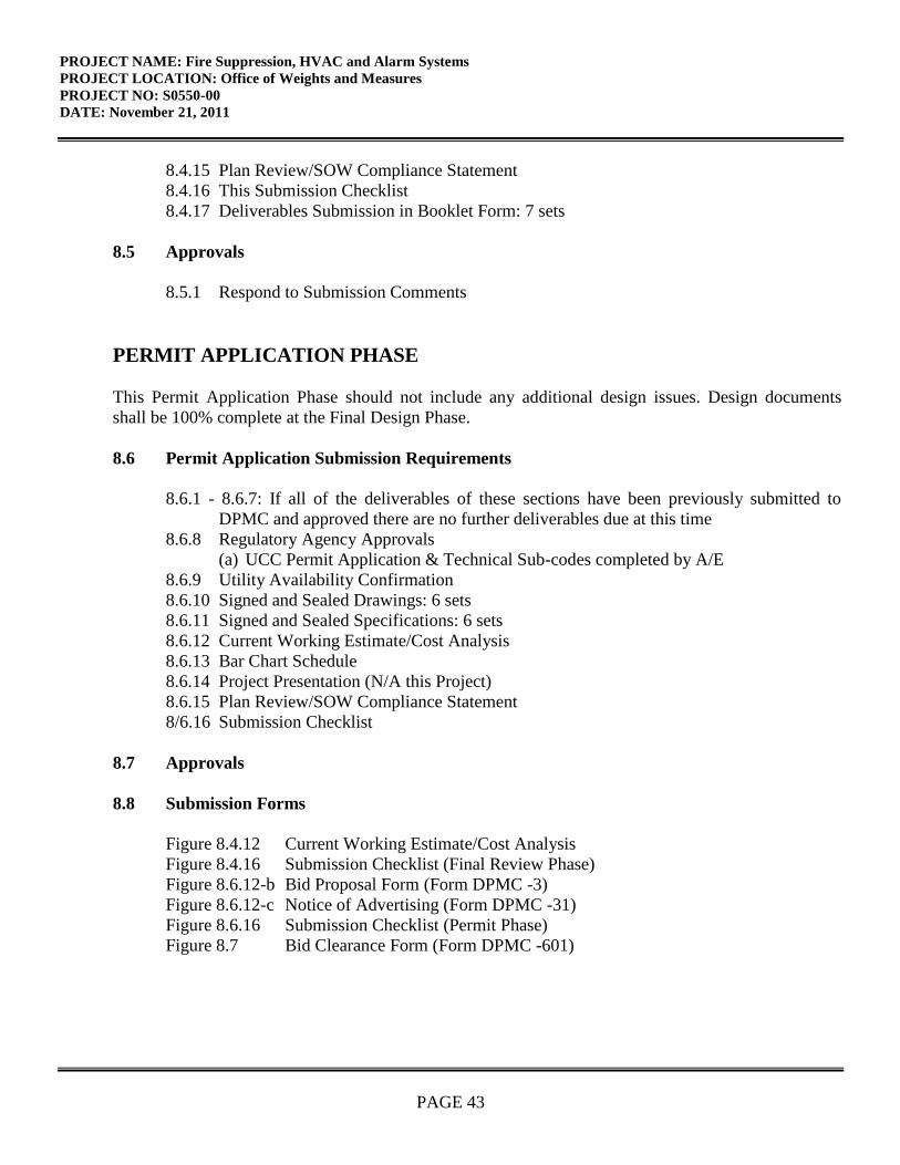
PROJECT NAME: Fire Suppression, HVAC and Alarm Systems
PROJECT LOCATION: Office of Weights and Measures
PROJECT NO: S0550-00
DATE: November 21, 2011
PAGE 43
8.4.15 Plan Review/SOW Compliance Statement
8.4.16 This Submission Checklist
8.4.17 Deliverables Submission in Booklet Form: 7 sets
8.5 Approvals
8.5.1 Respond to Submission Comments
PERMIT APPLICATION PHASE
This Permit Application Phase should not include any additional design issues. Design documents
shall be 100% complete at the Final Design Phase.
8.6 Permit Application Submission Requirements
8.6.1 - 8.6.7: If all of the deliverables of these sections have been previously submitted to
DPMC and approved there are no further deliverables due at this time
8.6.8 Regulatory Agency Approvals
(a) UCC Permit Application & Technical Sub-codes completed by A/E
8.6.9 Utility Availability Confirmation
8.6.10 Signed and Sealed Drawings: 6 sets
8.6.11 Signed and Sealed Specifications: 6 sets
8.6.12 Current Working Estimate/Cost Analysis
8.6.13 Bar Chart Schedule
8.6.14 Project Presentation (N/A this Project)
8.6.15 Plan Review/SOW Compliance Statement
8/6.16 Submission Checklist
8.7 Approvals
8.8 Submission Forms
Figure 8.4.12 Current Working Estimate/Cost Analysis
Figure 8.4.16 Submission Checklist (Final Review Phase)
Figure 8.6.12-b Bid Proposal Form (Form DPMC -3)
Figure 8.6.12-c Notice of Advertising (Form DPMC -31)
Figure 8.6.16 Submission Checklist (Permit Phase)
Figure 8.7 Bid Clearance Form (Form DPMC -601)
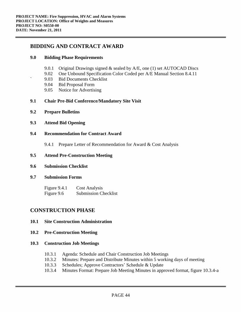
PROJECT NAME: Fire Suppression, HVAC and Alarm Systems
PROJECT LOCATION: Office of Weights and Measures
PROJECT NO: S0550-00
DATE: November 21, 2011
PAGE 44
BIDDING AND CONTRACT AWARD
9.0 Bidding Phase Requirements
9.0.1 Original Drawings signed & sealed by A/E, one (1) set AUTOCAD Discs
9.02 One Unbound Specification Color Coded per A/E Manual Section 8.4.11
` 9.03 Bid Documents Checklist
9.04 Bid Proposal Form
9.05 Notice for Advertising
9.1 Chair Pre-Bid Conference/Mandatory Site Visit
9.2 Prepare Bulletins
9.3 Attend Bid Opening
9.4 Recommendation for Contract Award
9.4.1 Prepare Letter of Recommendation for Award & Cost Analysis
9.5 Attend Pre-Construction Meeting
9.6 Submission Checklist
9.7 Submission Forms
Figure 9.4.1 Cost Analysis
Figure 9.6 Submission Checklist
CONSTRUCTION PHASE
10.1 Site Construction Administration
10.2 Pre-Construction Meeting
10.3 Construction Job Meetings
10.3.1 Agenda: Schedule and Chair Construction Job Meetings
10.3.2 Minutes: Prepare and Distribute Minutes within 5 working days of meeting
10.3.3 Schedules; Approve Contractors’ Schedule & Update
10.3.4 Minutes Format: Prepare Job Meeting Minutes in approved format, figure 10.3.4-a
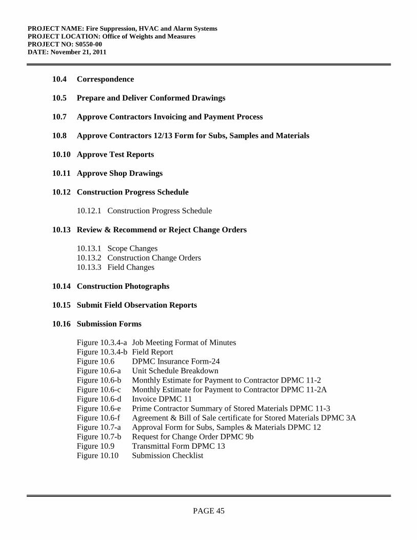
PROJECT NAME: Fire Suppression, HVAC and Alarm Systems
PROJECT LOCATION: Office of Weights and Measures
PROJECT NO: S0550-00
DATE: November 21, 2011
PAGE 45
10.4 Correspondence
10.5 Prepare and Deliver Conformed Drawings
10.7 Approve Contractors Invoicing and Payment Process
10.8 Approve Contractors 12/13 Form for Subs, Samples and Materials
10.10 Approve Test Reports
10.11 Approve Shop Drawings
10.12 Construction Progress Schedule
10.12.1 Construction Progress Schedule
10.13 Review & Recommend or Reject Change Orders
10.13.1 Scope Changes
10.13.2 Construction Change Orders
10.13.3 Field Changes
10.14 Construction Photographs
10.15 Submit Field Observation Reports
10.16 Submission Forms
Figure 10.3.4-a Job Meeting Format of Minutes
Figure 10.3.4-b Field Report
Figure 10.6 DPMC Insurance Form-24
Figure 10.6-a Unit Schedule Breakdown
Figure 10.6-b Monthly Estimate for Payment to Contractor DPMC 11-2
Figure 10.6-c Monthly Estimate for Payment to Contractor DPMC 11-2A
Figure 10.6-d Invoice DPMC 11
Figure 10.6-e Prime Contractor Summary of Stored Materials DPMC 11-3
Figure 10.6-f Agreement & Bill of Sale certificate for Stored Materials DPMC 3A
Figure 10.7-a Approval Form for Subs, Samples & Materials DPMC 12
Figure 10.7-b Request for Change Order DPMC 9b
Figure 10.9 Transmittal Form DPMC 13
Figure 10.10 Submission Checklist
PROJECT NAME: Fire Suppression, HVAC and Alarm Systems
PROJECT LOCATION: Office of Weights and Measures
PROJECT NO: S0550-00
DATE: November 21, 2011
PAGE 46
PROJECT CLOSE-OUT PHASE
11.1 Responsibilities: Plan, Schedule and Execute Close-Out Activities
11.2 Commencement: Initiate Close-Out w/DPMC 20A Project Close-Out Form
11.3 Develop Punch List & Inspection Reports
11.4 Verify Correction of Punch List Items
11.5 Determination of Substantial Completion
11.6 Ensure Issuance of “Temporary Certificate of Occupancy or Approval”
11.7 Initiation of Final Contract Acceptance Process
11.8 Submission of Close-Out Documentation
11.8.1 As-Built & Record Set Drawings, 3 sets AUTOCAD Discs Delivered to DPMC
11.8.2 (a) Maintenance and Operating manuals, Warranties, etc.: 7 sets each
(b) Guarantees
(c) Testing and Balancing Reports
(d) Shop Drawings
(e) Letter of Contract Performance
11.8.3 Final Cost Analysis-Insurance Transfer DPMC 25
11.8.4 This Submission Checklist
11.9 Final Payment
11.9.1 Contractors Final Payment
11.9.2 A/E Invoice and Close-Out Forms for Final Payment
11.10 Final Performance Evaluation of the A/E and the Contractors
11.11 Ensure Issuance of a “Certificate of Occupancy or Approval”
11.12 Submission Forms
Figure 11.2 Project Close-Out Documentation List DPMC 20A
Figure 11.3-a Certificate of Substantial Completion DPMC 20D
Figure 11.3-b Final Acceptance of Consultant Contract DPMC 20C
Figure 11.5 Request for Contract Transition Close-Out DPMC 20X
Figure 11.7 Final Contract Acceptance Form DPMC 20
PROJECT NAME: Fire Suppression, HVAC and Alarm Systems
PROJECT LOCATION: Office of Weights and Measures
PROJECT NO: S0550-00
DATE: November 21, 2011
PAGE 47
Figure 11.8.3-a Final Cost Analysis
Figure 11.8.3-b Insurance Transfer Form DPMC 25
Figure 11.8.4 Submission Checklist
XV. EXHIBITS
The attached exhibits in this section will include a sample project schedule, and any supporting
documentation to assist the Consultant in the design of the project such as maps, drawings,
photographs, floor plans, studies, reports, etc.
END OF SCOPE OF WORK
February 7, 1997Rev.: January 29, 2002
Responsible Group Code Table
The codes below are used in the schedule field “GRP” that identifies the group responsible for theactivity. The table consists of groups in the Division of Property Management & Construction(DPMC), as well as groups outside of the DPMC that have responsibility for specific activities ona project that could delay the project if not completed in the time specified. For reportingpurposes, the groups within the DPMC have been defined to the supervisory level ofmanagement (i.e., third level of management, the level below the Associate Director) to identifythe “functional group” responsible for the activity.
CODE DESCRIPTION REPORTS TO ASSOCIATE DIRECTOR OF:
CM Contract Management Group Contract Management
CA Client Agency N/A
CSP Consultant Selection and Technical ServicesPrequalification Group
AlE Architect/Engineer N/A
PR Plan Review Group Technical Services
CP Construction Procurement Planning & Administration
CON Construction Contractor N/A
FM Financial Management Group Planning & Administration
OEU Office of Energy and N/AUtility Management
PD Project Development Group Planning & Administration
EXHIBIT ‘A’
Act
ivity
lW
kID
Des
crip
tion
j9
mn
11
rnH
i..
.flH
Iiii
iI3H
Hii3
I
II
I
II
I
IL
’!
IC
V3t
Sche
dule
/Con
duct
Pred
esig
n/Pr
ojec
t Kic
kO
ffM
tgC
MI
II
.II;’
l:IiII_I:
IC
V30
50Pr
epar
ePro
gram
Phas
eSu
bmitt
alP
iECV
302l
Dis
trib
ute
Prog
ram
Subm
ittal
for R
evie
wC
MI
—.1
H.
•.
H:.L
’.11
HCV
3O7
Pre
pare
&S
ub
mit
Pre
ct
Cost
Anal
ysi
s(D
PM
C38)
CM
ICV
3022
Rev
iew
&A
ppro
ve
Prog
ram
Subm
itta
lC
A
L1
CV30
23R
evie
w&
App
rove
Prog
ram
Subm
itta
lP
RI1
1—
—CY
3024
Rev
iew
&A
ppro
ve
Pro
gra
mS
ubm
itta
lC
MI
1CV
3025
Con
soli
date
&R
eturn
Prog
ram
Subm
itta
lC
omm
ents
CM
IV
CV3V
IOP
repa
reSc
hem
atic
Pha
seS
ubm
itta
lPi
EI
I—
IIi
i‘I
CV30
3iD
istr
ibute
Sche
mat
icSu
bmitt
alfo
rR
evie
wC
MI
I——
--
—-
-
——
—-
——
-L
——
-—
CVSQ
S7Pr
epar
e&
Subm
itP
roje
ctC
ost A
nal
ysi
s(D
PMC
38)
CM
I
III
II
iII
I:13131
IuII’H
HCV
3OSZ
Rev
iew
&A
ppro
veS
chem
atic
Subin
itts
lC
AH
iH
’H
’‘‘
‘H
•‘
Hi
‘CV
3033
Rev
iew
&A
ppro
ve
Sch
emat
icS
ubm
itta
lP
RI
:CV
3034
Rev
iew
&A
ppro
ve
Sche
mat
icSu
bmitt
alC
M1
V4I_3
.IV
,,V
I,,V
VV
3O
Con
soli
date
&R
etur
nScl
icm
atic
Sub
mit
talo
mm
ent
CM
:ilII3,,..4
.1
43•
II
11111
43
IIV
,’Il
1.11:
II
43
3.1151.
44
‘till
3H
1411,,l_.i
‘‘H
——
—
1”
I‘
‘I
——
—“
‘
CVSO
4OP
iepa
reD
esig
nD
evel
opm
ent
Pha
seS
ubnu
ltal
AE
.I
4.
V3
Vj
—II
III
111’
4:
II.
•:
4.1
II
I.1.
31
III3.
I3
;1
Ii
CV
3O1
Dis
trib
uteD
DSu
bmitt
alfo
r Rev
iew
CM
3(V
iO47
Pre
par
e&
Su
bm
itP
roje
ctC
ost
Ana
lysi
s(D
PM
C3
8)
CM
31
33
CV30
42R
evie
w&
Appro
ve
Des
ign
Dev
elopm
ent
Su
bm
itta
lC
A1
11
3
3C
’30
3R
evie
w&
Appro
ve
Des
ign
Dev
elopm
ent
Su
bm
itta
lP
RI
CV
3044
Rev
iew
&A
ppro
ve
Des
ign
Dev
elopm
ent
Sub
mit
tal
CM
1
3
3
3CV
SO4S
Con
soli
date
&R
etur
nI)
DS
ubm
itta
lC
om
men
tsC
MI
33
CV3O
SOP
rep
are
Fin
alD
esig
nP
hase
Subm
itta
lI
33
31
CV
3OSI
Dis
trib
ute
Fina
lDesig
nSu
bmitt
alfo
r Rev
iew
CM
I3
IC
’b’
Rev
iew
&Ap
prov
eF
inal
Des
ign
Subm
ittal
CA
43
Rev
iew
&A
ppro
ve
Fin
alD
esig
nS
ubm
itta
lP
RI
CV
3054
Rev
iew
Fin
alD
esig
nS
ubm
itl
forC
onst
ruct
abil
ity
OC
S—
NO
TE
:.
DT
Tsh
eet t
or3
——
Ref
erto
sect
ion
“IV
Pro
ject
Sch
edul
e”of
the
Bur
eau
ofD
esig
n&
Con
stru
ctio
nS
ervi
ces
Scop
eof
Wor
kfo
rco
ntra
ctph
ase
dura
tions
.R
outi
neP
roje
ctE
xli
i bit
0P
rtm
avor
aS
yste
ms,
Inc.
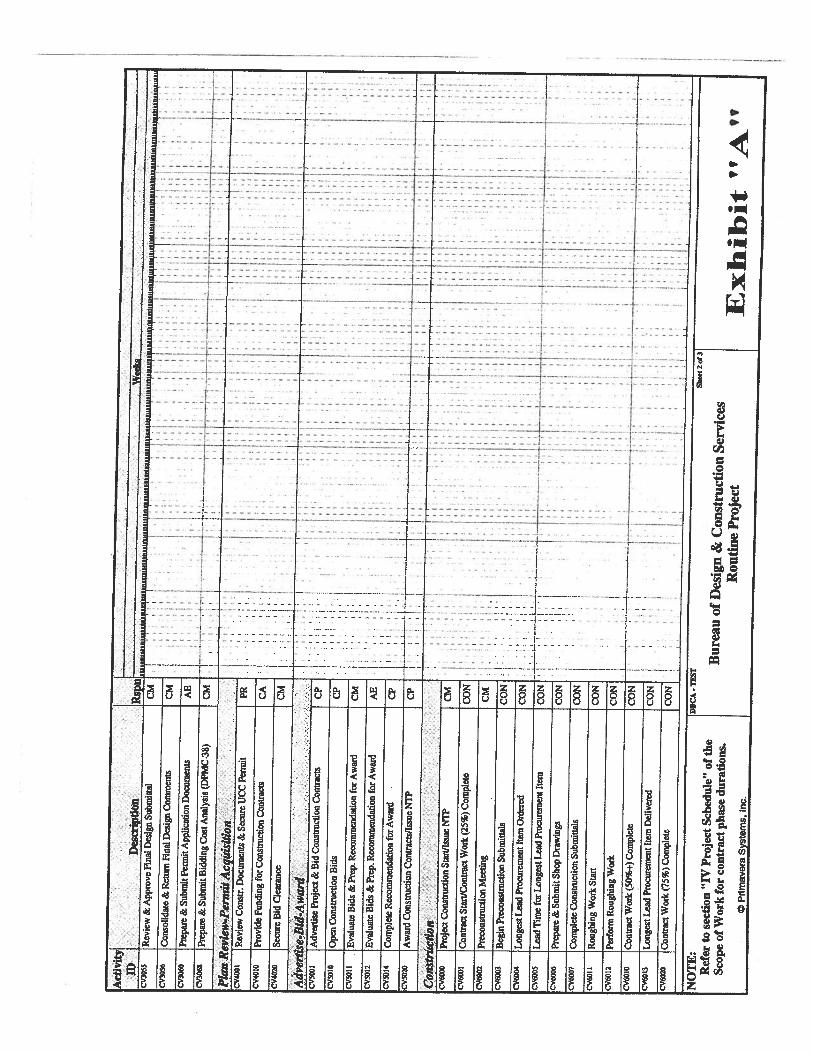
-U
3
q)
03
o-
C0
,0CC
p.
CC
—s
--
{-
L--I-
---——--L---—
:::1:::1::.::::.:.::z:::::.::::L—
9 .........
F.;-.+.
1----1-------
L .i...4...
.—...4.1..-
I-----I----
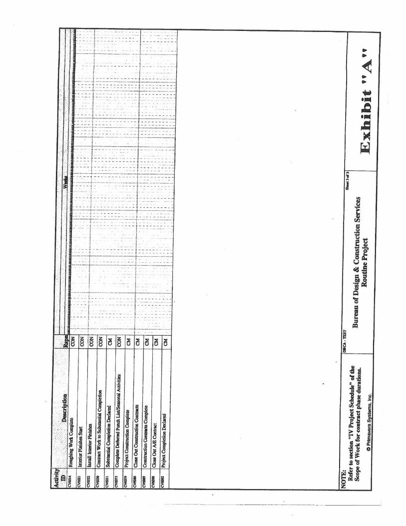
I
0
3
C’,‘9
30,
I00
I I
0
000On00zz.
0,
?.1
—---.-.--r--—
-.:
.-
--.-.t.——-----
-.
-ZEt---
::z:.
•.t.:
-.)-----
.3.—.--——--
-1”-----
:-•-----.
:_:.L:_-
::_f----
-—
--•--..-
—H----——----
-1---------
--——-
-—.t-—-. —-
.I--
i.--.——-—-.-——— .—
-—------------.——.--------------
—-—.-.-—
-I-—----
-f-----b-.- -—-———.—--—————.—————
—I
.4
-.
-:-T-:.-
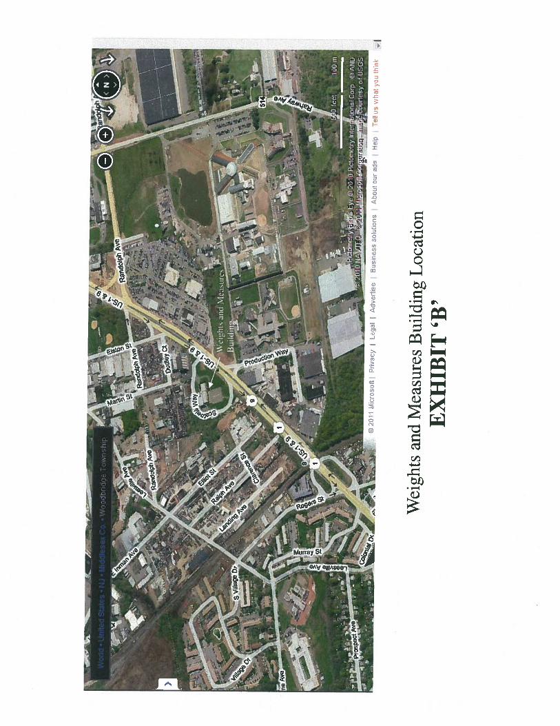
r—
- r&.
__A
4%:
______
Ia
Wei
ghts
and
Mea
sure
s
4\c
AJ
XX
aJS
Pts
__
4I3A
:fP
at
__--a
_
)2C
iP
rrac
yL
egal
Adv
erti
se.
s.
Wei
ghts
and
Mea
sure
sB
uild
ing
Loc
atio
nE
XH
IBIT
‘B’
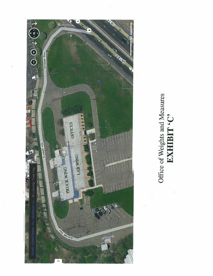
Off
ice
ofW
eigh
tsan
dM
easu
res
EX
HIB
IT‘C
’
ITR
icK
W°
-.-
‘O
fFIC
ES
LM
3’m
Presented to:The State of New Jersey
Department of Law and Public SafetyOffice of the Attorney General
for the:
Weights and Measures BuildingFire Alarm and Fire ProtectionSystems Study1261 Route 1&9 South, Avenel, NJ 07001
In i?e/erence to:Project Number X0150-00, Work Order 2
March 30, 2011
Suhmiited th;:
Jacobs Architects/Engineers. Inc.299 Madison AvenueMorristown, NJ 07962(973) 267-0555
EXHIBIT ‘D’
JACOBS
Weights and Measures Building March 30, 2011Avenel, NJFire Alarm and Fire Protection Systems Study
TABLE OF CONTENTS
Section Page
1.0 Introduction 12.0 Existing Systems and Conditions 23.0 System Deficiencies 74.0 Recommendations 85.0 Opinion of Probable Cost 106.0 Summary 11
AppendixOpinion of Probable Construction Cost Detail A-IPhotos B-IExisting Fire Alarm System Components
JACOBS
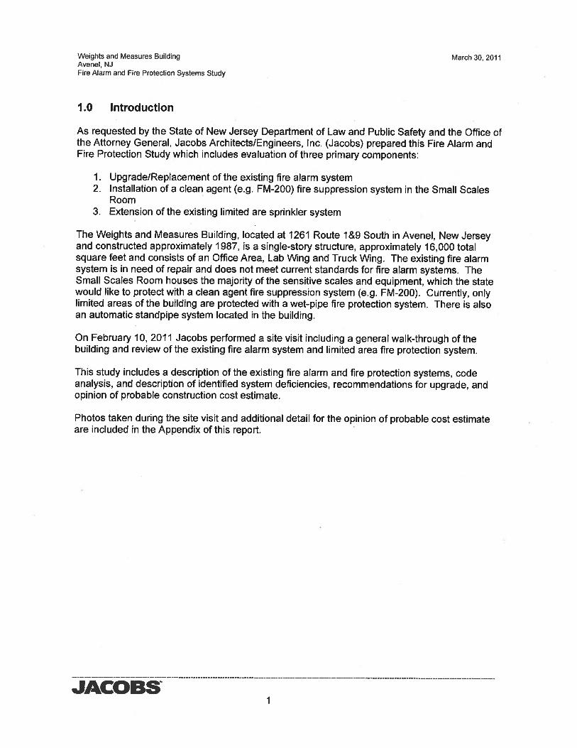
Weights and Measures Building March 30, 2011Avenel, NJFire Alarm and Fire Protection Systems Study
1.0 Introduction
As requested by the State of New Jersey Department of Law and Public Safety and the Office ofthe Attorney General, Jacobs Architects/Engineers, Inc. (Jacobs) prepared this Fire Alarm andFire Protection Study which includes evaluation of three primary components:
1. Upgrade/Replacement of the existing fire alarm system2. Installation of a clean agent (e.g. FM-200) fire suppression system in the Small Scales
Room3. Extension of the existing limited are sprinkler system
The Weights and Measures Building, located at 1261 Route l&9 South in Avenel, New Jerseyand constructed approximately 1987, is a single-story structure, approximately 16,000 totalsquare feet and consists of an Office Area, Lab Wing and Truck Wing. The existing fire alarmsystem is in need of repair and does not meet current standards for fire alarm systems. TheSmall Scales Room houses the majority of the sensitive scales and equipment, which the statewould like to protect with a clean agent fire suppression system (e.g. FM-200). Currently, onlylimited areas of the building are protected with a wet-pipe fire protection system. There is alsoan automatic standpipe system located in the building.
On February 10, 2011 Jacobs performed a site visit including a general walk-through of thebuilding and review of the existing fire alarm system and limited area fire protection system.
This study includes a description of the existing fire alarm and fire protection systems, codeanalysis, and description of identified system deficiencies, recommendations for upgrade, andopinion of probable construction cost estimate.
Photos taken during the site visit and additional detail for the opinion of probable cost estimateare included in the Appendix of this report.
JACOBS1
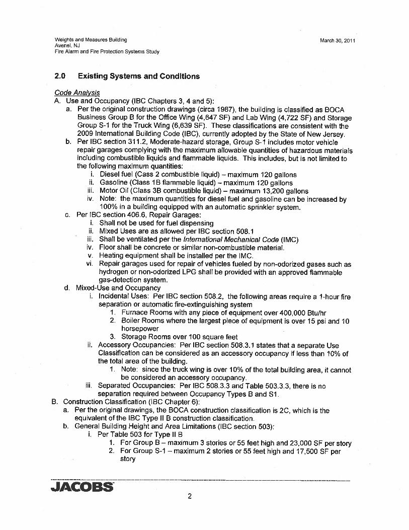
Weights and Measures Building March 30, 2011Avenel, NJFire Alarm and Fire Protection Systems Study
2.0 Existing Systems and Conditions
Code AnalysisA. Use and Occupancy (IBC Chapters 3, 4 and 5):
a. Per the original construction drawings (circa 1987), the building is classified as BOCABusiness Group B for the Office Wing (4,647 SF) and Lab Wng (4,722 SF) and StorageGroup S-i for the Truck Wing (6,639 SF). These classifications are consistent with the2009 International Building Code (IBC), currently adopted by the State of New Jersey.
b. Per IBC section 311.2, Moderate-hazard storage, Group S-I includes motor vehiclerepair garages complying with the maximum allowable quantities of hazardous materialsincluding combustible liquids and flammable liquids. This includes, but is not limited tothe following maximum quantities:
i. Diesel fuel (Cass 2 combustible liquid) — maximum 120 gallonsii. Gasoline (Class lB flammable liquid) — maximum 120 gallons
iii. Motor Oil (Class 3B combustible liquid) — maximum 13,200 gallonsiv. Note: the maximum quantities for diesel fuel and gasoline can be increased by
100% in a building equipped with an automatic sprinkler system.c. Per IBC section 406.6, Repair Garages:
i. Shall not be used for fuel dispensingii. Mixed Uses are as allowed per IBC section 508.1
iii. Shall be ventilated per the International Mechanical Code (IMC)iv. Floor shall be concrete or similar non-combustible material.v. Heating equipment shall be installed per the IMC.
vi. Repair garages used for repair of vehicles fueled by non-odorized gases such ashydrogen or non-odorized LPG shall be provided with an approved flammablegas-detection system.
d. Mixed-Use and Occupancyi. Incidental Uses: Per IBC section 508.2, the following areas require a 1-hour fire
separation or automatic fire-extinguishing system1. Furnace Rooms with any piece of equipment over 400,000 Btu/hr2. Boiler Rooms where the largest piece of equipment is over 15 psi and 10
horsepower3. Storage Rooms over 100 square feet
ii. Accessory Occupancies: Per IBC section 508.3.1 states that a separate UseClassification can be considered as an accessory occupancy if less than 10% ofthe total area of the building.
1. Note: since the truck wing is over 10% of the total building area, it cannotbe considered an accessory occupancy.
iii. Separated Occupancies: Per IBC 508.3.3 and Table 503.3.3, there is noseparation required between Occupancy Types B and SI.
B. Construction Classification (IBC Chapter 6):a. Per the original drawings, the BOCA construction classification is 2C, which is the
equivalent of the IBC Type II B construction classification.b. General Building Height and Area Limitations (IBC section 503):
i. Per Table 503 for Type II BI. For Group B — maximum 3 stories or 55 feet high and 23,000 SF per story2. For Group S-i — maximum 2 stories or 55 feet high and 17,500 SF per
story
JACOBS2
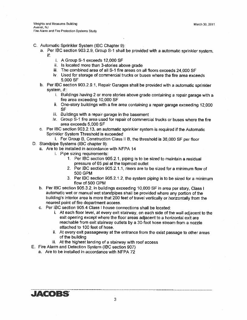
Weights and Measures Building March 30, 2011Avenel. NJFire Alarm and Fire Protection Systems Study
C. Automatic Sprinkler System (IBC Chapter 9):a. Per IBC section 903.2.9, Group S-i shall be provided with a automatic sprinkler system,
if:i. A Group 5-1 exceeds 12,000 SF
ii. Is located more than 3-stories above gradeiii. The combined area of all S-I fire areas on all floors exceeds 24,000 SFiv. Used for storage of commercial trucks or buses where the fire area exceeds
5,000 SFb. Per IBC section 903.2.9.1, Repair Garages shall be provided with a automatic sprinkler
system, if::i. Buildings having 2 or more stories above grade containing a repair garage with a
fire area exceeding 10,000 SFii. One-story buildings with a fire area containing a repair garage exceeding 12,000
SFiii. Buildings with a repair garage in the basementiv. Group 5-1 fire area used for repair of commercial trucks or buses where the fire
area exceeds 5,000 SFc. Per IBC section 903.2.13, an automatic sprinkler system is required if the Automatic
Sprinkler System Threshold is exceededi. For Group B, Construction Class II B, the threshold is 36,000 SF per floor
D. Standpipe Systems (IBC chapter 9):a. Are to be installed in accordance with NFPA 14
i. Pipe sizing requirements:I. Per IBC section 905.2.1, piping is to be sized to maintain a residual
pressure of 65 psi at the topmost outlet2. Per IBC section 905.2.1.1, risers are to be sized for a minimum flow of
500 GPM3. Per IBC section 905.2.1.2, the system piping is to be sized for a minimum
flow of 500 GPMb. Per IBC section 905.3.2, in buildings exceeding 10,000 SF in area per story, Class I
automatic wet or manual wet standpipes shall be provided where any portion of thebuilding’s interior area is more that 200 feet of travel vertically or horizontally from thenearest point of fire department access.
c. Per IBC section 905.4 Class I house connections shall be located:i. At each floor level, at every exit stairway, on each side of the wall adjacent to the
exit opening except where the floor areas adjacent to a horizontal exit arereachable from exit stairway outlets by a 30-foot hose stream from a nozzleattached to 100 feet of hose.
ii. At every exit passageway at the entrance from the exist passage to other areasof the building
iii. At the highest landing of a stairway with roof accessE. Fire Alarm and Detection System (IBC section 907)
a. Are to be installed in accordance with NFPA 72
JACOBS3
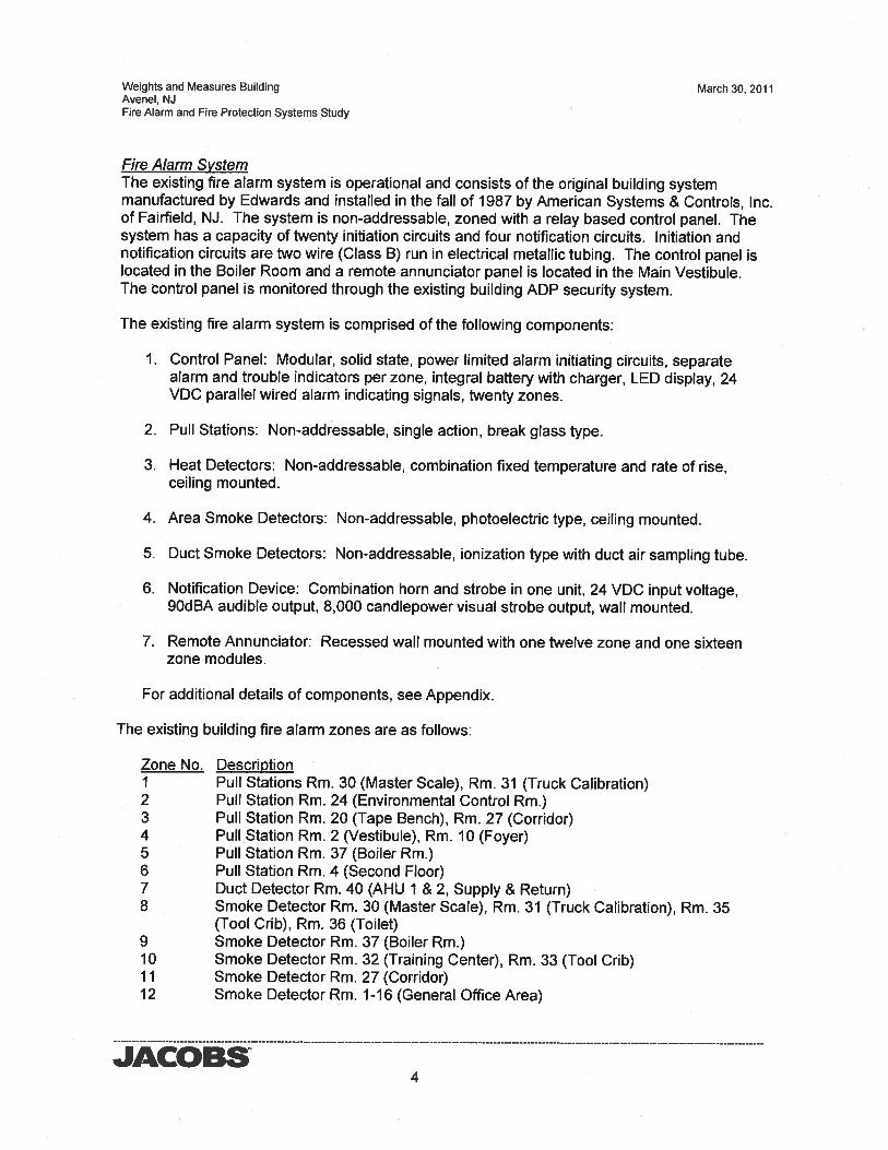
Weights and Measures Building March 30, 2011Avenel. NJFire Alarm and Fire Protection Systems Study
Fire Alarm SystemThe existing fire alarm system is operational and consists of the original building systemmanufactured by Edwards and installed in the fall of 1987 by American Systems & Controls, Inc.of Fairfield, NJ. The system is non-addressable, zoned with a relay based control panel. Thesystem has a capacity of twenty initiation circuits and four notification circuits. Initiation andnotification circuits are two wire (Class B) run in electrical metallic tubing. The control panel islocated in the Boiler Room and a remote annunciator panel is located in the Main Vestibule.The control panel is monitored through the existing building ADP security system.
The existing fire alarm system is comprised of the following components:
1. Control Panel: Modular, solid state, power limited alarm initiating circuits, separatealarm and trouble indicators per zone, integral battery with charger, LED display, 24VDC parallel wired alarm indicating signals, twenty zones.
2. Pull Stations: Non-addressable, single action, break glass type.
3. Heat Detectors: Non-addressable, combination fixed temperature and rate of rise,ceiling mounted.
4. Area Smoke Detectors: Non-addressable, photoelectric type, ceiling mounted.
5. Duct Smoke Detectors: Non-addressable, ionization type with duct air sampling tube.
6. Notification Device: Combination horn and strobe in one unit, 24 VDC input voltage,9OdBA audible output, 8,000 candlepower visual strobe output, wall mounted.
7. Remote Annunciator: Recessed wall mounted with one twelve zone and one sixteenzone modules.
For additional details of components, see Appendix.
The existing building fire alarm zones are as follows:
Zone No. DescriptionI Pull Stations Rm. 30 (Master Scale), Rm. 31 (Truck Calibration)2 Pull Station Rm. 24 (Environmental Control Rm.)3 Pull Station Rm. 20 (Tape Bench), Rm. 27 (Corridor)4 Pull Station Rm. 2 (Vestibule), Rm. 10 (Foyer)5 Pull Station Rm. 37 (Boiler Rm.)6 Pull Station Rm. 4 (Second Floor)7 Duct Detector Rm. 40 (AHU I & 2, Supply & Return)8 Smoke Detector Rm. 30 (Master Scale), Rm. 31 (Truck Calibration), Rm. 35
(Tool Crib), Rm. 36 (Toilet)9 Smoke Detector Rm. 37 (Boiler Rm.)10 Smoke Detector Rm. 32 (Training Center), Rm. 33 (Tool Crib)11 Smoke Detector Rm. 27 (Corridor)12 Smoke Detector Rm. 1-16 (General Office Area)
JACOBS4
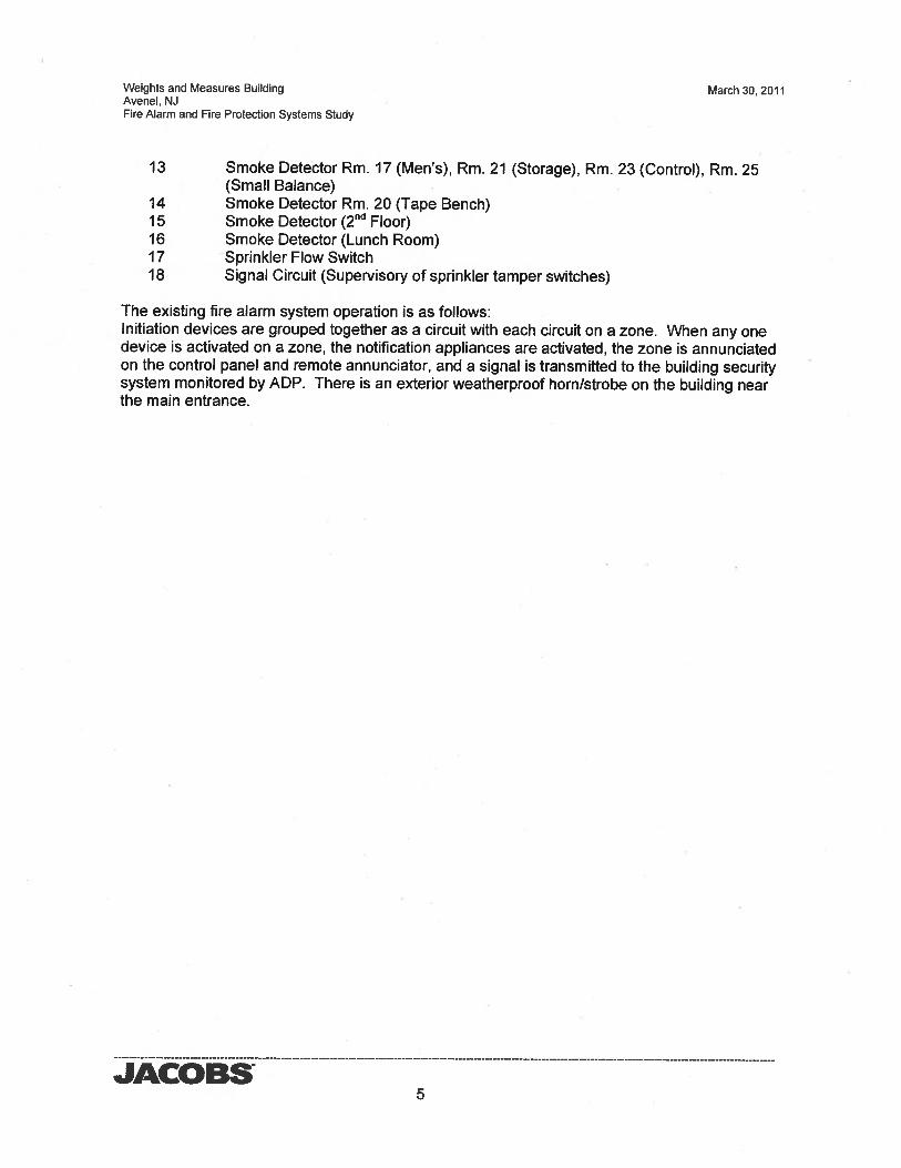
Weights and Measures Building March 30, 2011Avenel, NJFire Alarm and Fire Protection Systems Study
13 Smoke Detector Rm. 17 (Men’s), Rm. 21 (Storage), Rm. 23 (Control), Rm. 25(Small Balance)
14 Smoke Detector Rm. 20 (Tape Bench)15 Smoke Detector (2 Floor)16 Smoke Detector (Lunch Room)17 Sprinkler Flow Switch18 Signal Circuit (Supervisory of sprinkler tamper switches)
The existing fire alarm system operation is as follows:Initiation devices are grouped together as a circuit with each circuit on a zone. When any onedevice is activated on a zone, the notification appliances are activated, the zone is annunciatedon the control panel and remote annunciator, and a signal is transmitted to the building securitysystem monitored by ADP. There is an exterior weatherproof horn/strobe on the building nearthe main entrance.
JACOBS5
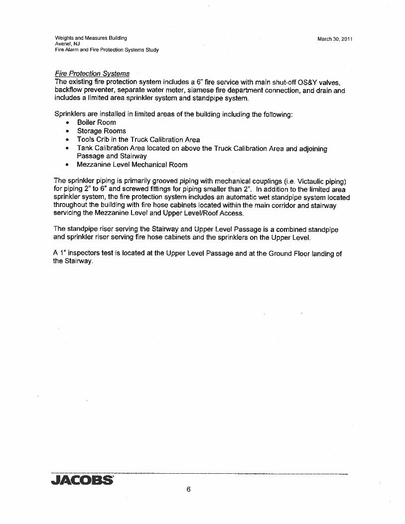
Weights and Measures Building March 30, 2011Avenel, NJFire Alarm and Fire Protection Systems Study
Fire Protection SystemsThe existing fire protection system includes a 6” fire service with main shut-off OS&Y valves,backflow preventer, separate water meter, siamese fire department connection, and drain andincludes a limited area sprinkler system and standpipe system.
Sprinklers are installed in limited areas of the building including the following:• Boiler Room• Storage Rooms• Tools Crib in the Truck Calibration Area• Tank Calibration Area located on above the Truck Calibration Area and adjoining
Passage and Stairway• Mezzanine Level Mechanical Room
The sprinkler piping is primarily grooved piping with mechanical couplings (i.e. Victaulic piping)for piping 2” to 6” and screwed fittings for piping smaller than 2”. In addition to the limited areasprinkler system, the fire protection system includes an automatic wet standpipe system locatedthroughout the building with fire hose cabinets located within the main corridor and stairwayservicing the Mezzanine Level and Upper Level/Roof Access.
The standpipe riser serving the Stairway and Upper Level Passage is a combined standpipeand sprinkler riser serving fire hose cabinets and the sprinklers on the Upper Level.
A 1” inspectors test is located at the Upper Level Passage and at the Ground Floor landing ofthe Stairway.
JACOBS6
Weights and Measures Building March 30, 2011Avenel, NJFire Alarm and Fire Protection Systems Study
3.0 System Deficiencies
Fire Alarm System1. The existing fire alarm is an antiquated, non-addressable system with obsolete parts.
Modern systems are addressable and more energy efficient.2. Some of the notification appliances do not operate at their full output. Also from casual
observation it appears the visual notification may not meet current code (NFPA 72)requirements.
Fire Protection SystemsI. In general, the existing limited area sprinkler and standpipe systems comply with current
code requirements. However, the 2009 update of the BC includes added criteria that wouldrequire an automatic sprinkler system in a Group S-I fire area used for repair of commercialtrucks or buses where the fire area exceeds 5,000 SF. There are currently no sprinklers inthe truck wing, except for the tools crib area and at the tank calibration area located above.
2. It is our understanding that per previous risk analysis performed for insurance purposes, itwas recommended that the Small Balance Room be provided with a clean agent firesuppression system (e.g. FM200 fire suppression system).
JACOBS7
Weights and Measures Building March 30, 2011Avenel, NJFire Alarm and Fire Protection Systems Study
4.0 Recommendations
Fire Alarm SystemGiven the age of the system and the unavailability of replacement parts, a completely new firealarm and detection system should be installed throughout the building. The new systemshould be a microprocessor-based addressable coded notification signal and detection systemwith automatic alarm communication to the existing ADP security system.
Modern fire alarm systems have the initiation devices on one circuit with each device having itsown address (zone). When a device is activated, the individual device is annunciated at thecontrol panel and remote annunciator and the alarm is activated. The existing fire alarm systemhas eighteen circuits with an end of the line resistor at the end of each circuit. The existing firealarm wiring can not be reused for the new system because the addressable system onlyrequires one circuit with one end of the line resistor. Additionally, the existing appliancenotification circuits have suspect reliability and should not be reused. The manufacturerfinstallerof the new system may not warrantee the existing wiring, even with extensive testing andinvestigating the exact wiring runs.
The new fire alarm detectors will be equivalent to the existing types with addition of beingaddressable. The new pull stations will be addressable and double action type without thebreak glass rod. The new horn/strobes will be addressable with adjustable output.
The new fire alarm wiring will be Class B, two wire with exposed cabling above accessibleceilings, in surface mounted electric metallic tubing (EMT) in unfinished areas and in surfacemetal raceways in exposed finished areas. Surface mounted EMT and surface metal racewaywill be painted to match the existing finishes of the area where installed.
The existing fire alarm system will remain in service until the new system is operational. Afteracceptance of the new system, the existing system components, wiring and exposed racewayswill be removed and disturbed surfaces patched and painted.
Fire Protection Systems1. Install a clean agent system for the Small Balance Room as this room includes expensive
and sensitive equipment and was previously recommended for insurance purposes. Thiswould generally include the following:
a. FM-200 tanksb. Control panelc. Bell, horn Strobe, and discharge strobed. Nozzles and pipinge. Signage
Delivery of an FM-200 system is typically provided as a “Turn-key” system includingengineering, professional engineer sealed drawings, permits, functional testing, certification,union installation and room integrity fan test in accordance with NFPA 2001.
Note: The room will require certain upgrades to seal the room in order for it to pass the fantest. This may include replacement of the existing drop ceiling with a gypsum board ceilingand replacement of the door with a tight-fitting or gasketed door.
JACOBS8
Weights and Measures Building March 30, 2011Avenel, NJFire Alarm and Fire Protection Systems Study
2. Although not required since the facility was constructed under a previous edition of theBuilding Code and NJ adopted subcodes, sprinklers could be added to the truck wing inorder to bring that portion of the building into compliance with the current coderequirements. It should be noted that this could have an impact on the currently installedsystem and devices and may require other modifications to the existing system so that theentire system meets the latest code requirements. This would include new flowrequirements, fire hydrant testing, etc. Additionally, the current water service is a combineddomestic and fire service, It is usually preferred by the authority having jurisdiction to havea separate and dedicated service for the fire suppression systems.
JACOBS9
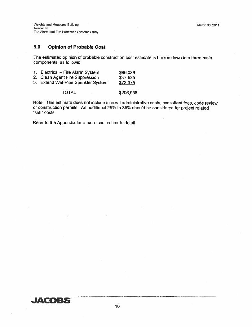
Weights and Measures Building March 30, 2011Avenel, NJFire Alarm and Fire Protection Systems Study
5.0 Opinion of Probable Cost
The estimated opinion of probable construction cost estimate is broken down into three maincomponents, as follows:
1. Electrical — Fire Alarm System $86,0362. Clean Agent Fire Suppression $47,5253. Extend Wet-Pipe Sprinkler System $73375
TOTAL $206,938
Note: This estimate does not include internal administrative costs, consultant fees, code review,or construction permits. An additional 25% to 35% should be considered for project related“soft” costs.
Refer to the Appendix for a more cost estimate detail.
JACOBS10
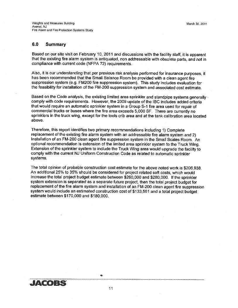
Weights and Measures Building March 30, 2011Avenel, NJFire Alarm and Fire Protection Systems Study
6.0 Summary
Based on our site visit on February 10, 2011 and discussions with the facility staff, it is apparentthat the existing fire alarm system is antiquated, non addressable with obsolete parts, and not incompliance with current code (NFPA 72) requirements.
Also, it is our understanding that per previous risk analysis performed for insurance purposes, ithas been recommended that the Small Balance Room be provided with a clean agent firesuppression system (e.g. FM200 fire suppression system). This study includes evaluation forthe feasibility for installation of the FM-200 suppression system and associated cost estimate.
Based on the Code analysis, the existing limited area sprinkler and standpipe systems generallycomply with code requirements. However, the 2009 update of the IBC includes added criteriathat would require an automatic sprinkler system in a Group S-i fire area used for repair ofcommercial trucks or buses where the fire area exceeds 5,000 SF. There are currently nosprinklers in the truck wing, except for the tools crib area and at the tank calibration area locatedabove.
Therefore, this report identifies two primary recommendations including 1) Completereplacement of the existing fire alarm system with an addressable fire alarm system and 2)Installation of an FM-200 clean agent fire suppression system in the Small Scales Room. Anoptional recommendation is extension of the limited area sprinkler system to the Truck Wing.Extension of the sprinkler system to include the Truck Wing area would upgrade the facility tocomply with the current NJ Uniform Construction Code as related to automatic sprinklersystems.
The total opinion of probable construction cost estimate for the above noted work is $206,938.An additional 25% to 35% should be considered for project related soft costs, which wouldincrease the total project budget estimate between $260,000 and $280,000. If the sprinklersystem extension is separated as a separate future project, then the total project budget forreplacement of the fire alarm system and installation of an FM-200 clean agent fire suppressionsystem would include an estimated construction cost of $133,561 and a total project budgetestimate between $170,000 and $180,000.
JACOBSii
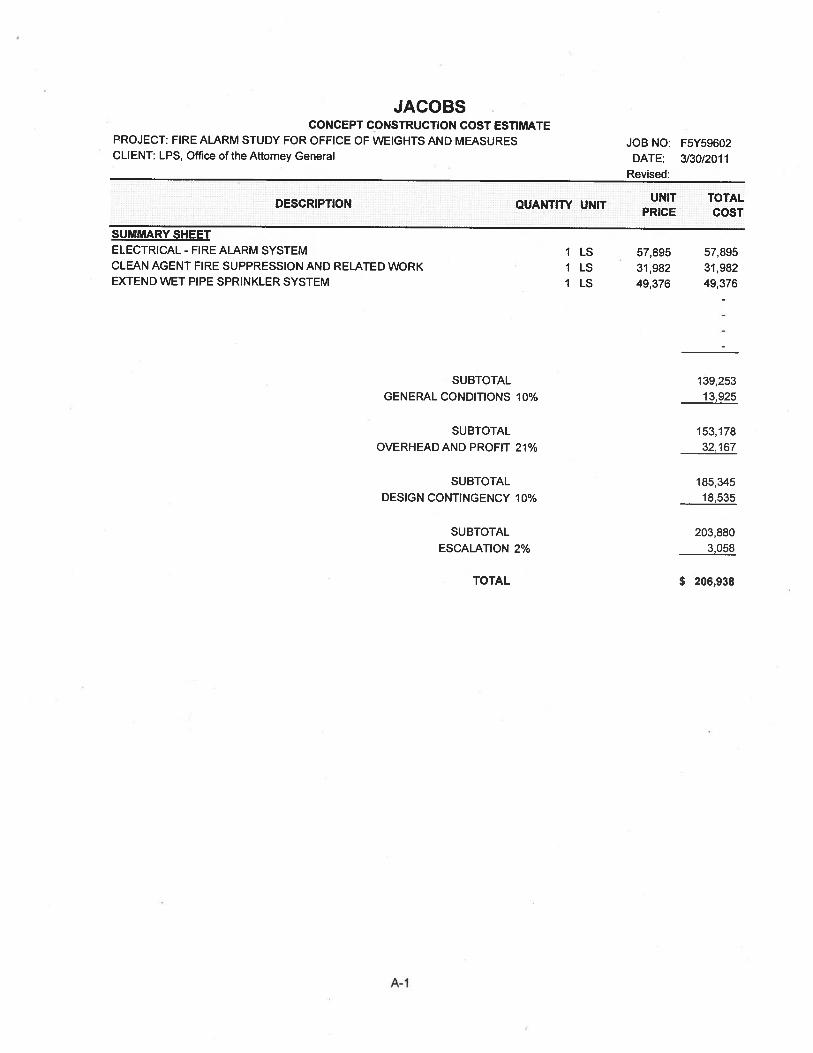
JACOBSCONCEPT CONSTRUCTION COST ESTIMATE
PROJECT: FIRE ALARM STUDY FOR OFFICE OF WEIGHTS AND MEASURESCLIENT: LPS, Office of the Attorney General
UNIT TOTALDESCRIPTION QUANTITY UNITPRICE COST
SUMMARY SHEETELECTRICAL - FIRE ALARM SYSTEMCLEAN AGENT FIRE SUPPRESSION AND RELATED WORKEXTEND WET PIPE SPRINKLER SYSTEM
SUBTOTAL 139,253GENERAL CONDITIONS 10% 13,925
SUBTOTAL 153,178OVERHEADAND PROFIT 21% 32,167
SUBTOTAL 185,345DESIGN CONTINGENCY 10% 18,535
SUBTOTAL 203,880ESCALATION 2% 3058
TOTAL $ 206,938
JOB NO: F5Y59602DATE: 3/30/2011
Revised:
1 LS 57,895I LS 31,982I LS 49,376
57,89531,98249,376
A-i
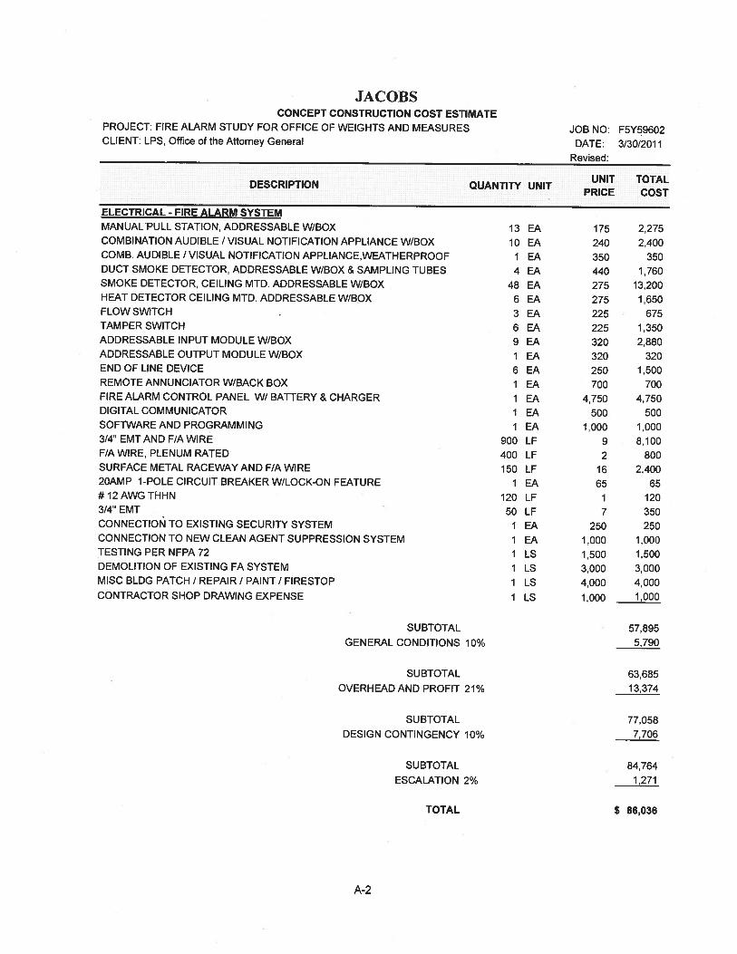
JACOBS
SUBTOTAL
GENERAL CONDITIONS 10%
SUBTOTAL
OVERHEAD AND PROFIT 21%
57,8955,790
63,68513,374
77,0587,706
84,7641,271
$ 86,036
CONCEPT CONSTRUCTION COST ESTIMATEPROJECT: FIRE ALARM STUDY FOR OFFICE OF WEIGHTS AND MEASURESCLIENT: LPS, Office of the Attorney General
Revised:
UNIT TOTALDESCRIPTION QUANTITY UNITPRICE COST
ELECTRICAL - FIRE ALARM SYSTEM
JOB NO: F5Y59602DATE: 3/30/2011
MANUAL PULL STATION, ADDRESSABLE W/BOX 13 EA 175 2,275COMBINATION AUDIBLE I VISUAL NOTIFICATION APPLIANCE W/BOX 10 EA 240 2,400COMB. AUDIBLE I VISUAL NOTIFICATION APPLIANCE,WEATHERPROOF 1 EA 350 350DUCT SMOKE DETECTOR, ADDRESSABLE W/BOX & SAMPLING TUBES 4 EA 440 1,760SMOKE DETECTOR, CEILING MTD. ADDRESSABLE W/BOX 48 EA 275 13,200HEAT DETECTOR CEILING MTD. ADDRESSABLE W/BOX 6 EA 275 1,650FLOW SWITCH 3 EA 225 675TAMPER SWITCH 6 EA 225 1,350ADDRESSABLE INPUT MODULE W/BOX 9 EA 320 2,880ADDRESSABLE OUTPUT MODULE WIBOX 1 EA 320 320END OF LINE DEVICE 6 EA 250 1,500REMOTE ANNUNCIATOR W/BACK BOX 1 EA 700 700FIRE ALARM CONTROL PANEL W/ BATTERY & CHARGER 1 EA 4,750 4,750DIGITAL COMMUNICATOR 1 EA 500 500SOFTWAREAND PROGRAMMING 1 EA 1,000 1,0003/4’ EMTAND F/A WIRE 900 LF 9 8,100F/A WIRE, PLENUM RATED 400 LF 2 800SURFACEMETALRACEWAYANDFIAWIRE 150 LF 16 2,4002OAMP 1-POLE CIRCUIT BREAKER W/LOCK-ON FEATURE 1 EA 65 65#12AWGTHHN 120 LF 1 1203/4’ EMT 50 LF 7 350CONNECTION TO EXISTING SECURITY SYSTEM 1 EA 250 250CONNECTION TO NEW CLEAN AGENT SUPPRESSION SYSTEM 1 EA 1,000 1,000TESTINGPERNFPA72 1 LS 1,500 1,500DEMOLITION OF EXISTING FA SYSTEM 1 LS 3,000 3,000MISCBLDGPATCHIREPAIRIPAINTIFIRESTOP 1 LS 4,000 4,000CONTRACTOR SHOP DRAWING EXPENSE 1 LS 1,000 1,000
SUBTOTAL
DESIGN CONTINGENCY 10%
SUBTOTAL
ESCALATION 2%
TOTAL
A-2
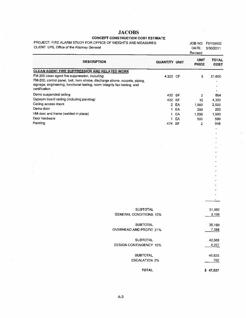
JACOBSCONCEPT CONSTRUCTION COST ESTIMATE
PROJECT: FIRE ALARM STUDY FOR OFFICE OF WEIGHTS AND MEASURESCLIENT: LPS, Office of the Attorney General
(I AN At’PMT FIRE SUPPRESSION AND RELATED WORKFM 200 clean agent fire suppression, including:FM-200, control panel, bell, horn strobe, discharge strone, nozzels, piping,signage, engineering, functional testing, room integrity fan testing, andcertification
JOB NO: F5Y59602DATE: 3/30/2011
Revised:
SUBTOTAL
GENERAL CONDITIONS 10%
SUBTOTAL
OVERHEAD AND PROFIT 21%
SUBTOTAL
DESIGN CONTINGENCY 10%
SUBTOTAL
ESCALATION 2%
31,9823,198
35,1807,388
42,5684,257
46,825702
$ 47,527
UNIT TOTALDESCRIPTION QUANTITY UNITPRICE COST
4,320 CF 5 21,600
Demo suspended ceilingGypsum board ceiling (including painting)Ceiling access doorsDemo door
HM door and frame (welded in place)Door hardwarePainting
432 SF432 SF
2 EA1 EA1 EA1 EA
474 SF
210
1.000250
1,500500
2
8644,3202,000
2501,500
500948
TOTAL
A-3
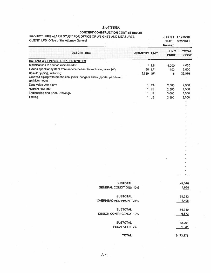
JACOBSCONCEPT CONSTRUCTION COST ESTIMATE
PROJECT: FIRE ALARM STUDY FOR OFFICE OF WEIGHTS AND MEASURESCLIENT: LPS, Office of the Attorney General
EXTEND WET PIPE SPRINKLER SYSTEMModifications to service main headerExtend sprinkler system from service header to truck wing area (4”)Spinkler piping, including:Grooved piping with mechanical joints, hangers and supports, pendenatsprinkler headsZone valve with alarmHydrant flow testEngineering and Shop DrawingsTesting
SUBTOTAL
GENERAL CONDITIONS 10%
49,3764,938
SUBTOTAL
OVERHEAD AND PROFIT 21%
SUBTOTAL
DESIGN CONTINGENCY 10%
SUBTOTAL
ESCALATION 2%
TOTAL
54,31311,406
65,7196,572
72,291
1,084
$ 73,375
UNIT TOTALDESCRIPTION QUANTITY UNITPRICE COST
JOB NO: F5Y59602DATE: 3/30/20 1 1
Revised:
I LS 4,000 4,00050 LF 100 5,000
6,639 SF 5 29,876
1 EA 2.500 2,5001 LS 2,500 2.5001 LS 3,000 3,0001 LS 2,500 2,500
A-4
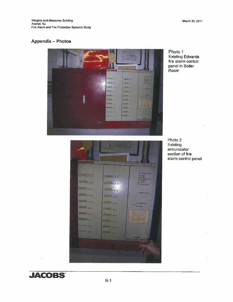
Weights and Measures BuildingAvenel, NJFire Alarm and Fire Protection Systems Study
March 30, 2011
JACOBS
Photo IExisting Edwardsfire alarm controlpanel in BoilerRoom
Photo 2Existingannunciatorsection of firealarm control panel
Appendix — Photos
B-i
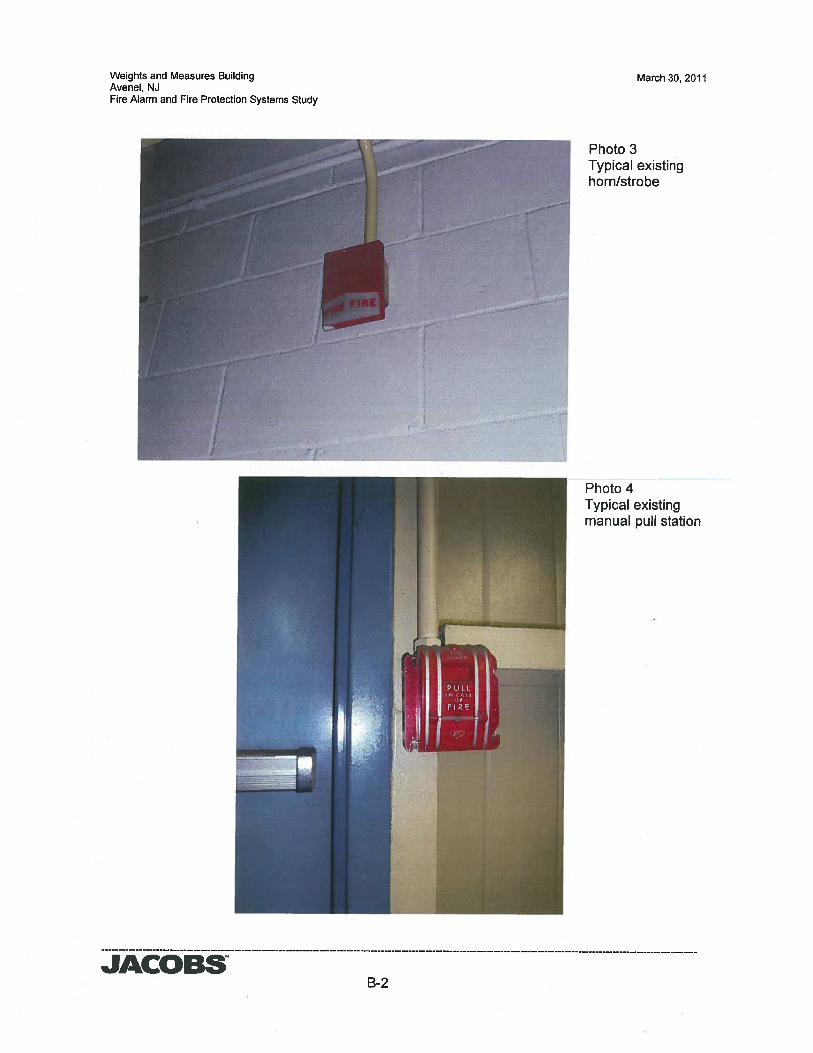
Weights and Measures BuildingAvenel, NJFire Alarm and Fire Protection Systems Study
March 30, 2011
Photo 3Typica’ existinghorn/strobe
Photo 4Typical existingmanual pull station
JACOBSB-2
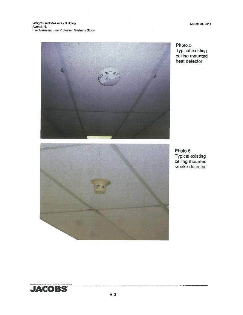
Weights and Measures BuildingAvenel, NJFire Alarm and Fire Protection Systems Study
March 30, 2011
Photo 5Typical existingceiling mountedheat detector
Photo 6Typical existingceiling mountedsmoke detector
JACOBSB-3
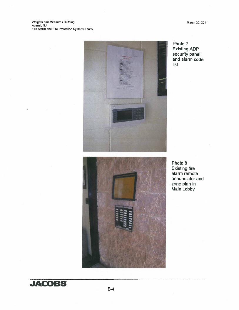
Weights and Measures BuildingAvenel, NJFire Alarm and Fire Protection Systems Study
March 30, 2011
JACOBSB-4
Photo 7Existing ADPsecurity paneland alarm codelist
Photo 8Existing firealarm remoteannunciator andzone plan inMain Lobby
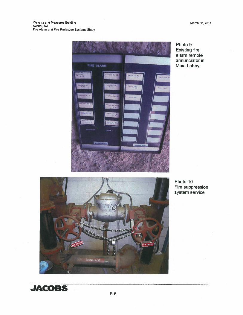
Weights and Measures BuildingAvenel, NJFire Alarm and Fire Protection Systems Study
March 30,2011
Photo 9Existing firea’arm remoteannunciator inMain Lobby
Photo 10Fire suppressionsystem service
JACOBSB-5
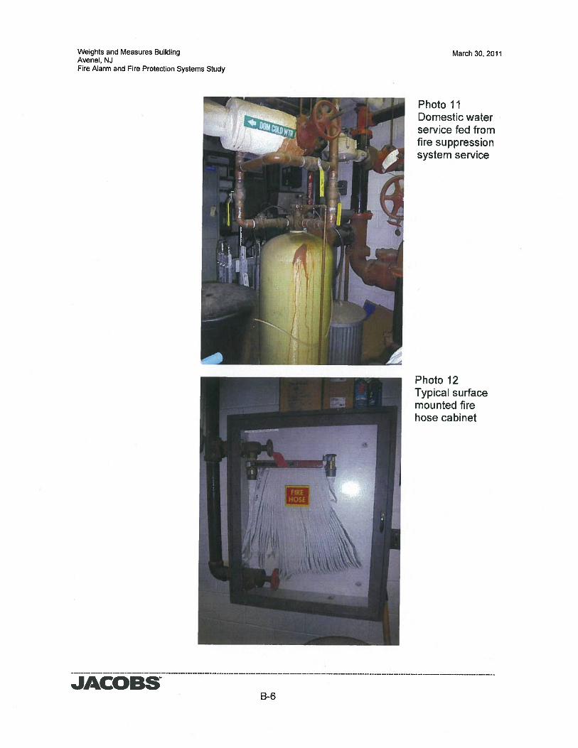
Weights and Measures BuildingAvenel, NJFire Alarm and Fire Protection Systems Study
March 30, 2011
Photo 11Domestic waterservice fed fromfire suppressionsystem service
Photo 12Typica’ surfacemounted firehose cabinet
JACOBSB-6
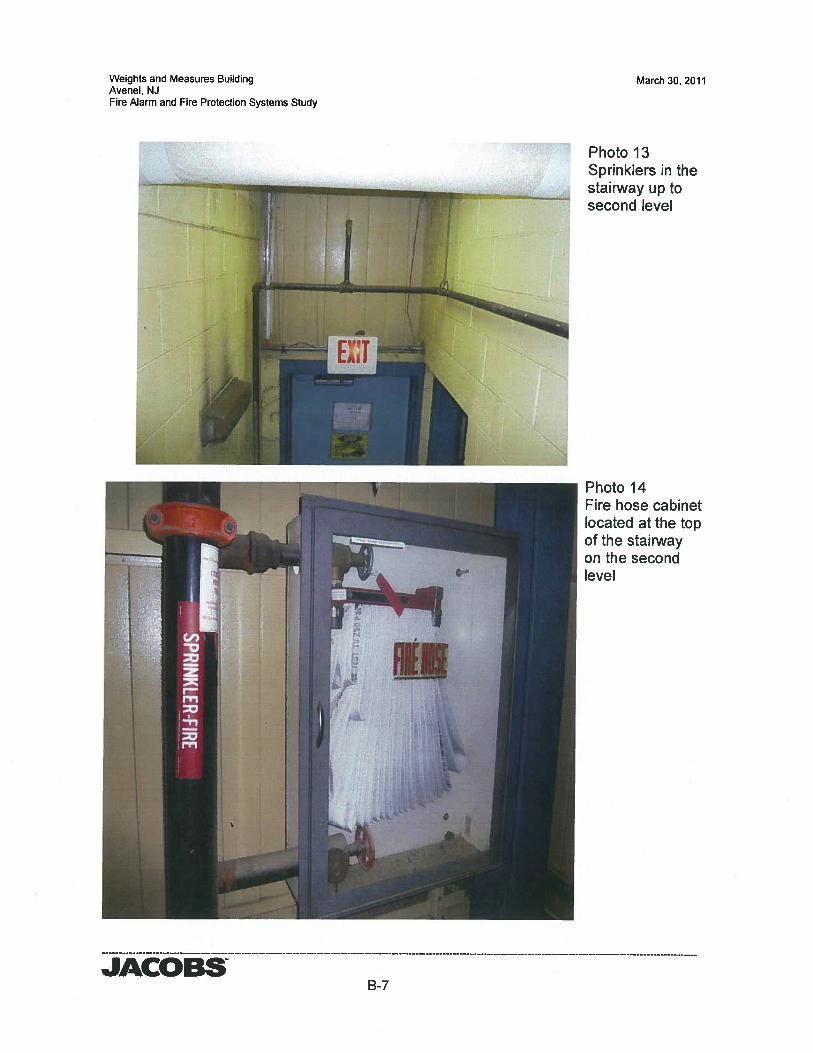
Weights and Measures BuildingAvenel, NJFire Alarm and Fire Protection Systems Study
March 30, 2011
Photo 13Sprinklers in thestairway up tosecond level
Photo 14Fire hose cabinetlocated at the topof the stairwayon the secondlevel
JACOBSB-7
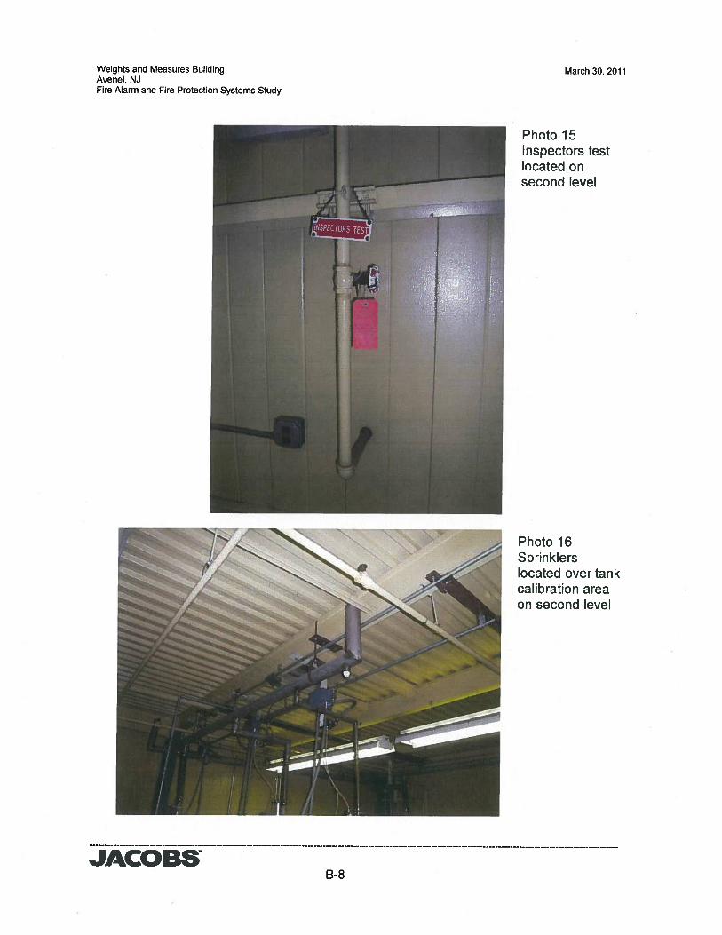
Weights and Measures BuildingAvenel, NJFire Alarm and Fire Protection Systems Study
March 30, 2011
Photo 15Inspectors testlocated onsecond level
Photo 16Sprinklerslocated over tankcalibration areaon second level
JACOBSB-8
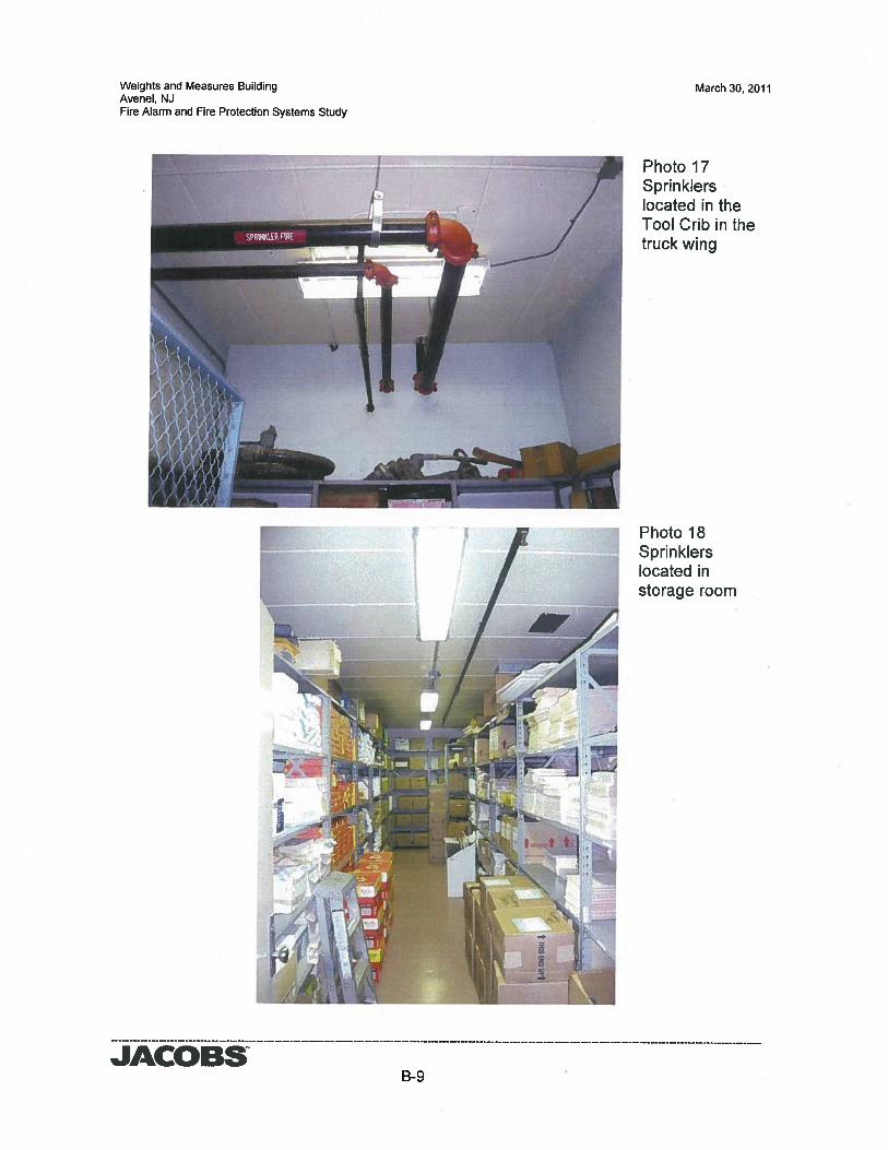
Weights and Measures BuildingAvenel, NJFire Alarm and Fire Protection Systems Study
March 30, 2011
JACOBS
Photo 17Sprinklerslocated in theTool Crib in thetruck wing
Photo 18Sprinklerslocated instorage room
B-9
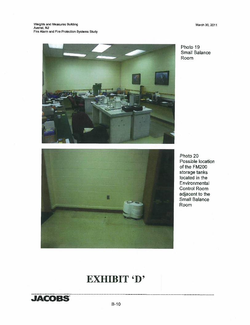
Weights and Measures BuildingAvenel, NJFire Alarm and Fire Protection Systems Study
EXHIBIT ‘D’
March 30, 2011
Photo 19Small BalanceRoom
Photo 20Possible locationof the FM200storage tankslocated in theEnvironmentalControl Roomadjacent to theSmall BalanceRoom
JACOBSB-I 0