Embed Size (px)
Citation preview
1
Project Proposal:
LED Candlelight Test Automaton
Dr. Reza Emami AER201 - Engineering Design
Qi Ran Liao 999848205 Lifu Zhang 999720280
Zhi Jin Zhang 999853911 Group 63
TA: Rehman Merali
Division of Engineering Science University of Toronto
January 24, 2014

2
Table of Contents
1. Executive Summary 5 1.1 Problem 5 1.2 Overview of Solution 5 1.3 Funding Requirements 5 1.4 Organization and Expertise 5
2. Introduction 5 2.1 Statement of Problem 5 2.2 Goals 6 2.3 Objectives 6 2.4 Stakeholders 6 2.5 Requirements 6 2.6 Constraints 6 2.7 Criteria 6
3. Conceptualization and Idea Selection 7 3.1 Functional Decomposition and Background Survey 7
3.1.1 Opening and Closing LED Switches 7 3.1.1.1 Motor Board and Metal Chip 7 3.1.1.2 Switch Test Machine by Makeblock 8
3.1.2 Detecting the Presence of Candlelights 8 3.1.2.1 Force Sensitive Resistor (FSR) 9 3.1.2.2 Photoelectric Sensor 9 3.1.2.3 Detector Switch 9
3.1.3 Inspecting the States of Functionality of Candlelights 10 3.1.3.1 Photoresistor 10 3.1.3.2 Phototransistor 10 3.1.3.3 Photodiode 11 3.1.3.4 LED Electrical Test Module Designed by Chroma 11
3.2 DFXs 12 3.2.1 Design for Efficiency 12 3.2.2 Design for Safety 12 3.2.3 Design for Robustness 12 3.2.4 Design for Feasibility 12
3.3 Alternative Solutions 12 3.3.1 Tool Box Tester 13
3.3.1.1 Overview of Structure 13 3.3.1.2 Switching Mechanism 13 3.3.1.3 Inspecting the States of Functionality of Candlelights 14 3.3.1.4 Advantages & Disadvantages 14
3.3.2 Rotating Tray Tester 15
3
3.3.2.1 Overview of Structure 15 3.3.2.2 Switching Mechanism 15 3.3.2.3 Inspecting the States of Functionality of Candlelights 16 3.3.2.4 Advantages & Disadvantages 16
3.3.3 Linear Tray Tester 16 3.3.3.1 Overview of Structure 16 3.3.3.2 Switching Mechanism 18 3.3.3.3 Inspecting the States of Functionality of Candlelights 18 3.3.3.4 Advantages & Disadvantages 18
3.4 Candidate Solution & Justifications 18 3.4.1 First Justification 18 3.4.2 Second Justification 18 3.4.3 Third Justification 19
4. Overview of Subsystems 20 4.1 Electromechanical System 20
4.1.1 Structural Design & Space Allocation 20 4.1.2 Material Selection 21 4.1.3 Estimation of Weight of Individual Components 21 4.1.4 Implementation of Switching Mechanism 21 4.1.5 Design of Lid 23 4.1.6 Implementation of Detection Mechanism 24 4.1.7 Installation of Photosensor Circuitry 25 4.1.8 Installation of Circuitry Subsystem and Microcontroller Subsystem 25 4.1.9 Emergency Stop Switch 25
4.2 Circuitry 25 4.2.1 Motor Driver Circuit 26 4.2.2 LED Candlelight Presence Detecting Circuit 26 4.2.3 Photosensor Circuit 27 4.2.4 Multiplexer 28
4.3 PIC Microcontroller 29 4.3.1 Selection of PIC Microcontroller 29 4.3.2 LCD-Keypad Interface Design 30 4.3.3 Program Flow Chart 30 4.3.4 Emergency Stop 30 4.3.5 PIC16F877 Pin Assignment 32 4.3.6 Programmer Board Selection 32
5. Schedule 34 6. Budget 35 7. Conclusion 36

4
Appendices
A. Bibliography B. PIC16F877 Microcontroller Data Sheet C. SN754410 Data Sheet D. 900 Series Detector Switch Data Sheet E. PDV-P8103 Photoresistor Data Sheet F. 74HC151 8-to-1 Multiplexers Data Sheet G. NC7SB3157P6X 2-to-1 Multiplexer Data Sheet H. Material Selection I. Weight Approximation J. Zheng DC Motor
5
1. Executive Summary 1.1 Problem This proposal presents the design and construction plan of an automated LED candlelight test machine that verifies the functionality of maximum 9 LED candlelights simultaneously under a 90 seconds runtime and additional constraints (stated in Section 2.6). 1.2 Overview of Solution A machine is designed such that the inputs from an operator are instructions through a keypad, and the placement of LED candlelights on a pre-fabricated linear tray. The machine is composed of a linear wooden tray, and a main rectangular body. The geometry of the tray forces switches to orient in a prescribed fashion such that a motor driven shaft would push individual switch parallel to length of tray. After setting up the tray, an aluminum cover would be used to isolate LED candlelight from ambient light to ensure accurate input to sensors. 9 photosensors, which are attached to the device’s main body, are used to detect light intensity and variation. A switch mechanism is used to inform the presence of LED candlelight. Operation algorithm is implemented using a PIC16F877 microcontroller. 1.3 Funding Requirements The budget of this design project is restricted to $230 CAD, and the proposed solution approximately costs $200 CAD. This funding is divided in 2 major sections: 1. cost for mechanical components; 2.cost for electronics. 1.4 Organization and Expertise This design project will be completed by a team of three engineering students: Qi Ran Liao is responsible for the electromechanical subsystem including fabrication of the automaton, Lifu Zhang is responsible for the circuitry subsystem including construction of circuits associated with sensors and motor drive, and Zhi Jin Zhang is responsible for the microcontroller subsystem including implementing the operating algorithm. 2. Introduction 2.1 Statement of Problem The product addressed in this design proposal is a package of LED candlelights produced by a LED light manufacturer. LED candlelights are widely used in festive events, and a functional LED candlelight is capable of flickering during its operation. However, manual testing of candlelight’s functionality is tedious and may slow down the production process. As a result, this manufacturer is requesting an autonomous LED candlelight testing machine that is able to test a maximum number of 9 candlelights within 90 seconds for each operation. The automaton can catalyze the testing stage, which is beneficial for the overall production process.

6
2.2 Goals Build a functional, efficient, and robust LED candlelight testing machine to inspect and record the functionality of a tray of LED candlelights, thereby speeding up the production process and reducing the cost of labor. 2.3 Objectives
1. Test a tray of, maximum 9, LED candlelights in no more than 90 seconds. 2. Record the total number of candlelights, and the inspected functionality of each
candlelight. 3. Display the information on LCD screen.
2.4 Stakeholders
1. LED manufacturer: a. Defines the requirements and constraints b. Provides funding
2. Machine operator: a. Operates the testing machine b. Should not be harmed by the machine
3. Engineers a. Design and test the solution
2.5 Requirements
1. Autonomous, the operator is only allowed to place candlelights in the tray. 2. Includes a tray that can be separated from the machine and does not contain any
electronic part; the tray must hold at least 9 candlelights. 3. Portable, without any required installation. 4. Includes an easily-accessible emergency STOP switch that halts all the mechanical parts. 5. Each operation takes a maximum of 90 seconds.
2.6 Constraints
1. Maximum dimensions: 50 cm x 50 cm x 50 cm 2. Maximum weight: 6 kg 3. Maximum cost: $230 CAD 4. Maximum operation runtime: 90 seconds
2.7 Criteria
1. Cost (measured in $CAD): lower the better 2. Size (measured in cm^3): smaller the better 3. Weight (measured in kg): lighter the better 4. Simplicity (measured in number of moving parts): lower the better

7
5. User-friendliness (measured in time taken to load/unload a tray): shorter the better 6. Reliability (measured in number of candlelights whose functionalities are correctly
determined): higher the better 7. Robustness (measured in number of operations performed before the machine breaks
down): higher the better 3. Conceptualization and Idea Selection 3.1 Functional Decomposition and Background Survey To aid the conceptual design process, the task was functionally decomposed into simpler constituents so that the original task could be solved by integrating the smaller modules together. Each functionally decomposed component is considered distinct and separated from each other:
1. Opening and closing the switches of candlelights. 2. Detecting the number of candlelights present. 3. Inspecting the states of functionality of candlelights.
3.1.1 Opening and Closing LED Switches As stated in the RFP, the candlelights are first loaded into the tray with switches closed, and should be turned off when the tray is retrieved after the operation. Therefore, the automaton should be able to open and close the LED switches during its operation. The switch on a LED candlelight is small, and requires a translational horizontal motion to slide it back and forth. The mechanisms developed from either brainstorming or the existing designs in the industry to perform this function are described in the following sections. 3.1.1.1 Motor Board and Metal Chip This is a mechanism consisting of a board with gear teeth on one side and 18 metal chips attached to the other, and a motor.
Figure 1: Motor Board Design
8
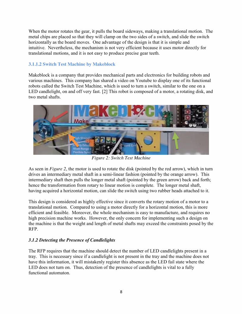
When the motor rotates the gear, it pulls the board sideways, making a translational motion. The metal chips are placed so that they will clamp on the two sides of a switch, and slide the switch horizontally as the board moves. One advantage of the design is that it is simple and intuitive. Nevertheless, the mechanism is not very efficient because it uses motor directly for translational motions, and it is not easy to produce precise gear teeth. 3.1.1.2 Switch Test Machine by Makeblock Makeblock is a company that provides mechanical parts and electronics for building robots and various machines. This company has shared a video on Youtube to display one of its functional robots called the Switch Test Machine, which is used to turn a switch, similar to the one on a LED candlelight, on and off very fast. [2] This robot is composed of a motor, a rotating disk, and two metal shafts.
Figure 2: Switch Test Machine
As seen in Figure 2, the motor is used to rotate the disk (pointed by the red arrow), which in turn drives an intermediary metal shaft in a semi-linear fashion (pointed by the orange arrow). This intermediary shaft then pulls the longer metal shaft (pointed by the green arrow) back and forth; hence the transformation from rotary to linear motion is complete. The longer metal shaft, having acquired a horizontal motion, can slide the switch using two rubber heads attached to it. This design is considered as highly effective since it converts the rotary motion of a motor to a translational motion. Compared to using a motor directly for a horizontal motion, this is more efficient and feasible. Moreover, the whole mechanism is easy to manufacture, and requires no high precision machine works. However, the only concern for implementing such a design on the machine is that the weight and length of metal shafts may exceed the constraints posed by the RFP. 3.1.2 Detecting the Presence of Candlelights The RFP requires that the machine should detect the number of LED candlelights present in a tray. This is necessary since if a candlelight is not present in the tray and the machine does not have this information, it will mistakenly register this absence as the LED fail state where the LED does not turn on. Thus, detection of the presence of candlelights is vital to a fully functional automaton.
9
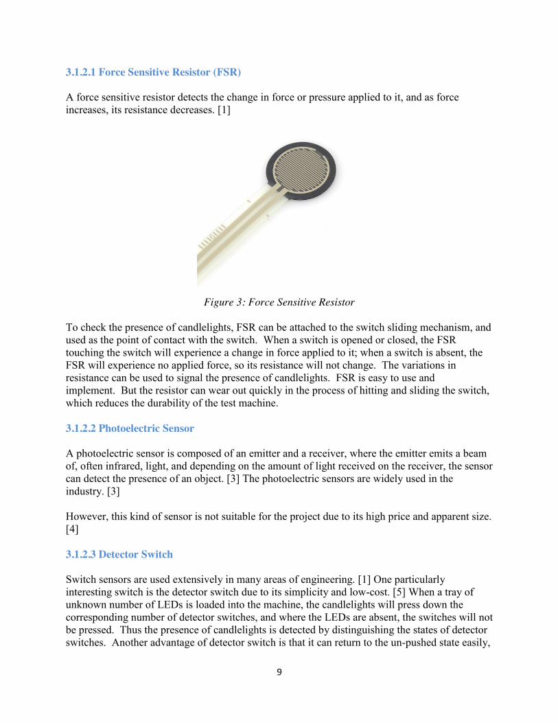
3.1.2.1 Force Sensitive Resistor (FSR) A force sensitive resistor detects the change in force or pressure applied to it, and as force increases, its resistance decreases. [1]
Figure 3: Force Sensitive Resistor
To check the presence of candlelights, FSR can be attached to the switch sliding mechanism, and used as the point of contact with the switch. When a switch is opened or closed, the FSR touching the switch will experience a change in force applied to it; when a switch is absent, the FSR will experience no applied force, so its resistance will not change. The variations in resistance can be used to signal the presence of candlelights. FSR is easy to use and implement. But the resistor can wear out quickly in the process of hitting and sliding the switch, which reduces the durability of the test machine. 3.1.2.2 Photoelectric Sensor A photoelectric sensor is composed of an emitter and a receiver, where the emitter emits a beam of, often infrared, light, and depending on the amount of light received on the receiver, the sensor can detect the presence of an object. [3] The photoelectric sensors are widely used in the industry. [3] However, this kind of sensor is not suitable for the project due to its high price and apparent size. [4] 3.1.2.3 Detector Switch Switch sensors are used extensively in many areas of engineering. [1] One particularly interesting switch is the detector switch due to its simplicity and low-cost. [5] When a tray of unknown number of LEDs is loaded into the machine, the candlelights will press down the corresponding number of detector switches, and where the LEDs are absent, the switches will not be pressed. Thus the presence of candlelights is detected by distinguishing the states of detector switches. Another advantage of detector switch is that it can return to the un-pushed state easily,
10
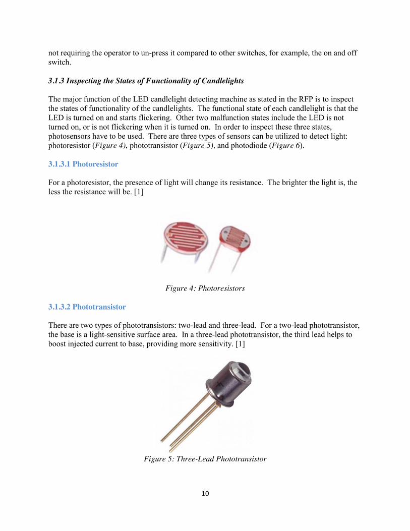
not requiring the operator to un-press it compared to other switches, for example, the on and off switch. 3.1.3 Inspecting the States of Functionality of Candlelights The major function of the LED candlelight detecting machine as stated in the RFP is to inspect the states of functionality of the candlelights. The functional state of each candlelight is that the LED is turned on and starts flickering. Other two malfunction states include the LED is not turned on, or is not flickering when it is turned on. In order to inspect these three states, photosensors have to be used. There are three types of sensors can be utilized to detect light: photoresistor (Figure 4), phototransistor (Figure 5), and photodiode (Figure 6). 3.1.3.1 Photoresistor For a photoresistor, the presence of light will change its resistance. The brighter the light is, the less the resistance will be. [1]
Figure 4: Photoresistors
3.1.3.2 Phototransistor There are two types of phototransistors: two-lead and three-lead. For a two-lead phototransistor, the base is a light-sensitive surface area. In a three-lead phototransistor, the third lead helps to boost injected current to base, providing more sensitivity. [1]
Figure 5: Three-Lead Phototransistor
11
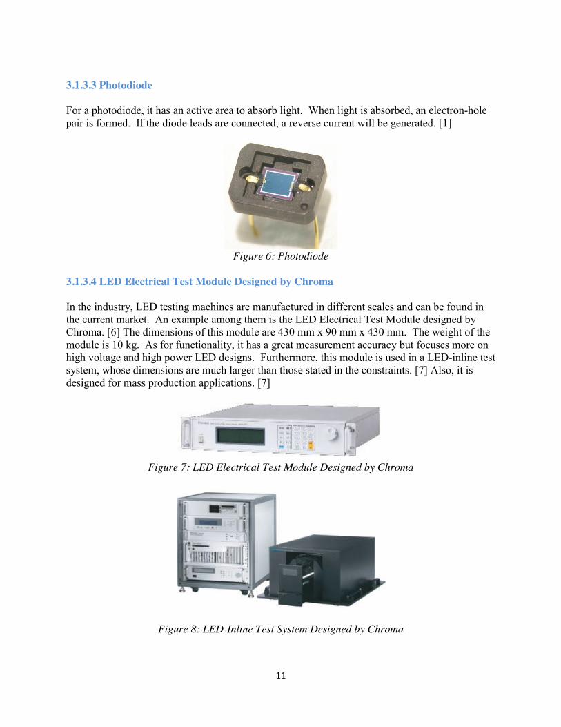
3.1.3.3 Photodiode For a photodiode, it has an active area to absorb light. When light is absorbed, an electron-hole pair is formed. If the diode leads are connected, a reverse current will be generated. [1]
Figure 6: Photodiode
3.1.3.4 LED Electrical Test Module Designed by Chroma In the industry, LED testing machines are manufactured in different scales and can be found in the current market. An example among them is the LED Electrical Test Module designed by Chroma. [6] The dimensions of this module are 430 mm x 90 mm x 430 mm. The weight of the module is 10 kg. As for functionality, it has a great measurement accuracy but focuses more on high voltage and high power LED designs. Furthermore, this module is used in a LED-inline test system, whose dimensions are much larger than those stated in the constraints. [7] Also, it is designed for mass production applications. [7]
Figure 7: LED Electrical Test Module Designed by Chroma
Figure 8: LED-Inline Test System Designed by Chroma

12
3.2 DFXs The design team has determined the following DFX for guiding the conceptual design and solution selection process. 3.2.1 Design for Efficiency Due to the constraints defined by the client, the operation runtime must be less than 90 seconds. As a result, the candidate solution must provide a correct testing of LED candlelights under this time limit. 3.2.2 Design for Safety The automaton must not pose any hazard to its user, i.e. no sharp edges or exposed electrical wire. 3.2.3 Design for Robustness The machine must be designed to be structurally stable and durable for a reasonable period of time. 3.2.4 Design for Feasibility The construction of the machine should be feasible and does not require much work with high precision. 3.3 Alternative Solutions There are 3 different conceptual designs.
13
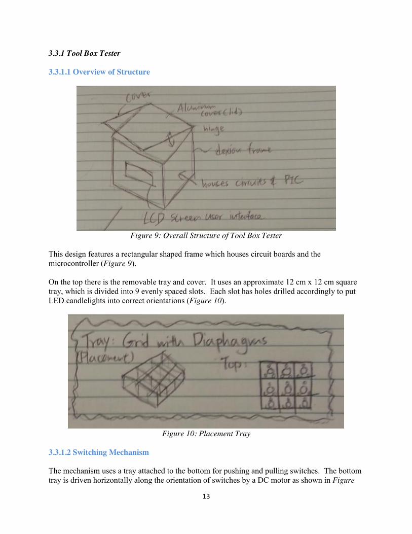
3.3.1 Tool Box Tester 3.3.1.1 Overview of Structure
Figure 9: Overall Structure of Tool Box Tester
This design features a rectangular shaped frame which houses circuit boards and the microcontroller (Figure 9). On the top there is the removable tray and cover. It uses an approximate 12 cm x 12 cm square tray, which is divided into 9 evenly spaced slots. Each slot has holes drilled accordingly to put LED candlelights into correct orientations (Figure 10).
Figure 10: Placement Tray
3.3.1.2 Switching Mechanism The mechanism uses a tray attached to the bottom for pushing and pulling switches. The bottom tray is driven horizontally along the orientation of switches by a DC motor as shown in Figure
14
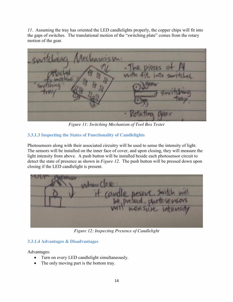
11. Assuming the tray has oriented the LED candlelights properly, the copper chips will fit into the gaps of switches. The translational motion of the “switching plate” comes from the rotary motion of the gear.
Figure 11: Switching Mechanism of Tool Box Tester
3.3.1.3 Inspecting the States of Functionality of Candlelights Photosensors along with their associated circuitry will be used to sense the intensity of light. The sensors will be installed on the inner face of cover, and upon closing, they will measure the light intensity from above. A push button will be installed beside each photosensor circuit to detect the state of presence as shown in Figure 12. The push button will be pressed down upon closing if the LED candlelight is present.
Figure 12: Inspecting Presence of Candlelight
3.3.1.4 Advantages & Disadvantages Advantages:
x Turn on every LED candlelight simultaneously. x The only moving part is the bottom tray.
15
x Has the smallest tray size among the three conceptual designs.
Disadvantages: x Requires many motors or actuators to perform the switching mechanism. x The LED candlelight placed at the center of the tray is hard to test.
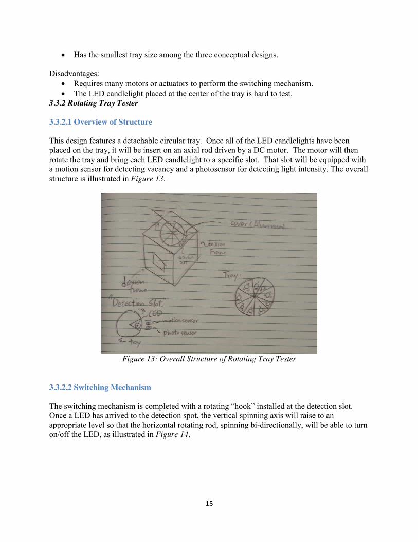
3.3.2 Rotating Tray Tester 3.3.2.1 Overview of Structure This design features a detachable circular tray. Once all of the LED candlelights have been placed on the tray, it will be insert on an axial rod driven by a DC motor. The motor will then rotate the tray and bring each LED candlelight to a specific slot. That slot will be equipped with a motion sensor for detecting vacancy and a photosensor for detecting light intensity. The overall structure is illustrated in Figure 13.
Figure 13: Overall Structure of Rotating Tray Tester
3.3.2.2 Switching Mechanism The switching mechanism is completed with a rotating “hook” installed at the detection slot. Once a LED has arrived to the detection spot, the vertical spinning axis will raise to an appropriate level so that the horizontal rotating rod, spinning bi-directionally, will be able to turn on/off the LED, as illustrated in Figure 14.

16
Figure 14: Rotating Tray Tester Switching Mechanism
3.3.2.3 Inspecting the States of Functionality of Candlelights The action of detecting presence is accomplished by using a photoelectric sensor. Photosensors will be used to sense the intensity of LED light. 3.3.2.4 Advantages & Disadvantages Advantage:
x Simple circuit configuration and operation algorithm. Disadvantages:
x Too many moving parts which are vulnerable to jamming. x LED candlelights are checked individually instead of simultaneously, which is
inefficient. 3.3.3 Linear Tray Tester 3.3.3.1 Overview of Structure This design features a linear 4 cm x 36 cm tray evenly divided into nine 4 cm x 4 cm slots. The overall geometry is illustrated in Figure 15. Since this solution will be candidate solution, detailed descriptions will be provided in Section 4.
17
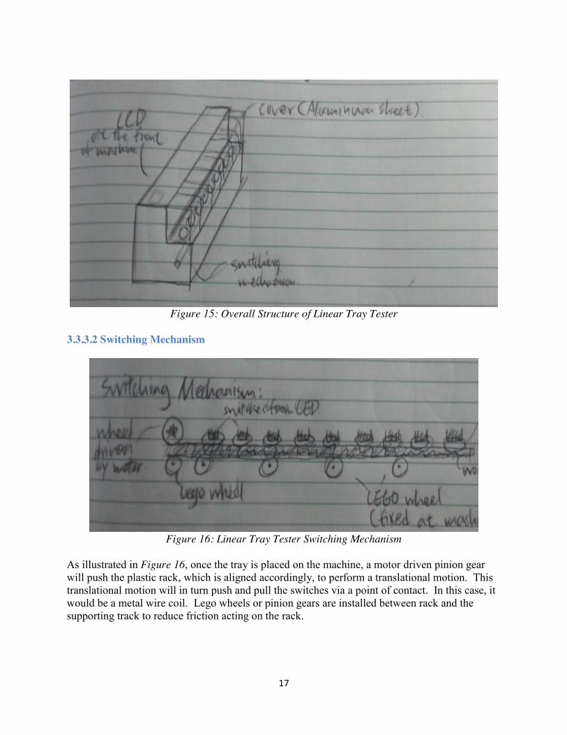
Figure 15: Overall Structure of Linear Tray Tester
3.3.3.2 Switching Mechanism
Figure 16: Linear Tray Tester Switching Mechanism
As illustrated in Figure 16, once the tray is placed on the machine, a motor driven pinion gear will push the plastic rack, which is aligned accordingly, to perform a translational motion. This translational motion will in turn push and pull the switches via a point of contact. In this case, it would be a metal wire coil. Lego wheels or pinion gears are installed between rack and the supporting track to reduce friction acting on the rack.
18
3.3.3.3 Inspecting the States of Functionality of Candlelights
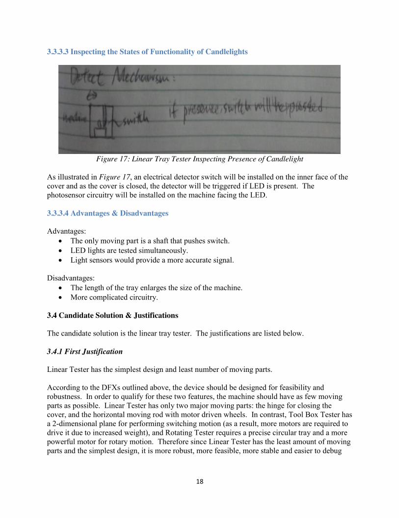
Figure 17: Linear Tray Tester Inspecting Presence of Candlelight
As illustrated in Figure 17, an electrical detector switch will be installed on the inner face of the cover and as the cover is closed, the detector will be triggered if LED is present. The photosensor circuitry will be installed on the machine facing the LED. 3.3.3.4 Advantages & Disadvantages Advantages:
x The only moving part is a shaft that pushes switch. x LED lights are tested simultaneously. x Light sensors would provide a more accurate signal.
Disadvantages:
x The length of the tray enlarges the size of the machine. x More complicated circuitry.
3.4 Candidate Solution & Justifications The candidate solution is the linear tray tester. The justifications are listed below. 3.4.1 First Justification Linear Tester has the simplest design and least number of moving parts. According to the DFXs outlined above, the device should be designed for feasibility and robustness. In order to qualify for these two features, the machine should have as few moving parts as possible. Linear Tester has only two major moving parts: the hinge for closing the cover, and the horizontal moving rod with motor driven wheels. In contrast, Tool Box Tester has a 2-dimensional plane for performing switching motion (as a result, more motors are required to drive it due to increased weight), and Rotating Tester requires a precise circular tray and a more powerful motor for rotary motion. Therefore since Linear Tester has the least amount of moving parts and the simplest design, it is more robust, more feasible, more stable and easier to debug
19
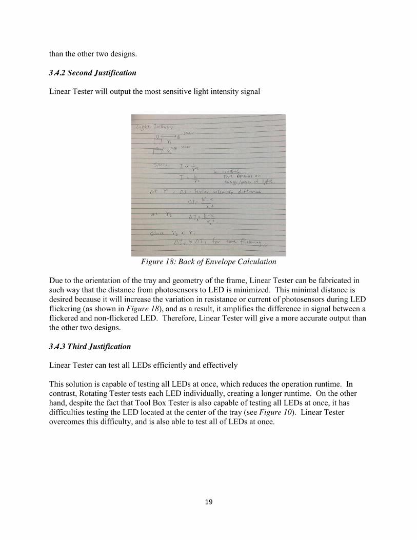
than the other two designs. 3.4.2 Second Justification Linear Tester will output the most sensitive light intensity signal
Figure 18: Back of Envelope Calculation
Due to the orientation of the tray and geometry of the frame, Linear Tester can be fabricated in such way that the distance from photosensors to LED is minimized. This minimal distance is desired because it will increase the variation in resistance or current of photosensors during LED flickering (as shown in Figure 18), and as a result, it amplifies the difference in signal between a flickered and non-flickered LED. Therefore, Linear Tester will give a more accurate output than the other two designs. 3.4.3 Third Justification Linear Tester can test all LEDs efficiently and effectively This solution is capable of testing all LEDs at once, which reduces the operation runtime. In contrast, Rotating Tester tests each LED individually, creating a longer runtime. On the other hand, despite the fact that Tool Box Tester is also capable of testing all LEDs at once, it has difficulties testing the LED located at the center of the tray (see Figure 10). Linear Tester overcomes this difficulty, and is also able to test all of LEDs at once.
20
4. Overview of Subsystems 4.1 Electromechanical System This section describes the design of the electromechanical subsystem in a greater detail. It includes: approximate dimensions, choice of materials, approximate weight, implementation of the switching mechanism, design of the lid, implementation of the detecting mechanism and installation of microcontroller and circuitry subsystems. 4.1.1 Structural Design & Space Allocation
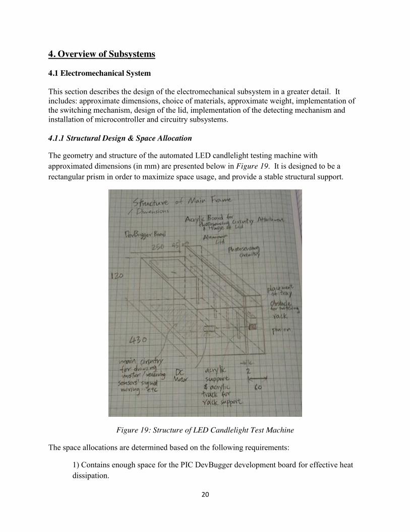
The geometry and structure of the automated LED candlelight testing machine with approximated dimensions (in mm) are presented below in Figure 19. It is designed to be a rectangular prism in order to maximize space usage, and provide a stable structural support.
Figure 19: Structure of LED Candlelight Test Machine
The space allocations are determined based on the following requirements:
1) Contains enough space for the PIC DevBugger development board for effective heat dissipation.

21
2) The tray should be detachable from the machine without disassembling any parts.
3) Actuators and wires should be housed properly to avoid safety issues.
4.1.2 Material Selection
Material information is obtained from Engineering Tool Box [8] and listed in Appendix H.
1) The frame: the frame is fabricated from aluminum. The frame has to provide a stable structural support and also does not exceed the weight limit. From the material properties listed in Appendix H, aluminum is approximately 4/5 the strength of steel but nearly 4 times lighter. Wood has the disadvantage of taking too much space, and chipping easily. Therefore, the main frame is made of aluminum.
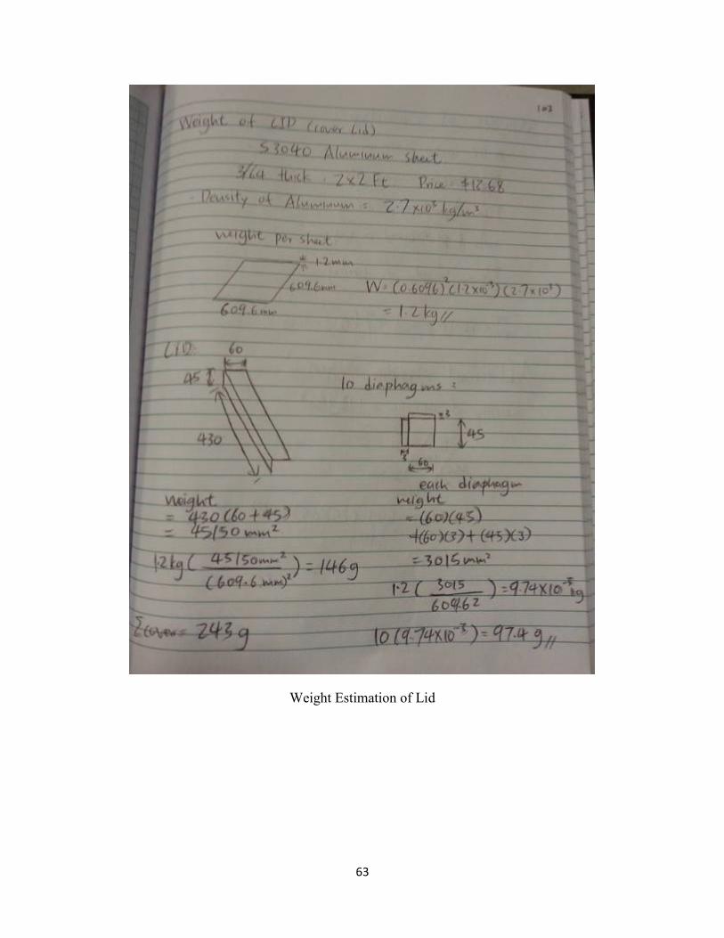
2) The lid: the lid is fabricated from an aluminum sheet. Since an aluminum sheet
bending machine is available in the machine shop, it can be fabricated precisely. Also, an aluminum sheet is reflective and can reflect light into the photosensors which helps the flickering detection algorithm to detect flickering more precisely. S3040 Aluminum Sheet is the candidate material.
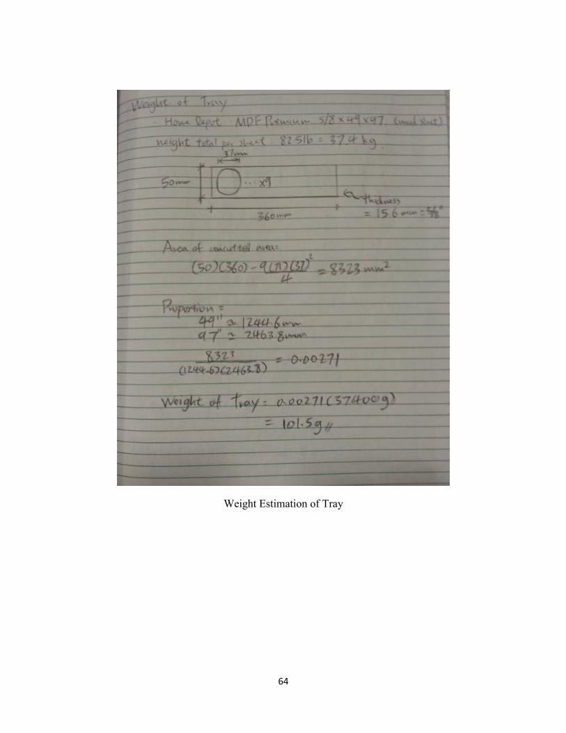
3) The tray: the tray is made of wood. Wood is light and has enough strength for
supporting candlelights. It is also thick enough to holding the case of LED candlelight.
4) Additional supports: additional structural supports for circuitry, a track for holding
mechanisms and machine base, etc., are fabricated from either acrylic sheet or wood, since they are light and have considerable strength.
4.1.3 Estimation of Weight of Individual Components
The calculation is shown in Appendix I.
Table 1: Weight of Individual Components
Material Used Total Weight (kg) Main Structural Frame 15 x 15 x 600 Aluminum Tube 0.1869 Tray MDF Premium (Wood) 0.1015 Lid S3040 Aluminum Sheet 0.243 Circuitry Electronics & DevBugger 1.47 Support & Mechanism Acrylic Sheet 2.0 Total 4.0
4.1.4 Implementation of Switching Mechanism
The drawing of the mechanism with approximated dimensions is illustrated in Figure 20.
22
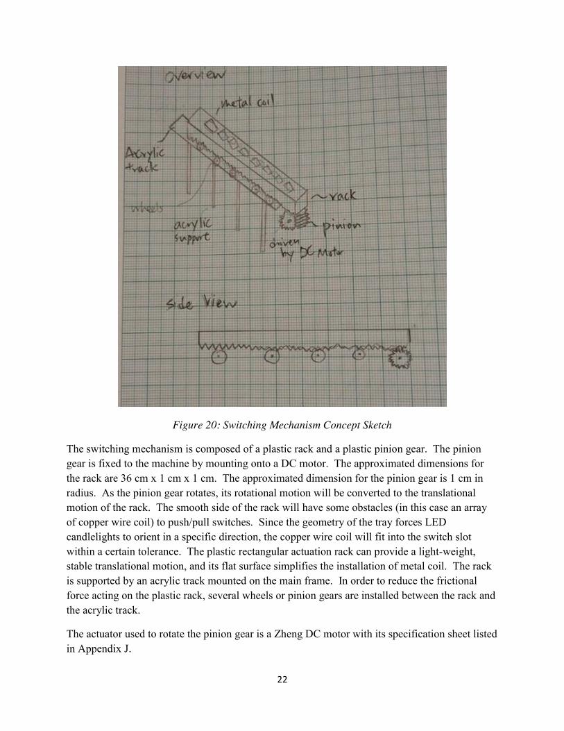
Figure 20: Switching Mechanism Concept Sketch
The switching mechanism is composed of a plastic rack and a plastic pinion gear. The pinion gear is fixed to the machine by mounting onto a DC motor. The approximated dimensions for the rack are 36 cm x 1 cm x 1 cm. The approximated dimension for the pinion gear is 1 cm in radius. As the pinion gear rotates, its rotational motion will be converted to the translational motion of the rack. The smooth side of the rack will have some obstacles (in this case an array of copper wire coil) to push/pull switches. Since the geometry of the tray forces LED candlelights to orient in a specific direction, the copper wire coil will fit into the switch slot within a certain tolerance. The plastic rectangular actuation rack can provide a light-weight, stable translational motion, and its flat surface simplifies the installation of metal coil. The rack is supported by an acrylic track mounted on the main frame. In order to reduce the frictional force acting on the plastic rack, several wheels or pinion gears are installed between the rack and the acrylic track.
The actuator used to rotate the pinion gear is a Zheng DC motor with its specification sheet listed in Appendix J.
23
The justification for using a DC motor is as follow:
1) DC motor requires less circuitry than stepper motor and servo motor. As a result, it simplifies the design of machine satisfying the DFXs.
2) DC motor provides enough torque to perform the switching action. Its approximation is shown below: Pw = power of motor ~ 5w N = # of rotation per minute ~ 30 Then the max torque provided by motor is given by:
T = (9.554)𝑝 𝑛 = 1.59 𝑁.𝑚
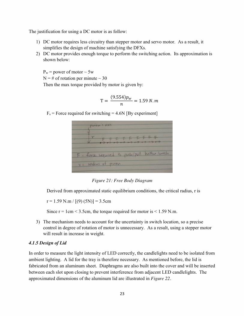
Fs = Force required for switching = 4.6N [By experiment]
Figure 21: Free Body Diagram
Derived from approximated static equilibrium conditions, the critical radius, r is
r = 1.59 N.m / [(9) (5N)] = 3.5cm
Since r = 1cm < 3.5cm, the torque required for motor is < 1.59 N.m.
3) The mechanism needs to account for the uncertainty in switch location, so a precise control in degree of rotation of motor is unnecessary. As a result, using a stepper motor will result in increase in weight.
4.1.5 Design of Lid
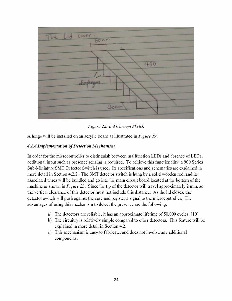
In order to measure the light intensity of LED correctly, the candlelights need to be isolated from ambient lighting. A lid for the tray is therefore necessary. As mentioned before, the lid is fabricated from an aluminum sheet. Diaphragms are also built into the cover and will be inserted between each slot upon closing to prevent interference from adjacent LED candlelights. The approximated dimensions of the aluminum lid are illustrated in Figure 22.
24
Figure 22: Lid Concept Sketch
A hinge will be installed on an acrylic board as illustrated in Figure 19.
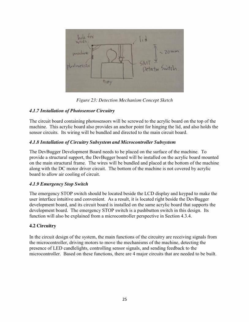
4.1.6 Implementation of Detection Mechanism
In order for the microcontroller to distinguish between malfunction LEDs and absence of LEDs, additional input such as presence sensing is required. To achieve this functionality, a 900 Series Sub-Miniature SMT Detector Switch is used. Its specifications and schematics are explained in more detail in Section 4.2.2. The SMT detector switch is hung by a solid wooden rod, and its associated wires will be bundled and go into the main circuit board located at the bottom of the machine as shown in Figure 23. Since the tip of the detector will travel approximately 2 mm, so the vertical clearance of this detector must not include this distance. As the lid closes, the detector switch will push against the case and register a signal to the microcontroller. The advantages of using this mechanism to detect the presence are the following:
a) The detectors are reliable, it has an approximate lifetime of 50,000 cycles. [10] b) The circuitry is relatively simple compared to other detectors. This feature will be
explained in more detail in Section 4.2. c) This mechanism is easy to fabricate, and does not involve any additional
components.
25
Figure 23: Detection Mechanism Concept Sketch
4.1.7 Installation of Photosensor Circuitry
The circuit board containing photosensors will be screwed to the acrylic board on the top of the machine. This acrylic board also provides an anchor point for hinging the lid, and also holds the sensor circuits. Its wiring will be bundled and directed to the main circuit board.
4.1.8 Installation of Circuitry Subsystem and Microcontroller Subsystem
The DevBugger Development Board needs to be placed on the surface of the machine. To provide a structural support, the DevBugger board will be installed on the acrylic board mounted on the main structural frame. The wires will be bundled and placed at the bottom of the machine along with the DC motor driver circuit. The bottom of the machine is not covered by acrylic board to allow air cooling of circuit.
4.1.9 Emergency Stop Switch
The emergency STOP switch should be located beside the LCD display and keypad to make the user interface intuitive and convenient. As a result, it is located right beside the DevBugger development board, and its circuit board is installed on the same acrylic board that supports the development board. The emergency STOP switch is a pushbutton switch in this design. Its function will also be explained from a microcontroller perspective in Section 4.3.4.
4.2 Circuitry In the circuit design of the system, the main functions of the circuitry are receiving signals from the microcontroller, driving motors to move the mechanisms of the machine, detecting the presence of LED candlelights, controlling sensor signals, and sending feedback to the microcontroller. Based on these functions, there are 4 major circuits that are needed to be built.
26
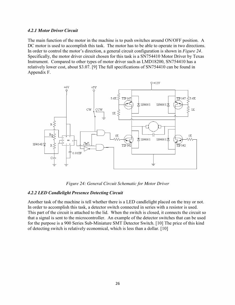
4.2.1 Motor Driver Circuit
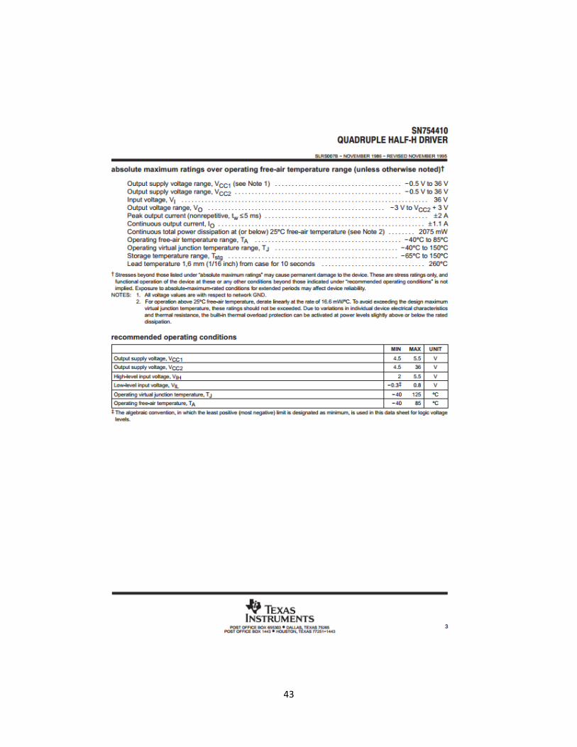
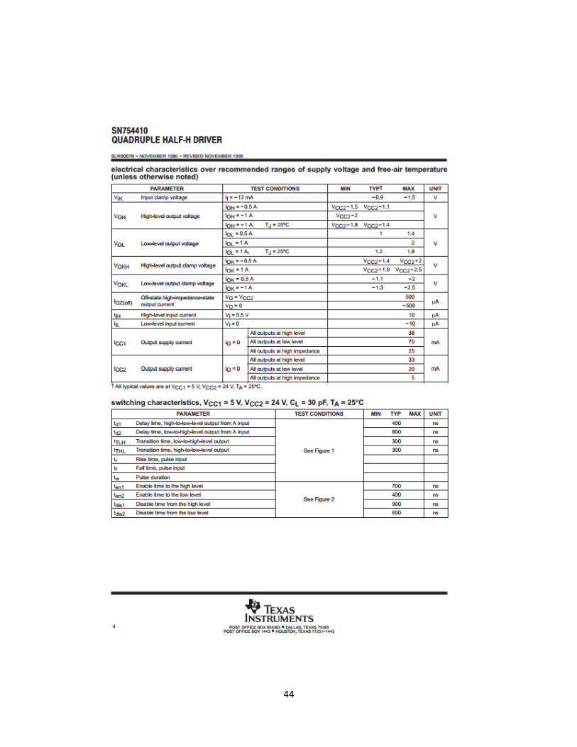
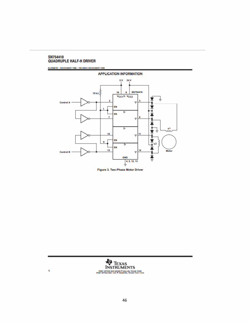
The main function of the motor in the machine is to push switches around ON/OFF position. A DC motor is used to accomplish this task. The motor has to be able to operate in two directions. In order to control the motor’s direction, a general circuit configuration is shown in Figure 24. Specifically, the motor driver circuit chosen for this task is a SN754410 Motor Driver by Texas Instrument. Compared to other types of motor driver such as LMD18200, SN754410 has a relatively lower cost, about $3.07. [9] The full specifications of SN754410 can be found in Appendix F.
Figure 24: General Circuit Schematic for Motor Driver
4.2.2 LED Candlelight Presence Detecting Circuit
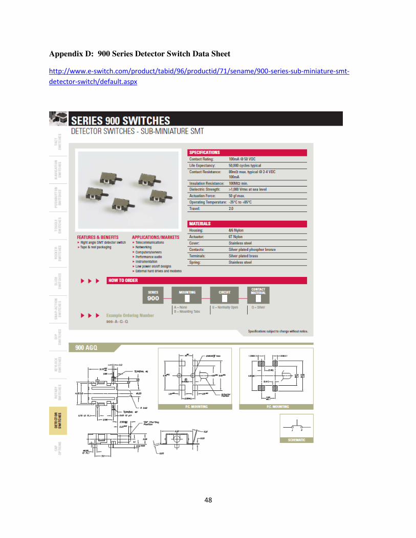
Another task of the machine is tell whether there is a LED candlelight placed on the tray or not. In order to accomplish this task, a detector switch connected in series with a resistor is used. This part of the circuit is attached to the lid. When the switch is closed, it connects the circuit so that a signal is sent to the microcontroller. An example of the detector switches that can be used for the purpose is a 900 Series Sub-Miniature SMT Detector Switch. [10] The price of this kind of detecting switch is relatively economical, which is less than a dollar. [10]
27
Figure 25: Detecting Switch Schematic
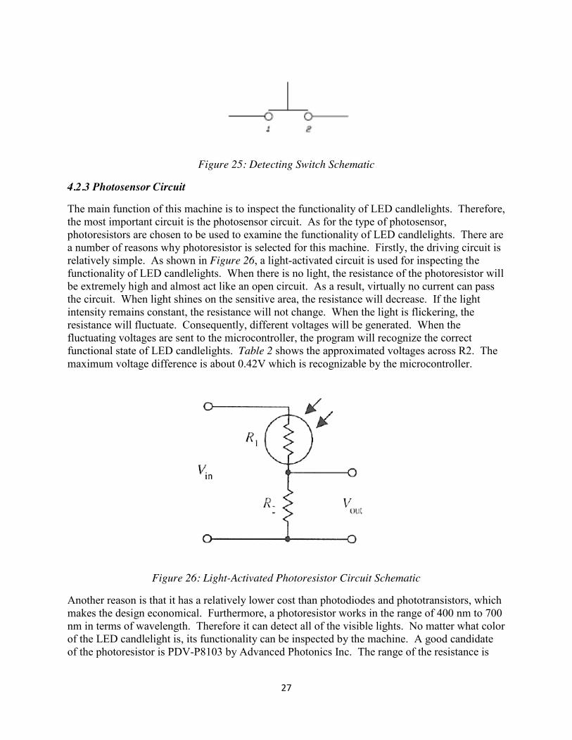
4.2.3 Photosensor Circuit
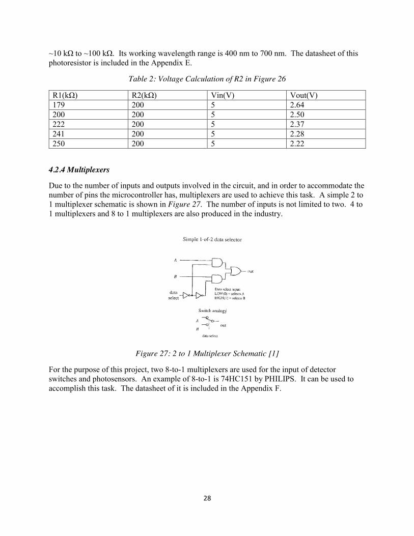
The main function of this machine is to inspect the functionality of LED candlelights. Therefore, the most important circuit is the photosensor circuit. As for the type of photosensor, photoresistors are chosen to be used to examine the functionality of LED candlelights. There are a number of reasons why photoresistor is selected for this machine. Firstly, the driving circuit is relatively simple. As shown in Figure 26, a light-activated circuit is used for inspecting the functionality of LED candlelights. When there is no light, the resistance of the photoresistor will be extremely high and almost act like an open circuit. As a result, virtually no current can pass the circuit. When light shines on the sensitive area, the resistance will decrease. If the light intensity remains constant, the resistance will not change. When the light is flickering, the resistance will fluctuate. Consequently, different voltages will be generated. When the fluctuating voltages are sent to the microcontroller, the program will recognize the correct functional state of LED candlelights. Table 2 shows the approximated voltages across R2. The maximum voltage difference is about 0.42V which is recognizable by the microcontroller.
Figure 26: Light-Activated Photoresistor Circuit Schematic
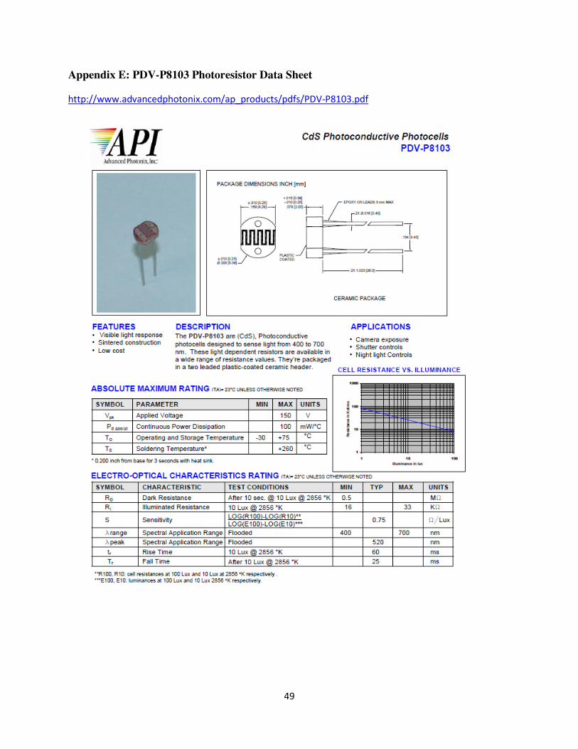
Another reason is that it has a relatively lower cost than photodiodes and phototransistors, which makes the design economical. Furthermore, a photoresistor works in the range of 400 nm to 700 nm in terms of wavelength. Therefore it can detect all of the visible lights. No matter what color of the LED candlelight is, its functionality can be inspected by the machine. A good candidate of the photoresistor is PDV-P8103 by Advanced Photonics Inc. The range of the resistance is
28
~10 kΩ to ~100 kΩ. Its working wavelength range is 400 nm to 700 nm. The datasheet of this photoresistor is included in the Appendix E.
Table 2: Voltage Calculation of R2 in Figure 26
R1(kΩ) R2(kΩ) Vin(V) Vout(V) 179 200 5 2.64 200 200 5 2.50 222 200 5 2.37 241 200 5 2.28 250 200 5 2.22
4.2.4 Multiplexers
Due to the number of inputs and outputs involved in the circuit, and in order to accommodate the number of pins the microcontroller has, multiplexers are used to achieve this task. A simple 2 to 1 multiplexer schematic is shown in Figure 27. The number of inputs is not limited to two. 4 to 1 multiplexers and 8 to 1 multiplexers are also produced in the industry.
Figure 27: 2 to 1 Multiplexer Schematic [1]
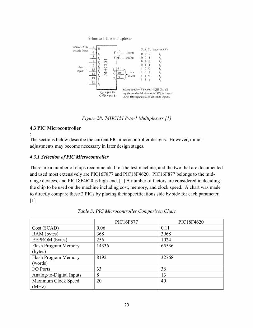
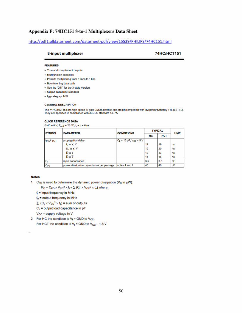
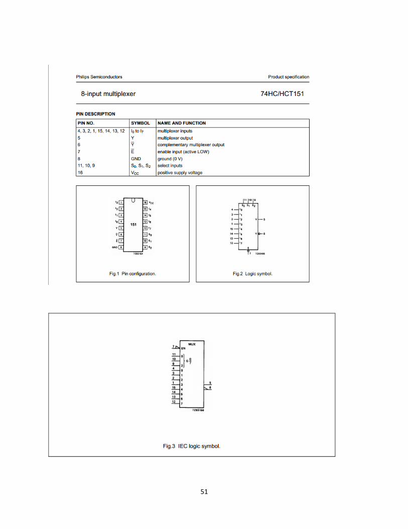
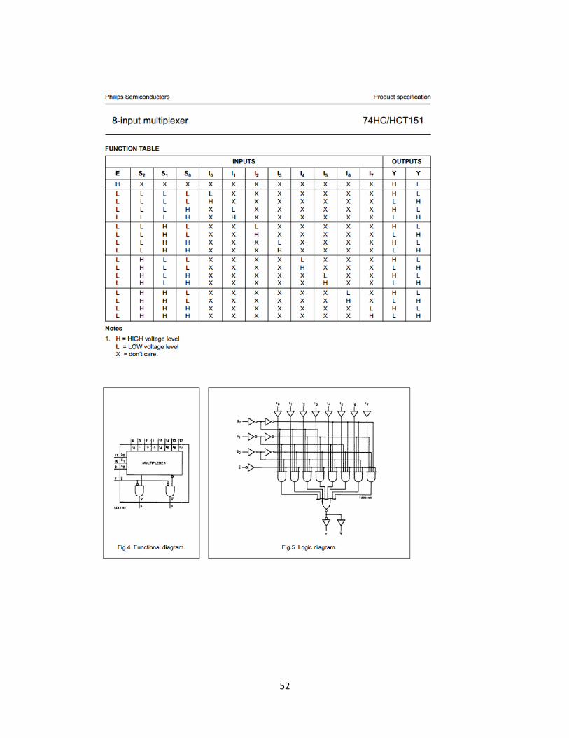
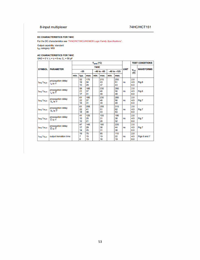
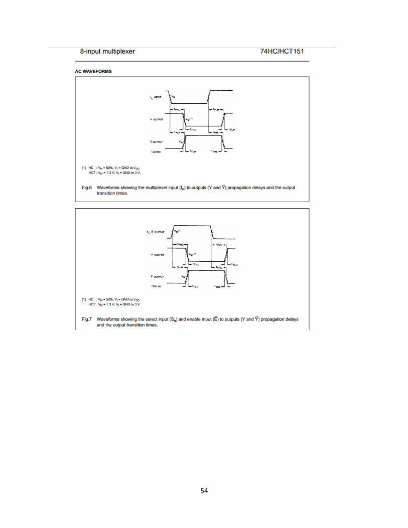
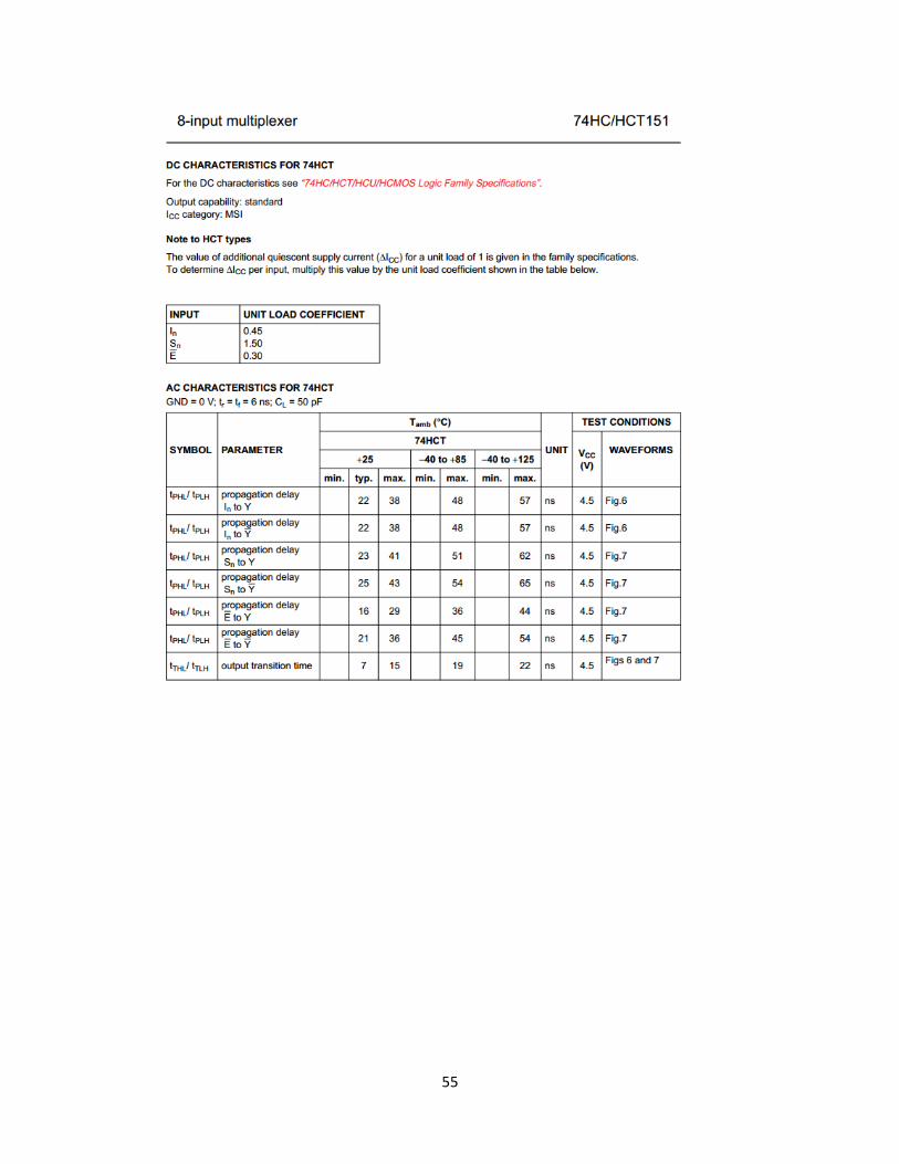
For the purpose of this project, two 8-to-1 multiplexers are used for the input of detector switches and photosensors. An example of 8-to-1 is 74HC151 by PHILIPS. It can be used to accomplish this task. The datasheet of it is included in the Appendix F.
29
Figure 28: 74HC151 8-to-1 Multiplexers [1]
4.3 PIC Microcontroller : The sections below describe the current PIC microcontroller designs. However, minor adjustments may become necessary in later design stages.
4.3.1 Selection of PIC Microcontroller
There are a number of chips recommended for the test machine, and the two that are documented and used most extensively are PIC16F877 and PIC18F4620. PIC16F877 belongs to the mid-range devices, and PIC18F4620 is high-end. [1] A number of factors are considered in deciding the chip to be used on the machine including cost, memory, and clock speed. A chart was made to directly compare these 2 PICs by placing their specifications side by side for each parameter. [1]
Table 3: PIC Microcontroller Comparison Chart
PIC16F877 PIC18F4620 Cost ($CAD) 0.06 0.11 RAM (bytes) 368 3968 EEPROM (bytes) 256 1024 Flash Program Memory (bytes)
14336 65536
Flash Program Memory (words)
8192 32768
I/O Ports 33 36 Analog-to-Digital Inputs 8 13 Maximum Clock Speed (MHz)
20 40

30
As seen from the chart, the memory capacities and speed of PIC18 are much larger than those of PIC16; however, for the purpose of this test machine, the memory and clock speed of PIC16 are considered enough for all the tasks. Also, there are not much difference between the two for other important factors such as the number of I/O ports and analog inputs which will be used for light sensors, and the cost of PIC16 is cheaper than that of PIC18. Importantly, it is easier to start programming in PIC16 than the higher-level PIC18 since it is more documented, and has less instructions than PIC18, resulting less time and effort to learn the code. Moreover, an important note is that converting code in PIC16 to PIC18 is much simpler than the other way around, which adds an additional flexibility to the PIC16 chip. Hence, by weighing all the factors including cost, time, and I/O ports, PIC16F877 was determined to be the ideal microchip.
4.3.2 LCD-Keypad Interface Design
Upon the start of the program, the LCD displays a message stating “Start? Press A.”, and if key A is pressed, the machine will begin to inspect and record the functionality of LED candlelights. When an operation is completed, the machine displays a termination message: “Done! Details? Press B.”;; if key B is pressed, the machine will show the quality-control log, or will return to standby mode otherwise.
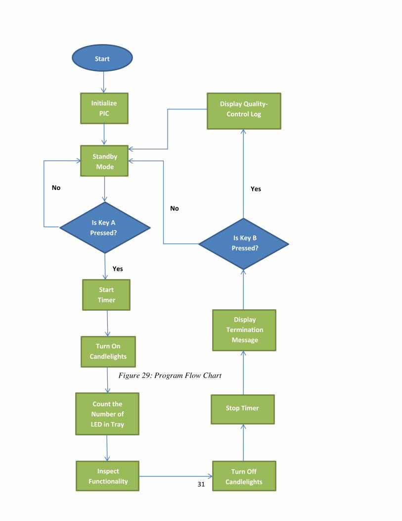
4.3.3 Program Flow Chart
The flow chart is presented in Figure 29 and it displays the actions and decisions that will be made by the microcontroller for one cycle of operation. The program runs in a mostly linear fashion to show a sequential manner.
4.3.4 Emergency Stop
The easily-accessible emergency STOP switch will send a signal to the Master Clear pin to halt all operations in the microcontroller and mechanical systems. It will also cut power to all of the electronic components, minimizing the possible risks caused by both circuitry and mechanical components.
31
Figure 29: Program Flow Chart
Start
Initialize PIC
Standby Mode
Is Key A Pressed?
No
Yes
Start Timer
Turn On Candlelights
Count the Number of LED in Tray
Inspect Functionality
Turn Off Candlelights
Stop Timer
Display Termination
Message
Is Key B Pressed?
No
Display Quality-Control Log
Yes
32
Legend:
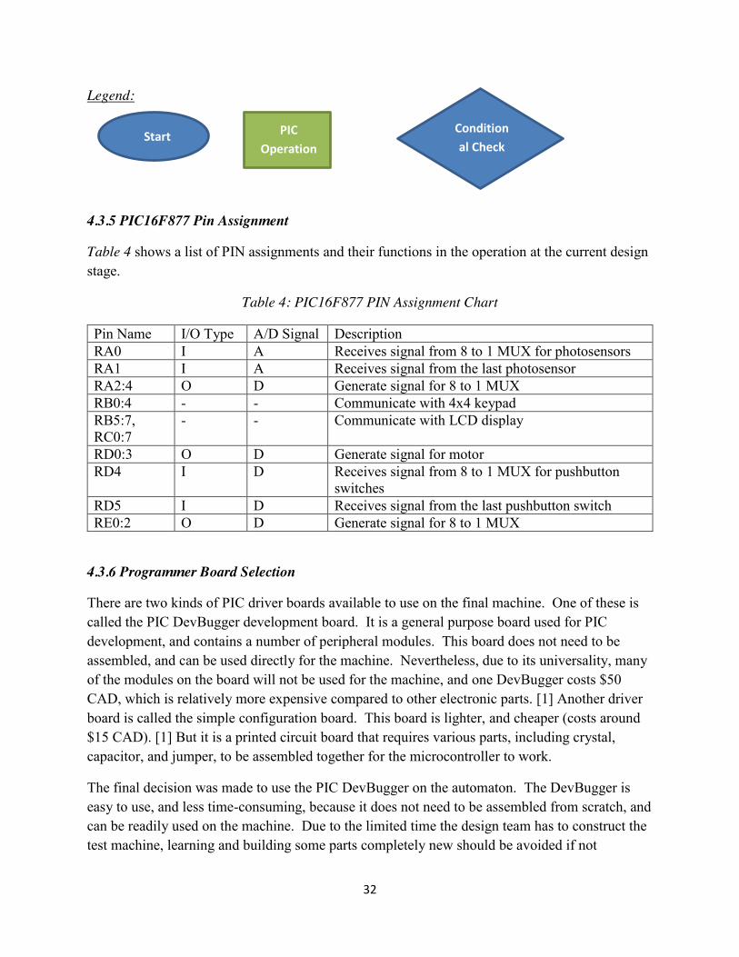
4.3.5 PIC16F877 Pin Assignment
Table 4 shows a list of PIN assignments and their functions in the operation at the current design stage.
Table 4: PIC16F877 PIN Assignment Chart
Pin Name I/O Type A/D Signal Description RA0 I A Receives signal from 8 to 1 MUX for photosensors RA1 I A Receives signal from the last photosensor RA2:4 O D Generate signal for 8 to 1 MUX RB0:4 - - Communicate with 4x4 keypad RB5:7, RC0:7
- - Communicate with LCD display
RD0:3 O D Generate signal for motor RD4 I D Receives signal from 8 to 1 MUX for pushbutton
switches RD5 I D Receives signal from the last pushbutton switch RE0:2 O D Generate signal for 8 to 1 MUX
4.3.6 Programmer Board Selection
There are two kinds of PIC driver boards available to use on the final machine. One of these is called the PIC DevBugger development board. It is a general purpose board used for PIC development, and contains a number of peripheral modules. This board does not need to be assembled, and can be used directly for the machine. Nevertheless, due to its universality, many of the modules on the board will not be used for the machine, and one DevBugger costs $50 CAD, which is relatively more expensive compared to other electronic parts. [1] Another driver board is called the simple configuration board. This board is lighter, and cheaper (costs around $15 CAD). [1] But it is a printed circuit board that requires various parts, including crystal, capacitor, and jumper, to be assembled together for the microcontroller to work.
The final decision was made to use the PIC DevBugger on the automaton. The DevBugger is easy to use, and less time-consuming, because it does not need to be assembled from scratch, and can be readily used on the machine. Due to the limited time the design team has to construct the test machine, learning and building some parts completely new should be avoided if not
Start PIC Operation
Conditional Check

33
necessary since it is better to build a working machine than a malfunction but cheap and light-weight one.
34
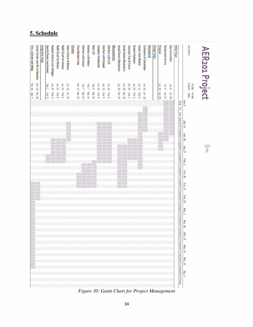
5. Schedule
Figure 30: Gantt Chart for Project Management
35
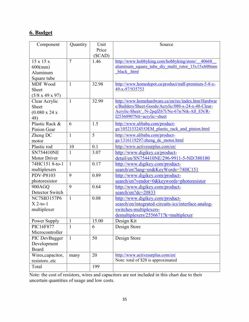
6. Budget
Component Quantity Unit Price
($CAD)
Source
15 x 15 x 600(mm) Aluminum Square tube
7 1.46 http://www.hobbyking.com/hobbyking/store/__40668__aluminum_square_tube_diy_multi_rotor_15x15x600mm_black_.html
MDF Wood Sheet (5/8 x 49 x 97)
1 32.98 http://www.homedepot.ca/product/mdf-premium-5-8-x-49-x-97/935753
Clear Acrylic Sheet (0.080 x 24 x 48)
1 32.99 http://www.homehardware.ca/en/rec/index.htm/Hardware/Builders/Sheet-Goods/Acrylic/080-x-24-x-48-Clear-Acrylic-Sheet/_/N-2pqfZ67l/Ne-67n/Ntk-All_EN/R-I2536090?Ntt=acrylic+sheet
Plastic Rack & Pinion Gear
6 1.5 http://www.alibaba.com/product-gs/1052153245/OEM_plastic_rack_and_pinion.html
Zheng DC motor
1 5 http://www.alibaba.com/product-gs/1316119297/zheng_dc_motor.html
Plastic rod 10 0.1 http://www.activesurplus.com/en/ SN754410NE Motor Driver
1 3.07 http://www.digikey.ca/product-detail/en/SN754410NE/296-9911-5-ND/380180
74HC151 8-to-1 multiplexers
1 0.17 http://www.digikey.com/product-search/en?lang=en&KeyWords=74HC151
PDV-P8103 photoresistor
9 0.89 http://www.digikey.com/product-search/en?vendor=0&keywords=photoresistor
900AGQ Detector Switch
9 0.64 http://www.digikey.com/product-search/en?dc=20833
NC7SB3157P6X 2-to-1 multiplexer
1 0.08 http://www.digikey.com/product-search/en/integrated-circuits-ics/interface-analog-switches-multiplexers-demultiplexers/2556671?k=multiplexer
Power Supply 1 15.00 Design Kit PIC16F877 Microcontroller
1 6 Design Store
PIC DevBugger Development Board
1 50 Design Store
Wires,capacitor,resistors..etc
many 20 http://www.activesurplus.com/en/ Note: total of $20 is approximated
Total 199
Note: the cost of resistors, wires and capacitors are not included in this chart due to their uncertain quantities of usage and low costs.

36
7. Conclusion
An autonomous test machine that is able to inspect the states of functionality of LED candlelights under 90 seconds can reduce the labour of manual testing, provide an efficient control of quality of candlelights, and increase the overall productivity. Therefore, such a machine is desirable to the LED lights manufacturer. This proposal presents an elegant and carefully calculated design of the test machine. This design emphasizes efficiency, robustness, safety, and feasibility: its linear tray enables the machine to inspect all LED candlelights simultaneously and efficiently, it is simple and contains the least number of moving parts for robustness and reliability, and last but not least, the machine’s weight of 4 kg and price of $199 CAD are 33% and 14% below the respective constraints, demonstrating the economy and portability of the solution. One of the possible bottlenecks of the design is the construction of switching mechanism due to the small size of a switch, which requires a high-precision, and meticulous craftsmanship. Another difficulty may be the possible noise in the signals which needs to be filtered and regulated. Nonetheless, these bottlenecks can be solved with dedication and collaboration of the team.
37
Appendix A: Bibliography [1] Emami, Reza. Multidiscipliary Engineering Design. 2014. 2014. Print.
[2] "Switch Test Machine by Using Makeblock." Youtube. N.p.. Web. 29 Jan 2014.
<http://www.youtube.com/watch?v=35s8QObG7bo>.
[3] "Photoelectric Sensors Information." IHS Global Spec. N.p.. Web. 29 Jan 2014.
<http://www.globalspec.com/learnmore/sensors_transducers_detectors/proximity_presence_sens
ing/photoelectric_sensors>.
[4] "LM393 Beam Photoelectric Sensor - Black."MiniInTheBox. N.p.. Web. 29 Jan 2014.
<http://www.miniinthebox.com/lm393-beam-photoelectric-sensor-
black_p643047.html?currency=CAD&litb_from=paid_adwords_shopping&gclid=CKvbjf7Wn7
wCFQsSMwodOWMAJQ>.
[5] "Pushbutton Switches." DigiKey. N.p.. Web. 29 Jan 2014. <http://www.digikey.com/product-
search/en?lang=en&site=us&c=17&f=97>.
[6] "LED Test & Automation Instruments." Chroma. N.p.. Web. 29 Jan 2014.
<http://www.chromaus.com/product_led.html>.
[7] "Model 58158-SC LED Luminaire In-line Test System."Chroma. N.p.. Web. 29 Jan 2014.
<http://www.chromaus.com/product_58158-SC_LED_Luminaires_Inline_Test_System.php>.
[8] "Engineering ToolBox." Engineering ToolBox. N.p.. Web. 29 Jan 2014.
<http://www.engineeringtoolbox.com/>.
[9] "SN754410NE." DigiKey. N.p.. Web. 29 Jan 2014. <http://www.digikey.ca/product-
detail/en/SN754410NE/296-9911-5-ND/380180>.
[10] "900 Series." DigiKey. N.p.. Web. 29 Jan 2014. <http://www.digikey.ca/product-
detail/en/SN754410NE/296-9911-5-ND/380180>.
38
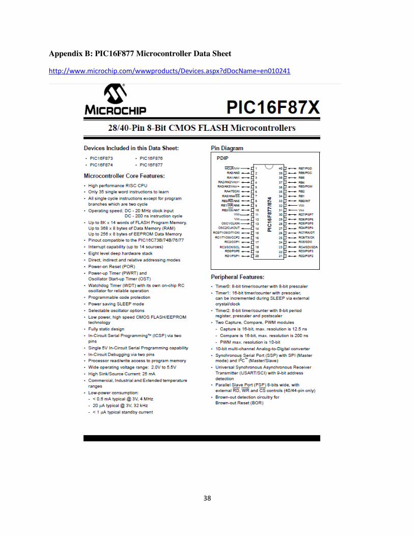
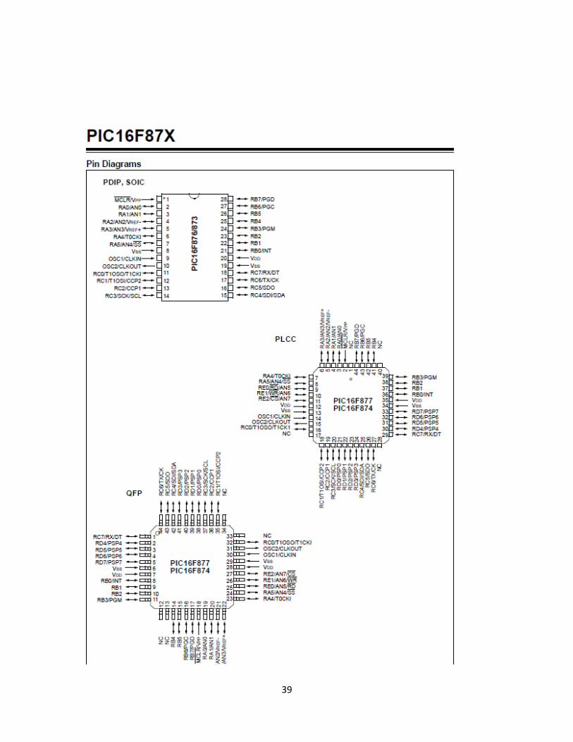
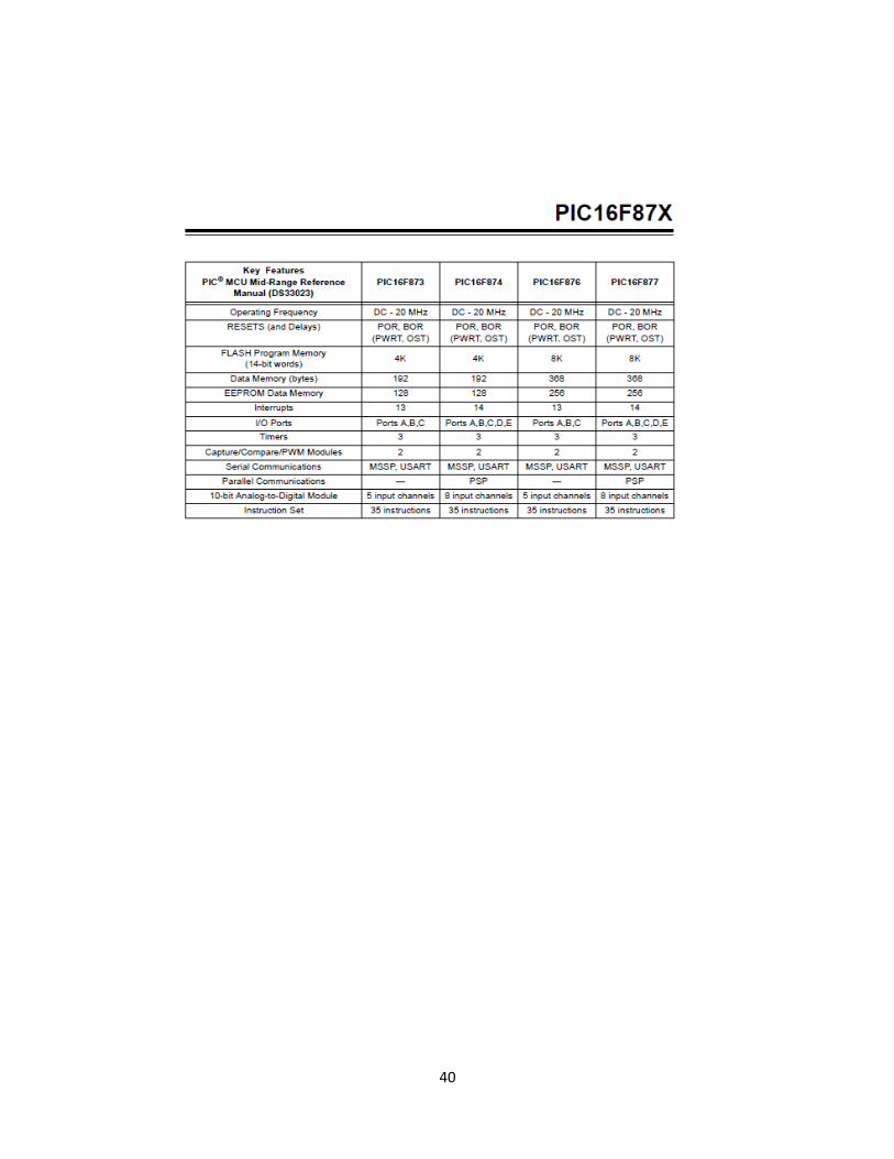
Appendix B: PIC16F877 Microcontroller Data Sheet
http://www.microchip.com/wwwproducts/Devices.aspx?dDocName=en010241
39
40
41
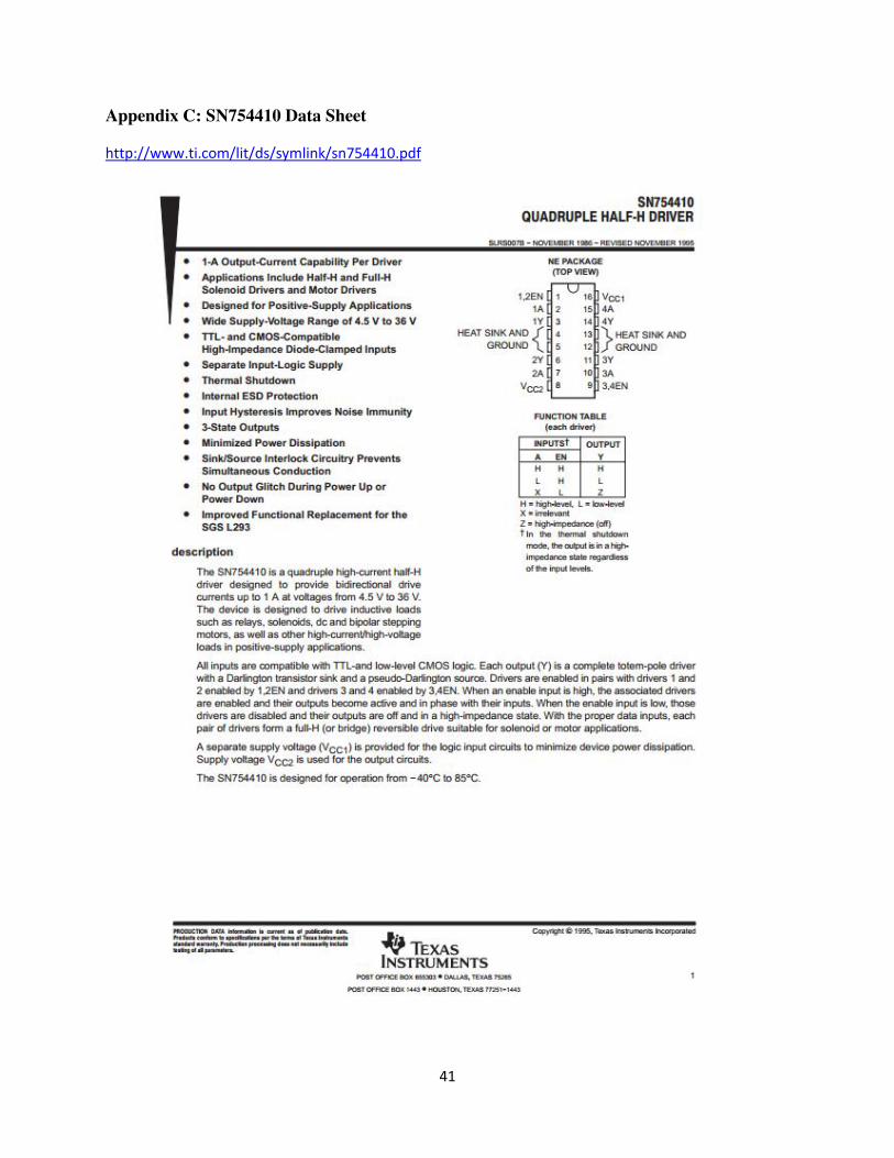
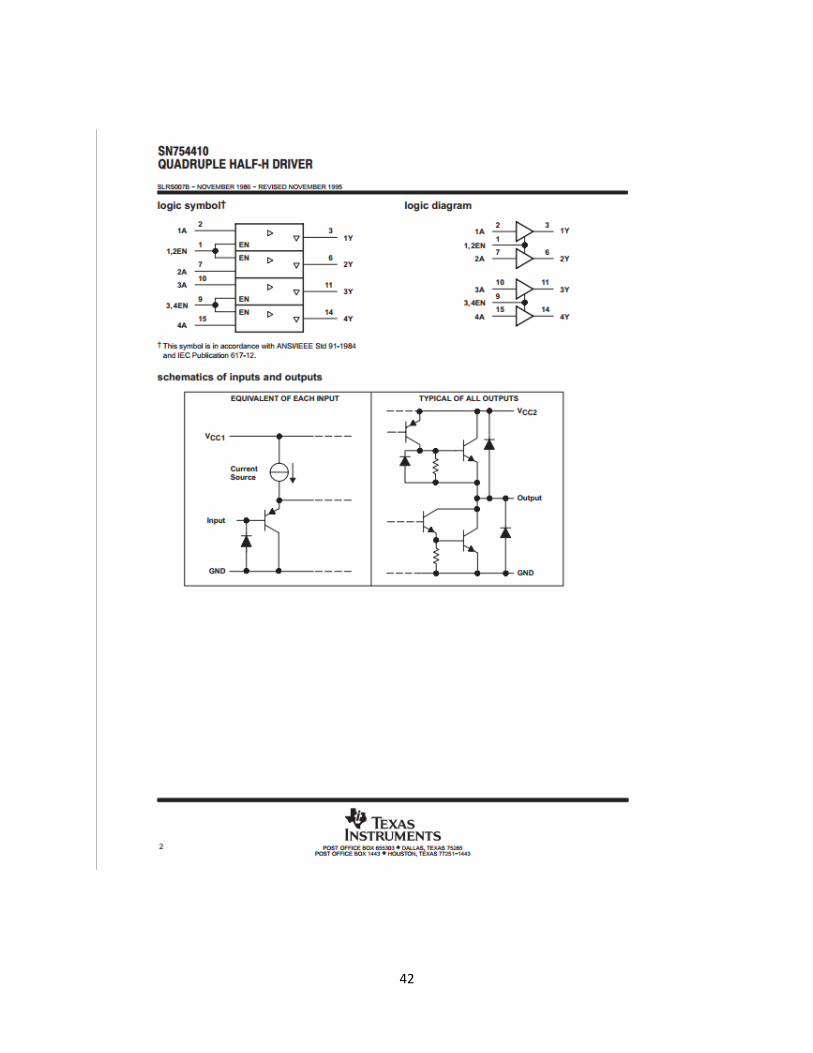
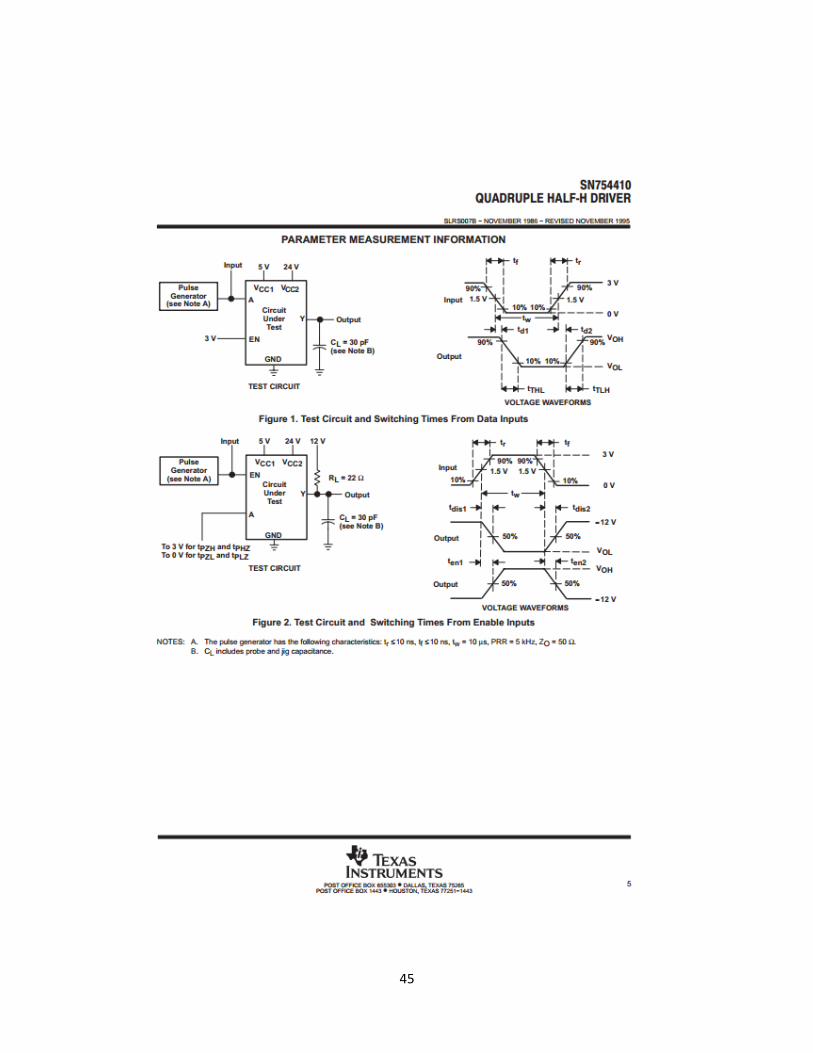
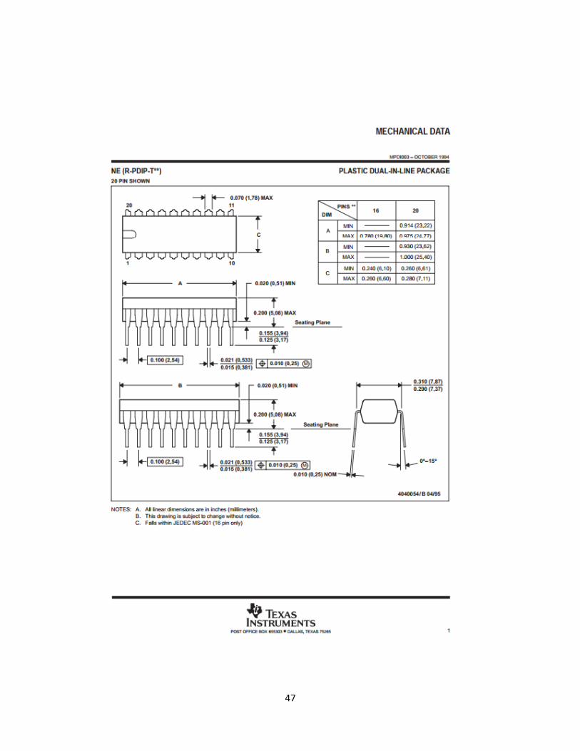
Appendix C: SN754410 Data Sheet
http://www.ti.com/lit/ds/symlink/sn754410.pdf
42
43
44
45
46
47
48
Appendix D: 900 Series Detector Switch Data Sheet
http://www.e-switch.com/product/tabid/96/productid/71/sename/900-series-sub-miniature-smt-detector-switch/default.aspx
49
Appendix E: PDV-P8103 Photoresistor Data Sheet
http://www.advancedphotonix.com/ap_products/pdfs/PDV-P8103.pdf
50
Appendix F: 74HC151 8-to-1 Multiplexers Data Sheet
http://pdf1.alldatasheet.com/datasheet-pdf/view/15539/PHILIPS/74HC151.html
51
52
53
54
55
56
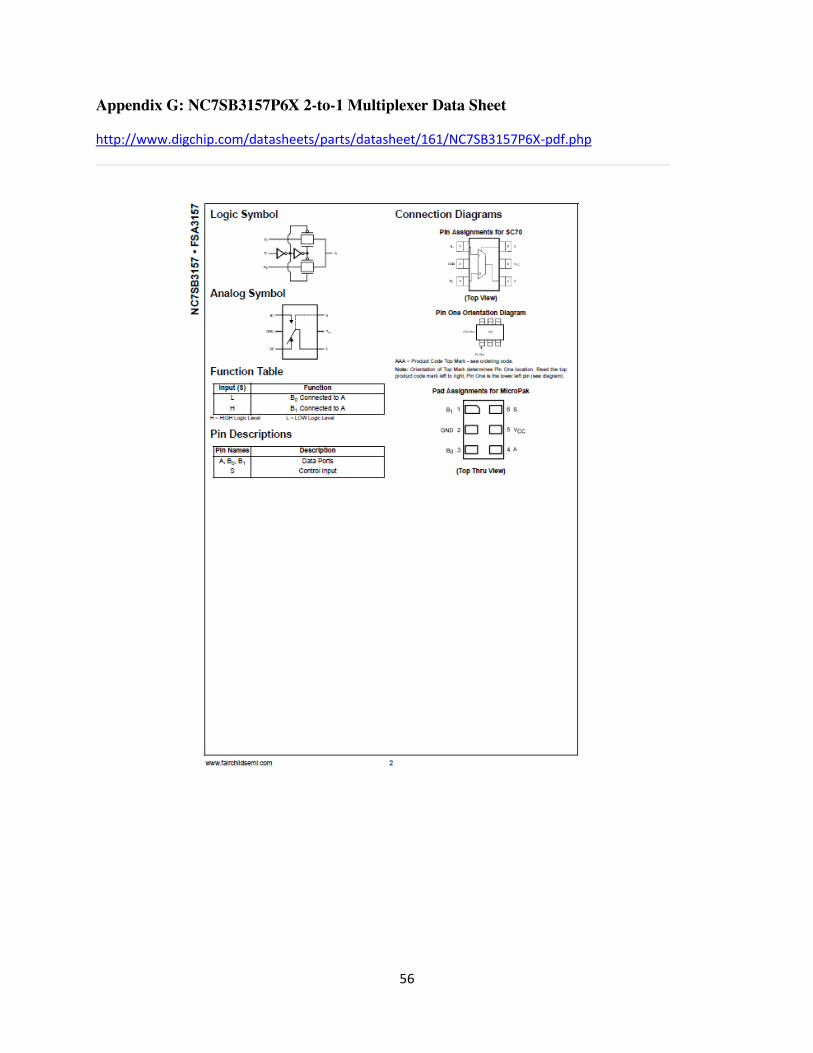
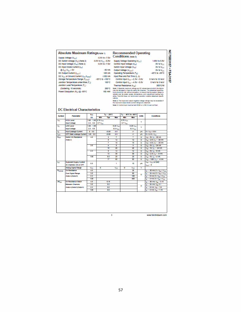
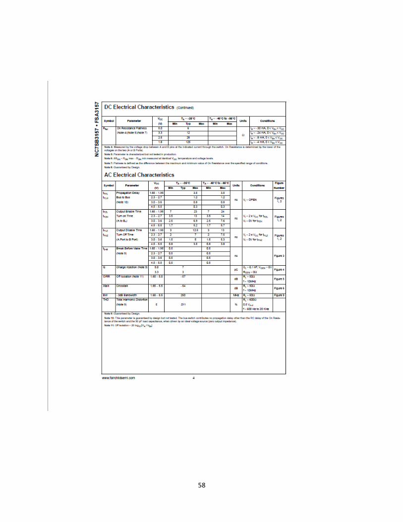
Appendix G: NC7SB3157P6X 2-to-1 Multiplexer Data Sheet
http://www.digchip.com/datasheets/parts/datasheet/161/NC7SB3157P6X-pdf.php
57
58
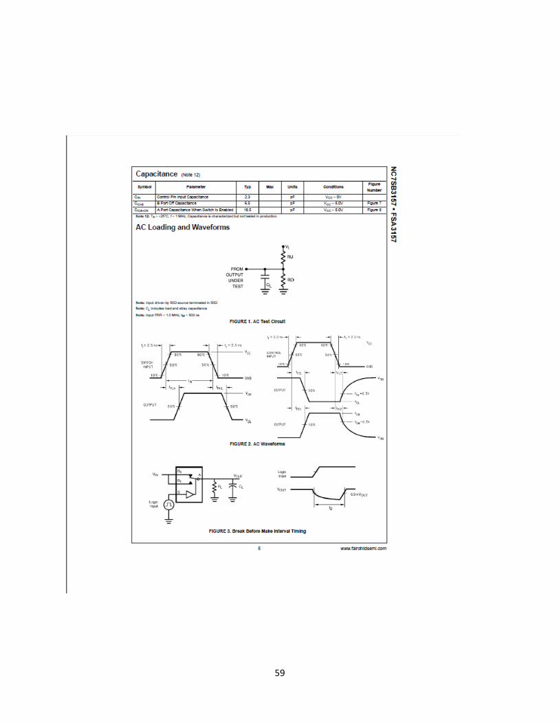
59
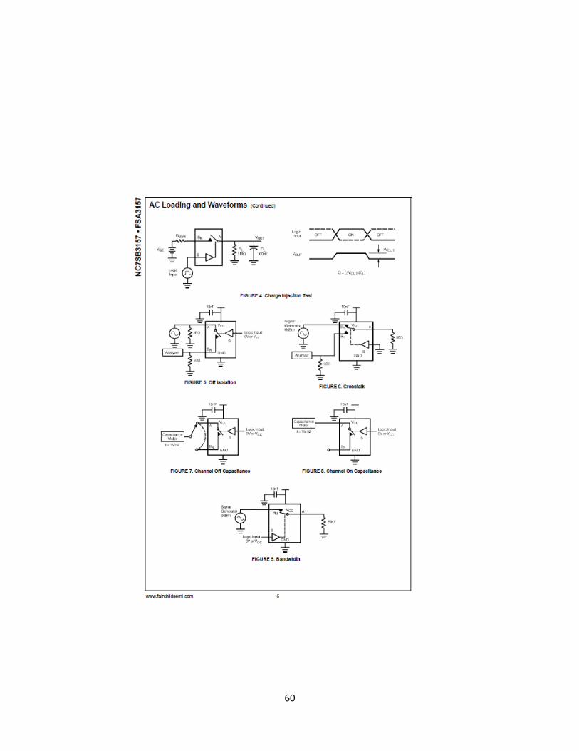
60

61
Appendix H: Material Selection
Material property of Common Material
(http://www.engineeringtoolbox.com/engineering-materials-properties-d_1225.html)

62
Appendix I: Weight Approximation
Estimation of Main Frame
63
Weight Estimation of Lid
64
Weight Estimation of Tray

65
Estimation of Weight of Circuitry and Additional Support
66
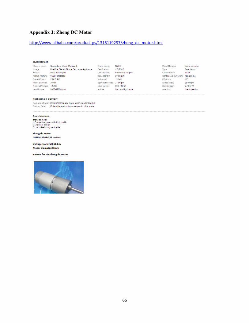
Appendix J: Zheng DC Motor
http://www.alibaba.com/product-gs/1316119297/zheng_dc_motor.html