Embed Size (px)
DESCRIPTION
This project report is also available on:http://kdu-projects.blogspot.com/
Citation preview
Anyone who wish to borrow ideas, or schematics may do so with proper reference. ~ Hussain Ageel Naseer ~ Page 1
Project Report: Frost Alert LED Display
Diploma in Telecommunication and Computer Engineering
Name: Hussain Ageel Naseer
Student #: 51375
Country: Rep. of Maldives
Lecturer: Chan Yun Ghit
Date: 25th June 2010

Anyone who wish to borrow ideas, or schematics may do so with proper reference. ~ Hussain Ageel Naseer ~ Page 2
Content Page
Abstract…………………………………………………………………………….. 3
Acknowledgement………………………………………………………………….. 4
Chapter 1
1.1 Introducation…………………………………………………………… 5
1.2 Objectives of the project……………………………………………….. 6
1.3 List of diagrams………………………………………………………... 6
Chapter 2
2.1 Literature review……………………………………………………….7
2.2 Components and its functions………………………………………….9
Chapter 3
3.1 Methodology…………………………………………………………... 12
3.2 Block diagrams of the Frost Alert Circuit……………………………...15
3.3 Final block diagram of Frost Alert Circuit……………………………..16
3.4 Schematic diagrams…………………………………………………….17
3.5 Combined Circuits………………………………………………………19
Chapter 4
4.1 Results and discussion…………………………………………………..20
Chapter 5
5.1 Conclusion……………………………………………………………….21
5.2 Future development……………………………………………………...22
Chapter 6
6.1 Gantt chart……………………………………………………………….23
6.2 Component Prices……………………………………………………….24
Chapter 7
7.1 Reference…………………………………………………………………25

Anyone who wish to borrow ideas, or schematics may do so with proper reference. ~ Hussain Ageel Naseer ~ Page 3
Abstract
This project, Frost Alert Display, switches on an LED display circuit, keeps the LED display
flashing, when the temperature sensor detects that the temperature has reached freezing point.
This circuit consists of three building blocks. First building block uses an Integrated circuit (IC)
amplifier which responds to change in temperature. This turns on an astable based on a 555
timer. The output of the 555 timer inputs an IC 4017, which runs LED display.

Anyone who wish to borrow ideas, or schematics may do so with proper reference. ~ Hussain Ageel Naseer ~ Page 4
Acknowledgment
In order to finish my project, I have had a lot of help from my fellow class mates. Out
of them, I would like to give special thanks to:
Ahmed Sako
Hsuing Khee
Diresh Kumar
Ashraf Abubakur
Lim Chee Bing
I’ve gained a lot of important information on the projects, and ideas for my project
from them. Also I have got help from them to troubleshoot my circuit.
In addition to them, I would like to thank my supervisor Ms. Chan Yun Ghit. She was
always available most of the time if I had any question regarding my project. And also
her explanations have made me understand more about the circuit. Her being available
most of the time made it very convenient for me to get to her and solve the problems I
had.
I thank all those who helped me with my project.

Anyone who wish to borrow ideas, or schematics may do so with proper reference. ~ Hussain Ageel Naseer ~ Page 5
CHAPTER 1
1.1 Introduction
The Frost Alert Display is used to figure out when the temperature of the environment,
it is in, is at 0˚. The idea of developing this circuit is to be able to take precautions as
soon as you can, so that you can be protected from the cold weather. This can also be
used to make sure if the temperature of the freezer or storage is at 0˚C.
The Frost Alert Display uses a thermistor to detect the temperature surrounded and
alert when it reaches 0˚C by turning on an LED display. Thermistors are resistors
which varies its resistivity as the temperature changes. There are several types of
thermistors and are used for various purposes. Some of its purpose includes: meter
compensation, inrush-current device, and LED control.
LED displays are made up of LEDs. LED, in other words Light Emitting Diodes emits
light when current is passed through it. LED displays are very common. It can be used
to display words, as well as any character. 7-segment LED display is used to display
numbers while dot matrix LED display is used to display letters and numbers.

Anyone who wish to borrow ideas, or schematics may do so with proper reference. ~ Hussain Ageel Naseer ~ Page 6
1.2 Objectives of the Project
Understanding how to turn on an LED display when a thermistor gives out the
resistance equivalent to 0˚C is one of the main objectives of the project. Another
objective was to understand how to make the LEDs display flash when the thermistor’s
detects frost temperature (0˚C).
The main aim of this project is to use all I’ve learned from the past two years to gather
information about the projects: this includes circuit diagrams, and information on the
components. Also the project looks at how well you can edit, and troubleshoot a
circuit.
1.3 List of Diagrams
Temperature Sensor with Operational Amplifier.
IC 555 timer
Frost Alert Circuit
Final Circuit (The three circuits above combined to make a single circuit)
LED Display (Display’s the word ICE)
16-LED running lights
Anyone who wish to borrow ideas, or schematics may do so with proper reference. ~ Hussain Ageel Naseer ~ Page 7
Chapter 2
2.1 Literature Review
A temperature sensor usually works along with another component which monitors the
change of temperature. In today’s World there are different types of sensors and are
being used in different ways in order to create temperature reading circuits. Even
though there are several types of temperature sensors, they all follow one common
thing: all these sensors measures the temperature by sensing the change in physical
characteristics.
The most common seven basic types of temperature sensors includes thermocouples,
resistive temperature devices (RTDs, Thermistors), infrared radiators, bimetallic
devices, liquid expansion devices, molecular change-of-state, and silicon diodes. Each
of these temperature sensors has their own ability in order to measure the temperature.
Thermocouples vary the voltage passing through it with the change in temperature, but
the RTDs vary its resistance (the amount of current passing through it) with the change
in temperature. On the other hand, infrared sensors use infrared radiation to detect the
temperature. Bimetallic sensors and liquid expansion devices have the ability to expand
when it is heated, so the temperature is measured my monitoring the expansion in the
sensor. In molecular change-of-state sensors, the temperature is being recorded when
the material changes its state.

Anyone who wish to borrow ideas, or schematics may do so with proper reference. ~ Hussain Ageel Naseer ~ Page 8
Frost Alert Circuit
This project turns on an LED display when the temperature sensor, a thermistor, senses
the air temperature surrounded it has fallen to 0˚C (meting / freezing point). This
circuit is made up of two building blocks.
Fig.1: Frost Alert Circuit
The first block is an Operating Amplifier, an integrated circuit (IC), which works as a
switch that triggers a 555 timer (IC). The Operational Amplifier in the circuit acts as a
comparator which compares two signals and triggers the output when it detects a better
signal. The Variable resistor is used to set the Op Amp so that when it detects a
specific resistance. The IC 555 timer is used as an astable which keeps on switching
ON and OFF allowing an unstable signal passing through it.

Anyone who wish to borrow ideas, or schematics may do so with proper reference. ~ Hussain Ageel Naseer ~ Page 9
2.2 Components and its function.
Thermistor
A thermistor is a sensor which is used to measure the temperature. Thermistors are
resistors which are sensitive to temperature and vary as the temperature changes. Even
though most of the resistors increase its resistivity with the increase in temperature,
thermistors decrease its resistance as the temperature rises. However, thermistors are
used for simple temperature measurements, because it can only have reasonable output
voltage.

Anyone who wish to borrow ideas, or schematics may do so with proper reference. ~ Hussain Ageel Naseer ~ Page 10
Integrated Circuits (IC):
Integrated circuits are complex circuits which is been fixed in to a tiny chip, and is
made of semiconductor materials.
IC 3140 is an integrated circuit operational amplifier that combines the high voltage
PMOS transistor with the high voltage bipolar transistor on a single chip. This chip has
a high input Impedance, and a very low input current, and performs at a very high
speed. This IC is used widely in different application. Some of the application includes:
sample and hold amplifier, Peak Detector, Active Filter, Comparators, and in
photocurrent instrumentation.
Top view of IC 3140
IC 555 timer can be used in astable and/or monostable mode, depending on the type of
curciut. In astable mode this IC creates continuous series of pulses. Unlike astable, in
monostable mode this IC outputs a single pulse. IC 555 timer can be used as the source
or the sink, and wide range devices are can be used with it.
Top view of a 555 timer

Anyone who wish to borrow ideas, or schematics may do so with proper reference. ~ Hussain Ageel Naseer ~ Page 11
Resistors:
Resistors are components which are used to control the current flowing through a
circuit. To achieve this, it drops the voltage between two points. Resistors completely
reply on the Ohm’s law: which is, V=IR.
There are two basic types of resistors. Those are Fixed-value resistors and variable
resistors. The resistance of fix-value resistors remains the same, while the resistance of
variable resistor can be changed between its resistance range.
Fixed value resistor Variable resistor
Capacitor
Capacitors are used to store electric charge. It is used to smooth the DC voltage passing
through it. In addition they are used in filter circuits as current flows through it as long
as an AC voltage source is connected to it.
Capacitors

Anyone who wish to borrow ideas, or schematics may do so with proper reference. ~ Hussain Ageel Naseer ~ Page 12
Light Emitting Diodes (LED)
Light Emitting Diodes (LEDs) are diodes made of semiconductors, which allows
current to follow only in one direction (forward bias). In LED, two slightly different
materials are kept close together to form a PN junction. LED requires low power, and
has a high efficiency and has a longer life span. Also LEDs can be dimmed and
switched rapidly causing no problems to them, unlike an ordinary bulb.
Some of the applications of the LEDs are Illumination, status indicators, automotive
industries, outdoor lighting and signage.
Anyone who wish to borrow ideas, or schematics may do so with proper reference. ~ Hussain Ageel Naseer ~ Page 13
Chapter 3
3.1 Methodology
Circuit Explanation:
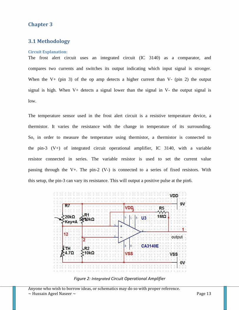
The frost alert circuit uses an integrated circuit (IC 3140) as a comparator, and
compares two currents and switches its output indicating which input signal is stronger.
When the V+ (pin 3) of the op amp detects a higher current than V- (pin 2) the output
signal is high. When V+ detects a signal lower than the signal in V- the output signal is
low.
The temperature sensor used in the frost alert circuit is a resistive temperature device, a
thermistor. It varies the resistance with the change in temperature of its surrounding.
So, in order to measure the temperature using thermistor, a thermistor is connected to
the pin-3 (V+) of integrated circuit operational amplifier, IC 3140, with a variable
resistor connected in series. The variable resistor is used to set the current value
passing through the V+. The pin-2 (V-) is connected to a series of fixed resistors. With
this setup, the pin-3 can vary its resistance. This will output a positive pulse at the pin6.
Figure 2: Integrated Circuit Operational Amplifier

Anyone who wish to borrow ideas, or schematics may do so with proper reference. ~ Hussain Ageel Naseer ~ Page 14
The output signal from the IC Op Amp is then connected to the pin-4 (reset) of another
integrated circuit (IC 555 timer). In the frost alert circuit, it uses a 555 timer in astable
mode. In the astable mode the timer creates a series of pulse in the output. Once the IC
555 timer gets an input signal in the pin-4 (reset) it sends a series of pulse through the
pin-3 (output). An LED is connected to the output and is grounded. The IC 555 timer is
used as a source in the frost alert circuit.
Figure 3: Astable mode based 555 Timer

Anyone who wish to borrow ideas, or schematics may do so with proper reference. ~ Hussain Ageel Naseer ~ Page 15
3.2 Block Diagrams of the Frost Alert Circuit
Input
Figure 4: The block diagram of Frost Alert Circuit
There are three main types of components used in this circuit. A temperature sensor,
integrated circuits, and LED display. IC 3140 acts as a comparator and detects the
change in signal strength from the thermistor, and sends a pulse to the 555 timer. The
555 timer then outputs a series of pulse on its output.
IC 3140
Thermistor
555 Timer
Output

Anyone who wish to borrow ideas, or schematics may do so with proper reference. ~ Hussain Ageel Naseer ~ Page 16
3.3 Final Block Diagram of Frost Alert Display Circuit
Figure 5: Block diagram of frost alert LED display circuit
In the final block diagram, there are two additional blocks: IC 4017 and an LED
display. The output from the 555 timer is connected to IC 4017’s input. The output
signals from IC 4017 is used to run the LED display.
IC 3140
Thermistor
555 Timer
LED Display
IC 4017

Anyone who wish to borrow ideas, or schematics may do so with proper reference. ~ Hussain Ageel Naseer ~ Page 17
3.4 Schematic Diagrams
Schematic Diagram of LED Display
Figure 6: LED Display (LEDs are connected to write ICE)
I have connected all the LEDs, so that when a voltage is passed through, it turns on the
LEDs. All these LEDs are connected to print the word “ICE”. The resistor in the circuit
limits the amount of current passing through the circuit.

Anyone who wish to borrow ideas, or schematics may do so with proper reference. ~ Hussain Ageel Naseer ~ Page 18
Schematic Diagram of a different circuit using IC 4017
Figure 7: 16-LED running lights
At first I finished the frost alert circuit using two ICs. The circuit works perfectly,
turning the LED display ON when the temperature sensor senses freezing temperature.
But the all the LEDs were turned ON or OFF with respect to the comparator. I wanted
LED display to be flashing when the sensor detects the freezing point.
For that reason I searched and found the “16-LED running lights” circuit (figure 7). At
first I tried to input the signal from the 555 timer IC 4017’s input without bringing any
change to the circuit. But for some reasons the LEDs didn’t turn ON.
After reading the datasheet for IC 4017, I took off all the components on the left side of
the schematic diagram, and connected the 555 timer to its CP0 of the IC 4701. As the
555 timer used is astable mode based, the timer keeps on sending a series of pulse
when the temperature sensor detects freezing point. This makes turns the CP0 from
LOW to HIGH, as a result display flashing rapidly.

Anyone who wish to borrow ideas, or schematics may do so with proper reference. ~ Hussain Ageel Naseer ~ Page 19
3.5 Combined Circuits
Figure 8: the final circuit
This diagram shows the three ICs combined together to form a single circuit. In this
circuit, the Op Amp acts as a comparator and detects the change in temperature and
sends an output signal. As the Op Amp is connected to the 555 timer’s reset pin, it
resets the 555 timer resulting in a series of pulse moving out of the 555 timer. The 555
timer output is connected to the CP0 (low to high) leg of the IC 4017. This turn the
LED Display ON and keeps flashing.
Anyone who wish to borrow ideas, or schematics may do so with proper reference. ~ Hussain Ageel Naseer ~ Page 20
Chapter 4
4.1 Results and Discussion
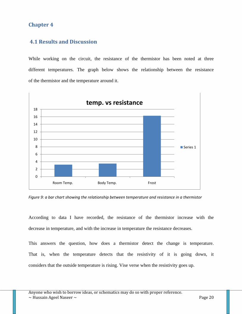
While working on the circuit, the resistance of the thermistor has been noted at three
different temperatures. The graph below shows the relationship between the resistance
of the thermistor and the temperature around it.
Figure 9: a bar chart showing the relationship between temperature and resistance in a thermistor
According to data I have recorded, the resistance of the thermistor increase with the
decrease in temperature, and with the increase in temperature the resistance decreases.
This answers the question, how does a thermistor detect the change is temperature.
That is, when the temperature detects that the resistivity of it is going down, it
considers that the outside temperature is rising. Vise verse when the resistivity goes up.
0
2
4
6
8
10
12
14
16
18
Room Temp. Body Temp. Frost
temp. vs resistance
Series 1

Anyone who wish to borrow ideas, or schematics may do so with proper reference. ~ Hussain Ageel Naseer ~ Page 21
Chapter 5
5.1 Conclusion
Throughout the project, I’ve learned several things about electronic components. I’ve
learned about the different types of fix-resistors and variable resistors. Specially on
integrated circuits, as well as on different types of thermistors. I’ve gained a lot of
knowledge on how the Operational Amplifiers work, and how it can be used as a
comparator. Also I’ve gotten a lot of experiences while working on the projects which
would probably help me in my future.

Anyone who wish to borrow ideas, or schematics may do so with proper reference. ~ Hussain Ageel Naseer ~ Page 22
5.2 Future development
While doing the project, I figured out that this circuit can be used to detect any
temperature within the range of the thermistor used. So I believe this same circuit can
be used not only for frost alert, but also for any other lower temperature.
With a little change of circuit, it can be made to turn on a siren to alert people. I think
this could be a better way to get people’s concentration.
This circuit can also be used as a overheat detector. For an example, this can be used to
detect the car engine temperature

Anyone who wish to borrow ideas, or schematics may do so with proper reference. ~ Hussain Ageel Naseer ~ Page 23
Chapter 6
6.1 Gantt chart:

Anyone who wish to borrow ideas, or schematics may do so with proper reference. ~ Hussain Ageel Naseer ~ Page 24
6.2 Component Prices
Components quantity Prices (RM)
Thermistor (4.7kΩ at 25˚C) 1 1
IC 3140 1 5
IC 555 timer 1 6.5
Resistors 10kΩ, 10kΩ, 1MΩ. 47kΩ, 47kΩ 5 0.50
Variable resistor (22kΩ) 1 0.70
Capacitor ( 0.5µF, 100µF) 2 0.20
IC 4017 1 6
9v Battery 1 5
LEDs (red colour) 25 2.50
Total 27.40

Anyone who wish to borrow ideas, or schematics may do so with proper reference. ~ Hussain Ageel Naseer ~ Page 25
Chapter 7
7.1 Reference:
http://www.wwdmag.com/The-Seven-Basic-Types-of-Temperature-Sensors-article658
http://www.temperatures.com/sensors.html
http://www.facstaff.bucknell.edu/mastascu/eLessonsHTML/Sensors/TempR.html
http://www.ehow.com/about_5039188_uses-thermistor.html
http://www.facstaff.bucknell.edu/mastascu/eLessonsHTML/Sensors/TempR.html
http://www.kpsec.freeuk.com/components/ic.htm
http://www.intersil.com/data/fn/fn957.pdf
http://www.doctronics.co.uk/555.htm
http://www.wisegeek.com/what-are-resistors.htm
http://www.lrc.rpi.edu/programs/nlpip/lightinganswers/led/whatIsAnLED.asp
http://www.bodine.com/products/whatsled.html
http://www.facstaff.bucknell.edu/mastascu/elessonshtml/Interfaces/ConvComp.html
Books:
Teach Yourself: Electronics Malcolm Plant