Embed Size (px)
Citation preview

University of Nebraska-Lincoln NSF REU Supplement Project Report
Project Report
NSF REU Supplement Project: Testbed Development for
AC-MWN: A Novel Architecture for Application-Aware
Cognitive Multihop Wireless Networks
Undergraduate Students: Kossivi Tossou, Trenton Evans
Graduate Students: Feng Ye, Zhihui Shu, Mehrnaz Sharifian Esfahani
PIs: Dr. Yi Qian, Dr. Yaoqing Yang, Dr. Hamid Sharif
Communication Networks & Security Lab
University of Nebraska-Lincoln
Febrary 11, 2014
Abstract
Given the recent upward trend in wireless traffic, capacity demand increases faster than spectral efficiency and
availability. However, it has been well-known that in wireless communications, some of the spectra are
significantly under-utilized. This fact has attracted researchers from academia and industry who are interested
in the next generation of cognitive radio communication systems. Despite the tremendous ongoing efforts on
this research topic, there is a huge gap between the research on cognitive radios and the network applications.
This project exploits a novel wireless networking paradigm called Application-Aware Cognitive Multihop Wireless
Networks (AC-MWN). Besides theoretical analysis, a testbed has been developed in this project to demonstrate
some of the theoretical results. The testbed applications are established using USRP smart radios to apply
cognitive radio technique in various applications, such as file transferring, voice chat and video conference.
Keywords: cognitive radio, multi-hop, testbed
University of Nebraska-Lincoln NSF REU Supplement Project Report
CONTENTS
CHAPTER 1 INTRODUCTION ........................................................................................................ 1
1.1 Background ................................................................................................................ 1
1.2 Equipment .................................................................................................................. 1
1.3 Goals ........................................................................................................................... 2
CHAPTER 2 BASIC FUNCTIONS .................................................................................................... 3
2.1 Equipment Setup ....................................................................................................... 3
2.2 Single-Hop Transmission .......................................................................................... 4
2.2.1 Half-duplex one-way transmission ........................................................................... 4
2.2.3 Full-Duplex Transmission ........................................................................................ 9
2.2.3.1 Adaptive Full-Duplex Transmission .................................................................... 11
2.3 Multi-Hop Transmission ......................................................................................... 12
2.3.1 Simple Transceiver Transmission with Two Smart Radios .................................... 12
2.3.2 Two Radios Multi-Hop (Round-Trip) Transmission .............................................. 14
2.3.3 Three Radios in Multi-Hop (Circular) Transmission ............................................. 16
CHAPTER 3 SENSING ................................................................................................................... 19
3.2 Graphic targeted experiments ................................................................................ 19
3.1.1 Sensing without Primary Users .............................................................................. 19
3.1.2 Sensing with Primary Users ................................................................................... 20
3.1 Intensive Measurements ......................................................................................... 23
4.1 TBD........................................................................................................................... 25
Under Construction ......................................................................................................... 25
CHAPTER 5 CONCLUSION ........................................................................................................ 26
University of Nebraska-Lincoln NSF REU Supplement Project Report
1
CHAPTER 1 INTRODUCTION
1.1 Background
Cognitive radio network (CRN) is a promising technology based on spectrum sensing and opportunistic
spectrum access which can improve the spectrum efficiency of wireless networks [1]. The secondary
users would sense the activities of primary users periodically according to Federal Communications
Commission (FCC) [2]. When a channel is not occupied by a primary user, a secondary user can use
the channel opportunistically after sensing. The major characteristic of cognitive radios is that the
activities of primary users change dynamically and channel availability changes from time to time.
Thus, the secondary users have to efficiently sense the activities of the primary users and make
decisions on which channel to use in the dynamic changing environment. In order to study the
performance of the cognitive radios, we investigate how to develop a testbed and implement algorithms
on the testbed.
Multi-hop cognitive radio networks bring many challenges in testbed design.
First, transmissions on different hops might interfere with each other. Therefore, we investigate how to
implement multi-hop transmission on different channels using USRP2 and USRP N210. Second,
secondary users have to sense the activities of the primary users instantly to get the availability
information of the channels. Thus, we need to develop a practical sensing scheme to find whether the
primary users are working or not. After one available channel is found, the secondary users have to
switch to this channel as soon as possible. Third, the routing and channel allocation schemes have to be
embedded on testbed. We need to implement our proposed routing and allocation schemes on testbed to
show the effectiveness of our proposed algorithms.
To verify the theoretical performance in multi-hop cognitive radio networks, we develop a testbed in
this project for proof-concept. First, we set up the system so that the USRP can be interfaced with GNU
radio. Second, we study several different transmission schemes including single-hop and multi-hop
transmissions based on USRP and smart radios. Then, we investigate how to perform spectrum sensing
using cognitive radios. Finally, we implement our routing and channel allocation schemes on our
testbed.
1.2 Equipment
The testbed consists of three laptops, two USRP2-N210 SDRs, and one USRP2 SDR. Each laptop is
running Ubuntu version 13.10 64-bit operating system with gnuradio software package. The radios
were equipped with firmware and WBX-120 RF daughterboards.

University of Nebraska-Lincoln NSF REU Supplement Project Report
2
1.3 Goals
The main tasks of this REU project include 1) Computer programming and network configuration
using Universal Software Radio Peripheral (USRP) hardware; and 2) Performance evaluation through
experiments and measurements. We will complete the followings:
1. Basic functions
a. Naïve one-way transmission
b. Naïve half-duplex transmission
c. Multi-channel one-way transmission
d. Naïve full-duplex transmission
e. Adaptive one-way transmission
f. Adaptive half-duplex transmission
2. Sensing
a. Sensing if primary user has activity at a given channel
b. Determine a threshold so that false alarm shall be the minimum
3. Cognitive radio technique application
a. Real-time adaptive channel switching
4. Multi-hop applications
a. File transferring, voice chat, and video conference applications using cognitive radio
technique
University of Nebraska-Lincoln NSF REU Supplement Project Report
3
CHAPTER 2 BASIC FUNCTIONS
2.1 Equipment Setup
There are three main things that must be done to setup the system so that the USRP can be
interfaced with GNU radio. These include:
● Download GNU radio software and packages, and once installation is complete use
“gnuradio-companion” to run the graphical programming interface of GNU radio.
● Download required packages for building the UHD driver.
● Configure the network interface by assigning a static IP address to the host computer
Ethernet interface card connected to the USRP2 with $ ifconfig eth0 192.168.10.1 and
finally to test connection with $ ping 192.168.10.2.
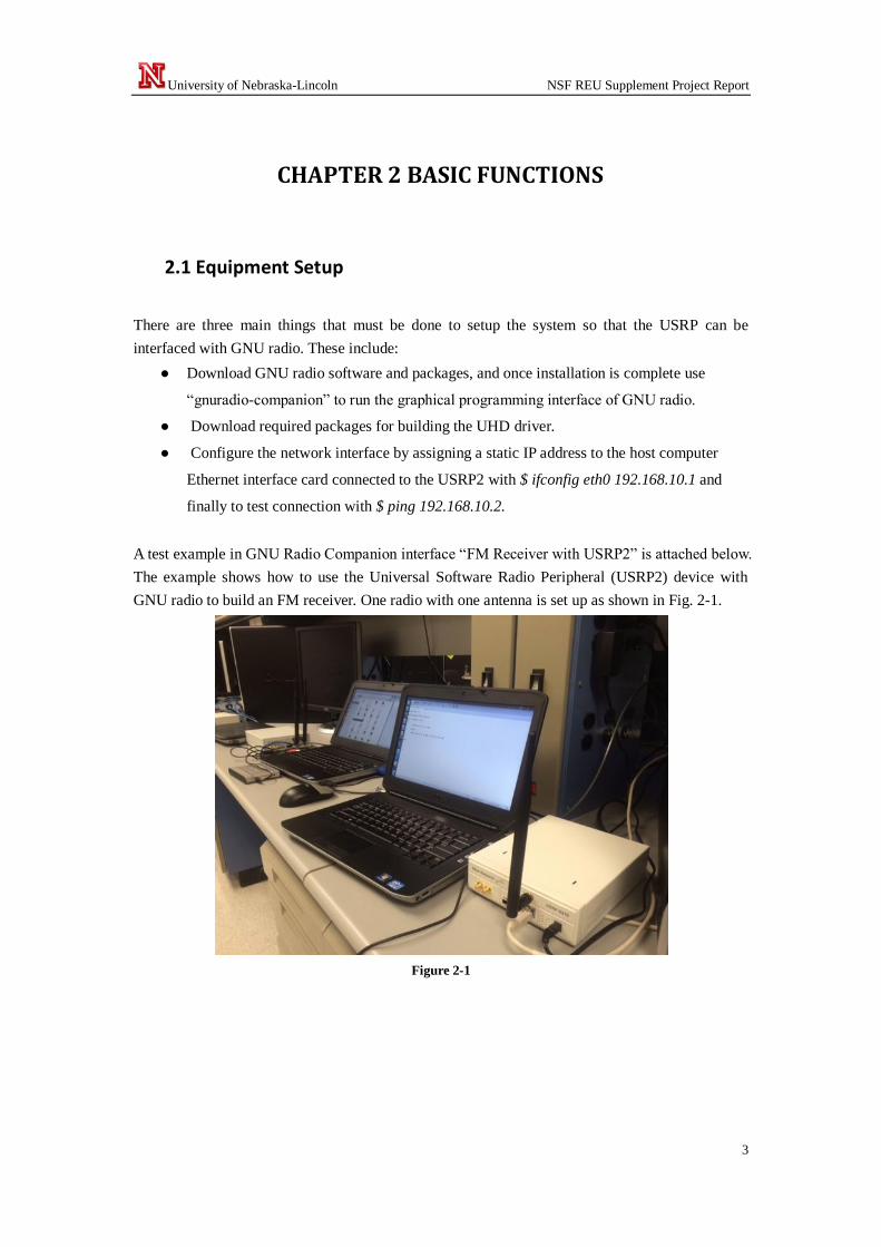
A test example in GNU Radio Companion interface “FM Receiver with USRP2” is attached below.
The example shows how to use the Universal Software Radio Peripheral (USRP2) device with
GNU radio to build an FM receiver. One radio with one antenna is set up as shown in Fig. 2-1.
Figure 2-1

University of Nebraska-Lincoln NSF REU Supplement Project Report
4
Figure 2-2
Output
Figure 2-3
2.2 Single-Hop Transmission
2.2.1 Half-duplex one-way transmission
In this part, we are going to set up one radio as the transmitter and one for receiving, and successfully
send and receive verifiable data. The data is verified at the receiving end when benchmark_rx.py prints
the message and how many successful packets were received.
a. Two smart radios, each equips one antenna. One smart radio is set up for transmitting, the other for
receiving, single dedicated channel (e.g., FM radio)
We successfully achieved this milestone by transmitting and receiving based on frequencies, by
packages transfer and data transfer. We used benchmark code under our gnuradio folder to accomplish
these tasks.
● First we composed a .odb file with the sentence “It is a beautiful day”) . The .odb is
associated with 'OpenOffice/StarOffice in Ubuntu (It is like notepad in Windows system)
which we saved in the same folder of our benchmark code
( usr/local/share/gnuradio/examples/digital/ofdm).

University of Nebraska-Lincoln NSF REU Supplement Project Report
5
Then we modified the benchmark_tx.py and benchmark_rx.py code to conform as transmitting and
receiving a data file. And finally we ran the scripts below from the transmission terminal and
reception terminal:
./benchmark_tx.py -f 900M - - from-file=nice.odb
./benchmark_rx.py -f 900M
The settings and results are shown below:
Setting: two radios with one antenna each
Figure 2-4
Output at the transmitter radio without sending file
Figure 2-5
University of Nebraska-Lincoln NSF REU Supplement Project Report
6
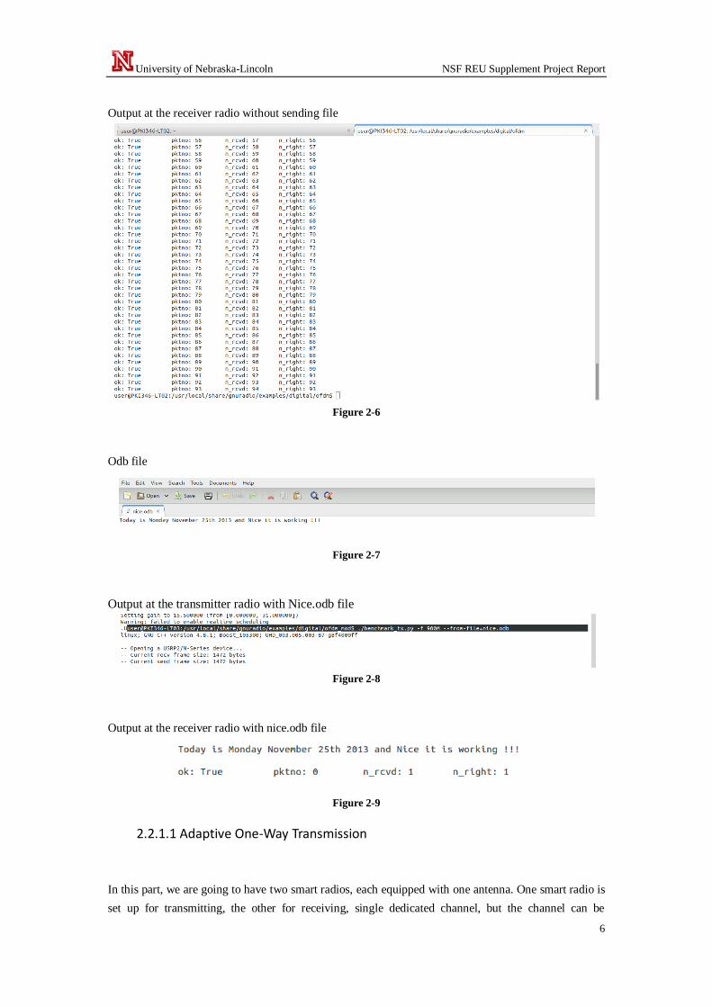
Output at the receiver radio without sending file
Figure 2-6
Odb file
Figure 2-7
Output at the transmitter radio with Nice.odb file
Figure 2-8
Output at the receiver radio with nice.odb file
Figure 2-9
2.2.1.1 Adaptive One-Way Transmission
In this part, we are going to have two smart radios, each equipped with one antenna. One smart radio is
set up for transmitting, the other for receiving, single dedicated channel, but the channel can be

University of Nebraska-Lincoln NSF REU Supplement Project Report
7
switched according to some algorithm automatically (e.g., FM radio, but will change channel once
every 10 seconds)
Setting: two radios with two antennas
Figure 2-10
GRC companion for Radio 1: Receiving blocks
Figure 2-11
We ran the bash script and we can see that each radio was taking turn to transmit and receive
automatically. We are working on the correct synchronization and time delay to perfect this half duplex
transmission. Bash script at the transmitter
Figure 2-13
Bash script at the receiver

University of Nebraska-Lincoln NSF REU Supplement Project Report
8
Figure 2-14
Output
Figure 2-15
Setting: two radios with one antenna each
Figure 2-16
Then, we are going to have two radios with two antennas each. Radio 1 will transmit using the TX/RX
antenna while Radio 2 will receive on the same channel using the RX2 antenna. Next, Radio 2 will be
set up to transmit on a different channel using its TX/RX antenna while Radio 1 receives on the same
channel using the RX2 antenna.
First, we test one-way multi-channel transmission. The settings include two smart radios, each equips
two antennas. One smart radio is set up for transmitting; the other for receiving, transmission is set up
using two channels through two antennas simultaneously.
Setting: two radios with two antennas

University of Nebraska-Lincoln NSF REU Supplement Project Report
9
Figure 2-17
We repeated the same design and procedure with the Naïve one-way transmission but with two
antennas.
2.2.3 Full-Duplex Transmission
In this part, we are going to achieve full-duplex transmission with two smart radios, each equips two
antennas. One antenna of a smart radio is set up for transmitting; the other antenna of this smart radio is
set up for receiving. Two-way transmission should be achieved.
We also worked on IO file management between the transmission and receiving radios, and then added
an acknowledgement time when either receiver or transmitter received or transmitted in the proper
folder designed in advance by using the benchmark scripts
The objective was to save the data in text file after receiving in from the transmitting radio; then to
resend the same data in the text file to the first radio with acknowledgement time and date of reception.
We accomplished this by adding in our original script:
● Transmission script: ( needed to be added to the benchmark_tx script)
def read_dir():
If os.path.exist(“”)
file = open(‘’,’’) - Opens a file on the specified path with read/write access.
ts = str(datetime.datetime.now()) – print the actual time
file.write(ts)
global ack
file.close()
● Reception script: (needed to be added in the benchmark_rx script)
def ensure_dir():
If not os.path.exist(“”)
Os.mkdir(“”)
file = open(‘’,’’) - Opens a file on the specified path with read/write access.
gobal x
University of Nebraska-Lincoln NSF REU Supplement Project Report
10
x = payload -- - data to be received
file.write(x)-- - save data in the specified path with read/write access
file.close()
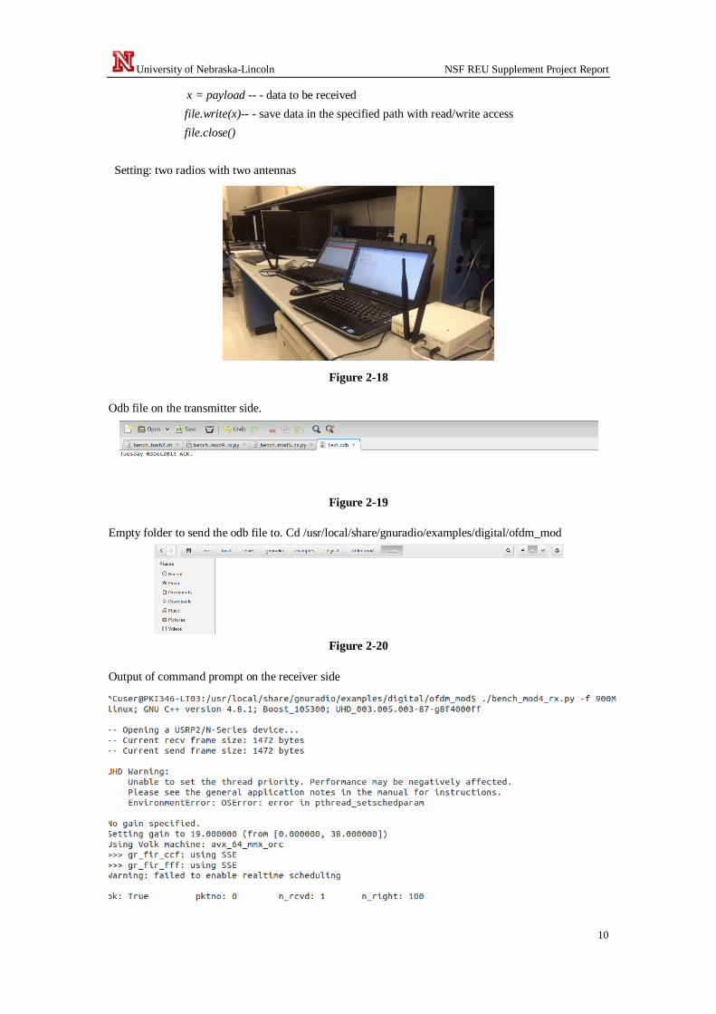
Setting: two radios with two antennas
Figure 2-18
Odb file on the transmitter side.
Figure 2-19
Empty folder to send the odb file to. Cd /usr/local/share/gnuradio/examples/digital/ofdm_mod
Figure 2-20
Output of command prompt on the receiver side

University of Nebraska-Lincoln NSF REU Supplement Project Report
11
Output after creating the file to. Cd /usr/local/share/gnuradio/examples/digital/ofdm_mod
Figure 2-21
File with datetime acknowledgement.
Figure 2-22
2.2.3.1 Adaptive Full-Duplex Transmission
In this part, we are going to set up hardware is Similar to 5, but we use gnuradio-companion flow chart
software to utilize the built in threading capabilities.
The settings are similar to 5 but the flow charts shown in Figures 2-11 & 2-12 are combined to make
one flow chart to create a transceiver.
Figure 2-23
Output is
Figure 2-24

University of Nebraska-Lincoln NSF REU Supplement Project Report
12
2.3 Multi-Hop Transmission
2.3.1 Simple Transceiver Transmission with Two Smart Radios
In this part, we are going to use two radios setup with the grc file shown in Figure 2-26 and both
channels are observed with the FFT GUI as shown in Figure 2-27.
The settings are shown below:
The block below was designed in gnuradio companion. It consisted of two separated blocks, one for the
transmission and the other for the receiving. The grc components used for this design are:
One radio set up with one laptop
Figure 2-25
Transmission blocks:
Audio Source, NBFM Transmit, Multiply Const, UHD: USRP Sink
Receiving blocks:
UHD: USRP Source, Low Pass filter, NBFM Receive, Audio Sink and WX GUI FFT Sink
Figure 2-26

University of Nebraska-Lincoln NSF REU Supplement Project Report
13
Finally we generated flow graph and then executed, and we had the output FFT plot of Transceiver
block design with 1 MHz bandwidth as shown in Fig. 2-27.
Figure 2-27
Figure 2-28
The output FFT plot of Transceiver block design with 10 MHz bandwidth at 900 MHz is shown in Fig.
2-28. The output FFT plot of Transceiver block design with 10 MHz bandwidth at 920 MHz is shown
in Fig. 2-29.

University of Nebraska-Lincoln NSF REU Supplement Project Report
14
Figure 2-29
2.3.2 Two Radios Multi-Hop (Round-Trip) Transmission
In this part, we are going to use two radios, one with our regular transceiver grc file and another with a
relay file. The relay is set up to receive on one frequency and immediately transmit the data on another
frequency. Therefore, the data is transmitted from Radio 1 and channel A, received by Radio 2 on
channel A then transmitted by Radio 2 on channel B, and finally, received by Radio 1 on channel B.
In this section we designed a full duplex transmission with data exchange between two radios. We used
specific blocks as OFDM, File Source and File sink. The full duplex was tested and it worked perfectly
by exchanging data from the receiving radio to the transmission radio in a folder we pre-created for the
circumstance.
Setting:
Two radios set up with one radio
Figure 2-30
● The first radio sent a data information with two sets of blocks in GRC companion (a receiver
and transmitter blocs).
● The second received the data sent, saved it and resent it to the first radio and this is loop.
Radio 1:
Transmission frequency: 950MHz
Receiving frequency: 900MHz

University of Nebraska-Lincoln NSF REU Supplement Project Report
15
Figure 2-31
File source:
We created an ofdm_tx folder with the sentence “PKI OPEN HOUSE…” on directory
/home/user/ofdm_tx. File sink (where the file is received after the second radio resent what it received.)
/home/user/ofdm_rx.
Output:
Figure 2-32
Radio 2:
Transmission frequency: 900 MHz
Receiving frequency: 950MHz
Figure 2-33

University of Nebraska-Lincoln NSF REU Supplement Project Report
16
Output:
Figure 2-34
2.3.3 Three Radios in Multi-Hop (Circular) Transmission
In this part, we are going to use the same design for the simple loop transmission between 2 radios. The
first radio was set on the frequency of 950 MHz to transmit and 900 MHz to receive. The second radio
receives at 950 MHz but retransmits the same information at 830 MHz and the third radio receives at
the frequency of 830 MHz but retransmits the same data to the first radio on the frequency of 900MHz.
The design was tested and it worked successfully.
Setting:
Three radios set up with one radio
Figure 2-35
Radio 1:
Transmission frequency: 950MHz
Receiving frequency: 900MHz
Radio 2:

University of Nebraska-Lincoln NSF REU Supplement Project Report
17
Transmission frequency: 830MHz
Receiving frequency: 950MHz
Radio3:
Transmission frequency: 900 MHz
Receiving frequency: 830MHz
Radio 3: Design Template and output:
Figure 2-36
Output:
Figure 2-37
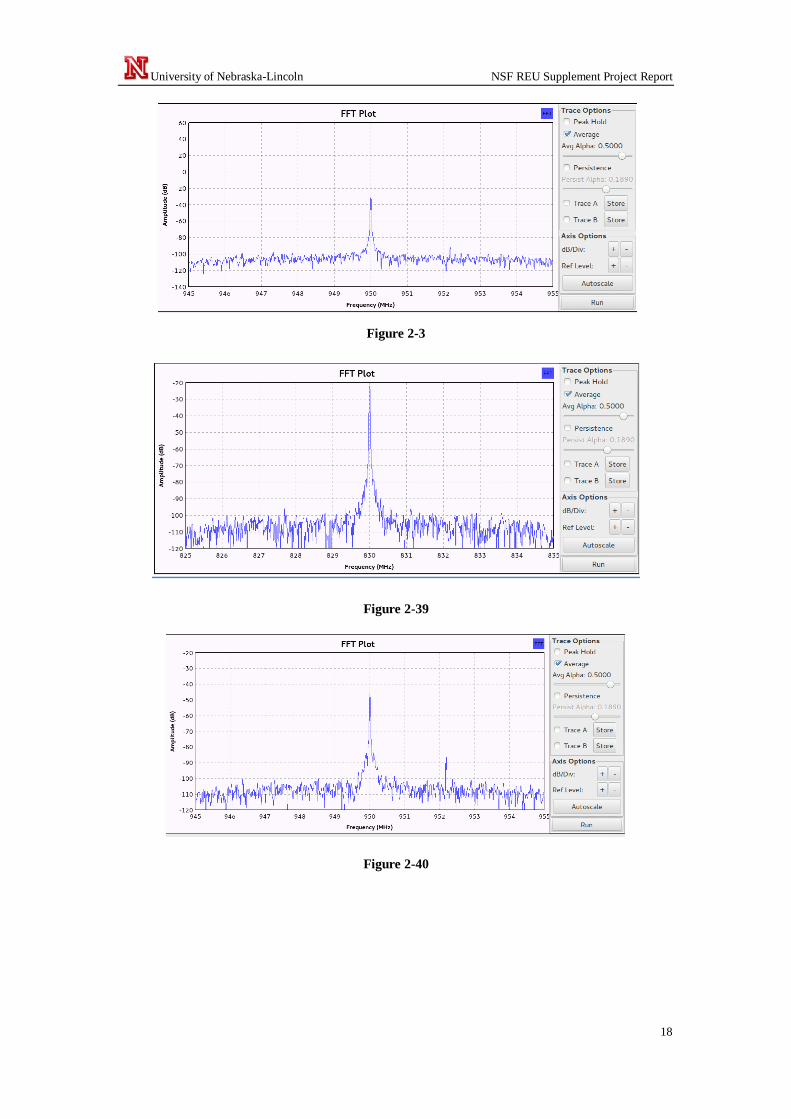
FFT plot of Transceiver block design with 10MHz bandwidth at 950MHz center freq is shown in Fig.
2-38. The FFT plot of Transceiver block design with 10MHz bandwidth at 830MHz center freq is
shown in Fig. 2-39.
University of Nebraska-Lincoln NSF REU Supplement Project Report
18
Figure 2-3
Figure 2-39
Figure 2-40
University of Nebraska-Lincoln NSF REU Supplement Project Report
19
CHAPTER 3 SENSING
3.1 Graphic targeted experiments
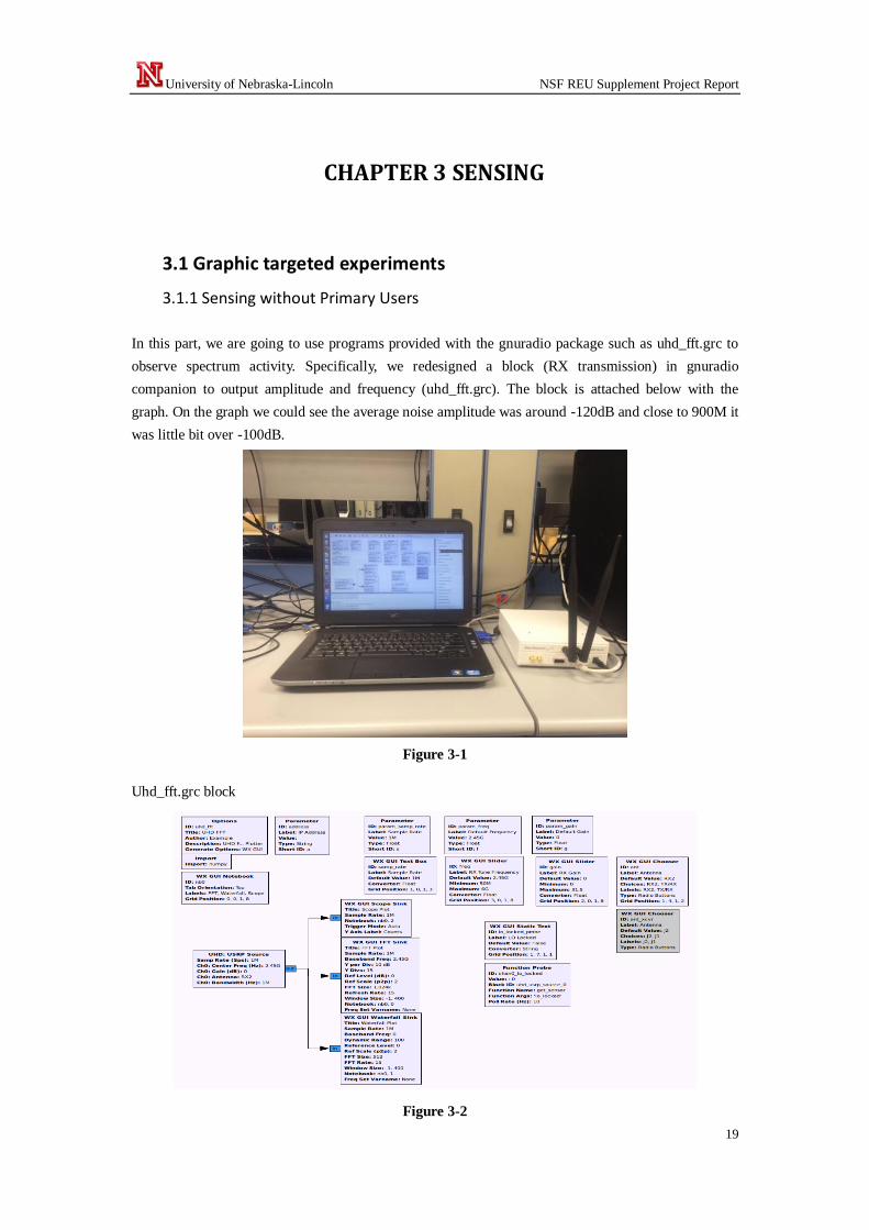
3.1.1 Sensing without Primary Users
In this part, we are going to use programs provided with the gnuradio package such as uhd_fft.grc to
observe spectrum activity. Specifically, we redesigned a block (RX transmission) in gnuradio
companion to output amplitude and frequency (uhd_fft.grc). The block is attached below with the
graph. On the graph we could see the average noise amplitude was around -120dB and close to 900M it
was little bit over -100dB.
Figure 3-1
Uhd_fft.grc block
Figure 3-2

University of Nebraska-Lincoln NSF REU Supplement Project Report
20
Output at 900MHz with 10MHz bandwidth
Figure 3-3
Output at 925MHz with 10MHz bandwidth
Figure 3-4
3.1.2 Sensing with Primary Users
In this part, we are going to include another radio to transmit at different frequencies to observe
changes in noise floor power received. We continue to work on the frequency sensing milestone but
this time we used a transmission block design to send a signal at 900M. (Pictures below, since we
could not take a screen shot with the cursor on the maximum amplitude. The picture is when no signal
was sent to the uhd_fft design on the radio 1. The 2nd and third pictures are when the transmission
signal is run on the second radio at 900M. The amplitude when no signal is available was at -93.75
dBm, and it was -67 dBm when a signal was detected with -34 dBm as pick amplitude.
The output (attached) below shows that our noise_floor_db average was -102 dBm around 900M the
center frequency at which the transmission radio is sending signal. At 899 M the average noise_floor
was -112 dBm and at 901M the noise_floor was at -114 dBm.
Setting:
Set two radios with GRC companion, one to transmit at 900M the other to run the uhd_fft.grc to sense

University of Nebraska-Lincoln NSF REU Supplement Project Report
21
Figure 3-6
Uhd_fft block
.
Figure 3-7
Transceiver block to transmit at 900M
Figure 3-8

University of Nebraska-Lincoln NSF REU Supplement Project Report
22
Output:
Before transmission
Figure 3-9
After
Figure 3-10
A closer look is shown in Fig. 3-11
Figure 3-11
University of Nebraska-Lincoln NSF REU Supplement Project Report
23
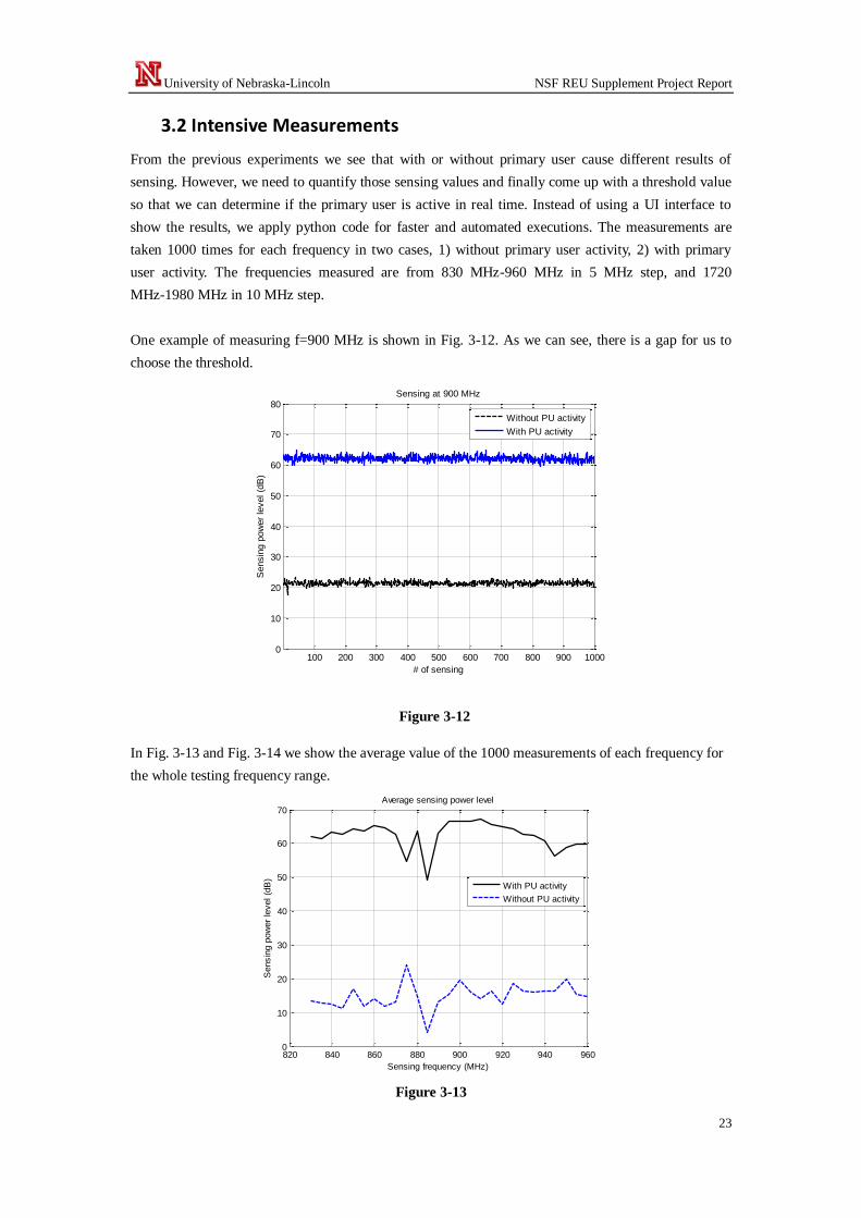
3.2 Intensive Measurements
From the previous experiments we see that with or without primary user cause different results of
sensing. However, we need to quantify those sensing values and finally come up with a threshold value
so that we can determine if the primary user is active in real time. Instead of using a UI interface to
show the results, we apply python code for faster and automated executions. The measurements are
taken 1000 times for each frequency in two cases, 1) without primary user activity, 2) with primary
user activity. The frequencies measured are from 830 MHz-960 MHz in 5 MHz step, and 1720
MHz-1980 MHz in 10 MHz step.
One example of measuring f=900 MHz is shown in Fig. 3-12. As we can see, there is a gap for us to
choose the threshold.
Figure 3-12
In Fig. 3-13 and Fig. 3-14 we show the average value of the 1000 measurements of each frequency for
the whole testing frequency range.
Figure 3-13
100 200 300 400 500 600 700 800 900 10000
10
20
30
40
50
60
70
80
# of sensing
Sensin
g p
ow
er
level (d
B)
Sensing at 900 MHz
Without PU activity
With PU activity
820 840 860 880 900 920 940 9600
10
20
30
40
50
60
70
Sensing frequency (MHz)
Sensin
g p
ow
er
level (d
B)
Average sensing power level
With PU activity
Without PU activity

University of Nebraska-Lincoln NSF REU Supplement Project Report
24
It is shown in Fig. 3-14 that at f=1960 MHz there is a steep down, we ran the same testing for
another 4000 times and its maximum value was still below 10 dB (above the noise level). We will
do more evaluations about this frequency however we conclude it as a hardware issue by now.
Figure 3-14
1700 1750 1800 1850 1900 1950 20005
10
15
20
25
30
35
40
45
50
Sensing frequency (MHz)
Sensin
g p
ow
er
level (d
B)
Average sensing power level
With PU activity
Without PU activity

University of Nebraska-Lincoln NSF REU Supplement Project Report
25
CHAPTER 4 MWCRN APPLICATIONS
4.1 TBD
Under Construction

University of Nebraska-Lincoln NSF REU Supplement Project Report
26
CHAPTER 5 CONCLUSION
Under construction
University of Nebraska-Lincoln NSF REU Supplement Project Report
27
References
[1] J. Mitola. III, “Cognitive Radio for Flexible Mobile Multimedia communications,” IEEE 1999
Mobile Multimedia Conference (MoMuC), pp. 3-10, Nov. 1999.
[2] FCC, ET Docket No. 03-222 Notice of proposed rule making and order, Dec. 2003.