Embed Size (px)
Citation preview
Sewer System Evaluation Survey 8/7/2009
TM No. 4 – Lift Station Monitoring Page 1 of 9
Technical Memorandum Technical Memorandum Technical Memorandum Technical Memorandum 4444
PROJECT: SEWER SYSTEM EVALUATION SURVEY – NAVAL STATION GREAT LAKES
DATE: 7-AUGUST-2009
SUBJECT: TASK 800 – LIFT STATION MONITORING
PROJECT NO: N40083-08-D-0065
Introduction
HDR Engineering, Inc. (HDR) was contracted by NAVFAC MW (NAVFAC) to perform a Sewer System Evaluation Survey (SSES) under Delivery Order 0001 of Contract N40083-08-D-0065. Under Task 800, HDR was asked to conduct an operational assessment for Lift Stations A, C, and F located on Naval Station Great Lakes. Lift Stations A and C are wet well-dry pit stations while Lift Station F is a submersible lift station. HDR’s scope under this task involves determining the “as-is” average daily flow pumped by each station and then make recommendations for the design sizing of the stations utilizing submersible pumps in new wet wells as applicable. A budgetary scope of work and estimate of probable construction cost will also be included. During the flow monitoring activities conducted by HDR in September through December 2008, the influent flow to Lift Stations A, C, and F were recorded. This data and operational summaries for each station were presented in a SSES Interim Report submitted to NAVFAC in April 2009. Utilizing the data collected during flow monitoring and information on the service area for the stations provided by NAVFAC, this memorandum presents design criteria recommendations for replacing the existing pumps and wet well in Lift Station F and converting Lift Stations A and C to submersible pumping stations.
Service Area Descriptions and Existing Pump Station Information
Lift Station A
Lift Station A (LS A), located in Area E, Basin 14, receives wastewater from a small residential housing area built in the 1960s. The current lift station configuration is a wet well-dry pit system with two dry pit centrifugal Fairbanks Morse pumps. Information on

Sewer System Evaluation Survey 8/7/2009
TM No. 4 – Lift Station Monitoring Page 2 of 9
the pumps currently installed in LS A was obtained from the station O&M Manual provided by NAVFAC and is shown in Table 1 below. A pump curve for these pumps was also available and was plotted on the system curve so that the station’s current pumping capacity could be estimated. The system curve and the existing pump curve are presented in Appendix A.
Table 1. Lift Station A Existing Pump Information Provided by NAVFAC
2 Fairbanks Morse Pumps
Model 5430
Size (in.) 4
Impeller Dia. (in.) 8
Design flow (gpm) 200
Design TDH (ft) 24
RPM 1180
HP 3
Phase 3
Volts 230
Hz 60
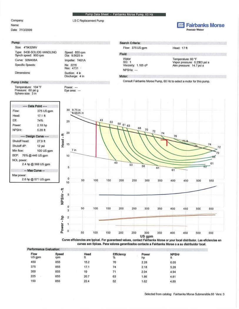
Lift Station C
Lift Station C (LS C) is located in Area E Basin 14 and receives wastewater from a laundry facility and three warehouses. The laundry facility is a converted warehouse and did not exist when the pump station was constructed. During the manhole inspection field work, HDR’s site representative noted that the first manhole upstream of the LS C wet well was surcharged. Also, the inspections of the two 10-inch gravity lines upstream of the station were abandoned due to high water levels in the pipes. These observations suggest that either the floats controlling the pumps are set such that surcharging of the influent line is expected, the existing pumps are not pumping at the expected rate due to a clog or other maintenance issue, or the existing pumps do have the required pumping capacity to keep up with the influent flow. The latter scenario is unlikely due to the normal to high number of pump starts recorded during the flow monitoring period. The current lift station configuration is a wet well-dry pit system with two dry pit centrifugal pumps. Information provided by NAVFAC on the existing Allis-Chalmers pumps installed in LS C is shown in Table 2 below. The Allis-Chalmers pump representative in the Chicago area was contacted to obtain a curve for these pumps so that the station’s current pumping capacity could be estimated using the system curves. It should be noted that the curve provided by the manufacturer is for a 4 x 4 x 12 LC pump which is different from the size given by NAVFAC (6 x 4 x 18 LC). However, the serial number matched the size for the curve provided and the manufacturer stated that a 6 x 4 x 18 LC pump did not exist. The manufacturer further explained that the six in the first number indicates that a reducer was installed on the pump. The pump curve provided by the pump representative was plotted on the system curve to estimate the current capacity

Sewer System Evaluation Survey 8/7/2009
TM No. 4 – Lift Station Monitoring Page 3 of 9
of LS C. The system curve and the Allis-Chalmers pump curve are presented in Appendix B.
Table 2. Lift Station C Existing Pump Information Provided by NAVFAC
2 Allis-Chalmers Pumps
Type NSWV
Size 6 x 4 x 18 LC*
Serial # 83138074-02-1
Frame F7-M2
Impeller Dia. (in.) 9.25
GPM 350
HDFT 15
RPM 870
Pump Motor MOD
5K3215QNL8JA6A
Manufacturer General Electric
Serial # SJP4192MK01A
HP 3
Phase 3
Volts 230
Hz 60
* Manufacturer stated that the serial number given matched a 4 x 4 x 12 LC pump size and provided the curve for it.
Lift Station F
Lift Station F (LS F) is located in Area B Basin 5, receiving wastewater from four buildings in the Camp Moffett area. The station was originally designed to collect flow from Building 1410, a fire fighting training facility. Later, three other buildings associated with the Public Works Department Great Lakes - Transportation were connected to LS F. The current lift station configuration is a wet pit system with two submersible centrifugal pumps. The pump nameplate information for LS F was obtained by HDR during a site visit on July 28, 2009. Information on the existing Weil pumps is presented below in Table 3. HDR provided the existing pump information to the Chicago area Weil pump representative who provided a curve for the pumps. This curve was plotted on the system curve to estimate the theoretical pumping capacity of the current LS F pumps. The system curve and the Weil pump curve are presented in Appendix C.

Sewer System Evaluation Survey 8/7/2009
TM No. 4 – Lift Station Monitoring Page 4 of 9
Table 3. Lift Station F Existing Pump Information Provided by NAVFAC
2 Weil Pumps
Model 2503
Size (in.) 4
Serial # 2503J444.481
Impeller Dia. (in.) 8
RPM 1150
HP 3
Phase 3
Volts 460
Hz 60
During HDR’s site visit in July, one of the NAVFAC utility staff indicated that the pump station receives very little flow except when the fire fighting training facility discharges the contents of a large holding tank of water used for their training activities. The staff member further stated that when the station receives this large volume of water that both pumps are called to run and that sometimes the circuit breakers for the pumps trip due to the increased amperage draw. Existing Wet Well Information The wet well dimensions and elevations were obtained from as-built drawings for the lift stations provided by NAVFAC. The current float settings for the pumps were not provided so the minimum water level in each wet well was estimated to be one foot off of the wet well floor and the maximum design operating water level was assumed to be at the influent pipe invert elevation to prevent surcharging of the upstream manholes. A summary of the existing lift station wet well information is presented in Table 4.
Table 4. Existing Lift Station Wet Well Information
LS A LS C LS F
Geometry 4 ft dia. circular 5 ft dia. circular 6 ft dia. circular
Total depth ~14.5 ft ~13.5 ft ~15.75 ft
Est. storage vol. ~182 gal ~148 gal ~1,058 gal
Operating Depth* 4 ft 1.5 ft 5 ft
Cycle time** 6 min. 3 min. 33 min.
Cycles per hr 9 20 2 * Operating Depth based on assumption that the minimum water elevation is 1 ft above the base slab elev. and high
level is influent pipe invert
** Cycle time based on avg. inflow into station and assumed pumping rate based on information provided

Sewer System Evaluation Survey 8/7/2009
TM No. 4 – Lift Station Monitoring Page 5 of 9
System Curve Development
System curves representing the total dynamic head (TDH) associated with flow through the force mains connecting each lift station to the discharge manhole were developed and are presented in Appendices A through C. Drawings provided by NAVFAC were used to estimate existing piping lengths and fitting information needed to calculate friction and minor head losses. The Hazen-Williams equation was used to estimate friction head loss using a pipe roughness coefficient of 110 based on the age of the cast iron force mains. The static head elevations were estimated using as-built drawings for the pump stations. As previously mentioned in the wet well section, assumptions were made for the wet well water level elevations. The maximum static head value was based on a wet well water level one foot from the bottom of the wet well. The minimum static head value was based on the wet well water level at the invert elevation for the influent pipe.
Influent Flow Evaluation and Pumping Requirements
Flow data collected during the monitoring period of September through December 2008 was evaluated to recommend a design duty point for the pumps in Lift Stations A, C, and F. Typically, pump stations are designed with a pumping capacity equal to the expected peak hourly flow rate. Table 4 is a summary of the flow data that was presented in the SSES Interim Report: Flow Monitoring Analysis and Operational Summaries.
Table 4. Summary of Monthly Lift Station Operations
Influent Flow Pump
1 Avg Flow (gpm)
Pump 1
No. Starts
Pump 2
Avg Flow (gpm)
Pump 2
No. Starts
No. of Dual Pump
Operations1
Monthly Avg
(gpm)
Monthly Min3 (gpm)
Monthly Max3 (gpm)
Lift Station A
September 24.8 4.7 500 386 1823 132.3 2188 1
October 27.4 4.9 117.6 270.2 3068 100.6 3075 4
November 24 4.8 461.5 264.3 3924 157.9 4010 115
December 31.8 9.7 545.5 69.12 2572 153.2 2900 334
Lift Station C
September 56.9 0.1 1429 414.8 2436 188 1775 47
October 40.2 0.02 1279 338 5194 328.9 5382 146
November 6.6 0.02 1277 189.8 1009 202 835 10
December 13 0.06 1537 203.3 828 194.1 812 183
Lift Station F
September 12.4 0.18 921.7 169.8 1017 256.5 875 4
October 7.2 0 415.7 188.9 921 210 1431 2
November 21.6 0 857.1 330.6 2829 315.6 3724 83
December 35.2 0.05 1382 615.52 3549 346.7 2589 133 1 Number of times two pumps were required to run simultaneously 2 Data suspected to be calculated incorrectly 3 The monthly minimum and maximum flow rates are instantaneous flow rates

Sewer System Evaluation Survey 8/7/2009
TM No. 4 – Lift Station Monitoring Page 6 of 9
It should be noted that the Monthly Maximum flow rates presented in Table 4 are the maximum instantaneous flow rates collected during the flow monitoring period. When the raw data for each station was analyzed these maximum flow rates were not sustained for long time periods and often only occurred for one to two minutes. Therefore, it is not recommended that the pumps be designed to pump the maximum flow rates shown in Table 4 as they would be too large for the flow rates experienced during the majority of the time and would be very inefficient. The peak hourly flow rate for the pump stations was estimated by applying a peaking factor to the average flow. The peaking factor is calculated based on the population of the service area using the following equation found in Chapter 10, page 10-5 of the Recommended Standards for Wastewater Facilities (1997 edition):
PF = ����
���� =
��� √�
�� √� where PF = peaking factor
Qphf = peak hourly flow (gpm)
Qddf = design daily flow (gpm)
P = service area population (thousands)
Using this equation, the peaking factor decreases as the service area population increases. Based on information provided by NAVFAC, there are 86 family units in the LS A service area. This results in an estimated service area population of 301 or 0.301 thousand people. Using the equation above, a peaking factor of 4.1 is calculated. Since the service areas for LS C and F have zero to very little residential contribution to the influent flow, the maximum peaking factor of 4.2 was used for these two stations. Table 5 shows the calculated peak hourly flow rate based on the highest monthly average for each station and the estimated peak hourly flow rate for each station during the flow monitoring period.
Table 5. Lift Station Peak Hourly Inflow Rate Comparison
LS A LS C LS F
Max. Monthly Avg. (gpm) 31.8 56.9 35.2
Calc. Peaking Factor 4.1 4.2 4.2
Est. Peak Hr Flow (gpm) 130 239 148
Pump and Wet Well Recommendations
Lift Station A Although the peak hourly flow rate for LS A is estimated to be 130 gpm, it is recommended that the new submersible pumps have at least the capacity of the existing pumps. A significant rain event did not occur during the flow monitoring period. Therefore, the true inflow and infiltration (I&I) contribution to the flow entering LS A may not have been captured. Also, during the inspection of the gravity lines feeding into

Sewer System Evaluation Survey 8/7/2009
TM No. 4 – Lift Station Monitoring Page 7 of 9
this station by CCTV, it was noted that there was a significant grease build-up on the pipe walls which may have affected the flow into the station. When the curve for the existing pumps was plotted on the system curve developed for LS A, the graph shows that the pumps operate at approximately 350 gpm (See Appendix A). The new submersible pumps to be installed in LS A should be sized to pump 350 gpm at 19 feet TDH. Based on the spacing requirements for the recommended four inch submersible pumps, the existing four foot diameter wet well for LS A will have to be replaced with a new five foot diameter wet well. With a three foot drawdown, the new wet well should have an active storage capacity of 441 gallons. The cycle time based on an average inflow of 32 gpm at the recommended pump capacity of 350 gpm would be 15 minutes. The estimated total depth for the new wet well based on the difference in the ground surface elevation and the influent pipe invert elevation, the recommended drawdown depth, and minimum water depth of one and half feet for the submersible pumps would be 16 feet. Lift Station C For LS C, the estimated peak hourly flow rate of 239 gpm is less than the capacity of the currently installed pumps which as is estimated to be approximately 375 gpm by plotting the existing Allis-Chalmers pump curve on the system curve (see Appendix B). As previously mentioned, the I&I contribution to LS C may not be accurately represented due to the drier monitoring period. Also, due to the potential for higher flows to be generated by the laundry facility discharging into the collection system upstream of the station and the uncertain future of the other two warehouses, downsizing the replacement pumps to meet estimated peak hourly flow rate based on the average inflow rate determined during the monitoring period is not recommended. Instead, it is recommended that the replacement pumps be sized to pump at least the same capacity as the existing pumps (375 gpm). Also, with two pumps operating simultaneously, the station’s estimated pumping capacity of 580 gpm exceeds the maximum unsurcharged flow capacity of the 10-inch influent gravity line at the installed slope, which is 450 gpm. Therefore, based on the system curve developed for LS C, the design condition for the new submersible pumps for LS C should be 375 gpm at 17 feet TDH. It is not recommended that the existing wet well for LS C be utilized for the new submersible pumps. The existing wet well configuration has approximately two and one half feet of physical depth between the base slab and the invert elevation of the influent gravity line. With the required minimum water depth for the submersible pumps of one and a half feet, the usable storage volume is reduced to 220 gallons which results in 12 cycles per hour at the average inflow rate. This is well above the recommended number of four cycles per hour. In order to increase the storage volume a new deeper wet well should be installed. With a drawdown depth of 5 feet, the new wet well should have storage volume of approximately 734 gallons. The cycle time based on an average inflow of 57 gpm at the recommended pump capacity of 375 gpm would be 15 minutes. The estimated total depth for the new wet well based on the difference in the ground surface elevation and the influent pipe invert elevation, the recommended drawdown

Sewer System Evaluation Survey 8/7/2009
TM No. 4 – Lift Station Monitoring Page 8 of 9
depth, and minimum water depth of one and half feet for the submersible pumps would be 19 feet.
Lift Station F If the pumps in LS F are operating on the far right of their curve as is shown on the system curve in Appendix C, they are operating at the edge of the range recommended by the manufacturer. This is an inefficient and unstable portion of the curve where the likelihood of cavitation is increased, which is detrimental to the life of the pumps. If the flow coming into the wet well were to exceed the pump capacities, the water level would rise above the invert of the influent pipe resulting in a lower net static head. This would cause the pumps to operate even further to the right on their curves and increase the power draw. This additional power draw per pump that occurs with higher operating wet well levels and associated pumping rates could partly explain the frequent circuit breaker tripping that the operators are experiencing during the fire fighting training facility discharges. The replacement pumps should be sized so that they operate closer to the best efficiency point of their curve and handle the lower net static head without running out. The flow monitoring activities show that the highest monthly average inflow to the station during the monitoring period was 35.2 gpm. Applying the peaking factor of 4.2 as described above, an estimated peak hourly inflow of 148 gpm is calculated. However, this peaking factor, based on service area population, may not fully account for the flows generated by the daily draining of the holding tank in the fire fighting training facility. Therefore, a pump of similar size, but better matched to the system curve is recommended for the new station. Because the flow and head conditions are similar to those for Lift Stations A and C, a similar pump for LS F would be advantageous for commonality of replacement parts and system standardization. Accordingly, a design condition of 350 gpm at 17 feet TDH is recommended. The existing LS F concrete slab-on-grade has a severe crack that appears to have progressed through the entire thickness. This station is also the oldest of the eight lift stations on the Great Lakes facility and the overall condition of the wet well and valve vault is described as poor by the NAVFAC staff. A similar sized new wet well and valve vault is recommended for LS F. The new six foot diameter wet well with a four foot drawdown depth would provide approximately 846 gallons of storage volume. The cycle time based on an average inflow of 35 gpm at the recommended pump capacity of 350 gpm would be 27 minutes. The estimated total depth for the new wet well based on the difference in the ground surface elevation and the influent pipe invert elevation, the recommended drawdown depth, and minimum water depth of one and half feet for the submersible pumps would be 17 feet. A summary of the recommended pump design point and modified wet well parameters for the subject pump stations is shown below in Table 6. A specification for the recommended replacement submersible pumps for LS A, C, and F is presented in Appendix D.

Appendix A
LS A System Curve and Existing / Proposed Pump Information


Appendix B
LS C System Curve and Existing / Proposed Pump Information


Appendix C
LS F System Curve and Existing / Proposed Pump Information


Appendix D
Proposed Pump Specification

11076 - 1
SECTION 11076 1
PUMPING EQUIPMENT: SUBMERSIBLE NON-CLOG 2
PART 1 - GENERAL 3
1.1 SUMMARY 4
A. Section Includes: 5 1. Submersible non-clog pumps - wet pit application. 6
1.2 QUALITY ASSURANCE 7
A. Referenced Standards: 8 1. American Bearing Manufacturers Association (ABMA). 9 2. American Iron and Steel Institute (AISI): 10
a. Steel Products Manual. 11 3. American National Standards Institute (ANSI). 12 4. ASTM International (ASTM): 13
a. A48, Standard Specification for Gray Iron Castings. 14 5. FM Global (FM). 15 6. Hydraulic Institute (HI): 16
a. Standards for Centrifugal, Rotary and Reciprocating Pumps. 17 7. National Electrical Manufacturers Association (NEMA): 18
a. 250, Enclosures for Electrical Equipment (1000 Volts Maximum). 19 8. National Fire Protection Agency (NFPA): 20
a. 70, National Electrical Code (NEC). 21 9. Underwriters Laboratories, Inc. (UL). 22
1.3 SYSTEM DESCRIPTION 23
A. Wet-pit submersible raw wastewater lift stations 24
B. Provide single source coordination responsibility through the pump manufacturer for the entire 25 system including but not limited to the following: 26
1. Pumps. 27 2. Motors. 28 3. Control Panel 29
PART 2 - PRODUCTS 30
2.1 MATERIALS 31
A. Wet Pit Applications: 32 1. Pump case: Cast iron, ASTM A48, Class 30. 33 2. Motor housing: Cast iron, ASTM A48, Class 25 or Class 30. 34 3. Impeller: Cast iron, ASTM A48, Class 30. 35 4. Shaft: 36
a. Stainless steel, ANSI, Series 300 or 400. 37 b. Carbon steel C1035 is acceptable if not contacting pumped fluid. 38
5. Wear rings: Corrosion and wear resistant materials. 39 6. O-rings: Nitrile (Buna-N) or fluorocarbon (Viton). 40 7. Fasteners: Stainless steel. 41 8. Guide rails: Stainless steel. 42 9. Lifting chains and cables: Stainless steel. 43

11076 - 2
10. Lower ring seal: Tungsten-carbide both faces. 1 11. Upper ring seal: Tungsten-carbide both faces or carbon and ceramic or carbon and Ni-2
resist. 3 12. Seal metal parts: Stainless steel. 4
2.2 EQUIPMENT 5
A. Performance and Configuration Requirements: 6 1. Lift Station A: 7
a. Design condition: 350 gpm at 19 FT TDH with minimum pump efficiency of 65 8 percent. 9
b. Maximum shutoff condition: 0 gpm at 28 FT. 10 c. Pump configuration: 11
1) Submersible wet pit. 12 2) Clockwise rotation when viewed from the driver end. 13
d. Maximum pump speed: 855 rpm. 14 e. Nameplate driver horsepower: 3 Hp. 15 f. Drive type: Constant speed. 16 g. Minimum solids passage: 3 IN. 17 h. Suction: 4 IN DIA. 18 i. Discharge: 4 IN DIA. 19 j. Motor requirements: 20
1) Service factor: 1.15. 21 2) Minimum motor efficiency: 93 percent. 22 3) Minimum power factor: 0.8. 23 4) Minimum horsepower: 3 Hp. 24
k. Ambient conditions: 25 1) Wastewater maximum temperature: 104 DegF. 26 2) Air maximum temperature: 104 DegF. 27
l. NPSH available: 34 FT. 28 2. Lift Station C: 29
a. Design condition: 375 gpm at 17 FT TDH with minimum pump efficiency of 65 30 percent. 31
b. Maximum shutoff condition: 0 gpm at 28 FT. 32 c. Pump configuration: 33
1) Submersible wet pit. 34 2) Clockwise rotation when viewed from the driver end. 35
d. Maximum pump speed: 855 rpm. 36 e. Nameplate driver horsepower: 3 Hp. 37 f. Drive type: Constant speed. 38 g. Minimum solids passage: 3 IN. 39 h. Suction: 4 IN DIA. 40 i. Discharge: 4 IN DIA. 41 j. Motor requirements: 42
1) Service factor: 1.15. 43 2) Minimum motor efficiency: 93 percent. 44 3) Minimum power factor: 0.8. 45 4) Minimum horsepower: 3 Hp. 46
k. Ambient conditions: 47 1) Wastewater maximum temperature: 104 DegF. 48 2) Air maximum temperature: 104 DegF. 49
l. NPSH available: 34 FT. 50 3. Lift Station F: 51
a. Design condition: 350 gpm at 17 FT TDH with minimum pump efficiency of 65 52 percent. 53

11076 - 3
b. Maximum shutoff condition: 0 gpm at 26 FT. 1 c. Pump configuration: 2
1) Submersible wet pit. 3 2) Clockwise rotation when viewed from the driver end. 4
d. Maximum pump speed: 855 rpm. 5 e. Nameplate driver horsepower: 3 Hp. 6 f. Drive type: Constant speed. 7 g. Minimum solids passage: 3 IN. 8 h. Suction: 4 IN DIA. 9 i. Discharge: 4 IN DIA. 10 j. Motor requirements: 11
1) Service factor: 1.15. 12 2) Minimum motor efficiency: 93 percent. 13 3) Minimum power factor: 0.8. 14 4) Minimum horsepower: 3 Hp. 15
k. Ambient conditions: 16 1) Wastewater maximum temperature: 104 DegF. 17 2) Air maximum temperature: 104 DegF. 18
l. NPSH available: 34 FT. 19
2.3 COMPONENTS 20
A. General: 21 1. Provide pumps capable of handling raw, unscreened sewage. 22 2. Where watertight sealing is required, machine and fit mating surfaces with O-rings. 23 3. Provide with heavy duty lift lugs or hoisting bail designed for lifting the entire pump and 24
motor assembly. 25
B. Impeller: 26 1. Provide nonclog-type dynamically balanced impeller in accordance with HI standards. 27 2. Provide impeller and volute wear rings as necessary to assure efficient sealing between 28
volute and impeller. 29
C. Shaft: 30 1. Design pump shaft of sufficient size to transmit full driver output. 31 2. Use shaft which is accurately machined and constructed with sufficient materials. 32 3. Design shaft for a maximum deflection of 0.002 IN measured at the stuffing box. 33
D. Shaft Seal: 34 1. Seal shaft with two independent, tandem mounted seals running in an oil filled chamber. 35 2. Provide seals requiring neither routine maintenance nor adjustment, but capable of being 36
easily inspected and replaced. 37 3. Hold interface in contact by its own spring system. 38
E. Bearings: 39 1. Support shaft on upper and lower permanently lubricated bearings with a minimum 40
ABMA L-10 life of 50,000 HRS. 41
F. Motors: 42 1. Provide pump with FM or UL listed motor designed for area classification shown on 43
Drawings. 44 2. Provide motor of totally submersible design, constructed with epoxy or poly-seal 45
encapsulated windings, air-filled or dielectric oil filled, with Class F insulation and rated for 46 continuous duty operation. 47
3. Motors: 48 a. LS A and C – 3 Phase, 60 cycle, 230 V 49 b. LS F – 3 Phase, 60 cycle, 460V 50

11076 - 4
4. Assure motor is capable of running dry for extended periods without damage to motor or 1 seal. 2
G. Power and Control Cables: 3 1. Provide power cable and control cable to pump suitable for submersible applications in 4
wastewater and indicate same by a code or legend permanently embossed on cables. 5 2. Size cables in accordance with applicable NEC specifications. 6 3. Provide power cable and control cable of sufficient length to connect to power and control 7
cabinets without splicing or junction boxes . 8 4. Provide each cable with a strain relief, cord grip, and explosion proof seal installed in 9
accordance with NEC Article 500. 10
H. Temperature Monitor: 11 1. Furnish each phase of the motor with a temperature monitor embedded in the motor 12
windings. 13 2. Arrange controls so as to shut the pump down and sound alarm should any one of the 14
monitors detect high temperature {and automatically} {with manual} reset once the stator 15 temperature returns to normal. 16
3. Set temperature of the temperature monitors at not higher than 90 percent of insulation 17 temperature rating. 18
I. Coatings: 19 1. For wet pit applications, apply polyamidoamine epoxy system to the exterior of the pump 20
casing and motor housing. 21 2. Protect all metallic surfaces coming into contact with sewage except stainless steel and 22
bronze by a corrosion-resistant coating. 23
J. Wet Pit Applications: 24 1. Provide sliding guide bracket integral to pump unit which properly aligns the pump 25
discharge with the discharge connection elbow for watertight seal during pumping. 26 2. Guide the entire weight of the pumping unit by guide rail(s). 27 3. The guide rail(s) shall not support any portion of the weight of the pump. 28 4. Provide chains or cable of sufficient strength to lift pumps from sump. 29 5. Furnish guiding rail assembly and the discharge flange assembly of nonsparking 30
components. 31 6. Design pump to allow for removal without entering the wet well and without removal of 32
bolts, nuts or other fastenings. 33 7. Provide pump unit connecting to discharge connection with a simple downward motion 34
without rotation. 35 8. Provide necessary sliding guide bracket and discharge connection which, when bolted to the 36
floor of the sump and to the discharge line, will receive the pump discharge connecting 37 flange without need of adjustment, fasteners, clamp, or similar devices. 38
9. No portion of the pump shall bear directly on the floor or the wet well. 39
2.4 ACCESSORIES 40
A. Controls: 41 1. Provide four sealed float-type mercury switches to control pumps and provide alarm signal. 42 2. Seal mercury tube switches in a solid polypropylene float. 43 3. Provide float with large radius top at electrical cable connection to assure trouble-free 44
operation. 45 4. Suspend floats on their own cable. 46 5. Provide floats to operate at elevation shown on Drawings. 47 6. Design floats to be field-adjustable. 48 7. Three floats are to control pumps: One for lead pump start, one for lag pump start and one 49
for low water cutoff. An additional switch provides the signal for high level alarm. 50
11076 - 5
8. Provide an intrinsically safe relay for each level control circuit to reduce the energy in the 1 circuit to the point that no spark is created by switching. 2
B. Control Panel: 3 1. Furnish and install locally mounted automatic control panel at location shown on Drawings 4
and rated for area classification. 5 2. Include combination circuit breaker type controller with short circuit, overload, and three 6
overload relays, interior-mounted motor starter(s), and transformer with disconnect and 7 overload protection for control circuit of 24 V. 8
3. Include a terminal board for connection of level sensors. 9 4. Provide the following features: 10
a. NEMA 4X stainless steel, corrosion resistant, watertight enclosure with continuous 11 hinge, neoprene gasket in cover and continuous seam weld. Include locking mechanism 12 complete with padlock. 13
b. Hand-Off-Automatic selector switches. 14 c. Automatic alternator. 15 d. High level alarm with silence, alarm horn, and alarm light. 16 e. Low level alarm with silence and alarm light. 17 f. Pump running lights. 18 g. Elapsed time meters. 19 h. Overload reset button to reset overload relays. 20 i. Pump sequence selector switch which overrides automatic alternator. 21 j. Lightning protection. 22 k. Condensation heater. 23 l. Moisture detector alarm light and pump shutdown. 24 m. 100 watt utility light outlet. 25 n. Float switch test pushbuttons. 26 o. Auxiliary contacts wired to terminal blocks. 27 p. Power ON control relay. 28 q. Power OFF control relay. 29 r. Remote telemetering contact. 30 s. 12 Vdc alarm system: A safety device which will actuate when faced with an incoming 31
power failure. 32 t. Normal emergency power transfer switch. 33 u. Inner door in cabinet-mounted on a continuous vertical steel hinge; size to completely 34
cover wiring and components mounted on the back panel; provide for mounting of 35 controls and instruments on inner door. 36
v. Pedestal mounting. 37 w. Pole mounting bracket. 38
2.5 SOURCE QUALITY CONTROL 39
A. Secure from the pump manufacturer the following inspections and tests on each pump before 40 shipment from factory: 41
1. Check impeller, motor rating and electrical connections for compliance with Specification. 42 2. Test motor and cable insulation for moisture content or insulation defects. 43 3. Prior to submergence, run pump dry to establish correct rotation and mechanical integrity. 44 4. Run pump for 30 minutes submerged, a minimum of 6 FT under water. 45 5. After operational test #4, perform insulation test (#2) again. 46
B. Factory test of head (FT) versus flow (gpm) for one pump of each service category. 47
PART 3 - EXECUTION 48
3.1 INSTALLATION 49
11076 - 6
A. For wet pit pumps, permanently install discharge connection elbow in wet well along with 1 discharge piping. 2
B. Seal pump cable end with a high quality protective covering, to make it impervious to moisture 3 or water seepage prior to electrical installation. 4
END OF SECTION 5