Embed Size (px)
Citation preview

I
CIVIL & ARCHITECTURAL ENGINEERING DEPARTMENT
COLLEGE OF ENGINEERING AND TECHNOLOGY
PALESTINEPOLYTECHNIC UNIVERSITY
PROJECT TITLE
DESIGN OF WASTEWATER COLLECTION SYSTEM FOR
AL-KARMELVILLAGE
BY
AYSHA YOUNISBAYAN AL-HEEH
A PROJECT REPORT SUBMITTED IN PARTIAL FULFILMENT OF
REQUIREMENTS FOR THE DEGREE OF
BACHELOR OF ENGINEERING
IN
CIVIL & ARCHITECTURAL ENGINEERING DEPARTMENT
SUPERVISED BY
Eng . SAMAH AL-JABARI

II
HEBRON- WEST BANK
PALESTINE
2014
CERTIFICATION
PalestinePolytechnicUniversity(PPU)
Hebron- Palestine
The Senior Project Entitled:
DESIGN OF WASTEWATER COLLECTION SYSTEM FOR
AL-KARMEL VILLAGE
Prepared By:
AYSHA YOUNIS BAYAN AL-HEEH
In accordance with the recommendations of the project supervisor, and the acceptance of
all examining committee members, this project has been submitted to the Department of
Civil and Architectural Engineering in the College of Engineering and Technology in
partial fulfillment of the requirements of the department for the degree of Bachelor of Civil
Engineering.
Project Supervisor Department Chairman
2014

III
Dedication
To Palestine…
To our parents…
To the soul of Martyrs…
To our teachers…
To our friends…
To whom we love…
To every one who gave us help…
To Eng.SAMAH AL-JABARI
Thank you deep from our hearts for all the love and support that
You have given to us.
Work Team

IV
AKNOWLEDGEMENT
We would like tothank and gratitude to Allah, who gives us, the most Merciful who granted
us the ability and willing to start project.
We thank “Palestine Polytechnic University”,” Departement of civil and architectural
engineering” and wish to it more progress and success ,We express our thanks to “Eng.
Samah Al-Jabari”, who gave us knowledge, valuable help, encouragement, supervision and
guidance in solving the problems that we faced from time to time during this project. We
also thank AL-Karmelmunicipality for there precious help.
Finally our deep sense and sincere thanks to our parents, brothers and sisters for their
patience, and for their endless support and encouragement also for every body who tried to
help us during our work and gave us strength to complete this task.
Work Team

V
ABSTRACT
DESIGN OF WASTEWATER COLLECTION SYSTEM FOR
AL-KARMELVILLAGE
Prepared By:
AYSHA YOUNISBAYAN AL-HEEH
SUPERVISED BY
Eng. SAMAH AL-JABARI
The disposal of raw wastewater without treatment creates major potential health and
environmental problems. In yatta rural areas, the sewage facilities do not exist.
The People disposal sanitary waste in cesspits, latrines and open drains. The wastewater has
been seeping into the ground through the overflows of the deteriorated cesspits and latrines
causing serious environmental and health problems.
AL-Karmel village like other villages in yatta district has no wastewater collection
system.The People are using cesspits, latrines and septic tanks. These latrines and cesspits
are deteriorating and they are in bad condition, adding to this the increasing in water
consumption and consequently increasing in wastewater production, resulting in over flows
from the cesspits and recharges of ground water in AL-Karmel village.
This studay is show that the wastewater collection system for AL-Karmel village is
designed by gravity ,it is cover all the area of the village with the future built up area.
Tth system consest of 6 trunks with diameter between 200 mm to 375 mm.
VI
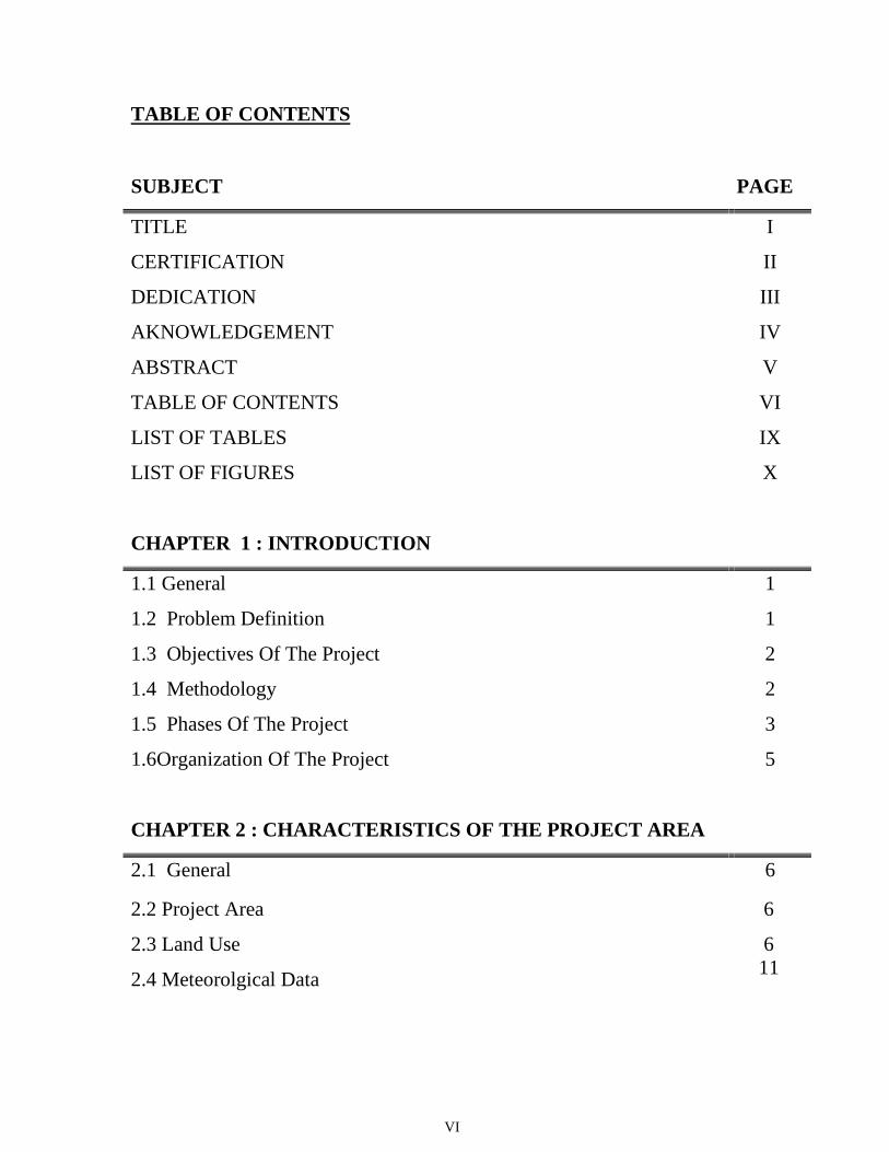
TABLE OF CONTENTS
SUBJECT PAGE
TITLE I
CERTIFICATION II
DEDICATION III
AKNOWLEDGEMENT IV
ABSTRACT V
TABLE OF CONTENTS VI
LIST OF TABLES IX
LIST OF FIGURES X
CHAPTER 1 : INTRODUCTION
1.1 General 1
1.2 Problem Definition 1
1.3 Objectives Of The Project 2
1.4 Methodology
1.5 Phases Of The Project
2
3
1.6Organization Of The Project 5
CHAPTER 2 : CHARACTERISTICS OF THE PROJECT AREA
2.1 General 6
2.2 Project Area
2.3 Land Use
2.4 Meteorolgical Data
6
611
VII
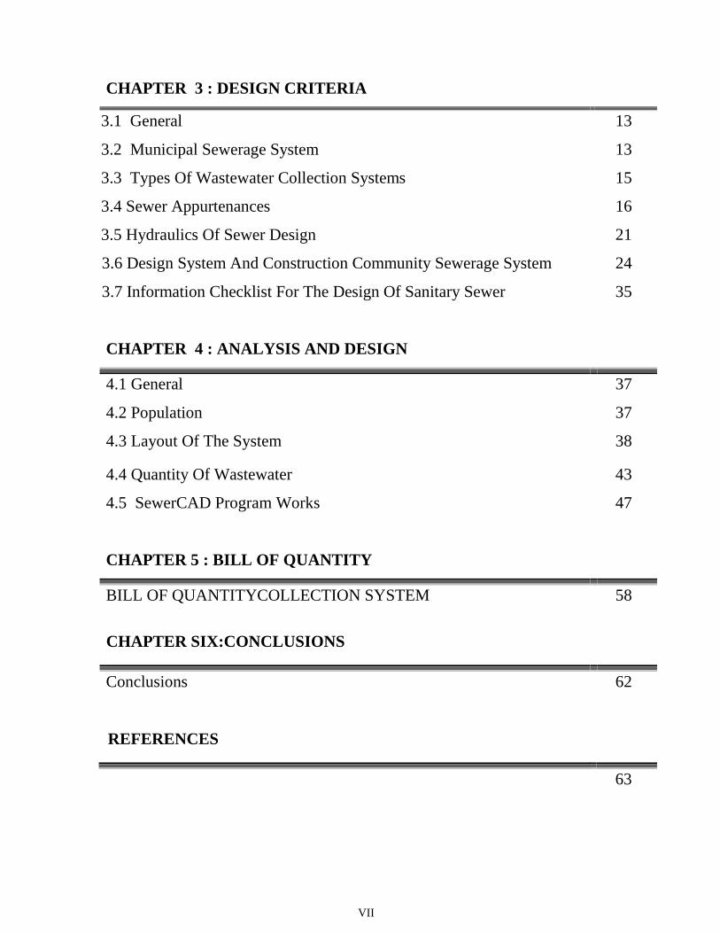
CHAPTER 3 : DESIGN CRITERIA
3.1 3.1 General 13
3.1 3.2 Municipal Sewerage System 13
3.1 3.3 Types Of Wastewater Collection Systems 15
3.1 3.4 Sewer Appurtenances 16
3.1 3.5 Hydraulics Of Sewer Design
3.6 Design System And Construction Community Sewerage System
3.7 Information Checklist For The Design Of Sanitary Sewer
21
24
35
CHAPTER 4 : ANALYSIS AND DESIGN
4.1 General
4.2 Population
37
37
4.3 Layout Of The System 38
4.4 Quantity Of Wastewater
4.5 SewerCAD Program Works
43
47
CHAPTER 5 : BILL OF QUANTITY
BILL OF QUANTITYCOLLECTION SYSTEM 58
CHAPTER SIX:CONCLUSIONS
Conclusions 62
REFERENCES
63

VIII
APPENDIX-A
CALCULATION TABLES. 64
APPENDIX-B
DESIGN TABLES( FROM SEWERCAD)
78
APPENDIX-C
PROFILES FOR PIPES.
IX
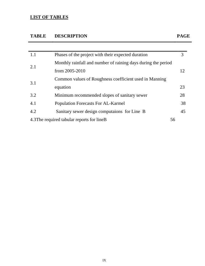
LIST OF TABLES
TABLE DESCRIPTION PAGE
1.1 Phases of the project with their expected duration 3
2.1Monthly rainfall and number of raining days during the period
from 2005-2010 12
3.1Common values of Roughness coefficient used in Manning
equation 23
3.2 Minimum recommended slopes of sanitary sewer 28
4.1 Population Forecasts For AL-Karmel 38
4.2 Sanitary sewer design computaions for Line B 45
4.3The required tabular reports for lineB 56

X
LIST OF FIGURES
FIGURE DESCRIPTION PAGE
2.1 Location plan for AL-Karmel village 7
2.2 Location map for AL-Karmel village respect to other villages 8
2.3 Topography of the project area (AL- Karmel village) 9
2.4 Land use for AL-Karmel village 10
3.1 Types of sewers used in wastewater collection system 14
3.2 Nomograph for solution of Manning formula 30
3.3 Hydraulic properties of circular sewer 31
4.1 Population density of AL-Karmel village 40
4.2Layout of wastewater collection system for AL-Karmel village
with contour lines 41
4.3LLayout of wastewater collection system for AL-Karmel village
without contour lines
42
4.4 Example of wastewater layout, line B 45
4.5 Importing DXF File 47
4.6 Opening The DXF File 47
4.7 Line Example 48
4.8 Creating Project 48
4.9 Defining The Project 49
4.10 Creating a pipe network 49
4.11 Creating Outlet 50

XI
LIST OF FIGURES
4.12 Editing Design Parameters – Part1 50
4.13 Editing Design Parameters– Part2 51
4.14 Editing Design Parameters– Part3 51
4.15 Editing Design Parameters– Part4 52
4.16 Checking The Design 52
4.17 Creating Profile 53
4.18 A Profile A line Sample 54
4.19 Creating Tables55
FIGURE DESCRIPTION PAGE

XII

CHAPTER ONE
1 INTRODUCTION

CHAPTER TWO
2CHARACTERISTICS OF THE PROJECT AREA
CHAPTER THREE

3DESIGN CRITERIA
CHAPTER FOUR

4 ANALYSIS ANDDESIGN
CHAPTER FIVE

BILL OF QUANTITES5
47
CHAPTER SIX

CONCLUSION6
In this project, the trial is made to design waste water collection system for AL-
Karmelvillage considering the annual growth of the people and their water
consumption for the coming 25 years, and catchment area. The result brought out
many important conclusions. The main conclusions drawn from the present study are
summarized below:
1. AL-Karmillike other villages in Palestine has no sewage facility. The people
are using laterains cesspits and septic tanks. The waste water has been seeping
into the ground through the over flow of the deteriorated cesspits and laterains,
causing series environmental and health problem.
2. The proposed waste water collection system for AL-Karmel covers most of
the areas of the village
3. The present water consumption of AL-Karmel is 70 L/c.day and the future
water consumption is estimated to be 120 L/c.day depending on 3.4 %
increase use rate.
4. The collection system is consisting of 6 sewer lines.
5. All lines in the collection system will be design by gravity.
6. The diameter was range between 200 mm to 375 mm
62

REFERENCES
١٩٨٨(. ١ " ( "
.
جامعة _ " ) " ١٩٨٢(. ٢
.
3. Hammer, Mark J. (1977), ''Water and Wastewater Technology'', John Wiley and
sons, INC., U.S.A.
4. Mc Ghee, Terence J. (1991), ''Water Supply and Sewage", Sixth Edition, Mc
Ghee- Hill International Edition, U.S.A.
5. Palestinian Bureau of Statistics (1999), "Locality Type Booklet: Population,
Housing, and Establishment Census", Statistical Reports Series, Ramallah, West
Bank, Palestine.
6. Qasim, Syed R. (1985), "Wastewater treatment plants planning, Design, and
operation". The University of Texas at Arlington, U.S.A.
7. Viessman, Warren.JR. and Hammer, Mark J. (1985)," Water Supply and Pollution
Control', Fourth Edition, Harper and Row, Publishers, Inc., New York, U.S.A.
8. Metcalf &Eddy . (1991), "Wastewater Engineering: Treatmant , Disposal ,and Reuse" , 3rd Edition, McGraw – Hill Co.
9. Operation of Municipal Wastewater Treatment Plants Water Pollution ControlFederation , USA , 1994 .
10. WaelAwadallah , "Sewage Treatment by a UASB-Wetlands System for Asmall Community" . (2006) ,
63

APPENDIX A
CALCULATION TABLES
64

APPENDIX B
DESIGN TABLES( FROM SEWERCAD)
78

CHAPTER ONE INTRODUCTION
1
1.1 General
Drainage is the term applied to systems for dealing with excess water. It is importante for the
disposal of surplus irrigation water, storm water, and wastewater.Water drainage is a natural
phenomenon which takes place naturaly and depends on the geomorphological and hydrological
features, water drainage is often considered as minor problem, but with rapid increase in
population and concequent in all round activities of man, the problem has been accentuated.
The wide expansion and accelerated development of Al-Karmel village had led to change in the
hydrological and geomorphological features and the drainage system had become more complex,
hence the amount of wastewater and running water has increased. At the same time wastewater
collection system are not exist.
In view of this prevailing condition, the drainage system in Al-Karmelvillage would have a new
characteristics . This study is conducted to design a wastewater collection system for Al-Karmel
village.
Al-Karmel like other village in Palestine have no sewerge facility. The people are using latrines,
cesspits and few of them use septic tanks, which are emptied by cesspit emptier and tankers from
time to time. These latrines and cesspits are deteriorating and they are in very bad condition,
adding to this the increasing water consumption and consequently increasing in wastewater
production resulting in over flows from the cesspits and excessive recharge of ground water in
Al-Karmel area. For all the reasons mentioned, this evaluation and design of wastewater
collection system for Al-Karmel have been conducted.
1.2 Problem Definition
The acceleration expansion and developed of Al-Karmel has resulted in increasing of water
consumption and consequently in generation of large quantities of wastewater from various
sources such as residential areas, commercial establishments and different industries. Due to the
absence of wastewater collection system, the wastewater has been seeping into the ground
through the overflows of the deteiorated cesspits and latrines that are commonly used in Al-
Karmel Moreover, in some areas wastewater is flows to the wadis through open drains in

CHAPTER ONE INTRODUCTION
2
different routes causing serious environmental and health problems.
The main damaging consequences of these wastewater routes are offensive adors and smells,
proper media for breeding of mosquitoes, soil contamination and polluting of the existing
aquifers. The municipality of Al-Karmel is receiving on daily bases complains from the people
asking a comprehensive solution for the wastewater problems in the village.
In view of these bad conditions, and since there is no seweage networks exist, along with fast
increasing of the environmental and health problem. The design of wastewater collection system
study become a pressing necessity so as to solve all problems that were mentioned above. This
study will consider the annual growth of the people and their water consumption for the coming
25 years, which will be the design period, along with the commercial industrial development in
the area .
1.3 Objecives Of The Project
The main objectives of this project are:-
1. Division of Al-Karmel area into catchment and sub-catchment areas according to existing
situation and the topographic maps and classifying them into classes.
2. Estimation of population and their densities for the design period for each catchment area.
3. Determination of the water consumption and consequently the wastewater production
from the different sources for each catchment area.
4. Evaluation of the collected data, propose collection system of the village and design of the
main trunks of the network.
5. Showing the proposed wastewater network its parts on different maps for different
purposes.
6. Preparation of Bill of Quantities for the main trunks.
1.4 Methadology
1. Many site visits to Al-Karmel village and Municipality were done.
2. All needed maps and the previous studies that contain different information about AL-
Karmel were obtained.
CHAPTER ONE INTRODUCTION
3
3. The amounts of water consumption for different purposes and consequently the amounts
of wastewater production for each area were obtained.
4. The different layouts of the proposed wastewater collection system are ploted.
5. The necssary hydraulic calculation for the systems and other design reqirements will be
carried out in the next semester.
6. Bill of quantity of the designed wastewater main trunks will be prepared with needed
recommendations.
7. Finalizing of the project that will contain the report and the needed maps and drawings.
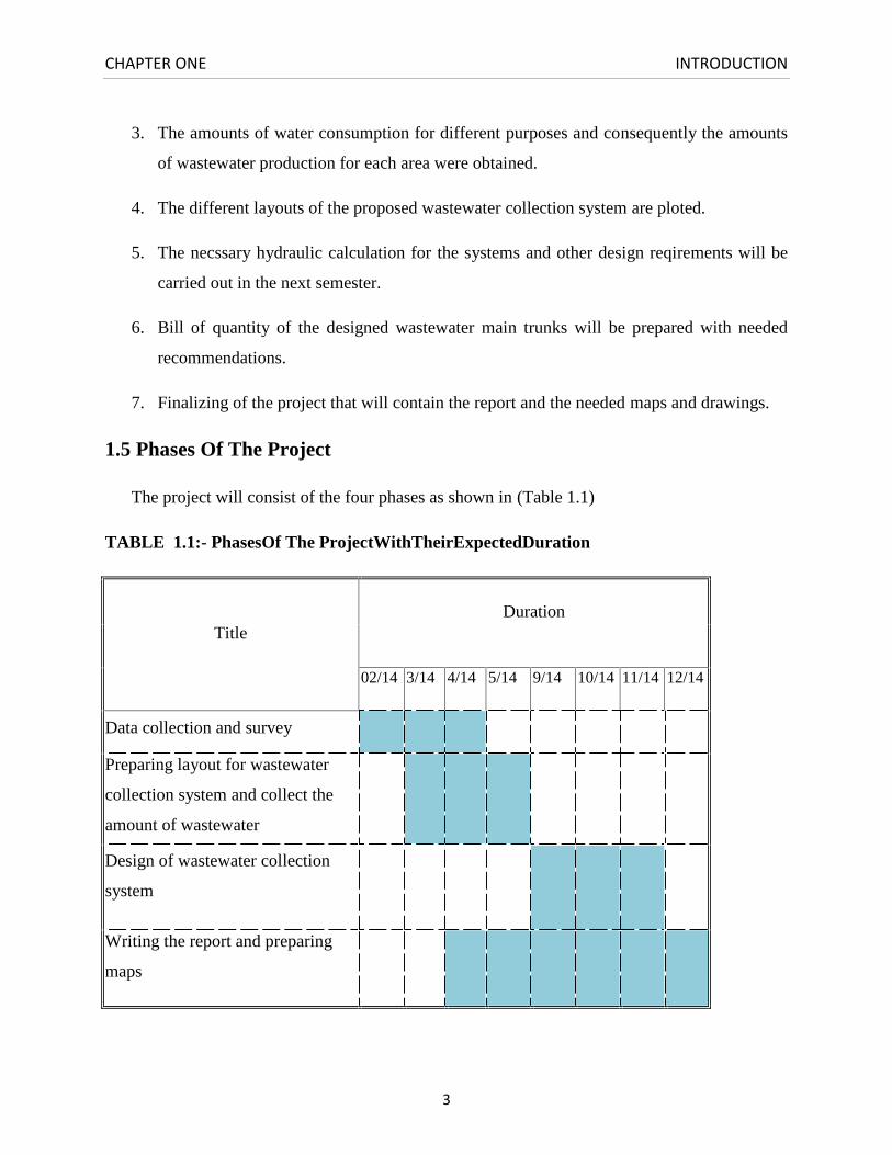
1.5 Phases Of The Project
The project will consist of the four phases as shown in (Table 1.1)
TABLE 1.1:- PhasesOf The ProjectWithTheirExpectedDuration
TitleDuration
02/14 3/14 4/14 5/14 9/14 10/14 11/14 12/14
Data collection and survey
Preparing layout for wastewater
collection system and collect the
amount of wastewater
Design of wastewater collection
system
Writing the report and preparing
maps

CHAPTER ONE INTRODUCTION
4
1.5.1 First phase:- Data Collection And Survey
In this phase, available data and information were collected from different sources. Moreover,
many site visits to both the village and the municipality were done. This phase include the
following tasks.
1. Collecting of topographical maps for all the area.
2. Collecting of meteorological and hydrological data(temperature, wind , speed, rainfall,
evapoeration…etc) from different sources.
3. Evaluation of population densities in each zone of the village with their
waterconsumption and predicting their numbers, densities and their water consumption in
year2039.
1.5.2 Second Phase:-Preparing Layout For The Network And Calculate The Amount
OfWasteWater.
In this phase layout will prepared and put in its final shape and then quantities of wastewater will
determine.
This phase include the following tasks:
1. Draw the layout of the network and compare it with the real setuation in Al-
Karmelvillage then make adjusment and last draw the final layout , this task is the
most improtant.
2. Evaluation of the contour maps and matching it with actual ground levels in the
village.
3. Determination of the wastewater quantities.
4. Determination of the wastewater quantities and projection of the wastewater
production in year 2039.
1.5.3 Third Phase:- Design Of WasteWaterCollection Systems
In this phase the necessary hydraulic calculation needed for the design of the main trunks will be
carried out. This phase include the following tasks:
1. Establish a system layout, which includes the areas that are going to be served,
topography…etc.

CHAPTER ONE INTRODUCTION
5
2. Establish the catchments and sub-catchments areas and routes of the sewers.
3. Establish the design criteria and conducting the needed sewer diameter hydraulic
calculations.
4. Preparing needed different drawings for the designed sewers.
1.5.4 Fourth Phase:- Writing The Report And Other Needed Jobs
After finishing the design calculation of the main trunks the project team prepared the
specifications drawing, bill of quantities and preliminary maps.Final report of the project was
prepared and submitted to the Department of civil and Architectural Engineering at Palestine
Polytechnic University.
1.6 Organization Of The Project
The study report has been prepared in accordance with the objectives and scope of work. The
report consists of five chapters. The first chapter entitled “Introduction” outlines the problem,
project objectives, and phases of the project.
Chapter two entitled “Characteristic Of The Project Area” presents basic background data and
information on the project area, water supply, wastewater disposal.
Chapter three entitled “Design Criteria” deals with municipal sewage system, types of
wastewater collection systems, sewer appurtenances, flow in sewers, design of sewer system, and
sewer construction and maintenance.
Chapter four entitled “Analysis And Design” presents the design calculations and maps of the
system, chapter five “Bill Of Quantities” deals with the quantities of excavation, backfilling, pipe
and manholes.
Chapter six entitled “Conclusions” discusses the conclusions of the study.

CHAPTER ONE INTRODUCTION
6
CHAPTER TWO CHARACTERISTICS OF THE PROJECT AREA
6
2.1 General
In this chapter, the basic data of AL-Karmel village will be briefly discussed. The topography,
population water consumption, and wastewater production will be briefly presented.
2.2 Project Area
Al-Karmel situated 18 Km to the south of Hebron city, as shown on the project location plan
Figure (2.1), and the location of village respect to other villagesis shown on Figure (2.2) .
The average hight of the village is 807 m with respect to sea level,the ground elevations rangefrom 820 m in center of the village to around 750 m in the east part of the village.The total areaof the village is about 7400donum.
The topography within the village is mountainous and rugged. As shown on Figure (2.3).
The population within the municipal administrative borders in year 2014is around 6400persons.
This population is expected to grow substantially up to the year 2039 planning horizon of this
project.
2.3 Land Use
As mentioned earlier, the land area of AL-Karmelvillage is approximately 7400 donum. There is
no clear town plan defining land use in the various zones of AL-karmel. The land use can be
distributed as follows:-
1. Old village : This area is consists of old buildings which have a historical importance,
these buildings are used as resedinces, workshops, public building, and cemetry. Some of
these buildings are very old and need to be maintained.
2. Old village surrounding: The land use of AL-Karmel shown in Figure (2.4) is distributed
as follow :-
1. Residential areas, food stories, workshop building, public buildings.
2. Agricultural areas.
3. Roads.

CHAPTER TWO CHARACTERISTICS OF THE PROJECT AREA
7

CHAPTER TWO CHARACTERISTICS OF THE PROJECT AREA
8

CHAPTER TWO CHARACTERISTICS OF THE PROJECT AREA
9

CHAPTER TWO CHARACTERISTICS OF THE PROJECT AREA
10

CHAPTER TWO CHARACTERISTICS OF THE PROJECT AREA
11
2.4Meteorological Data
The hydrology of the region depends primarily on its climate, and secondarily on its topography.
Climate is largely dependent on geographical position of the earth surface humidity, temperature,
and wind. These factors affect are affecting evaporation and transpiration. So this study will
include needed data about these factors, since they play big role in the determination of water
demand.
The climate of AL-Karmelvillage tends to be cold in winter with limited amount of rain, and
warm in summer with relative humid.
2.4.1 Temperature
The temperature is characterized by considerable variation between summer and winter times.
The mean temperature values at AL-Karmel for the period 1995 to 2000 are given in below.
The Mean maximum temperature: 31˚C
The Mean minimum temperature: 8˚C
The Mean Maximum temperature record: 30˚C
The Mean Minimum temperature record: 4.4˚C
2.4.2 Relative Humidity
Since AL-Karmelis situated at considerable distance from the sea in a mountains region on the
outskirts of the desert, AL-Karmel has low values of relative humidity compared to those in the
plains. The relative humidity in AL-Karmel village range from 54-78%, it reaches the maximum
value in January (78%).
2.4.3 Wind
The directions and velocities of wind vary depending on the season of the year. In winter, the
wind blows in the morning from the southwest a rounds noon from southwest and west, and at
night from west and northwest. In summer, northeasterly wind blows all day long. According to
data obtained from Meteorological Station, average wind in winter is about 9.8km/h and in
summer 5.4km.
CHAPTER TWO CHARACTERISTICS OF THE PROJECT AREA
12
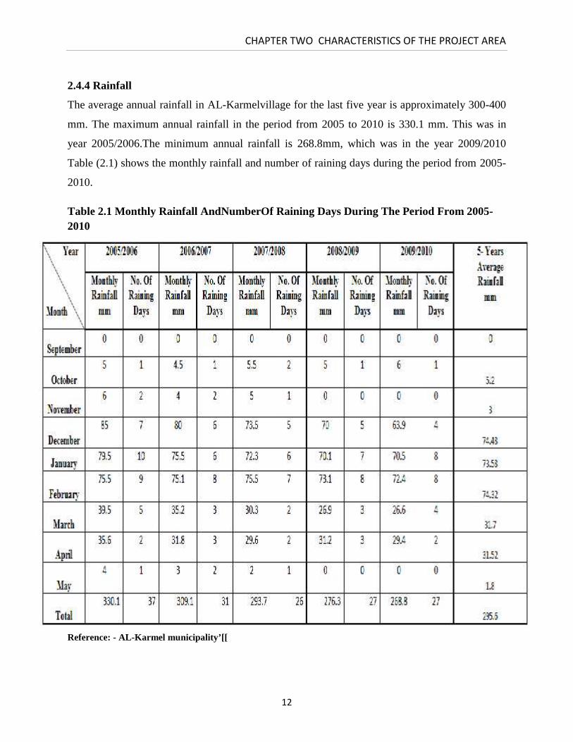
2.4.4 Rainfall
The average annual rainfall in AL-Karmelvillage for the last five year is approximately 300-400
mm. The maximum annual rainfall in the period from 2005 to 2010 is 330.1 mm. This was in
year 2005/2006.The minimum annual rainfall is 268.8mm, which was in the year 2009/2010
Table (2.1) shows the monthly rainfall and number of raining days during the period from 2005-
2010.
Table 2.1 Monthly Rainfall AndNumberOf Raining Days During The Period From 2005-2010
Reference: - AL-Karmel municipality’[[

CHAPTER TWO CHARACTERISTICS OF THE PROJECT AREA
13

CHAPTER TWO CHARACTERISTICS OF THE PROJECT AREA
14

CHAPTER TWO CHARACTERISTICS OF THE PROJECT AREA
15

CHAPTER THREE WASTE WATER COLLECTION SYSTEM
13
3.1 GENERAL
Once used for its intended purposes, the water supply of a community is
considered to be wastewater. The individual conduits used to collect and transport
wastewater to the treatment facilities or to the point of disposal are called sewers.
There are three types of sewers: sanitary, storm, and combined. Sanitary sewers are
designed to carry wastewater from residential, commercial, and industrial areas, and a
certain amount of infiltration /inflow that may enter the system due to deteriorated
conditions of sewers and manholes. Storm sewers are exclusively designed to carry
the storm water. Combined sewers are designed to carry both the sanitary and the
storm flows.
The network of sewers used to collect wastewater from a community is known as
wastewater collection system. The purpose of this chapter is to define the types of
sewers used in the collection systems, types of wastewater collection systems that are
used, the appurtenances used in conjunction with sewers, the flow in sewers, the
design of sewers, and the construction and maintenance of sewers.
3.2 MUNICIPAL SEWERAGE SYSTEM
3.2.1 Types of Sewers
The types and sizes of sewers used in municipal collection system will vary with size
of the collection system and the location of the wastewater treatment facilities. The
municipal or the community sewerage system consists of (1) building sewers (also

CHAPTER THREE WASTE WATER COLLECTION SYSTEM
14
called house connections), (2) laterals or branch sewers, (3) main and submain
sewers, (4) trunk sewers, and (5) intercepting sewers.
House sewers connect the building plumbing to the laterals or to any other sewer lines
mentioned above. Laterals or branch sewers convey the wastewater to the main
sewers. Several main sewers connect to the trunk sewers that convey the wastewater
to large intercepting sewers or the treatment plant. The types of sewers usually used
in wastewater collection system are shown in Figure 3.1 (Qasim, 1985).
Figure (3.1): Types Of Sewers Used In Wastewater Collection System
CHAPTER THREE WASTE WATER COLLECTION SYSTEM
15
The diameter of a sewer line is generally determined from the peak flow that the line
must carry and the local sewer regulations, concerning the minimum sizes of the
laterals and house connections. The minimum size recommended for gravity sewer is
200 mm (8 in).
3.2.2 Sewer Materials
Sewers are made from concrete, reinforced concrete, vitrified clay, asbestos cement,
brick masonry, cast iron, ductile iron, corrugated steel, sheet steel, and plastic or
polyvinyl chloride (PVC) or ultra polyuinyl chloride (uPVC). Concrete and ultra
polyvinyl chlorides are the most common materials for sewer construction.
3.3 TYPES OF WASTEWATER COLLECTION SYSTEMS
3.3.1 Gravity Sewer System
Collecting both wastewater and storm water in one conduit (combined system) or in
separate conduits (separate system). In this system, the sewers are partially filled. A
typical characteristic is that the gradients of the sewers must be sufficient to create
self-cleansing velocities for the transportation of sediment. These velocities are 0.6 to
0.7 m/s when sewers are flowing full or half-full. Manholes are provided at regular
intervals for the cleaning of sewers.
3.3.2 Pressure Type System
Collecting wastewater only. The system, which is entirely kept under pressure, can
be compared with a water distribution system. Sewage from an individual house
connection, which is collected in manhole on the site of the premises, is pumped into
the pressure system. There are no requirements with regard to the gradients of the
sewers.
CHAPTER THREE WASTE WATER COLLECTION SYSTEM
16
3.3.3 Vacuum Type System
Collecting wastewater only in an airtight system. A vacuum of 5-7 m is maintained
in the system for the collection and transportation of the wastewater. There is no
special requirement for the gradients of the sewers.
Pressure and vacuum–types systems require a comparatively high degree of
mechanization, automation and skilled manpower. They are often more economical
than gravity system, when applied in low population density and unstable soil
conditions. Piping with flexible joints has to be used in areas with expansive soils.
3.4 SEWER APPURTENANCES
3.4.1 Manholes
Manholes should be of durable structure, provide easy access to the sewers for
maintenance, and cause minimum interference to the sewage flow. Manholes should
be located at the start and at the end of the line, at the intersections of sewers, at
changes in grade, size and alignment except in curved sewers, and at intervals of 90-
180 m in straight lines.
The general shapes of the manholes are square, rectangular or circular in plan, the
latter is common. Manholes for small sewers are generally 1.0-1.2 m in diameter. For
larger sewers larger manhole bases are provided. The maximum spacing of manholes
is 90-180 m depending on the size of sewer and available size of sewer cleaning
equipment (Qasim,1985).
Standard manholes consist of base, risers, top, frame and cover, manhole benching,
CHAPTER THREE WASTE WATER COLLECTION SYSTEM
17
and step-iron. The construction materials of the manholes are usually precast
concrete sections, cast in place concrete or brick. Frame and cover usually made of
cast iron and they should have adequate strength and weight.
Drop Manholes
A drop manhole is used where an incoming sewer, generally a lateral, enters the
manhole at a point more than about 0.6 m above the outgoing sewer. The drop pipe
permits workmen to enter the manhole without fear of being wetted, avoid the
splashing of sewage and corrosion of manhole bottom.
3.4.2 House Connections
The house sewers are generally 10-15 cm in diameter and constructed on a slop of
0.02 m/m. house connections are also called, service laterals, or service connections.
Service connections are generally provided in the municipal sewers during
construction. While the sewer line is under construction, the connections are
conveniently located in the form of wyes or tees, and plugged tightly until service
connections are made. In deep sewers, a vertical pipe encased in concrete is provided
for house connections (Qasim, 1985).
3.4.3 Inlets
Inlets are structures through which storm water enters the sewers. Their design and
location require consideration of how far water will be permitted to extend into the
CHAPTER THREE WASTE WATER COLLECTION SYSTEM
18
Street under various conditions. The permissible depth of water in the gutter is
limited to 150 mm on residential streets and to that depth, which will leave two lanes,
clear of standing water on arterials and one lane on major streets (Mc Ghee, 1991).
3.4.4 Inverted Siphons
An inverted siphon is a section of sewer, which is dropped below the hydraulic grade
line in order to avoid an obstacle such as a railway or highway cut, a subway, or a
stream. Such sewers will flow full and will be under some pressure; hence they must
be designed to resist low internal pressures as well as external loads. It is also
important that the velocity be kept relatively high (at least 0.9 m/s) to prevent
deposition of solids in locations, which would be very difficult or impossible to clean
(Mc Ghee, 1991).
Since sewage flow is subject to large variation, a single pipe will not serve
adequately in this application. If it is small enough to maintain a velocity of 0.9 m/s
at minimum flow, the velocity at peak flow will produce very high head losses and
may actually damage the pipe. Inverted siphons normally include multiple pipes and
an entrance structure designed to divide the flow among them so that the velocity in
those pipes in use will be adequate to prevent deposition of solids (Mc Ghee, 1991).
3.4.5 Sewer Outlets and Outfalls
Storm water and treated wastewater may be discharged to surface drainage or to
bodies of water such as lakes, estuaries, or the ocean. Outlets to small streams are
similar to the outlets of high way culverts, consisting of simple concrete headwall
CHAPTER THREE WASTE WATER COLLECTION SYSTEM
19
and apron to prevent erosion. Some wastewater treatment plants are located at
elevations, which might be flooded. Present regulations require that sewage
treatment works be protected against a 100-year flood, which may require levees
around low-lying installations and pumping of the treated flow when stream levels
are high. Gravity discharge line in such circumstances must be protected by flap
gates or other automatically closed valves, which will prevent the stream flow from
backing up into the plant (Mc Ghee, 1991).
Sewers discharging into large bodies of water are usually extended beyond the banks
into fairly deep water where dispersion and diffusion will aid in mixing the discharge
with the surrounding water. The outfall lines are constructed of either iron or
reinforced concrete and may be placed from barges or joined by divers. Iron is
generally preferred for outfall 610 mm in diameter or less. In bodies of water which
are sufficiently large to permit heavy wave action. The outfall may be protected by
being placed in a dredged trench or by being supported on pile bents. Subsurface
discharges normally employ multiple outlets to aid in distribution and dilution of the
wastewater (Mc Ghee, 1991).
3.4.6 Pumping of Sewer
There are many communities in which it is possible to convey all the sewage to a
central treatment location or point of discharge in only a gravity system. In other
areas with flat terrain, more than one drainage area, low-lying sections, or similar
complications, pumping may be required. Pumping may also be required at or within
sewage treatment plants, in the basements of buildings which are below the grade of
CHAPTER THREE WASTE WATER COLLECTION SYSTEM
20
the sewer, and to discharge treated wastewater to streams which are above the
elevation of the treatment plant (Mc Ghee, 1991).
Pumping of untreated sanitary sewage requires special designs, since sewage often
contains large solids. Nonclog pumps have impellers, which are usually closed and
have, at most, two or three vanes. The clearance between the vanes is sufficiently
large that anything, which will clear the pump suction, will pass through the pump. A
bladeless impeller, sometimes used as a fish pump, has also been applied to this
service. For a specified capacity, bladeless impellers are larger and less efficient than
vaned designs (Mc Ghee, 1991).
Sewage pumping stations within the collection system include a wet well, which
serves to equalize the incoming flow, which is always variable. Although pumps that
can operate at variable speed are available, their cost and the complexity of their
control systems generally make them an expensive alternative. Ordinary constant-
speed pumps with standard motors should not be turned on and off too frequently
since this can cause them to overheat. In small pumping stations there may be only
two pumps, each of which must be able to deliver the maximum anticipated flow.
Lower flows are allowed to accumulate in the wet well until a sufficient volume has
been accumulated to run the pump for about 2 min. The wet well may also be sized
to ensure that the pump will not start more often than once in about 5 minutes. The
specific values of running time and cycle time depends upon the characteristics of the
motor used and must be obtained from the manufacturers (Mc Ghee, 1991).
CHAPTER THREE WASTE WATER COLLECTION SYSTEM
21
3.5 HYDRAULICS OF SEWER DESIGN
3.5.1 Introduction
Wastewater systems are usually designed as open channels except where lift stations
are required to overcome topographic barriers. The hydraulic problems associated
with these flows are complicated in some cases by the quality of the fluid, the highly
variable nature of the flows, and the fact that an unconfined or free surface exists.
The driving force for open-channel flow and sewer flow is gravity. For the hydraulic
calculations of sewers, it is usually assumed uniform flow in which the velocity of
flow is constant, and steady flow condition in which the rate discharge at any point
of a sewer remains constant (Metcalf,1982).
3.5.2 Flow Formulas
In principle all open channel flow formulas can be used in hydraulic design of sewer
pipes through Manning’s formula. The following are the most important formulas:
1. Chezy formula: Using the Chezy equation, the velocity of flow in sewers can
be determined according to
V = C√RS (3.1)
Where V is the velocity of flow, C is the Chezy coefficient (C = 100 R/(m+ √R),
where m = 0.35 for concrete pipe or 0.25 for vitrified clay pipe), R is the
hydraulic radius, and S is the slope of the sewer pipe.
2. Darcy-Weisbach formula: It is not widely used in wastewater collection
design and evaluation because a trial and error solution is required to determine
pipe size for a given flow and head loss, since the friction factor is based on the
CHAPTER THREE WASTE WATER COLLECTION SYSTEM
22
relative roughness which involves the pipe diameter, making it complicated.
Darcy-Weishbach formula states that
H = λ L*V2/(D*2g) (3.2)
Where H is the pressure head loss in mwc, L is the length of pipe, D is the
diameter of pipe, λ is the dimensionless friction factor generally varying between
0.02-0.075.
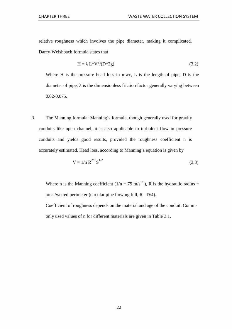
3. The Manning formula: Manning’s formula, though generally used for gravity
conduits like open channel, it is also applicable to turbulent flow in pressure
conduits and yields good results, provided the roughness coefficient n is
accurately estimated. Head loss, according to Manning’s equation is given by
V = 1/n R2/3
S1/2
(3.3)
Where n is the Manning coefficient (1/n = 75 m/s1/3), R is the hydraulic radius =
area /wetted perimeter (circular pipe flowing full, R= D/4).
Coefficient of roughness depends on the material and age of the conduit. Comm-
only used values of n for different materials are given in Table 3.1.

CHAPTER THREE WASTE WATER COLLECTION SYSTEM
23
Table 3.1:Common Values of Roughness Coefficient Used in the Manning Equation
3.5.3 Hydraulics of Partially Filled Sections
The filling rate of a sewer is an important consideration, as sewers are seldom
running full, so sanitary sewers designed for 40% or 50% running full, that is
means only 40 % to 50 % of the pipe capacity should be utilized to carry the peak
flow.
Partially filled sewers are calculated by using partial flow diagram and tables
indicating the relation between water depth, velocity of flow and rate flow .The
hydraulic characteristics are similar as for open channels, but the velocity of flow is
reduced by increased air friction in the pipe with increasing water level, particularly
near the top of the pipe. The velocity of flow and the flow rate are reduced at filling
rates between 60% and 100%; the water level in the pipe is unstable at filling rates
above 90% or 95%.
Commonly Used Values of n Material
0.013 and 0.015 Concrete
0.013 and 0.015 Vitrified clay
0.013 and 0.015 Cast iron
0.015 and 0.017 Brick
0.022 and 0.025 Corrugated metal pipe
0.013 and 0.015 Asbestos cement
0.025 and 0.003 Earthen channels
CHAPTER THREE WASTE WATER COLLECTION SYSTEM
24
3.6 DESIGN SYSTEM AND CONSTRUCTION
COMMUNITY SEWERAGE SYSTEM
Designing a community sewerage system is not a simple task. It requires
considerable experience and a great deal of information to make proper decisions
concerning the layout, sizing, and construction of a sewer network that is efficient
and cost-effective. The design engineer needs to generally undertake the following
tasks (Qasim,1985, Peavy,1985):
1- Define the service area.
2- Conduct preliminary investigations.
3- Develop preliminary layout plan and profile.
4- Selection of design parameters.
5- Review construction considerations.
6- Conduct field investigation and complete design and final profiles.
7- Prepare contract drawing and specifications.
3.6.1 Service Area
Service area is defined as the total area that will eventually be served by the sewage
system. The service area may be based on natural drainage or political boundaries, or
both. It is generally a part of the area wide waste management plan.
3.6.2 Preliminary Investigations
The design engineer must conduct the preliminary investigations to develop a layout
plan of the sewerage system. Site visits and contacts with the city and local planning
CHAPTER THREE WASTE WATER COLLECTION SYSTEM
25
agencies and state officials should be made to determine the land use plans, zoning
regulations, and probable future changes that may affect both the developed and
undeveloped land. Data must be developed on topography, geology, hydrology,
climate, ecological elements, and social and economic conditions. Topographic maps
with existing and proposed streets and other utility lines provide the most important
information for preliminary flow routing (Qasim, 1985).
If reliable topographic maps are not available, field investigations must be conducted
to prepare the contours, place bench marks, locate building, utility lines, drainage
ditches, low and high areas, stream, and the like. All these factors influence the
sewer layout.
3.6.3 Layout Plan
Proper sewer layout plan and profiles must be completed before design flows can be
established. The following is a list of basic rules that must be followed in developing
a sewer plan and profile (Qasim, 1985):
1. Select the site for the wastewater treatment plant. For gravity system, the best site
is generally the lowest elevation of the entire drainage area.
2. The preliminary layout of sewers is made from the topographic maps. In general,
sewers are located on streets, or on available right-of-way; and sloped in the
same direction as the slope of the natural ground surface.
3. The trunk sewers are commonly located in valleys. Each line is started from
the intercepting sewer and extended uphill until the edge of the drainage area is
reached, and further extension is not possible without working downhill.
CHAPTER THREE WASTE WATER COLLECTION SYSTEM
26
4. Main sewers are started from the trunk line and extended uphill intercepting
the laterals.
5. All laterals or branch lines are located in the same manner as the main sewers.
Building sewers are directly connected to the laterals.
6. Preliminary layout and routing of sewage flow is done by considering several
feasible alternatives. In each alternative, factors such as total length of sewers;
and cost of construction of laying deeper lines versus cost of construction,
operation, and maintenance of lift station, should be evaluated to arrive at a cost-
effective sewerage system.
7. Sewers should not be located near water mains. State and local regulations
must be consulted for appropriate separation distance between the sewers and
water lines.
8. After the preliminary sewer layout plan is prepared, the street profiles are
drawn. These profiles should show the street elevations, existing sewer lines, and
manholes. These profiles are used to design the proposed lines.
3.6.4 Selection of Design Parameters
Many design factors must be investigated before sewer design can be completed.
Factors such as design period; peak, average, and minimum flows; sewer slopes and
minimum velocities; design equations; etc. are all important in developing sewer
design. Many of the factors are briefly discussed below.
1. Design Period: Design period should be based on ultimate tributary population. It
is not uncommon to design sewers for a design period of 25-50 years or more.
CHAPTER THREE WASTE WATER COLLECTION SYSTEM
27
2. Design Population: Population projections must be made for the population at
the end of the design year. Discussion on population projection can be found in
chapter four.
3. Design Flow Rate: Sanitary sewers should be designed to carry peak residential,
commercial, and industrial flows, and the normal infiltration and inflow where
unfavorable conditions exist.
4. Minimum Size: As mentioned earlier, minimum sewer size recommended is 20
cm (8 in). Many countries allow 15 cm (6 in) lateral sewers.
5. Minimum and Maximum Velocities: In sanitary sewers, solids tend to settle
under low-velocity conditions. Self-cleaning velocities must be developed
regularly to flush out the solids. Most countries specify minimum velocity in the
sewers under low flow conditions. A good practice is to maintain velocity above
0.3 m/s under low flow conditions. Under peak dry weather condition, the lines
must attain velocity greater than 0.6 m/s. This way the lines will be flushed out at
least once or twice a day. In depressed sewers self-cleaning velocities of 1.0 m/s
must be developed to prevent accumulation of solids. Velocities higher than 3
m/s should be avoided as erosion and damage may occur to the sewers or
manholes.
6. Slope: Flat sewer slopes encourage solids deposition and production of hydrogen
sulfide and methane. Hydrogen sulfide gas is odorous and causes serious pipe
CHAPTER THREE WASTE WATER COLLECTION SYSTEM
28
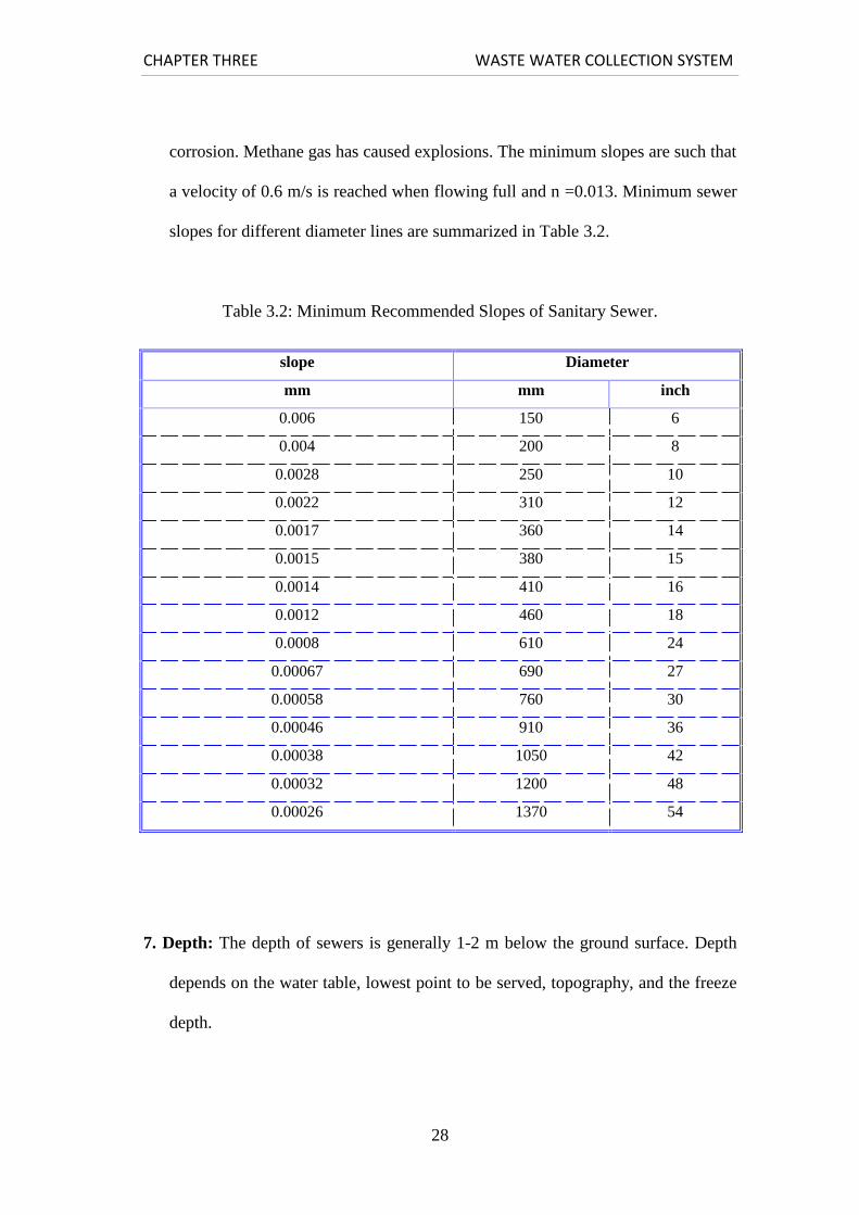
corrosion. Methane gas has caused explosions. The minimum slopes are such that
a velocity of 0.6 m/s is reached when flowing full and n =0.013. Minimum sewer
slopes for different diameter lines are summarized in Table 3.2.
Table 3.2: Minimum Recommended Slopes of Sanitary Sewer.
7. Depth: The depth of sewers is generally 1-2 m below the ground surface. Depth
depends on the water table, lowest point to be served, topography, and the freeze
depth.
slope Diameter
mm mm inch
0.006 150 6
0.004 200 8
0.0028 250 10
0.0022 310 12
0.0017 360 14
0.0015 380 15
0.0014 410 16
0.0012 460 18
0.0008 610 24
0.00067 690 27
0.00058 760 30
0.00046 910 36
0.00038 1050 42
0.00032 1200 48
0.00026 1370 54
CHAPTER THREE WASTE WATER COLLECTION SYSTEM
29
8. Appurtenances: Sewer appurtenances include manholes, building connections,
inlets, inverted siphons, outlets and outfall, and others. These are discussed
briefly in section 3.4. Appropriate sewer appurtenances must be selected in
design of sanitary sewers. Manholes for small sewers are generally 1.2 m in
diameter. For larger sewers larger manhole bases are provided. The maximum
spacing of manholes is 90-180 m.
9. Design Equations and Procedures: Sanitary sewers are mostly designed to flow
partially full. Once the peak, average, and minimum flow estimates and made
general layout and topographic features for each line are established, the design
engineer begins to size the sewers. Design equations proposed by Manning,
Chezy, Gangullet, Kutter, and Scobey have been used for designing sewers and
drains. The Manning equation, however, has received most widespread
application. This equation in various forms is expressed below:
V = 1/n R2/3
S1/2
(3.3)
Q = (0.312 /n) D 8/3 S 1/2 (circular pipe flowing full) (3.4)
Where Q is the flow rate.
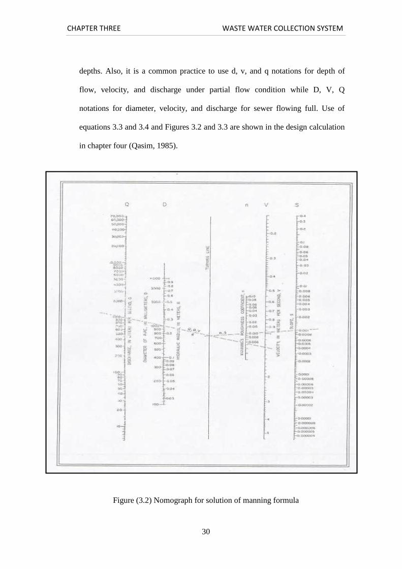
Various types of nomographs have been developed for solution of problems
involving sewers flowing full. Nomographs based on Manning’s equation for
circular pipe flowing full and variable n values are provided in Figure 3.2.
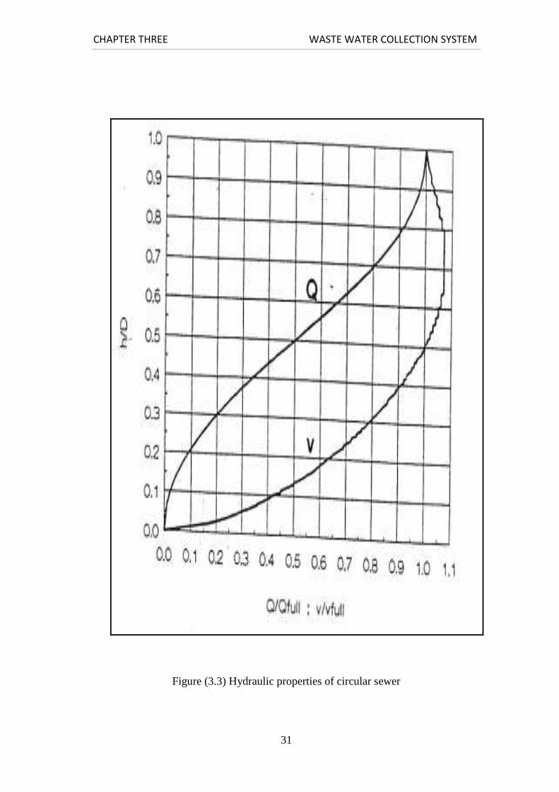
Hydraulic elements of circular pipes under part-full flow conditions are provided
in Figure 3.3. It may be noted that the value of n decreases with the depth of
flows Figure 3.2. However, in most designs n is assumed constant for all flow
CHAPTER THREE WASTE WATER COLLECTION SYSTEM
30
depths. Also, it is a common practice to use d, v, and q notations for depth of
flow, velocity, and discharge under partial flow condition while D, V, Q
notations for diameter, velocity, and discharge for sewer flowing full. Use of
equations 3.3 and 3.4 and Figures 3.2 and 3.3 are shown in the design calculation
in chapter four (Qasim, 1985).
Figure (3.2) Nomograph for solution of manning formula
CHAPTER THREE WASTE WATER COLLECTION SYSTEM
31
Figure (3.3) Hydraulic properties of circular sewer
CHAPTER THREE WASTE WATER COLLECTION SYSTEM
32
After the preliminary sewer layout plan and profile are prepared, the design
computations are accomplished. Design computations for sewers are repetitious and
therefore, are best performed in a tabular format.
3.6.5 Construction Consideration
1. Construction Materials: As mention earlier, sewers are made from concrete,
reinforced concrete, vitrified clay, asbestos cement, brick masonry, cast iron,
corrugated steel, sheet steel, and plastic. Important factors in selection of sewer
material include the following:
- Chemical characteristics of wastewater and degree of resistance to corrosion
against acid, base, gases, solvent, etc.
- Resistance to scour and flow.
- External forces and internal pressure
- Soil conditions.
- Type of backfill and bedding material to be used.
- Useful life.
- Strength and water tightness of joints required, and effective control of infiltration
and inflow.
- Availability in diameter, length, and ease of installation.
- Cost of construction and maintenance.
2. Joints and Infiltration: The method of making joints should be fully covered
in the specifications. Joints should be designed to make sewers water-tight, root-
resistant, flexible, and durable. A leakage test should be specified. The leakage
shall not exceed 0.5 m3 per day per cm of pipe diameter per Km. It has been
CHAPTER THREE WASTE WATER COLLECTION SYSTEM
33
experimentally demonstrated that joints made from rubber gasket and hot-poured
bituminous material produced almost no infiltration, whereas cement mortar
joints cause excessive infiltration.
3. Sewer Construction: Sewer construction involves excavation, sheeting and
bracing of trenches, pipe installation, and backfilling. Each of these construction
steps is discussed briefly below (Qasim,1985).
- Excavation: After the sewer alignment is marked on the ground, the trench
excavation being. Machinery such as backhoe, clamshell, dragline, front-end
loader or other specialized equipment is used. Hand excavation may be possible
only for short distances. Hard rocks may be broken by drilling; explosives may
also be used where situations permit.
- Sheeting and Bracing: Trenches in unstable soil condition require sheeting
and bracing to prevent caving. Sheeting is placing planks in actual contact with
the trench sides. Bracing is placing crosspieces extending from one side of the
trench to the other. Sheeting and bracing may be of various types depending on
the depth and width of the trenches and the type of soils supported. Common
types are stay bracing, poling boards, box sheeting, vertical sheeting, and
skeleton sheeting. In many situations pumping may be necessary to dewater the
trenches.
- Sewer Installation: after the trench is completed, the bottom of the trench is
checked for elevation and slope. In firm, cohesive soils the trench bottom is
shaped to fit the pipe barrel and projecting collars. Often granular material such
CHAPTER THREE WASTE WATER COLLECTION SYSTEM
34
as crushed stones; slag, gravel, and sand are used to provide uniform bedding of
the pipe. The pipes are inspected and lowered with particular attention being
given to the joints. The pipe lengths are placed on line and grade with joints
pressing together with a level or winch. The joints are then filled per
specifications.
- Backfilling: The trenches are filled immediately after the pipes are laid. The
fill should be carefully compacted in layers of 15 cm deep around, under the over
the pipe. After completion of the filling, the surface is then finished.
3.6.6 Field Investigations and Completion of Design
Fieldwork should be conducted to establish benchmarks on all streets that will have
sewer lines. Soil borings should be conducted to develop subsurface data needed for
trenching and excavation. The depth of boring should be at least equal to the
estimated depth of the sewer lines. Detailed plans should be drawn showing the
following: (1) contours at 0.5 m intervals in map with scale 1 cm equal to 6 m, (2)
existing and proposed streets, (3) streets elevations, (4) railroads, building, culverts,
drainage ditches, etc, (5) existing conduits and other utility lines, and (6) existing and
proposed sewer lines and manholes. The sewer profiles should also be developed
showing ground surface and sewer elevations, slop, pipe size and type, and location
of special structures and the appurtenances.

CHAPTER THREE WASTE WATER COLLECTION SYSTEM
35
3.6.7 Preparation of Contract Drawings and Specifications
It is important that the detailed drawings be prepared and specifications completed
before the bide can be requested. The contract drawings should show (1) surface
features, (2) depth and character of material to be excavated, (3) the existing
structures that are likely to be encountered, and (4) the details of sewer and
appurtenances to be constructed.
The specifications should be prepared by writing clearly and completely all work
requirements and conditions affecting the contracts. As an example, technical
specifications should cover items such as site preparation, excavation and backfill,
concrete work, sewer materials and pipe laying, jointing, appurtenances, and
acceptance tests (Qasim, 1985).
3.7 INFORMATION CHECKLIST FOR THE DESIGN OF
SANITARY SEWER
Design of sanitary sewers involves preliminary investigations, a detailed field
survey, design calculations, and field drawings. The design engineer should be
familiar with the service area, the local and state design criteria, and the design
procedures. Adherence to a carefully planned sequence of activities to develop sewer
design minimizes project delays and expenditures. A checklist of design activities is
presented below. These activities are listed somewhat in their order of performance.
However, in many cases separate tasks can be performed concurrently or even out of
the order given below.

CHAPTER THREE WASTE WATER COLLECTION SYSTEM
36
1. Develop a sewer plan showing existing and proposed streets and sewers,
topographic features with contour of 0.5 m, elevations of street intersections, and
location of permanent structures and existing utility lines. Mark the proposed
sewer lines and tentative slopes.
2- Locate manholes and number them in accordance with a convenient
numbering system.
3- Prepare vertical profile showing ground surface, manhole location, and
elevation at the surface of each manhole.
4- Determine total land surface area that will be eventually served by different
sewer lines.
5- Determine expected saturation population densities and average per capita
wastewater flow rate.
6- Estimate peak design flow, peak, average, and minimum initial flows.
7- Reviews design equations and develop hydraulic properties of the conduits.
8- Obtain state standards, sewer codes, or any design and maintenance criteria
established by the concerned regulatory agencies.
SUMMARY
In this chapter, municipal sewage collection systems in general have been described.
The various types of wastewater collection systems have been narrated. Some
literature on the sewer appurtenances has been reviewed. The flow equations of
sewer pipes have been brought out. The design and construction of community
sewage system has been briefly discussed. Finally the information checklist for the
design of sanitary sewers has been pointed out.

CHAPTER THREE WASTE WATER COLLECTION SYSTEM
37

CHAPTER FOUR ANALYSIS AND DESIGN
37
4.1General
In this project, design of wastewater collection system for Al-Karmelvillage will be made,
and develop a future plans for construction of the collection system, corresponding to the
vision of Al-Karmelmunicipality about their future plan, in order to reduce the problem
causes by missing this important part.
In this section, the layout of the system established is presented, and the computation
procedures and tables are given along the drawings of layout.
4.2 Population
4.2.1 Introduction
The ideal approach for the population forecasting is by the study and use of previous census
records, which cover along period. The longer the period, and the more comprehensive the
census data, the more accurate will be the results, which will be obtained. In the analysis of
these data, demographical, economical and political factors should be considered in order to
develop a method of forecasting which will predict the expected growth rate, future
population and its distribution in the different zones of the area under consideration.
In the village of AL -Karmel, as well as other Palestinian cities and villages, there is great
uncertainty in the political and economical future. The final results of this census show that
the total population of AL-Karmelis 6400inhabitants.
4.2.2 Population Forecast
The rate of 3.4% per year was used for the future growth of the population of AL-
Karmelvillage.
To calculate the population at the end of the design period (year 2039), a geometric
increase is assumed, represented by the following equation:
P = P (˳1+R)n............................. (4.1)
Where, P is the future population, P i˳s the present population, R is the annual population
growth rate, and n is the period of projection, the population projection up to the design
horizon of 2039 is shown in table 4.1
CHAPTER FOUR ANALYSIS AND DESIGN
38
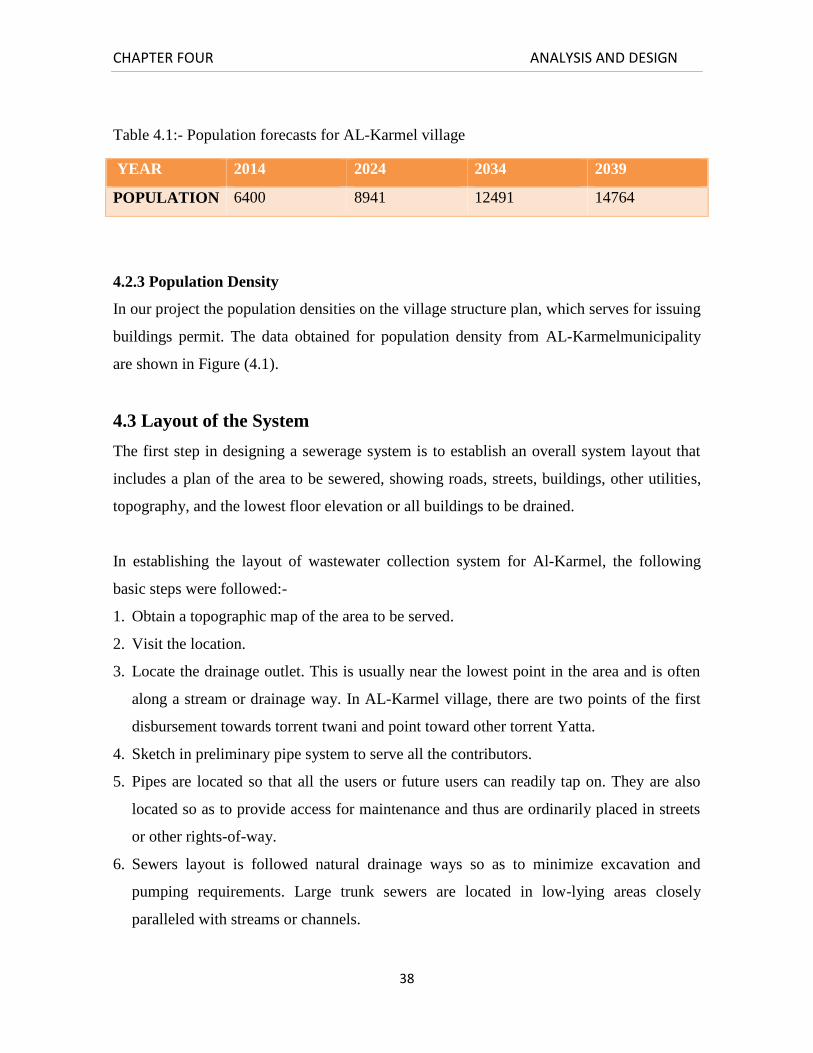
Table 4.1:- Population forecasts for AL-Karmel village
4.2.3 Population Density
In our project the population densities on the village structure plan, which serves for issuing
buildings permit. The data obtained for population density from AL-Karmelmunicipality
are shown in Figure (4.1).
4.3 Layout of the System
The first step in designing a sewerage system is to establish an overall system layout that
includes a plan of the area to be sewered, showing roads, streets, buildings, other utilities,
topography, and the lowest floor elevation or all buildings to be drained.
In establishing the layout of wastewater collection system for Al-Karmel, the following
basic steps were followed:-
1. Obtain a topographic map of the area to be served.
2. Visit the location.
3. Locate the drainage outlet. This is usually near the lowest point in the area and is often
along a stream or drainage way. In AL-Karmel village, there are two points of the first
disbursement towards torrent twani and point toward other torrent Yatta.
4. Sketch in preliminary pipe system to serve all the contributors.
5. Pipes are located so that all the users or future users can readily tap on. They are also
located so as to provide access for maintenance and thus are ordinarily placed in streets
or other rights-of-way.
6. Sewers layout is followed natural drainage ways so as to minimize excavation and
pumping requirements. Large trunk sewers are located in low-lying areas closely
paralleled with streams or channels.
YEAR 2014 2024 2034 2039
POPULATION 6400 8941 12491 14764

CHAPTER FOUR ANALYSIS AND DESIGN
39
7. Revise the layout so as to optimize flow-carrying capacity at minimum cost. Pipe
lengths and sizes are kept as small as possible, pipe slopes are minimized, and followed
the ground surface slope to minimize the depth of excavation, and the numbers of
appurtenances are kept as small as possible.
8. The pumping is avoided across drainage boundaries. Pumping stations are costly and
add maintenance problems.
The final layout of wastewater collection system of Al-Karmelvillage is illustrated in
Figure (4.2), and Figure (4.3).
Six main trunks are located on the layout.

CHAPTER FOUR ANALYSIS AND DESIGN
40

CHAPTER FOUR ANALYSIS AND DESIGN
41

CHAPTER FOUR ANALYSIS AND DESIGN
42

CHAPTER FOUR ANALYSIS AND DESIGN
43
4.4 Quantity Of Wastewater
The detailed design of sanitary sewers involves the selection of appropriate pipe sizes and
slopes to transport the quantity of wastewater expected from the surroundings and upstream
areas to the next pipe in series, which is subjected to the appropriate design constrains. The
design computations are in the example given below.
After preparing the layout of the wastewater collection system the quantity of wastewater
that the system must carry will be calculated using the data collected about the area.
Design example: Design a gravity flow sanitary sewer
Design a gravity flow main sanitary sewer for the area to outfall (line B) shown in
Figure(4.4). The following data will be collected and analyzed.
1. For current water consumption uses 70L/c.day.
2. For future water consumption uses 120L/c.day.
3. For current population
4. For future population : using the equation(4.1).
5. For population growth rate 3.4 %.
6. For design period use 25 years as a design period.
7. The wastewater calculates as 80% of the water consumption.
8. For infiltration allowance use 10% of the domestic sewerage flow.
9. Peaking factor depending on the formula :
Pf = 1.5 + (2.5/√q).
Where q = Average industrial sewage flow.
10. For the hydraulic design equation use the Manning equation with an n value of 0.01.
To simplify the computations, we use the tables.
11. Minimum pipe size: The building code specifies 200 mm (8 in) as the smallest pipe size
permissible for this situation.
12. Minimum velocity: To prevent the deposition of solids at low wastewater flows, use
minimum velocity of 0.6 m/s during the peak flow conditions.
13. Minimum cover (minimum depth of cover over the top of sewer). The minimum depth
of cover is 1.5 m.
CHAPTER FOUR ANALYSIS AND DESIGN
44
Solution :-
1. Lay out the sewer. Draw a line to represent the proposed sewer Figure (4.4).
2. Locate and number the manholes. Locate manholes at (1) change in direction, (2) change
in slope, (3) pipe junctions, (4) upper ends of sewers, and (5) intervals from 35 to 50 m
or less. Identify each manhole with a number.
3. Prepare a sewer design computation table. Based on the experience of numerous
engineers, it has been found that the best approach for carrying out sewer computations
is to use a computation table. The necessary computations of Q for the sanitary sewer
are presented in Table (4.1) , and sewer design tablesare presented in tables (4.2).The
data in the table are calculated as follow:
4. The entries in columns 1 and 2 are used to identify the line numbers and street sewer
name.
5. The entries in columns 3 through 5 are used to identify the sewer manholes, their
numbers and the spacing between each two manholes.
6. The entries in column 6 used to identify unit sewage. Unit sewage = 80% multiplied
bythe current consumption density divided area in dounm.
7. The entries in columns 7 and 8 are used tributary area, column 7 used incremental area,
column 8 used total area in dounm.
8. To calculate municipal maximum flow rates columns 9, 10, are used. Column9 is
municipal average sewage flow (unit sewage *total area), the peak factor column 10 is
calculated using equation 3.2 as: Pf = 1.5 + 2.5/ √q, where q = Average industrial
sewage flow (Column 9).
9. Column 11 used to calculate the Q max ,the value of it comes from multiply column
10* column 9. Column 12 calculate the infiltration which equal to 10% ofQaverage (10%
* column 9). Column 13 and column 15 used to show the maximum flow design which
is come from column 11+ column 1
The calculation and design tables for the wastewater collection system of Al-Karmelvillage
are shown in Appendix A.

CHAPTER FOUR ANALYSIS AND DESIGN
45

CHAPTER FOUR ANALYSIS AND DESIGN
46
CHAPTER FOUR ANALYSIS AND DESIGN
47
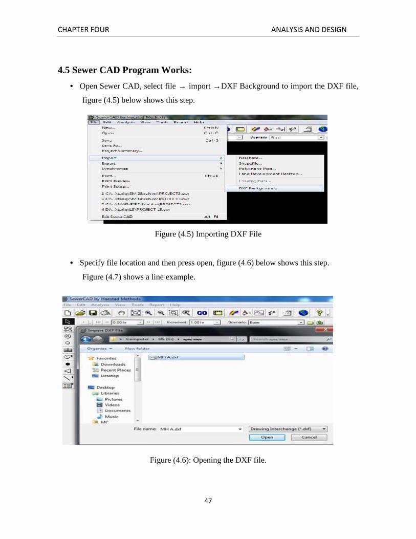
4.5 Sewer CAD Program Works:
Open Sewer CAD, select file → import →DXF Background to import the DXF file,
figure (4.5) below shows this step.
Figure (4.5) Importing DXF File
Specify file location and then press open, figure (4.6) below shows this step.
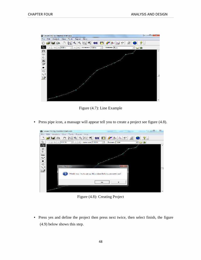
Figure (4.7) shows a line example.
Figure (4.6): Opening the DXF file.
CHAPTER FOUR ANALYSIS AND DESIGN
48
Figure (4.7): Line Example
Press pipe icon, a massage will appear tell you to create a project see figure (4.8).
Figure (4.8): Creating Project
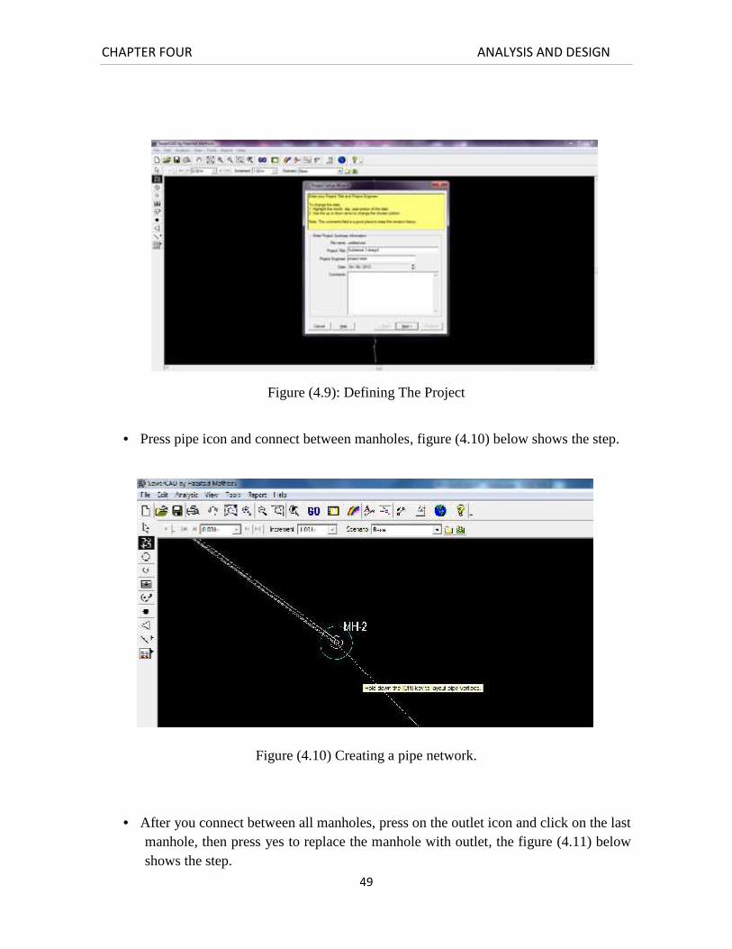
Press yes and define the project then press next twice, then select finish, the figure
(4.9) below shows this step.
CHAPTER FOUR ANALYSIS AND DESIGN
49
Figure (4.9): Defining The Project
Press pipe icon and connect between manholes, figure (4.10) below shows the step.
Figure (4.10) Creating a pipe network.
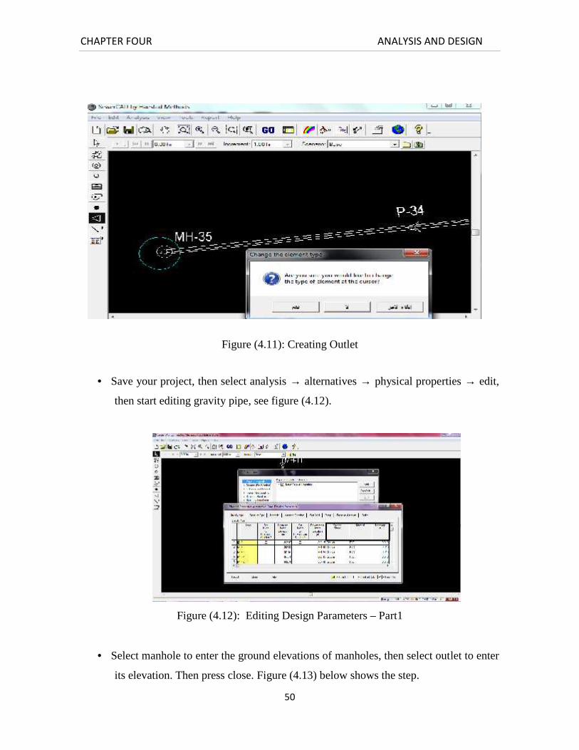
After you connect between all manholes, press on the outlet icon and click on the lastmanhole, then press yes to replace the manhole with outlet, the figure (4.11) belowshows the step.
CHAPTER FOUR ANALYSIS AND DESIGN
50
Figure (4.11): Creating Outlet
Save your project, then select analysis → alternatives → physical properties → edit,
then start editing gravity pipe, see figure (4.12).
Figure (4.12): Editing Design Parameters – Part1
Select manhole to enter the ground elevations of manholes, then select outlet to enter
its elevation. Then press close. Figure (4.13) below shows the step.

CHAPTER FOUR ANALYSIS AND DESIGN
51
Figure (4.13): Editing Design Parameters– Part2
Select sanitary (dry weather) → edit → manhole to select the type of load and to
enter the load for each manhole, figure (4.14) below shows the step.
Figure (4.14): Editing Design Parameters– Part3
After doing this for each manhole press close, then select design constrains → edit to
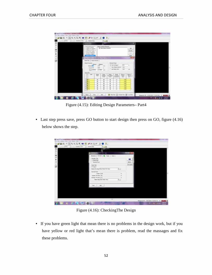
enter the design specifications, figure(4.15) below shows the step.
CHAPTER FOUR ANALYSIS AND DESIGN
52
Figure (4.15): Editing Design Parameters– Part4
Last step press save, press GO button to start design then press on GO, figure (4.16)
below shows the step.
Figure (4.16): CheckingThe Design
If you have green light that mean there is no problems in the design work, but if you
have yellow or red light that’s mean there is problem, read the massages and fix
these problems.
CHAPTER FOUR ANALYSIS AND DESIGN
53
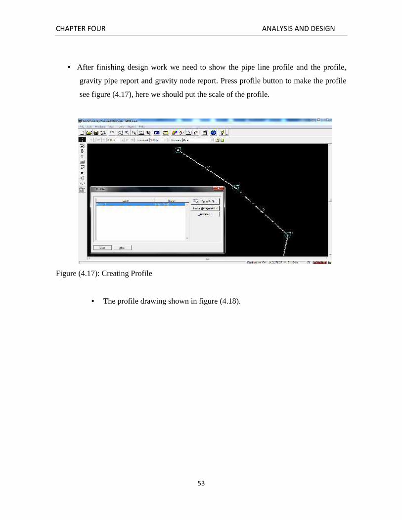
After finishing design work we need to show the pipe line profile and the profile,
gravity pipe report and gravity node report. Press profile button to make the profile
see figure (4.17), here we should put the scale of the profile.
Figure (4.17): Creating Profile
The profile drawing shown in figure (4.18).

CHAPTER FOUR ANALYSIS AND DESIGN
54
CHAPTER FOUR ANALYSIS AND DESIGN
55
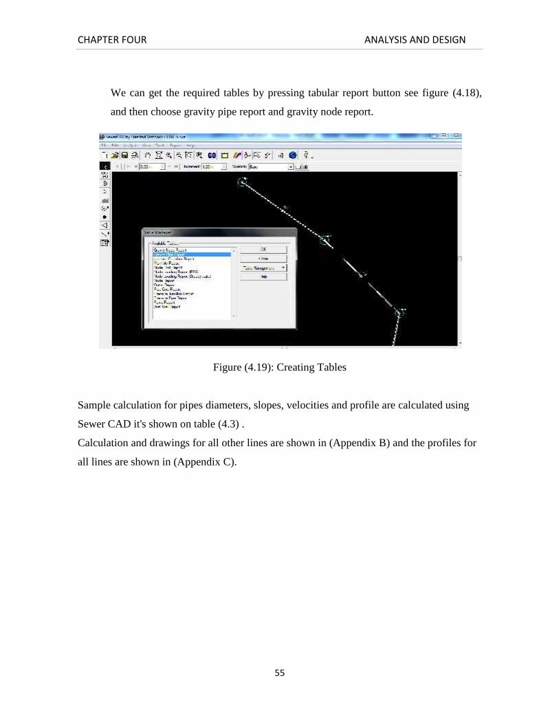
We can get the required tables by pressing tabular report button see figure (4.18),
and then choose gravity pipe report and gravity node report.
Figure (4.19): Creating Tables
Sample calculation for pipes diameters, slopes, velocities and profile are calculated using
Sewer CAD it's shown on table (4.3) .
Calculation and drawings for all other lines are shown in (Appendix B) and the profiles for
all lines are shown in (Appendix C).

CHAPTER FOUR ANALYSIS AND DESIGN
56

CHAPTER FOUR ANALYSIS AND DESIGN
57
CHAPTER FIVE BILL OF QUANTITES
58
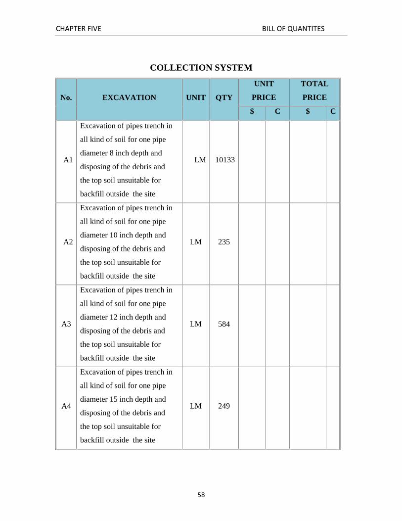
COLLECTION SYSTEM
No. EXCAVATION UNIT QTY
UNIT
PRICE
TOTAL
PRICE
$ C $ C
A1
Excavation of pipes trench in
all kind of soil for one pipe
diameter 8 inch depth and
disposing of the debris and
the top soil unsuitable for
backfill outside the site
LM 10133
A2
Excavation of pipes trench in
all kind of soil for one pipe
diameter 10 inch depth and
disposing of the debris and
the top soil unsuitable for
backfill outside the site
LM 235
A3
Excavation of pipes trench in
all kind of soil for one pipe
diameter 12 inch depth and
disposing of the debris and
the top soil unsuitable for
backfill outside the site
LM 584
A4
Excavation of pipes trench in
all kind of soil for one pipe
diameter 15 inch depth and
disposing of the debris and
the top soil unsuitable for
backfill outside the site
LM 249
CHAPTER FIVE BILL OF QUANTITES
59
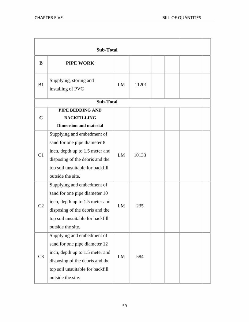
Sub-Total
B PIPE WORK
B1Supplying, storing and
installing of PVCLM 11201
Sub-Total
C
PIPE BEDDING AND
BACKFILLING
Dimension and material
C1
Supplying and embedment of
sand for one pipe diameter 8
inch, depth up to 1.5 meter and
disposing of the debris and the
top soil unsuitable for backfill
outside the site.
LM 10133
C2
Supplying and embedment of
sand for one pipe diameter 10
inch, depth up to 1.5 meter and
disposing of the debris and the
top soil unsuitable for backfill
outside the site.
LM 235
C3
Supplying and embedment of
sand for one pipe diameter 12
inch, depth up to 1.5 meter and
disposing of the debris and the
top soil unsuitable for backfill
outside the site.
LM 584
CHAPTER FIVE BILL OF QUANTITES
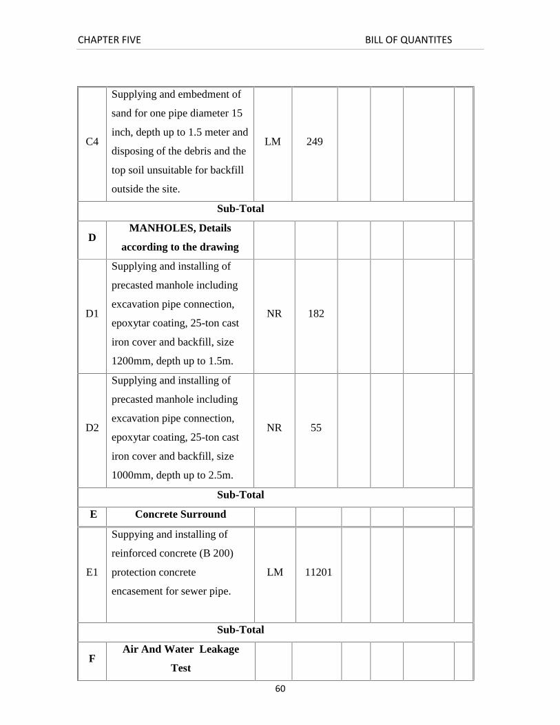
60
C4
Supplying and embedment of
sand for one pipe diameter 15
inch, depth up to 1.5 meter and
disposing of the debris and the
top soil unsuitable for backfill
outside the site.
LM 249
Sub-Total
DMANHOLES, Details
according to the drawing
D1
Supplying and installing of
precasted manhole including
excavation pipe connection,
epoxytar coating, 25-ton cast
iron cover and backfill, size
1200mm, depth up to 1.5m.
NR 182
D2
Supplying and installing of
precasted manhole including
excavation pipe connection,
epoxytar coating, 25-ton cast
iron cover and backfill, size
1000mm, depth up to 2.5m.
NR 55
Sub-Total
E Concrete Surround
E1
Suppying and installing of
reinforced concrete (B 200)
protection concrete
encasement for sewer pipe.
LM 11201
Sub-Total
FAir And Water Leakage
Test
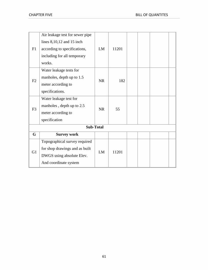
CHAPTER FIVE BILL OF QUANTITES
61
F1
Air leakage test for sewer pipe
lines 8,10,12 and 15 inch
according to specifications,
including for all temporary
works.
LM 11201
F2
Water leakage tests for
manholes, depth up to 1.5
meter according to
specifications.
NR 182
F3
Water leakage test for
manholes , depth up to 2.5
meter according to
specification
NR 55
Sub-Total
G Survey work
G1
Topographical survey required
for shop drawings and as built
DWGS using absolute Elev.
And coordinate system
LM 11201