Embed Size (px)
Citation preview

Outline
Project Update:
Heat Transfer and Internal Flowin Reciprocating Compressors
Herbert Steinruck & Thomas Mullner
Institute of Fluid Mechanics and Heat Transfer
Vienna University of Technology
Nov 6th, 2015
Herbert Steinruck & Thomas Mullner Heat Transfer and Internal Flow in Reciprocating Compressors
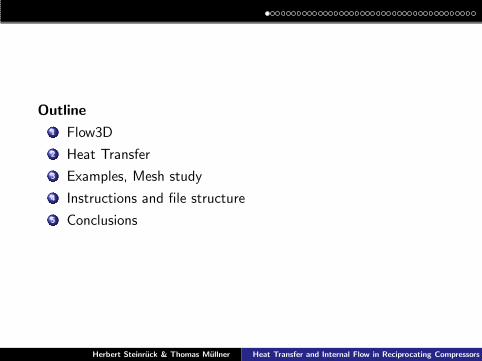
Outline
1 Flow3D
2 Heat Transfer
3 Examples, Mesh study
4 Instructions and file structure
5 Conclusions
Herbert Steinruck & Thomas Mullner Heat Transfer and Internal Flow in Reciprocating Compressors

Program family Compressor1D/2D/3D
Herbert Steinruck & Thomas Mullner Heat Transfer and Internal Flow in Reciprocating Compressors

Changes since April 2015
A bug in the “valve dynamics” has been eliminated.
The graphical representation of the flow properties on the sidewalls has been improved.
Preliminary version of the PhD-thesis of Thomas Mullner isavailable.
http://www.fluid.tuwien.ac.at/EFRC Projects
Herbert Steinruck & Thomas Mullner Heat Transfer and Internal Flow in Reciprocating Compressors

Flow 3D
Features
Flow 3D simulates the inviscid gas flow, described by theEuler equations, in the cylinder and in the valve pocketsand the motion of the valve plates.
Cylinder: structured meshmesh is characterized by th number of grid points in radialdirectiondynamic layering along cylinder axis.Solver: Roe’s method for structured grids
Unstructured mesh. A meshed reference valve pocket is given.
cone + cylinder
A posteriori calculation of heat transfer coefficients. for eachface as function of the crank angle.
Herbert Steinruck & Thomas Mullner Heat Transfer and Internal Flow in Reciprocating Compressors
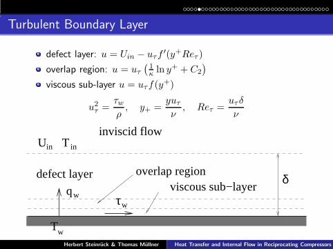
Turbulent Boundary Layer
defect layer: u = Uin − uτf′(y+Reτ )
overlap region: u = uτ(
1
κ ln y+ + C2
)
viscous sub-layer u = uτf(y+)
u2τ =τwρ, y+ =
yuτν
, Reτ =uτδ
ν
Uin
defect layerviscous sub−layer
overlap region
inviscid flow
τwwq
inT
Tw
δ
Herbert Steinruck & Thomas Mullner Heat Transfer and Internal Flow in Reciprocating Compressors
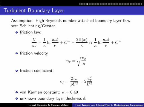
Turbulent Boundary-Layer
Assumption: High-Reynolds number attached boundary layer flow.see: Schlichting/Gersten.
friction law:
U
uτ=
1
κln
uτδ
ν+ C+ +
2Π(x)
κ≈
1
κln
uτ δ
ν+ C+
friction velocity
uτ =
√
τwρ
friction coefficient:
cf =2τwρU2
= 2u2τU2
von Karman constant: κ = 0.40
unknown boundary layer thickness δ.
Herbert Steinruck & Thomas Mullner Heat Transfer and Internal Flow in Reciprocating Compressors
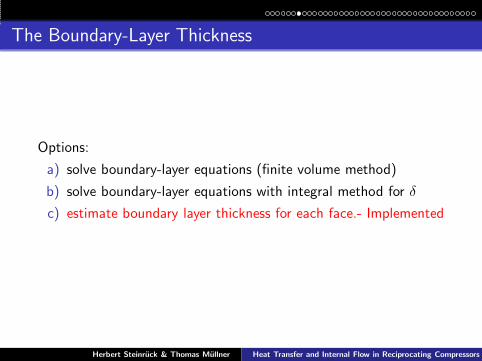
The Boundary-Layer Thickness
Options:
a) solve boundary-layer equations (finite volume method)
b) solve boundary-layer equations with integral method for δ
c) estimate boundary layer thickness for each face.- Implemented
Herbert Steinruck & Thomas Mullner Heat Transfer and Internal Flow in Reciprocating Compressors

Heat Transfer
logarithmic temperature profile in overlap region implies:
T∞ − Tw(x)
Tτ (x)=
1
κθln
uτ δ
ν+C+
θ (Pr) + Cθ(x)
friction temperature
Tτ = −qw
ρcpuτ
κθ = 0.47, Cθ(Pr) = 13.7Pr2/3 − 7.5, Pr > 0.5
Reynolds analogy
St =qw
ρcp(T − T∞)U==
cf/2
κ/κθ +√
cf2Dθ(x,Pr)
≈κθκ
cf2.
Herbert Steinruck & Thomas Mullner Heat Transfer and Internal Flow in Reciprocating Compressors

Valve Pocket
rVrz
hV
hVhK
hKx
x
y
z
valve
valve
Parameters of valve pocket:cylinder radius rZvalve radius rVcone height hKheight of valve cylinder hV
Herbert Steinruck & Thomas Mullner Heat Transfer and Internal Flow in Reciprocating Compressors

Mesh on Surface of Valve Pocket
Herbert Steinruck & Thomas Mullner Heat Transfer and Internal Flow in Reciprocating Compressors

Structured Mesh in Cylinder
grid defined by numberof cells along cylinderradius
position of valvedefined by angle ϕ ofvalve axis
ϕ
Herbert Steinruck & Thomas Mullner Heat Transfer and Internal Flow in Reciprocating Compressors

Connecting Surface
x(m)
y (m)
−0.1
−0.05
0
0.05
0.1
0.05 0.1 0.15 0.2 0.25 0.3 0.35
Surface connecting cylinder and vale pocket (blue)
Herbert Steinruck & Thomas Mullner Heat Transfer and Internal Flow in Reciprocating Compressors

Program
Euler solver on structured grid, delivered 2012, source codeavailable.
Euler solver on unstructured grid integrated in executableeuler.exe delivered April 22rd,2015
Coupling algorithm structured/unstructured mesh integratedin euler.exe delivered April 22nd,2015
A posteriori calculation of heat transfer coefficients.
No meshing tool for valve pockets is provided. Referent valvepocket is delivered. For other geometries a *.msh file has tobe created with NETGEN. But additional informationconcerning the boundary condition is needed.
GUI April 22nd,2015
Herbert Steinruck & Thomas Mullner Heat Transfer and Internal Flow in Reciprocating Compressors

Test examples
Case 1 2 3 4speed rpm 800 800 800 800ρs (kg/m3) 1 4 16 64ps (bar) 1 4 16 64pd (bar) 4 16 64 256dP (mm) 680 340 170 85# Suc./Dis. V. 5/5 4/4 3/3 2/2stroke /mm) 150 150 150 150dV (mm) 200 125 80 54
Herbert Steinruck & Thomas Mullner Heat Transfer and Internal Flow in Reciprocating Compressors

Valve lift, Cases 1 & 2
Herbert Steinruck & Thomas Mullner Heat Transfer and Internal Flow in Reciprocating Compressors

Valve lift, Cases 3 & 4
Herbert Steinruck & Thomas Mullner Heat Transfer and Internal Flow in Reciprocating Compressors
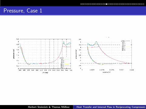
Pressure, Case 1
Herbert Steinruck & Thomas Mullner Heat Transfer and Internal Flow in Reciprocating Compressors

Pressure at opening of DVs
Herbert Steinruck & Thomas Mullner Heat Transfer and Internal Flow in Reciprocating Compressors
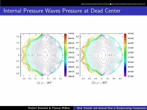
Internal Pressure Waves Pressure at Dead Center
Herbert Steinruck & Thomas Mullner Heat Transfer and Internal Flow in Reciprocating Compressors

Internal Pressure Waves Pressure at Dead Center
Herbert Steinruck & Thomas Mullner Heat Transfer and Internal Flow in Reciprocating Compressors

Internal Pressure Waves Pressure at Dead Center
Herbert Steinruck & Thomas Mullner Heat Transfer and Internal Flow in Reciprocating Compressors

Velocity Magnitude at Piston
Herbert Steinruck & Thomas Mullner Heat Transfer and Internal Flow in Reciprocating Compressors

Velocity Magnitude at Piston
Herbert Steinruck & Thomas Mullner Heat Transfer and Internal Flow in Reciprocating Compressors

Velocity Magnitude at Piston
Herbert Steinruck & Thomas Mullner Heat Transfer and Internal Flow in Reciprocating Compressors

Maximal Mach number 800 rpm
Herbert Steinruck & Thomas Mullner Heat Transfer and Internal Flow in Reciprocating Compressors

Maximal Mach number 1200 rpm
Herbert Steinruck & Thomas Mullner Heat Transfer and Internal Flow in Reciprocating Compressors

Velocity at Piston CA=420◦
Herbert Steinruck & Thomas Mullner Heat Transfer and Internal Flow in Reciprocating Compressors

Pressure at piston CA=306◦
Herbert Steinruck & Thomas Mullner Heat Transfer and Internal Flow in Reciprocating Compressors

Temperature at side wall CA=504◦
temperature, CA=504°
−0.4−0.3−0.2−0.1 0 0.1 0.2 0.3 0.4−0.4−0.3
−0.2−0.1
0 0.1
0.2 0.3
0.4 0
0.02 0.04 0.06 0.08 0.1
0.12 0.14
340 345 350 355 360 365 370
Herbert Steinruck & Thomas Mullner Heat Transfer and Internal Flow in Reciprocating Compressors
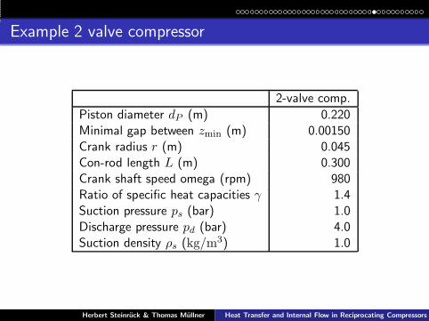
Example 2 valve compressor
2-valve comp.
Piston diameter dP (m) 0.220Minimal gap between zmin (m) 0.00150Crank radius r (m) 0.045Con-rod length L (m) 0.300Crank shaft speed omega (rpm) 980Ratio of specific heat capacities γ 1.4Suction pressure ps (bar) 1.0Discharge pressure pd (bar) 4.0Suction density ρs (kg/m3) 1.0
Herbert Steinruck & Thomas Mullner Heat Transfer and Internal Flow in Reciprocating Compressors

Mesh refinement
A new reference mesh with halves all edges has been created forcomparison, not delivered.
cells along radius mesh in valve pocket comp. time CA = 420◦
15 standard 10 h 23 min30 standard sing. at CA = 9◦
30 fine 81 h 48 min
Herbert Steinruck & Thomas Mullner Heat Transfer and Internal Flow in Reciprocating Compressors

Pressure
suction valve
discharge valve
50000
100000
150000
200000
250000
300000
350000
400000
450000
500000
0 50 100 150 200 250 300 350 400 450
pres
sure
[Pa]
fine mesh
crank angle [°]
standard mesh
fine mesh, standard mesh
Herbert Steinruck & Thomas Mullner Heat Transfer and Internal Flow in Reciprocating Compressors

Pressure difference
fine meshstandard mesh
−30000
−20000
−10000
0
10000
20000
30000
40000
50000
0 50 100 150 200 250 300 350 400 450
pres
sure
diff
eren
ce: s
uctio
n−di
scha
rge
[Pa]
crank angle [°]
fine mesh, standard mesh
Herbert Steinruck & Thomas Mullner Heat Transfer and Internal Flow in Reciprocating Compressors

Vertical velocity CA=100◦ - Intake
’Side100.txt’ u 4:5:6:11
−0.15−0.1
−0.05 0
0.05 0.1
0.15
−0.15−0.1
−0.05 0
0.05 0.1
0.15
0 0.01 0.02 0.03 0.04 0.05 0.06
−60−40−20 0 20 40 60
’Side100.txt’ u 4:5:6:11
−0.15−0.1
−0.05 0
0.05 0.1
0.15
−0.15−0.1
−0.05 0
0.05 0.1
0.15
0 0.01 0.02 0.03 0.04 0.05 0.06
−60−40−20 0 20 40 60
fine mesh standard mesh
Grid dependence of flow field ⇒ Grid dependence of heat transfercoefficient during intake!
Herbert Steinruck & Thomas Mullner Heat Transfer and Internal Flow in Reciprocating Compressors
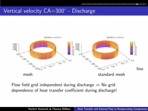
Vertical velocity CA=300◦ - Discharge
’Side300.txt’ u 4:5:6:11
−0.15−0.1
−0.05 0
0.05 0.1
0.15
−0.15−0.1
−0.05 0
0.05 0.1
0.15
0 0.005 0.01
0.015 0.02
0.025
−30−25−20−15−10−5 0 5
’Side300.txt’ u 4:5:6:11
−0.15−0.1
−0.05 0
0.05 0.1
0.15
−0.15−0.1
−0.05 0
0.05 0.1
0.15
0 0.005 0.01
0.015 0.02
0.025
−30−25−20−15−10−5 0 5
finemesh standard mesh
Flow field grid independent during discharge ⇒ No griddependence of heat transfer coefficient during discharge!
Herbert Steinruck & Thomas Mullner Heat Transfer and Internal Flow in Reciprocating Compressors

Heat transfer coefficients
fine meshstandard mesh
head
side wall
piston
0
50
100
150
200
250
300
350
400
0 50 100 150 200 250 300 350 400 450
heat
tran
sfer
coe
ffici
ent [
W/m
^2 K
]
crank angle [°] fine mesh,standard mesh
HTCs depend on grid during intake, grid independent otherwise.
Herbert Steinruck & Thomas Mullner Heat Transfer and Internal Flow in Reciprocating Compressors

File Structure
GUI: Compressor3D.exe resides in ExecutingFiles.It creates the files InputCylinder.txt Input-Valves.txt and puts them into the right place.It creates the Output directory Casexxx and itssub-directories.It calls euler.exe which writes the output datain the corresponding directories.
Output.txt Valve data and some global data forevery times step.sidennn.txt, pistonnnn.txt, headnnn.txt veloc-ity, density pressure for each surface cell atcrank angle nnn.alpha on HSP.txt Heat transfer coefficients forhead, piston side wall as function of crank angle.
Casexxx
headnnn.txt
pistonnnn.txt
sidennn.txt
side
piston
head
Output.txt
InputCylinder.txt
InputValves.txt
alpha_on_HPS.txt
ExecutingFiles
Input data
Executing Files
Compreesor3D.exe
euler.exe
InputCylinder.txt
InputValves.txt
reference_valve_pocket.msh
Casexxx.msh Results
Herbert Steinruck & Thomas Mullner Heat Transfer and Internal Flow in Reciprocating Compressors

Instructions
Download setupComp3D.exe fromhttp://cddlab2.fluid.tuwien.ac.at/EFRC/Compressor3D/Version04
Install Compressor3D by executing setup3D.exe
Start Compressor3D: (Switch toCompressor3D/ExecutingFiles and run Comp3D.exe)
Define the Compressor data or read an the Input data files (2Files needed: InputCylinder.txt, InputValves.txt)
Define a case name and run the program (11 hours for twocomplete cycles on my laptop).
Display the data
The data can be accessed in the files Output.txt andheadnnn.txt, sidennn.txt, pistonnnn.txt (see file structure)
Herbert Steinruck & Thomas Mullner Heat Transfer and Internal Flow in Reciprocating Compressors

Conclusions
Flow in cylinder Flow in valve cage Heat transfer
proposal
inviscid 3D inviscid 1D boundary-layer along cylin-der walls
delivered
inviscid 3D inviscid 3D boundary-layer along cylin-der walls
File download:
http://www.fluid.tuwien.ac.at/EFRC Projects
Herbert Steinruck & Thomas Mullner Heat Transfer and Internal Flow in Reciprocating Compressors
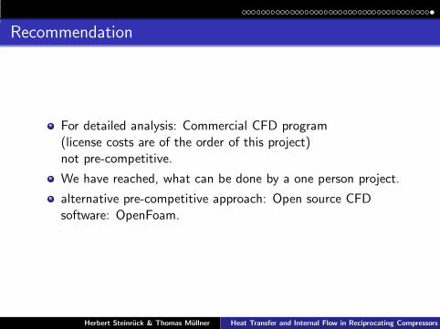
Recommendation
For detailed analysis: Commercial CFD program(license costs are of the order of this project)not pre-competitive.
We have reached, what can be done by a one person project.
alternative pre-competitive approach: Open source CFDsoftware: OpenFoam.
Herbert Steinruck & Thomas Mullner Heat Transfer and Internal Flow in Reciprocating Compressors


![Conjugate Heat Transfer in Ribbed Cylindrical Channels€¦ · rate of heat transfer [8]. To increase the heat transfer with minimal friction in compact heat exchangers, the internal](https://img.pdfslide.net/doc/110x75/605d788731bb5b1cbb1e3e7e/conjugate-heat-transfer-in-ribbed-cylindrical-channels-rate-of-heat-transfer-8.jpg)


![Comparative Analysis of Fin Heat Transfer Using Simulation ... … · the nonlinear heat transfer equation [3] in the longitudinal fin with temperature-dependent internal heat generation](https://img.pdfslide.net/doc/110x75/5e226f60aeab533e5551a0ea/comparative-analysis-of-fin-heat-transfer-using-simulation-the-nonlinear.jpg)