Embed Size (px)
Citation preview

Team #11 Embodiment Design Report
MECH 4010 & 4015Design Project I
FALL DESIGN REPORT
Magnetic Levitation Demonstration ApparatusTeam #11
Ajay PuppalaFuyuan Lin
Marlon McCombieXiaodong Wang
Submitted: December 3, 2013
MECH4010/4015 Magnetic Levitation Demonstration Apparatus Page 1 of 51

Team #11 Fall Term Report
Table of Contents
List of Figures..................................................................................................................................4
List of Tables...................................................................................................................................4
1. Project Information.................................................................................................................5
1.1. Project Title.....................................................................................................................51.2. Project Customer.............................................................................................................51.3. Group Members...............................................................................................................51.4. Useful Definitions and Acronyms...................................................................................5
2. Executive Summary...............................................................................................................6
3. Background and Context........................................................................................................7
3.1. Background and Overall Objective.................................................................................73.2. Requirements...................................................................................................................8
4. Summary of Design Alternatives...........................................................................................9
5. System Architecture.............................................................................................................11
5.1. Selected Design.............................................................................................................115.2. Subsystems / Components.............................................................................................11
6. Levitation: Electromagnet....................................................................................................14
6.1. Component Description.................................................................................................146.2. Component Design........................................................................................................14
7. System Feedback: Sensor.....................................................................................................17
7.1. Component Description.................................................................................................17
8. Microcontroller Unit.............................................................................................................18
8.1. Component Description.................................................................................................18
9. Signal Conditioning : Control Circuit..................................................................................20
9.1. Component Description.................................................................................................209.2. Component Design........................................................................................................20
10. User Interface.......................................................................................................................23
10.1. Component Description.................................................................................................2310.2. Component Design........................................................................................................23
MECH4010/4015 Magnetic Levitation Demonstration Apparatus Page 2 of 51

Team #11 Fall Term Report
11. Feasibility & Risk Assessment.............................................................................................25
12. Testing and Verification Plan...............................................................................................26
13. Cost Estimates & Budget.....................................................................................................27
14. Progress Report....................................................................................................................29
15. Future Considerations...........................................................................................................31
15.1. Preliminary Apparatus Design......................................................................................31
16. Project Management Plan.....................................................................................................33
16.1. Organizational Responsibilities.....................................................................................3316.2. Work Breakdown Structure...........................................................................................3416.3. Schedule........................................................................................................................4216.4. Specialized Facilities and Resources.............................................................................44
16.4.1. Facilities..............................................................................................................4416.4.2. Additional Advisors............................................................................................44
17. References............................................................................................................................45
Appendix A Simulink block diagram for electromagnetic levitation............................................i
Appendix C Sample Programs.......................................................................................................iii
Appendix B Design Calculations for Electromagnet....................................................................v
MECH4010/4015 Magnetic Levitation Demonstration Apparatus Page 3 of 51

Team #11 Fall Term Report
List of Figures
Figure 1 Design Alternatives.....................................................................................................9Figure 2 Single electromagnet design with Hall Effect sensor.................................................11Figure 3 General Schematic of demonstration device...............................................................12Figure 4 Functional block diagram for the magnetic levitation apparatus................................13Figure 5 Magnetic field generated by the current carrying coil (courtesy of
superconductors.solidchem.net)..................................................................................14Figure 6 Picture of Hall Effect Sensor......................................................................................17Figure 7 Picture of Arduino UNO.............................................................................................18Figure 8 Electromagnetic coil driving circuit (Mekonikuv).....................................................21Figure 9 Sensor with amplifier circuit (Mekonikuv).................................................................21Figure 10 Arduino Simulink block diagram example................................................................24Figure 11 Hall Effect sensor output with and without permanent magnet (object)...................29Figure 12 Actual control circuit.................................................................................................30Figure 13 Proposed Apparatus design.........................................................................................32Figure 14 Fall term work breakdown structure...........................................................................35Figure 15 Research work breakdown structure...........................................................................36Figure 16 Product design work breakdown structure..................................................................37Figure 17 Concept evaluation breakdown structure....................................................................38Figure 18 Fall term WBS critical path chart...............................................................................39Figure 19 Winter term work breakdown structure......................................................................40Figure 20 Winter term WBS critical path chart..........................................................................41Figure 21 Simulink block diagram for electromagnetic levitation................................................i
List of Tables
Table 1 Selected criteria (highlighted) for physical apparatus design.......................................9Table 2 Arduino UNO specification summary........................................................................19Table 3 Component and materials cost breakdown.................................................................27Table 4 Required engineering expertise...................................................................................33Table 5 Allocation of team responsibilities.............................................................................34Table 6 Summary of project tasks for fall 2013 term..............................................................42Table 7 Breakdown of remaining hours of work for the winter break....................................43Table 8 Summary of project tasks for winter 2013 term.........................................................43Table 9 Design calculations for electromagnet..........................................................................v
MECH4010/4015 Magnetic Levitation Demonstration Apparatus Page 4 of 51

Team #11 Fall Term Report
1. Project Information
1.1. Project TitleMagnetic Levitation Demonstration Apparatus
1.2. Project CustomerDr Robert BauerProfessorMechanical Engineering DepartmentDalhousie University
1.3. Group MembersAjay Puppala email: [email protected] Lin email: [email protected] McCombie email:[email protected] Wang email: [email protected]
1.4. Useful Definitions and AcronymsPID - Proportional Integral Derivative ControlP - Proportional ControlPI - Proportional Integra ControlGUI - Graphical User InterfacePC - Personal ComputerPPE - Personal Protective EquipmentPCB - Printed Circuit BoardMagLev - Magnetic LevitationEM - ElectromagnetMCU - Microcontroller UnitPWM - pulse width modulationI/O - Input/outputEOPD - Electro-Optical Proximity DetectorRISC - Reduced instruction set computingCMOS - Complementary metal-oxide semiconductorAVR - no meaningISCP - In-circuit serial programmingEEPROM - Electrically Erasable Programmable Read-Only MemorySRAM - Static random-access memoryDC - Direct currentAC - Alternating currentWBS - Work Breakdown Structure
MECH4010/4015 Magnetic Levitation Demonstration Apparatus Page 5 of 51
Team #11 Embodiment Design Report
2. Executive Summary
This report outlines the design process of the Magnetic Levitation Demonstration
Apparatus through the fall term of the final year Mechanical Engineering design project at
Dalhousie University. The contents of the document include project requirements, design
alternatives, subsystems for the selected design, current progress, future considerations,
testing plan, updated budget, technical drawings, and finally a plan of action for the winter
term.
The goal of our project is to design and build a portable and compact device that
magnetically levitates an object to demonstrate different control design theories presented in
MECH4900 Systems II. The theories must be tested using Mathworks Simulink. A Graphical User
Interface (GUI) in Simulink is desired so users can interact with the system conveniently.
The group made significant progress during the term in building a prototype for magnetic
levitation. A coil driver circuit and sensory signal conditioning circuit were built (using an existing
example) and were successfully tested using the Arduino; however, levitation has not been
achieved. The group is confident to achieve levitation in a day or two of working on the code
necessary to control the Arduino to perform levitation. A Simulink block diagram was developed
using existing diagrams for magnetic levitation. Moving forward, the group has planned to complete
the necessary programming for levitation and continue work on the Simulink block diagram during
the winter break. Additionally, materials required for the prototype will be ordered as most of them
were sourced from Dr. Bauer, our project supervisor, and Mr. Jonathan MacDonald, the Electrician
for the Mechanical Engineering department at the university.
The work breakdown structure (WBS) and corresponding schedule was completed and is
attached to this document in the Project Management section. The group has a very good
understanding of the project progress and tasks ahead.
MECH4010/4015 Magnetic Levitation Demonstration Apparatus Page 6 of 51

Team #11 Fall Term Report
3. Background and Context
3.1. Background and Overall Objective
Demonstrations provide the opportunity for students to predict theoretical outcomes of real
life applications of course material which in turn allow them to confirm their initial understanding
of those same concepts. Where students are not able to confirm their understanding of a given
concept, the instructor can use demonstrations to discuss any differences between their initial
understanding and what the demonstration actually shows. Visual demonstrations help to bridge
the gap between the applications of course material and what is being taught in class; this can be
illustrated using graphical analyses of the concepts to represent real life examples. Consequently,
the purpose of this project is to design a magnetic levitation demonstration apparatus or the
purpose of demonstrating the different design control theories presented in the Mechanical
Engineering course MECH4900-Control Systems II. The apparatus is intended to serve as a platform
for a real-life example of the implementation of control theories such as proportional, derivative,
integral, and a combination of the three control methods. Control Systems II not only makes use of
the design theories mentioned but also includes the graphical representation and analyses of these
control theory responses. The use of a live demonstration will provide real-life feedback of the
manipulation of control theories so that students may see, first-hand, the application of the course
material. Although diagrams may be a step further to having a better visual understanding of a
concept, a demonstration that produces live feedback vastly improves the delivery of course
material. This concept is similar to a salesman increasing the appeal of a product by showing its
many uses through infomercials; i.e. demonstrations of the basic use of a known concept (e.g.
blending with the Magic Bullet). The only difference for course material from this analogy is that
the concepts being taught are new to students and may not be initially understood from course
lectures.
Thus, the scope of our project is to design and build a portable and compact device that
magnetically levitates an object to demonstrate different control design theories presented in
MECH4900 Systems II.
MECH4010/4015 Magnetic Levitation Demonstration Apparatus Page 7 of 51

Team #11 Fall Term Report
3.2. Requirements Purpose
o Build portable demonstration device
o Magnetically levitate object
o Demonstrate theories presented in MECH4900(4905) Control Systems II
Visual Requirements
o Shall be viewable from the back of a classroom (15-20ft) and/or using cameras
o Levitate object for range of approximately 15 mm
User Convenience & Safety
o Easy to carry; i.e. lightweight
Levitated object will be approximately 30mm in diameter and weigh no
more than 10 g
Apparatus shall be no more than 1.5 kg (or about the weight of a standard
laptop)
No steel toed boots shall be required for transportation of apparatus (i.e.
there shall be no crushing potential to user’s feet)
o Apparatus shall pose no electrical risk to user
Power Requirements
o Conventional 120 VAC input from a conventionally purchased (and thus
replaceable) power supply
User Interactive Requirements
o User shall interact with the device using a graphical user interface (GUI)
o Device shall be ready to operate once plugged into PC
Demonstrative Requirements
o Comparison of desired, simulated, manipulated, and measured controller variables
o Nyquist plots
o Bode diagrams
o Lag, lead, lag-lead compensation techniques
o P, PI, PID control
Miscellaneous
o Shall be an active controller
o Budget no more than $1,000
MECH4010/4015 Magnetic Levitation Demonstration Apparatus Page 8 of 51

Team #11 Fall Term Report
4. Summary of Design Alternatives
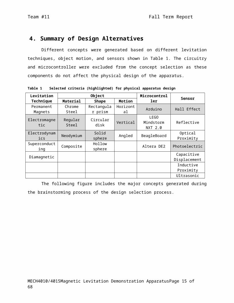
Different concepts were generated based on different levitation techniques, object motion,
and sensors shown in Table 1. The circuitry and microcontroller were excluded from the concept
selection as these components do not affect the physical design of the apparatus.
Table 1 Selected criteria (highlighted) for physical apparatus design
Levitation Technique
ObjectMicrocontroller Sensor
Material Shape MotionPermanent
MagnetsChrome Steel
Rectangular prism
Horizontal Arduino Hall Effect
Electromagnetic Regular Steel Circular disk VerticalLEGO Mindstorm
NXT 2.0Reflective
Electrodynamics Neodymium Solid sphere Angled BeagleBoard Optical ProximitySuperconducting Composite Hollow sphere Altera DE2 Photoelectric
DiamagneticCapacitive
DisplacementInductive ProximityUltrasonic
The following figure includes the major concepts generated during the brainstorming
process of the design selection process.
Figure 1 Design Alternatives
The first concept is the single electromagnet with a Hall Effect sensor. This design is simple
and easy to configure. A major disadvantage of this design is that it the Hall Effect sensor senses
magnetic field strength which must be converted to a position for the levitated object. To
MECH4010/4015 Magnetic Levitation Demonstration Apparatus Page 9 of 51

Team #11 Fall Term Report
compensate for this problem, a photoelectric sensor can be used (concept 2) in which case the
stand design has to be changed to accommodate LED bulbs and an associated photoelectric sensor.
An underlining problem for both the first and second concepts is that the field strength may not be
sufficient to levitate the object in the desired range (see requirements).
Consequently, the next few design alternatives were proposed to allow a greater magnetic
field strength for the system. Concept 3 shows two electromagnets which could possibly extend the
range of the magnetic levitation. However, this design may pose other problems in terms of stability
and obtaining levitation since two electromagnets must be coordinated to achieve levitation.
Alternative four was proposed to improve stability by using electrodynamic levitation instead of
electromagnetic with multiple coils in a parallel configuration. The major cause for concern for
concept four is that the visibility of levitation may be reduced due to obstruction by the coils. Also,
the total cost for building the device would increase substantially considering the number coils
used in the design.
Concept five, a MagLev Track Design, is different from the latter designs. For the MagLev
Track design, the levitating disk is properly constrained to move along a vertical path. This implies
proper stability for motion of the object and levitation can be seen through the gaps between the
electromagnets. The demonstrative requirements could jeopardized as it may seem that the disk is
supported by the tracks. Additionally, it would cost more money to build compared to other design
due to the increased material needed for the tracks.
The last concept considered for design alternatives is Concept six, a Torodial coil design.
The object is levitated in a circular transparent tube with electromagnets at regular intervals. When
power is supplied to the magnets, the object is expected to spin depending on the force of attraction
and/or repelled by the magnets. The major trouble with this design is actually building and testing
the device. The complexity of the design is too high and if it can be done it will be very impressive.
All the concepts consider for design alternatives were evaluated using a rubric that is
presented in the Appendix. The basic requirements are weighted the most for selection criteria
compared to the parts, design, and cost assessment. Based on the evaluation, it was decided that
the single coil electromagnetic sensor is best for the design. Consequently, concepts one
and two were determined to be the best solutions.
MECH4010/4015 Magnetic Levitation Demonstration Apparatus Page 10 of 51

Team #11 Fall Term Report
5. System Architecture
5.1. Selected DesignIt was decided to move forward with a single coil electromagnetic source as shown in Figure 2,
using a Hall Effect sensor. A single coil electromagnet was chosen for the design since it is more
simplistic to build and test and has been used for electromagnetic levitation before (Mekonikuv
Blog, Lieberman). The Hall Effect sensor was chosen mainly because it was used in the example
used for the coil driving and sensor amplifying circuit by Lieberman. It is important to note that all
the above components were also chosen because of their low cost.
Figure 2 Single electromagnet design with Hall Effect sensor
5.2. Subsystems / Components
Figure 3 shows a general schematic of the system components needed to build a functional
magnetic levitation demonstration apparatus based on the specified requirements.
MECH4010/4015 Magnetic Levitation Demonstration Apparatus Page 11 of 51

Team #11 Fall Term Report
Figure 3 General Schematic of demonstration device
For magnetic levitation to be achieved for the purpose of demonstrating various design
techniques presented in Control Systems II, a user would need to vary a magnetic field which in
theory should vary the position of a levitating object. A varying magnetic field is most commonly
achieved by a non-permanent magnet or more specifically by using an electromagnet.
Electromagnets allows for a varying input current to be applied to them for the purpose of
manipulating a magnetic field and hence the position of a magnetically levitating object. In Figure 3,
the electromagnet is represented by the magnetic source.
It is required to use MATLAB/Simulink to design controllers for demonstration of the
different control theories presented in Systems II. The designed controllers must then be able to
control the apparatus to achieve the desired control being demonstrated; this is achieved through
the microcontroller unit. Using MATLAB/Simulink a user will be able to communicate with the
microcontroller which would then execute the desired I/O signals to perform the desired control of
the electromagnetic field. Once this communication is achieved, some form of feedback becomes
necessary to inform the designed controller of the output result of its input to the electromagnet. A
sensor will be responsible for providing this feedback. Generally, the microcontroller would be
instructed, by the user/designed controller through MATLAB/Simulink, to retrieve necessary data
from the sensor during the implementation of the control demonstration. The microcontroller then
sends this information back to MATLAB/Simulink where it is presented to the user in graphical
form.
The amount of current and voltage required to power an electromagnet (usually 12V) to
levitate a reasonably visible object is more than the amount that can be supplied by a
microcontroller unit which usually gives a maximum output voltage of 5V. Consequently, an
external power supply is required. Therefore, before any input is given to the electromagnet or any
data is retrieved from the sensor, some form of signal conditioning is required to:
MECH4010/4015 Magnetic Levitation Demonstration Apparatus Page 12 of 51
Team #11 Fall Term Report
1. Maintain a relatively steady magnetic field
2. Sensitize system feedback
3. Protect the system and the user from electrical harm
Signal conditioning is handled by the circuitry. In order to maintain a steady magnetic field, a steady
input current must be supplied to the electromagnet. In addition, a more sensitive sensor would
produce a more sensitive feedback on the position of the levitating object. Finally, it is required to
design and build a safe-to-use apparatus; thus, it is required to have protective measures designed
into the systems signal transmission so that users are protected from electrical injury and the
apparatus is protected from electrical damage. The next figure summarizes the required
functionality of the operating device. The final design shall meet these major functionality
requirements.
Figure 4 Functional block diagram for the magnetic levitation apparatus
In addition, an Arduino UNO was used for the project because it was one of two readily available
microcontrollers for testing from the University. The other microcontroller was a LEGO
Minsdstorms NXT 2.0 but this microcontroller was decided against because it is more expensive
than the Arduino. The requirements of the microcontroller are minimal; i.e. not many I/O digital or
analog pins are required for any of the design alternatives presented. The required I/O capabilities
of the microcontroller can be achieved with either the Arduino or LEGO NXT.
MECH4010/4015 Magnetic Levitation Demonstration Apparatus Page 13 of 51
INPUT
Control method generated in MATLAB/Simulink
Current supplied to the magnetic coil
PROCESSExecute the control method from
MATLAB/Simulink through microcontroller
Maintain the desired position of a levitated object using position
feedback from sensor(s)
Record data from sensor(s) over a specified duration of the
demostration
OUTPUT
Position feedback of object from sensor
Graphical display of recorded data

Team #11 Fall Term Report
6. Levitation: Electromagnet
6.1. Component DescriptionElectromagnets are a type of magnet that can generate a magnetic field when current is
allowed to pass through it (see figure 4). The field induces flux on ferromagnetic material that is
introduced in the field. It is important to design an electromagnet that would meet the
requirements of the project in terms of range of levitation of the object, required flux to hold the
object in place, duration of levitation, and power supply limitations. Off the shelf electromagnets
are available; however, they are designed and used for different purposes. Finding the right one and
testing it would be cumbersome. Instead, designing an electromagnet based on the required
strength of the magnetic field is suitable and most appropriate for this project.
Figure 5 Magnetic field generated by the current carrying coil (courtesy of superconductors.solidchem.net)
6.2. Component DesignThe electromagnet design is based on a few assumptions which are listed as follows:
The magnetic ball is subjected to gravitational and magnetic forces
air friction and damping effects are legible
The air gap range is assumed to be between 30 to 50mm
The electromagnet core diameter is 30mm and its length is 100mm
The number of turns in the solenoid is 1000 turns
The diameter of the levitated object is 25mm
The length of solenoid is 100mm and
The stacking factor is 0.9
MECH4010/4015 Magnetic Levitation Demonstration Apparatus Page 14 of 51
Team #11 Fall Term Report
Based on assumptions made on the diameter of the levitating object as well as the density of steel, it
is easy to get the volume as well as the mass of levitating objects. Air gap is an important parameter
that will determine the amount of current that goes through the electromagnet and the force
required to levitate the magnetic ball. Since the air gap is assumed, the force balance on the object is
Fmagnet=Fgravity=mg=0.01kg∗9.81ms2 =0.981kg, where m is the mass of the object, g is
gravitational acceleration. Pole area is calculated as A=0.0017m2 with the magnetic force, the
magnetic field needed to levitate the object can be calculated by using the following equation:
B= 2√ 2∗μo∗FmagnetA
=2√ 2∗(4∗π∗10−7)∗0.981
0.0017=0.0027wb /m2
where F is the magnetic force (N), B is the magnetic field generated by the electromagnet (T), A is
the pole area of the electromagnet (m2), and µo is the permeability of free space for air it is always
4 x 10π -7 HM-1. The calculation is to estimate the maximum magnetic field needed. Another factor is
that the magnetic field B saturated at certain value, which is approximately 1.6T. This will set a limit
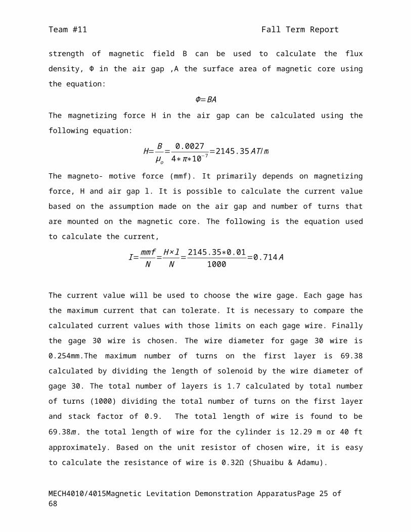
on the maximum force per unit core area that the electromagnet can exert The strength of magnetic
field B can be used to calculate the flux density, Ф in the air gap ,A the surface area of magnetic core
using the equation:
Φ=BA
The magnetizing force H in the air gap can be calculated using the following equation:
H= Bμo
= 0.00274∗π∗10−7 =2145.35 AT /m
The magneto- motive force (mmf). It primarily depends on magnetizing force, H and air gap l. It is
possible to calculate the current value based on the assumption made on the air gap and number of
turns that are mounted on the magnetic core. The following is the equation used to calculate the
current,
I=mmfN
=H ×lN
=2145.35∗0.011000
=0.714 A
The current value will be used to choose the wire gage. Each gage has the maximum current that
can tolerate. It is necessary to compare the calculated current values with those limits on each gage
wire. Finally the gage 30 wire is chosen. The wire diameter for gage 30 wire is 0.254mm.The
maximum number of turns on the first layer is 69.38 calculated by dividing the length of solenoid
by the wire diameter of gage 30. The total number of layers is 1.7 calculated by total number of
turns (1000) dividing the total number of turns on the first layer and stack factor of 0.9. The total
MECH4010/4015 Magnetic Levitation Demonstration Apparatus Page 15 of 51

Team #11 Fall Term Report
length of wire is found to be 69.38m . the total length of wire for the cylinder is 12.29 m or 40 ft
approximately. Based on the unit resistor of chosen wire, it is easy to calculate the resistance of
wire is 0.32Ω (Shuaibu & Adamu).
MECH4010/4015 Magnetic Levitation Demonstration Apparatus Page 16 of 51

Team #11 Fall Term Report
7. System Feedback: Sensor
7.1. Component DescriptionThe Hall Effect sensor was chosen for the project as it is a commonly used magnetic sensor
found most commonly in motor vehicles to detect the position of rotating parts. Figure 6 shows an
example of a Hall Effect sensor.
Figure 6 Picture of Hall Effect Sensor
The Hall Effect sensor is an analog position sensor that operates by generating a steady electrical
output, when excited, which can be altered to a higher state when a magnetic field is placed near its
body (Honeywell SS49 datasheet). The Hall Effect sensor output voltage intensifies with decreasing
distance between its body and a magnetic source. The Hall Effect sensor is an important component
of the apparatus as it is responsible for position sensing of the levitating object and thus, for
providing position feedback to designed controllers.
MECH4010/4015 Magnetic Levitation Demonstration Apparatus Page 17 of 51

Team #11 Fall Term Report
8. Microcontroller Unit
8.1. Component DescriptionThe selected Microcontroller for the project is the Arduino UNO (Figure 7). The Arduino UNO is
based on the ATmega328 (Arduino UNO webpage), a low-power CMOS 8-bit microcontroller based
on AVR enhanced RISC architecture. The ATmega328 is designed to optimize power consumption
versus processing speed (ATmega238 datasheet). The Arduino UNO consists of 14 digital I/O pins
(including six pins that can be used as PWM outputs), six analog inputs, a 16 MHz ceramic
resonator, a USB connection, a power jack, an ICSP header, and a reset button. Additionally, it can
be powered through USB or with an AC-to-DC adapter or battery. Unlike preceding boards, the UNO
uses Atmega16U2 programmed as a USB-to-serial. Table 2 summarizes the specifications of the
Arduino UNO board.
Figure 7 Picture of Arduino UNO.
The Arduino can be described as the hub of the magnetic levitation device and will be
responsible for controlling the power input of the electromagnet, retrieving data from the device’s
sensor, and returning the retrieved data back to MATLAB/Simulink to be plotted and displayed on a
PC. Consequently, the Arduino will be responsible for executing the function of controllers designed
in MATLAB/Simulink. For the Arduino to be controlled using MATLAB/Simulink, special I/O
integration toolboxes are needed. These toolboxes allow users to interface with and command the
Arduino using MATLAB syntax or by uploading controllers through Simulink.
MECH4010/4015 Magnetic Levitation Demonstration Apparatus Page 18 of 51

Team #11 Fall Term Report
Table 2 Arduino UNO specification summary
MCU Component Specification
Microcontroller ATmega328
Operating Voltage 5V
Input Voltage (recommended) 7-12V
Input Voltage (limits) 6-20V
Digital I/O Pins 14 (of which 6 provide PWM output)
Analog Input Pins 6
DC Current per I/O Pin 40 mA
DC Current for 3.3V Pin 50 mA
Flash Memory 32 KB (ATmega328) of which 0.5 KB used by bootloader
SRAM 2 KB (ATmega328)
EEPROM 1 KB (ATmega328)
Clock Speed 16 MHz
MECH4010/4015 Magnetic Levitation Demonstration Apparatus Page 19 of 51

Team #11 Fall Term Report
9. Signal Conditioning : Control Circuit
9.1. Component DescriptionNow that the processing control and sensing components of the apparatus are defined,
some form of signal conditioning is needed for the input current to the electromagnet and the
retrieval of the output voltage (data) coming from the sensor. Signal conditioning is crucial to the
manipulation of the raw I/O signals for further processing. For instance, a smooth electrical signal
is required to provide stable magnetic polarity and also a stable magnetic field strength in the
electromagnet. Additionally, it is required to amplify the electrical output of the sensor for further
use by MATLAB/Simulink for graphical display of data.
9.2. Component Design As mentioned in the description, the electromagnet requires a steady current flow through
its coils to be able to provide stable magnetic polarity and also a stable magnetic field strength.
However, current is transmitted in the form of an analog signal; thus, its signal varies or oscillates
during transmission. Consequently, a raw current signal would not be most suitable for powering
the electromagnet. Therefore, it is necessary to implement a form of signal conditioning that would
allow for a relatively steady flow of current into the electromagnet and hence a relatively steady
magnetic field strength. This conditioning can be supplemented by the use of a capacitor which is
often used in electrical circuits to smooth the output of power supplies (i.e. the power supplied by
the Arduino). In addition to this some form of switch is required to control the magnetic field
strength based on position of the levitating object (provided by the sensor). Figure 8 shows a
configuration of an electromagnet coil driving circuit that makes use of the above signal
conditioning methods (Mekonikuv).
MECH4010/4015 Magnetic Levitation Demonstration Apparatus Page 20 of 51

Team #11 Fall Term Report
Figure 8 Electromagnetic coil driving circuit (Mekonikuv)
The driving circuit is setup to receive input from the Arduino (Digitalout3), to provide a smooth
electrical signal by use of a capacitor (C1), to switch the coil on and off with a transistor, and finally
to protect the transistor from fly-back currents using a rectifier diode (1N4001). Note that the coil
component in the coil driver circuit is the electromagnet coil.
The sensor of choice for the project was a Hall Effect sensor. On its own the Hall Effect
sensor does not produce a suitable enough feedback. For a given input voltage, when disengaged
from a magnetic field, the Hall Effect sensor produces an output voltage of about 2.48V and when
engaged, it produces an output voltage of about 4.0V. For more sensitive feedback, the sensor
output must be amplified; thus, an amplifying circuit must be built using operational amplifiers (op-
amps). The output of the sensor is connected through two op-amps which in turn is output to an
analog input pin of the Arduino. The amplifying circuit used by Mekonikuv is shown below:
Figure 9 Sensor with amplifier circuit (Mekonikuv).
MECH4010/4015 Magnetic Levitation Demonstration Apparatus Page 21 of 51

Team #11 Fall Term Report
The output signal from the sensor is used to determine the position of the levitated object;
then, this data is used to provide feedback to the system which determines the necessary current to
be supplied to the electromagnet to maintain the levitating object at a required position. The op-
amp configuration used in
Figure 9 Sensor with amplifier circuit (Mekonikuv). subtracts approximately 1.5V at the
first op-amp stage and then amplifies by a factor of approximately 3V (Mekonikuv). Another
sensing method was also proposed by Lieberman that makes use of a differential setup of Hall
Effect sensors (two sensors fixed above and below the electromagnet) to isolates the magnetic field
of the levitating object.
MECH4010/4015 Magnetic Levitation Demonstration Apparatus Page 22 of 51

Team #11 Fall Term Report
10. User Interface
10.1. Component DescriptionThe required user interface for the project is MATLAB and Simulink. MATLAB is a high-level
programming language and interactive environment for numerical computation, visualization, and
programming (MathWorks MATLAB website). Simulink is a block diagram environment for
multidomain simulation and model-based design. It supports system-level design, simulation,
automatic code generation, and continuous test and verification of embedded systems (MathWorks
website). MATLAB and Simulink are both frequently used environments for the Systems II course.
Consequently, it is a required component of this project to be able to design and demonstrate
magnetic levitation using the design theories taught in Systems II using MATLAB and/or Simulink.
The Arduino is commonly controlled using its own development environment which uses
proprietary C language; this is different from the language used in MATLAB and does not
incorporate use of block diagrams for code execution. However, it is possible to communicate with
the Arduino using MATLAB and Simulink through available Arduino support packages or
Toolboxes. MATLAB and Simulink each require a separate toolbox for the Arduino which can be
downloaded from the MathWorks website. The toolboxes are based on a server program running
on the board which listens to I/O commands arriving via serial port.
10.2. Component Design As mentioned above, Simulink is a block diagram environment. Essentially, the magnetic
levitation system can be simulated in Simulink using a block diagram specifically designed to
control magnetic levitation. Appendix B shows an example of a block diagram designed by the team
for testing.
It was designed to be complemented by a driving MATLAB script; however, for the project,
it is required to upload the designed block diagram to the Arduino for demonstration of a designed
controller. Uploading Simulink block diagrams to the Arduino is facilitated by the support toolbox
mentioned above. Figure 10 shows an example of the block diagrams made available by the
Arduino Simulink toolbox.
MECH4010/4015 Magnetic Levitation Demonstration Apparatus Page 23 of 51

Team #11 Fall Term Report
Figure 10 Arduino Simulink block diagram example
The main purpose of MATLAB is mainly for the project design to substitute Simulink block diagram
commands to test out required functions of the various components of the apparatus until more
information is acquired on how to use Simulink to achieve the desired control of the Arduino.
MECH4010/4015 Magnetic Levitation Demonstration Apparatus Page 24 of 51
Team #11 Fall Term Report
11. Feasibility & Risk Assessment
The concept design, single electromagnet design with the Hall Effect sensor, was selected
after evaluating all concepts. The major components of the design include the single electromagnet
levitation, permanent magnet made of Neodymium, Hall Effect sensor, and Arduino
microcontroller. Almost all of the components are available in retail stores in Halifax, N.S. except
for the electromagnet which may has to be ordered custom-made or hand built according to the
magnetic field strength requirement. This concept design has the option of conducting ether
repulsion or attraction levitation depending on its position/orientation on the apparatus.
Consequently, this design provides the option of testing out both methods of electromagnetic
levitation (i.e. attraction or repulsion). Testing of the device and the operating circuitry can also be
a cause for concern in the project as these components determine the feasibility of the design to
meet the project’s requirements.
In terms of availability of materials, the Hall Effect sensor and Arduino microcontroller can
be obtained from a local electronics store in Halifax called Jentronics. Permanent magnets made of
Neodymium are available at Princess Auto; however, these are disk shaped. Initial prototype and
testing phase can be carried out with the available magnet size but further research is needed to
find a spherical neodymium magnet locally; these can be purchased online. The circuit needed for
the system can be built with a prototype board, wires, and electrical components that can be bought
at Jentronics. Putting them together according to the requirement may require research into
electric circuits and guidance from Electrical advisors. Once the layout for the circuitry is
determined it can be made into a permanent circuit using a perforated prototype board or using a
custom made PCB design that can be prointed at a local PCB contract manufacturer, Sunsel Systems.
There are multiple options for the electromagnet design. Calculations in Appendix C
indicate the initial approach towards building the electromagnet. There are various limitations and
parameters that need to be determined. Off the shelf electromagnets are available; however, testing
is required to determine whether this is suitable or needs to be built based on specified calculations
for the apparatus.
A major challenge anticipated for the project is the integration of the components to achieve
functionality through input methods from MATLAB/Simulink. The group has so far successful
interfaced the microcontroller with MATLAB and Simulink. Other challenges include building a
block diagram, executing control methods from Control Systems II course syllabus, retrieving data
from the sensor, and adhering to the project requirements.
MECH4010/4015 Magnetic Levitation Demonstration Apparatus Page 25 of 51

Team #11 Fall Term Report
12. Testing and Verification Plan
There are a variety of different shapes of magnets that can be tested to confirm the concerns
of shape on object levitation. As mentioned above in the Feasibility section, different materials and
shapes of magnets are available for purchase; thus, tests will be conducted on as many different
shapes before making a final decision. In addition, it is possible to purchase electromagnets at local
hardware stores for testing, as opposed to purchasing wires and electromagnet core materials
separately without certainty of success. The electromagnets available for purchase come in the
form of pneumatic switches and igniters; these can be taken apart to retrieve the electromagnet
solenoid.
Given that the MCU must act as an I/O hub, it is important to test out this basic functionality
in the simplest manner possible to verify its usefulness to the project. A common means of testing
out I/O applications is by toggling LEDs on and off to determine whether signal transmission is
possible. However, this may not be the most effective means of confirming data retrieval from the
MCU for the intended purpose of magnetic levitation. Consequently, a viable alternative to testing
data retrieval would be to connect a simple sensor to be powered and read by the MCU; for
example, a temperature sensor. Successful execution of basic I/O tests, as mentioned, will prove
that the necessary control of a magnetic levitating device can be achieved. Toggling the on/off state
of an LED is proof of concept that the required external supply to the electromagnet can be
regulated as needed; but being able to regulate an electromagnet would be a better proof of concept
of levitation. Retrieving data from a sensor will also be proof of concept that it is possible to retrieve
position data for feedback for the levitation. The next step in testing and verification would be to
attempt the same test mentioned above, but this time using the Simulink toolboxes. Successfully
accomplishing communication or control of the MCU using Simulink would prove that it is possible
to control the magnetic levitation device using the chosen MCU and Simulink. In other words, this
would fulfill part of the necessary functional requirements of the project.
MECH4010/4015 Magnetic Levitation Demonstration Apparatus Page 26 of 51

Team #11 Fall Term Report
13. Cost Estimates & Budget
Table 2 outlines the expected project expenses. Most of the electronic components are
bought from Digi-key which is probably the cheapest supplier in market. Materials have to be
ordered through Digi-Key website, which incurs shipment and handling cost. Princess Auto and
Home Depot are local stores in Dartmouth; there is no additional shipment charge. The total project
cost is $565 including taxes and shipment. Additional 10% contingency cost is added to account for
any uncertainty in cost estimation.
The estimated budget is well within the $1,000 allowance. The extra $600 will be used to
print the circuit board and order extra materials that may be exhausted during testing of the device;
such as, electrical components and other sensors like the photoelectric sensor.
Table 3 Component and materials cost breakdown
Materials Unit Cost
Amount Cost Supplier Part Number
ELECTRONICSArduino $30.31 2 $60.62 Digi-Key A000073
Perforated Prototype Board $15.35 1 $15.35 Digi-Key A000032
USB Cable $2.23 1 $2.23 Digi-Key 3021001-03
Hall Effect Sensor $1.00 2 $2.00 Digi-KeyAH337-
WGTR-ND140 pc. Wire Kit $10.12 1 $10.12 Digi-Key 438-1049-ND
60 pc resistor kit $27.00 1 $27.00 Digi-Key RS105-ND
Potentiometer $27.40 2 $54.80 Digi-Key 5310-ND
Capacitors $0.40 5 $2.00 Digi-Key P15819CT-ND
Rectifier $0.15 5 $0.75 Digi-Key1N4007DICT-
NDTransistor $0.55 5 $2.75 Digi-Key MPSA06-ND
Operation Amplifier $0.64 5 $3.20 Digi-KeyAP358SGDICT
-ND12 V wall adaptor $77.42 1 $77.42 Digi-Key 285-2021-ND
Neodymium Magnet $4.99 1 $4.99Princess
Auto8183915
Electromagnet $12.99 3 $38.97Princess
Auto8465254
RAW MATERIALS
Knotty Pine (2x3x6) $6.15 3 $18.45Home Depot
228268
H. Paulin Nails $8.96 1 $8.96Home Depot
832514
Black Corrosion-Resistant 1100 Aluminum Foil, 24" X10' Roll
$33.66 1 $33.66McMaster
Carr7073T26
Sub Total $363.27
Billing Total $363.27
MECH4010/4015 Magnetic Levitation Demonstration Apparatus Page 27 of 51

Team #11 Fall Term Report
Taxes $54.49Estimated Shipping & Handling $150.00
Total $512.5710% Contingency $567.76
MECH4010/4015 Magnetic Levitation Demonstration Apparatus Page 28 of 51

Team #11 Fall Term Report
14. Progress Report
The group made significant advancements towards building a functional prototype for the
project. The control circuit is now complete and was thoroughly tested. Initial solenoid testing was
done using an igniter solenoid which was rated at 80A; the current solenoid being tested is rated
for 1.3A. It was possible to achieve magnetic field manipulation of the solenoid using the Arduino.
There were some initial problems with burning out transistors which was solved by using a power
supply that was rated for a higher current than the solenoid being tested.
The sensor signal conditioning circuit was also successfully tested with the Arduino. Data
from the Hall Effect sensor was acquired through Arduino for different pole engagements of a
permanent magnet (during activating of the solenoid) and the data was recorded as shown in
Figure 11. The program code used to accomplish the figure below is given in the Appendix.
0 100 200 300 400 500 600 700 800350
400
450
500
550
600
650
Hall Effect Sensor Response to PWM Magnetic Field
Without Ob-ject
With Object
Sample Number
Hal
l Eff
ect
Sen
sor
Ou
tpu
t
Figure 11 Hall Effect sensor output with and without permanent magnet (object)
The permanent magnet was introduced in addition to the solenoid’s field to understand the
effect on the sensor output. Results clearly indicate an increase or decrease in the signal amplitude
based on the orientation of the magnet. The excel graph from test results is provided in the
Appendix. In addition, an emergency mechanism from an existing levitation program was used to
shut off the signal to the coil when the magnet got too close to the solenoid. This clearly indicated
that levitation using this prototype is imminent but further examination of the Arduino code is
MECH4010/4015 Magnetic Levitation Demonstration Apparatus Page 29 of 51

Team #11 Fall Term Report
required to achieve the this outcome. Figure 12 shows the completed sensor signal conditioning
circuit and the coil driver circuit.
Figure 12 Actual control circuit
Concurrent to the work on the prototype, the group made progress with the Simulink block
diagram presented in the Appendix of this document. We developed a full understanding of the
components required for the block diagram like the saturation block, low pass filter for signal
conditioning, and input functions/parameters. The driver file required to verify the block diagram
has to be written before all the parameters for the individual blocks can to be determined. In
summary, a control circuit for levitation was built and successfully tested for manipulation of a
solenoid and retrieval of feedback data from a Hall Effect sensor. Additionally, a Simulink block
diagram was design based on existing magnetic levitation projects.
MECH4010/4015 Magnetic Levitation Demonstration Apparatus Page 30 of 51

Team #11 Fall Term Report
15. Future Considerations
Completion of the prototype is the foremost goal for the group. The plan to test out the full
working prototype is postponed for the winter break. Programming the sensor signal conditioning
circuit is needed to achieve levitation and it is the current task in hand. A program written in the
Arduino’s IDE will be used to differentiate the magnetic field generated by the solenoid and the
object to be used as feedback to determine the necessary magnetic field generation for levitation.
The next major task for the group is to complete the Simulink block diagram to replicate the
Arduino code for levitation (once completed) using the Simulink Arduino toolbox support and then
to integrate System II control theories. Additionally, an UI for the Simulink block diagram needs to
be designed and will act as the front end application for the device.
The fall term comes to an end with the submission of the fall design report and peer
assessments. Parts would be ordered during the break so that they would arrive when the building
phase begins in winter term. Building phase would involve completion building a stand for the
apparatus based on the proposed 3D model and building an electromagnet based on calculated
requirements. Integration and testing of the devices would follow after the building phase. The
summary of all tasks and estimated duration for completion is listed in the Schedule section of the
Project Management Plan.
If the range of levitation is too low, the group will need to consider building a more powerful
electromagnet or adding an extra electromagnet to repel the levitated object from the bottom to
extend the range, basically switching to double electromagnet suspension design. The cost of
adding an extra electromagnet is also considered in the budget.
15.1. Preliminary Apparatus DesignA 3D model of the intended apparatus chassis was altered completely for a realistic and
feasible design (Figure 13). More details are incorporated in this model including a power supply
unit, the control circuit, and the Arduino. It was decided to place the electromagnet inside the
chassis. It was decided that the chassis be made of wood and sheet metal (for easy access to
components). The cost of the building material was considered in the budget analysis section of the
document. Workshop facilities in Dalhousie engineering department would be used for the
construction of the chassis.
MECH4010/4015 Magnetic Levitation Demonstration Apparatus Page 31 of 51

Team #11 Fall Term Report
Figure 13 Proposed Apparatus design
MECH4010/4015 Magnetic Levitation Demonstration Apparatus Page 32 of 51

Team #11 Fall Term Report
16. Project Management Plan
16.1. Organizational Responsibilities
This project is a collective obligation that requires individual members to communicate,
cooperate and coordinate. In the Conceptual Design Report, a table is created to list the anticipated
engineering expertise required for project.
Table 4 Required engineering expertise
Technical Area Team Member Responsible
Level of Expertise Required
Technical Communication
Ajay Puppala Fuyuan LinXiadong WangMarlon McCombie
IntermediateThis skill is important for the necessary documentation and communication required for the duration of the project
Research & Development
Ajay Puppala Fuyuan LinXiadong Wang
IntermediateDetail research must be carried out. This will help to determine the parameters necessary for levitation and component selection and testing. This expertise is important to the overall success of the project
Circuit Analysis Marlon McCombieFuyuan Lin
IntermediateA clear understanding of the function of circuit components is required for reliable and effective transfer of power and data among the components.
Microcontrollers Marlon McCombie AmateurA basic understanding of microcontrollers and programming is required to be able to test and communicate with the system components and the required GUI.
MATLAB/Simulink Controller Design
Ajay Puppala Xiadong WangMarlon McCombie
IntermediateAn intermediate level of understanding for this technical area is required for successful communication and testing between the microcontroller and the required GUI and simulation and testing of the apparatus’ ability to meet the projects main requirement for demonstration.
Apart from the technical point of view, it is also important to look at roles of individuals from a
project management point of view:
MECH4010/4015 Magnetic Levitation Demonstration Apparatus Page 33 of 51

Team #11 Fall Term Report
Table 5 Allocation of team responsibilities
Name Title ResponsibilitiesAjay Puppala Project Manager - Division of work and duties
- Keep track of developments in the project
Marlon McCombie Chief Technology Officer - External Communication - In charge of research and application of technology required for the project
Fuyuan Lin Chief Design Specialist - Study of various design- Development of Solid Works model
Xiadong Wang Chief Financial Officer - Development of Budget- Study ways to cut costs and optimize design.
The roles designated above are only nominal. It is expected by individuals to contribute in other
areas as required.
16.2. Work Breakdown Structure
The design cycle for the project mainly consists of research, product design, development,
and testing. Figure 14 maps the first level of the work breakdown structure (WBS). A 3 level WBS
was adopted in the project management which is explained in the subsequent pages. Apart from the
regular product development, budget for material purchase for development prototype acts as a
constraining factor for the selection and implementation of concepts generated during the design
generation stage. Documentation that needs to be completed during the project is also listed in the
following figure.
MECH4010/4015 Magnetic Levitation Demonstration Apparatus Page 34 of 51

Team #11 Fall Term Report
Figure 14 Fall term work breakdown structure
The subsections are further divided with an effort to get good insight and understand the
specifics of each element. This is the level 2 of the WBS. The research phase of the project comprises
determination of requirements, division into focus groups, and survey of literature using different
techniques, and summary and analysis of the findings. Figure 15 explains what should be done for
each of the subsections. For example, the requirements should consider the purpose of the project,
visual requirements, power and demonstrative requirements.
MECH4010/4015 Magnetic Levitation Demonstration Apparatus Page 35 of 51
Fall term WBS
1. Research
1.1 Requirements
1.2 Focus Groups
1.3 Survey
1.4Research Analysis
1.5Findings & Evaluation
2. Product Design
2.1 Concept
Generation
2.2 Concept Evalution
2.3 Concept Selection
2.4 Feasibility
Analysis
2.5 Method of
Testing
3. Product Developement
3.1 Calculations & Solid Works
Model
3.2 List of Materials
3.3 Prototype
3.4Prototype
Testing
3.5Design Verification
& Improvements
4. Financial Management
4.1 Bill of
Materials
4.2 Budget Analysis
5. Documentation
5.1 Requirements
Document
5.2 Conceptual
Report
5.3 Embodiment Report
5.4 Interim
Presentations
5.5 Web Page
5.6Term Report

Team #11 Fall Term Report
Figure 15 Research work breakdown structure
Similar to the research section, the product design is also divided into specific categories
that might help to conduct and optimize the design selection process.
MECH4010/4015 Magnetic Levitation Demonstration Apparatus Page 36 of 51
1. Research
1.1 Requirements
1.1.1 Purpose
1.1.2 Visual Requirements
1.1.3 User Convenience &
Safety
1.1.4 Power Requirements
1.1.5 Interactive
Rrequirements
1.1.6 Demonstrative Requirements
1.2 Focus Groups
1.2.1 Magnetic Levitation
1.2.2 Levitated Object
1.2.3 Sensors
1.2.4 Microcontroller
1.2.5 Circuitory
1.3 Survey
1.3.1 Journals &
Publications
1.3.2 Vendor Sites &
Catalogues
1.3.3 Databases
1.3.4 MECH 4900
Textbooks & Lecture Notes
1.4Research Analysis
1.5Findings & Evaluation

Team #11 Fall Term Report
Figure 16 Product design work breakdown structure
Each component in the concept evaluation section can be further broken down to get a good
understanding of the criteria for evaluating designs generated in the 2.1 section. Careful evaluation
of each one of these criteria is necessary to select appropriate design for the project. This was
already done in the concept selection report.
MECH4010/4015 Magnetic Levitation Demonstration Apparatus Page 37 of 51
2. Prodcut Design
2.1 Concept Generation
2.1.1 Electromagnetic
Suspension
2.1.2Electrodynamic
Replusion
2.1.3Vertical Maglev
Track
2.1.4Toroidal
Electromagnetic Track
2.2 Concept Evalution
2.2.1 Basic Requirements
2.2.2Parts Requirements
2.2.3Design Assessment
2.2.4Cost Assessment
2.3 Concept Selection 2.4 Feasibility Analysis
2.4.1 Avaliability of Materials
2.4.2 Supporting Calculations
2.4.3 Challenges
2.5 Method of Testing
2.5.1 Levitation
2.5.2 Sensor
2.5.3 Matlab/Simulink
2.5.4 MCU

Team #11 Fall Term Report
Figure 17 Concept evaluation breakdown structure
The structure helps to identify the steps involved in the design selection and development
process. Critical path shown in Figure 16 in the following page indicates the sequence of steps
required for proper completion of the project for this term. A spiral design method is adopted for
the development. The documentation and budgetary input are also incorporated into the flow
chart.
MECH4010/4015 Magnetic Levitation Demonstration Apparatus Page 38 of 51
2.2 Concept Evaluation
2.2.1 Basic Requirements
2.2.1.1 Viewability &
Stability
2.2.1.2Portablility
2.2.1.3Simulink
& GUI
2.2.1.4 Implementation of
Control Design Theories
2.2.2 Parts Requirements
2.2.2.1Electromagnet
2.2.2.2Sensor
Effectiveness
2.2.2.3MCU
2.2.2.4Displacement of Levitating Object
2.2.2.5 Frame Support
2.2.3 Design Assessment
2.2.3.1 Design Complexity
2.2.3.2 Ease to Build
2.2.3.3 Holistic Judgement
2.2.4 Cost Assessment
2.2.4.1Cost of wiring for
electromagnet
2.2.4.2 Cost of sensor
2.2.4.3 Cost of
microprocessor
2.2.4.4 Cost of frame
2.2.4.5 Cost of circuitory

Figure 18 Fall term WBS critical path chart

The work requirement for the project during winter mainly consists of gathering parts,
coding with Simulink, system integration, and testing. A 2 level WBS was developed for the winter
term. Documentation that needs to be completed during the project is also listed in the Figure 17.
Figure 19 Winter term work breakdown structure
The above structure helps to identify the steps involved in the building phase, integration of
subsystems, and testing the integrated device. Figure 18 in the following page indicates the
sequence of steps required for building, testing, and validating the model. It clearly shows steps to
take if the model does not function properly or meet the requirements of the project. The
documentation and budgetary input are also incorporated into the flow chart.
Winter Term WBS
1. Building Phase
1.1 Gather Parts
1.2 Build Simulink Block
Diagram
1.3 Build Electromagnet
1.4 Build Circuitry
1.5 Build Chasis
2. System Integration
2.1 Simulink & Microcontroller
2.2 Microcontroller
& Circuitry
2.3 Circuitry &
Physical Levit.
3. Testing Phase
3.1 Testing System
Components
3.2 Test Integrated
Subsystems
3.3 Full scale testing
3.4 Collect and Sample data
3.5 Validate Model
4. Financial Management
4.1 Purchasing Parts
4.2 Updating Cost Analysis
4. Documentation
4.1 Build Report
4.2 Winter Presentations
4.3 Final Report
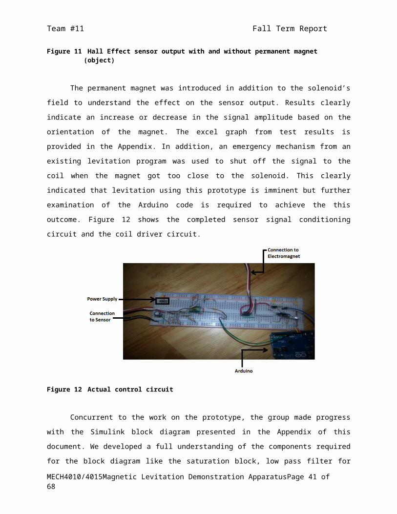
Figure 20 Winter term WBS critical path chart

16.3. Schedule
The following schedule is generated based on the WBS from the last section. Most of the
work for this term is almost completed except for the prototype and initial testing. The schedule in
Table 5 is adjusted to complete the tasks by the end of the break so that we are back on schedule for
the winter term. The next major objective for the group is to complete the prototype and order the
materials by 17th December, 2013. This is the last possible date for the group to work together after
which some of us planning to go home for holidays.
Table 6 Summary of project tasks for fall 2013 term
Task Name Duration
Start Finish Responsibility% Work Completed
Preliminary Research 6 days 9/25/13 10/2/13 Individual Effort 100%Group organization & house keeping
3 days 9/26/13 9/29/13 Group Effort 100%
Focus Groups for Subsystems
7 days 9/30/13 10/8/13
Electromagnetic Theory & Calculations - Fuyuan & Xiadong, Microcontroller & Circuitry - Marlon, Design & Sensors - Ajay
100%
Scope/Requirements 4 days10/15/13
10/18/13
Marlon & Ajay 100%
Analysis Review Pannel Inputs
1 day10/20/13
10/20/13
Group 100%
Summary of Findings of Focus Groups
2 days10/20/13
10/21/13
Individual 100%
Concept Generation and Selection
3 days10/24/13
10/27/13
Group 100%
Theory Evaluation and Calculations
3 days10/31/13
11/4/13 Fuyuan & Xiadong 100%
Conceptual Design Report
3 days 11/5/13 11/7/13 Marlon & Ajay 100%
Solid Works Model 1 day11/20/13
11/20/13
Fuyuan & Xiadong 100%
List of Materials required for Prototype
1 day11/20/13
11/20/13
Group 100%
Material Collection 5 days 11/4/13 11/8/13 Ajay 100%
Embodiment Report 3 days11/20/13
11/22/13
Group Effort 100%
Prototype Building 14 days11/10/13
11/27/13
Marlon & Ajay 85%
Prototype Testing 4 days11/24/13
11/27/13
Marlon 45%
Interim Presentation 5 days11/24/13
11/28/13
Group Effort 100%
Fall Design Report 5 days 11/27/1 12/3/13 Group Effort 100%

Team #11 Fall Term Report
3
Purchase Parts 1 day12/10/13
12/11/13
Group 85%
The group personally invested money to purchase the parts needed for the prototype with
the exception of the control circuit components and the power supply. Invoices from purchases will
be submitted to the Mechanical Department office with consent from the project supervisor to
claim the sum.
Next table in the section indicates the required number hours from individual team
members and as group to finish the remaining tasks left in this term. We are planning to work in the
break so we are well prepared for the 2014 winter term.
Table 7 Breakdown of remaining hours of work for the winter break
Team Member Name Major Responsibility Hours of Work RequiredMarlon McCombie Complete Prototype for
Levitation12
Ajay Puppala MathWorks Simulink 10Fuyuan Lin Solid Works Modeling 6Xiadong Wang MathWorks Simulink 8Group Ordering Required Materials 5Total Hours of Work Required 41
Winter term, 2014 schedule is laid out based on WBS from Figures 17 and 18. The following
table estimates the time it takes to complete the tasks due in the term. It also indicates the
percentage of work completed for each task. A value higher than zero (please note the values are
only an approximation) suggests that work from fall term can be used directly towards completion
of the tasks in the winter term.
Table 8 Summary of project tasks for winter 2013 term
Task Name Duration Finish Responsibility % Work Completed
Gather Parts 2 days 1st week January Marlon & Ajay 15%Review Fall Report 1 day 1st week January Group task 0%Building PhasePrototype Testing 3 days 1st -2nd week January Marlon & Xiadong 30%Complete Simulink Block Diagram
7 days 2nd -3rd week January Fuyuan & Ajay 25%
Implement Control Theories 4 days 3rd week January Group 0%Build GUI using Simulink 4 days 4th week January Fuyuan & Ajay 0%Rebuild circuitry 1 day 4th week January Marlon 85%Build Stand & Electromagnet 3 days 4th week January Xiadong 5%System Integration 5 days 2nd week February Group task 35%Testing Phase
MECH4010/4015 Magnetic Levitation Demonstration Apparatus Page 43 of 51

Team #11 Fall Term Report
Set up System in Lab 3 days 2nd week February Group task 0%Testing system 15 days 3rd– 4th wk. February Group task 0%Collect and Sample data 10 days 1st -3rd week March Scheduling 0%Test completion 2 days 4th week March Marlon & Ajay 0%DeliverablesBuild Report 4 days 2nd week February Group task 20%Update Website 2 days 1st week April Ajay 15%Final Report 4 days 1st week April Group task 15%Final Presentations 2 days 1st week April Group task 10%
16.4. Specialized Facilities and Resources
16.4.1. Facilities
The following is a list of facilities that are required for the project duration and a short
description for their necessity:
Design workbench
o For testing prototype apparatus and for storing materials and components
to allow easy access by team members
Measurements Laboratory (C255)
o For testing EM with varying current input using an bench power supply;
especially in the unlikely case that the currents needed for levitation are
potentially dangerous
Machine Shop/Carpentry Shop
o For fabricating a suitable chassis for the final apparatus
16.4.2. Additional Advisors
Name: Dr. Ya-Jun PanPosition: Professor, Mechanical Dept.Email: [email protected]
Name: Dr. Timothy LittlePosition: Professor, Electrical Dept. Email: [email protected]
Name: Jonathan MacDonaldPosition: Electrical Technician, Mechanical Dept.Email: [email protected]
Name: Angus MacPhersonPosition: Mechanical Technician, Mechanical Dept. Email: [email protected]
MECH4010/4015 Magnetic Levitation Demonstration Apparatus Page 44 of 51

Team #11 Fall Term Report
Name: Corey MacNeilPosition: Automation Specialist, Jentronics Ltd.Email: [email protected]
MECH4010/4015 Magnetic Levitation Demonstration Apparatus Page 45 of 51

Team #11 Fall Term Report
17. References
Brandt, E. H. "Levitation in Physics." N.p., 20 Jan. 1989. Web. 28 Oct. 2013.]
"Electronic Components Distributor | DigiKey Corp. | CA Home Page. N.p., n.d. Sat. 03 Nov. 2013
“LEGO Mindstorms Online Store.” http://shop.lego.com/en-CA/LEGO-MINDSTORMS-NXT-2-0-
8547. Retrieved November 6, 2013
“Liquidware Online Store” http://www.liquidware.com/shop/show/ARD-UNO/. Retrieved
November 6, 2013
"RobotShop : The World's Leading Robot Store." RobotShop. N.p., n.d. Sat. 03 Nov. 2013
Thompson, Marc T. "Eddy Current Magnetic Levitation: Models and Experiments." IEEE. N.p., 200.
Web. 28 Oct. 2013.
Williams, Lance. "Electromagnetic Levitation Thesis." N.p., 2005. Web. 28 Oct. 2013.
Shuaibu, D. S. S. & Adamu, S. S., “Design, Development and Testing of an Electromagnet for magnetic
levitation system”, Nigeria, Publication date unknown
“MathWorks MATLAB/Simulink website.” http://www.mathworks.com/products/simulink/. Retrieved
November 20, 2013
Lieberman, J. 2005, “Magnetic levitation project.” http://bea.st/sight/levitation/. Retrieved
November 20, 2013
Mikonikuv Blog, “Arduino Magnet Levitation – detailed description.”
http://mekonik.wordpress.com/2009/03/17/arduino-magnet-levitation/. Retrieved
November 20, 2013
Arduino UNO webpage. http://arduino.cc/en/Main/arduinoBoardUno. Retrieved November 20,
2013
ATmega238 datasheet. http://www.atmel.com/Images/doc8161.pdf. Retrieved November 20,
2013
Honeywell SS49 datasheet. http://www.wellsve.com/sft503/Counterpoint3_1.pdf. Retrieved
November 20, 2013
MECH4010/4015 Magnetic Levitation Demonstration Apparatus Page 46 of 51

Team #11 Fall Term Report
Appendix A Simulink block diagram for electromagnetic levitation
Figure 21 Simulink block diagram for electromagnetic levitation
MECH4010/4015 Magnetic Levitation Demonstration Apparatus Page i of li

Team #11 Fall Term Report
Appendix C Sample Programs This example code was modified from examples supplied by the Arduino IDE.int led = 3;#define sensorPin 0int monitoring = false;
// the setup routine runs once when you press reset:void setup() // initialize the digital pin as an output. pinMode(led, OUTPUT);
Serial.begin(9600); Serial.println("Ready"); Serial.println("m - toggle monitoring");
// the loop routine runs over and over again forever:void loop() // fade in from min to max in increments of 5 points: for(int fadeValue = 0 ; fadeValue <= 255; fadeValue +=5) // sets the value (range from 0 to 255): analogWrite(led, fadeValue); // wait for 15 milliseconds to see the dimming effect delay(15);
int sensor=analogRead(sensorPin); checkSerial();
if (monitoring) Serial.println(sensor);
// fade out from max to min in increments of 5 points: for(int fadeValue = 255 ; fadeValue >= 0; fadeValue -=5) // sets the value (range from 0 to 255): analogWrite(led, fadeValue); // wait for 15 milliseconds to see the dimming effect delay(15);
int sensor=analogRead(sensorPin); checkSerial();
if (monitoring) Serial.println(sensor);
void checkSerial() if (Serial.available())
MECH4010/4015 Magnetic Levitation Demonstration Apparatus Page iii of li

Team #11 Fall Term Report
char ch = Serial.read(); if (ch == 'm') monitoring = ! monitoring;
MECH4010/4015 Magnetic Levitation Demonstration Apparatus Page iv of li

Team #11 Fall Term Report
Appendix B Design Calculations for Electromagnet
Table 9 Design calculations for electromagnet
Options 1.000 2.000 3.000 4.000 LimitationCore Diameter (former) (mm)
30.000 30.000 30.000 30.000 30.000
Density of object (kg/m^3) 7850.000 7850.000 7850.000 7850.000 7850.000Diameter of object (mm) 25.000 25.000 25.000 25.000 25.000Volume of ball (m^3) 0.000 0.000 0.000 0.000 0.000Mass of ball (kg) 0.064 0.064 0.064 0.064 0.064Gravity 9.810 9.810 9.810 9.810 10.810Pole area 0.001 0.001 0.001 0.001 0.001B (wb/m^2) 0.059 0.059 0.059 0.059 0.059Air gap (mm) 100.000 90.000 80.000 0.000 300.000Turns (n) 1000.000 1000.000 1000.000 1000.000 1000.000r (half diameter of core) (mm)
15.000 15.000 15.000 15.000 15.000
Length of former (mm) 100.000 100.000 100.000 100.000 100.000Cylinder (total area) (m^2) 0.011 0.011 0.011 0.011 0.011H (AT/m) 46997.891 46997.891 46997.891 46997.891 46997.891Magneto-motive force (mmf) 4699.789 4229.810 3759.831 0.000 14099.367I (A) 4.700 4.230 3.760 0.000 14.099F (N) 15.042 15.042 15.042 15.042 15.042Wire chosen AWG 19 gage() (mm) 0.912 0.912 0.912 0.912 0.912Maximum number of wires in the first layer
109.666 109.666 109.666 109.666 109.666
Stacking factor 0.900 0.900 0.900 0.900 0.900Total # of layers 10.132 10.132 10.132 10.132 10.132Total length of wire (layers) 1039.264 1039.264 1039.264 1039.264 1039.264Total length of wire (total cylinder) (mm)
102574.682 102574.682 102574.682 102574.682 102574.682
(m) 102.575 102.575 102.575 102.575 102.575The unitl Resistor of chosen wire (Ohms per 1000 ft)
8.051 8.051 8.051 8.051 8.051
Total Resistor 2.709 2.709 2.709 2.709 2.709Total Voltage 12.734 11.460 10.187 0.000 38.201Heat produced by wire 34.501 31.051 27.601 0.000 103.502
MECH4010/4015 Magnetic Levitation Demonstration Apparatus Page v of li