Embed Size (px)
DESCRIPTION
Project Wisdom Stone Networking using MiWi. Done By: Amnon Balanov & Yosef Solomon Supervisor: Boaz Mizrachi Project ID: d02310. Project Wisdom Stone. Small sensors, with very low power consumption Planted under roads Performing monitoring of road maintenance status. - PowerPoint PPT Presentation
Citation preview

Project Wisdom StoneNetworking using MiWi
Done By: Amnon Balanov & Yosef SolomonSupervisor: Boaz MizrachiProject ID: d02310

Small sensors, with very low power consumption
Planted under roads Performing monitoring of road maintenance
status
Project Wisdom Stone
THIS INFORMATION WILL SAVE MONEY BY DECREASING MAINTENANCE COSTS AND TIME!

Based on a PIC24 micro-processor
Networking (two alternatives):o 2.4 GHz enabled by a MRF24J40 IEEE 802.15.4 Tx/Rx.o 433 MHz enabled by a MRF49XA Tx/Rx.
Networking will run MiWi (Microchip propriatory S/W stack)
***All components are made by Microchip.
Project Wisdom Stone

The design and implementation of a networking S/W stack who’s functions will be:
1. Transmissions of aquired data to a PC via similar unit
2. Parsing commands received from PC station
3. WAKE interrupts from sleep - for sensing sessions
Project Goals

Tx/Rx◦ Communications with the PC unit
microSD memory chip◦ Stores aquired data
PIC interrupts◦ Wake/Transmission interrupts
System I/O

Extra BoardPICtailEvaluation Board – Explorer
16
MicroCTRL - PIC24FJ256GB11
0
General HW Scheme
Sensor Array
NetworkingMRFJ40MB
ORMRF49XA
MEM- Flash & SRAM
MEM- microSD
SPISPI
SPI

Internal flash Program Memory- 256kB◦ Current tests show 10% usage
SRAM Data Memory- 16kB◦ Current tests show 10% usage◦ We will have a double buffer, a block length each,
for communications (block=1kB; currently) 3 SPI Ports
◦ We will use one for the MRF & one for the µSD.
PIC-24FJ256GB110

MRFJ40MBUses 2.4GHz RFUses O-QPSK modulation.Receiver FIFO- 144 byte, interrupts when a
whole packet was received.Transmitter FIFO- 128 byte.Packet header length ~20 Bytes (TBD)Power: 19-23 mA Working
~2 µA Sleeping
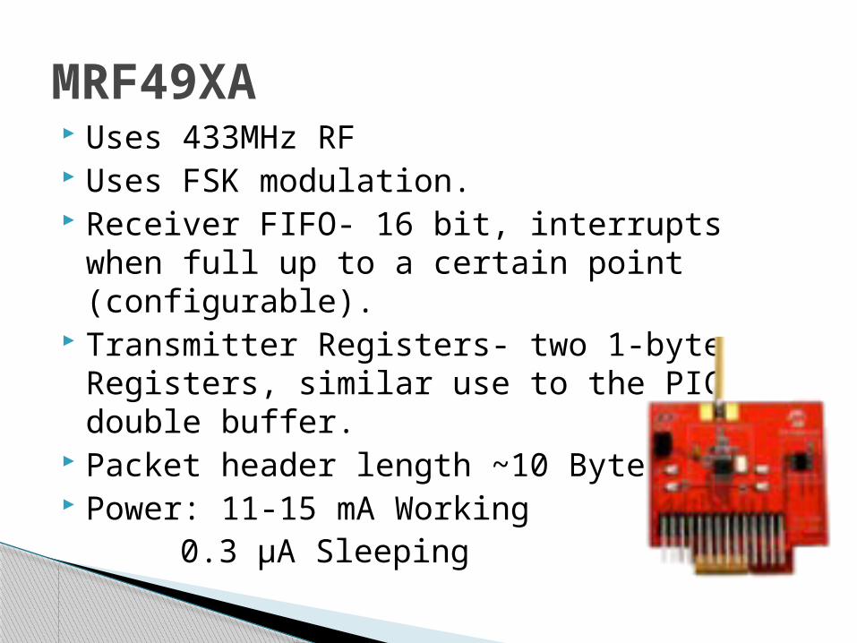
Uses 433MHz RF Uses FSK modulation. Receiver FIFO- 16 bit, interrupts when full
up to a certain point (configurable). Transmitter Registers- two 1-byte Registers,
similar use to the PIC double buffer. Packet header length ~10 Bytes (TBD) Power: 11-15 mA Working
0.3 µA Sleeping
MRF49XA

MRF24J40◦ 250 kbps transmission speed
MRF49XA◦ 115.2 kbps digital transmission speed◦ 256 kbps analog transmission speed
PIC24FJ256GB110◦ computational power of 16 MIPS◦ sampling rate of 500 ksps
microSD◦ reads and writes are in the MB/s range
System Speeds

General Software Layers Diagram

Definition and support the following working modes:◦ Store samples (SS): Samples are stored in non-volatile
memory for long period. ◦ Transmit samples (TS): Samples are read and
transmitted from non-volatile memory through Wireless/UART/USB.
◦ Online sample and transmit (OST): Samples are read from sensor and then transmitted through UART/USB/Wireless, using internal SRAM memory (double buffer mechanism), without access to non-volatile memory.
Sample / Transmit working modes

The device is activated using a well defined CLI (Command Line Interface).
The command line strings are received from either:◦ TXRX wireless port◦ USB port◦ UART port◦ Internal ROM table (Configuration table)
Each command will be executed, and a prompt prefix, followed by the command result, will be returned to the command origin source (TXRX, USB or UART).
CLI Commands

We will write a parser converting the different commands to a short field divided command.
Work on the parser is in its early stages. For example:
◦ eeprom <sub command> <optional parameters>◦ |5 bit command code| |3 bit sub-command| |8-bit optional|
CLI Commands Parsing
As was decided, we use the MiWi SW Stack.◦ MiWi is a proprietary stack designed by
Microchip, free to use. The stack is implemented as general as
possible and suits to the proposed HW networking modules.
We use the MiWi P2P protocol.
MiWi SW Stack

The MiWi Protocol is divided into two parts:◦MiApp - upper level used to connect our
application with the MiWi P2P protocol
◦MiMAC - Using the MiMAC layer, we can easily switch between different RF transceivers such as MRF24J40 and MRF49XA.
MiWi Protocol (Cont.)

MiWi Protocol Layers

This layer will give 5 major interfaces:◦ Initialization- allows configuration of selected
hardware.◦ Hand-shaking-allows discovering and
connecting to peers and network.◦ Receiving- allows receiving information over the
air.◦ Transmitting- allows sending information over
the air.◦ Extended Functionality- allows environment
noise and power saving control.
MiApp Layer
The MiMAC Layer allows us the abstraction of the Transceiver driver- we use it regardless of the driver used (at least in theory)
Mainly implements the MiApp API
MiMAC Layer

Configuration File
Allows the easy configuration of the whole
application:
Switching between Transceivers
Enabling/Disabling different functions of the SW
stack
Further Development- Allows choosing the Protocol
TXInit()◦ Initialize network parameters.◦ The sensor creates a network.
TXBatchInit()◦ Initialize a new batch.
TXBlock()◦ Transmits block of size 1KB.
TXStop()◦ Ends transmission.
TXRXDeviceTasks()◦ This function will take care of the transceiver periodic
tasks (handle TX and RX tasks).
TXRX Commands- Main Loop API

Network Diagram
INIT INIT
Send Command
Interpret command & Send Data
Go To Sleep
Receive Data
New/End Session
The sensor side PC side

In order to comply with time constraints of other parts of the WiStone we will test to see how big a payload we can use.
In case we see a packet’s transmission cannot be interrupted and in order to allow easy coordination, we will make the transmission of a packet atomic (non-preemptive).
Coordination in the WiStone

The two Transceivers support a sleep mode. They save the current status on
configuration registers to allow easy wake up.
The only way to wake up the transcievers is through pre-programmed timers on the transceivers or the PIC.
We need to figure out how to allow access not at a pre-determined time.
Sleep
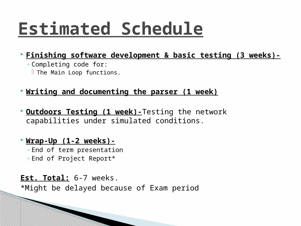
Finishing software development & basic testing (3 weeks)- ◦ Completing code for:
The Main Loop functions.
Writing and documenting the parser (1 week)
Outdoors Testing (1 week)-Testing the network capabilities under simulated conditions.
Wrap-Up (1-2 weeks)-◦ End of term presentation◦ End of Project Report*
Est. Total: 6-7 weeks.*Might be delayed because of Exam period
Estimated Schedule