Embed Size (px)
Citation preview

1. PROJECT TITLE
The design and construction of ”LED DOT MATRIX DISPLAY BOARD”.
1.1 BRIEF An Led Dot Matrix Display Board is a programmable board used mainly for the purpose of advert. This technology makes use of individual leds to form an LED matrix screen of either 5X7, 5X8 or 8X8 matrix screen. This led matrix is multiplexed (i.e. expanded by making use of some special digital decoder ICs (integrated circuit chips). These digital decoder chips are linked to an on-chip microcomputer chip called microcontroller. This microcontroller controls the output of these digital ICs with respect to the written code (i.e. the program running the controller) in order for the written advert to be displayed on the LEDs matrix screen.
NAME AND PROGRAMME OF STUDYName: Student ID: Program of Study:
2. AIMS OF THE PROJECT 3.
The use of digital bill board such as “LED DOT MATRIX DISPLAY BOARD” for advert. To design and analyse a programmable “LED DOT MATRIX DISPLAY BOARD” Build and develop a programmable “LED DOT MATRIX DISPLAY BOARD” for advert purpose. Produce a technical report containing the evaluations of the design and build of a programmable “LED DOT MATRIX
DISPLAY BOARD” of 6000 words. To present a completed construction of an “LED DOT MATRIX DISPLAY BOARD”.
4. PROJECT DEFINITION
4.0 Overview

The main purpose of this design is to solve the problem of limited advert write ups space encountered when using the conventional known metallic bill board/sign post for listing of advert items. The use of a digital “LED DOT MATRIX DISPLAY BOARD” for advert purposes can solve this problem since this digital bill board displays it advert content in a moving format thereby making it possible for lots of advert content to be written to the on-chip microcomputer chip.
Uses — led dot matrix digital display advert board is commonly used in the banking systems to display bank’s services, currency exchange rate etc, it is used in the eateries to display food menu items, and also in the airport to display the flight time etc.
Advantages — this technology has a greater advantages over the old fashioned means of bill board advert system where paint is been used in writing the advert content on the sign post board which will gradually fade away with time. Whereas in the case of the led dot matrix display board, advert content are been typed and stored in the on-chip microcomputer memory. Content of the led dot matrix display board can also be erased easily and reprogrammed compared to the ordinary paint bill board.
Reliability —the design is highly reliable since there is nothing like erasing of the paint used in the advert write ups as in the case of the ordinary bill board.
4.1 COMMERCIAL APPEAL This design have a high commercial appeal in the sense that many business firms, banks, eateries, hotels airport etc, makes use of digital display for their advert purposes because it makes it easier and possible for them to outline all their products, goods and services in order to enhance their business activities and profit making by the means of using digital display board.
4.2 DESIGN & BUILD To design an led dot matrix display board, an intense knowledge of the individual components parts used for the design is highly needed, the knowledge of how program code flows within the microcontroller chip is needed as well as the hardware configuration of the whole system. Before carrying out the hardware construction, I took time using simulator software such as Multisim and proteus electronics design suit to carry out the design and test run it in the simulators to see the performance of the design and from the output of the simulated circuit, I made all necessary changes in order to see that the design is working as expected.

5. RESOURCES
Simulation software – proteus Assembler IDE software Library Provided Books Internet Journals Laboratory Lab Equipment – Digital Multi-meter, oscilloscope, soldering iron, drilling machine, screw drivers etc. Electronic components– The electronics components used for this design are as follows:
-wires-connectors-LED (Light Emitting Diodes)-10kΩ resistors-1kΩ resistors-10µF capacitors-1000uF capacitors-Transistors NPN-74LS138 Decoder IC-ATMEL Microcontroller chip-12MHZ crystal oscillator-30pF ceramic capacitor-40 pins IC socket-16 pins IC sockets-Aluminum Frame- 12”X48” Glass screen-7805 voltage regulator-Bridge rectifier diode-10cm X 24cm Vero Board-220V-to-6V step down transformer-Screws

This is what is displaying on the screen. WELCOME TO MARKEATON CAMPUS, FACULTY OF ARTS, DESIGN AND TECHNOLOGY, UNIVERSITY OF PORT…..
Hi, u need to make the project clear, the reason behind the project, why LED display for the project, think about the current price of the device available in the market, research the facilities available with the commercially available (equal) device, and finally, think more about the user interface. hope u understand, just points u need to focus more on the report... Thanks
BRIEF DESCRIPTION OF THE DOTMATRIX DISPLAY BOARD AND ALL ITS COMPONENTS PARTSLISTS OF ALL THE COMPONENTS PARTS:
(1) LED(2) 1KΩ RESISTOR(3) 10KΩ RESISTOR(4) 10UF CAPACITOR(5) 30PF CAPACITOR(6) 12MHZ CRYSTAL OSCILLATOR(7) 7805 VOLTAGE REGULATOR(8) TRANSFORMER(9) IN4001 RECTIFIER DIODE(10) 22UF CAPACITOR(11) 16 PINS IC SOCKET(12) 74138 DECODER IC(13) 40 PINS IC SOCKET(14) ATMEL AT89C55 CONTROLLER(15) STRIP VERO BOARD(16) WIRES(17) PLY BOARD (CEILING BOARD)(18) ALUMINUIM PROFILE

(19) TINTED GLASS
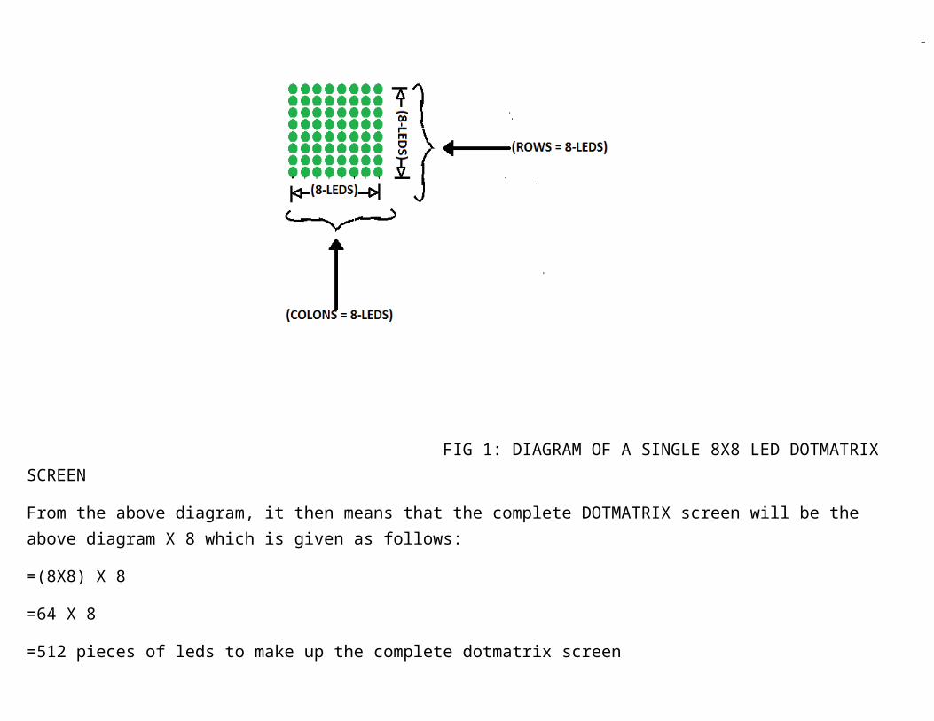
1. LED : The leds used in this project design is a type called supper bright or outdoor led. It is the major component used in forming the 8X8 led matrix screen.
The 8X8 led matrix screen is made up of 8-Rows of leds and 8-colons of leds and in this dotmatrix display board, we are using eight pieces of this screen. See schematics circuit diagram and also block diagram of a single arrangement of 8X8 led dotmatrix screen below in order to understand what I mean.

FIG 1: DIAGRAM OF A SINGLE 8X8 LED DOTMATRIX SCREENFrom the above diagram, it then means that the complete DOTMATRIX screen will be the above diagram X 8 which is given as follows:=(8X8) X 8=64 X 8=512 pieces of leds to make up the complete dotmatrix screen
2. 1KΩ RESISTOR: The 1KΩ resistor used in this project design are 8-pieces in number, and its function in the circuit is to full-up the anode voltage of the 8X8 led matrix screen with respect to +2ve output from the ATMEL AT789C52 microcontroller pins 1-to-8. See diagrams below to understand what I mean.
FIG 2: PULL UP RESISTORS
3. 10KΩ RESISTOR: The 10kΩ resistor used in this project design is 1-pieces in number, and it is connected in series with a 10uF capacitor to serve as automatic-reset of pin 9 of the Atmel AT89C52 microcontroller IC, which is necessary for proper functioning of the microcontroller IC. See diagrams below.

FIG 3A: DIAGRAM OF 10KΩ RESISTOR
FIG 3B: DIAGRAM OF AUTOMATIC RESET CONFIGURATION4. 10UF CAPACITOR : The 10uF capacitor as explained above is connected together with the 10K
resistor, for the purpose of automatic resetting of the microcontroller for its proper operation. See diagram below.

FIG 4: DIAGRAM OF 10UF ELECTROLYTIC CAPACITOR
5. 30pF CAPACITOR: The 30pF capacitor used in this project design are 2-pieces in number, they are connected together in series and center tapped to ground (i.e. GND). They are also connected in parallel with a 12NHZ crystal oscillator via pins 18 and 19 of the microcontroller IC. See diagram below.
FIG 5: DIAGRAM OF 30PF CERAMIC CAPACITOR

6. 12MHZ CRYSTAL OSCILLATOR : The 12MHZ crystal oscillator used in this project design as explained above is responsible for proper frequency operation of the Atmel AT89C52. See diagram below.
FIG 6: DIAGRAM OF FREQUENCY RESONATOR
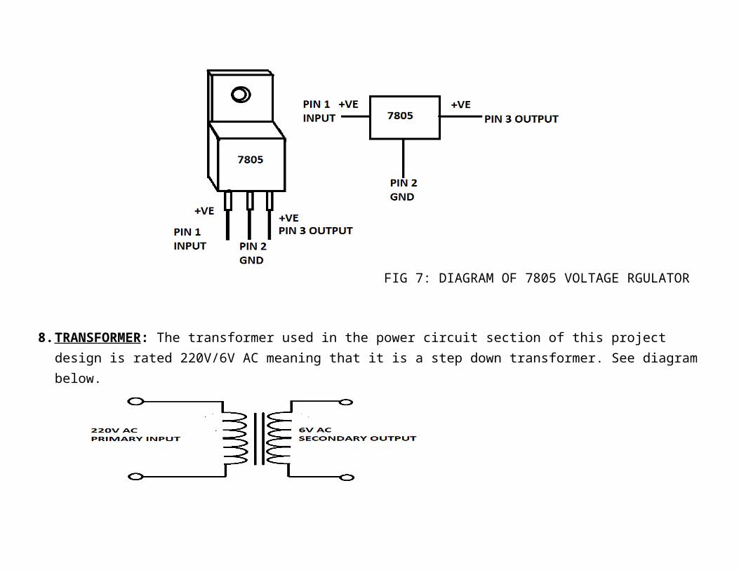
7. 7805 VOLTAGE REGULATOR : The 7805 voltage regulator used in the power circuit section of this project design helps to regulate +6V DC output from the rectified section to +5V DC since that is the maximum voltage required all many digital IC such as the ATMEL AT89C52 microcontroller IC and the 74138 decoder IC. See diagram below.

FIG 7: DIAGRAM OF 7805 VOLTAGE RGULATOR
8. TRANSFORMER : The transformer used in the power circuit section of this project design is rated 220V/6V AC meaning that it is a step down transformer. See diagram below.
FIG 8: DIAGRAM OF A SIMPLE 220/6V AC STEP-DOWN TRANSFORMER

9. IN4001 RECTIFIER DIODE: The IN4001 rectifier diode used in the power circuit section of this project design are 4-pieces in number and as the name implies, it is used to rectify the 6V AC coming out from the secondary output of the transformer to 6V DC. See diagram below.
FIG 9: DIAGRAM OF IN4001 RECTIFIER DIODE
10. 22UF CAPACITOR: The 22uF electrolytic capacitor used in the power circuit section of this project design is 1-piece in number and its function is to smoothen (i.e. to filter any AC ripples which may be present after rectification. See diagram below.
FIG 10: DIAGRAM OF 22UF ELECTROLYTIC CAPACITOR
11. 16 PINS IC SOCKET: The 16 pins IC socket used in this project design are 9-pieces in number and it is the base where the 74138 decoder ICs are to be seated on. See diagram below.
FIG 11: DIAGRAM OF 16-PIN IC SOCKET
12. 74138 DECODER IC: The 74138 decoder IC used in this project design are 9-pieces in number. The decoder has 8 active low outputs labeled as follows; pin 15=Q0, pin 14=Q1, pin 13=Q2, pin 12=Q3, pin 11=Q4, pin 10=Q5, pin 9=Q6, pin 7=Q7. The major function of this decoder is to decode the binary output signals from the microcontroller to readable text. In this project design, 8-pieces of the 74138 decoders out of the 9—pieces are called the slaves while the remaining 1-piece is called the master and each of the slave decoders gets active low signals from the master with respect to the 8-bit binary signals they get through pins 1, 2, and 3 (i.e. A, B, and C ) from the microcontroller’s output pins 10, 11, and 12 while the master gets active low signal directly from the ground (i.e. GND) with respect to the 8-bits signals gotten from the microcontroller’s output pins 13, 14, and 15. Each of the slave decoders are responsible for driving one screen of 8X8 matrix screen. See diagrams below.

FIG 12A: DIAGRAM OF 74138 DECODER IC

FIG 12B: DIAGRAM SHOWING ONE SLAVE DECODER DRIVING A SINGLE BLOCK OF 8X8 MATRIX SCREEN
13. 40-PINS IC SOCKET: The 40-pins IC socket used in this project design is 1-piece in number and it is the base where the ATMEL microcontroller IC is to be seated on. See diagram below.
FIG 13: DIAGRAM OF 40-PINS IC SOCKET14. ATMEL AT89C52 MICROCONTROLLER CHIP : The Atmel 89C52 microcontroller IC is the
major components of this dotmatrix project design. This device is a microcomputer in a chip form. This is because it has all it takes to be called a complete computer in a chip package. That is it has I/O ports, ROM, RAM, and storage locations where the written advert program is been stored. This device have four I/O ports called PORT 0, PORT 1, PORT 2 and PORT 3 (i.e. P0, P1, P2, AND P3). In the case of this project design, I am making use of PORT 1 and PORT 3 (i.e. pins number 1 through 8 makes up the PORT 1, and pins number 10 through 17 makes up the PORT 3) then the remaining PORTS (i.e. PORT 0 and PORT 2 are not use), pins number 21 through 28 makes up the PORT 2 and pins number 32 through 39 makes up the POTR 0, pin 9 is the reset , pin 18 and 19 are the frequency resonator pins (i.e. where the 12MHZ crystal oscillator and the 30PF capacitors are been

attached as shown below), pin 20 is the GND, pin 40 is the VCC, pin 31 is connected to VCC when using the internal ROM memory of the chip or else it is connected to GND together with pins 30 and 29 when using external ROM memory device . See diagram of the complete design and also the power circuit for this design below.
FIG 14: DIAGRAM OF ATMEL AT 89C52 MICROCONTROLLER IC

FIG 17: COMPLETE SCHEMATIC CIRCUIT DIAGRAM OF 8X8 LED DOTMATRIX DISPLAY BOARD
FIG 18: SCHEMATIC CIRCUIT DIAGRAM OF 5VOLTS REGULATED DC POWER SUPPLY

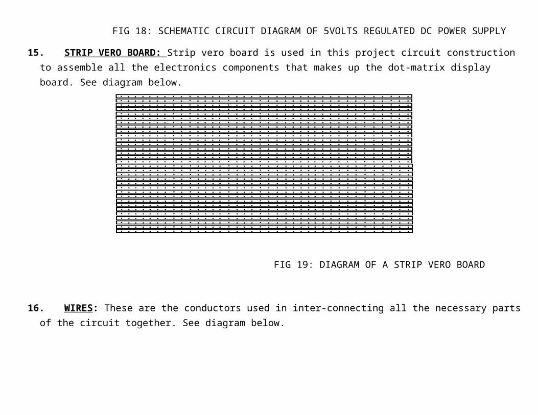
15. STRIP VERO BOARD: Strip vero board is used in this project circuit construction to assemble all the electronics components that makes up the dot-matrix display board. See diagram below.
FIG 19: DIAGRAM OF A STRIP VERO BOARD
16. WIRES : These are the conductors used in inter-connecting all the necessary parts of the circuit together. See diagram below.
FIG 20: DIAGRAM OF MULTI-COLOUR WIRES

17. THE PLY BOARD (WOODEN CEILING BOARD): The leds used in forming the dotmatrix screen are all assembled on this ply board, and this board is sprayed with a black paint to give it a finished fine look. See illustrative diagram below.
FIG 21: DIAGRAM OF A SPRAYED PLY BOARD (WOODEN CEILING BOARD)
18. ALUMINUM PROFILE : This is the aluminum frame material used in casing of the completed dotmatrix design.
19. TINTED GLASS : Tinted glass is used to cover the screen of the dotmatrix finished design to shade it as well as to give it an attractive look. See diagram of the complete Aluminum and Tinted glass framing below.

BLOCK DIAGRAM OF 8X8 LED DOTMATRIX DISPLAY SYSTEM
The above diagram shows the block diagram of 8X8 led dot-matrix display system. The Atmel AT89C52 microcontroller IC is the major component used in this dot-matrix display system. It controls all other parts of the circuit components as the name implies. For the Atmel AT89C52 microcontroller IC to function properly, the automatic reset circuit configuration must be done using a 10KΩ resistor and a10uF capacitor, and also the frequency oscillation circuit configuration should be properly connected or else the microcontroller will not function at all. After these configurations (i.e. Auto reset and frequency oscillation ) settings, the microcontroller is ready for any task required of it. Since the microcontroller is a complete computer in a single chip package, the 74138 decoders both the master and the slaves are connected to its I/O ports (i.e. input / output ports) to enable them to get 8-bits signal from the microcontroller. This signal is nothing but the written program code which is finally converted to zeros

and ones (i.e. 0s and 1s) signals which is understandable by the machine (i.e. the ATMEL AT89C52 microcontroller chip). The master decoder gets 8-bits binary signal from the microcontroller and uses this signal to control the slaves decoders by taking decision on which of the slave decoders to turn ON. The microcontroller also controls all the slave decoders by determining which one to turn ON at a particular point in time and also the slave decoders in turns controls each of the 8X8 led matrix screen based on the signal they get from the microcontroller. The anode of the 8X8 led matrix screen gets positive voltage source from the pins 1-8 of the microcontroller with respect to the 8-pull up 1KΩ resistors. While the cathode is connected to the output of the 74138 slave decoders in order to get negative voltage source to complete the circuit.PROTEUS CIRCUIT DIAGRAM


![LAND SELECTION[1] - secure.expertsmind.comsecure.expertsmind.com/attn_files/982_Advanced... · Web viewThe city of Denver and Greiner/MKE would function as the project management](https://img.pdfslide.net/doc/110x75/5a733c9e7f8b9a98538e6115/land-selection1-doc-file-web-viewthe-city-of-denver-and-greinermke.jpg)