Embed Size (px)
Citation preview
1
Projeto de uma cadeira de rodas para andar na Praia
Luís Brazão
Instituto Superior Técnico, Universidade de Lisboa – Portugal
July 2019
This dissertation presents a study on the structural and functional constitution of a beach
wheelchair for persons with reduced mobility and with body mass up to 60 kilos, analyzing several
concepts and potential improvements. The present research is motivated by the search for
wheelchair improvements such as those provided by the More Moving Moments project, the first
project of the non-profit association, More Moving Moments -MMM-, which provides beach chairs
for children. One of the objectives is to respond to obstacles that arise in the daily life of people
with psychomotor difficulties and their families. The first part, analyzes the type of system that
characterizes the wheelchair and what parameters can be modified in order to innovate the
inaccessibility in sandy terrains. It is presented the difficulty of traveling, the structural problems
of a beach wheelchair and the performance criteria, as well as the concepts, materials, priority
aspects and solutions available in the market (especially in Portugal). The second part proposes
an improved design of a wheelchair for the beach, taking into account the specifications indicated.
Key words: beach wheelchair; mechanisms; mobility on the beach; wheelchair structural
analysis; mechanical design project; reduced mobility; PVC pipes
1. Introduction
1.1. Framing and definition of the theme
Reduced mobility consists in the "situation of
the individual whose movements are limited"
[1]. One way to overcome these difficulties is
to create products, services or projects that
include all human diversity, not excluding
individuals who are at a disadvantage.
Throughout the ages several persons like
Johan Haustach, Stephan Farfler, Herbert A.
Everest or H.C Jennings, have been
developing the idea of the wheelchair. Social
discrimination and inaccessibility to various
localities led to the creation of mechanisms
and incorporation of others, giving rise to the
first propulsion wheelchair [2]. Throughout
its history, the wheelchair has been adapted,
with the invention of the folding wheelchair,
with the weight reduction due to changing
the type of materials, making it lighter and
also through the introduction of electric
propulsion.
A more socially active life for people with
reduced mobility and awareness of society
has led to an evolution of the object in
2
question. Currently at national level there are
220 beaches that allow the use of a
wheelchair prepared mechanically and
structurally for the environment. In this case,
it is MMM's objective to reduce the
limitations of children with reduced mobility
by adapting the product to the environment,
in order to provide them with the possibility
of improving mobility on the beach.
Wheelchairs are available free of charge at
beaches such as Grândola, Mafra and
Sesimbra, in favor of this MMM project,
which provides easy access to them. These
chairs feature a durable and non-corrosive
PVC structure, are equipped with WheelEEZ
wheels [3] and are designed for carrying
children up to 27 kilos [4], with the help of
another person.
1.2. Problem statment
The primary importance of this challenge is
improve mechanically and structurally the
wheelchair model available from the MMM
association in order to provide an improved
wheelchair meeting the following guidelines:
Minimize chair weight;
Low cost;
Ease of assembly;
Capacity up to 60 kilos, i.e. a 200%
increase in the capacity of the base
chair
1.3. Document structure
This document is divided into two parts. In
the first part, questions are raised on the
mechanism and structure of a wheelchair to
improve accessibility on sandy terrain, while
in the second part calculations are presented
in order to ensure the conditions necessary
to support the weight up to 60 kg, respecting
the anatomical standards of a human being.
2. Aspects that were at the origin of the
wheelchair
The construction of the prototype has as
fundamental aspect the accessibility, taking
into account the anthropometric and
ergonomic dimensions, as well as the
comfort and safety of the user.
In the Portuguese view there is a wide range
of models of wheelchairs, available in the
market. Their diversity is focused on three
fundamental aspects:
Purpose of the wheelchair model;
Physical and cognitive conditions of
the user;
Structure materials.
Regarding the design of the chair, human
ergonomic and anthropometric standards
have been taken into account, so that the
adjustment between the chair and the user
is as adequate as possible.
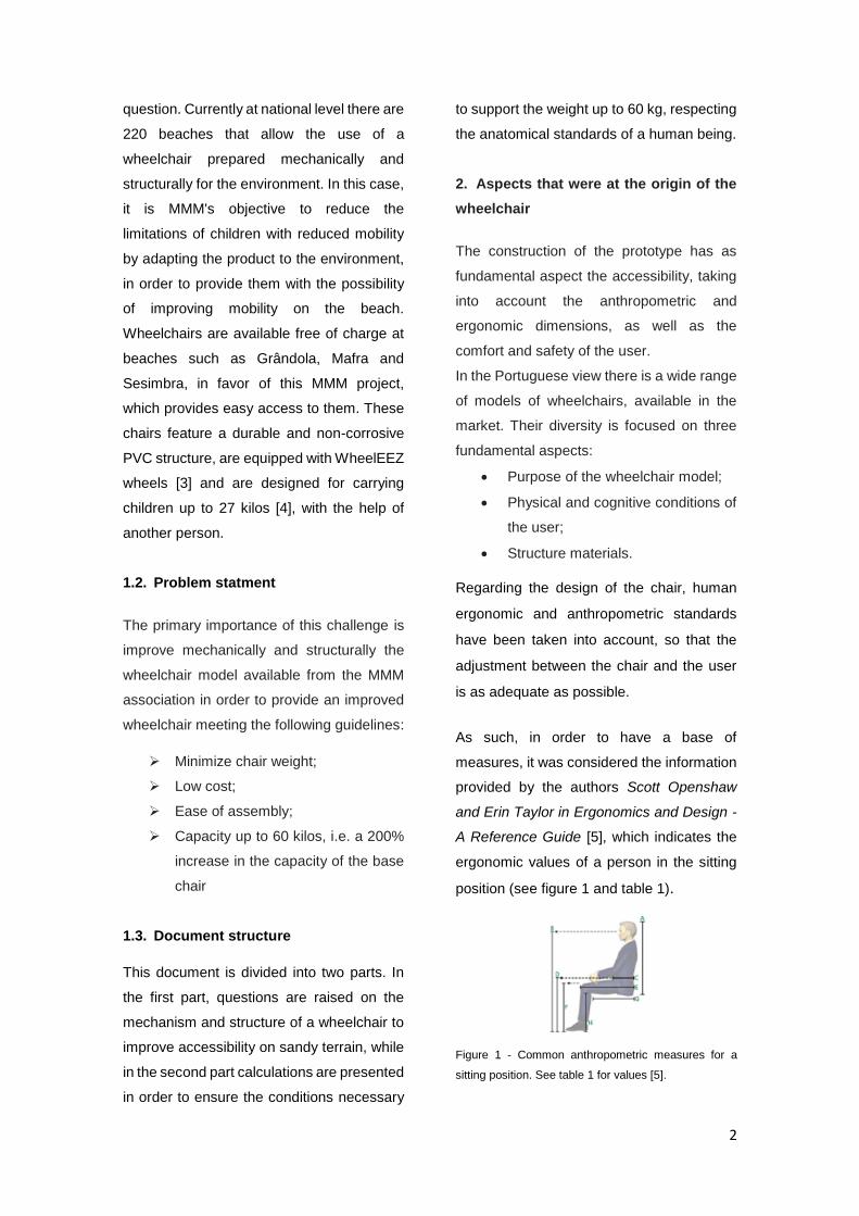
As such, in order to have a base of
measures, it was considered the information
provided by the authors Scott Openshaw
and Erin Taylor in Ergonomics and Design -
A Reference Guide [5], which indicates the
ergonomic values of a person in the sitting
position (see figure 1 and table 1).
Figure 1 - Common anthropometric measures for a
sitting position. See table 1 for values [5].
3
Table 1 - Values for the 5th to 95th percentile of the
male and female in the sitting position used in the
seating design. See figure 1 (Measured in mm) [5].
Anthropometry is also an important factor in
the design of a wheelchair, for example it
allows estimating the center of mass for
different positions of the human being.
Table 2 shows the equation (and the value
of its parameters) for the calculation of the
center of mass for two positions: standing
and sitting [6].
Table 2 - Estimation of the center of mass, according to
the position, weight and height [6].
3. Design and components of the
wheelchair
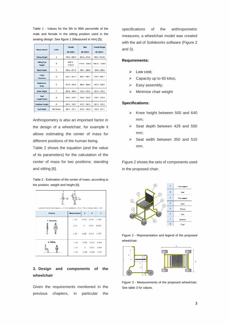
Given the requirements mentioned in the
previous chapters, in particular the
specifications of the anthropometric
measures, a wheelchair model was created
with the aid of Solidworks software (Figure 2
and 3).
Requirements:
Low cost;
Capacity up to 60 kilos;
Easy assembly;
Minimize chair weight
Specifications:
Knee height between 500 and 640
mm;
Seat depth between 429 and 550
mm;
Seat width between 350 and 510
mm.
Figure 2 shows the sets of components used
in the proposed chair.
Figure 2 - Representation and legend of the proposed
wheelchair.
Figure 3 - Measurements of the proposed wheelchair.
See table 3 for values.
4
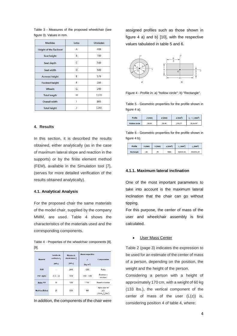
Table 3 - Measures of the proposed wheelchair (see
figure 3). Values in mm.
4. Results
In this section, it is described the results
obtained, either analytically (as in the case
of maximum lateral slope and reaction in the
supports) or by the finite element method
(FEM), available in the Simulation tool [7],
(serves for more detailed verification of the
results obtained analytically).
4.1. Analytical Analysis
For the proposed chair the same materials
of the model chair, supplied by the company
MMM, are used. Table 4 shows the
characteristics of the materials used and the
corresponding components.
Table 4 - Properties of the wheelchair components [8],
[9].
In addition, the components of the chair were
assigned profiles such as those shown in
figure 4 a) and b) [10], with the respective
values tabulated in table 5 and 6.
Figure 4 - Profile in: a) "hollow circle"; b) "Rectangle".
Table 5 - Geometric properties for the profile shown in
figure 4 a).
Table 6 - Geometric properties for the profile shown in
figure 4 b).
4.1.1. Maximum lateral inclination
One of the most important parameters to
take into account is the maximum lateral
inclination that the chair can go without
tipping.
For this purpose, the center of mass of the
user and wheelchair assembly is first
calculated.
User Mass Center
Table 2 (page 3) indicates the expression to
be used for an estimate of the center of mass
of a person, depending on the position, the
weight and the height of the person.
Considering a person with a height of
approximately 170 cm, with a weight of 60 kg
(133 lbs.), the vertical component of the
center of mass of the user (L(z)) is,
considering position 4 of table 4, where:
5
A = 0.334, B = -0.004 and C = 7.327
From table 2:
𝐿(𝑧) = [0,334 × 170] + [−0,004 × 133]
+ 7,327 =
= 63,58 𝑐𝑚 = 635.8 𝑚𝑚
Table 1 (page3) shows that the value of
letter A (for "Total range 5-95%") varies
between 795.0 and 972.82 mm, that is,
865.5 mm, and it is known from Table 3
(page 4), that the height of the seat of the
proposed chair is 700 mm.
Thus, from Figure 5, the center of mass of
the used (𝑪𝒖), from the ground, is given by:
Figure 5 - Schematic representation of the location of
the user's center of mass.
𝑌𝑢 = 865,5 − 635,8 = 229,7𝑚𝑚
𝑪𝒖 = 700 + 229,7 = 𝟗𝟐𝟗, 𝟕𝒎𝒎
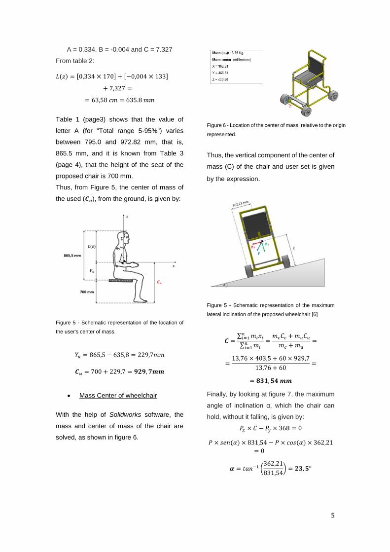
Mass Center of wheelchair
With the help of Solidworks software, the
mass and center of mass of the chair are
solved, as shown in figure 6.
Thus, the vertical component of the center of
mass (C) of the chair and user set is given
by the expression.
Figure 5 - Schematic representation of the maximum
lateral inclination of the proposed wheelchair [6]
𝑪 =∑ 𝑚𝑖𝑥𝑖
𝑛𝑖=1
∑ 𝑚𝑖𝑛𝑖=1
=𝑚𝑐𝐶𝑐 + 𝑚𝑢𝐶𝑢
𝑚𝑐 + 𝑚𝑢
=
=13,76 × 403,5 + 60 × 929,7
13,76 + 60=
= 𝟖𝟑𝟏, 𝟓𝟒 𝒎𝒎
Finally, by looking at figure 7, the maximum
angle of inclination α, which the chair can
hold, without it falling, is given by:
𝑃𝑥 × 𝐶 − 𝑃𝑦 × 368 = 0
𝑃 × 𝑠𝑒𝑛(𝛼) × 831,54 − 𝑃 × 𝑐𝑜𝑠(𝛼) × 362,21
= 0
𝜶 = 𝑡𝑎𝑛−1 (362,21
831,54) = 𝟐𝟑, 𝟓ᵒ
Figure 6 - Location of the center of mass, relative to the origin
represented.
6
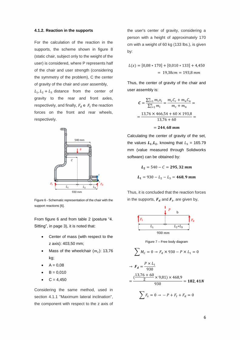
4.1.2. Reaction in the supports
For the calculation of the reaction in the
supports, the scheme shown in figure 8
(static chair, subject only to the weight of the
user) is considered, where P represents half
of the chair and user strength (considering
the symmetry of the problem), C the center
of gravity of the chair and user assembly,
𝐿1, 𝐿2 + 𝐿3 distance from the center of
gravity to the rear and front axles,
respectively, and finally, 𝐹𝑑 e 𝐹𝑡 the reaction
forces on the front and rear wheels,
respectively.
Figure 6 - Schematic representation of the chair with the
support reactions [6].
From figure 6 and from table 2 (posture “4.
Sitting”, in page 3), it is noted that:
Center of mass (with respect to the
z axis): 403,50 mm;
Mass of the wheelchair (𝑚𝑐): 13,76
kg;
A = 0,08
B = 0,010
C = 4,450
Considering the same method, used in
section 4.1.1 "Maximum lateral inclination",
the component with respect to the z axis of
the user's center of gravity, considering a
person with a height of approximately 170
cm with a weight of 60 kg (133 lbs.), is given
by:
𝐿(𝑥) = [0,08 ∗ 170] + [0,010 ∗ 133] + 4,450
= 19,38𝑐𝑚 = 193,8 𝑚𝑚
Thus, the center of gravity of the chair and
user assembly is:
𝑪 =∑ 𝑚𝑖𝑥𝑖
𝑛𝑖=1
∑ 𝑚𝑖𝑛𝑖=1
=𝑚𝑐𝐶𝑐 + 𝑚𝑢𝐶𝑢
𝑚𝑐 + 𝑚𝑢
=
=13,76 × 466,54 + 60 × 193,8
13,76 + 60=
= 𝟐𝟒𝟒, 𝟔𝟖 𝒎𝒎
Calculating the center of gravity of the set,
the values 𝑳𝟏,𝑳𝟐, knowing that 𝐿3 = 165.79
mm (value measured through Solidworks
software) can be obtained by:
𝑳𝟐 = 540 − 𝐶 = 𝟐𝟗𝟓, 𝟑𝟐 𝒎𝒎
𝑳𝟏 = 930 − 𝐿2 − 𝐿3 = 𝟒𝟔𝟖, 𝟗 𝒎𝒎
Thus, it is concluded that the reaction forces
in the supports, 𝑭𝒅 and 𝑭𝒕, are given by,
Figure 7 – Free body diagram
∑ 𝑀𝐶 = 0 → 𝐹𝑑 × 930 − 𝑃 × 𝐿1 = 0
→ 𝑭𝒅 =𝑃 × 𝐿1
930
=(13,76 + 60
2× 9,81) × 468,9
930= 𝟏𝟖𝟐, 𝟒𝟏𝑵
∑ 𝐹𝑥 = 0 → − 𝑃 + 𝐹𝑡 + 𝐹𝑑 = 0
7
→ 𝑭𝒕 = (13,76 + 60
2× 9,81) − 165,88 =
= 𝟏𝟗𝟓, 𝟗𝟏 𝑵
4.2. Finite Element Structural Analysis
4.2.1. Analysis of the wheelchair
Before analysis, it is necessary to define the
boundary conditions of the problem. In figure
10 a) and b) the structure with the respective
constraints is shown: for the front wheels (𝑼𝒛
= 0) and for the rear wheels (𝑼𝒙 = 𝑼𝒚= 𝑼𝒛=
0), as well as the location of the application
of the respective wheels forces, through an
analytical vision and through Solidworks
software (uses solid 3D finite elements).
Figure 8 – Boundary conditions and loading in the chair
structure a) free body diagram; b) Solidworks software.
For the load case, a force with an intensity of
P = 147.15 N (corresponding to the
mathematical division of the total force
exerted by the user on the 4 constituent
components of the seat) was used.
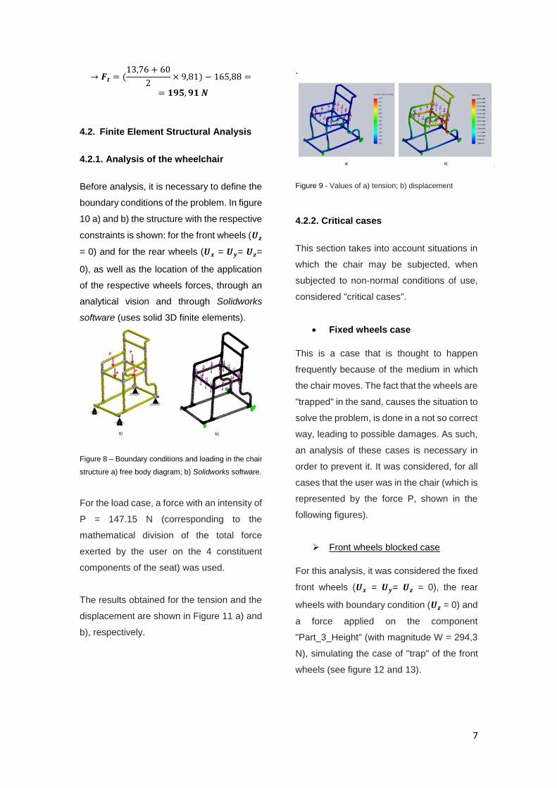
The results obtained for the tension and the
displacement are shown in Figure 11 a) and
b), respectively.
.
Figure 9 - Values of a) tension; b) displacement
4.2.2. Critical cases
This section takes into account situations in
which the chair may be subjected, when
subjected to non-normal conditions of use,
considered "critical cases".
Fixed wheels case
This is a case that is thought to happen
frequently because of the medium in which
the chair moves. The fact that the wheels are
"trapped" in the sand, causes the situation to
solve the problem, is done in a not so correct
way, leading to possible damages. As such,
an analysis of these cases is necessary in
order to prevent it. It was considered, for all
cases that the user was in the chair (which is
represented by the force P, shown in the
following figures).
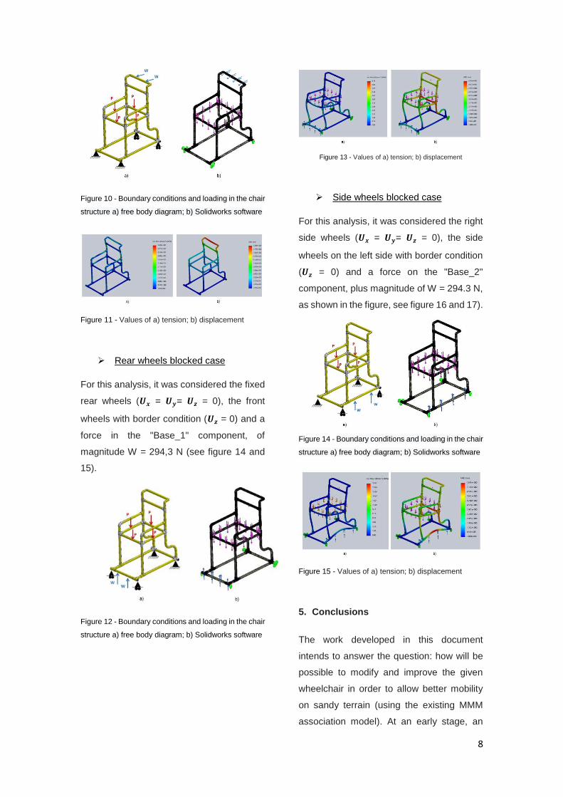
Front wheels blocked case
For this analysis, it was considered the fixed
front wheels (𝑼𝒙 = 𝑼𝒚= 𝑼𝒛 = 0), the rear
wheels with boundary condition (𝑼𝒛 = 0) and
a force applied on the component
"Part_3_Height" (with magnitude W = 294,3
N), simulating the case of "trap" of the front
wheels (see figure 12 and 13).
8
Figure 10 - Boundary conditions and loading in the chair
structure a) free body diagram; b) Solidworks software
Figure 11 - Values of a) tension; b) displacement
Rear wheels blocked case
For this analysis, it was considered the fixed
rear wheels (𝑼𝒙 = 𝑼𝒚= 𝑼𝒛 = 0), the front
wheels with border condition (𝑼𝒛 = 0) and a
force in the "Base_1" component, of
magnitude W = 294,3 N (see figure 14 and
15).
Figure 12 - Boundary conditions and loading in the chair
structure a) free body diagram; b) Solidworks software
Figure 13 - Values of a) tension; b) displacement
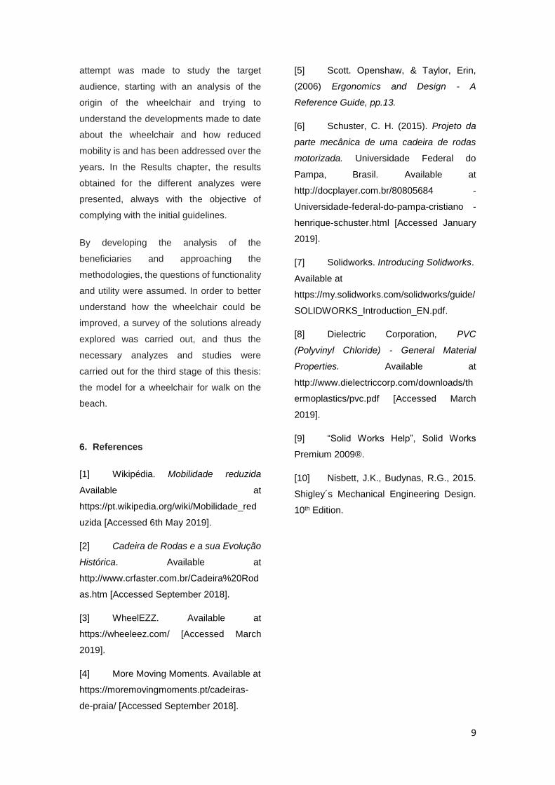
Side wheels blocked case
For this analysis, it was considered the right
side wheels (𝑼𝒙 = 𝑼𝒚= 𝑼𝒛 = 0), the side
wheels on the left side with border condition
(𝑼𝒛 = 0) and a force on the "Base_2"
component, plus magnitude of W = 294.3 N,
as shown in the figure, see figure 16 and 17).
Figure 14 - Boundary conditions and loading in the chair
structure a) free body diagram; b) Solidworks software
Figure 15 - Values of a) tension; b) displacement
5. Conclusions
The work developed in this document
intends to answer the question: how will be
possible to modify and improve the given
wheelchair in order to allow better mobility
on sandy terrain (using the existing MMM
association model). At an early stage, an
9
attempt was made to study the target
audience, starting with an analysis of the
origin of the wheelchair and trying to
understand the developments made to date
about the wheelchair and how reduced
mobility is and has been addressed over the
years. In the Results chapter, the results
obtained for the different analyzes were
presented, always with the objective of
complying with the initial guidelines.
By developing the analysis of the
beneficiaries and approaching the
methodologies, the questions of functionality
and utility were assumed. In order to better
understand how the wheelchair could be
improved, a survey of the solutions already
explored was carried out, and thus the
necessary analyzes and studies were
carried out for the third stage of this thesis:
the model for a wheelchair for walk on the
beach.
6. References
[1] Wikipédia. Mobilidade reduzida
Available at
https://pt.wikipedia.org/wiki/Mobilidade_red
uzida [Accessed 6th May 2019].
[2] Cadeira de Rodas e a sua Evolução
Histórica. Available at
http://www.crfaster.com.br/Cadeira%20Rod
as.htm [Accessed September 2018].
[3] WheelEZZ. Available at
https://wheeleez.com/ [Accessed March
2019].
[4] More Moving Moments. Available at
https://moremovingmoments.pt/cadeiras-
de-praia/ [Accessed September 2018].
[5] Scott. Openshaw, & Taylor, Erin,
(2006) Ergonomics and Design - A
Reference Guide, pp.13.
[6] Schuster, C. H. (2015). Projeto da
parte mecânica de uma cadeira de rodas
motorizada. Universidade Federal do
Pampa, Brasil. Available at
http://docplayer.com.br/80805684 -
Universidade-federal-do-pampa-cristiano -
henrique-schuster.html [Accessed January
2019].
[7] Solidworks. Introducing Solidworks.
Available at
https://my.solidworks.com/solidworks/guide/
SOLIDWORKS_Introduction_EN.pdf.
[8] Dielectric Corporation, PVC
(Polyvinyl Chloride) - General Material
Properties. Available at
http://www.dielectriccorp.com/downloads/th
ermoplastics/pvc.pdf [Accessed March
2019].
[9] “Solid Works Help”, Solid Works
Premium 2009®.
[10] Nisbett, J.K., Budynas, R.G., 2015.
Shigley´s Mechanical Engineering Design.
10th Edition.