Embed Size (px)
Citation preview

Powador-proLOG
Operating instructions

Operating Instructions Powador-proLOG_EN Page 3
Manual
Operating Instructions
Powador-proLOG
1 About this documentation ......................................5
1.1 Other applicable documents ...................................5
1.2 Retention of documents ..........................................5
1.3 Symbols used in this document ...............................5
1.4 CE marking ............................................................5
1.5 Name plate ............................................................5
2 Safety instructions and regulations ........................6
3 Notes on installation and operation ........................7
3.1 Intended use ..........................................................7
3.2 Factory warranty and liability ..................................7
3.3 Service ...................................................................7
4 Technical Data ........................................................8
5 Installation ...........................................................10
5.1 Determining the installation location.....................10
5.2 Installing the unit .................................................10
5.2.1 Powador-proLOG S ...............................................10
5.2.2 Powador-proLOG M / XL ......................................10
5.3 Service fl ap ..........................................................10
5.4 Connections .........................................................10
5.4.1 Voltage supply .....................................................10
5.4.2 GSM antenna (XL GSM/GPRS) .............................. 11
5.4.3 Powador-go (M / XL) ............................................ 11
5.4.4 Analogue/ISDN modem (XL) .................................12
5.4.5 24 V supply ..........................................................12
5.4.6 Ethernet ...............................................................12
5.4.7 RS485 connection ...............................................13

Page 4 Operating Instructions Powador-proLOG_EN
5.4.8 Digital output D0 .................................................15
5.4.9 Analogue/digital inputs ........................................15
5.5 KACO Power Control ...........................................17
5.6 Pin assignment .....................................................18
5.7 Jumper switch (M/XL only) ....................................18
6 Start-Up ...............................................................19
6.1 Procedure .............................................................19
6.2 Using the Powador-proLOG with Powador-web.....19
6.3 Using the Powador-proLOG without Powador-web .......................................................19
6.4 Display menu and status LEDs ..............................19
6.4.1 Meaning of the four status LEDs ...........................19
6.4.2 Display menu .......................................................20
6.4.3 Display menu structure: description of the menu items ...............................21
6.5 Powador-proLOG XL with GSM/GPRS modem .......23
6.5.1 General information .............................................23
6.5.2 Inserting a SIM card .............................................23
7 Establishing a Connection.....................................25
7.1 Hardware and software requirements ...................25
7.2 Direct connection to a Powador-proLOG over a network (Ethernet) .....................................25
7.3 Establishing a connection to a Powador-proLOG by modem .................................26
7.4 Powador-web .......................................................29
8 Menu Description .................................................30
8.1 General ................................................................30
8.2 Online values........................................................32
8.2.1 Analogue/digital ...................................................32
8.2.2 Current sensors ....................................................33
8.2.3 Inverter overview .................................................33
8.2.4 Inverter details .....................................................33
8.3 Status...................................................................33
8.3.1 System messages .................................................33
8.3.2 Inverters ..............................................................34
8.4 Confi guration .......................................................34
8.4.1 System data .........................................................34
8.4.2 Standard contact..................................................35
8.4.3 Date/Time ............................................................35
8.5 Admin monitoring ................................................35
8.5.1 Network ...............................................................35
8.5.2 Contact addresses ................................................37
8.5.3 Switching output ..................................................37
8.5.4 System messages .................................................38
8.5.5 Inverters ..............................................................38
8.5.6 Formulas ..............................................................38
8.5.7 Status alarms .......................................................39
8.6 Admin measurement ............................................39
8.6.1 Analogue channels ...............................................39
8.6.2 Digital channels ...................................................40
8.6.3 Extension modules ..............................................40
8.6.4 Current sensors ....................................................40
8.6.5 Inverters ..............................................................40
8.6.6 Energy of digital channels ....................................40
8.6.7 Energy of inverters ...............................................41
8.6.8 Time synchronisation ...........................................41
8.6.9 Active power and idle power control) (XL) ............41
9 Confi guration Example .........................................41
9.1 Analogue channels ...............................................42
9.1.1 Voltage input ........................................................42
9.1.2 Current input ........................................................42
9.2 Digital inputs ........................................................42
9.3 Alarm criterion .....................................................42
9.3.1 Basic principle of monitoring .................................43
9.3.2 Setting parameters for the measuring device ........43
9.4 Programming criteria using the example of an inverter comparison .....................................44
9.5 List of code designations ......................................45
10 Update .................................................................46
10.1 Update with card reader .......................................46
10.1.1 General information .............................................46
10.1.2 Instructions .........................................................46
10.2 Update via FTP .....................................................48
10.2.1 General information ............................................48
10.2.2 Instructions .........................................................48
Contents

Operating Instructions Powador-proLOG_EN Page 5
1 About this documentationThe following notes guide you through all of the documenta-tion. Additional documents are applicable in conjunction with these operating instructions.
1.1 Other applicable documentsWhen installing the data logger, be sure to observe all assem-bly and installation instructions for components and other parts of the system. These instructions are delivered together with the respective components and other parts of the system.
1.2 Retention of documentsPass these operating instructions on to the system operator. The system operator is to retain the documents. The instructions must be available whenever they are needed.
1.3 Symbols used in this documentWhen installing the data logger, observe the safety instruc-tions included in these installation instructions.
High voltage!
Read the manual
1.4 CE markingThe CE marking is used to document that the Powador-pro-LOG data logger shown on the name plate fulfi ls the funda-mental requirements of the following relevant directives: – Directive relating to electromagnetic compatibility (Council Directive 2004/108/EC)
– Low voltage directive (Council Directive 2006/95/EC)
1.5 Name plateThe name plate showing the exact designation of the unit is located on the left side of the housing.
Section 1 About th is Documentat ion
ATTENTIONRead the manualWe assume no liability for any damage caused by failure to observe these instructions.
ATTENTIONFailure to observe a warning indicated in this manner may lead to damage to property.
NOTE
Useful information and notes.
IMPORTANTFailure to observe this information may result in operat-ing diffi culty or impaired functionality.
DANGER
Failure to observe a warning indicated in this manner will lead directly to serious bodily injury or death.
ACTION
This symbol indicates that a certain action is required.

Page 6 Operating Instructions Powador-proLOG_EN
2 Safety Instructions and Regulations
Standards and regulationsIEC 60364-7-712:2002:Requirements for special installations or locations – Solar photovoltaic (PV) power supply systems.
Technical rulesThe installation must be suited to the on-site conditions and comply with local regulations and technical rules.
Accident prevention regulations
– The monitoring system for photovoltaic systems may only be connected by qualifi ed specialists.
– Cables must be disconnected from all power sources before being connected to or disconnected from the system.
– Read the manual and familiarise yourself with the unit prior to operation
– Damaged units must be removed from operation immedi-ately and inspected by a qualifi ed specialist.
– The unit is to be opened by a qualifi ed specialistonly.
– The safety of the operator and the unit cannot be guaran-teed if the operator does not adhere to the safety instruc-tions.
The proper and safe operation of this unit requires proper transportation, storage, assembly and installation, as well as careful operation and maintenance.
Transportation
The Powador-proLOG is subjected to extensive testing and inspections at our test facility. Only by doing so can we ensure the high quality of our products. Our data loggers leave our factory in proper electrical and mechanical condition. Special packaging ensures that materials are not damaged during transportation. However, damage may still occur during trans-port. The shipping company is responsible in such cases.
Thoroughly inspect the data logger upon delivery. Immedi-ately notify the responsible shipping company if you discover any damage to the packaging which indicates that the data logger may have been damaged or if you discover any visible damage to the data logger.
If necessary, KACO new energy GmbH will assist you. Damage reports must be received by the shipping company in writing within six days following receipt of the goods.
When transporting the data logger, only the original packag-ing is to be used, as this ensures safe transport.
Section 2 · Safety Inst ruct ions and Regulat ions
DANGER
Danger due to lethal voltages.
Lethal voltages are present within the unit and on the power supply lines. Therefore, only authorised electri-cians may install and open the unit.
ATTENTION
Risk of damage due to improper modifi cations.Do not attempt to open or modify the data logger.

Operating Instructions Powador-proLOG_EN Page 7
3 Notes on installation and operation
3.1 Intended useThe Powador-proLOG is used for system monitoring of a pho-tovoltaic system. It records the currents, voltages, temperatures, power and yields of every individual inverter, as well as the values of the externally connected sensors.The Powador-proLOG is built according to the state of the art and recognised safety rules. Nevertheless, improper use may cause hazards for the operators or result in damage to the units. Any other or additional use of the device is deemed improper. The manufacturer/supplier is not liable for damage caused by such use. Damage caused by improper use is at the sole risk of the operator.Intended use also includes adherence to the operating instruc-tions.
3.2 Factory warranty and liabilityKACO new energy GmbH grants a warranty of two years on the Powador-proLOG starting from the date of shipment by KACO new energy GmbH.
During this time, KACO new energy GmbH guarantees the proper function of the units and to undertake repairs at the factory free of charge in the event of a defect for which we are responsible.
Contact your specialty dealer if your unit exhibits a defect or fault during the warranty period.
Warranty claims are excluded in the following cases:
– Use of the units in ways not intended – Improper installation or installation that does not comply with standards
– Improper operation – Operating the unit with defective protective equipment – Unauthorised modifi cations to the units orrepair attempts
– Infl uence of foreign objects or force majeure (lightning, overvoltage, severe weather, fi re)
– Failure to observe the relevant safety regulations – Transport damage
All warranty claims must be handled at the premises of KACO new energy GmbH. Where possible, the unit must be returned in its original or equivalent packaging. The costs for these ser-vices cannot be borne by KACO new energy GmbH.KACO new energy GmbH will only perform warranty services if the defective unit is returned to KACO new energy GmbH
together with a copy of the invoice which was issued to the user by the dealer. The name plate on the unit must be fully legible. If these requirements are not fulfi lled, KACO new energy GmbH reserves the right to deny warranty services.
3.3 ServiceStarting with the product development phase, we place a great deal of importance on ensuring the quality and longev-ity of our data loggers.
However, in spite of all quality assurance measures, faults may occur in rare cases. In such cases, KACO new energy GmbH will provide you with the maximum pos-sible support. KACO new energy GmbH will make every effort to remedy such faults in an expeditious mannerand with a minimum of bureaucracy.In such cases, please contact our service department directly.
Telephone: +49(0)7132-3818-680e-Mail [email protected]
So that your enquiry can be dealt with more quickly, please always have the serial number (A) and hardware serial number (B) of your data logger to hand. Both numbers can be found on the name plate on the left-hand side of the housing (see fi gure below).
Section 3 · Notes on Insta l la t ion and Operat ion
A
B
Page 8 Operating Instructions Powador-proLOG_EN
Section 4 · Technica l Data
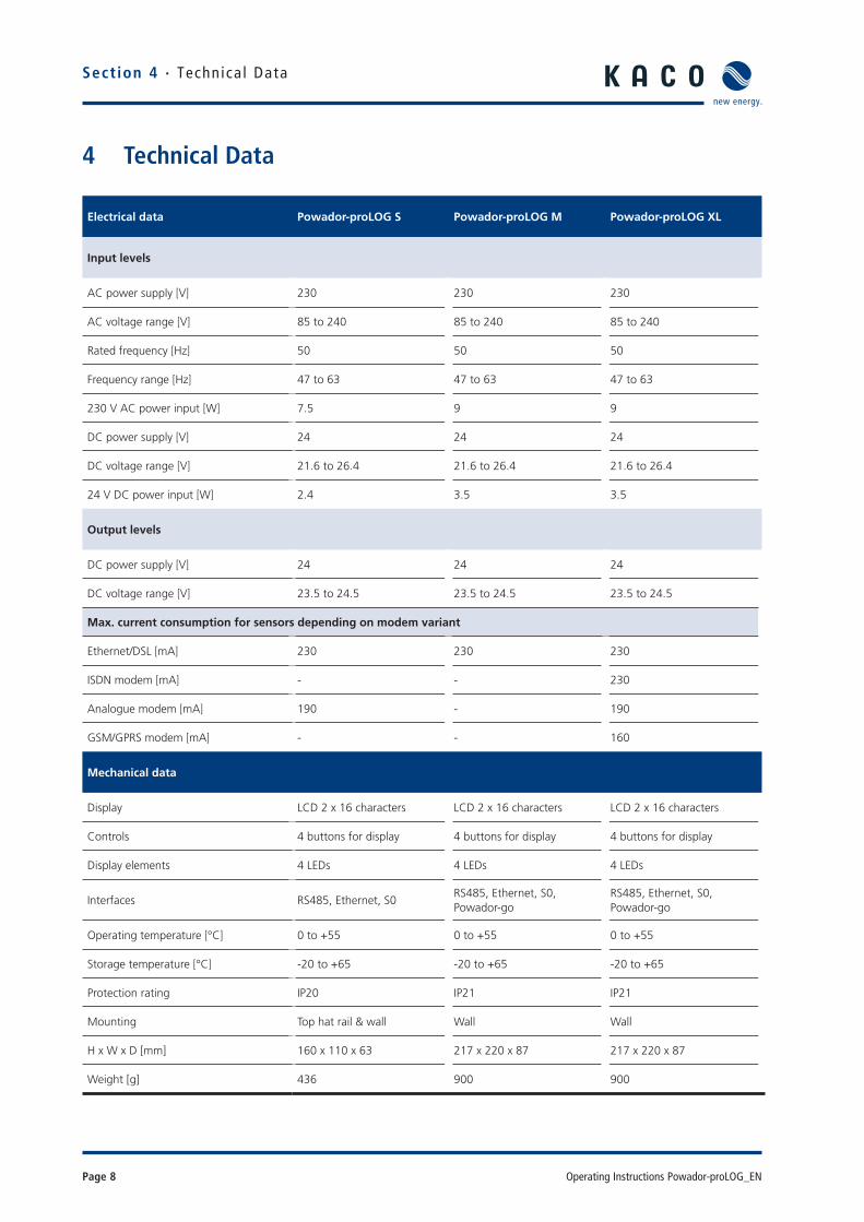
Electrical data Powador-proLOG S Powador-proLOG M Powador-proLOG XL
Input levels
AC power supply [V] 230 230 230
AC voltage range [V] 85 to 240 85 to 240 85 to 240
Rated frequency [Hz] 50 50 50
Frequency range [Hz] 47 to 63 47 to 63 47 to 63
230 V AC power input [W] 7.5 9 9
DC power supply [V] 24 24 24
DC voltage range [V] 21.6 to 26.4 21.6 to 26.4 21.6 to 26.4
24 V DC power input [W] 2.4 3.5 3.5
Output levels
DC power supply [V] 24 24 24
DC voltage range [V] 23.5 to 24.5 23.5 to 24.5 23.5 to 24.5
Max. current consumption for sensors depending on modem variant
Ethernet/DSL [mA] 230 230 230
ISDN modem [mA] - - 230
Analogue modem [mA] 190 - 190
GSM/GPRS modem [mA] - - 160
Mechanical data
Display LCD 2 x 16 characters LCD 2 x 16 characters LCD 2 x 16 characters
Controls 4 buttons for display 4 buttons for display 4 buttons for display
Display elements 4 LEDs 4 LEDs 4 LEDs
Interfaces RS485, Ethernet, S0RS485, Ethernet, S0, Powador-go
RS485, Ethernet, S0, Powador-go
Operating temperature [°C] 0 to +55 0 to +55 0 to +55
Storage temperature [°C] -20 to +65 -20 to +65 -20 to +65
Protection rating IP20 IP21 IP21
Mounting Top hat rail & wall Wall Wall
H x W x D [mm] 160 x 110 x 63 217 x 220 x 87 217 x 220 x 87
Weight [g] 436 900 900
4 Technical Data

Operating Instructions Powador-proLOG_EN Page 9
Sect ion 4 · Technica l Data
Connections Powador-proLOG S Powador-proLOG M Powador-proLOG XL
Analogue inputs
Number of 1 1 4
DC voltage measurement [V] 0 to 10 (max. 24) 0 to 10 (max. 24) 0 to 10 (max. 24)
DC current measurement [mA] 0 to 20 (max. 40/3 V) 0 to 20 (max. 40/3 V) 0 to 20 (max. 40/3 V)
Resistance measurement PT1000 PT1000 PT1000
Measuring accuracy1% of the end value(0.1 V/0.2 mA)
1% of the end value(0.1 V/0.2 mA)
1% of the end value(0.1 V/0.2 mA)
Digital inputs
Number of 1 1 4
S0 pulse input (DC) [V]Low: 0 to 7High: 9 to 24
Low: 0 to 7High: 9 to 24
Low: 0 to 7High: 9 to 24
– Powered exclusively by the unit’s internal power supply – Can be confi gured as a status input – Potential-free contacts – S0 interface specifi cation conforms to DIN 43864
Digital output
Number of 1 1 1
S0 optocoupler (DC) Max. 70 V/50 mA Max. 70 V/50 mA Max. 70 V/50 mA
Display elements 4 LEDs 4 LEDs 4 LEDs
Interfaces – Can be confi gured as an alarm or pulse output – Observe the polarity
Communication
Ethernet 100 MBit (RJ45) 100 MBit (RJ45) 100 MBit (RJ45)
Analogue modem (PSTN)* 1 (RJ12) - 1 (RJ12)
ISDN modem* - - 1 (RJ12)
GSM/GPRS modem - -SIM card slotAntenna (FME)
*Depending on Powador-proLOG variant

Page 10 Operating Instructions Powador-proLOG_EN
Section 5 · Ins ta l la t ion
5 Installation5.1 Determining the installation locationInstall the Powador-proLOG near a telephone or Ethernet connection and a 230 V grid connection. To prevent damage to the Powador-proLOG or the building’s electrical system,keep the following points in mind when you choosean installation location: – The Powador-proLOG must not be installed outdoorsor in damp areas. The unit must be protected from moisture and direct sunlight.
– The ambient temperature must be between 0°C and +55°C.
– There must not be any building installations (e.g. power, gas or water lines) around the drill holes.
– The Powador-proLOG should be placed on a level surface to prevent damage to the housing.
5.2 Installing the unit
5.2.1 Powador-proLOG S
The unit is suitable for mounting on a top hat rail (size 35 mm). To make it easy to attach the housing, use a clamping device to snap it onto (or release it from) the hat rail.
5.2.2 Powador-proLOG M / XLThe unit is suitable for wall mounting. Use thesketch below to mark the drill holes. The distance between the screws on the mounting bracket and the wall should be approx. 3 mm.Hang the Powador-proLOG on the screw heads, and then pull down. Now secure thePowador-proLOG with a third screw in the lower part of the unit.
Drill hole sketch (lengths in mm)
5.3 Service fl apThe Powador-proLOG may only be operated when the ser-vice fl ap is closed. However, the service fl ap must be openedfor the purpose of connecting the voltage supply, the network connection (Ethernet) or sensors.
There are two versions of the service fl ap: Spherical closure or screw-type closure
5.4 Connections
Powador-proLOG M/XL
Powador-proLOG S
5.4.1 Voltage supply
The Powador-proLOG is powered by an integrated power supply. The grid connection (230 V) should be protected by a separate fuse(e.g. B6A). The power supply provides 24 V,e.g. to power a solar sensor.
Powador-proLOG M/XL Powador-proLOG S
ATTENTIONThe 230 V AC grid connection of the Powador-proLOG must always be disconnected from the power supply (by pulling out the plug) before opening the service fl ap
ATTENTION
Always make sure that the service fl ap is closed while the unit is in operation, i.e. that the spherical closure is fi rmly in place or that the service fl ap is screwed tight.
115
92
167 225
230
110217
220
167
92
S
160 mm
110
mm
Operating Instructions Powador-proLOG_EN Page 11
Sect ion 5 · Ins ta l la t ion
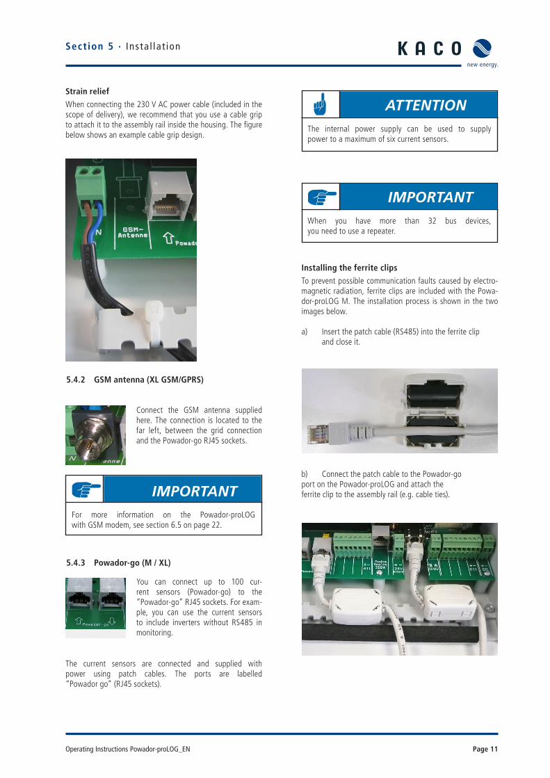
Strain relief
When connecting the 230 V AC power cable (included in the scope of delivery), we recommend that you use a cable grip to attach it to the assembly rail inside the housing. The fi gure below shows an example cable grip design.
5.4.2 GSM antenna (XL GSM/GPRS)
5.4.3 Powador-go (M / XL)
The current sensors are connected and supplied with power using patch cables. The ports are labelled“Powador go” (RJ45 sockets).
Installing the ferrite clipsTo prevent possible communication faults caused by electro-magnetic radiation, ferrite clips are included with the Powa-dor-proLOG M. The installation process is shown in the two images below.
a) Insert the patch cable (RS485) into the ferrite clip and close it.
b) Connect the patch cable to the Powador-go port on the Powador-proLOG and attach the ferrite clip to the assembly rail (e.g. cable ties).
Connect the GSM antenna supplied here. The connection is located to the far left, between the grid connection and the Powador-go RJ45 sockets.
You can connect up to 100 cur-rent sensors (Powador-go) to the“Powador-go” RJ45 sockets. For exam-ple, you can use the current sensors to include inverters without RS485 in monitoring.
IMPORTANTFor more information on the Powador-proLOGwith GSM modem, see section 6.5 on page 22.
ATTENTIONThe internal power supply can be used to supplypower to a maximum of six current sensors.
IMPORTANTWhen you have more than 32 bus devices,you need to use a repeater.
Page 12 Operating Instructions Powador-proLOG_EN
5.4.4 Analogue/ISDN modem (XL)Depending on the unit type, the Powador-proLOG units are equipped with either an internal analogue or an internal ISDN modem. The cable connection is included in the scope of deliv-ery. – Before you install the unit, use a telephone to test the analogue/ISDN telephone connection in both directions (incoming and outgoing connections).
– Use the included cable to connect the unit to the TAE socket/NTBA.
– If you need to extend the cable, make sure that the contacts are secure and the polarity is correct..
Powador-proLOG XL Powador-proLOG S (analogue only)
5.4.5 24 V supply
Powador-proLOG M/XL Powador-proLOG S
5.4.6 EthernetAll Powador-proLOG models are equipped with a network connection to connect the unit to an Ethernet network.
Powador-proLOG M/XL Powador-proLOG S
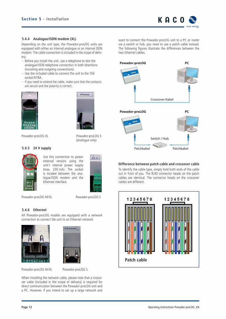
When installing the network cable, please note that a crosso-ver cable (included in the scope of delivery) is required for direct communication between the Powador-proLOG unit and a PC. However, if you intend to set up a large network and
want to connect the Powador-proLOG unit to a PC or router via a switch or hub, you need to use a patch cable instead. The following fi gures illustrate the differences between the two Ethernet cables.
POWADOR pro LOG
MADE IN GERMANY
XL
Crossover-Kabel
Powador-proLOG PC
POWADOR pro LOG
MADE IN GERMANY
XL
Powador-proLOG PC
Switch / Hub
Patchkabel Patchkabel
Difference between patch cable and crossover cableTo identify the cable type, simply hold both ends of the cable out in front of you. The RJ45 connector heads on the patch cables are identical. The connector heads on the crossover cables are different.
Use this connection to power external sensors using the unit's internal power supply (max. 230 mA). The socket is located between the ana-logue/ISDN modem and the Ethernet interface.
Patch cable
Sect ion 5 · Ins ta l la t ion
Operating Instructions Powador-proLOG_EN Page 13
To prevent possible communication faults caused by electromagnetic radiation, ferrite clips are includedwith the Powador-proLOG M. The instal-lation process is described in 5.4.3Powador-go (M / XL).
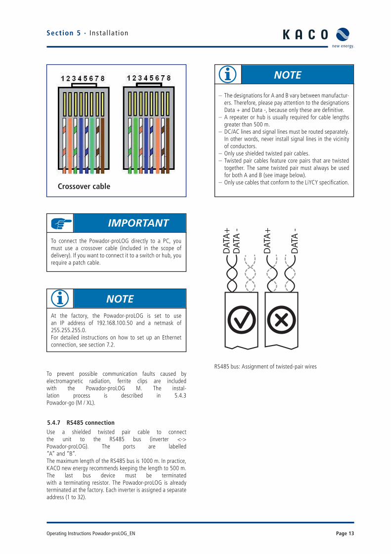
5.4.7 RS485 connection Use a shielded twisted pair cable to connectthe unit to the RS485 bus (inverter <-> Powador-proLOG). The ports are labelled“A” and “B”.The maximum length of the RS485 bus is 1000 m. In practice, KACO new energy recommends keeping the length to 500 m.The last bus device must be terminatedwith a terminating resistor. The Powador-proLOG is already terminated at the factory. Each inverter is assigned a separate address (1 to 32).
RS485 bus: Assignment of twisted-pair wires
Crossover cable
IMPORTANT
To connect the Powador-proLOG directly to a PC, you must use a crossover cable (included in the scope of delivery). If you want to connect it to a switch or hub, you require a patch cable.
NOTE
– The designations for A and B vary between manufactur-ers. Therefore, please pay attention to the designations Data + and Data -, because only these are defi nitive.
– A repeater or hub is usually required for cable lengths greater than 500 m.
– DC/AC lines and signal lines must be routed separately. In other words, never install signal lines in the vicinity of conductors.
– Only use shielded twisted pair cables. – Twisted pair cables feature core pairs that are twisted together. The same twisted pair must always be used for both A and B (see image below).
– Only use cables that conform to the LiYCY specifi cation.
NOTEAt the factory, the Powador-proLOG is set to usean IP address of 192.168.100.50 and a netmask of 255.255.255.0.For detailed instructions on how to set up an Ethernet connection, see section 7.2.
Section 5 · Ins ta l la t ion
Page 14 Operating Instructions Powador-proLOG_EN
Section 5 · Ins ta l la t ion
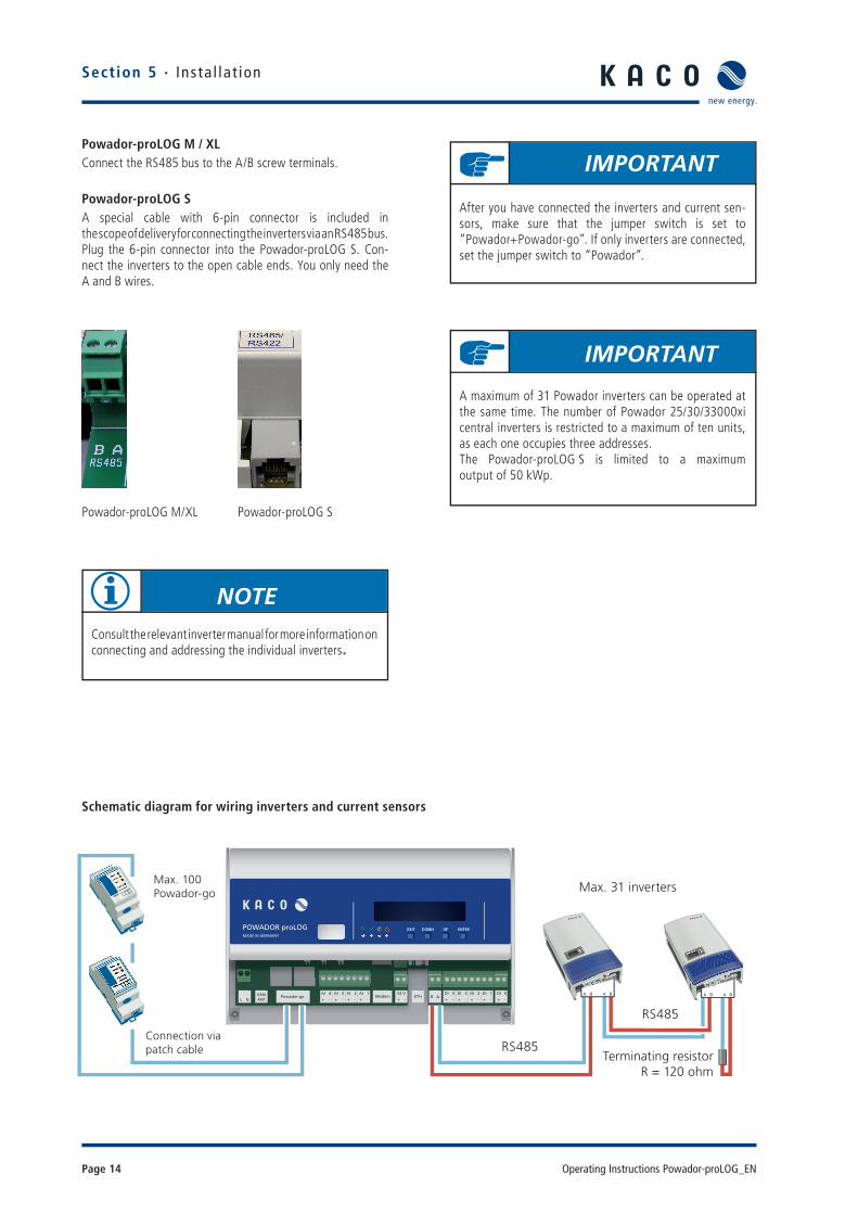
Powador-proLOG M / XLConnect the RS485 bus to the A/B screw terminals.
Powador-proLOG SA special cable with 6-pin connector is included inthe scope of delivery for connecting the inverters via an RS485 bus.Plug the 6-pin connector into the Powador-proLOG S. Con-nect the inverters to the open cable ends. You only need the A and B wires.
Powador-proLOG M/XL Powador-proLOG S
IMPORTANT
A maximum of 31 Powador inverters can be operated at the same time. The number of Powador 25/30/33000xi central inverters is restricted to a maximum of ten units, as each one occupies three addresses.The Powador-proLOG S is limited to a maximumoutput of 50 kWp.
NOTE
Consult the relevant inverter manual for more information onconnecting and addressing the individual inverters.
IMPORTANT
After you have connected the inverters and current sen-sors, make sure that the jumper switch is set to “Powador+Powador-go”. If only inverters are connected, set the jumper switch to “Powador”.
Schematic diagram for wiring inverters and current sensors
POWADOR proLOGMADE IN GERMANY
EXIT DOWN UP ENTER
GSMANT
ETHAI 4
-+
AI 3
-+
AI 2
-+
AI 1
-+
24 V
-+AB
NL
DI 4
-+
DI 3
-+
DI 2
-+
DI 1
-+
DI 0
-+Powador-go Modem
Max. 100Powador-go
Connection viapatch cable RS485
RS485
Max. 31 inverters
Terminating resistorR = 120 ohm

Operating Instructions Powador-proLOG_EN Page 15
5.4.8 Digital output D0The digital output can be used as an alarm output to control signalling devices or as a pulse output to connect a display.
Powador-proLOG M/XL Powador-proLOG S
Connecting a display to D0
Connecting a signalling device to D0
5.4.9 Analogue/digital inputsThe unit is equipped with four (XL) or one (S, M) analogue input(s), which are designed for a voltage measurement of 0 to 10 V.
Powador-proLOG XL Powador-proLOG S
Counter pulses (maximum frequency: 14 Hz) can be recorded using four (XL) or one (S, M) digital counter input(s). An inter-face in accordance with the S0 specifi cation must be available.
Powador-proLOG XL Powador-proLOG S
Section 5 · Ins ta l la t ion
NOTE
To confi gure this function, connect to the Powador-pro-LOG and make the required settings via -> “Admin moni-toring > Switching output” in your browser.
ATTENTION
The output is designed as an optocoupler output (N/O contact) and must therefore be connected to an external voltage supply, if necessary. The maximum load is 50 mA.
NOTEThe analogue inputs can be optionally converted forcurrent measurement or resistance measurement.You do this in the confi guration menu of the Powador-proLOG (Admin-Messung -> Admin measurement > Ana-logue channels).
ATTENTIONIncorrect polarity or using an external voltage supply greater than 24 V can destroy the measuring input. The 24-V supply is available starting at terminal DI+.
ATTENTION
Incorrect polarity or using a voltage supply greater than 12 V can destroy the measuring input.
NOTE
The digital inputs can be optionally converted for status evaluation.This means that the Powador-proLOG can evaluate switching states 0 or 1 (N/C or N/O contact).This must be set up using the confi guration fi lesfor the Powador-proLOG.Please contact the KACO new energy hotline.
Powador-proLOG
+ -D0+ -
24V + -
Signalgeber Powador-proLOG
Impulseingang
Anzeigedisplay Powador-proLOG
D0+ - + -
Powador-proLOG Display
Page 16 Operating Instructions Powador-proLOG_EN
Section 5 · Ins ta l la t ion
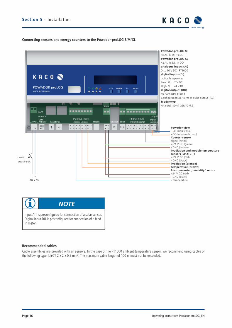
Connecting sensors and energy counters to the Powador-proLOG S/M/XL
Recommended cablesCable assemblies are provided with all sensors. In the case of the PT1000 ambient temperature sensor, we recommend using cables of the following type: LiYCY 2 x 2 x 0.5 mm². The maximum cable length of 100 m must not be exceeded.
POWADOR proLOGMADE IN GERMANY
EXIT DOWN UP ENTER
Ethernet
GSMANT
ETH
Analoge EingängePowador-go Digitale EingängeRS485230V ACGSM-Antenne
DigitalAusgang
intern
Modem
AI 4
-+
AI 3
-+
AI 2
-+
AI 1
-+
24 V
-+AB
NL
DI 4
-+
DI 3
-+
DI 2
-+
DI 1
-+
DI 0
-+i s Powador-view- S0-Impuls (blau)+ S0-Impuls (braun)
ZählersensorSignal (weiss)+ 24 V DC (grün)- GND (braun)
Einstrahlungssensor mit Modultemperaturfühler (Si12TC-T)+ 24 V DC (rot)- GND (schwarz)Einstrahlung (orange)Temperatur (braun)
Umgebungstemperatursensor+ 24 V DC (rot)- GND (schwarz)Temperatur
Leitungs-schutzschalter B6 A
Powador-proLOG M1x AI, 1x DI, 1x DO
Powador-proLOG XL4x AI, 4x DI, 1x DO
Analoge Eingänge (AI)0 … 10 V DC | PT1000
Digitale Eingänge (DI)Optisch getrenntLow: 0 … 7 V DCHigh: 9 … 24 V DC
Digitaler Ausgang (DO)S0 nach DIN 43 864Konfiguration als Alarm- oder Impulsausgang (S0)
ModemtypenAnalog | ISDN | GSM/GPRS
NL
230 V AC
NOTE
Input AI1 is preconfi gured for connection of a solar sensor. Digital input DI1 is preconfi gured for connection of a feed-in meter.
Powador-proLOG M1x AI, 1x DI, 1x DOPowador-proLOG XL4x AI, 4x DI, 1x DOanalogue inputs (AI)0 … 10 V DC | PT1000digital inputs (DI)optically seperatedLow: 0 … 7 V DCHigh: 9 … 24 V DCdigital output (DO)S0 nach DIN 43 864Confi guration as Alarm or pulse output (S0)ModemtypAnalog | ISDN | GSM/GPRS
breaker B6A
digital inputs
digital
output
GSM
antennaanalogue inputs
Powador view- S0-Impuls(blue)+ S0-Impulse (brown)Counter sensorSignal (white)+ 24 V DC (green)- GND (brown)Irradiation and module temperature sensors (SI12TC-T)+ 24 V DC (red)- GND (black)irradiation (orange)Temperature (brown)Environmental „humidity“ sensor+24 V DC (red)- GND (black)- Temperature
circuit

Operating Instructions Powador-proLOG_EN Page 17
5.5 KACO Power Control Since 1 January 2009 when the German Renewable Ener-gies Act (EEG) was passed, PV systems in excess of 100 kW have been subject to remote-controlled power regulation. In principle, each individual unit in a network with other units can become a system of this size. Therefore, every Powador inverter supports power reduction.
KACO new energy achieves this power reduction function (KACO power control) by combining the Powador-proLOG XL unit with a radio ripple control receiver. These units enable the power supply company to reduce the power of the system as required. For this, the following levels are possible: 0%, 30%, 60% or 100% of the rated AC power of the inverter. When you specify 30 % or 60 %, the inverter limits the power to 30 % or 60 %. With a setting of 0 %, the inverter disconnects from the grid, and 100% is used for normal grid feed mode.
When the power supply company requests a reduction in the power, the Powador-proLOG receives the corresponding signal via the radio ripple control receiver. The Powador-pro-LOG then forwards the information to all connected inverters as a command via the RS485 interface. After a period of fi ve minutes without any signal from the power supply company, the inverters return to normal operation.
Connection
The radio ripple control receiver is connected to the Powador-proLOG XL, which is mandatory for the use of KACO power control. You do not have to make any changes to the inverter in order to use the KACO power control function, since it is integrated into the inverter as standard. It is activated and confi gured using the Powador-proLOG XL web server or the integrated display on the Powador-proLOG XL.
KACO Power-Control
Adapter board
Radio ripple control receiverRelaiscontact
Section 5 · Ins ta l la t ion
ATTENTIONTo use the KACO power control function, you must insert the adapter board. This is included in the scope of deliv-ery of each Powador-proLOG XL unit. In other words, you must remove the standard plug connector and insert the adapter board instead. Now connect the radio ripple con-trol receiver to the adapter board.
supplies230 V AC
Page 18 Operating Instructions Powador-proLOG_EN
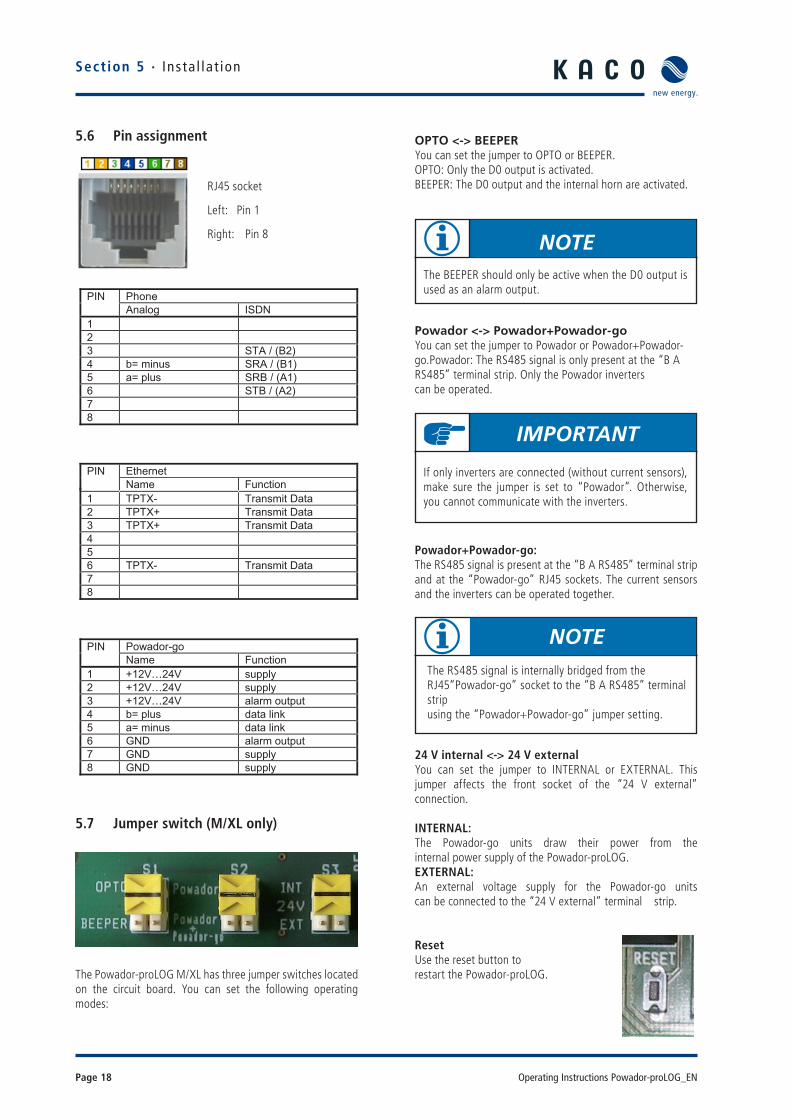
OPTO <-> BEEPERYou can set the jumper to OPTO or BEEPER.OPTO: Only the D0 output is activated.BEEPER: The D0 output and the internal horn are activated.
Powador <-> Powador+Powador-goYou can set the jumper to Powador or Powador+Powador-go.Powador: The RS485 signal is only present at the “B A RS485” terminal strip. Only the Powador inverters can be operated.
Powador+Powador-go:The RS485 signal is present at the “B A RS485” terminal strip and at the “Powador-go” RJ45 sockets. The current sensors and the inverters can be operated together.
24 V internal <-> 24 V externalYou can set the jumper to INTERNAL or EXTERNAL. This jumper affects the front socket of the “24 V external”connection.
INTERNAL: The Powador-go units draw their power from theinternal power supply of the Powador-proLOG.EXTERNAL: An external voltage supply for the Powador-go units can be connected to the “24 V external” terminal strip.
ResetUse the reset button torestart the Powador-proLOG.
5.6 Pin assignment
5.7 Jumper switch (M/XL only)
The Powador-proLOG M/XL has three jumper switches located on the circuit board. You can set the following operating modes:
NOTEThe RS485 signal is internally bridged from the RJ45“Powador-go” socket to the “B A RS485” terminal stripusing the “Powador+Powador-go” jumper setting.
RJ45 socket
Left: Pin 1
Right: Pin 8
Phone PINAnalog ISDN
123 STA / (B2) 4 b= minus SRA / (B1) 5 a= plus SRB / (A1) 6 STB / (A2) 78
EthernetPINName Function
1 TPTX- Transmit Data 2 TPTX+ Transmit Data 3 TPTX+ Transmit Data 456 TPTX- Transmit Data 78
Powador-go PINName Function
1 +12V…24V supply 2 +12V…24V supply 3 +12V…24V alarm output4 b= plus data link 5 a= minus data link 6 GND alarm output7 GND supply 8 GND supply
NOTEThe BEEPER should only be active when the D0 output is used as an alarm output.
IMPORTANT
If only inverters are connected (without current sensors), make sure the jumper is set to “Powador”. Otherwise, you cannot communicate with the inverters.
Section 5 · Ins ta l la t ion

Operating Instructions Powador-proLOG_EN Page 19
6 Start-Up6.1 Procedure
1. Switch on the Powador-proLOG Connect the supply voltage to switch on the unit. After the supply voltage has beenconnected, the “Power” LED must remain lit.
2. Check the status LEDs The status LED provides information about the unit’s status after it has been started up:
Status LED is off ->System is starting up
Status LED is fl ashing steadily -> System is ready
3. This is the most important part of start-up. Once the system has started up (Power LED is lit/Status LED is fl ashing), you should connect to the Powador-proLOG with your computer to check whether all inverters are answering over the RS485 line and whether all connected sensors are providing data. See section 7 (“Establishing a Connection”) of this manual for information on how to connect to the Powador-proLOG with your computer.
6.2 Using the Powador-proLOG with Powador-web
1. You do not have to confi gure the data logger on site. You must ensure that the inverters and sensors have been connected correctly. Make sure that the telephone connection (analogue, ISDN) and the Internet connection (Ethernet) or SIM card (GSM/ GPRS) are functioning correctly. It must be possible to access the data logger using a PC/laptop (assign IP address). In the case of network devices (Ethernet), you should also have the free TeamViewer software installed on your PC/laptop to ensure trouble-free service. As soon as you have managed to meet these requirements, please contact the
KACO new energy monitoring service.2. Once KACO new energy has confi rmed that your data logger is communicating with the portal please send the completed application form to the monitoring service. You can download the application form from our wesite: "www.kaco-newenergy.de".
6.3 Using the Powador-proLOG without Powador-web1. Once you have successfully connected to the Powador-proLOG, you should confi gure the unit to meet your requirements (inverter, analogue/digital channels, alarm notifi cation and data transmission).
2. You can use the “Installation Wizard”) to confi gure and check the measured data of the Powador-pro LOG. It will guide you through the installation process one step at a time. You can also use the “Expert page” to confi gure and check measured data. For more information, see section 8 (“Menu Description”).
6.4 Display menu and status LEDs
6.4.1 Meaning of the four status LEDs"Power” LED Remains lit: the unit is supplied with powerIs not lit: there is a fault in the voltage supply
"Status” LED Is not lit: the system is just starting up (boot phase)Flashing: the system loaded successfully (normal operation)
"Connect” LED Is not lit: currently there is no connection via analogue modem, ISDN or GSMFlashing: the connection to the remote station is being estab-lishedRemains lit: the connection was successfully established
"Alarm” LED Is not lit: normal operationRemains lit: the unit issues an alarm signal via alarm output D0 (provided it was appropriately confi gured)
NOTE
The system needs about two minutes to be completely initialised. This process is similar to starting up (booting) a PC. The completion of the boot phase is indicated by the status LED: The status LED is off during the boot phase and only starts to fl ash after it is completed.
ATTENTIONMake sure that everything is properly connected(polarity) and that all inverters are addressed (RS485 address). For more information, see the inverter manual.
Section 6 · Star t -up
NOTE
You can use what is known as the "posbox" function to test the connection to the Powador-web. To do this go to Admin monitoring » Network » Postbox).

Page 20 Operating Instructions Powador-proLOG_EN
6.4.2 Display menuThe integrated display allows you to make settings (e.g. IP address for the Powador-proLOG) or search for inverters during installation.You can also query current measured values and stored energy yields while the unit is operating.
Navigating through the display menu:
EXIT: - Cancel input - Go back one menu level DOWN: - Select a menu item below this point - Lower the number
UP: - Select a menu item above this point - Increase the number
ENTER: - Confi rm input - Go down one menu level - Go to the next menu level
Section 6 · Star t -up

Operating Instructions Powador-proLOG_EN Page 21
6.4.3 Display menu structure: Description of the menu items
Rechte Passwort
0300tsaGInstallateur 0020Administrator 0010
Overview Ethernet Current IP address
GSM/GPRS Field strength
Settings Communication Ethernet DHCP
Static IP address
Subnet mask
Gateway
Modem / ISDN / GSM Local IP address
Remote IP address
Subnet mask
ISDN-MSN
PIN-Code
Call acceptance
Data logger Inverter settings
Current values Analogue values
System Energy of DI Current power
Yield today
Yield yesterday
Monthly yield
Annual yield
Total yield
Alarms/Faults Communication
System error
Current subnet mask
Current gateway
Language Deutsch
English
Francais
Espanol
Italiano
Set factory settings
Start scan
Power Control
AI1
AI2
AI3
AI4
Digital values
Current sensors
Inverters
DI4
DI1
DI2
DI3
Address 1
Address x
Adresse 1
Adresse x
Modem faults
System file is missing
System alarms Alarm list
Reset local alarms
Hardware AI / DI fault
OCS does´t respond
Inverter doesn`t respond
Energy Inverters Current power
Daily energy
Previous day´s energy
Energy for the month
Annual energy
total energy
Section 6 · Star t -up

Page 22 Operating Instructions Powador-proLOG_EN
Description of the menu items:
Overview You can see the current TCP/IP settings for your Ethernet con-nection here. For GSM/GPRS units, you can also query the fi eld strength.
▲ Ethernet Current IP address: Shows the current IP address that is used in the LAN. • Current subnet mask: Shows the current subnet mask that is used in the LAN. • Current gateway: Shows the current gateway- that is used in the LAN.
▲ GSM/GPRS • Field strength: Indicates the fi eld strength.
SettingsIn the “Communication” section, you can make numerous communication settings, e.g. change IP addresses or set the PIN code for the GSM card. You can set the respective local language in the second section, which is the “Language” sec-tion. In the third section, which is the “Data logger” section, you can trigger an inverter scan and activate the power con-trol function. You can also reset the data logger to its factory settings.
▲ Communication • Ethernet → Boot protocol none: No boot protocol is used. DHCP (Dynamic Host Confi guration Protocol): A DHCP server assigns an IP address to the Powador-proLOG.
BOOTP (bootstrap protocol): The BOOTP server assigns an IP address to the Powador-proLOG.
RARP (Reverse Address Resolution Protocol): A RARP server assigns an IP address to the Powador-proLOG.
→ Static IP address: The IP address that is used when no boot protocol was selected. → Subnet mask: The subnet mask that is used when one was not assigned by the BOOTP/DHCP server.
→Gateway: The gateway that is used when one was not assigned by the BOOTP/DHCP server.
• Modem/ISDN/GSM → Local IP address: The IP address that the Powador-proLOG has in the WAN. → Remote IP address: The IP address that the caller must have on the WAN . → Subnet mask: The subnet mask in the WAN → MSN (ISDN only): MSN setting → PIN Code (GSM only): GSM pin setting
▲ Data logger Inverter settings • Start scan: Use this option to search for inverters.• Activate power control• Set factory settings Reset to factory settings. Current valuesThe current measured values are displayed here. Various que-ries are possible, depending on which units are connected.▲ Analogue values Shows the analogue measured values.▲ Digital values Shows the digital measured values.▲ Current sensors Shows the measured values for the current sensors▲ Inverters Shows the current power of the individual inverters.
SystemIn the “Power/Energy” section, you can read the current total power and the energy that is fed in during various time periods. The “Alarms/Faults” section shows messages about faults detected in the system.
▲ Energy of DI If at least one digital channel was selected to calculate the overall system power, the relevant measured value will be displayed in the following submenus. → Current power → Yield today → Yield yesterday → Monthly yield → Annual yield → Total yield
▲ Energy InvertersIf the inverters were selected to calculate the total system power and energy, the relevant measured value will be dis-played in the following submenus.
→ Current power → Daily energy → Previous day's energy → Energy for the month → Annual energy → Total energy
Section 6 · Star t -up

Operating Instructions Powador-proLOG_EN Page 23
▲ Alarms/Faults → Communication - Modem fault A fault occurred while establishing the modem connection → System error: - System fi le is missing A fi le that is needed by the system is missing. → System alarms -Alarm list A list of the system alarms that were triggered. - Reset local alarms Reset the local alarm at D0. → Hardware - AI/DI fault Analogue/digital input fault - OCS does not respond No reply from the current sensor - Inverter does not respond No reply from the inverter
Factory settings:
Network: IP address: 192.168.100.50 Subnet mask: 255.255.255.0
Modem: IP address: 192.168.200.1 Remote IP address: 192.168.200.51 Subnet mask: 255.255.255.255 Analogue :Call acceptance active ISDN: MSN deleted GSM: PIN code is 4321
Section 6 · Star t -up
6.5 Powador-proLOG XL with GSM/GPRS modem
6.5.1 General informationTo ensure optimum operation of the Powador-proLOG, we rec-ommend that you take advantage of the agreement that we offer. The costs for this agreement are passed on one to one.
The alternatively used GSM/GPRS data card must have the fol-lowing properties: – You should be able to call the data card using an analogue modem. For this reason, the card’s data telephone number is required. You usually receive another number for data traffi c from your grid operator.
– You must be able to send e-mail (with attachments). – The transfer rate is 9.6 kBit/s. – The card does not require storage space. – The data volume is approx. 100 kB per day, assuming the data is sent once per day by e-mail (without alarms).
– A CSD (Circuit Switched Data) data service must be acti-vated.
6.5.2 Inserting a SIM card
IMPORTANT
If you use a different contract, KACO new energy will not be able to provide you with support due to recurring prob-lems with the various network providers.
ATTENTIONBe sure to ground yourself before touching any of the electronic components.

Page 24 Operating Instructions Powador-proLOG_EN
1. Open the housingTo insert the SIM card, fi rst open the housing. To do so, remove the two housing screws on the front of the unit. The SIMcard slot is located at the rear of the connection box on the top part of the modem.
2. Insert the SIM cardWith the chip facing up, slide the SIM card into the holder. The card will lock automatically. To unlock it again, lightly push the SIM card forward.
3. Connect the antenna
The antenna connection is located in the connection area, next to the 230 V grid connection. Connect the included antenna here.
4. Start the Powador-proLOGOn delivery, the PIN number of the Powador-proLOG is 4321. The PIN numbers for the SIM card and thePowador-proLOG must be identical. If this is not the case, the card cannot be registered and will be blocked after a cer-tain period. Use the display to check and/or change the PIN number for the Powador-proLOG.
Once the Powador-proLOG has successfully started, you can read the reception status on the display:
Section 6 · Star t -up
Operating Instructions Powador-proLOG_EN Page 25
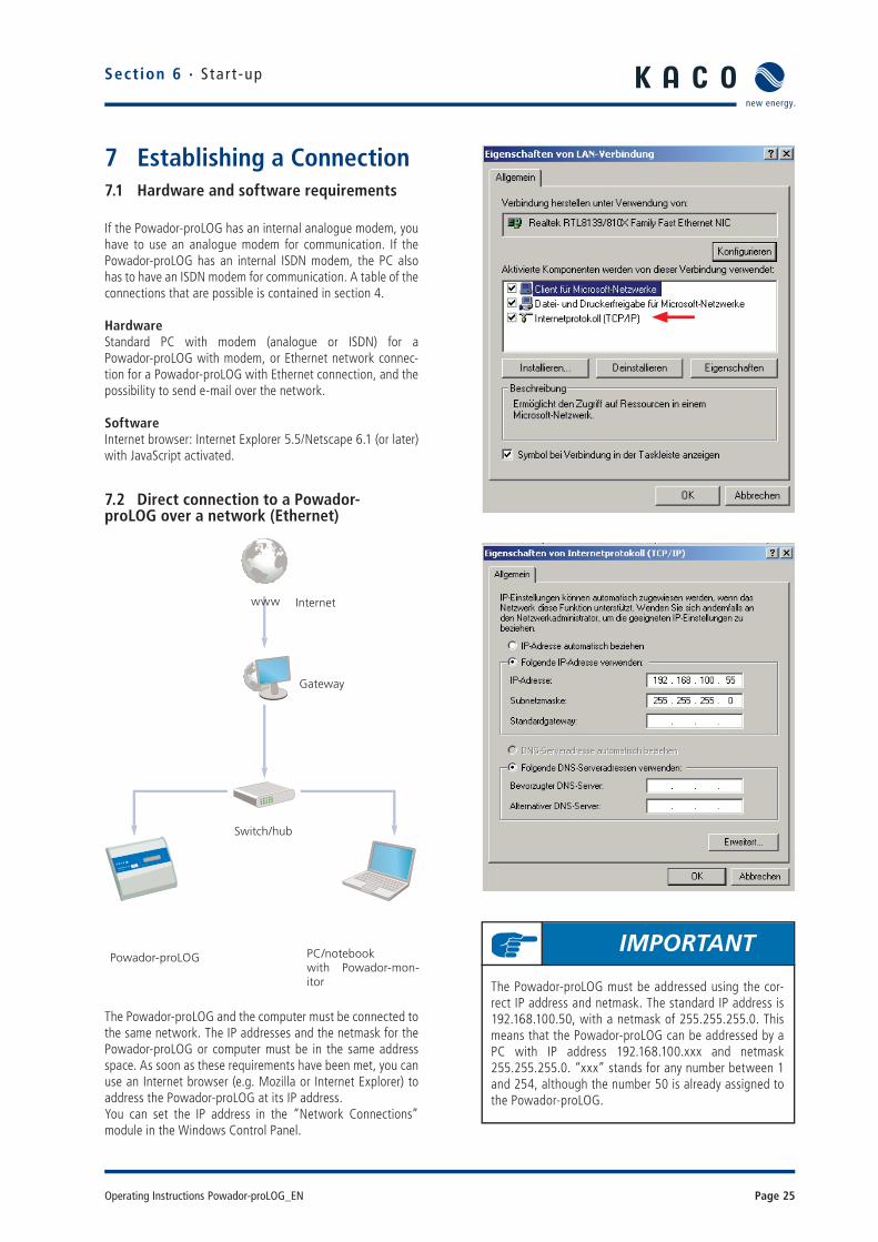
7 Establishing a Connection7.1 Hardware and software requirements
If the Powador-proLOG has an internal analogue modem, you have to use an analogue modem for communication. If the Powador-proLOG has an internal ISDN modem, the PC also has to have an ISDN modem for communication. A table of the connections that are possible is contained in section 4.
HardwareStandard PC with modem (analogue or ISDN) for aPowador-proLOG with modem, or Ethernet network connec-tion for a Powador-proLOG with Ethernet connection, and the possibility to send e-mail over the network.
SoftwareInternet browser: Internet Explorer 5.5/Netscape 6.1 (or later) with JavaScript activated.
7.2 Direct connection to a Powador- proLOG over a network (Ethernet)
The Powador-proLOG and the computer must be connected to the same network. The IP addresses and the netmask for the Powador-proLOG or computer must be in the same address space. As soon as these requirements have been met, you can use an Internet browser (e.g. Mozilla or Internet Explorer) to address the Powador-proLOG at its IP address. You can set the IP address in the “Network Connections” module in the Windows Control Panel.
Section 6 · Star t -up
IMPORTANT
The Powador-proLOG must be addressed using the cor-rect IP address and netmask. The standard IP address is 192.168.100.50, with a netmask of 255.255.255.0. This means that the Powador-proLOG can be addressed by a PC with IP address 192.168.100.xxx and netmask 255.255.255.0. “xxx” stands for any number between 1 and 254, although the number 50 is already assigned to the Powador-proLOG.
POWADOR pro LOG
MADE IN GERMANY
XL
Powador-proLOG PC/notebookwith Powador-mon-itor
Switch/hub
Gateway
Internetwww

Page 26 Operating Instructions Powador-proLOG_EN
Section 7 · Establ i sh ing a Connect ion
Example:IP address of the Powador-proLOG: 192.168.100.50IP address of the network card (computer): 192.168.100.55
You can change the Powador-proLOG’s settings for IP address, netmask and gateway via “Admin monitoring -> Network -> Settings”). Depending on your settings, the IP address may vary. In this case, enter the correct IP address in your browser instead of the standard address that is listed above.
7.3 Establishing a connection to a Powador-proLOG by modem
To connect to the Powador-proLOG from a PC, you have to set up a new dial-up connection. The instructions below are based on the example of Windows XP.
Windows XP
1. StepA suitable modem must already be connected to your PC and installed.Access the “Network Connections” menu item by selecting “Start -> Settings -> Control Panel”). Now select the “New Connection Wizard”.
2. StepSelect the “New Connection Wizard” and then click “Next”. Now select the “Connect to the Internet” menu item. In the next window, select “Set up my connection manually”. Select “Connect using a dial-up modem” in the following window.
IMPORTANT
After you have made changes, saved the settings, and restarted the unit, the Powador-proLOG can be reached using the new parameters.
IMPORTANTIf the Powador-proLOG has an internal analogue modem, you have to use an analogue modem or an ISDN modem with analogue simulation for communication. If the Pow-ador-proLOG has an internal ISDN modem, the PC also has to have an ISDN modem for communication.
POWADOR pro LOG
MADE IN GERMANY
XL
Powador-proLOG
GSM ortelephone network
Connection via modem
Powador-webvia KACO server
Internet connection
www

Operating Instructions Powador-proLOG_EN Page 27
3. StepPress the “Next” button to begin setting up yourconnection. First enter a name (of your choosing) which will be used later on to call up the connection. In the next window, enter the phone number for the Powador-proLOG.
In the window that follows, enter “admin” for both the user name and the password.
Enter “admin” for both the user name and the pass-word.
Sect ion 7 · Establ i sh ing a Connect ion
proLOG
NOTE
Check boxes 2 (“Make this the default Internet connec-tion”) and 3 (“Turn on Internet Connection Firewall for this connection”) should be deactivated, because they could disrupt operation.The following window is the fi nal step in setting up the connection.
proLOG
NOTE
When you enter the telephone number, remember to include any prefi xes that may be required to dial out. The most common dial-out prefi x is a preceding “0”.
Page 28 Operating Instructions Powador-proLOG_EN
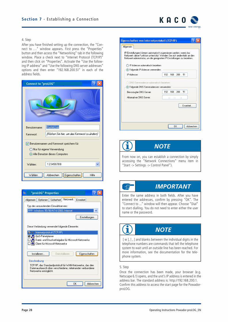
4. StepAfter you have fi nished setting up the connection, the “Con-nect to …” window appears. First press the “Properties” button and then access the “Networking” tab in the following window. Place a check next to “Internet Protocol (TCP/IP)” and then click on “Properties”. Activate the “Use the follow-ing IP address” and “Use the following DNS server addresses” options and then enter “192.168.200.51” in each of the address fi elds.
5. StepOnce the connection has been made, your browser (e.g. Netscape 6.1) opens, and the unit’s IP address is entered in the address bar. The standard address is: http://192.168.200.1.Confi rm this address to access the start page for the Powador-proLOG.
Section 7 · Establ i sh ing a Connect ion
Connect to “proLOG”
“proLOG” Properties
NOTE
From now on, you can establish a connection by simply accessing the “Network Connections” menu item in “Start -> Settings -> Control Panel”).
IMPORTANTEnter the same address in both fi elds. After you have entered the addresses, confi rm by pressing “OK”. The “Connect to ...” window will then appear. Choose “Dial” to start dialling. You do not need to enter either the user name or the password.
NOTE [ w ], [ , ] and blanks between the individual digits in the telephone numbers are commands that tell the telephone system to wait until an outside line has been reached. For more information, see the documentation for the tele-phone system.
Operating Instructions Powador-proLOG_EN Page 29
7.4 Powador-webPowador-web is an Internet portal that allows for a compre-hensive evaluation and visualisation of photovoltaic systems together with the Powador-proLOG. The password-protected portal provides you with secure and worldwide access to your system data.As administrator, you can confi gure which data is displayed.
Highlights Professional remote monitoring
Graphical presentation of measured values
Compatible with all operating systems
Automatic data transmission
Comprehensive alarm parameters
Alarm notifi cation via e-mail, fax or SMS (text mes-sage)
Summary of your systems for one farm
KACO new energy confi gures portal and data log-ger based on the application form(which is available at www.kaco-newenergy.de).
Low annual fee
Advantages of Powador-web Worldwide access to measured data
Satellite data updated daily
Basic data is the same for each user
Updates are made centrally
No installation necessary
Extremely high level of data security and availability
Hourly updates
Custom alarm notifi cation
The Powador-web Internet portal must be requested sepa-rately. Set-up and usage are subject to various costs. The application form is available for download from the KACO new energy website. To avoid your application being delayed, the application form must be completed in full. We have acti-vated a sample system at
http://www.kaco-newenergy.de
so that you can familiarise yourself with what Powador-web can do. A link to “KACO Plant 3” in Neckarsulm is located on the right-hand side of the homepage. Because this system is accessible to everyone, it has a limited range of functions.
Once Powador-web has been completely set up and is ready to use, KACO new energy will send you the access data for your system.
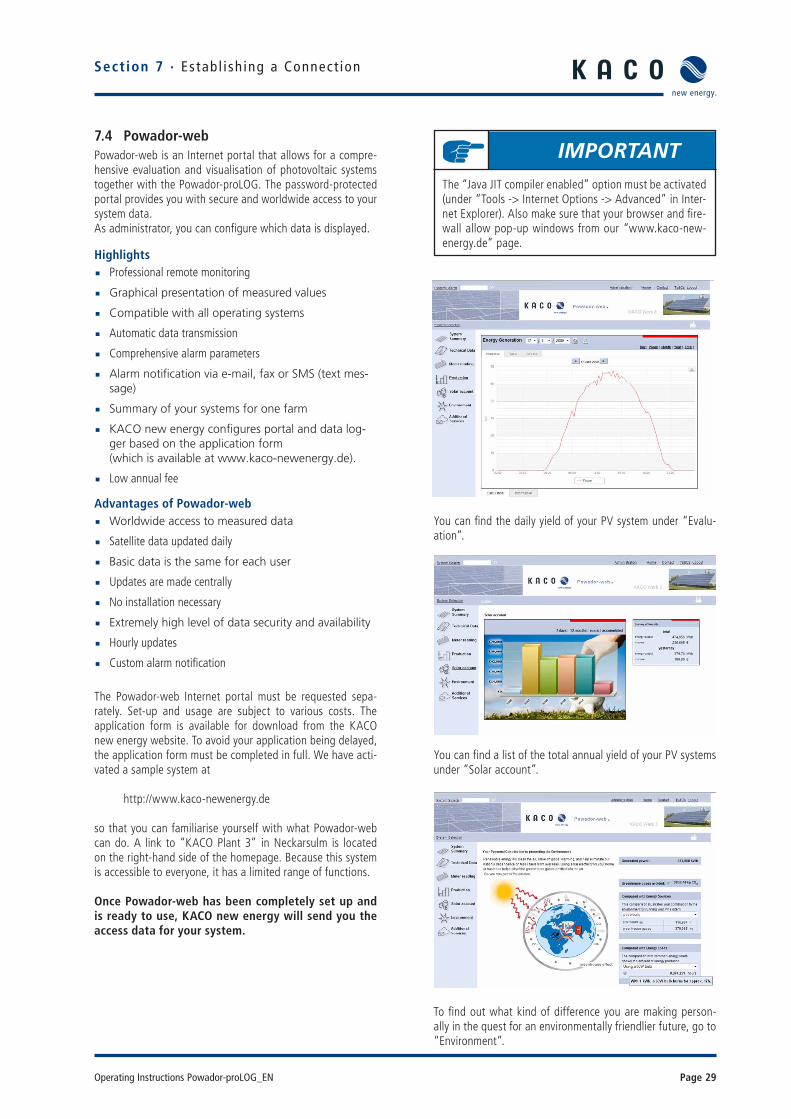
You can fi nd the daily yield of your PV system under “Evalu-ation”.
You can fi nd a list of the total annual yield of your PV systems under “Solar account”.
To fi nd out what kind of difference you are making person-ally in the quest for an environmentally friendlier future, go to “Environment”.
Section 7 · Establ i sh ing a Connect ion
IMPORTANTThe “Java JIT compiler enabled” option must be activated (under “Tools -> Internet Options -> Advanced” in Inter-net Explorer). Also make sure that your browser and fi re-wall allow pop-up windows from our “www.kaco-new-energy.de” page.

Page 30 Operating Instructions Powador-proLOG_EN
Section 8 · Menu Descr ipt ion
8 Menu DescriptionOnce you have established a dial-up or network con-nection, you can access the menu structure for thePowador-proLOG in your browser.
The Powador-proLOG’s Start Center is divided into two menu items:
- Installationsassistent (Installation Wizard)- Profi seite (Expert Page)
The Installation Wizard has been designed to make it as easy as possible for the user to set up the data logger. The installa-tion procedure comprises 14 steps. Help is provided for each step.
01 System time02 System data03 Contact data04 Connections05 Send data and alarms06 Test connections07 Measurement equipment: analogue08 Measurement equipment: digital09 Measurement equipment: inverter scan10 Measurement equipment: energy comparison confi gura-tion11 Test measurement equipment12 Monitoring13 Digital output14 Final report
The expert page is intended for experienced users.The following menu items show the start page:
• 8.1 General• 8.2 Online values• 8.3 Status• 8.4 Confi guration
The following additional menu items can be accessed by the administrator:
• 8.5 Admin monitoring and• 8.6 Admin measurement
8.1 GeneralThe start page shows the most important information for the system. Hardware: This section provides an overview of occupied channels and available bus devices.Monitoring: This section shows the last fault message that occurred, and when it occurred. The last data transmission is also shown. The fi eld strength is indicated for GSM/GPRS units.System parameters: These entries provide information about the connected photovoltaic system.
IMPORTANT
With a dial-up connection (modem), enter “http://192.168.200.1/” in your browser.For a network connection, enter the IP address (standard: http://192.168.100.50/) in your browser.
ATTENTIONChanges in this section can cause the data logger to mal-function. Consult your system administrator or KACO new energy GmbH before making changes.
NOTE
To log on to the unit as system administrator, access the dial-in page via “Allgemein -> Login“General -> Login”). The password is: ist02

Operating Instructions Powador-proLOG_EN Page 31
HTML menu
General Informa-tion
Online values Status Confi guration Admin monitoring Admin measure-ment
Logout Analogue/digital System messages System data Network » Analogue Channels
Start page Current sensors InvertersStandard con-tact
Contact addresses » Digital Channels
Powador-Argus Date/time Switching output Extension Modules
Inverter overview System messages Current sensors
Inverter details Inverters Powador-Argus
Active power/idle powercontrol
Powador-Argus Inverters
Formulas »Active power/idle powercontrol »
Status alarms » Energy of digital inputs
Website password Energy of inverters
Time synchronisation
Section 8 · Menu Descr ipt ion

Page 32 Operating Instructions Powador-proLOG_EN
8.2 Online values
This section shows various measured values from the sensors and counters that are connected to the analogue and digital inputs. If inverters are connected to the RS485 interface, you can also query the inverter values.
8.2.1 Analogue/digital
Sect ion 8 · Menu Descr ipt ion
Details of the digital inputs:
Example:
The system consists of two sub-systems, which have separate counters connected to the Powador-proLOG. To get the proper totals, activate the two sub-counters for consideration under “ Admin measurement -> Energy of digital channels”)
An overview of the system’s overall energy production is pro-vided here. You can defi ne how this overall total is calculated in the > Admin measurement -> Energy of digital channels”) section.
This section lists the measured values for each digital input.
Current power:The pulse constant is used to convert counter pulses to the corresponding power over a specifi ed period of time. (Power displayed in kW.)
Minimum:The lowest measured value for the current day
Details of the analogue inputs:
Maximum:The highest measured value for the current day
Counter reading:This column shows the overall total for the measured pulses. You can calibrate this display with the actual value on the energy counter. (See the “Admin measurement -> Digital channels”) menu item; displayed in kWh).
Analogue values are shown with channel number and desig-nation. The following information is provided:
Value:Current online value (updated every 10 seconds)
Minimum:The lowest measured value for the current day
Maximum:The highest measured value for the current day

Operating Instructions Powador-proLOG_EN Page 33
Sect ion 8 · Menu Descr ipt ion
8.2.2 Current sensors
If current sensors (Powador-go) are connected, the current measured values of the current sensors are shown here.
8.2.3 Inverter overview
If inverters are connected and properly addressed, current and accumulated measured values are shown here. Total yields are displayed in the “Total for all inverters” section. The “Overview of individual inverters”) section lists all con-nected inverters, including address, unit status, current feed-in power and daily yield that was reached at the time of the query. Each inverter address is linked to the inverter details.
8.2.4 Inverter details
This section shows all of the inverter’s measured values. You can only select one inverter at a time from the drop-down list.
8.3 Status
8.3.1 System messagesThis menu item provides an overview of the possible alarm statuses.
The measured value alarms result from the criteria speci-fi ed in “Admin monitoring -> Formulas -> Criteria 0-4”. The status overview lists the following information: – Designation:
The name that was defi ned in Formula -> Criterion”) is shown here. – Status:
Indicates whether the criterion is defi ned as active or inactive. – Upper limit:
This shows the current upper limit value for the monitoring criterion. – Actual value:
This shows the current actual value for the monitoring criterion. – Lower limit:
This shows the current lower limit value for the monitoring criterion. – Alarm counter:
This shows how often the criterion exceeded a limit value. – Sending status:
Indicates whether there are currently alarm messages that are waiting to be sent. – Information:
This shows when the last alarm occurred.
The system alarms relate to messages that are based on faults in the monitoring system. – Designation:
The reason for the error message is shown here. – Alarm type:
Information about the type of e-mail/fax alarm message. – Alarm destination:
Shows which contact the error message was sent to. – Alarm counter:
This shows how often the alarm was tripped. – Sending status:
Indicates whether there are currently alarm messages that are waiting to be sent. – Info Information:
This shows when the last alarm occurred.
The Sending status of e-mails status shows the sys-tem’s current status. For example, if e-mails are waiting to be sent, “busy” is shown in the “sendstate” fi eld. The normal status is “Ready to Send”.

Page 34 Operating Instructions Powador-proLOG_EN
Section 8 · Menu Descr ipt ion
8.3.2 Inverters
The “Fault messages” section shows when the last alarm message occurred, including alarm destination and mode of communication). The ”Brief information” section lists all con-nected inverters with their address and unit status.
8.4 Confi guration
8.4.1 System data
System data is required at various times. In the Powador-proLOG, the information is used on the title page to provide a quick system overview. The system data is provided in the “Admin monitoring -> Formulas”) section to defi ne fault messages.
This is where you enter data about the operator, the system power, the module types, orientation, etc. You can also make settings related to error message sending, scanning rate, and so forth.
– System designation: This entry appears on the start page and is included in all alarm messages. – Operator:
For documentation purposes only. – Installed power:
Used when calculating alarm criteria – Module area:
Used when calculating alarm criteria – Degree of effi ciency of modules):
Used when calculating alarm criteria – Degree of effi ciency of inverters:
Used when calculating alarm criteria – Number of sub-systems:
Used when calculating alarm criteria – Storage interval:
Data compression every 300, 600, 900, 1800, 3600 seconds – Orientation:
The system’s orientation – Angle of inclination:
The angle of inclination of the modules – Module type:
Module data – Inverter type:
e.g. Powador 5000xi – E-mail contact for sending data:
Destination for sending measured data – Data transmission: On/Off – Dial-out prefi x:
Number required to reach an outside line (depends on the telephone system) – Tone or pulse dialling:
Dialling method setting – Time-out (analogue modem):
Maximum time between two bell signals – Language:
You can choose between German and English. – Call acceptance: On/Off
You can limit call acceptance on the data logger to a specifi c time. More information can be found on the next page. – Bell signals (analogue modem)):
Number of bell signals until the Powador-proLOG answers – Contact for sending the daily fi le by fax):
The daily fi les can also be sent by fax at a specifi c time. Options: Inactive, Contacts 1-4), Standard contact.
Operating Instructions Powador-proLOG_EN Page 35
Sect ion 8 · Menu Descr ipt ion
Additional settings when call acceptance = “off”
– Start time for call acceptance: Time that the unit begins answering – Stop time for call acceptance:
Time that the unit stops answering – Bell signals (analogue modem)):
Number of bell signals until the Powador-proLOG answers – Time for call acceptance after reset):
Time (in seconds) indicating how long the unit can be reached for after a restart
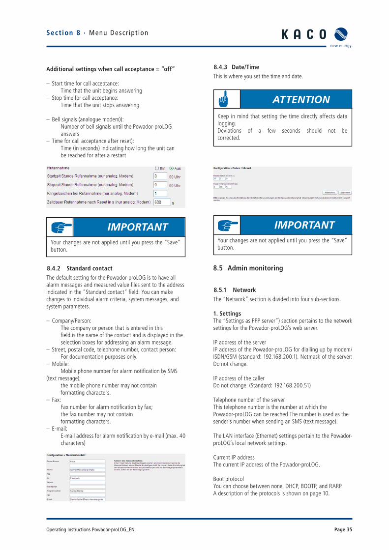
8.4.2 Standard contactThe default setting for the Powador-proLOG is to have all alarm messages and measured value fi les sent to the address indicated in the “Standard contact” fi eld. You can make changes to individual alarm criteria, system messages, and system parameters.
– Company/Person: The company or person that is entered in this fi eld is the name of the contact and is displayed in the selection boxes for addressing an alarm message. – Street, postal code, telephone number, contact person:
For documentation purposes only. – Mobile:
Mobile phone number for alarm notifi cation by SMS (text message); the mobile phone number may not contain formatting characters. – Fax:
Fax number for alarm notifi cation by fax; the fax number may not contain formatting characters. – E-mail:
E-mail address for alarm notifi cation by e-mail (max. 40 characters)
8.4.3 Date/TimeThis is where you set the time and date.
8.5 Admin monitoring
8.5.1 NetworkThe “Network” section is divided into four sub-sections.
1. SettingsThe “Settings as PPP server”) section pertains to the network settings for the Powador-proLOG’s web server.
IP address of the serverIP address of the Powador-proLOG for dialling up by modem/ISDN/GSM (standard: 192.168.200.1). Netmask of the server: Do not change.
IP address of the callerDo not change. (Standard: 192.168.200.51)
Telephone number of the serverThis telephone number is the number at which thePowador-proLOG can be reached The number is used as the sender’s number when sending an SMS (text message).
The LAN interface (Ethernet) settings pertain to the Powador-proLOG’s local network settings.
Current IP addressThe current IP address of the Powador-proLOG. Boot protocolYou can choose between none, DHCP, BOOTP, and RARP.A description of the protocols is shown on page 10.
IMPORTANTYour changes are not applied until you press the “Save” button.
ATTENTIONKeep in mind that setting the time directly affects data logging.Deviations of a few seconds should not be corrected.
IMPORTANTYour changes are not applied until you press the “Save” button.
Page 36 Operating Instructions Powador-proLOG_EN
Section 8 · Menu Descr ipt ion
Static IP addressIndicates the desired IP address when no boot protocol is used.
NetmaskThe subnet mask that is used if one has not beenassigned by the BOOTP/DHCP server.
GatewayThe gateway that is used when one was not assigned by the BOOTP/DHCP server.
– DNS server You can enter the DNS server in this fi eld. – DNS server
You can enter an alternate DNS server in this fi eld. The ISDN terminal adapter settings pertain to the Powador-proLOG’s ISDN settings. To use the unit on an ISDN exten-sion, enter the relevant connection number here.
MSNConnection number for the ISDN extension, which is usually a phone number without prefi x.The settings for testing the reporting methods are used to test the Powador-proLOG’s ability to make contact. The test can be conducted by e-mail, fax and SMS (text message).
Contact for the testThe contact for sending a test message. You can use the standard contact or specify one of the four contact addresses.Place a check next to the relevant fi elds to activate the desired form of contact (E-mail, Fax, or Text message).
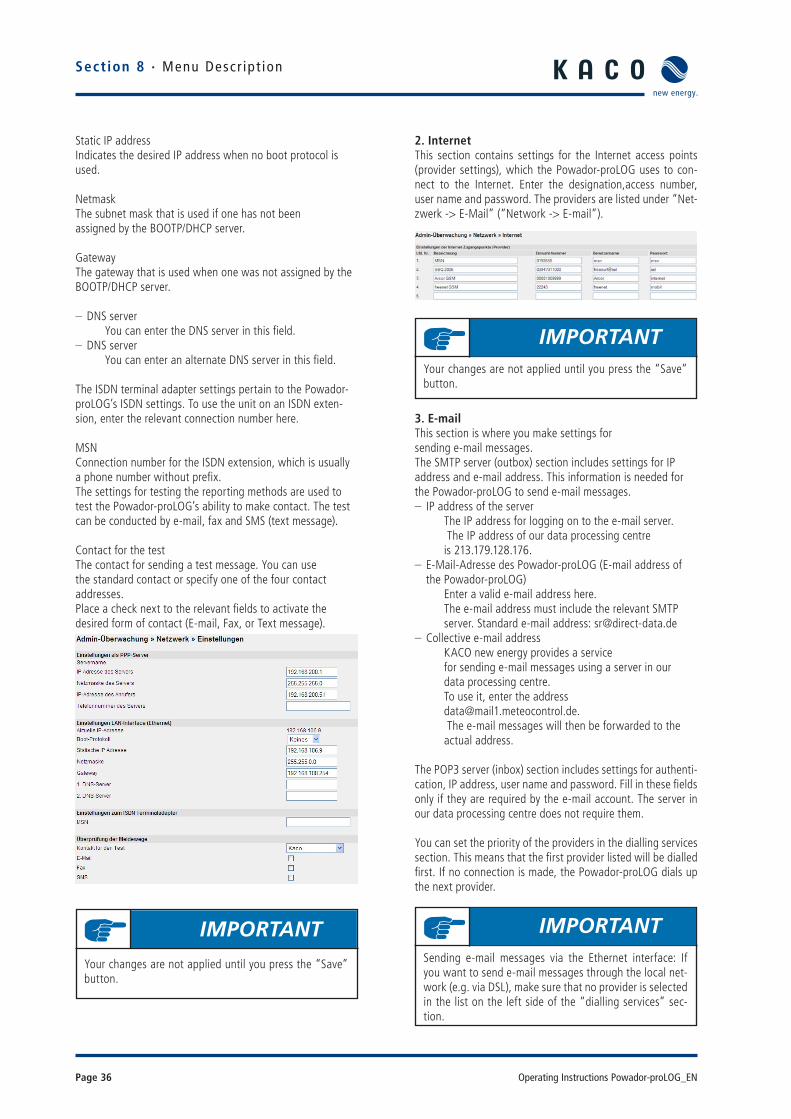
2. InternetThis section contains settings for the Internet access points (provider settings), which the Powador-proLOG uses to con-nect to the Internet. Enter the designation,access number, user name and password. The providers are listed under “Net-zwerk -> E-Mail” (“Network -> E-mail”).
3. E-mailThis section is where you make settings forsending e-mail messages.The SMTP server (outbox) section includes settings for IP address and e-mail address. This information is needed for the Powador-proLOG to send e-mail messages. – IP address of the server
The IP address for logging on to the e-mail server. The IP address of our data processing centre is 213.179.128.176. – E-Mail-Adresse des Powador-proLOG (E-mail address of the Powador-proLOG)
Enter a valid e-mail address here. The e-mail address must include the relevant SMTP server. Standard e-mail address: [email protected] – Collective e-mail address
KACO new energy provides a service for sending e-mail messages using a server in our data processing centre. To use it, enter the address [email protected]. The e-mail messages will then be forwarded to the actual address.
The POP3 server (inbox) section includes settings for authenti-cation, IP address, user name and password. Fill in these fi elds only if they are required by the e-mail account. The server in our data processing centre does not require them.
You can set the priority of the providers in the dialling services section. This means that the fi rst provider listed will be dialled fi rst. If no connection is made, the Powador-proLOG dials up the next provider.
IMPORTANT
Your changes are not applied until you press the “Save” button.
IMPORTANTYour changes are not applied until you press the “Save” button.
IMPORTANTSending e-mail messages via the Ethernet interface: If you want to send e-mail messages through the local net-work (e.g. via DSL), make sure that no provider is selected in the list on the left side of the “dialling services” sec-tion.

Operating Instructions Powador-proLOG_EN Page 37
Sect ion 8 · Menu Descr ipt ion
Synchronisation with database server: Yes/NoWhen you use the “Powador-web” service, you have the option of having all alarm messages sent to both the receiving address and the portal. This means that the fault messages are also accessible in alarm management.
4. SMSThis section contains settings for sending SMS messages (text messages). Enter the numbers for the respective SMS servers here (T-Mobile, Vodafone, E-plus, O2).
Prefi x(es))SMS server prefi x(es), separated by a semi-colon.
SMSC telephone number (analogue))Phone number(s) of the server that is used for sending SMS messages.
SMSC telephone number (ISDN))Phone number(s) of the server that is used for sending SMS messages.
8.5.2 Contact addressesYou can defi ne up to four contacts in the “Contact addresses” section. These contacts are in addition to the standard contact and are alerted in the event of a fault. Fill in the fi elds in the same way you did for the standard contact address.
8.5.3 Switching outputThe settings in this section are used to confi gure the digital output. You can choose between inactive, alarm output and counter output.When confi gured as a counter output for connecting a display, you need to enter a pulse constant. The pulse constant indi-cates how many pulses are emitted by the Powador-proLOG at D0 for one kWh of energy produced.When confi gured as an alarm output for connecting an alarm, you can activate the various alarms in the “Set digital output” section in the lower part of the screen. You can clear the alarms in Admin monitoring -> System messages,Inverters and “Formulas”
IMPORTANTYour changes are not applied until you press the “Save” button.
IMPORTANTYour changes are not applied until you press the “Save” button.
IMPORTANTYour changes are not applied until you press the “Save” button.

Page 38 Operating Instructions Powador-proLOG_EN
Section 8 · Menu Descr ipt ion
8.5.4 System messagesSystem messages only pertain to information or faults in the monitoring system itself. You can make the following settings:
– Status Set this criterion to inactive or active. – Alarm type:
Used for logging on to or registering on the computer that was called. – Alarm destination:
Indicates the contact that is notifi ed when an alarm is triggered. – Alarm counter:
Indicates how often the respective alarm has already occurred. – Current information:
Indicates when the last alarm was triggered. – Reset:
Use the “Reset counter” button to reset the alarm counter.
8.5.5 InvertersThis section contains settings for inverter monitoring. Alarm notifi cation is confi gured by indicating the alarm type (fax, e-mail, SMS) and the alarm destination (three contacts simul-taneously). – Anomaly fi le is too big.
This fi le is used to record the status changes of the inverters. The fi le is too big, because too many status changes were recorded. An alarm message is triggered. – Energy yield deviation:
Only works if the correct DC rated powers of the inverters have been entered. – Inverter does not answer):
This alarm occurs when an inverter does not answer. – Tolerance limit for energy comparison):
This setting pertains to the “Energy yield deviation” alarm type. The characteristic curves of the inverters must remain within this range. The alarm is activated when the upper or lower limit is exceeded. – Time (hour) for checking whether the inverter responded to at least one protocol):
The inverter(s) must have responded to the Powador- proLOG at least once by the set time. Standard value: 13 (13:00). – Number of winter days + 1 before an alarm is sent when a protocol has not been answered):
– Number of consecutive missing protocol answers before an alarm is sent):
– Pacmin [%] for last received protocol for detection of a failure).
8.5.6 FormulasThis section includes settings for defi ning the various criteria for monitoring the system. You can defi ne the following parameters in the Settings sec-tion: – Designation:
Enter the name of the criterion here. – Status:
Set this criterion to inactive or active. – Time:
Analysis on an interval/daily basis – Alarm destination:
Indicates the contact that is notifi ed when an alarm is triggered. – Message type:
Indicates the type of message (e-mail/fax). – Delay:
Indicates how many intervals/days there are to wait before a message is issued when the criterion is in an alarm condition. – Number of triggered alarms:
Indicates the number of alarms that have been registered. – Reset counter:
Use this option to reset the counter (for alarms that have already occurred) to zero.
The formula settings are defi ned usingreverse Polish notation. An example showing how to set a criterion is provided in section 8 (“Confi gurationExample”).

Operating Instructions Powador-proLOG_EN Page 39
Sect ion 8 · Menu Descr ipt ion
8.5.7 Status alarmsThis section is used to evaluate analogue and digital inputs and send alarms accordingly. There are 15 status alarms.You can defi ne the following parameters in the Settings sec-tion:
– Status: Set this criterion to inactive or active. – Designation:
Enter the name of the criterion here. – Alarm destination:
Indicates the contact that is notifi ed when an alarm is triggered. – Message type:
Indicates the type of message (e-mail/fax). – Delay:
Indicates how many seconds there are to wait before a message is issued when the status alarm is in an alarm condition. – Reactivation of the alarm after reset:
Specifi es the time interval after which the alarm is reactivated, in case the measured value for this time interval is below the defi ned limit value. – Number of triggered alarms:
Indicates the number of alarms that have been registered.
The formula setting function includes the following func-tions:
– Analogue: If a specifi ed limit value is exceeded, a message is sent to the contact data defi ned in the settings (for example: measurement for channel 1 >= the limit value of 8.0 V).
– Status: The message is sent if (for example) status channel 1 no longer corresponds to the defi ned low/high fault level.
– Pulse counter: If a specifi ed limit value is exceeded, a message is sent to the contact data defi ned in the settings (for example: counter 1 <= the limit value of 1.0 kW).
8.6 Admin measurement
8.6.1 Analogue channels – Type:
Select the type of sensor to be measured. You can choose between voltage, current and resistance measurement. – Status:
Set this channel to inactive or active. Measured values are logged in data fi les according to status. – Channel/Measured value designation:
Indicates the name of the channel. This designation is used in the online display of measured values. – Code:
Indicates the channel’s code designation. This designation is used in the data fi les. If possible, use one of the codes in the predefi ned list (see section 9: “List of Code Designations”) so that it is easier to synchronise with the Internet database. – Unit:
Specifi es the unit for the measured values. This designation is used in the online display of measured values. – Slope:
The slope is used to convert the measured input voltage to physical values. – Offset:
The offset is entered as a physical value.
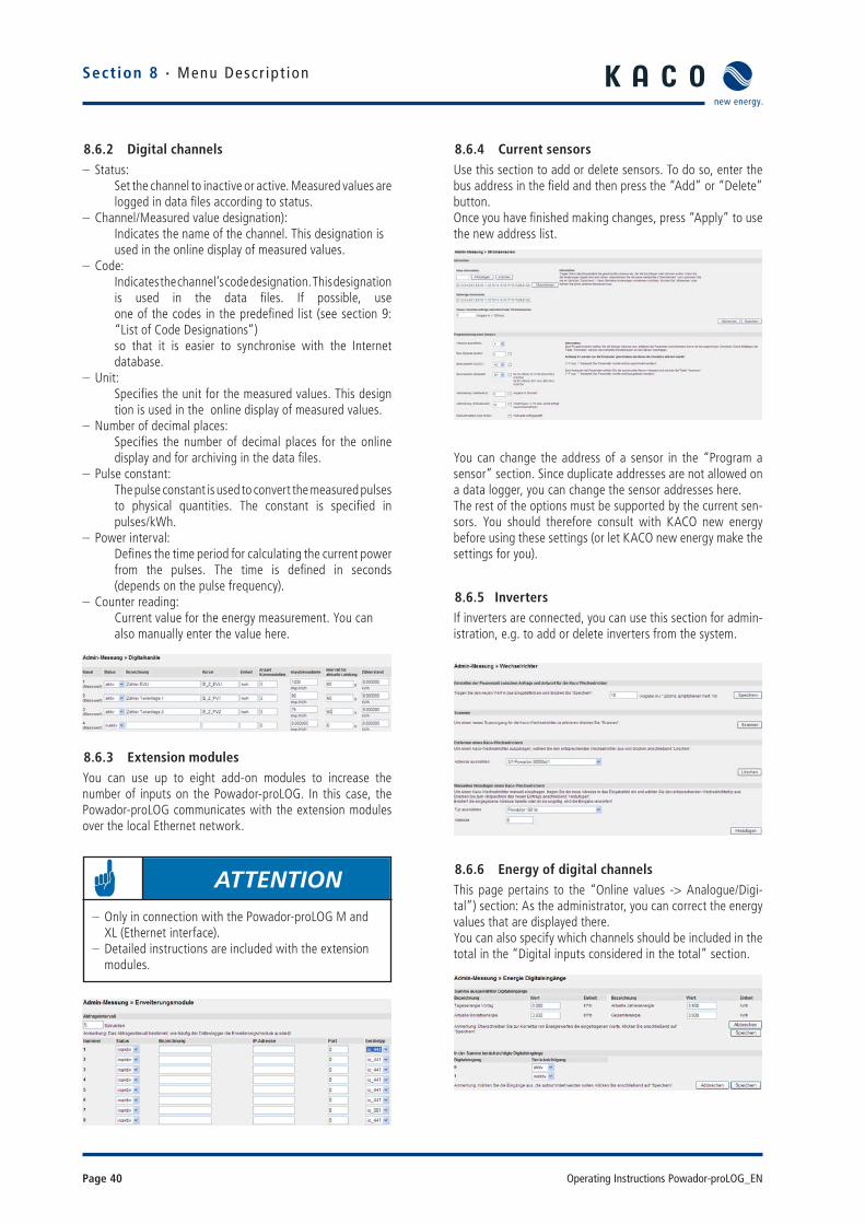
Page 40 Operating Instructions Powador-proLOG_EN
Section 8 · Menu Descr ipt ion
8.6.2 Digital channels – Status:
Set the channel to inactive or active. Measured values are logged in data fi les according to status. – Channel/Measured value designation):
Indicates the name of the channel. This designation is used in the online display of measured values. – Code:
Indicates the channel’s code designation. This designation is used in the data fi les. If possible, use one of the codes in the predefi ned list (see section 9: “List of Code Designations”) so that it is easier to synchronise with the Internet database. – Unit:
Specifi es the unit for the measured values. This design tion is used in the online display of measured values. – Number of decimal places:
Specifi es the number of decimal places for the online display and for archiving in the data fi les. – Pulse constant:
The pulse constant is used to convert the measured pulses to physical quantities. The constant is specifi ed in pulses/kWh. – Power interval:
Defi nes the time period for calculating the current power from the pulses. The time is defi ned in seconds (depends on the pulse frequency). – Counter reading:
Current value for the energy measurement. You can also manually enter the value here.
8.6.3 Extension modules You can use up to eight add-on modules to increase the number of inputs on the Powador-proLOG. In this case, the Powador-proLOG communicates with the extension modules over the local Ethernet network.
8.6.4 Current sensorsUse this section to add or delete sensors. To do so, enter the bus address in the fi eld and then press the “Add” or “Delete” button. Once you have fi nished making changes, press “Apply” to use the new address list.
You can change the address of a sensor in the “Program a sensor” section. Since duplicate addresses are not allowed on a data logger, you can change the sensor addresses here. The rest of the options must be supported by the current sen-sors. You should therefore consult with KACO new energy before using these settings (or let KACO new energy make the settings for you).
8.6.5 InvertersIf inverters are connected, you can use this section for admin-istration, e.g. to add or delete inverters from the system.
8.6.6 Energy of digital channelsThis page pertains to the “Online values -> Analogue/Digi-tal”) section: As the administrator, you can correct the energy values that are displayed there.You can also specify which channels should be included in the total in the “Digital inputs considered in the total” section.
ATTENTION – Only in connection with the Powador-proLOG M and XL (Ethernet interface).
– Detailed instructions are included with the extension modules.

Operating Instructions Powador-proLOG_EN Page 41
Sect ion 8 · Menu Descr ipt ion
8.6.7 Energy of invertersIf inverters are connected, you can use this section to cor-rect the energy values displayed in “Online values -> Inverter overview”.The total will then automatically take all connected inverters into account, so that there is nothing to select here.
8.6.8 Time synchronisationUse this menu item to synchronise the system time on the Powador-proLOG. – No synchronisation:
The system time must be manually set in “Confi guration -> Date/Time”. – Internet synchronisation:
This function is only used in conjunction with Powador-web. – Network synchronisation):
The Powador-proLOG synchronises the time via the gateway of the local network. The gateway must support the time server function.
8.6.9 Active power and idle power control) (XL)The remote-controlled active power and idle power control function can only be used with a Powador-proLOG XL. Select “Admin measurement » Active power and idle power control”) to access all the settings for the remote-controlled function.
a) Confi guration
You can use the “Confi guration” menu item to activate the KACO power control function (active power control) and confi gure the relevant Powador-proLOG as a master orslave.
b) Control
You can use the “Control” menu item to confi gure a wide variety of control methods. Depending on what you select, the page will change accordingly and display the relevant settings. Help is also provided for each of the procedures.
In the lower screen, you can set the values for the KACO power control function, the idle power (as a percentage of the system's rated power) or the cosine phi for control via a radio ripple control receiver.
c) Address list
You can use the “Address list” menu item to enter the IP addresses of the slave units. The master Powador-proLOG XL unit forwards the digital signal of the radio ripple control receiver via Ethernet to all the slaves entered. This means that up to 20 slaves can be managed using just one master.
d) Online values
You can fi nd the current status of the active power and idle power control function under “Online values » Active power and idle power control”
ATTENTION
Only the Powador-proLOG XL unit that has been defi ned as the master is able to forward active power and idle power control commands from the connected radio ripple control receiver to the slave data loggers. All slaves must also be Powador-proLOG XL units.

Page 42 Operating Instructions Powador-proLOG_EN
Section 9 · Conf igurat ion Example
9 Confi guration Example9.1 Analogue channels
9.1.1 Voltage inputThe rule for converting the measured computation value to a physical value is as follows:
Legend:[MW]: current measured value at the channel input in [V].[Measuring scale fi nal value]: for a voltage input of 10 volts.
Example 1:A sensor is to be connected to an analogue channel using a sensor constant of 10 V = 1500 W/m². The measurement range fi nal value of the input is 10 V.The slope is calculated as follows:
If the channel does not show an offset during calibration, you can use 0 for the offset. Assuming the channel has an offset of +15 W/m² (for example) during calibration, set the channel as follows:
Example 2:A PT100 is to be connected to a channel using a voltage trans-former. The voltage transformer supplies an output voltage of 10 V at +100°C and an output voltage of 0 V at –50°C. This results in a physical measurement range fi nal value of 150°C.The slope is calculated as follows:
Since the temperature is to be measured down to -50 °C, the result is an offset of:
Physical full-scale valueChannel full-scale value
[ Physical value ] = [ IV ] × [ Gradient ] + [ Offset ]
= Instantaneous channel value[ IV ]
[ Gradient ] =
= Physical measured value[ Offset ]
Physical measured value = ∑ pulses
Meter constant
9.1.2 Current inputThe rule for converting the measured computation value to a physical value is as follows:
Legend:[MW]: Current measured value at the channel input in [mV].[Measuring scale fi nal value]: for a current input of 20 mA.
9.2 Digital inputsThe following equation is used to convert to a physical quan-tity:
Example: A counter provides 6000 pulses/kWh and is to be connected to a digital input. This counter constant is directly entered as a value in the Pulse constant (pulses/kWh)] fi eld, which means that the online display shows the values as energy [kWh]. To display the current power, you have to enter a value (e.g. 60) in the Interval for current power (s)] fi eld. This means that the pulses are added up over a period of 60 seconds and converted to an average power for this interval period.
9.3 Alarm criterionAn example should help you to achieve simple and effective system monitoring with the unit.
Example:A photovoltaic system is equipped with a solar sensor for measuring irradiance in the module level and a generation counter with pulse output. These quantities are to be used to defi ne limits for reporting a defect in the system by means of a “malfunction call”.
Physical full-scale valueChannel full-scale value
[ Physical value ] = [ IV ] × [ Gradient ] + [ Offset ]
= Instantaneous channel value[ IV ]
[ Gradient ] =
= Physical measured value[ Offset ]
[ Gradient ] = = 1500 W/m²
10150
²/15 mWOffset
[ Gradient ] = = 150 °C
1015
= [ Offset ] -50 °C
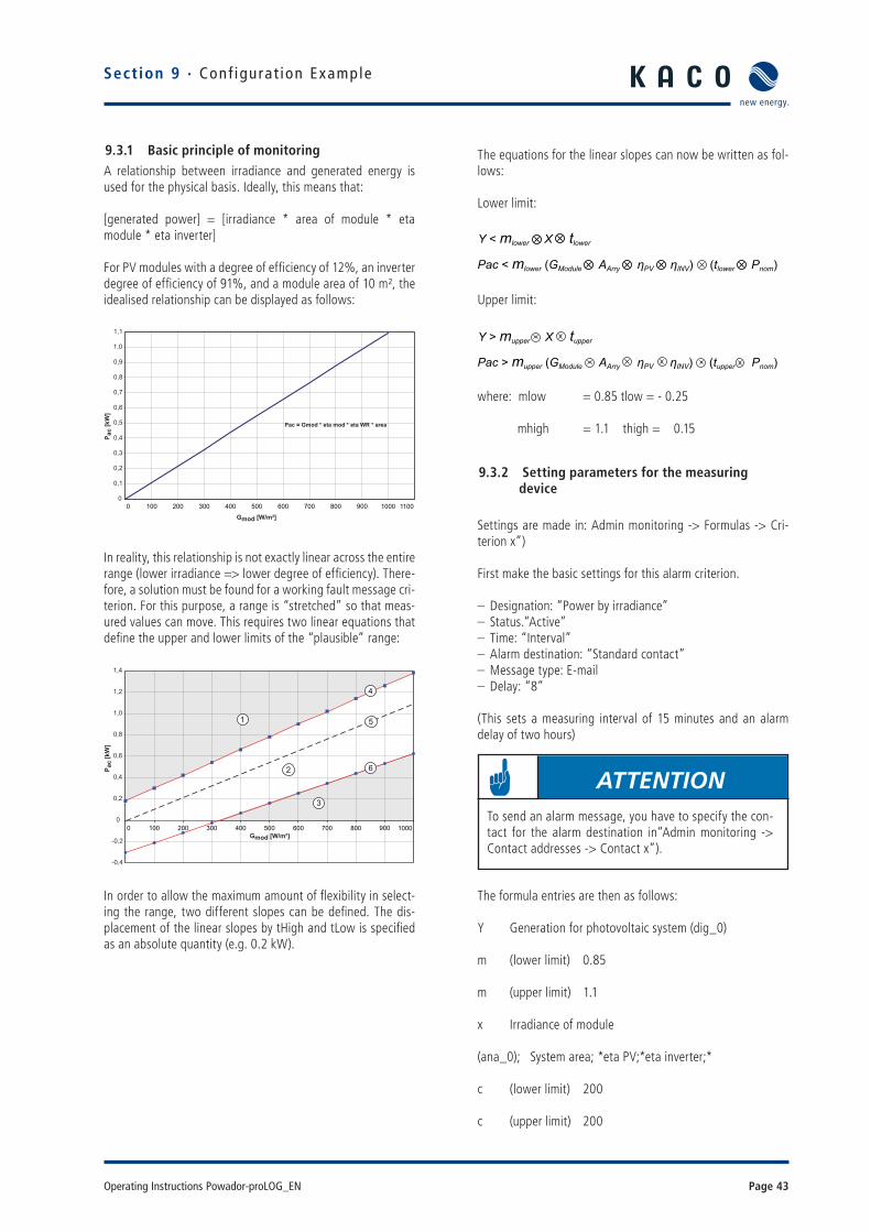
Operating Instructions Powador-proLOG_EN Page 43
9.3.1 Basic principle of monitoringA relationship between irradiance and generated energy is used for the physical basis. Ideally, this means that:
[generated power] = [irradiance * area of module * eta module * eta inverter]
For PV modules with a degree of effi ciency of 12%, an inverter degree of effi ciency of 91%, and a module area of 10 m², the idealised relationship can be displayed as follows:
In reality, this relationship is not exactly linear across the entire range (lower irradiance => lower degree of effi ciency). There-fore, a solution must be found for a working fault message cri-terion. For this purpose, a range is “stretched” so that meas-ured values can move. This requires two linear equations that defi ne the upper and lower limits of the “plausible” range:
In order to allow the maximum amount of fl exibility in select-ing the range, two different slopes can be defi ned. The dis-placement of the linear slopes by tHigh and tLow is specifi ed as an absolute quantity (e.g. 0.2 kW).
0
0,1
0,2
0,3
0,4
0,5
0,6
0,7
0,8
0,9
1,0
1,1
Gmod [W/m²]
P ac
[kW
]
0 100 200 300 400 500 600 700 800 900 1000 1100
Pac = Gmod * eta mod * eta WR * area
-0,4
-0,2
0
0,2
0,4
0,6
0,8
1,0
1,2
1,4
Gmod [W/m²]
P ac
[kW
]
0 100 200 300 400 500 600 700 800 900 1000
6
5
4
3
2
1
The equations for the linear slopes can now be written as fol-lows:
Lower limit:
Upper limit:
where: mlow = 0.85 tlow = - 0.25
mhigh = 1.1 thigh = 0.15
9.3.2 Setting parameters for the measuring device
Settings are made in: Admin monitoring -> Formulas -> Cri-terion x”)
First make the basic settings for this alarm criterion.
– Designation: “Power by irradiance” – Status.“Active” – Time: “Interval” – Alarm destination: “Standard contact” – Message type: E-mail – Delay: “8”
(This sets a measuring interval of 15 minutes and an alarm delay of two hours)
The formula entries are then as follows:
Y Generation for photovoltaic system (dig_0)
m (lower limit) 0.85
m (upper limit) 1.1
x Irradiance of module
(ana_0); System area; *eta PV;*eta inverter;*
c (lower limit) 200
c (upper limit) 200
Section 9 · Conf igurat ion Example
Y < mlower X tlowerPac < mlower (GModule AArry ηPV ηINV) (tlower Pnom)
Y > mupper X tupper Pac > mupper (GModule AArry ηPV ηINV) (tupper Pnom)
ATTENTIONTo send an alarm message, you have to specify the con-tact for the alarm destination in“Admin monitoring -> Contact addresses -> Contact x”).

Page 44 Operating Instructions Powador-proLOG_EN
Section 9 · Conf igurat ion Example
9.4 Programming criteria using the example of an inverter comparisonIn this comparison, the daily energy of inverter 4 is compared with that of inverter 5, and an alarm is triggered if there is an energy yield deviation. Different inverter types can be com-pared with one another. Enter a name for the criterion and activate it in the settings. You can then choose whether the criterion is calculated with each recording interval, or once a day. The code for the daily energy of the respective inverter is entered in the x and y fi elds in the formula settings section (here: EWR_3, EWR_4). The reason the addresses are shifted is because the addresses in the proLOG start with “0” (daily energy from inverter 5 → EWR_4). This value is then divided by the respective installed generator power. This means that values from different inverters can also be compared with one another (here: EWR_3 has 5.6 kW and EWR_4 has 4.8 kW of module power installed). The upper and lower limits are set in the c fi elds. Set the slope for the valid range in the m fi elds. You can usually leave the slope as is.

Operating Instructions Powador-proLOG_EN Page 45
9.5 List of code designations
Measured values Powador-proLOG Unit
Feed-in meter E_Z_EVU kWh
Counter for sub-system 1 E_Z_PV1 kWh
Counter for sub-system 2 E_Z_PV2 kWh
Counter for sub-system 3 E_Z_PV3 kWh
Irradiance in module level 0 G_M0 W/m2
Irradiance in module level, part 1 G_M1 W/m2
Irradiance in module level, part 2 G_M2 W/m2
Irradiance in module level, part 3 G_M3 W/m2
Irradiance in horizontal level G_H0 W/m2
Module temperature T_M0 °C
Module temperature, part 1 T_M1 °C
Module temperature, part 2 T_M2 °C
Ambient temperature T_U0 °C
Ambient temperature 1 T_U1 °C
Collector temperature T_K0 °C
Collector temperature, part 1 T_K1 °C
Direct current I_DC_0 A
Direct current of sub-system 1 I_DC_1 A
Direct current of sub-system 2 I_DC_2 A
Direct current of sub-system 3 I_DC_3 A
DC voltage U_DC_0 V
DC voltage of sub-system 1 U_DC_1 V
DC voltage of sub-system 2 U_DC_2 V
DC voltage of sub-system 3 U_DC_3 V
Alternating current I_AC_0 A
Alternating current of sub-system 1 I_AC_1 A
Alternating current of sub-system 2 I_AC_2 A
Alternating current of sub-system 3 I_AC_3 A
AC voltage U_AC_0 V
AC voltage of sub-system 1 U_AC_1 V
AC voltage of sub-system 2 U_AC_2 V
AC voltage of sub-system 3 U_AC_3 V
Wind speed W_V0 m/s
Wind direction W_R0 °
Humidity F_L0 %
Heat quantity of collector WM_K0 kWh
Heat quantity of heating WM_H0 kWh
Heat quantity of CHP WM_BHKW0 kWh
Section 9 · Conf igurat ion Example

Page 46 Operating Instructions Powador-proLOG_EN
10 UpdateKACO new energy cannot assume any liability or repair costs for damage resulting from a failure to observe these instruc-tions. Please do not make changes to any directories or fi les other than the ones described.
10.1 Update with card reader
10.1.1 General informationA Compact Flash (CF) card is built into the Powador-proLOG. The entire operating system for the Powador-proLOG and all the system fi les are stored on this card. You will fi nd the card slot on the right-hand side of the housing.
10.1.2 InstructionsTo perform the update, you will need a Powador-proLOG, a card reader for CF cards, a PC or laptop and the new software (which you can obtain via the monitoring service).
Section 10 · Update
DANGER
Before starting the update, make sure to disconnect the power plug for the data logger. The Powador-proLOG must be switched off when removing the card from the data logger.
NOTE
After the update, the unit will need to be reconfi gured using the installation wizard.
ACTION
– Remove the protective cover from the card slot and take out the CF card.
– Insert the CF card into the reader and connect the reader to the PC/laptop.
– Start Windows Explorer and open the card reader drive. – Create a backup copy by saving the CF card fi les to a folder of your choice on the PC/laptop.
ACTION
– Format the CF card by right-clicking on the drive. Unzip the new software that you obtained from the monito-ring service in the form of a ZIP fi le.

Operating Instructions Powador-proLOG_EN Page 47
ACTION
– Copy the unzipped fi les to the CF card. It is recommen-ded that you save the “data” folder from your backup copy onto the CF card. This will ensure that you have all the daily fi les on the Powador-proLOG.
– Open the fi le “anlage.ini” (which you can fi nd in path “ISTCONF\ANLAGE”) and enter the serial number of your data logger.
ACTION
– Insert the CF card again (with the KACO new energy logo at the top) and switch on the unit. The start pro-cess is complete when the status LED starts to fl ash. The new software is installed.
– Now run the installation wizard in order to reconfi gure the data logger.
Section 10 · Update
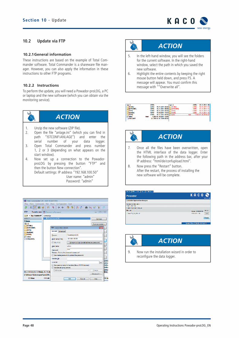
Page 48 Operating Instructions Powador-proLOG_EN
10.2 Update via FTP
10.2.1 General informationThese instructions are based on the example of Total Com-mander software. Total Commander is a shareware fi le man-ager. However, you can also apply the information in these instructions to other FTP programs.
10.2.2 InstructionsTo perform the update, you will need a Powador-proLOG, a PC or laptop and the new software (which you can obtain via the monitoring service).
ACTION
1. Unzip the new software (ZIP fi le).2. Open the fi le “anlage.ini” (which you can fi nd in path “ISTCONF\ANLAGE”) and enter the serial number of your data logger.3. Open Total Commander and press number 1, 2 or 3 (depending on what appears on the start window). 4. Now set up a connection to the Powador- proLOG by pressing the button “FTP” and then the button New connection”. Default settings: IP address “192.168.100.50” User name: “admin” Password: “admin”
ACTION5. In the left-hand window, you will see the folders for the current software. In the right-hand window, select the path in which you saved the new software.6. Highlight the entire contents by keeping the right mouse button held down, and press F5. A mes sage will appear. You must confi rm this mes sage with ““Overwrite all”.
ACTION
7. Once all the fi les have been overwritten, open the HTML interface of the data logger. Enter the following path in the address bar, after your IP address: “html/de/confupload.html”. 8. Now press the “Restart” button. After the restart, the process of installing the new software will be complete.
ACTION
9. Now run the installation wizard in order to reconfi gure the data logger.
Section 10 · Update

3100
1085
-02-12
0222
Carl-Zeiss-Straße 1 · 74172 Neckarsulm · Germany · Phone +49 7132 3818-0 · Fax +49 7132 3818-703 · [email protected] · www.kaco-newenergy.de
The
text
and
fi gu
res
refl e
ct t
he c
urre
nt t
echn
ical
sta
te a
t th
e tim
e of
prin
ting.
Sub
ject
to
tech
nica
l cha
nges
. Err
ors
and
omis
sion
s ex
cept
ed.