Embed Size (px)
Citation preview

ProMaster PM200BT & PM400BTSwimming Pool Pump
Installation and Operating Instructions
50/60Hz
Please refer to the Davey website in your region as per back page of this document for any product information updates.
ProMaster®
Please pass these instructions on to the operator of this equipment.
PM200BTPM400BT

2
Congratulations on your purchase of a high quality, ProMaster PM200BT, or PM400BT pump. All components have been designed and manufactured to give trouble free, reliable operation.
Table of Contents:1. INSTALLATION OF THE DAVEY PROMASTER VARIABLE SPEED PUMP .............................................3 Power connection .......................................................................................................................................3 Pipe connection ..........................................................................................................................................42. TYPICAL INSTALLATION DIAGRAM .........................................................................................................53. PERFORMANCE SPECIFICATIONS .........................................................................................................5 PM200BT Hydraulic Performance ..............................................................................................................5 PM200BT Electrical Specifications .............................................................................................................6 PM400BT Hydraulic Performance ..............................................................................................................6 PM400BT Electrical Specifications .............................................................................................................64. OWNERS MANUAL ....................................................................................................................................7 Saving energy with your ProMaster ............................................................................................................7 Pre-start up checklist ..................................................................................................................................7 Low energy operation .................................................................................................................................8 Guidelines for recommended pump operating hours ..................................................................................8 Emptying the strainer basket ......................................................................................................................9 Routine maintenance ..................................................................................................................................95. FEATURES & FUNCTIONALITY ..............................................................................................................10 Multi-Coloured LED indicator light ............................................................................................................10 Backwash Speed Cycling Technology ......................................................................................................10 Full variable frequency drive with user friendly selectable speed dial ......................................................10 Large 4.5 litre lint pot ................................................................................................................................10 Patented water-cooled design for smooth and super quiet operation ......................................................10 PM400BT constant flow/speed compensation ..........................................................................................10 PM400BT weatherproof RJ45 Communication Port (see section 7 for connection details) .....................106. BLUETOOTH FUNCTIONALITY ..............................................................................................................11 Bluetooth App Set Up ...............................................................................................................................11 Pairing a device to the pump ....................................................................................................................11 External Timer / Chlorinator ......................................................................................................................11 Schedule mode .........................................................................................................................................11 Setting a schedule ....................................................................................................................................12 Settings .....................................................................................................................................................12 Priming speed / Max speed ......................................................................................................................12 Backwash..................................................................................................................................................13 External time present ................................................................................................................................13 Disconnect function ..................................................................................................................................13 Factory reset .............................................................................................................................................13 Pump fault finding .....................................................................................................................................137. ADVANCED SETUP OF PM400BT ..........................................................................................................14 External AUX connections overview .........................................................................................................14 Digital control inputs .................................................................................................................................15 Interfacing equipment to the ProMaster PM400BT ...................................................................................15 Analogue control inputs ............................................................................................................................168. TECHNICAL SPECIFICATIONS ...............................................................................................................169. USING YOUR PROMASTER WITH A SALT WATER CHLORINATOR ....................................................1710. OPERATING YOUR SUCTION POOL CLEANER ....................................................................................1711. TROUBLE SHOOTING .............................................................................................................................1812. REMOVAL OF THE PROMASTER FROM PIPEWORK ...........................................................................1813. WATER QUALITY .....................................................................................................................................1814. DAVEY WARRANTY .................................................................................................................................20

3
1. INSTALLATION OF THE PROMASTERThe ProMaster should be located as close to the water as practicable and mounted on a firm base in a well drained position, high enough to prevent any flooding. It is the installer/owner’s responsibility to locate the pump such that the nameplate can be easily read and the ProMaster can be readily accessed for service. It is recommended that the ProMaster is protected from the weather. Enclosures should be ventilated to prevent condensation build-up.
Failure to follow these instructions and comply with all applicable codes may cause serious bodily injury and/or property damage. This pump requires professional expertise for installation and maintenance. The installation of this product should be carried out by a person knowledgeable in swimming pool plumbing requirements and who follows the installation instructions provided in this manual.
Power connection
IMPORTANT INFORMATION Your ProMaster is double insulated to water circuit. If equipotential bonding structure is required, then an Equipotential Bonding Point is provided. (Please refer to your local statutes and/or regulations for AS/NZ 3000 equivalent wiring standards).CAUTION! In the interest of safety, we advise that all brands and types of pool pumps must be installed in accordance with AS/NZS 3000, known as the national wiring rules, or equivalent local standards. All electrical installations must be carried out by a qualified electrician. Davey recommends that all installations are fitted with earth leakage, or residual current protection devices. Rated residual operating current not exceeding 30mA.WARNING! Ensure that an electrical isolation switch is located with easy access so that the pump can be switched off in an emergency.
F NFC C 15-100 GB BS7671:1992
D DIN VDE 0100-702 EW EVHS-HD 384-7-702
A OVE 8001-4-702 H MSZ 2364-702:1994/MSZ 10-533 1/1990
E UNE 20460-7-702 1993, REBT ITC-BT-31 2002 M MSA HD 384-7-702.S2
IRL IS HD 384-7-702 PL PN-IEC 60364-7-702: 1999
I CEI 64-8/7 CZ CSN 33 2000 7-702
LUX 384-7.702 S2 SK STN 33 2000-7-702
NL NEN 1010-7.702 SLO SIST HD 384-7-702.S2
The ProMaster is suitable for connection to a nominal 220 – 240 volt 50/60Hz power supply and is equipped with a flex cord. If a power outlet is not available within 3 metres of the pump, a 3-pin power point in a safe, dry place may need to be provided by an electrician. Extension cords are unsafe around pools and should be avoided. If the supply cord of the ProMaster is damaged it must be replaced by Davey, or an approved agent with genuine Davey spares.
The ProMaster incorporates motor overload detection designed to protect the motor from overheating. If the motor gets too hot during operation, its operating speed will reduce to bring it within an acceptable operating temperature and then will speed up to the originally set speed.
To reset the motor, switch the power off for 30 seconds, and then return the power from the mains switch.

4
Pipe connectionBarrel unions are provided for connecting to the piping from the pool. The pumps are designed to accept 40/50mm PVC fittings.
IMPORTANT INFORMATION If the ProMaster and filter are located below pool water level, it is necessary to fit isolating valves in the pipe between the pump and skimmer box and in return pipe from the filter to the pool. When plumbing the discharge pipe, ensure that the pipework does not interfere with the pumps speed dial. Barrel unions need to be hand tightened. No sealant, glues or silicones are required.The fittings on the ProMaster are constructed of ABS. Some PVC jointing compounds are incompatible with ABS. Check compound suitability before use.
The use of any pipe smaller than those specified above is not recommended. Suction piping should be free from all air leaks and any humps and hollows which cause suction difficulties. To achieve best efficiency, the ProMaster should be installed such that turbulent water is limited as much as possible. As shown in figure 1.1, do not install a 90° elbow closer that 250mm from the inlet barrel union. Isolation valves used where equipment is located below pool water level, should also be installed no closer than 250mm from inlet barrel union. This will assist laminar flow.
250mm
ELBOW
Figure 1.1
Figure 1.2152mm
MINIMUM
76mmMINIMUM
Suction line40/50mm
Return toPool40/50mm
Suction line40/50mm
Return toPool40/50mm
The discharge piping from the ProMaster outlet should be connected to the inlet connection on the swimming pool filter (usually at the filter control valve). As shown in figure 1.2, ensure adequate clearance above the pump to not interfere with the ProMaster speed dial. Use a check valve in the discharge line when using this pump for any application where there is significant height to the plumbing after the pump.
250mm
ELBOW
Figure 1.1
Figure 1.2152mm
MINIMUM
76mmMINIMUM
Suction line40/50mm
Return toPool40/50mm
Suction line40/50mm
Return toPool40/50mm
Be sure to install check valves when plumbing with another pump. This helps prevent reverse rotation of the impeller and motor.
WARNING! Pump suction is hazardous and can trap and drown, or disembowel bathers. Do not block suction. Do not operate swimming pools, spas, or spa baths if a suction cover is broken, missing or loose. Two suction covers, or inlets must be provided into every pump to avoid suction entrapment.

5
2. TYPICAL INSTALLATION DIAGRAM
Pool pump Media Filter
3. PERFORMANCE SPECIFICATIONS PM200BT hydraulic performance
0
5
10
15
20
25
0 50 100 150 200 250 300 350 400
To
tal H
ea
d (
m )
ProMaster - PM200SV Performance
Dial position No. 10
Dial position No. 9
Dial position No. 8
Dial position No. 7
Dial position No. 6
Dial position No. 5
Dial position No. 4
Dial position No. 3
Dial position No. 2
Dial position No. 1
Flow ( lpm )
Flow ( m3/h )
00 3 6 9 12 15 18 21 24

6
PM200BT electrical specifications
FlowSetting
Best efficiency point Maximum
Flow Head Input power (P1)
Output power (P2) Flow Head Input power
(P1)Output power
(P2)L/min m³/h m hp W hp W L/min m³/h m hp W hp W
Dial 1 85 5.1 3 0.16 123 0.11 86 155 9.3 4 0.17 128 0.12 90 Dial 2 100 6.0 4 0.26 193 0.18 135 187 11.2 6 0.28 207 0.19 145 Dial 3 125 7.5 5 0.38 283 0.26 198 217 13.0 7 0.39 293 0.27 205 Dial 4 143 8.6 6 0.51 383 0.36 268 246 14.8 10 0.53 398 0.37 279 Dial 5 155 9.3 8 0.66 495 0.46 347 272 16.3 12 0.70 524 0.49 367 Dial 6 160 9.6 10 0.82 612 0.57 428 297 17.8 14 0.87 655 0.61 459 Dial 7 183 11.0 11 1.02 766 0.71 536 322 19.3 16 1.08 807 0.75 565 Dial 8 195 11.7 12 1.17 880 0.82 616 339 20.3 17 1.25 936 0.87 655 Dial 9 207 12.4 13 1.36 1,017 0.95 712 358 21.5 19 1.44 1,078 1.01 755 Dial 10 210 12.6 14 1.45 1,090 1.02 763 363 21.8 20 1.48 1,111 1.04 778
PM400BT hydraulic performance
0
5
10
15
20
25
0 50 100 150 200 250 300 350 400 450
Tota
l H
ead (
m )
Dial position No. 10
Dial position No. 9
Dial position No. 8
Dial position No. 7
Dial position No. 6
Dial position No. 5
Dial position No. 4
Dial position No. 3
Dial position No. 2
Dial position No. 1
Flow ( lpm )
Flow ( m3/h )
00 3 6 9 12 15 18 21 24 27
PM400BT electrical specifications
FlowSetting
Best efficiency point Maximum
Flow Head Input power (P1)
Output power (P2) Flow Head Input power
(P1)Output power
(P2)L/min m³/h m hp W hp W L/min m³/h m hp W hp W
Dial 1 98 5.9 2 0.16 117 0.11 82 160 9.6 3 0.17 126 0.12 88 Dial 2 112 6.7 4 0.26 192 0.18 134 197 11.8 5 0.28 210 0.20 147 Dial 3 140 8.4 5 0.42 316 0.29 221 240 14.4 8 0.46 347 0.32 243 Dial 4 165 9.9 7 0.62 468 0.44 328 282 16.9 10 0.70 522 0.49 366 Dial 5 190 11.4 9 0.88 660 0.62 462 322 19.3 13 0.97 728 0.68 509 Dial 6 200 12.0 11 1.09 817 0.76 572 349 21.0 15 1.22 912 0.85 638 Dial 7 225 13.5 13 1.44 1,080 1.01 756 388 23.3 19 1.61 1,211 1.13 848 Dial 8 240 14.4 15 1.77 1,330 1.24 931 414 24.9 22 1.97 1,478 1.38 1,034 Dial 9 250 15.0 16 1.99 1,495 1.40 1,047 420 25.2 24 2.18 1,636 1.53 1,145 Dial 10 260 15.6 16 2.16 1,620 1.51 1,134 420 25.2 26 2.19 1,639 1.53 1,147

7
4. OWNERS MANUAL
This ProMaster is Bluetooth enabled, so you will be able to set and control the pump functions from your smart device. Bluetooth is a wireless communication protocol that enables communication between devices. This function is supported by any device that can download an app from IOS or Android App Store.
Read these instructions in their entirety before switching on this pump. If you are uncertain as to any of these installation and operating instructions, please contact Davey as listed on the back of this document.
Every ProMaster is thoroughly water tested against a number of flow, pressure, voltage, current and mechanical performance parameters. Davey’s advanced pump manufacturing technology provides reliable and efficient pumping performance that lasts and lasts.
Saving energy with your ProMasterThe Davey variable speed pump is a super-efficient pump utilising a very clever, state of the art infinitely variable AC motor that provides lower levels of noise, lower operating costs and lower greenhouse emissions than traditional pool pumps.
Due to its ability to run at lower speeds than conventional pumps, your pump will also experience less mechanical wear and tear due to less stress on the internal mechanical components. To achieve energy efficient pumping is easy. Simply run the filtration pump at a lower speed but run it for longer than a conventional fixed speed pump to “turn over” your pool water for adequate filtration and sanitisation. The result is lower energy use and up to 70% lower operational costs.
The ProMaster has adjustable speed settings, so you can vary the speed you circulate your pool or spa water at. Speeds can be adjusted to power a suction pool cleaner, in-floor cleaning system & pool heaters. A backwash setting on the pump can be selected to backwash a media filter.
What to expect with the ProMaster (energy efficient operation) on your pool:
• If your ProMaster pump is replacing a traditional AC motor pump, you may will need to run it longer than your old fixed speed pump. This is NORMAL and you will save energy when using lower speed settings.
• You may also notice that the pressure gauge on your filter is indicating a much lower pressure than you are used to. This is also NORMAL. The lower system pressure is simply a result of the lower speed and flow rate produced by the pump.
• While running at the lower speed settings you will also notice a significant reduction in pump noise. This is a major benefit for you as it allows you to run your ProMaster during off peak electricity tariffs, which will also assist in the reduction of your operating costs. Plus, you will also have much happier neighbours.
Many pool products rely on minimum flow rates for best operation and/or efficiency. If you are using low flow settings on the ProMaster (e.g. speed 1 to 4) Davey recommends that you check the compatibility of the speed or minimum flow rate required to run specific pool equipment such as:
• Suction pool cleaners;• Ozone generators;• Heating systems;• Salt water chlorinator cells;• In-floor pool cleaning systems.
Pre-start up checklist
• Speed setting chosen is a compatible setting with other pool equipment;• The pump is installed in a safe and dry environment;• The pump enclosure has adequate drainage in the event of leakage;• Any transport plugs are removed;• The pipe-work is correctly sealed and supported;• The pump is primed correctly;• The power supply is correctly connected;• All steps have been taken for safe operation;• The filter has been plumbed with 40/50mm pipe;• The (app) schedule settings correspond with any other times in the system.

Low energy operationYour ProMaster PM200BT has speed settings from 1,500 - 3,600rpm. The ProMaster PM400BT has speed settings from 1,050 - 3,100rpm. Speed 1 being the slowest and speed 10 being the fastest.
• Speed 1 provides the lowest speed and therefore the greatest energy efficiency and savings.
Operation Recommended Speed SettingBackwashing your media filter Backwash SpeedPool Filtration Speed 1 to 4Suction pool cleaner operation Speed 5 to 8Manually cleaning your pool
Speed 9 to 10
Water Feature operation
Spa Jet operation
In-floor cleaning systems
Solar pool heating
Guidelines for recommended pump operating hoursTypical residential pool turnover rate shall be a single turnover of the full volume of the pool water, within the daily period that the pump would normally be operating. The table below provides a guide only to the running times of your pump while in filtration mode in order to achieve the minimum turnover rate:
ProMaster PM200BT
Pool size(Litres)
Speed Setting (hours)Speed 1 Speed 5 Speed 10
20,000 3.3 1.7 1.1
30,000 5.0 2.5 1.7
40,000 6.7 3.3 2.2
50,000 8.3 4.2 2.8
60,000 10.0 5.0 3.3
80,000 13.3 6.7 4.4
100,000 16.7 8.3 5.6
ProMaster PM400BT
Pool size(Litres)
Speed Setting (hours)Speed 1 Speed 5 Speed 10
20,000 2.4 1.3 0.9
30,000 3.7 2.0 1.4
40,000 4.9 2.7 1.9
50,000 6.1 3.3 2.3
60,000 7.4 4.0 2.8
80,000 9.8 5.3 3.8
100,000 12.3 6.7 4.7
8
9
In accordance with AS/NZS 60335.1 we are obliged to inform you that this appliance appliance is not intended for use by persons (including children) with reduced physical, sensory or mental capabilities, or lack of experience and knowledge, unless they have been given supervision or instruction concerning use of the appliance by a person responsible for their safety. Children should be supervised to ensure they do not play with the appliance.
Emptying the strainer basketThe strainer basket should be inspected frequently through the transparent lid and emptied when a build-up of rubbish is evident. The directions below should be followed.
• Switch off pump;
• Unscrew the strainer basket lid anti-clockwise and remove;
• Remove the strainer basket by lifting upwards from its housing;
• Empty the trapped refuse from the basket. Hose out with water if necessary.
NOTE: NEVER knock the plastic basket on a hard surface as it will cause damage.
• Check the strainer basket for cracks, replace the strainer basket in the pump if damaged;
• Replace the lid and ensure that it seals on the large rubber o-ring. Firm hand tightness only is required. The o-ring & thread can be lubricated with Hydra Slip or equivalent products.
Failure to undertake regular maintenance may cause damage not covered by warranty.
Routine maintenanceTo maximise the life of the ProMaster, and for personal safety use this checklist once a week. Ensure pump is off before starting:
• Make sure that any pressure gauges are in working condition and the operating pressure is within limits as specified on the product;
• Make sure that each suction inlet and main drain has a cover that is securely attached and in safe working condition;
• Make sure that all skimmer covers are securely attached and in safe working condition. These should be replaced every 3 to 4 years;
• Remove any obstructions or debris from the main drain cover;
• Ensure the skimmer and pump baskets are free of leaves and debris at least once a week;
• Remove obstructions and combustibles from around the pump motor;
• Make sure all wiring connections are clean and that all wiring and electrical equipment is in good condition. Damaged wiring must be repaired or replaced by a qualified electrician as soon as damage is discovered;
• Check water balance and sanitizer levels at your local pool shop.
10
5. FEATURES & FUNCTIONALITYThe ProMaster has several operational features. The following explain each of these.
Multi-coloured LED indicator lightUsed for identifying required settings for programming time for full speed (Boost) cycling and warnings:
• Solid green = Normal dial operation
• Slow flashing green = In backwash mode
• Fast Flashing green = AUX external control
• Solid White = Time to Backwash
• Fast Flashing White = Fault detected - reset pump
• Slow Flashing blue = Operated by Bluetooth
• Solid blue = Bluetooth mode
Backwash speed cycling technologyWhen in backwash mode the ProMaster will cycle between a low and high speed to help agitate the filter media for a more effective clean. This reduces wasted water and chemicals during the backwash cycling process.
Full variable frequency drive with user friendly selectable speed dial• Provides for easy selection of desired filtration speed
• No complicated digital push button controls
Large 4.5 litre lint pot• Provides for longer intervals between cleaning
Patented water-cooled design for smooth and super quiet operationThe ProMaster has a water-cooled membrane and jacket around the motor which helps to keep the pump cool during operation. Waste heat off the motor is transferred into the pool water, helping to reduce pool heating energy costs.
PM400BT constant flow/speed compensationAs the pool filter becomes dirty, pressure builds up. With a typical pool pump, this would naturally slow the flow coming through the system. The ProMaster has the intelligence to automatically detect the resistance applied by a filter and slowly compensate the reduction flow, by increasing the speed of the motor. The result is the flow remains constant between filter cleans.
When the ProMaster detects that the speed increase indicates time to backwash your filter, the LED indicator will show a solid white display (see item above).
PM400BT weatherproof RJ45 communication port (see section 7 for connection details)
• For communication and connecting to external pool control systems
• For receiving a signal from a heat pump, or gas heater to ramp the ProMaster speed to full during the heating process
• Service diagnostics and software updates (For Davey use only)

11
6. BLUETOOTH FUNCTIONALITYBluetooth app set up• Open the “App Store” app that is available on your device.
• Search “Davey Pool Pump”
• Install the app on your device
The app can be installed on to as many devices as desired, however, only one device can control the pump at any given time. The language and time of the app is the same as your device setting. The measuring units are automatically defaulted to your device’s region units, however, you can choose between Litres, Gallons or m3/hr.
Pairing a device to the pump• Open app on your smart device.
• Turn dial on the pump from “off” to “Bluetooth”, you will see the LED flash white for a second.
• On your device, press the connect button.
• When setting up for the first time ONLY, select “YES” to allowing location.
• Please note that the first time the devices are paired, there is a 2-minute time limit to do so before the procedure will have to be repeated.
External timer / chlorinatorA pop-up will appear asking if you are using an external timer, or chlorinator to control the ProMaster. Please select “yes”, “no”. This is a safety function that helps ensure the chlorinator only runs when the pump is working.
Note: App screenshots are for demonstration purposes only. Actual screens may vary.
Manual, or scheduled modeTwo modes are available depending on whether you wish to manually operate the ProMaster, or alternatively you can create a schedule of operation.
Manual mode• If in schedule mode, press “switch to manual mode”
• The app will now be in manual mode and you can manually adjust the speed by pressing the (+/ -) buttons.
• In manual mode, the ProMaster will run at the set speed, even if the phone is not in range.
• Anytime the dial is switched to the Bluetooth position, it will run at the previous set speed after the priming cycle.
Schedule mode• There are two options (set a daily cycle, or a weekly cycle) by
pressing the desired box.
• This option allows you to either create a standard “daily schedule” which will consistently operate the set levels every day;
This pop-up will show
To switch between manual or schedule mode you can press this button.
ProMaster BT

12
There are two options (set a daily cycle or a weekly cycle) by pressing the desired box. This option allows you to either create a standard “daily schedule” which will consistently operate the set levels every day
• The “weekly cycle” option can be set for the entire week, giving you the ability to alter daily pump cycles depending on the weather, bather load etc.
Setting a schedule• Select the box which relates to the time that you require the
pump to operate;
• Select the speed setting you would like the pump to run at any time. Note: Settings of the pump (1-10) refers to slowest to fastest operating speed of the pump;
• Once you are happy with your schedule, select “Save”. Communications between the device and the pump can take up to 20 seconds depending on the schedule selected;
• The row at the bottom of the screen indicates a summary of where the schedule is by day and by hour. This summary screen can easily be altered by swiping up or down the columns above;
• Note: If using a chlorinator, you must ensure that the “on” times on the pump correspond to the “on” times on the chlorinator. The pump will remain in the last used mode, whether that be manual mode or schedule mode.
SettingsTo alter setup settings, click on the settings icon:
This will display the following screens (scroll down screen for full information).
Priming speed / max speedEach time your pump starts it will go through 2 minutes of priming to ensure there is water in the system. You can adjust the speed in which it does this between 5 & 10. The speed you set will limit the maximum speed the pump will run in manual or schedule mode.
Select if you would like the daily cycle or the weekly cycle.
Select to edit the schedule settings
ProMaster BT
13
BackwashCan be set as a single speed or alternatively set two speeds and the pump speed will “pulse” between the two settings. Minimum speed can be set between 1-10, maximum speed can only be set between 5-10.
External time presentSwipe this on or off, depending on whether you are using an external timer/chlorinator.
Disconnect functionThe “disconnect from pump” function can be used to:
• Allow another device to control the pump;
• Disconnect so that you will not automatically connect to the pump;
• Please note that the Bluetooth connection will automatically disconnect after a minute of no communication.
Factory resetThis will reset the pump back to factory configurations and allows you to start the setup process again.
• Select “reset pump”;
• Turn dial to “off” position, then turn dial to “Bluetooth”;
• You can then re-pair with your phone. This procedure is in place so that the pump cannot accidentally be reset.
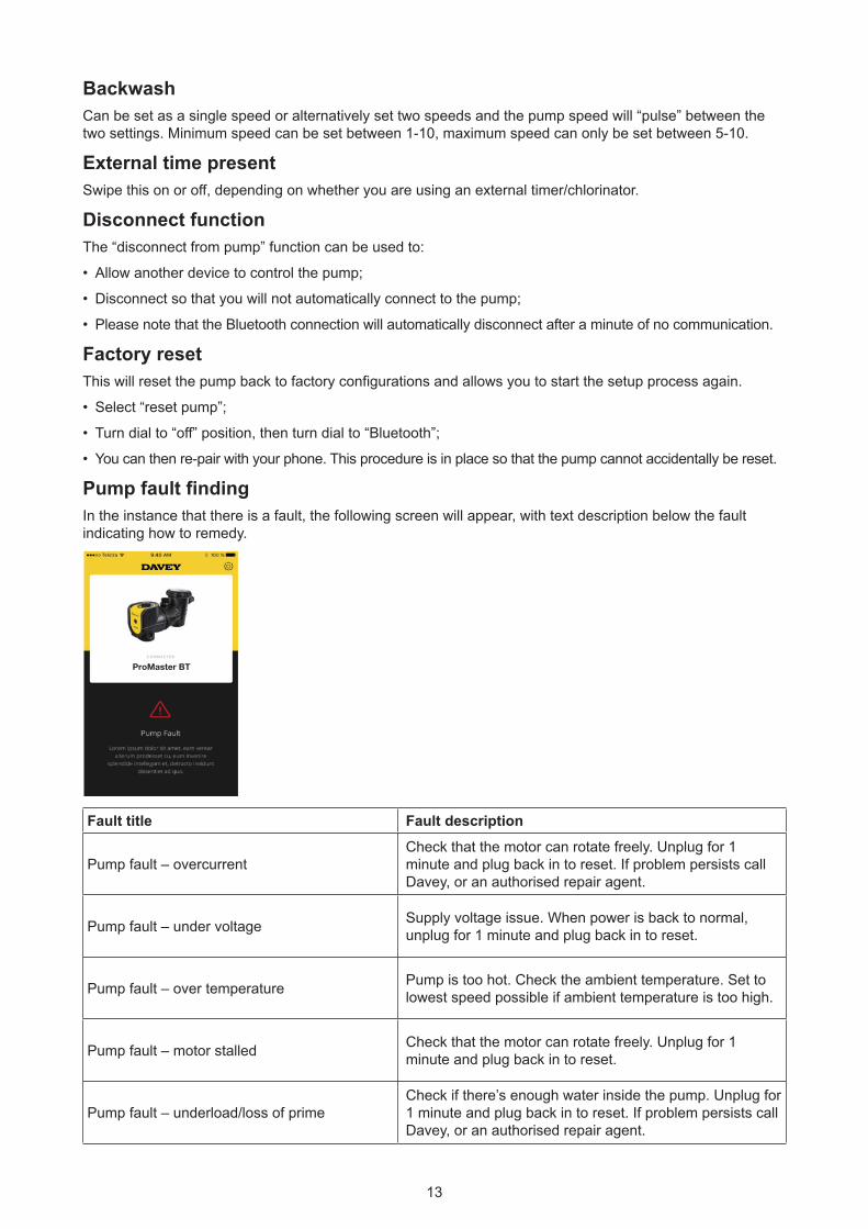
Pump fault findingIn the instance that there is a fault, the following screen will appear, with text description below the fault indicating how to remedy.
ProMaster BT
Fault title Fault description
Pump fault – overcurrent Check that the motor can rotate freely. Unplug for 1 minute and plug back in to reset. If problem persists call Davey, or an authorised repair agent.
Pump fault – under voltage Supply voltage issue. When power is back to normal, unplug for 1 minute and plug back in to reset.
Pump fault – over temperature Pump is too hot. Check the ambient temperature. Set to lowest speed possible if ambient temperature is too high.
Pump fault – motor stalled Check that the motor can rotate freely. Unplug for 1 minute and plug back in to reset.
Pump fault – underload/loss of primeCheck if there’s enough water inside the pump. Unplug for 1 minute and plug back in to reset. If problem persists call Davey, or an authorised repair agent.

14
Pump fault – motor over temperature; or
Pump fault – over voltage; or
Pump fault – earth fault; or
Pump fault – system fault; or
Pump fault – output phase fault; or
Pump fault – power overload; or
Pump fault – EEPROM checksum; or
Pump fault – watchdog error; or
Pump fault – back EFM protection; or
Pump fault – thermistor fault; or
Pump fault – safe torque off; or
Pump fault – internal bus communication; or
Pump fault – application error; or
Pump fault – IGBT temperature high; or
Pump fault – 4mA analogue input fault; or
Pump fault – external fault; or
Pump fault – keypad communication error; or
Pump fault – fieldbus communication error; or
Pump fault – fieldbus interface error.
Unplug for 1 minute and plug back in to reset. If problem persists call Davey, or an authorised repair agent.
7. ADVANCED SETUP OF PM400BTExternal AUX connections overviewYour ProMaster PM400BT has an RJ45 style waterproof socket to allow for external control of motor speed and other functionality. A standard RJ45 network cable (without boot) can be used.
Figure 7.1: RJ45 Plug installed in housing (from rear)
It is recommended to keep the cable length between the pump and external pool controller or heater as short as possible. There are two major pin configurations as shown below:
RJ45 PINOUT
Figure 7.2: RJ45 pin connections

15
Pin Function T-568A T-568B1 RS485 +ve Green/white Orange/white
2 RS485 -ve Green Orange
3 Digital input 3 Orange/white Green/white
4 Analogue input Blue Blue
5 0V DC ground Blue/white Blue/White
6 Digital input 2 Orange Green
7 Digital input 1 Brown/white Brown/white
8 24V Brown Brown
Check that the cable you use has the above colour coding pins 1 through to 8. If an alternative colour coding has been used make sure to record the colour which corresponds to each pin to avoid misconnection at the pool controller or heater. If an alternative cable is used make sure the analogue input and ground are a twisted pair.
The 24V connection is only to be used as a reference for the digital inputs – DO NOT power external equipment from this supply rail.
Digital control inputsThe 3 digital inputs allow for overriding the dial speed setting. To set one of these inputs either:
• Connect an isolated 24V supply between DC ground and the digital input pin
• Connect the switched contacts of a relay between the 24V pin and the digital input
The fixed speeds (as a proportion of full speed) are:
Input 1 (Pin 7) Input 2 (Pin 6) Input 3 (Pin 3) Output Speed0 0 0 Dial
0 0 24V 33%
0 24V 0 50%
0 24V 24V Backwash
24V 0 0 100%
24V 0 24V 67%
24V 24V 0 83%
Interfacing equipment to the ProMaster PM400BT
WARNING! A qualified electrician is required to carry out the work shown below.
The ProMaster PM400BT can be controlled by other equipment to turn it on to high speed (or any other pre-set speeds, see section 7 for details). This is to achieve maximum efficiency, for example, when using a gas heater, or a heat pump. If the equipment has an isolated 18- 24V DC signal output, simply connect pin 7 to 24V DC positive and pin 5 to DC ground as shown in the following diagram:
Pin7 (Brown/White)
Pin5 (Blue/White)
+ 18 ~ 24V DC
DC Ground
Controlling Equipment
To RJ45 Socket of VSD Pump
16
If the controlling equipment does not have 18-24V DC voltage output as above, but has 24V AC, 230V AC, 12V AC, or 12V DC etc. signal output, a suitable relay (the coil voltage must be the same as the signal output voltage of the controlling equipment) can be used to do this job as mentioned above, and shown in the following diagram:
To RJ45 Socket of VSD Pump
Controlling Equipment
Pin8 (Brown)
Pin7 (Brown/White)
Relay (Dry) Contact
Relay Coil, must be the same voltage as the equipment signal output
If the controlling equipment already has the relay output (dry contact) for controlling purpose, an extra relay is not necessary, simply connect Pin 7 (Brown/White) and Pin 8 (Brown) to the dry contacts as shown in the left part of the diagram above.
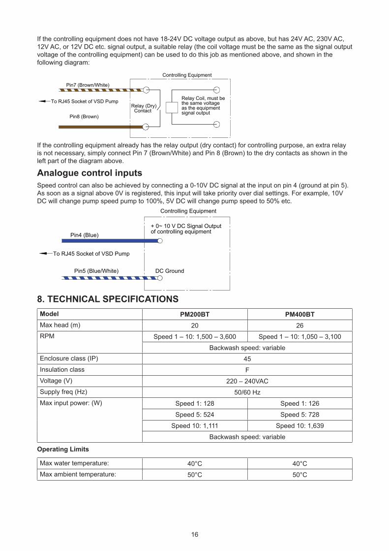
Analogue control inputsSpeed control can also be achieved by connecting a 0-10V DC signal at the input on pin 4 (ground at pin 5). As soon as a signal above 0V is registered, this input will take priority over dial settings. For example, 10V DC will change pump speed pump to 100%, 5V DC will change pump speed to 50% etc.
Pin4 (Blue)
Pin5 (Blue/White)
+ 0~ 10 V DC Signal Output of controlling equipment
DC Ground
Controlling Equipment
To RJ45 Socket of VSD Pump
8. TECHNICAL SPECIFICATIONSModel PM200BT PM400BTMax head (m) 20 26RPM Speed 1 – 10: 1,500 – 3,600 Speed 1 – 10: 1,050 – 3,100
Backwash speed: variableEnclosure class (IP) 45Insulation class FVoltage (V) 220 – 240VACSupply freq (Hz) 50/60 HzMax input power: (W) Speed 1: 128 Speed 1: 126
Speed 5: 524 Speed 5: 728
Speed 10: 1,111 Speed 10: 1,639
Backwash speed: variable
Operating Limits
Max water temperature: 40°C 40°CMax ambient temperature: 50°C 50°C

17
Dimensions
A
C
E
F
G
H
I
D
B
A B C D E F G H IMounting
Holes Diameter
Inlet/Outlet PVC
Net Weight
(kg)
305mm 670mm 320mm 350mm 65mm 230mm 380mm 200mm 250mm 10mm 40/50mm 14
9. USING YOUR PROMASTER WITH A SALT WATER CHLORINATORChlorinators require a minimum flow rate through the chlorinator cell for best efficiency and cell life. Please refer to your chlorinator guide as a reference for the flow required by your pool system. Ensure flow rate is enough to cover your chlorinator cell plates completely at all times of operation.
10. OPERATING YOUR SUCTION POOL CLEANERBefore installing or purchasing a pool cleaner for use with your ProMaster, it is important to know the minimum flow rates required for it to operate effectively.To operate a suction pool cleaner:
• Activate the High Flow setting (10) and allow the pump to fully prime by running for around 2 minutes. You will know the pump is primed when you can see a strong flow of water through the clear leaf basket lid.
• When all air is expelled from the leaf basket, connect the pool cleaner hose firmly into the skimmer plate or dedicated wall suction.
• Select the speed setting that enables best performance from your suction pool cleaner. Speed 3 to 7 should be ample for most cleaners, however if the cleaner requires better performance, select speeds 7 to 10.
• The cleaner should only be connected for as long as is required to clean the surface of your pool. When cleaning is complete, disconnect the cleaner and remove the skimmer plate from the skimmer box.
• Reactivate the most efficient speed setting for daily filtration. Speeds 1 to 4 is recommended.
NOTE: To get optimum energy efficiency from your ProMaster, DO NOT keep the suction pool cleaner connected when cleaning is not required.
NOTE: If the ProMaster is hard-wired into a time clock, or another automatic control, the wiring should be removed by a qualified technician.
• Close the water valves on the pool return and the ProMaster inlet pipework;
• Remove the discharge & suction barrel unions taking care not to lose the o-rings;
• Move the pipework with the barrel unions attached until the ProMaster can be pulled clear.
NOTE: When making any enquiries about your ProMaster be certain to quote the model number from the nameplate located on the motor.

18
11. TROUBLE SHOOTINGIf the pump runs but there is no water flow, or water flow is reduced, the following conditions may apply:
• The filter requires backwashing or it is blocked. Refer to the relevant section in the Filter Manual;
• The pump is not primed. Re-prime as per instruction in ‘Starting the pump’;
• There are air leaks in the suction piping. Check all piping and eliminate leaks, also check for a loose strainer basket lid. Air bubbles in the water flowing back to the pool would indicate a leak in the suction to the pump allowing air to enter the pipework.
• A leaking pump shaft seal may also prevent operation. Evidence of this would be water on the ground under the pump.
• The pump is not able to get water from the pool. Check that the valves to the pump are fully open and that the pool water level is up to the skimmer box. Typically, half way up the face of the skimmer box is sufficient;
• Blockage in the piping or pump. Remove the strainer basket and check for any blockage to the pump impeller entry. Check the skimmer box for blockage.
If the pump does not operate, the following conditions may apply:• The power is not connected. For 220-240 volt only, check the power point by plugging in a portable
appliance to ensure power is available. Also check fuses and the main power supply switch;
• Automatic overload is tripped. The pump has an in-built thermal overload which will reset automatically after the motor has cooled following an overheating period. Determine the cause of the overload tripping and rectify. Reset the pump by switching the power OFF for 30 seconds;
• Blockage is preventing the pump from rotating.
12. REMOVAL OF THE PROMASTER FROM PIPEWORKShould it be necessary to remove the ProMaster, follow these instructions:
• Switch off the power and remove the plug from the power source;
• Unscrew the barrel union on the front and top of the pump, releasing the pump from the pipework;
• Slide the pump out of position.
13. WATER QUALITY
POOL WATER BALANCE Free Chlorine (ppm) pH Total Alkalinity TA
(ppm)
Calcium Hardness
(ppm)
Stabiliser - Cyanuric
Acid (ppm)
Ideal reading/ range 1.5 - 3
Concrete &tiled pools
7.4-7.6Other surfaces
7.2-7.4
80 - 150
Concrete & tiled pools 200-275
Other surfaces 100-225
25-50ppm(15-25ppm if used with
an ORP controller)Not to be used in
indoor pools
To increase
Increase output of sanitiser.
Add chlorine. Increase
filtration time.
Add Soda Ash (Sodium Carbonate)
Add Buffer (Sodium
Bicarbonate)Add Calcium Chloride Add Cyanuric Acid
To decrease
Decrease output of sanitiser. Decrease
filtration time.
Add Hydrochloric Acid
Add Hydrochloric
Acid or Dry Acid
Partially drain & refill pool
with lower hardnesswater to dilute
Partially drain & refill pool
to dilute
Frequencyof testing Weekly Weekly Weekly Weekly Regularly

19
Routine Maintenance tasks - to maximise the life of your pool equipment & personal safety, use this checklist once a week. Turn pump off first.a. Make sure that any pressure gauges are in working condition and the operating
pressure is within limits as specified on the product.b. Make sure that each suction inlet and main drain has a cover that is securely
attached and in safe working condition.c. Make sure that all skimmer covers are securely attached and in safe working
condition. These should be replaced every 3 to 4 years.d. Remove any obstructions or debris from the main drain cover.e. Ensure the skimmer baskets and the pump hair and lint pots are free of leaves and
debris at least once a week.f. Remove obstructions and combustibles from around the pump motor.g. Make sure all wiring connections are clean and that all wiring and electrical
equipment is in good condition. Damaged wiring must be repaired or replaced by a qualified electrician as soon as damage is discovered.
h. Check water balance and sanitiser levels at your local pool shop.
POWER CONNECTIONS AND WIRING MUST BE CARRIED OUT BY AN AUTHORISED ELECTRICIAN.
DANGER Hazardous suction. Do not block water entry into filtration system with any part of your body as the pressure can trap hair or body parts, causing severe injury or death. Do not block suction.Turn off pump immediately if someone becomes trapped.Do not use or operate swimming pools, spas or spa baths if a suction cover is broken, missing or loose. Two suction covers and inlets must be provided into every pump to avoid suction entrapment.
In accordance with AS/NZS60335.2.41 we are obliged to inform you that this device is not to be used by children or infirm persons and must not be used as a toy by children.
CAUTION! Do not add chemicals directly to the pool skimmer. Adding undiluted chemicals may damage pump and filter and void warranty.

AUSTRALIA
Customer Service Centre6 Lakeview Drive,Scoresby, Australia 3179Ph: 1300 232 839Fax: 1300 369 119Email: [email protected]: davey.com.au
Davey Water Products Pty LtdMember of the GUD GroupABN 18 066 327 517
NEW ZEALAND
Customer Service Centre7 Rockridge Avenue,Penrose, Auckland 1061Ph: 0800 654 333Fax: 0800 654 334Email: [email protected]: daveynz.co.nz
® Davey is a registered trademark of Davey Water Products Pty Ltd. © Davey Water Products Pty Ltd 2019. P/N 403301-2
Davey WarrantyDavey Water Products come with guarantees that cannot be excluded under the local country Law. You are entitled to a replacement, or refund for a major failure and compensation for any other reasonably foreseeable loss, or damage. You are also entitled to have the goods repaired or replaced if the goods fail to be of acceptable quality and the failure does not amount to a major failure.
Davey Water Products Pty Ltd (Davey) of 6 Lakeview Drive Scoresby VIC 3179 provides the following warranty in relation this product. Davey warrants that, subject to the exclusions and limitations below, the product will be free from defects in material and workmanship for a period of 36 months from the date of purchase (warranty period).
If a defect appears in the product before the end of the warranty period and Davey finds the product to be defective in materials or workmanship, Davey will, in its sole discretion, either:
1. replace or repair the product or the defective part of the product free of charge; or
2. arrange for the product or the defective part of the product to be repaired or replaced by a qualified repairer free of charge.
Davey reserves the right to replace defective parts of the product with parts or components of similar quality, grade and composition where an identical part or component is not available. Goods presented for repair may be replaced by refurbished goods of the same type rather than being repaired.
Warranty claims:
1. If a fault covered by the warranty occurs, Davey suggests, in the first instance, that you contact the Davey Dealer from whom you purchased the product. Alternatively, you can: phone the Davey Customer Service line on 1300 367 866 in Australia, or 0800 654 333 in New Zealand; send a written letter to Davey at the address listed above; or email [email protected].
2. Any warranty claim must be accompanied by proof of purchase and details of the alleged defect.
3. On receipt of your claim, Davey will seek to resolve your difficulties, or if the product is faulty or defective, advise you on how to have your product repaired, obtain a replacement or a refund.
4. This warranty is limited to defects in the materials or workmanship in the product and does not cover expendable parts or the replacement of parts due to fair wear and tear.
Exclusions:
The warranty will not apply where:
1. The Product has been modified, repaired or serviced by someone other than Davey, or an authorised repairer.
2. Davey cannot establish any fault in the product after testing.
3. The product has been used other than for the purpose for which it was designed.
4. The product has been subject to abnormal conditions, whether of temperature, water, humidity, pressure, stress or similar.
5. The purchaser has used or fitted non-genuine, or non-approved parts and accessories.
6. The Product defect has arisen due to abuse, misuse, neglect or accident.
7. The Product defect has arisen due to the purchaser’s failure to properly maintain or use the product.
8. The damage has been caused by the use of chemicals and detergents not approved by Davey.
Should your Davey product require repair or service after the warranty period, please contact your nearest Davey Dealer, or phone or email the Davey Customer Service Centre. For a complete list of Davey Dealers please visit our website.