Embed Size (px)
Citation preview

masonry. style and function
Structural Design Manual AS 3600:2009
Pronto Block Walls

03Pronto Block Walls | Technical Manual
pronto block wallsdesign manual
Part 1AS 3600:2009
Warwick Colefax BE(Hons) DipTechEng(Struct) MIEAust CPEng RPEQ

4 Austral Masonry
de
sig
n m
an
ua
l Pa
rt 1
– in
tro
du
ctio
n
part 1.introduction
Pronto Block walls are built with dry-stack concrete blocks that are filled with concrete, the dry-stack concrete blocks being precision hollow concrete blocks that are laid without the use of mortar in either the bed joints or the perpends. In Pronto Block construction hollow concrete blocks are interconnected by means of plastic connectors that have the following functions:
– they firmly secure blocks to each other end to end,
– they help correctly position the blocks in the overlying courses, and
– they accurately support horizontal and vertical reinforcement in its correct location.
Pronto Block load bearing walls use specially shaped hollow concrete blocks to construct solid concrete walls. The blocks are essentially used as permanent formwork that contributes some strength to the finished wall. All Pronto Block walls are reinforced and core filled with concrete.
Disclaimer
This Pronto Block design manual has been compiled to assist structural engineers quickly and efficiently prepare designs and details of load-bearing Pronto Block wall structures and elements. Numerous design aids are provided and these cover a broad range of typical design applications. While every care has been taken to ensure the information provided is accurate and complete for the design situations and actions covered, the information should only be used by experienced practicing structural engineers, and all engineers should familiarise themselves with the full contents of the applicable Standards to ensure no requirement is overlooked. Mortarless Pty Ltd, its licensees and the author accept no liability whatsoever arising out of the use or misuse of the information provided in this design manual.
Part 1 of the design manual summarises the provisions of AS 3600:2009 that apply to the design of Pronto Blocks, outlines how it has been applied to the design of Pronto Block walls when preparing the design aids, and provides guidance on all aspects of the structural design.
Parts 2 and 3 of the design manual contain design tables and charts for walls constructed from the range of Pronto Block products. The design aids have been specifically prepared for Pronto Block walls and are not applicable to walls constructed with alternative products.

5Pronto Block Walls | Technical Manual
de
sig
n m
an
ua
l Pa
rt 1
– c
on
ten
ts
Section 1. AS 3600:2009 – Concrete structures
1.1 Overview of AS 3600:2009
1.2 Scope of AS 3600:2009
1.3 Design procedures
1.3.1 Design for strength
1.3.2 Design for serviceability
1.3.3 Design for robustness
1.3.4 Design for durability and fire resistance
1.4 Design Loads
1.4.1 Design loads for Strength Limit State
1.4.2 Design loads for Stability Limit State
1.4.3 Design loads for Serviceability Limit State
1.5 Structural properties
1.5.1 Characteristic compressive strength of Pronto Block walls
1.5.2 Characteristic yield strength of reinforcing steel
1.5.3 Elastic moduli
Section 2. Mortar
Section 3. Reinforcement
3.1 Vertical reinforcement
3.2 Horizontal reinforcement
3.3 Spacing of reinforcement
3.4 Position of reinforcement
3.5 Laps in reinforcement
Section 4. Cover to reinforcement
4.1 Cover for concrete placement
4.2 Cover requirements for durability
4.3 Cover requirements for fire resistance
part 1.contents
Section 5. Core fill grout and grouting
Section 6. Slenderness ratio
6.1 Slenderness ratio for walls
6.2 Slenderness ratio for columns
Section 7. Design for compression
Section 8. Design for bending
8.1 Reinforced Pronto Block walls subject to out-of-plane bending
8,2 Reinforced Pronto Block beams – in-plane bending
Section 9. Design for combined compression and bending
9.1 Axial compression and in-plane bending
9.2 Axial compression and out-of-plane bending
Section 10. Design for tension
Section 11. Design for shear
11.1 Shear resistance of Pronto Block walls in bending
11.2 Shear resistance of Pronto Block walls subject to in-plane lateral load
11.3 Shear resistance of Pronto Block walls subject to out-of-plane shear lateral load

6 Austral Masonry
section 1.2scope of AS 3600:2009
de
sig
n m
an
ua
l Pa
rt 1
– S
ec
tion
1
AS 3600:2009 sets out the minimum requirements for the design and construction of plain and reinforced concrete structures and members. For the purposes of the Standard plain concrete structures are those where the reinforcement, if provided, is ignored for the determination of strength of the structure or member. This is precisely the approach taken for the design of Pronto Block walls in compression.
When designing Pronto Block members to AS 3600, the masonry units are merely considered permanent formwork units that contribute just a little to the strength of the member.
When making calculations for the load tables and diagrams in this manual a small portion of the face shells of the masonry units has been taken as acting in compression and bending. The design thickness of the wall is the overall width of the core fill grout and this is tabulated in Section 1 of Parts 2 and 3. It is this width that has also been used when calculating slenderness ratios.
The core fill concrete in any wall must be of compressive strength at least equal to the unconfined compression strength of the blocks even though that is considered to be possibly conservative. For the purposes of the strength calculation in the design aids in this manual it has been assumed that the grout ƒ’c is at least equal to the strength of the blocks. Grout of greater strength however may be used.

7Pronto Block Walls | Technical Manual
de
sig
n m
an
ua
l Pa
rt 1
– S
ec
tion
1
section 1.3design procedures
AS 3600 Section 2 outlines the requirements for design procedures, actions and loads.
Clause 2.1 sets out the requirements when designing for strength and serviceability, earthquake actions, robustness, durability and fire resistance.
Clause 2.1.1 states that structures shall be designed for ultimate strength and serviceability limit states in accordance generally with the provisions of AS/NZ 1170.0 and the specific requirements of AS 3600 Clauses 2.2 and 2.3.
The limit state method has been used in the generation of all tables and other design aids in this manual.
1.3.1 Design for strengthClause 2.2 outlines the various options for designing members and structures for strength. It is mentioned in Clause 2.2.1 that it is permissible to use different strength check procedures for different members in the one structure, and the structure as a whole, provided it can be shown that all external actions and forces and calculated internal stress resultants are consistent with the requirements for equilibrium and compatibility of the entire structure.
Clause 2.2.2 states that the strength check procedure for use with linear elastic methods of analysis, with simplified methods of analysis, and for statically determinate structures shall be that
Rd ≥ Ed
Where Ru is the ultimate strength of a member Rd is the design capacity (= ØRu), and Ed is the design action effect
This condition must be satisfied at all critical cross sections and regions.
The capacity reduction factors Ø are given in AS 3600 Table 2.2.2.
The ultimate strength of a member (Ru) is to be determined in accordance with AS 3600 using characteristic values for material strengths.
The design action effect (Ed) is to be determined for critical combinations of factored actions specified in AS 1170.0 and AS 3600 Clause 24 by one of the following methods of analysis:
– Linear elastic analysis in accordance with AS 3600 Clause 6.2
– Linear elastic analysis incorporating secondary bending moments due to lateral joint displace-ment in accordance with AS 3600 Clause 6.3
– One of the simplified methods of analysis in accordance with AS 3600 Clauses 6.9 and 6.10.
– Equilibrium analysis of a statically determinate structure.
For strength checks using other methods of analysis refer to AS 3600 Clauses 2.2.3 – 2.2.6, 6.1.1 – 6.1.3 and 6.2 – 6.10.
1.3.2 Design for serviceabilityClause 2.3.1 notes that it is a general requirement that design checks shall be carried out for all appropriate service conditions to ensure the structure will perform in a manner appropriate for its intended function and purpose.
There are no limiting values given for the deflection of walls but limiting values for the deflection of beams are given in Table 2.3.2.
Clause 2.3.2 b) states that members shall be designed such that under serviceability design loads the deflections shall not exceed the deflection limits given in Table 2.3.2. It further states that the deflection may be controlled by limiting the span to depth ratios in accordance with Clause 8.5 for beams and Clause 9.3 for slabs.

8 Austral Masonry
de
sig
n m
an
ua
l Pa
rt 1
– S
ec
tion
1
Clause 2.3.3 states that cracking shall be controlled such that structural performance, durability and appearance are not compromised.
These rules do not generally apply to walls.
1.3.3 Design for robustnessClause 2.1.3 requires that concrete structures be designed to be robust in accordance with the procedures and criteria given in AS 1170.0 Section 6.
AS 1170.0 Section 6 requires structures to be detailed such that all parts of the structure are tied together in both the horizontal and vertical planes so that the structure can withstand an event without being damaged to an extent disproportional to the event. It is further stated in Clause 6.2.1 that this requirement applies to non-structural components as well.
This is a condition that can be readily satisfied with load bearing Pronto Block construction, but a condition that is often not satisfied in column and beam structures and in traditionally detailed residential/domestic structures.
AS 1170.0 Clause 6.2.5 states that:
Walls shall be connected to the structure to provide horizontal resistance to face loads. The connection between the walls and the structure shall be capable of resisting the forces of 5% of G.
It should be borne in mind that this requirement applies to interconnection of the walls to all structural elements including the footings.
1.3.4 Design for durability and fire resistanceClause 2.1.4 requires concrete structures to be designed such that they are durable in accordance with the procedures and criteria given in Section 4, and such
that they are fire resistant in accordance with the procedures and criteria given in Section 5.
All permanent, imposed and other actions are to be in accordance with AS 1170.1.
All wind actions are to be in accordance with AS 1170.2.
All earthquake actions are to be in accordance with AS 1170.4.
All combinations of actions are to be in accordance with AS 117.0 Section 4.

9Pronto Block Walls | Technical Manual
de
sig
n m
an
ua
l Pa
rt 1
– S
ec
tion
1
section 1.4design actions
1.4.1 Combinations of actions for Strength Limit State Basic combinations:
i) Ed = 1.35G permanent action only
ii) Ed = 1.2G + 1.5Q permanent and imposed action
iii) Ed = 1.2G = 1.5ΨlQ permanent and long term imposed action
iv) Ed = 1.2G + Wu + ΨcQ permanent, wind and imposed action
v) Ed = 0.9G + Wu permanent and wind action reversal
vi) Ed = G + Eu + ΨEQ permanent, earthquake and imposed action
vii) Ed = 1.2G + Su + ΨcQ permanent action, actions given in AS 1170.0 Clause 4.2.3 and imposed action
where G, Q, Wu and Eu are the permanent action, imposed action, ultimate wind action, and ultimate earthquake action respectively,
and where for distributed imposed actions Q
Ψc and Ψl = 0.4 for domestic, office, parking, retail floors
= 0.6 for storage and other floors
= 0.4 for trafficable roofs
= 0.0 for non-trafficable roofs
ΨE = 0.3 for domestic, office, parking, retail floors
= 0.6 for storage and other floors
= 0.3 for trafficable roofs
= 0.0 for non-trafficable roofs
Refer to AS 1170.0 Table 4.1 for the factors applicable to concentrated imposed actions.
Refer to AS 1170.0 Clause 4.2.3 for Su.
1.4.2 Combinations of actions for Stability Limit StateFor combinations that produce net stabilizing effects (Ed,stb):
Ed,stb = 0.9G permanent action only
For combinations that produce net destabilizing effects (Ed,dst):
i) Ed,dst = 1.35G permanent action only
ii) Ed,dst = 1.2G + 1.5Q permanent and imposed action
iii) Ed,dst = 1.2G + Wu + ΨcQ permanent, wind and imposed action
iv) Ed,dst = G + Eu +ΨEQ permanent, earthquake and imposed action
v) Ed,dst = 1.2G + Su + ΨcQ permanent action, actions given in AS 1170.0 Clause 4.2.3 and imposed action
1.4.3 Combinations of actins for Serviceability Limit StateFor short-term and long-term effects, combinations that include one or more of the following:
i) G
ii) ΨsQ
iii) ΨlQ
iv) Ws
v) Es
vi) Serviceability values of other actions, as appropriate.
Where Ψs and Ψl are the short-term and long-term imposed action factors respectively, which are given in AS 1170.0 Table 4.1

10 Austral Masonry
section 1.5structural properties
de
sig
n m
an
ua
l Pa
rt 1
– S
ec
tion
1
1.5.1 Characteristic compressive strength of mortarless wallsThe adopted value for the compressive strength of the composite masonry unit and the core fill concrete is the characteristic compressive (cylinder) strength of the core fill concrete but not greater than the unconfined compressive strength of the masonry face shells. Note that the minimum cylinder strength of the core fill concrete (grout) is to be not less than the unconfined compressive strength of the face shells of the blocks.
1.5.2 Characteristic yield strength of reinforcing steel, ƒsy
The design tables in this manual are based on the use of reinforcing steel with a characteristic yield strength of 500 MPa.
1.5.3 Elastic ModuliThe modulus of elasticity of the core fill grout (Ec) at 28 days is as follows (Clause 3.1.2):
Ec = 20,500 MPa for 15MPa Grout
Ec = 24,000 MPa for 20MPa Grout
Ec = 26,700 MPa for 25MPa Grout
It is noted in Clause 3.1.2 that consideration should be given to the fact that the above values have a range of +/- 20%.
The elastic modulus of steel reinforcement Es = 200,000 MPa.

11Pronto Block Walls | Technical Manual
de
sig
n m
an
ua
l Pa
rt 1
– S
ec
tion
2
section 2.mortar
Mortar is not generally used with Pronto Block, however it is recommended that the first course of blocks be always bedded in mortar in order to correct any unevenness or level issues in the slab or footings and to provide the maximum bearing width at the base of the wall. Mortar type M4 (refer Table 10.1 in AS 3700) should be used for this purpose.
In situations where loads are minimal it may not be necessary to bed the bottom course. This is the exception however rather than the rule.

12 Austral Masonry
section 3.reinforcement
de
sig
n m
an
ua
l Pa
rt 1
– S
ec
tion
3
The reinforcement in Pronto Block walls designed to AS 3600:2009 needs to comply with the minimum requirements outlined in Clause 11.7. When calculating the minimum reinforcement requirements the thickness of the Pronto Block wall should be taken as the design thickness given in the Properties Table in Section 1 of the subsequent parts of this manual.
3.1 Vertical reinforcementThe vertical reinforcement is not considered as contributing the compression load capacity of a Pronto Block wall and that is because it cannot be tied in the way that that prevents premature buckling of the bars (refer Clauses 10.7.2 and 10.7.4). Note however that Clause 11.7.4 states that it is not necessary to restrain the vertical reinforcement if:
N* ≤ 0.5 ØNu , or
the vertical reinforcement is not used as compressive reinforcement, or
the vertical reinforcement ratio is not greater than 0.01 and a minimum horizontal reinforcement ratio of 0.0025 is provided.
This means that generally, in terms of compliance with AS 3600, the vertical reinforcement could be considered to contribute to the axial load capacity of a Pronto Block wall and therefore the values in the load tables are generally a little conservative.
Clause 11.7.1 requires a minimum reinforcement ratio of 0.0015, i.e. 0.15% of the cross sectional area (refer first paragraph above). The area of reinforcement however must be adequate to satisfy the strength requirements.
3.2 Horizontal reinforcementClause 11.7.1 requires a minimum reinforcement ratio of 0.0025, i.e. 0.25% of the cross sectional area (refer first paragraph above). As for the vertical reinforcement however the area of reinforcement must also be adequate to satisfy the strength requirements.
It is noted in 11.7.1 that the minimum ratio may be reduced to 0.0015 if the wall is being designed for one-way buckling using Clause 11.4(a). It further states that the minimum reinforcement ratio may be reduced to zero when there is no restraint to horizontal shrinkage or thermal movements and the length of the wall is less than 2.5m, or 0.0015 when there is no restraint against horizontal shrinkage or thermal movements and the length of the wall is equal to or greater than 2.5m.
Clause 11.7.2 provides further requirements for minimum reinforcement ratios in terms of exposure classifications and crack control. The requirements are as follows:
Reinf’t Ratio Exposure Classification
Degree of control over cracking
0.0025 A1 & A2 Minor
0.0035 A1 & A2 Moderate and where cracks are inconsequential or hidden from view
0.006 A1 & A2 Strong – for appearance and where cracks may reflect through finishes
0.006 B1, B2, C1, C2 All
It is also noted in Clause 11.7.2 that additional horizontal crack control reinforcement may be needed at the base of the wall to control thermal cracking during hydration for walls longer than 8m. The author is of the opinion that this is not applicable to Pronto Bock walls.
3.3 Spacing of reinforcementClause 11.7.3 gives guidance on the maximum spacing of reinforcement. The maximum clear spacing is given as the lesser of 2.5tw and 350mm. As mentioned above the design thickness of a Pronto Block wall (td) is the value given in the section properties tables in the subsequent Parts of this manual and for the purposes of this calculation td should be substituted for tw.
With Pronto Block construction the spacing of vertical and horizontal reinforcement can only be in increments of 200mm, i.e. 200, 400, 600 etc. This is something the
13Pronto Block Walls | Technical Manual
de
sig
n m
an
ua
l Pa
rt 1
– S
ec
tion
3
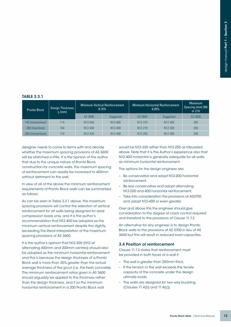
designer needs to come to terms with and decide whether the maximum spacing provisions of AS 3600 will be stretched a little. It is the opinion of the author that due to the unique nature of Pronto Block construction for concrete walls, the maximum spacing of reinforcement can readily be increased to 400mm without detriment to the wall.
In view of all of the above the minimum reinforcement requirements of Pronto Block walls can be summarized as follows:
As can be seen in Table 3.3.1 above, the maximum spacing provisions will control the selection of vertical reinforcement for all walls being designed for axial compression loads only, and it is the author’s recommendation that N12-400 be adopted as the minimum vertical reinforcement despite this slightly exceeding the literal interpretation of the maximum spacing provisions of AS 3600.
It is the author’s opinion that N12-300 (N12 at alternating 400mm and 200mm centres) should also be adopted as the minimum horizontal reinforcement and this is because the design thickness of a Pronto Block wall is more than 20% greater than the actual average thickness of the grout (i.e. the fresh concrete). The minimum reinforcement ratios given in AS 3600 should arguably be applied to this thickness rather than the design thickness, and if so the minimum horizontal reinforcement in a 200 Pronto Block wall
would be N12-330 rather than N12-250 as tabulated above. Note that it is the Author’s experience also that N12-400 horizontal is generally adequate for all walls as minimum horizontal reinforcement.
The options for the design engineer are:
– Be conservative and adopt N12-200 horizontal reinforcement,
– Be less conservative and adopt alternating N12-200 and 400 horizontal reinforcement,
– Take into consideration the provisions of AS3700 and adopt N12-400 or even greater.
Over and above this the engineer should give consideration to the degree of crack control required and therefore to the provisions of Clause 11.7.2.
An alternative for any engineer is to design Pronto Block walls to the provisions of AS 3700 in lieu of AS 3600 but this will result in reduced load capacities.
3.4 Position of reinforcementClause 11.7.3 states that reinforcement must be provided in both faces of a wall if:
– The wall is greater than 200mm thick,
– If the tension in the wall exceeds the tensile capacity of the concrete under the design ultimate loads,
– The walls are designed for two way buckling (Clauses 11.4(b) and 11.4(c)).
Pronto Block Design Thickness td (mm)
Minimum Vertical Reinforcement 0.15%
Minimum Horizontal Reinforcement 0.25%
Maximum Spacing (mm) 350
or 2.5t
AS 3600 Suggested AS 3600 Suggested AS 3600
140 Unchamfered 114 N12-640 N12-600 N12-310 N12-400 285
200 Chamfered 164 N12-450 N12-400 N12-270 N12-300 350
200 Unchamfered 174 N12-420 N12-400 N12-250 N12-300 350
TABLE 3.3.1

14 Austral Masonry
de
sig
n m
an
ua
l Pa
rt 1
– S
ec
tion
3
3.5 Laps in reinforcementThe lap length for splicing bars in tension is given in Clause 13.2.2 as follows:
Lsy.t.lap = k7 Lsy.t ≥ 29k1db
Where: Lsy.t is calculated in accordance with Clause
13.1.2.1, and
k7 is to be taken as 1.25 unless the area of steel provided is at least twice the area required and no more than half of the reinforcement at the section spliced in which case it can be taken as 1.
Accordingly a minimum lap length of 36.25 bar diameters applies and for N12 bars this is 435mm but say 450mm.
When calculating the basic development length in accordance with Clause 13.1.2.2 the following values result:
Development length L sy.tb calculated in accordance with Clause 13.1.2.2
20MPa concrete 25MPa concrete
N12 vertical bars 390 350
N12 horizontal bars 510 455
N16 vertical bars 540 485
Assuming k7 = 1.25 as is normally the case, the minimum lap lengths are as follows:
Lap length L sy.tb.lap calculated in accordance with Clause 13.2.2 (mm)
20MPa concrete 25MPa concrete
N12 vertical bars 490 440
N12 horizontal bars 640 570
N16 vertical bars 675 605
Clause 13.2.2 states that the tabulated lap lengths apply to both contact and non-contact splices. Note that Clause 13.2.1 states that lap splices shall not be used in tension tie members; in these members splices must be made only by welding or mechanical means.
15Pronto Block Walls | Technical Manual
de
sig
n m
an
ua
l Pa
rt 1
– S
ec
tion
4
A fundamental and most critical aspect of the durability of any reinforced concrete member or any masonry member containing reinforcement is the provision of adequate cover. Adequate cover is also an important aspect of achieving the necessary fire resistance period (FRP) with respect to structural adequacy.
Clause 4.10.1 states that the cover to any bar shall be the greatest of the values determined for proper concrete placement, durability and fire protection.
4.1 Cover for concrete placementClause 4.10.2 states that the cover shall be adequate to ensure concrete can completely fill the formwork and closely surround the reinforcement. In general this means that cover shall not be less than the larger of the size of the reinforcing bar or the maximum nominal aggregate size.
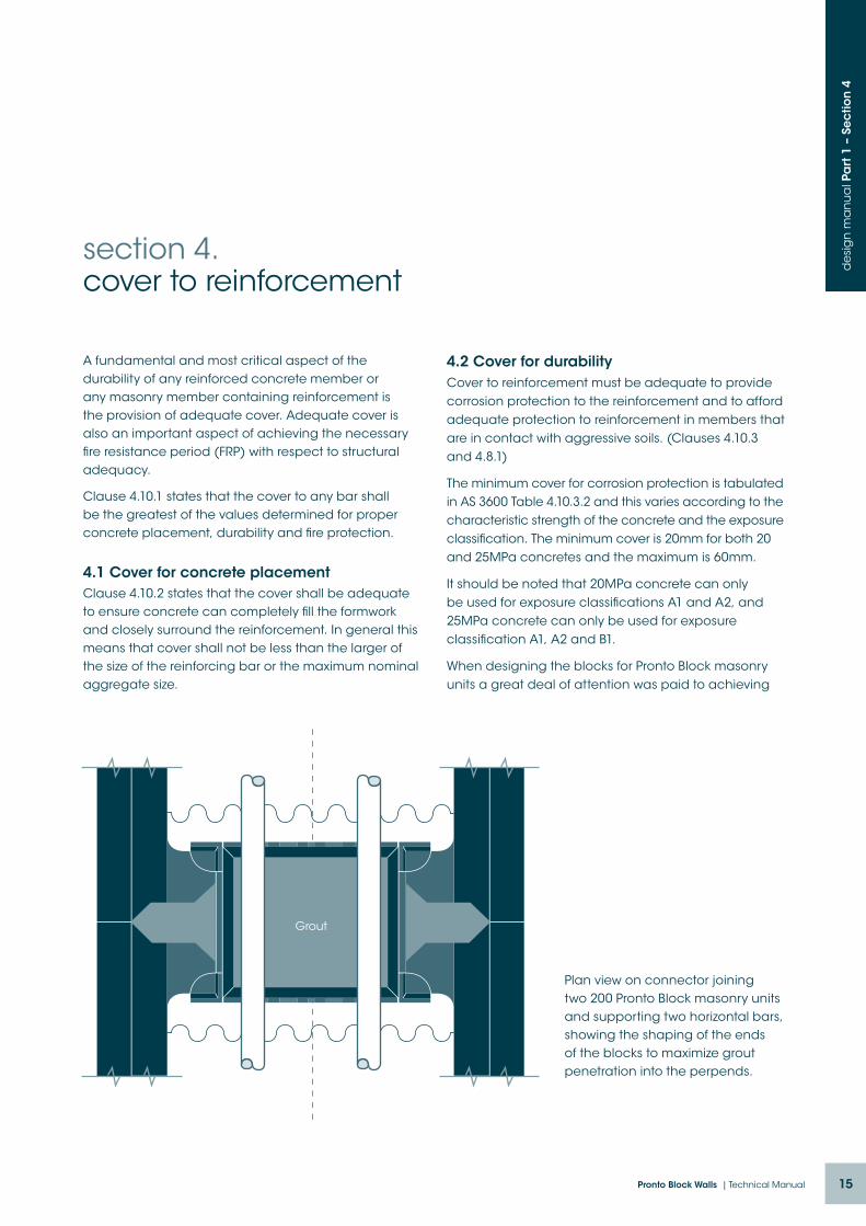
Plan view on connector joining two 200 Pronto Block masonry units and supporting two horizontal bars, showing the shaping of the ends of the blocks to maximize grout penetration into the perpends.
section 4.cover to reinforcement
4.2 Cover for durabilityCover to reinforcement must be adequate to provide corrosion protection to the reinforcement and to afford adequate protection to reinforcement in members that are in contact with aggressive soils. (Clauses 4.10.3 and 4.8.1)
The minimum cover for corrosion protection is tabulated in AS 3600 Table 4.10.3.2 and this varies according to the characteristic strength of the concrete and the exposure classification. The minimum cover is 20mm for both 20 and 25MPa concretes and the maximum is 60mm.
It should be noted that 20MPa concrete can only be used for exposure classifications A1 and A2, and 25MPa concrete can only be used for exposure classification A1, A2 and B1.
When designing the blocks for Pronto Block masonry units a great deal of attention was paid to achieving
Grout

16 Austral Masonry
de
sig
n m
an
ua
l Pa
rt 1
– S
ec
tion
4
satisfactory cover to the embedded reinforcement. This is a most important structural aspect that is overlooked in all similar dry-stack systems.
Most dry-stack systems provide totally inadequate cover in the vicinity of the perpends and many also provide totally inadequate cover in the vicinity of the bed joints but this issue has been addressed in the internal shaping of Pronto Block masonry units.
4.3 Cover requirements for fire resistanceAS 3600 Clause 5.7 outlines the requirements for walls when assessing the FRP.
Insulation:AS 3600 Table 5.7.1 gives the FRP for walls of various effective thicknesses. 140 Pronto Block walls would achieve an FRP of 120 minutes and 200 Pronto Block walls would achieve an FRP of 240 minutes without the addition of suitable insulation material (refer Clause 5.8.1).
Structural Adequacy:The values for the full range of FRPs are given in AS 3600 Table 5.7.2 and these are for walls exposed to fire on either one or both sides.
To satisfy the structural adequacy provisions a wall must have an axis distance of 10mm for 30 minutes FRP and 55mm or 60mm for 240 minutes FRP. The axis distance is the cover to the longitudinal steel plus half of the bar diameter. Pronto Block masonry units are designed to achieve the maximum required axis distance for all reinforcement.
It should be noted that the required thickness of a wall for any particular FRP increases as the ratio of the applied load to the load capacity increases.
For compliance with Table 5.7.2 a 140 Pronto Block wall would not achieve an FRP greater than 90 minutes and a 200 Pronto Block wall would not achieve an FRP greater than 180 minutes.
Maximum Slenderness Ratio:Clause 5.7.3 states that any wall required to have an FRP must have a slenderness ratio (ratio of effective height to thickness) not exceeding 40.
Clause 5.7.4 outlines the effect that chases have on the FRP of any wall. The design engineer needs to give careful consideration to walls designed as spanning in two directions.

17Pronto Block Walls | Technical Manual
de
sig
n m
an
ua
l Pa
rt 1
– S
ec
tion
5
All Pronto Block walls and piers must be fully grouted regardless of whether or not they are reinforced, as it is the grout that permanently bonds the masonry units to each other. Although most Pronto Block elements will contain reinforcement, minor structures such as drainage pits and temporary in-ground works may not need to be reinforced.
Core filling grout must be a free flowing concrete with a small sized coarse aggregate. Typically core filling grout is specified as 20MPa or 25MPa with maximum 5mm or 7mm coarse aggregate and about 230 slump. This is achieved by means of a super plasticiser additive.
Concretes with such a high slump are sometimes more appropriately specified with a spread rather than a slump and a spread of about 600mm is the equivalent.
The 28-day cylinder strength of the grout should be at least equal to the unconfined compressive strength of the face shells of the masonry units but may be increased for enhanced corrosion protection and
section 5.core fill grout and grouting
it is recommended that a minimum 20MPa grout be used in any Pronto Block wall.
The grout must have pouring consistency that enables the cores or cavities to be completely filled and reinforcement to be completely surrounded without segregation of the constituents. The super plasticised mix readily achieves this objective and thoroughly wetting the block cores immediately prior to grouting is also essential.
Grout should not be compacted by mechanical vibration as this can result in failure of face shells. As stated above it is recommended that all block cores be thoroughly wetted down immediately prior to grouting and it is also recommended that the grout be compacted by rodding only to remove any trapped air.
Upon completion of the last lift of Pronto Block walling, the grout should be topped up after a waiting period of 10 to 30 minutes and lightly rodded to merge the top up grout with the previous pour.

18 Austral Masonry
de
sig
n m
an
ua
l Pa
rt 1
– S
ec
tion
6
Slenderness ratio of a wall is the ratio of the effective height of a wall divided by the thickness. It provides a means of measuring the robustness of a wall and it is used in calculations to adjust the capacity of a wall to account for the possibility of buckling causing a premature mode of failure.
6.1 Slenderness ratio for Pronto Block wallsAS 3600 Clause 11.2 outlines the design procedures for walls and the limiting slenderness ratio depends on the design method being used (refer Section7):
a) For braced walls designed using the simplified method the maximum slenderness ratio is 30.
b) For braced walls designed as a slab the maximum slenderness ratio is 50 (refer Clause 11.1(b)).
c) For walls designed as columns see below.
AS 3600 Clause 11.5 contains provisions for the design of walls for vertical compression forces using a simplified design method where the slenderness ratio does not exceed 30. The values in the design tables in the subsequent parts of this manual have been calculated using the simplified method.
Clause 11.4 gives the method of calculating effective height (Hwe) depending on whether one-way or two- way buckling applies to the design. In all cases Hwe = kHw where:
Hw is the unsupported height of a wall, and
L1 is the length of a wall between centres of lateral restraint or from a lateral restraint to a free edge.
There are three different circumstances for braced walls in which the value of k varies:
1. one-way buckling k = 0.75 for braced walls where rotational restraint is provided at both ends, and k = 1.0 where rotational restraint is not provided at one or both ends.
2. two-way buckling with lateral support provided on three sides by floors and
section 6.slenderness ratio
intersecting walls k = 1/ (1+ (Hw
2/9L12)) but not less than 0.3
and not greater than k for one-way buckling
3. two-way buckling with lateral support provided on four sides by floors and intersecting walls k = 1/(1+(Hw
2 / L12)) where Hw ≤ L1
k = L1 / 2Hw where Hw > L1
Note that if a wall is designed for two way buckling then both the vertical and the horizontal reinforcement must be positioned in both faces – refer Section 3 of this design manual.
For walls with openings there two circumstances to be considered (Clause 11.4):
a) If the total area of the openings is less than 10% of the area of the wall and the height of any opening (not vertically one above the other) is less than 1/3rd of the height of the wall, then the effect of the openings can be ignored.
b) In other cases the area of the wall between the support and the opening shall be designed as supported on three sides, and the area between openings shall be designed as supported on two sides.
In Clause 11.4 it is stated that an intersecting wall with a minimum length of 0.2Hw can be considered a lateral restraint.
6.2 Slenderness ratio for columnsFor walls designed as columns the maximum slenderness ratio as defined in Clause 10.3.1 must not exceed 120 unless a rigorous analysis has been carried out (Clause 10.5.1).
The method of calculating the effective length of a column is given in Clause 10.5.3, and the means of calculating the slenderness ratio is given in the other parts of Clause 10.5. Note that the slenderness ratio of a column is the effective length divided by the radius of gyration.

19Pronto Block Walls | Technical Manual
de
sig
n m
an
ua
l Pa
rt 1
– S
ec
tion
7
When designing Pronto Block walls and piers for compression loads the vertical reinforcement is not considered to make any contribution to the compressive strength simply because it cannot be restrained in two directions with ties at close centres.
It is normal practice when designing reinforced concrete walls to neglect any contribution the reinforcement might make to the compression load capacity, however AS 3600 Clause 11.7.4 permits the contribution of unrestrained vertical reinforcement if the area of reinforcement in certain circumstances – refer 3.1 above. In all of the design aids in this manual any contribution of the reinforcement to the vertical load capacity has been ignored.
Design of Proto Block walls in axial compressionThe design strength of a wall in compression is dependent on the following:
– Slenderness
– Effective eccentricity at the top
– Characteristic compressive strength of the masonry and the grout
– Cross sectional area of the masonry.
In Pronto Block wall construction the Pronto Block masonry units are permanent shutters or formwork that contribute just a little to the compressive strength of the wall. The design thickness is less than the total thickness; it is just the overall thickness of the grout (concrete core fill). The portion of the masonry face shells that have no provision for concrete penetration are ignored. In unchamfered Pronto Block that generally means that 26mm of the wall thickness is ignored and in chamfered Pronto Block it means that 36mm of the thickness is ignored.
AS 3600 Clause 11.2 outlines the design procedures for walls and there are various options:
section 7.design of pronto block walls for compression
For braced walls where there are in-plane horizontal forces acting in conjunction with axial forces and where these are such that a horizontal cross section of the wall is subject to compression over the entire section then the in-plane bending can be neglected and the wall designed for the horizontal shear forces as per Section 5 in Parts 2 and 3 of this design manual. In this circumstance the wall can be designed for vertical compression forces either
a) as a wall in accordance with the simplified procedure provided the slenderness ratio does not exceed 30, or
b) as a column in accordance with AS 3600 Section 10 with vertical reinforcement provided in both faces (but with no requirement to consider the contribution of the vertical reinforcement to the compression load capacity).
For braced walls that are subject to simultaneous in-plane and out-of-plane load effects, and for unbraced walls, AS 3600 Clause 11.1(b) requires that they be designed as slabs in accordance with Section 9 or columns in accordance with Section 10 as appropriate.
It further states that where the stress at the mid-height section due to factored in-plane bending and axial forces does not exceed the lesser of 0.03ƒ’c and 2MPa, then the wall may be designed as a slab in accordance with Section 9 provided:
i) the second-order deflections due to in-plane loads and long-term effects are considered in the calculation of bending moments, and
ii) the ratio of effective height to thickness does not exceed 50.
All of the axial compression load values in the design tables in the subsequent Parts of this manual have been calculated using the simplified method.

20 Austral Masonry
de
sig
n m
an
ua
l Pa
rt 1
– S
ec
tion
7
The values used in the interaction diagrams however have been calculated using column design formulae. When using the interaction diagrams it is essential that a proper analysis be completed.
Simplified design method for walls in axial compressionNote that this method of design is permitted for walls in which the slenderness ratio does not exceed 30.
Clause 11.5.1 states that the design axial strength per unit length of a braced wall in compression can be taken as ØNu
Where Ø = 0.6 and
Nu = 0.6ƒ’c(tw – 1.2e –2ea)
In the above e is the eccentricity of the load measured at right angles to the plane of the wall, and ea is the additional eccentricity taken as (Hwe)2/2500tw
The method of calculating the eccentricity e at the top of a wall when using the simplified method is given in Clause 11.5.2 and this is also shown in detail in the subsequent parts of this manual.
The minimum eccentricity on any wall designed using this method is 5% of the wall thickness, i.e.0.05td.
Design for compression in mortarless shear wallsWhen a load-bearing wall is also acting as a shear wall, in plane bending should be checked. When a horizontal force is resisted by more than one shear wall, the load may be distributed between the walls in proportion to their flexural stiffness about an axis perpendicular to the plane of the wall.
The in-plane bending moment will result in non-uniform compression in the wall and the wall should be designed for the maximum resulting compression force.
AS 3600 Clause 11.2.1 states that in-plane bending may be neglected in the case where the horizontal cross section is always under compression due to the combined effect of horizontal and vertical loads, and the wall be simply designed for axial load and for shear. It is recommended by the author however that the maximum compression in any wall due to the combined loading always be considered.
Clause 11.2.1 further states that if any part of a wall is subject to tension due to in-plane bending then the wall shall be designed for in-plane bending in accordance with Section 8 and for horizontal shear in accordance with Clause 11.6, or for in-plane bending and shear in accordance with Section 12 if appropriate.
Bearing StressAS 3600 Clause 12.6 should be used for checking the bearing stress at load concentrations.

21Pronto Block Walls | Technical Manual
de
sig
n m
an
ua
l Pa
rt 1
– S
ec
tion
8
All Pronto Block walls are fully grouted and they are readily reinforced with certainty of the reinforcement positioning within. As such they can readily be designed for flexure as members spanning vertically, horizontally or both.
8.1 Reinforced Pronto Block walls subject to out-of-plane bending:The provisions of AS 3600 Section 9 (Design of Slabs for Strength and Serviceability) are used for the design of Pronto Block walls for out-of-plane bending.
Clause 9.1.1 refers back to Clauses 8.1.1 through 8.1.8 for determining the strength of a one-way slab in bending. Clause 8.1.2 outlines the assumptions used when calculating the strength in bending which incorporates equilibrium and strain-compatibility considerations, and Clause 8.1.3 provides the deemed to satisfy provisions using a rectangular compression stress block. These can be summarized as follows:
a) Plane sections normal to the axis remain plane after bending;
b) The concrete has no tensile strength;
c) Compressive stress distribution is represented by an equivalent rectangle where the stress is α2ƒ’c and the depth of the compression block is γkud where
α2 = 1.0 – 0.003ƒ’c (within the limits 0.67 ≤ α2 ≤ 0.85) γ = 1.05 – 0.007ƒ’c (within the limits 0.67 ≤ γ ≤ 0.85)
d) The maximum strain in the outermost compression fibre is taken as 0.003;
AS 3600 Clause 11.1(b) permits the design of walls simply as slabs in accordance with the appropriate provisions of Section 9 provided the stress at the mid-height section of the wall due to factored in- plane bending and axial forces does not exceed the lesser of 0.03ƒ’c and 2MPa, provided the second-order deflections due to in-plane loads and long-term effects
section 8.design of pronto block walls for bending
are considered in the calculation of bending moments, and provided the slenderness ratio (using effective height) does not exceed 50.
8.2 Reinforced Pronto Block beams, i.e. Pronto Block walls subject to in-plane bending:The recommended limiting span to effective depth ratios for beams are as follows:
– 20 for simply supported beams,
– 26 for continuous beams, and
– 7 for cantilever beams.
The cross section should be designed in accordance with the provisions of AS 3600 Section 8. Special consideration needs to be given to the detailing of any required shear reinforcement.

22 Austral Masonry
de
sig
n m
an
ua
l Pa
rt 1
– S
ec
tion
9
Section 7 of this design manual deals with the design of Pronto Block walls for compression which are always designed for bending moments due to eccentricity of the applied load and for additional bending moments due to the eccentricity caused by slenderness effects. In addition to these two bending moments however, walls can also be subjected to out-of-plane lateral loads and therefore additional bending moments. A typical example of such a wall is a perimeter load-bearing wall in a building that is also a retaining wall.
In walls subjected to both compression and bending, compressive stress in the concrete can govern the design in situations where the compression stress due to axial load is high and the applied bending moment is sufficient to increase the compressive stress in the concrete (at the extreme fibre) to the point where it fails. In such circumstances the entire section can still be in compression and tensile reinforcement plays no direct role in the strength of the wall.
The other extreme is where the axial compression load is low and the wall fails in flexure through excessive tension in the reinforcement. The wall is essentially a vertical slab and can be designed as a slab.
9.1 Axial compression and in-plane bendingAS 3600 Clause 11.2 covers the situation in which the bending results from in-plane lateral loads e.g. load-bearing shear walls in buildings. It states that where the entire horizontal cross section of the wall remains in compression then the in-plane bending in the wall can be ignored and the wall simply designed for axial compression as outlined in Section 7 of this manual and for in-plane shear as outlined in Section 11 of this manual.
If the in-plane bending is such that parts of the walls horizontal cross section are in tension then reinforcement must be provided to accommodate the tensile forces. The masonry and the grout cannot be designed for such tensile forces.
section 9.design for combined compression and bending
9.2 Axial compression and out-of-plane bendingAS 3600 Clause 11.1(b) states that when walls are subject to axial compression plus out-of-plane bending they can be designed as slabs – refer 8.1 above
When the axial compression load is larger than that which produces the limiting compressive stress for the application of 11.1(b) then it is necessary to consider the combined effect to ensure that neither the concrete in compression nor the steel reinforcement in tension is overstressed. This is referred to in Clause 10.6.1 for columns in which it is stated that the compression member shall be designed on the basis of Clauses 10.6.1 and 10.6.2.
Clause 10.6.1 outlines the basic assumptions for limit state design of a section, viz that plane sections remain plane, that the concrete has no tensile strength, that the distribution of stress in the concrete and the steel is determined using the stress-strain relationship determined from Clauses 3.1.4 and 3.2.3 respectively, and that when the neutral axis lies outside the cross section consideration should be given to the effect on strength of spalling of the concrete cover.
The maximum strain in the concrete in the extreme compression fibre is given in Clause 8.1.2 as 0.003.
Interaction diagrams are provided in the subsequent Parts of this design manual for the purpose of checking combined axial compression and out-of-plane bending.
Note that when using the interaction diagrams a proper analysis should be carried out to determine the bending moments at the critical sections and these must include the bending moments due to secondary effects.

23Pronto Block Walls | Technical Manual
de
sig
n m
an
ua
l Pa
rt 1
– S
ec
tion
10
Any Pronto Block member designed to resist axial tension must be reinforced as it is only the reinforcement that carries the tensile load.
There are no provisions in AS 3600 for the design of members in direct tension. There is however a section (AS 3600, section 7) on strut and tie modeling of structures, and Clause 7.3.2 provides guidance on the design of ties.
Refer also to Section 3 of Part 1 of this design manual for information on splicing reinforcement in tension members.
It is recommended by the author that walls should not generally be used in situations where they will be subjected to direct tension.
section 10.design for tension
24 Austral Masonry
de
sig
n m
an
ua
l Pa
rt 1
– S
ec
tion
11
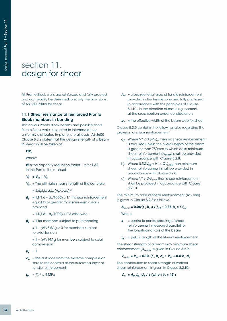
All Pronto Block walls are reinforced and fully grouted and can readily be designed to satisfy the provisions of AS 3600:2009 for shear.
11.1 Shear resistance of reinforced Pronto Block members in bendingThis covers Pronto Block beams and possibly short Pronto Block walls subjected to intermediate or uniformly distributed in-plane lateral loads. AS 3600 Clause 8.2.2 states that the design strength of a beam in shear shall be taken as:
ØVu
Where:
Ø is the capacity reduction factor – refer 1.3.1 in this Part of the manual
Vu = Vuc + Vus
Vuc = The ultimate shear strength of the concrete
= ß1ß2ß3bvdofcv(Ast/bvdo)1/3
β1 = 1.1(1.6 – do/1000) ≥ 1.1 if shear reinforcement equal to or greater than minimum area is provided
= 1.1(1.6 – do/1000) ≥ 0.8 otherwise
β2 = 1 for members subject to pure bending
= 1 – (N*/3.5Ag) ≥ 0 for members subject to axial tension
= 1 – (N*/14Ag) for members subject to axial compression
β3 = 1
do = the distance from the extreme compression fibre to the centroid of the outermost layer of tensile reinforcement
fcv = ƒ’c1/3 ≤ 4 MPa
section 11.design for shear
Ast = cross-sectional area of tensile reinforcement provided in the tensile zone and fully anchored in accordance with the principles of Clause 8.1.10., in the direction of reducing moment, at the cross section under consideration
bv = the effective width of the beam web for shear
Clause 8.2.5 contains the following rules regarding the provision of shear reinforcement:
a) Where V* ≤ 0.5ØVuc then no shear reinforcement is required unless the overall depth of the beam is greater than 750mm in which case minimum shear reinforcement (Asv.min) shall be provided in accordance with Clause 8.2.8.
b) Where 0.5ØVuc < V* ≤ ØVu.min then minimum shear reinforcement shall be provided in accordance with Clause 8.2.8.
c) Where V* > ØVu.min then shear reinforcement shall be provided in accordance with Clause 8.2.10
The minimum area of shear reinforcement (Asv.min) is given in Clause 8.2.8 as follows:
Asv.min = 0.06√ƒ’c bv s / fsy.f ≥ 0.35 bv s / fsy.f
Where:
s = centre to centre spacing of shear reinforcement measured parallel to the longitudinal axis of the beam
fsy.f = yield strength of the fitment reinforcement
The shear strength of a beam with minimum shear reinforcement (Asv.min) is given in Clause 8.2.9:
Vu.min = Vuc + 0.10 √ƒ’c bv do ≥ Vuc + 0.6 bv do
The contribution to shear strength of vertical shear reinforcement is given in Clause 8.2.10:
Vus = Asv fsy.f do / s (when θv = 45̊ )
25Pronto Block Walls | Technical Manual
de
sig
n m
an
ua
l Pa
rt 1
– S
ec
tion
11
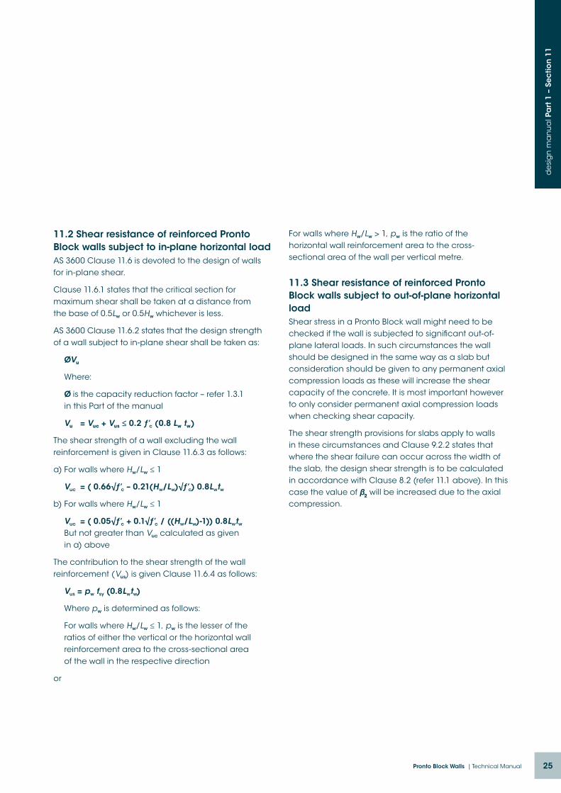
11.2 Shear resistance of reinforced Pronto Block walls subject to in-plane horizontal loadAS 3600 Clause 11.6 is devoted to the design of walls for in-plane shear.
Clause 11.6.1 states that the critical section for maximum shear shall be taken at a distance from the base of 0.5Lw or 0.5Hw whichever is less.
AS 3600 Clause 11.6.2 states that the design strength of a wall subject to in-plane shear shall be taken as:
ØVu
Where:
Ø is the capacity reduction factor – refer 1.3.1 in this Part of the manual
Vu = Vuc + Vus ≤ 0.2 ƒ’c (0.8 Lw tw)
The shear strength of a wall excluding the wall reinforcement is given in Clause 11.6.3 as follows:
a) For walls where Hw/Lw ≤ 1
Vuc = ( 0.66√ƒ’c – 0.21(Hw/Lw)√ƒ’c) 0.8Lwtw
b) For walls where Hw/Lw ≤ 1
Vuc = ( 0.05√ƒ’c + 0.1√ƒ’c / ((Hw/Lw)-1)) 0.8Lwtw But not greater than Vuc calculated as given in a) above
The contribution to the shear strength of the wall reinforcement (Vus) is given Clause 11.6.4 as follows:
Vus = pw fsy (0.8Lwtw)
Where pw is determined as follows:
For walls where Hw/Lw ≤ 1, pw is the lesser of the ratios of either the vertical or the horizontal wall reinforcement area to the cross-sectional area of the wall in the respective direction
or
For walls where Hw/Lw > 1, pw is the ratio of the horizontal wall reinforcement area to the cross-sectional area of the wall per vertical metre.
11.3 Shear resistance of reinforced Pronto Block walls subject to out-of-plane horizontal loadShear stress in a Pronto Block wall might need to be checked if the wall is subjected to significant out-of-plane lateral loads. In such circumstances the wall should be designed in the same way as a slab but consideration should be given to any permanent axial compression loads as these will increase the shear capacity of the concrete. It is most important however to only consider permanent axial compression loads when checking shear capacity.
The shear strength provisions for slabs apply to walls in these circumstances and Clause 9.2.2 states that where the shear failure can occur across the width of the slab, the design shear strength is to be calculated in accordance with Clause 8.2 (refer 11.1 above). In this case the value of β2 will be increased due to the axial compression.

26 Austral Masonry

027Pronto Block Walls | Technical Manual
pronto block wallsdesign manual
Part 2AS 3600:2009
Warwick Colefax BE(Hons) DipTechEng(Struct) MIEAust CPEng RPEQ

28 Austral Masonry
pronto block walls200 pronto block (design tables) unchamferedd
esi
gn
ma
nu
al P
art
2 –
intr
od
uc
tion
Pronto Block Design Manual Part 2 provides design tables and diagrams for combinations of block grades (unconfined compressive strengths) and core fill grout strengths (28 day cylinder strengths) as follows:
Block Grades 15 & 20 MPa
Core Fill Concrete (Grout) 20MPa
Availability of supply The 200 Pronto Block masonry units to which these design tables apply are available in the following regions: Australia (NSW, QLD & VIC)
Prior to specifying 200 Pronto Block check the proximity of the nearest supplier with local Licensee.
DISCLAIMER:
This Pronto Block Design Manual has been compiled to assist structural engineers quickly and efficiently prepare designs and details of load-bearing Pronto Block structures and elements. Numerous design tables and diagrams have been provided and these cover a broad range of typical design applications. While every care has been taken to ensure the information provided is accurate and complete for the design situations and actions covered, the information should only be used by experienced practising structural engineers, and all engineers should familiarise themselves with the full contents of the applicable Standards to ensure no requirement is overlooked. Mortarless Pty Ltd, its licensees and the author accept no liability whatsoever arising out of the use or misuse of the information provided in this design manual.

29Pronto Block Walls | Technical Manual
pronto block wallscontents d
esi
gn
ma
nu
al P
art
2 –
co
nte
nts
Section 5. Design of walls for shear
Design Procedure – Shear
Diagram 5.1: In-plane shear strength of shear walls – excluding contribution of reinforcement
Diagram 5.2: Contribution of reinforcement to in-plane shear strength of shear walls
Diagram 5.3: Out-of-plane shear capacity – walls with 15MPa blocks
Diagram 5.4: Out-of-plane shear capacity – walls with 20MPa blocks
Table 5.1: Shear capacities Pronto Block beams without shear reinforcement
Table 5.2: Shear capacities Pronto Block beams with shear reinforcement
Section 1. 200 Pronto Block masonry units
Cross section dimensions and properties
Section 2. Design of walls for axial compression
Design Procedure – Axial compression Calculation of effective eccentricity – simplified design method – one-way buckling
Table W1-200U: 15MPa blocks, 20MPa grout, k=0.75
Table W2-200U: 20MPa blocks, 20MPa grout, k=0.75
Table W3-200U: 15MPa blocks, 20MPa grout, k=1.0
Table W4-200U: 20MPa blocks, 20MPa grout, k=1.0
Diagram 2.1: Effective height factor k for walls with two-way buckling
Table W5-200U: 15MPa blocks, 20MPa grout, two way buckling
Table W6-200U: 20MPa blocks, 20MPa grout, two way buckling
Section 3. Design of walls for bending
Reinforcing bar positions Design Procedure – Out-of-plane bending
Table 3.1: Bending moment capacities (vertical and horizontal)
Table 3.2: Design bending moment capacity of Pronto Block beams – 15MPa
Table 3.3: Design bending moment capacity of Pronto Block beams – 20MPa
Section 4. Design of walls for combined bending and compression
Design Procedure – Combined bending and compression
Diagram 4.1: Interaction Diagram – ƒ’c = 15MPa
Diagram 4.2: Interaction Diagram – ƒ’c = 20MPa

30 Austral Masonry
section 1.200 Pronto Block masonry units
Cross section dimensions & properties
de
sig
n m
an
ua
l Pa
rt 2
– S
ec
tion
1
Properties of 200 Pronto Block masonry units
Mortarless Block
O/A width Chamfer Width (ext)
Chamfer Width (int) td
Core Width Ab Ac Ad f’uc
mm mm mm mm mm sq.mm./m sq.mm./m sq.mm./m MPa
200 200 0 19 174 136 38000 136000 17400015
20
Note: td is the design thickness of the wall
Cross Section Through Block
35
13 13
35130
200
136
174
200
Section 1. 200mm Pronto Block - UnchamferedCross section dimensions

31Pronto Block Walls | Technical Manual
section 2.Design of walls for axial compression d
esi
gn
ma
nu
al P
art
2 –
Se
ctio
n 2
Design of pronto block walls for axial compression using simplified design method
Many walls are designed using the simplified design method of AS 3600 Clause 11.5 and this Section 2 of the design manual is dedicated to that approach. When using this method a simplified approach is taken to the calculation of the eccentricity of the applied axial compression load on any wall panel. When using this method however a conservative approach is also taken to calculate the compression load capacity of a wall panel.
The tables in this section can be used to directly confirm the compression load capacity of 200 Pronto Block walls of a wide range of heights constructed with masonry units of Grade 15 or 20, and grouted with 20MPa concrete.
Pronto Block masonry units are essentially permanent formwork for concrete walls however the masonry units do contribute to the strength of the wall. Only the portion that is filled with concrete is considered in the design thickness of the wall and this means that only 61% of the face shell thickness is considered in the calculation of compressive strength. The other 39% is ignored.
Walls are designed assuming thickness t = 174mm which ignores any contribution that the outer 39% of the face shell thickness might have to the stiffness of the wall.
Pronto Block masonry units are manufactured with compressive strengths of 15MPa and 20MPa and it is recommended that the minimum grout strength be 20MPa. This is despite the fact that when calculating the load capacity of a wall a 28 day compressive strength equal to the unconfined compressive strength of the masonry units is assumed and this is considered to be somewhat conservative.
When designing walls for compression it is necessary to first calculate the eccentricity of the design compression load (N*) applied to the top of the particular storey height of wall. It is permissible to use simplified methods to calculate the effective eccentricity as outlined in AS 3600 Clause 11.5 provided the slenderness ratio (Hwe/tw) does not exceed 30.
The simplified method of calculating the effective eccentricity is outlined on the following page. When using this method to calculate the effective eccentricity, it is permissible to assume that the effective eccentricity at the base of any storey height of the wall is zero as indicated in the diagrams on pages 33 and 34. (refer AS 3600 Clause 11.5.2)
After calculating the effective eccentricity for a particular wall panel it is then necessary to determine the effective height of the wall. Clause 11.4 contains the provisions for calculating effective height and these take into account the possibility of either one-way or two-way buckling.
The simple approach is to assume one-way buckling in which case the effective height factor is either 0.75 or 1.0 depending on the end restraint conditions. If the wall panel is restrained against rotation at both ends then the effective height factor k = 0.75. If there is no restraint against rotation at one or both ends then the effective height factor k = 1. Note that this is for walls in structures that are laterally braced in both directions meaning that all wall panels are laterally restrained at both ends.
Clause 11.4 also provides a means of calculating the effective height factor for wall panels in which two-way buckling can govern the design and this can be significantly less than 0.75. Diagram 2.1 in this Section can be used to determine the effective height
32 Austral Masonry
de
sig
n m
an
ua
l Pa
rt 2
– S
ec
tion
2
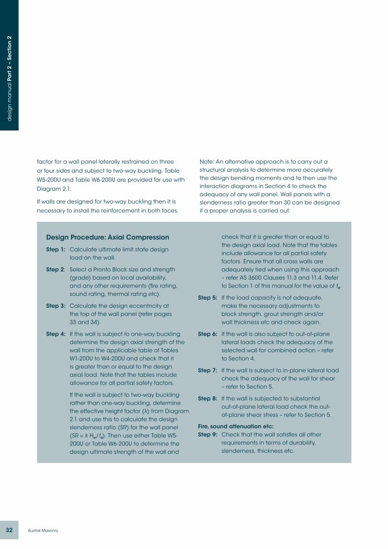
Design Procedure: Axial Compression
Step 1: Calculate ultimate limit state design load on the wall.
Step 2: Select a Pronto Block size and strength (grade) based on local availability, and any other requirements (fire rating, sound rating, thermal rating etc).
Step 3: Calculate the design eccentricity at the top of the wall panel (refer pages 33 and 34).
Step 4: If the wall is subject to one-way buckling determine the design axial strength of the wall from the applicable table of Tables W1-200U to W4-200U and check that it is greater than or equal to the design axial load. Note that the tables include allowance for all partial safety factors.
If the wall is subject to two-way buckling rather than one-way buckling, determine the effective height factor (k) from Diagram 2.1 and use this to calculate the design slenderness ratio (SR) for the wall panel (SR = k Hw/td). Then use either Table W5-200U or Table W6-200U to determine the design ultimate strength of the wall and
check that it is greater than or equal to the design axial load. Note that the tables include allowance for all partial safety factors. Ensure that all cross walls are adequately tied when using this approach – refer AS 3600 Clauses 11.3 and 11.4. Refer to Section 1 of this manual for the value of td.
Step 5: If the load capacity is not adequate, make the necessary adjustments to block strength, grout strength and/or wall thickness etc and check again.
Step 6: If the wall is also subject to out-of-plane lateral loads check the adequacy of the selected wall for combined action – refer to Section 4.
Step 7: If the wall is subject to in-plane lateral load check the adequacy of the wall for shear – refer to Section 5.
Step 8: If the wall is subjected to substantial out-of-plane lateral load check the out- of-plane shear stress – refer to Section 5.
Fire, sound attenuation etc:Step 9: Check that the wall satisfies all other
requirements in terms of durability, slenderness, thickness etc.
factor for a wall panel laterally restrained on three
or four sides and subject to two-way buckling. Table
W5-200U and Table W6-200U are provided for use with
Diagram 2.1.
If walls are designed for two-way buckling then it is
necessary to install the reinforcement in both faces.
Note: An alternative approach is to carry out a structural analysis to determine more accurately the design bending moments and to then use the interaction diagrams in Section 4 to check the adequacy of any wall panel. Wall panels with a slenderness ratio greater than 30 can be designed if a proper analysis is carried out.

33Pronto Block Walls | Technical Manual
de
sig
n m
an
ua
l Pa
rt 2
– S
ec
tion
2
Calculation of effective eccentricity when designing for compression using simplified method:
AS 3600 Clause 11.5.2 permits the calculation of eccentricity of applied vertical loads at the top of walls as follows:
– The minimum eccentricity shall be 0.05td
– The vertical load transmitted to a wall by a discontinuous concrete floor or roof shall be assumed to act at one third of the bearing depth measured from the span face of the wall.
– Where there is an insitu concrete floor or roof
continuous over the wall, the load shall be
assumed to act at the center of the wall.
– It is recommended by the author that if the
continuous slab has different spans on each
side of the wall then each side of the floor or roof
shall be taken as being individually supported on
half the total bearing area.
It also permits the assumption that the eccentricity of
aggregated load from all floors above the floor at the
top of the wall being designed is zero.
Examples of how to calculate the effective eccentricity using the above:

34 Austral Masonry
de
sig
n m
an
ua
l Pa
rt 2
– S
ec
tion
2
Examples of how to calculate the effective eccentricity using the above:

35Pronto Block Walls | Technical Manual
de
sig
n m
an
ua
l Pa
rt 2
– S
ec
tion
2
TABLE W1-200U Effective height factor k = 0.75
15MPa Blocks 20MPa Core fill (ƒ’c = 20MPa) Rotational restraint both ends of wall panel
200 Pronto Block (unchamfered)
Hw Hwe SR ea
Design ultimate strength ØNu (kN/m)
e = 8.7mm e = 10mm e = 15mm e = 20mm e = 25mm e = 33mm
2000 1500 8.6 5.2 827 819 787 754 722 670
2200 1650 9.5 6.3 816 807 775 742 710 658
2400 1800 10.3 7.4 803 794 762 730 697 645
2600 1950 11.2 8.7 789 780 748 716 683 631
2800 2100 12.1 10.1 774 765 733 701 668 616
3000 2250 12.9 11.6 758 749 717 684 652 600
3200 2400 13.8 13.2 740 732 699 667 635 583
3400 2550 14.7 14.9 722 713 681 649 616 564
3600 2700 15.5 16.8 702 694 661 629 597 545
3800 2850 16.4 18.7 682 673 641 608 576 524
4000 3000 17.2 20.7 660 651 619 587 554 502
4200 3150 18.1 22.8 637 628 596 564 531 479
4400 3300 19.0 25.0 613 604 572 540 507 455
4600 3450 19.8 27.4 588 579 547 514 482 430
4800 3600 20.7 29.8 561 553 521 488 456 404
5000 3750 21.6 32.3 534 526 493 461 428 377
5200 3900 22.4 35.0 506 497 465 432 400 348
5400 4050 23.3 37.7 476 468 435 403 370 319
5600 4200 24.1 40.6 445 437 404 372 340 288
5800 4350 25.0 43.5 413 405 373 340 308 256
6000 4500 25.9 46.6 380 372 340 307 275 223
6200 4650 26.7 49.7 346 338 306 273 241 189
6400 4800 27.6 53.0 311 303 270 238 206 154
6600 4950 28.4 56.3 275 266 234 202 169 117
6800 5100 29.3 59.8 237 229 197 164 132 80
NotesUse this table to determine the design axial strength (ØNu) for a wall of any clear height that does not exceed the slenderness ratio limit set in AS 3600:2009. Note that the slenderness ratio limit for walls is 30 (refer AS 3600 Clause 11.5) and this table is curtailed at that slenderness ratio.
8.7mm is the minimum design eccentricity for any unchamfered 200 Pronto Block wall.
Linear interpolation may be used for any intermediate values of design eccentricity.
When using this table ensure that the ends of the wall panel (the top and bottom end) are restrained rotationally. Insitu slabs at top and bottom are considered to provide rotational restraint.
The tabulated values of ØNu account for the reduction in axial load resulting from the additional eccentricity (ea) due to slenderness effects. The value of ea for each wall height is tabulated.
A capacity reduction factor (Ø) of 0.6 has been used when calculating the tabulated strengths.

36 Austral Masonry
de
sig
n m
an
ua
l Pa
rt 2
– S
ec
tion
2
TABLE W2-200U Effective height factor k = 0.75
20MPa Blocks 20MPa Core fill (ƒ’c = 20MPa) Rotational restraint both ends of wall panel
200 Pronto Block (unchamfered)
Hw Hwe SR ea
Design ultimate strength ØNu (kN/m)
e = 8.7mm e = 10mm e = 15mm e = 20mm e = 25mm e = 33mm
2000 1500 8.6 5.2 1103 1092 1049 1006 962 893
2200 1650 9.5 6.3 1088 1076 1033 990 947 878
2400 1800 10.3 7.4 1070 1059 1016 973 930 860
2600 1950 11.2 8.7 1052 1041 997 954 911 842
2800 2100 12.1 10.1 1032 1020 977 934 891 822
3000 2250 12.9 11.6 1010 999 956 912 869 800
3200 2400 13.8 13.2 987 976 933 889 846 777
3400 2550 14.7 14.9 962 951 908 865 822 752
3600 2700 15.5 16.8 936 925 882 839 795 726
3800 2850 16.4 18.7 909 898 854 811 768 699
4000 3000 17.2 20.7 880 868 825 782 739 670
4200 3150 18.1 22.8 849 838 795 752 708 639
4400 3300 19.0 25.0 817 806 763 720 676 607
4600 3450 19.8 27.4 784 772 729 686 643 574
4800 3600 20.7 29.8 749 737 694 651 608 539
5000 3750 21.6 32.3 712 701 658 614 571 502
5200 3900 22.4 35.0 674 663 620 576 533 464
5400 4050 23.3 37.7 635 623 580 537 494 425
5600 4200 24.1 40.6 594 582 539 496 453 384
5800 4350 25.0 43.5 551 540 497 454 410 341
6000 4500 25.9 46.6 507 496 453 410 366 297
6200 4650 26.7 49.7 462 451 407 364 321 252
6400 4800 27.6 53.0 415 404 360 317 274 205
6600 4950 28.4 56.3 367 355 312 269 226 157
6800 5100 29.3 59.8 317 305 262 219 176 107
NotesUse this table to determine the design axial strength (ØNu) for a wall of any clear height that does not exceed the slenderness ratio limit set in AS 3600:2009. Note that the slenderness ratio limit for walls is 30 (refer AS 3600 Clause 11.5) and this table is curtailed at that slenderness ratio.
8.7mm is the minimum design eccentricity for any unchamfered 200 Pronto Block wall.
Linear interpolation may be used for any intermediate values of design eccentricity.
When using this table ensure that the ends of the wall panel (the top and bottom end) are restrained rotationally. Insitu slabs at top and bottom are considered to provide rotational restraint.
The tabulated values of ØNu account for the reduction in axial load resulting from the additional eccentricity (ea) due to slenderness effects. The value of ea for each wall height is tabulated.
A capacity reduction factor (Ø) of 0.6 has been used when calculating the tabulated strengths.

37Pronto Block Walls | Technical Manual
de
sig
n m
an
ua
l Pa
rt 2
– S
ec
tion
2
TABLE W3-200U Effective height factor k = 1.0
15MPa Blocks 20MPa Core fill (ƒ’c = 20MPa) No rotational restraint both ends of wall panel (just lateral restraint)
200 Pronto Block (unchamfered)
Hw Hwe SR ea
Design ultimate strength ØNu (kN/m)
e = 8.7mm e = 10mm e = 15mm e = 20mm e = 20mm e = 29mm
2000 2000 11.5 9.2 784 775 743 711 678 626
2200 2200 12.6 11.1 763 755 722 690 657 606
2400 2400 13.8 13.2 740 732 699 667 635 583
2600 2600 14.9 15.5 715 707 675 642 610 558
2800 2800 16.1 18.0 689 680 648 615 583 531
3000 3000 17.2 20.7 660 651 619 587 554 502
3200 3200 18.4 23.5 629 621 588 556 523 472
3400 3400 19.5 26.6 596 588 555 523 491 439
3600 3600 20.7 29.8 561 553 521 488 456 404
3800 3800 21.8 33.2 525 516 484 451 419 367
4000 4000 23.0 36.8 486 478 445 413 380 329
4200 4200 24.1 40.6 445 437 404 372 340 288
4400 4400 25.3 44.5 403 394 362 329 297 245
4600 4600 26.4 48.6 358 349 317 285 252 200
4800 4800 27.6 53.0 311 303 270 238 206 154
5000 5000 28.7 57.5 263 254 222 189 157 105
5200 5200 29.9 62.2 212 203 171 139 106 54
Notes:Use this table to determine the design axial strength (ØNu) for a wall of any clear height that does not exceed the slenderness ratio limit set in AS 3600:2009. Note that the slenderness ratio limit for walls is 30 (refer AS 3600 Clause 11.5) and this table is curtailed at that slenderness ratio.
8.7mm is the minimum design eccentricity for any unchamfered 200 Pronto Block wall.
Linear interpolation may be used for any intermediate values of design eccentricity.
This table is for walls in which the ends are only restrained laterally and not rotationally. Ensure always that there is adequate connection between the walls and the roof or floor slabs to provide such restraint (refer AS 3600 Clause 11.3)
The tabulated values of ØNu account for the reduction in axial load resulting from the additional eccentricity (ea) due to slenderness effects. The value of ea for each wall height is tabulated.
A capacity reduction factor (Ø) of 0.6 has been used when calculating the tabulated strengths.

38 Austral Masonry
de
sig
n m
an
ua
l Pa
rt 2
– S
ec
tion
2
TABLE W4-200U Effective height factor k = 1.0
20MPa Blocks 20MPa Core fill (ƒ’c = 20MPa) No rotational restraint both ends of wall panel (just lateral restraint)
200 Pronto Block (unchamfered)
Hw Hwe SR ea
Design ultimate strength ØNu (kN/m)
e = 8.7mm e = 10mm e = 15mm e = 20mm e = 25mm e = 33mm
2000 2000 11.5 9.2 1045 1034 991 948 904 835
2200 2200 12.6 11.1 1017 1006 963 920 877 807
2400 2400 13.8 13.2 987 976 933 889 846 777
2600 2600 14.9 15.5 954 943 899 856 813 744
2800 2800 16.1 18.0 918 907 864 820 777 708
3000 3000 17.2 20.7 880 868 825 782 739 670
3200 3200 18.4 23.5 839 827 784 741 698 629
3400 3400 19.5 26.6 795 784 741 697 654 585
3600 3600 20.7 29.8 749 737 694 651 608 539
3800 3800 21.8 33.2 700 688 645 602 559 490
4000 4000 23.0 36.8 648 637 594 550 507 438
4200 4200 24.1 40.6 594 582 539 496 453 384
4400 4400 25.3 44.5 537 526 482 439 396 327
4600 4600 26.4 48.6 477 466 423 380 336 267
4800 4800 27.6 53.0 415 404 360 317 274 205
5000 5000 28.7 57.5 350 339 296 252 209 140
5200 5200 29.9 62.2 283 271 228 185 142 73
NotesUse this table to determine the design axial strength (ØNu) for a wall of any clear height that does not exceed the slenderness ratio limit set in AS 3600:2009. Note that the slenderness ratio limit for walls is 30 (refer AS 3600 Clause 11.5) and this table is curtailed at that slenderness ratio.
8.7mm is the minimum design eccentricity for any unchamfered 200 Pronto Block wall.
Linear interpolation may be used for any intermediate values of design eccentricity.
This table is for walls in which the ends are only restrained laterally and not rotationally. Ensure always that there is adequate connection between the walls and the roof or floor slabs to provide such restraint (refer AS 3600 Clause 11.3)
The tabulated values of ØNu account for the reduction in axial load resulting from the additional eccentricity (ea) due to slenderness effects. The value of ea for each wall height is tabulated.
A capacity reduction factor (Ø) of 0.6 has been used when calculating the tabulated strengths.

39Pronto Block Walls | Technical Manual
de
sig
n m
an
ua
l Pa
rt 2
– S
ec
tion
2
DIAGRAM 2.1:
Refer AS 3600 Clauses 11.4b) and 11.4c)
0
0.1
0.2
0.3
0.4
0.5
0.6
0.7
0.8
0.9
1
0 0.5 1 1.5 2.5 3 3.5 4 4.52
Restraint three sides only
Restraint four sides
40 Austral Masonry
de
sig
n m
an
ua
l Pa
rt 2
– S
ec
tion
2
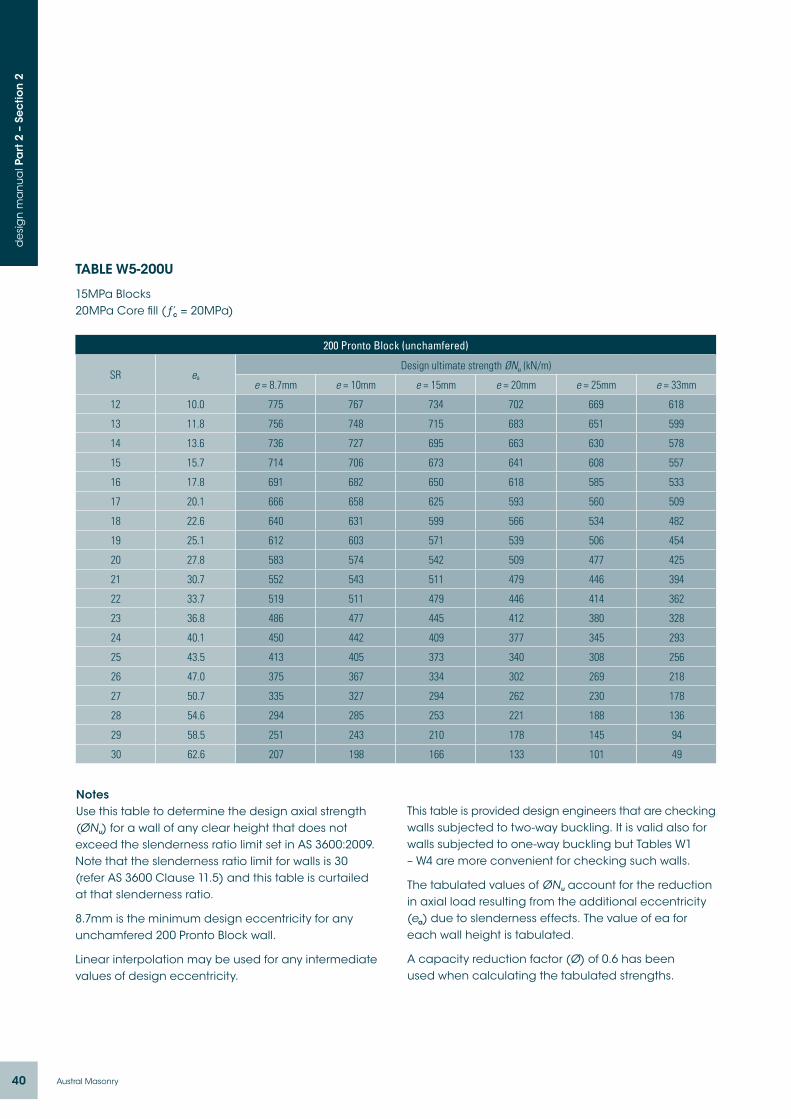
TABLE W5-200U
15MPa Blocks 20MPa Core fill (ƒ’c = 20MPa)
200 Pronto Block (unchamfered)
SR ea
Design ultimate strength ØNu (kN/m)
e = 8.7mm e = 10mm e = 15mm e = 20mm e = 25mm e = 33mm
12 10.0 775 767 734 702 669 618
13 11.8 756 748 715 683 651 599
14 13.6 736 727 695 663 630 578
15 15.7 714 706 673 641 608 557
16 17.8 691 682 650 618 585 533
17 20.1 666 658 625 593 560 509
18 22.6 640 631 599 566 534 482
19 25.1 612 603 571 539 506 454
20 27.8 583 574 542 509 477 425
21 30.7 552 543 511 479 446 394
22 33.7 519 511 479 446 414 362
23 36.8 486 477 445 412 380 328
24 40.1 450 442 409 377 345 293
25 43.5 413 405 373 340 308 256
26 47.0 375 367 334 302 269 218
27 50.7 335 327 294 262 230 178
28 54.6 294 285 253 221 188 136
29 58.5 251 243 210 178 145 94
30 62.6 207 198 166 133 101 49
NotesUse this table to determine the design axial strength (ØNu) for a wall of any clear height that does not exceed the slenderness ratio limit set in AS 3600:2009. Note that the slenderness ratio limit for walls is 30 (refer AS 3600 Clause 11.5) and this table is curtailed at that slenderness ratio.
8.7mm is the minimum design eccentricity for any unchamfered 200 Pronto Block wall.
Linear interpolation may be used for any intermediate values of design eccentricity.
This table is provided design engineers that are checking walls subjected to two-way buckling. It is valid also for walls subjected to one-way buckling but Tables W1 – W4 are more convenient for checking such walls.
The tabulated values of ØNu account for the reduction in axial load resulting from the additional eccentricity (ea) due to slenderness effects. The value of ea for each wall height is tabulated.
A capacity reduction factor (Ø) of 0.6 has been used when calculating the tabulated strengths.

41Pronto Block Walls | Technical Manual
de
sig
n m
an
ua
l Pa
rt 2
– S
ec
tion
2
TABLE W6-200U
20MPa Blocks 20MPa Core fill (ƒ’c = 20MPa)
200 Pronto Block (unchamfered)
SR ea
Design ultimate strength ØNu (kN/m)
e = 8.7mm e = 10mm e = 15mm e = 20mm e = 25mm e = 33mm
12 10.0 1033 1022 979 936 892 823
13 11.8 1008 997 954 911 867 798
14 13.6 981 970 927 884 840 771
15 15.7 952 941 898 854 811 742
16 17.8 921 910 867 823 780 711
17 20.1 888 877 834 790 747 678
18 22.6 853 842 798 755 712 643
19 25.1 816 805 761 718 675 606
20 27.8 777 766 722 679 636 567
21 30.7 736 724 681 638 595 526
22 33.7 693 681 638 595 552 483
23 36.8 647 636 593 550 507 437
24 40.1 600 589 546 503 460 390
25 43.5 551 540 497 454 410 341
26 47.0 500 489 446 402 359 290
27 50.7 447 436 393 349 306 237
28 54.6 392 381 337 294 251 182
29 58.5 335 324 280 237 194 125
30 62.6 276 264 221 178 135 66
NotesUse this table to determine the design axial strength (ØNu) for a wall of any clear height that does not exceed the slenderness ratio limit set in AS 3600:2009. Note that the slenderness ratio limit for walls is 30 (refer as 3600 Clause 11.5) and this table is curtailed at that slenderness ratio.
8.7mm is the minimum design eccentricity for any unchamfered 200 Pronto Block wall.
Linear interpolation may be used for any intermediate values of design eccentricity.
This table is provided design engineers that are checking walls subjected to two-way buckling. It is valid also for walls subjected to one-way buckling but Tables W1 – W4 are more convenient for checking such walls.
The tabulated values of ØNu account for the reduction in axial load resulting from the additional eccentricity (ea) due to slenderness effects. The value of ea for each wall height is tabulated.
A capacity reduction factor (Ø) of 0.6 has been used when calculating the tabulated strengths.

42 Austral Masonry
section 3.Design of walls in bending
de
sig
n m
an
ua
l Pa
rt 2
– S
ec
tion
3
This section is for the design of walls subjected to out-of-plane lateral loads only, however it can also be used for the design of walls subjected to only small axial compression loads where the stress at mid-height due to bending and compression does not exceed the lesser of 0.03ƒ’c and 2MPa (Refer AS 3600 Clause 11.1b))
Bar position H2 for load on side B Bar position H2 for load on side A
Bar position V1 for load on side B
A
A B
B
H2 H2
H2 H2
Bar position V1 for load on side A
Reinforcing bar positions V1 and H2for 200 unchamfered Pronto Block
Reinforcing bar positionsThe location of all reinforcement in Pronto Block walls is controlled by the notches in the connectors that support the horizontal bars. The 200 mortarless connectors have four notches, and the bar positions are described as V1, V2, H1 and H2 as shown in the following diagrams. Positions V1 and H1 are located furthest from the neutral axis, while positions V2 and H2 are located closest to the neutral axis. These positions are referred to in the moment capacity tables 3.1, 3.2 and 3.3.
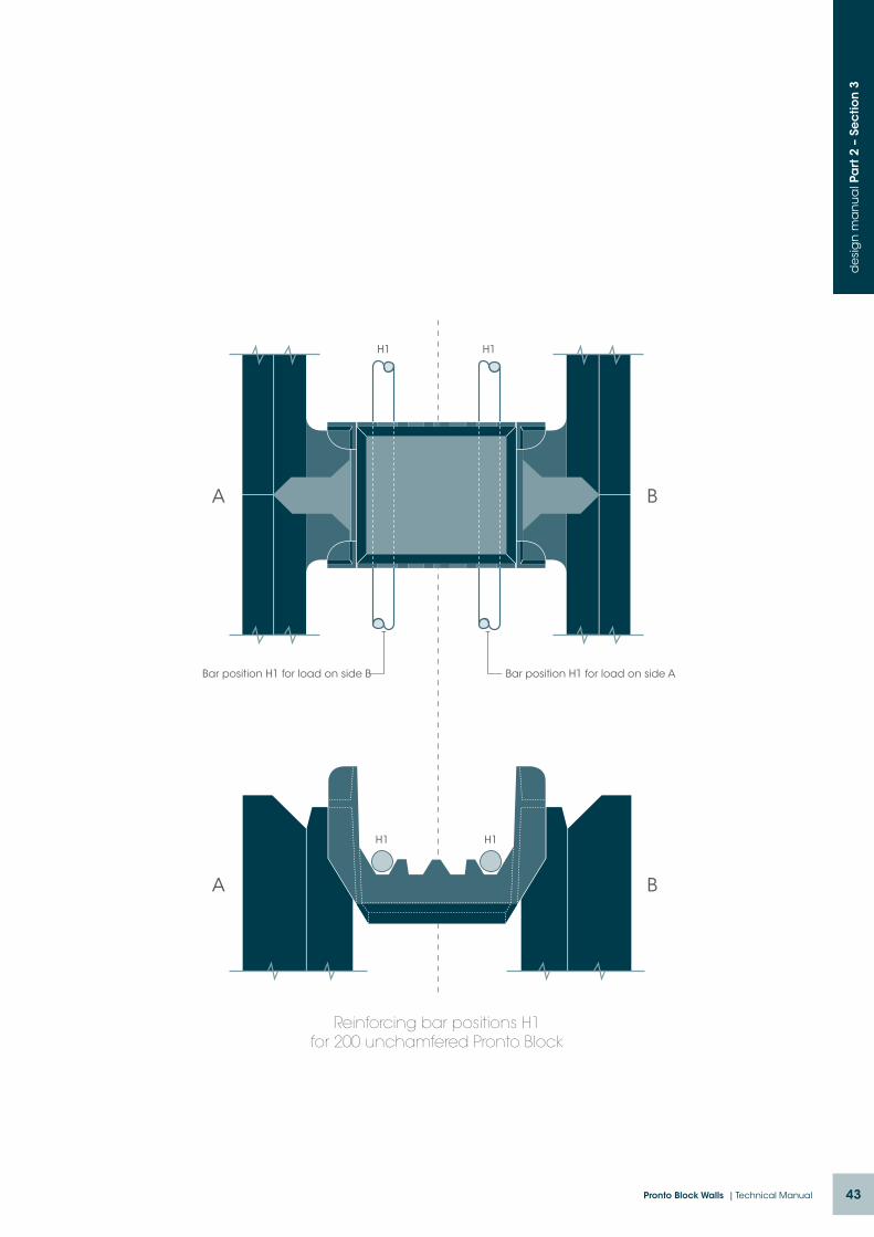
43Pronto Block Walls | Technical Manual
de
sig
n m
an
ua
l Pa
rt 2
– S
ec
tion
3
A B
H1 H1
Bar position H1 for load on side B
A B
H1 H1
Bar position H1 for load on side A
Reinforcing bar positions H1for 200 unchamfered Pronto Block
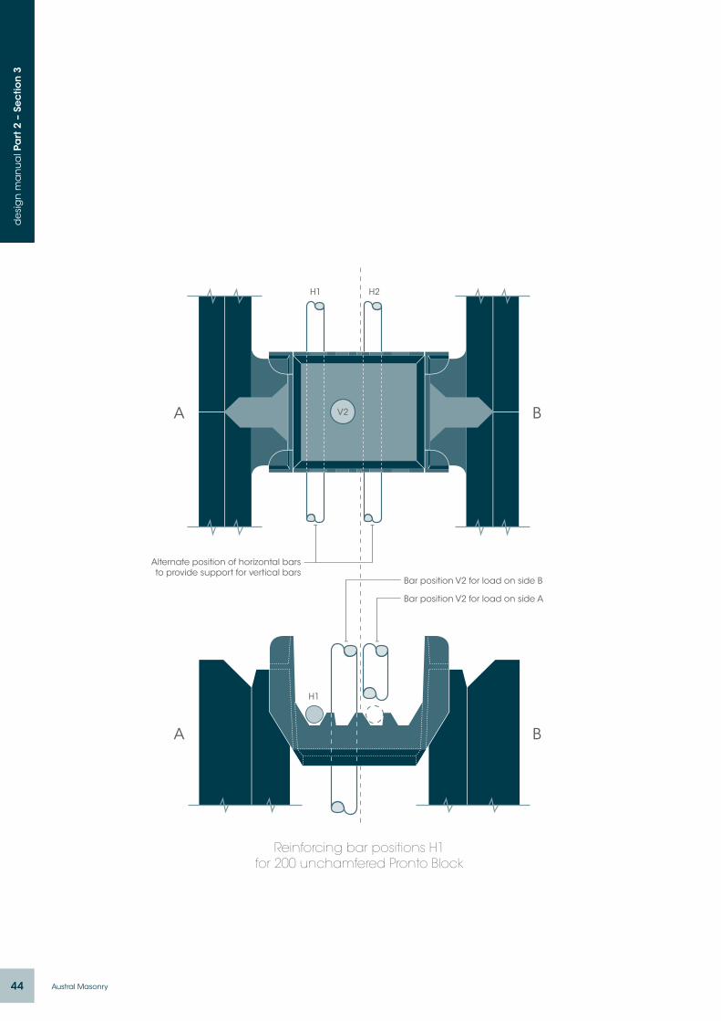
44 Austral Masonry
de
sig
n m
an
ua
l Pa
rt 2
– S
ec
tion
3
A B
H1 H2
Alternate position of horizontal barsto provide support for vertical bars
A B
H1
Bar position V2 for load on side B
Bar position V2 for load on side A
Reinforcing bar positions H1for 200 unchamfered Pronto Block
V2

45Pronto Block Walls | Technical Manual
de
sig
n m
an
ua
l Pa
rt 2
– S
ec
tion
3
Design Procedure: Bending
Out-of-plane bending (walls):Step 1: Calculate ultimate limit state design
bending moment.
Step 2: Select a Pronto Block size and strength (grade) based on local availability and any other requirements (fire rating, sound rating, thermal rating etc).
Step 3: Using Table 3.1 determine the reinforcement size, spacing and location that will give a bending moment capacity equal to or greater than the design bending moment.
Ensure the bar positions (vertical and/or horizontal) are specified on the drawings. Note that when the vertical
bars are required to be in any of the four possible locations it is necessary to specify the appropriate horizontal bar positions. The horizontal bars are used to guide the vertical bars into their correct location and to support them in that location throughout the height of the wall – refer to the sections on pages 42 – 44.
In-plane bending (beams):Step 1: Calculate ultimate limit state design
bending moment.
Step 2: Using Table 3.2 or 3.3 determine the reinforcement requirement noting that these tables can be used for checking both the positive and the negative bending moment reinforcement requirements.

46 Austral Masonry
de
sig
n m
an
ua
l Pa
rt 2
– S
ec
tion
3
Bending moment capacities for Pronto Block walls subject to out-of-plane loads
TABLE 3.1:
200 Pronto Block (unchamfered)
Block Grade & Reinforcement (ƒy = 500MPa)
As mm2/m
Bending moment capacity ØMu (kNm/m)
Vertical bending Horizontal bending
Asd mm2/m
bars in position V1
d = 112
Asd mm2/m
bars in position V2
d = 93
Asd mm2/m
bars in position H1
d = 114
Asd mm2/m
bars in position H2
d = 96
Grade 15 blocks 20MPa Grout
N12-200 550 550 17.0 550 13.8 550 17.3 550 14.3
N12-400 275 275 8.9 275 7.3 275 9.0 275 7.5
N12-600 183 183 6.0 183 4.9 183 6.1 183 5.1
N16-200 1000 1000 28.6 1000 22.9
N16-400 500 500 15.6 500 12.7
N16-600 333 333 10.6 333 8.7
Grade 20 blocks 20MPa Grout
N12-200 550 550 17.3 550 14.2 550 17.7 550 14.7
N12-400 275 275 9.0 275 7.4 275 9.1 275 7.6
N12-600 183 183 6.0 183 5.0 183 6.1 183 5.1
N16-200 1000 1000 29.9 1000 24.2
N16-400 500 500 15.9 500 13.0
N16-600 333 333 10.8 333 8.9
NotesAll reinforcement to be Grade 500 deformed bars.
The tabulated values have been calculated in accordance with AS 3600 Clause 8.1.
As is the area of tensile reinforcement installed in the wall.
Asd is the area of tensile reinforcement used for design of the section.
The tabulated bending moment capacities include all of the capacity reduction factor Ø=0.6.
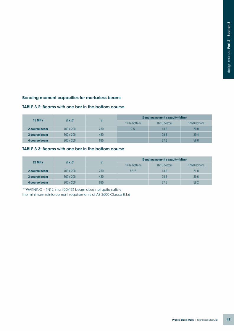
47Pronto Block Walls | Technical Manual
de
sig
n m
an
ua
l Pa
rt 2
– S
ec
tion
3
Bending moment capacities for mortarless beams
TABLE 3.2: Beams with one bar in the bottom course
15 MPa D x B dBending moment capacity (kNm)
1N12 bottom 1N16 bottom 1N20 bottom
2 course beam 400 x 200 230 7.5 13.6 20.8
3 course beam 600 x 200 430 25.6 39.4
4 course beam 800 x 200 630 37.6 58.0
TABLE 3.3: Beams with one bar in the bottom course
20 MPa D x B dBending moment capacity (kNm)
1N12 bottom 1N16 bottom 1N20 bottom
2 course beam 400 x 200 230 7.5** 13.6 21.0
3 course beam 600 x 200 430 25.6 39.6
4 course beam 800 x 200 630 37.6 58.2
**WARNING – 1N12 in a 400x174 beam does not quite satisfy the minimum reinforcement requirements of AS 3600 Clause 8.1.6

48 Austral Masonry
section 4.design of pronto block walls for axial compression combined with out-of-plane bending
de
sig
n m
an
ua
l Pa
rt 2
– S
ec
tion
4
Section 2 deals with the design of walls for axial compression loads where the axial load capacity is determined in accordance with the simplified design method outlined in AS 3600 Clause 11.5. The tabulated values in Section 2 take into account both the design eccentricity of the axial load and the additional eccentricity resulting from slenderness.
Walls can also be subjected to out of plane lateral loads however that may increase the design bending moments. While axial compression loads can increase the moment capacity of a wall it is important to check that the increased design compressive stress in the extreme fibre of the concrete section does not exceed the permissible stress when the wall is subjected to the combined action.
In this Section of the design manual interaction diagrams are provided for the purpose of checking combined bending and compression. These diagrams
can be used to determine whether or not a critical section is over stressed due to the combined action.
There is no provision in AS 3600 for checking combined bending and compression using the simplified design method. The simplified design method takes into account the design bending moment due to eccentricity of the applied load at the top of the wall panel and it also takes into account the additional design bending moment due to slenderness effects but there is no provision for adding in any additional bending moment resulting from out-of-plane lateral loads.
When using the interaction diagrams it is very important to remember that the minimum design bending moment at any cross section is N* times 0.05td, i.e. the bending moment that corresponds to a minimum 5% design eccentricity.
The reinforcement requirements for the wall panel can be determined using the interaction diagrams.
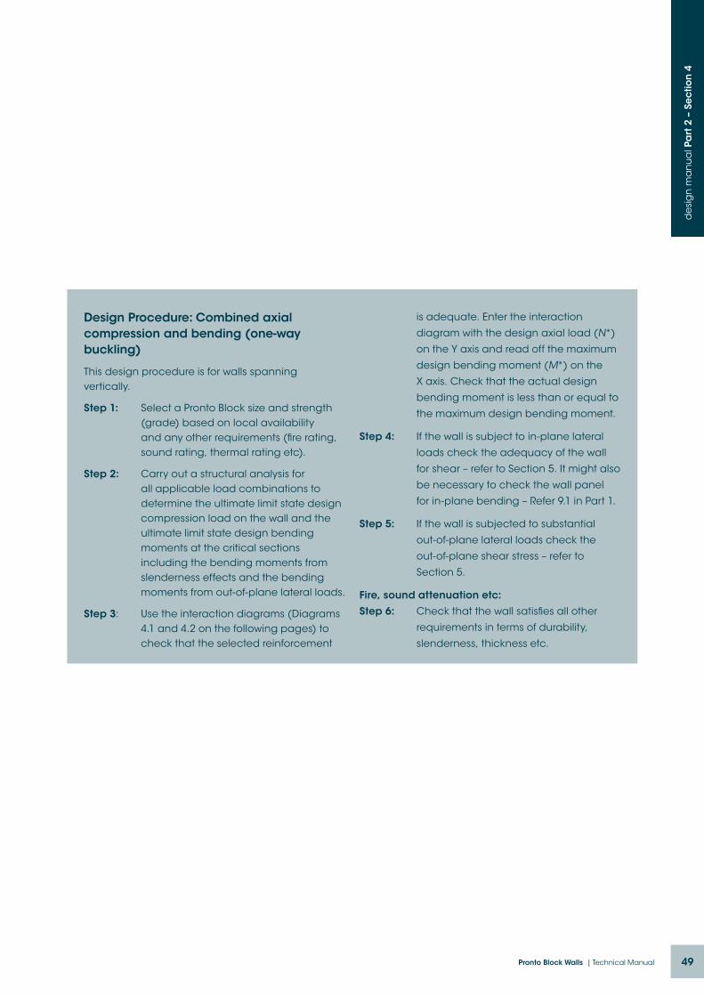
49Pronto Block Walls | Technical Manual
de
sig
n m
an
ua
l Pa
rt 2
– S
ec
tion
4
Design Procedure: Combined axial compression and bending (one-way buckling)
This design procedure is for walls spanning vertically.
Step 1: Select a Pronto Block size and strength (grade) based on local availability and any other requirements (fire rating, sound rating, thermal rating etc).
Step 2: Carry out a structural analysis for all applicable load combinations to determine the ultimate limit state design compression load on the wall and the ultimate limit state design bending moments at the critical sections including the bending moments from slenderness effects and the bending moments from out-of-plane lateral loads.
Step 3: Use the interaction diagrams (Diagrams 4.1 and 4.2 on the following pages) to check that the selected reinforcement
is adequate. Enter the interaction
diagram with the design axial load (N*)
on the Y axis and read off the maximum
design bending moment (M*) on the
X axis. Check that the actual design
bending moment is less than or equal to
the maximum design bending moment.
Step 4: If the wall is subject to in-plane lateral
loads check the adequacy of the wall
for shear – refer to Section 5. It might also
be necessary to check the wall panel
for in-plane bending – Refer 9.1 in Part 1.
Step 5: If the wall is subjected to substantial
out-of-plane lateral loads check the
out-of-plane shear stress – refer to
Section 5.
Fire, sound attenuation etc:
Step 6: Check that the wall satisfies all other
requirements in terms of durability,
slenderness, thickness etc.

50 Austral Masonry
de
sig
n m
an
ua
l Pa
rt 2
– S
ec
tion
4
DIAGRAM 4.1: 15MPa blocks with min. 20MPa grout
05 10 15 20 25 300
100
200
300
400
500
600
700
800
900
1000
1100
1200
1300 N12-200 in V1 position
N16-400 in V1 position
N12-300 in V1 position
N12-400 in V1 position
Note: N12-300 is achieved withN12 at 200 and 400 alternating
NotesThis interaction diagram is to be used for checking the adequacy of any critical cross section for the combined action of compression and out-of-plane bending.
A compressive stress of 0.85ƒ’c was used for the rectangular stress block when calculating the values in the above diagram. This is not compatible with the values in Tables W1-200U – W4-200U that were prepared using the simplified design method for walls in vertical compression and in which the compressive stress in the rectangular stress block was just 0.6ƒ’c.
When using this diagram use bending moments derived from a structural analysis which include t
he additional bending moments due to slenderness effects. Do not use the bending moments calculated using the simplified approach.
Always ensure that the axial compression load used
when checking for reinforcement requirements is the
minimum sustained design axial compression load.
When using the chart enter with the design axial
compression load N* and read off the maximum
design bending moment M*=ØMu.
Ensure that the vertical reinforcement is placed
in the tension face of the wall in all cases.

51Pronto Block Walls | Technical Manual
de
sig
n m
an
ua
l Pa
rt 2
– S
ec
tion
4
DIAGRAM 4.2: 20MPa blocks with min. 20MPa grout
N12-200 in V1 position
N16-400 in V1 position
N12-300 in V1 position
N12-400 in V1 position
Note: N12-300 is achieved withN12 at 200 and 400 alternating
0
100
200
300
400
500
600
700
800
900
1000
1100
1200
1300
1400
1500
1600
1700
1800
0 5 10 15 20 25 30 35 40
NotesThis interaction diagram is to be used for checking the adequacy of any critical cross section for the combined action of compression and out-of-plane bending.
A compressive stress of 0.85ƒ’c was used for the rectangular stress block when calculating the values in the above diagram. This is not compatible with the values in Tables W1-200U – W4-200U that were prepared using the simplified design method for walls in vertical compression and in which the compressive stress in the rectangular stress block was just 0.6ƒ’c.
When using this diagram use bending moments derived from a structural analysis which include
the additional bending moments due to slenderness effects. Do not use the bending moments calculated using the simplified approach.
Always ensure that the axial load used when checking
for reinforcement requirements is the minimum
sustained design axial compression load.
When using the chart enter with the design axial
compression load N* and read off the maximum
design bending moment M*=ØMu.
Ensure that the vertical reinforcement is placed
in the tension face of the wall in all cases.

52 Austral Masonry
section 5.Design of Pronto Block Walls for sheard
esi
gn
ma
nu
al P
art
2 –
Se
ctio
n 5
Load-bearing walls are mostly designed to carry axial compression loads, however in many load bearing wall structures they are also designed to carry the lateral loads arising from wind, earthquake etc, i.e. they are designed as shear walls. Diagrams 5.1 and 5.2 in this Section provide a means of readily checking the capacity of a wall to take in-plane shear. The design strength of the wall is the sum of the values obtained from the two Diagrams. It is necessary to use the correct reinforcement area when using Diagram 5.2 and this is explained in the notes below the Diagram.
Load-bearing walls can also be subjected to out of plane lateral loads, a typical example being a
retaining wall designed to carry earth pressure loads. These walls may need to be checked for transverse shear loads at critical sections and Diagrams 5.3 and 5.4 in this Section is provided to make this task very easy. It can readily be seen in the Diagram that the transverse shear capacity increases as the axial load N* increases.
Reinforced Pronto Block is also often used as lintel beams and the like to span across openings. These members need to be designed for shear the same as any reinforced concrete beam and Tables 5.1 and 5.2 in this Section make it very easy to check the shear capacity of Pronto Block beams.
Design Procedure: Shear
In-Plane Shear (Shear Walls):Step 1: Calculate ultimate limit state design
shear force on the wall panel.
Step 2: Determine the shear strength of the wall panel (excluding the contribution from reinforcement) using Diagram 5.1. Note that the value obtained from Diagram 5.1 is the shear capacity per linear metre of the wall panel length, so simply multiply the value obtained from the Diagram by the length in metres to obtain the total shear capacity.
Step 3: Determine the contribution to shear strength of the wall reinforcement using Diagram 5.2.
Again note that this gives the shear strength per linear metre and note that all reinforcement used when determining a value from this Diagram must be anchored beyond the critical section.
In-Plane Shear (Beams):Step 1: Calculate ultimate limit state design
shear force on the beam at the critical
section.
Step 2: Use Table 5.2 to determine whether
the beam has adequate shear
strength without the need for shear
reinforcement. If not then proceed
to Step 3.
Step 3: Use Table 5.2 to determine whether the
beam has adequate shear strength with
single leg R10 shear reinforcement. If not
then select a deeper beam or use an
alternative beam.
Out-Of-Plane Shear:Step 1: Calculate ultimate limit state design
shear force on the wall.
Step 2: Use Diagram 5.3 or 5.4 to determine the
shear capacity of the wall and check
that this is equal to or greater than the
design shear force.

53Pronto Block Walls | Technical Manual
de
sig
n m
an
ua
l Pa
rt 2
– S
ec
tion
5
DIAGRAM 5.1 - In-plane shear strength of Pronto Block shear walls excluding contribution of reinforcement
NotesThe shear strengths given in the above Diagram are kN per linear metre of wall length.
Critical section for shear is the lesser of 0.5Lw and 0.5Hw from the base of the wall (AS 3600 Clause 11.6.1).
This diagram takes no account of the contribution of the reinforcement to the shear strength.
For the contribution of reinforcement to shear strength refer Diagram 5.2.
A value of Ø =0.7 has been used in the calculations.
010
20
30
40
50
60
70
80
90
100
110
120
130
140
150
160
170
180
190
200
210
220
230
240
250
260
270
280
290
0 0.2 0.4 0.6 0.8 1 1.2 1.4 1.6 1.8 2 2.2 2.4 2.6 2.8
ƒ’c = 15MPa
ƒ’c = 20MPa

54 Austral Masonry
de
sig
n m
an
ua
l Pa
rt 2
– S
ec
tion
5
DIAGRAM 5.2: Contribution of reinforcement to in-plane shear strength of Pronto Block shear walls
NotesThe shear strengths given in the above Diagram are kN per linear metre of wall length.
As is the cross sectional area of reinforcement per metre of wall length or wall height:
If Hw / Lw ≤1 use the lesser As of the vertical and the horizontal reinforcement.
If Hw / Lw > 1 use the As of the horizontal reinforcement.
Critical section for shear is the lesser of 0.5Lw and 0.5Hw from the base of the wall (AS 3600 Clause 11.6.1).
This diagram takes no account of the contribution of the concrete to the shear strength.
For the contribution of concrete to shear strength refer Diagram 5.1.
A value of Ø =0.7 has been used in the calculations.
0
10
20
30
40
50
60
70
80
90
100
110
120
130
140
150
160
170
0 50 100 150 200 250 300 350 400 450 500 550
reinforcement fsy – 500MPa
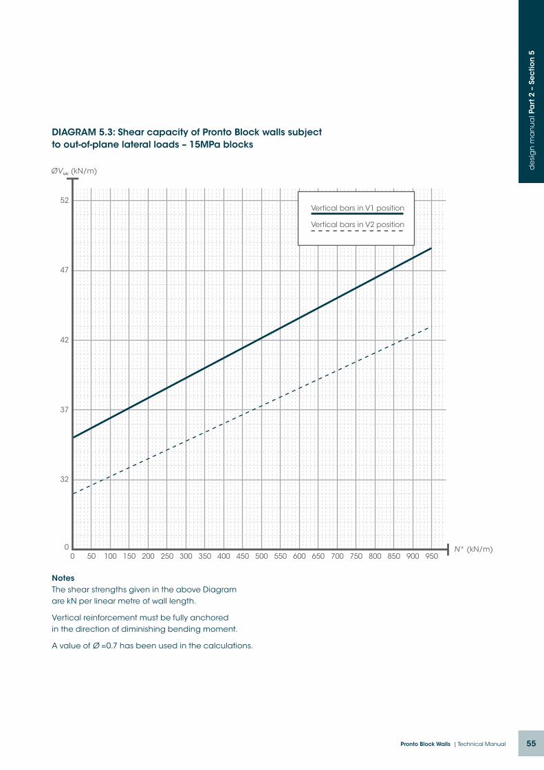
55Pronto Block Walls | Technical Manual
de
sig
n m
an
ua
l Pa
rt 2
– S
ec
tion
5
DIAGRAM 5.3: Shear capacity of Pronto Block walls subject to out-of-plane lateral loads – 15MPa blocks
NotesThe shear strengths given in the above Diagram are kN per linear metre of wall length.
Vertical reinforcement must be fully anchored in the direction of diminishing bending moment.
A value of Ø =0.7 has been used in the calculations.
0
32
37
42
47
52
0 50 100 150 200 250 300 350 400 450 500 550 600 650 700 750 800 850 900 950
Vertical bars in V1 position
Vertical bars in V2 position
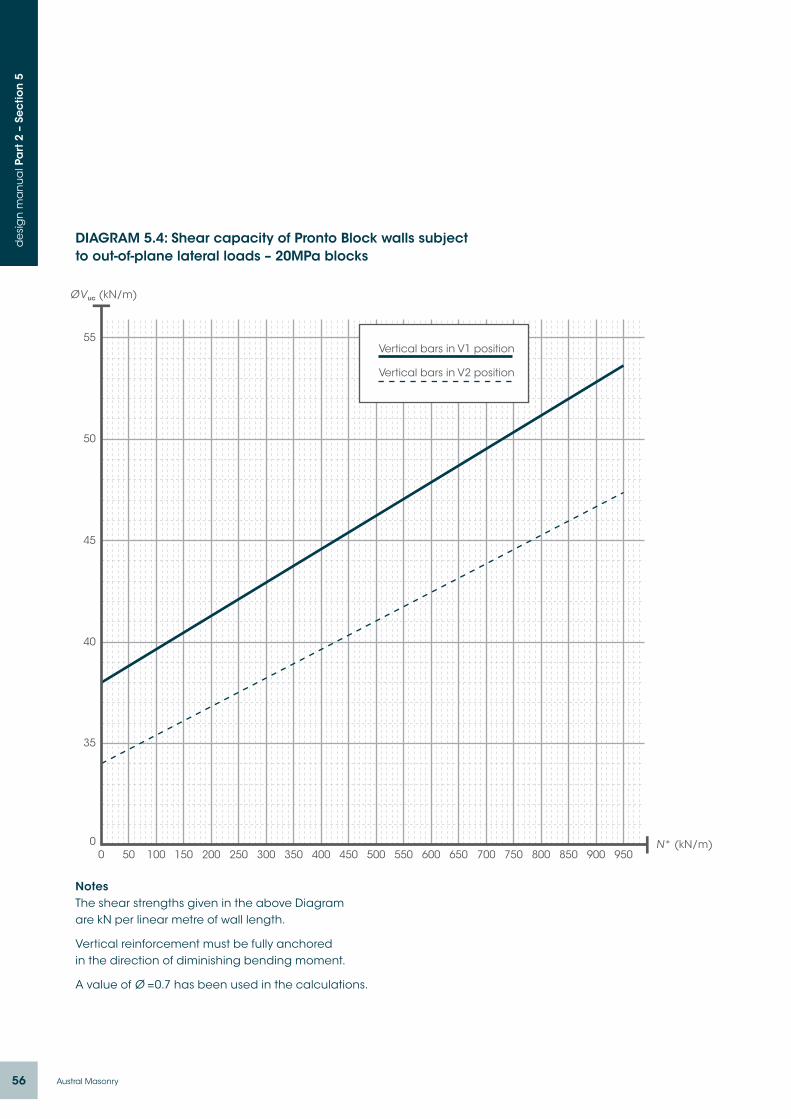
56 Austral Masonry
de
sig
n m
an
ua
l Pa
rt 2
– S
ec
tion
5
DIAGRAM 5.4: Shear capacity of Pronto Block walls subject to out-of-plane lateral loads – 20MPa blocks
NotesThe shear strengths given in the above Diagram are kN per linear metre of wall length.
Vertical reinforcement must be fully anchored in the direction of diminishing bending moment.
A value of Ø =0.7 has been used in the calculations.
0
35
40
45
50
55
0 50 100 150 200 250 300 350 400 450 500 550 600 650 700 750 800 850 900 950
Vertical bars in V1 position
Vertical bars in V2 position

57Pronto Block Walls | Technical Manual
de
sig
n m
an
ua
l Pa
rt 2
– S
ec
tion
5
TABLE 5.1: Shear capacity of 200 Pronto Block beams without shear reinforcement
Shear reinforcement: nil
Dimensions D x B
Effective Depth d
Maximum Vu without shear reinforcement (kN)
1N12 bottom 1N16 bottom 1N20 bottom
2 course beam 15MPa blocks
400 x 200 235 10.8 13.2 15.3
2 course beam 20MPa blocks
400 x 200 235 11.9 14.5 16.8
3 course beam 15 MPa blocks
600 x 200 435 16.3 19.9 23.0
3 course beam 20 MPa blocks
600 x 200 435 17.9 21.9 25.3
4 course beam 15 MPa blocks
800 x 200 635 29.6
4 course beam 20 MPa blocks
800 x 200 635 32.6
TABLE 5.2: Shear capacity of 200 Pronto Block beams with shear reinforcement
Shear reinforcement: R10-200 single leg
Dimensions D x B
Effective Depth d
Maximum Vu with R10-200 shear reinforcement (kN)
1N12 bottom 1N16 bottom 1N20 bottom
2 course beam 15MPa blocks
400 x 200 235 10.8 13.2 15.3
2 course beam 20MPa blocks
400 x 200 235 11.9 14.5 16.8
3 course beam 15 MPa blocks
600 x 200 435 46.8 50.4 53.5
3 course beam 20 MPa blocks
600 x 200 435 48.4 52.4 55.6
4 course beam 15 MPa blocks
800 x 200 635 74.1
4 course beam 20 MPa blocks
800 x 200 635 77.1


059Pronto Block Walls | Technical Manual
pronto block wallsdesign manual
Part 3AS 3600:2009
Warwick Colefax BE(Hons) DipTechEng(Struct) MIEAust CPEng RPEQ

60 Austral Masonry
de
sig
n m
an
ua
l Pa
rt 3
– in
tro
du
ctio
n
pronto block walls140 pronto block (design tables) unchamfered
In this Pronto Block Design Manual Part 3 design tables and diagrams are provided for combinations of block grades (unconfined compressive strengths) and core fill grout strengths (28 day cylinder strengths) as follows:
BLOCK GRADES: 15 & 20 MPa
CORE FILL CONCRETE (GROUT): 20MPa
AVAILABILITY of SUPPLY: The 140 Pronto Block masonry units to which these design tables apply are available in the following regions: Australia (NSW, QLD & VIC)
Prior to specifying 140 Pronto Block check the proximity of the nearest supplier with local Licensee.
DISCLAIMER:
This Pronto Block Design Manual has been compiled to assist structural engineers quickly and efficiently prepare designs and details of load-bearing Pronto Block structures and elements. Numerous design tables and diagrams have been provided and these cover a broad range of typical design applications. While every care has been taken to ensure the information provided is accurate and complete for the design situations and actions covered, the information should only be used by experienced practising structural engineers, and all engineers should familiarise themselves with the full contents of the applicable Standards to ensure no requirement is overlooked. Mortarless Pty Ltd, its licensees and the author accept no liability whatsoever arising out of the use or misuse of the information provided in this design manual.

61Pronto Block Walls | Technical Manual
de
sig
n m
an
ua
l Pa
rt 3
– c
on
ten
ts
pronto block wallscontents
Section 1. 140 Pronto Block masonry units
Cross section dimensions and properties
Section 2. Design of walls for axial compression
Design Procedure – Axial compression Calculation of effective eccentricity – simplified design method – one-way buckling
Table W1-140U: 15MPa blocks, 20MPa grout, k=0.75
Table W2-140U: 20MPa blocks, 20MPa grout, k=0.75
Table W3-140U: 15MPa blocks, 20MPa grout, k=1.0
Table W4-140U: 20MPa blocks, 20MPa grout, k=1.0
Diagram 2.1: Effective height factor k for walls with two-way buckling
Table W5-140U: 15MPa blocks, 20MPa grout, two way buckling
Table W6-140U: 20MPa blocks, 20MPa grout, two way buckling
Section 3. Design of walls for bending
Reinforcing bar positions Design Procedure – Out-of-plane bending
Table 3.1: Bending moment capacities (vertical and horizontal)
Table 3.2: Design bending moment capacity of Pronto Block beams – 15MPa
Table 3.3: Design bending moment capacity of Pronto Block beams – 20MPa
Section 4. Design of walls for combined bending and compression
Design Procedure – Combined bending and compression
Diagram 4.1: Interaction Diagram – ƒ’c = 15MPa
Diagram 4.2: Interaction Diagram – ƒ’c = 20MPa
Section 5. Design of walls for shear
Design Procedure – Shear
Diagram 5.1: In-plane shear strength of shear walls – excluding contribution of reinforcement
Diagram 5.2: Contribution of reinforcement to in-plane shear strength of shear walls
Diagram 5.3: Out-of-plane shear capacity – walls with 15MPa blocks
Diagram 5.4: Out-of-plane shear capacity – walls with 20MPa blocks
Table 5.1: Shear capacities Pronto Block beams without shear reinforcement
Table 5.2: Shear capacities Pronto Block beams with shear reinforcement

62 Austral Masonry
de
sig
n m
an
ua
l Pa
rt 3
– S
ec
tion
1
section 1.140 Pronto Block – Unchamfered
Cross section dimensions & properties
Properties of 200 Pronto Block masonry units
Mortarless Block
O/A width Chamfer Width (ext)
Chamfer Width (int) td
Core Width Ab Ac Ad f’uc
mm mm mm mm mm sq.mm./m sq.mm./m sq.mm./m MPa
140 140 0 14 114 86 28000 86000 11400015
20
Note: td is the design thickness of the wall
Cross Section Through Block
30
13 13
3080
200
86
114
140
Section 1. 140mm Pronto Block - UnchamferedCross section dimensions
Cross section through block
63Pronto Block Walls | Technical Manual
de
sig
n m
an
ua
l Pa
rt 3
– S
ec
tion
2
Design of Pronto block walls for axial compression using simplified design method
Many walls are designed using the simplified design method of AS 3600 Clause 11.5 and Section 2 of this design manual is dedicated to that approach. When using this method a simplified approach is taken to the calculation of the eccentricity of the applied axial compression load on any wall panel. When using this method however a conservative approach is also taken to calculate the compression load capacity of a wall panel.
The tables in this Section can be used to directly confirm the compression load capacity of 140 Pronto Block walls of a wide range of heights and lengths constructed with masonry units of Grade 15 or 20, and grouted with 20MPa concrete.
Pronto Block masonry units are essentially permanent formwork for concrete walls however the masonry units do contribute to the strength of the wall. Only the portion that is filled with concrete is considered in the design thickness of the wall and this means that only 54% of the face shell thickness is considered in the calculation of compressive strength. The other 46% is ignored. Walls are designed assuming thickness t = 114mm which ignores any contribution that the outer 46% of the face shell thickness might have to the stiffness of the wall.
Pronto Block masonry units are manufactured with compressive strengths of 15MPa and 20MPa and it is recommended that the minimum grout strength be 20MPa. This is despite the fact that when calculating the load capacity of a wall a 28 day compressive strength equal to the unconfined compressive strength of the masonry units is assumed and this is considered to be somewhat conservative.
When designing walls for compression it is necessary to first calculate the eccentricity of the design compression load (N*) applied to the top of the
section 2.Design of walls for axial compression
particular storey height of wall. It is permissible to use simplified methods to calculate the effective eccentricity given in AS 3600 Clause 11.5 provided the slenderness ratio (Hwe/tw) does not exceed 30.
The simplified method of calculating the effective eccentricity is outlined on the following page. When using this method to calculate the effective eccentricity, it is permissible to assume that the effective eccentricity at the base of any storey height of the wall is zero as indicated in the diagrams on pages 65 and 66. (refer AS 3600 Clause 11.5.2).
After calculating the effective eccentricity for a particular wall panel it is then necessary to determine the effective height of the wall. Clause 11.4 contains the provisions for calculating effective height and these take into account the possibility of either one-way or two-way buckling.
The simple approach is to assume one-way buckling in which case the effective height factor is either 0.75 or 1.0 depending on the end restraint conditions. If the wall panel is restrained against rotation at both ends then the effective height factor k = 0.75. If there is no restraint against rotation at one or both ends then the effective height factor k = 1. Note that this is for walls in structures that are laterally braced in both directions meaning that all wall panels are laterally restrained at both ends.
Clause 11.4 also provides a means of calculating the effective height factor for wall panels in which two-way buckling can govern the design and this can be significantly less than 0.75. Diagram 2.1 in this Section can be used to determine the effective height factor for a wall panel laterally restrained on three or four sides and subject to two-way buckling. Table W5-140U and Table W6-140U are provided for use with Diagram 2.1.
If walls are designed for two-way buckling then it is necessary to install the reinforcement in both faces.

64 Austral Masonry
de
sig
n m
an
ua
l Pa
rt 3
– S
ec
tion
2
Note: An alternative approach is to carry out a structural analysis to determine more accurately the design bending moments and to then use the interaction diagrams in Section 4 to check the
Design Procedure: Axial Compression
Step 1: Calculate ultimate limit state design load on the wall.
Step 2: Select a Pronto Block size and strength (grade) based on local availability and any other requirements (fire rating, sound rating, thermal rating etc).
Step 3: Calculate the design eccentricity at the top of the wall panel (refer pages 65 and 66).
Step 4: If the wall is subject to one-way buckling determine the design axial strength of the wall from the applicable table (W1-140U to W4-140U) and check that it is greater than or equal to the design axial load. Note that the tables include allowance for all partial safety factors.
If the wall is subject to two-way buckling rather than one-way buckling, determine the effective height factor (k) from Diagram 2.1 and use this to calculate the design slenderness ratio (SR) for the wall panel (SR=kHw/td). Then use either Table W5-140U or Table W6-140U to determine the design ultimate strength of the wall and check that it is greater than or equal to the design axial load. Note that the
tables include allowance for all partial safety factors. Ensure that all cross walls are adequately tied when using this approach – refer to AS 3600 Clauses 11.3 and 11.4. Refer to Section 1 of this manual for the value of td.
Step 5: If the load capacity is not adequate, make the necessary adjustments to block strength, grout strength and/or wall thickness etc and check again.
Step 6: If the wall is also subject to out-of-plane lateral loads check the adequacy of the selected wall for combined action – refer to Section 4
Step 7: If the wall is subject to in-plane lateral load check the adequacy of the wall for shear – refer to Section 5
Step 8: If the wall is subjected to substantial out-of-plane lateral load check the out- of-plane shear stress – refer to Section 5
Fire, sound attenuation etc:
Step 9: Check that the wall satisfies all other requirements in terms of durability, slenderness, thickness etc.
adequacy of any wall panel. Wall panels with a slenderness ratio greater than 30 can be designed if a proper analysis is carried out.

65Pronto Block Walls | Technical Manual
de
sig
n m
an
ua
l Pa
rt 3
– S
ec
tion
2
Calculation of effective eccentricity when designing for compression:
AS 3600 Clause 11.5.2 permits the calculation of eccentricity of applied vertical loads at the top of walls as follows:
– The minimum eccentricity shall be 0.05t
– The vertical load transmitted to a wall by a discontinuous concrete floor or roof shall be assumed to act at one third of the bearing depth measured from the span face of the wall.
– Where there is an insitu concrete floor or roof continuous over the wall, the load shall be assumed to act at the center of the wall.
– It is recommended by the author that if the continuous slab has different spans on each side of the wall then each side of the floor or roof shall be taken as being individually supported on half the total bearing area.
It also permits the assumption that the eccentricity of aggregated load from all floors above the floor at the top of the wall being designed is zero.
Examples of how to calculate the effective eccentricity using the above:

66 Austral Masonry
de
sig
n m
an
ua
l Pa
rt 3
– S
ec
tion
2
Examples of how to calculate the effective eccentricity using the above:
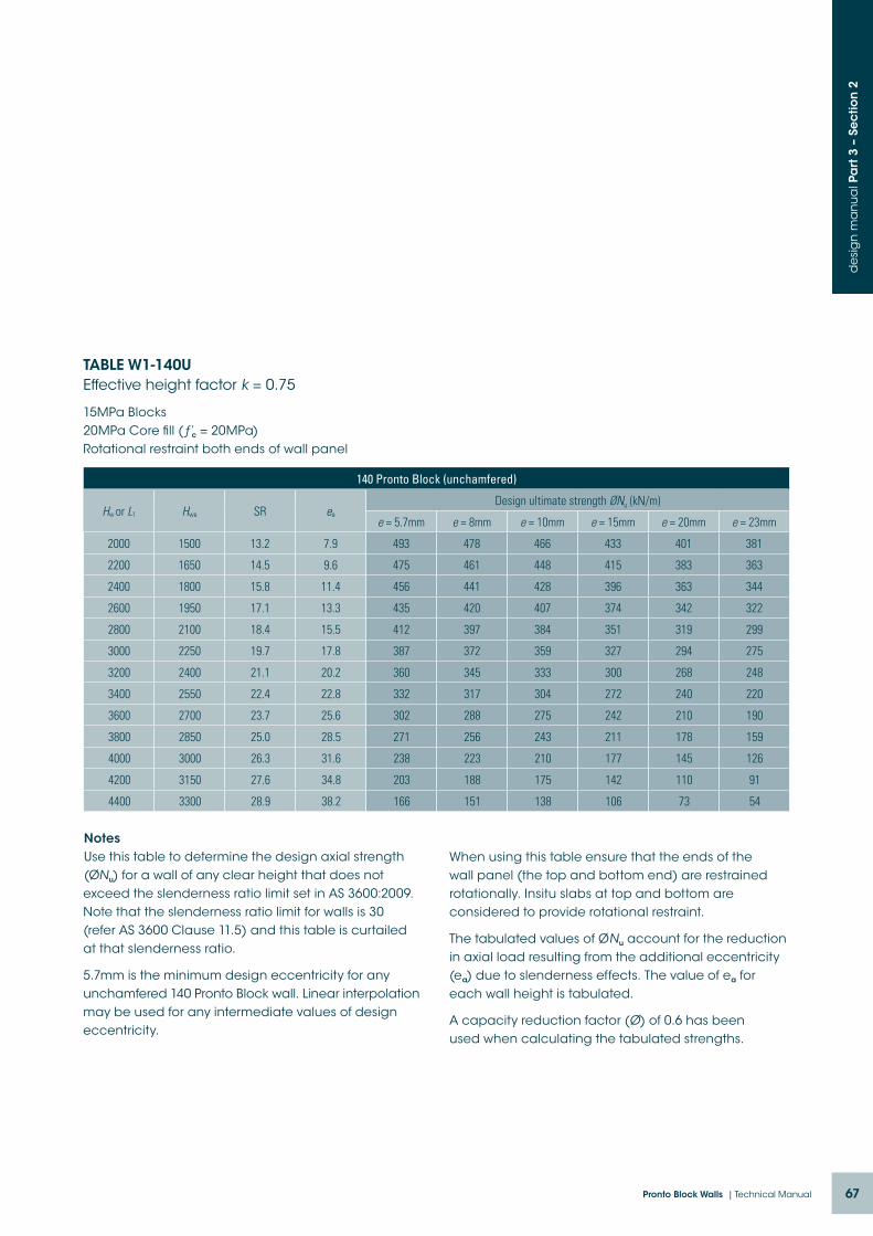
67Pronto Block Walls | Technical Manual
de
sig
n m
an
ua
l Pa
rt 3
– S
ec
tion
2
TABLE W1-140U Effective height factor k = 0.75
15MPa Blocks 20MPa Core fill (ƒ’c = 20MPa) Rotational restraint both ends of wall panel
140 Pronto Block (unchamfered)
Hw or L1 Hwe SR ea
Design ultimate strength ØNu (kN/m)
e = 5.7mm e = 8mm e = 10mm e = 15mm e = 20mm e = 23mm
2000 1500 13.2 7.9 493 478 466 433 401 381
2200 1650 14.5 9.6 475 461 448 415 383 363
2400 1800 15.8 11.4 456 441 428 396 363 344
2600 1950 17.1 13.3 435 420 407 374 342 322
2800 2100 18.4 15.5 412 397 384 351 319 299
3000 2250 19.7 17.8 387 372 359 327 294 275
3200 2400 21.1 20.2 360 345 333 300 268 248
3400 2550 22.4 22.8 332 317 304 272 240 220
3600 2700 23.7 25.6 302 288 275 242 210 190
3800 2850 25.0 28.5 271 256 243 211 178 159
4000 3000 26.3 31.6 238 223 210 177 145 126
4200 3150 27.6 34.8 203 188 175 142 110 91
4400 3300 28.9 38.2 166 151 138 106 73 54
NotesUse this table to determine the design axial strength (ØNu) for a wall of any clear height that does not exceed the slenderness ratio limit set in AS 3600:2009. Note that the slenderness ratio limit for walls is 30 (refer AS 3600 Clause 11.5) and this table is curtailed at that slenderness ratio.
5.7mm is the minimum design eccentricity for any unchamfered 140 Pronto Block wall. Linear interpolation may be used for any intermediate values of design eccentricity.
When using this table ensure that the ends of the wall panel (the top and bottom end) are restrained rotationally. Insitu slabs at top and bottom are considered to provide rotational restraint.
The tabulated values of ØNu account for the reduction in axial load resulting from the additional eccentricity (ea) due to slenderness effects. The value of ea for each wall height is tabulated.
A capacity reduction factor (Ø) of 0.6 has been used when calculating the tabulated strengths.

68 Austral Masonry
de
sig
n m
an
ua
l Pa
rt 3
– S
ec
tion
2
TABLE W2-140U Effective height factor k = 0.75
20MPa Blocks 20MPa Core fill (ƒ’c = 20MPa) Rotational restraint both ends of wall panel
140 Pronto Block (unchamfered)
Hw or L1 Hwe SR ea
Design ultimate strength ØNu (kN/m)
e = 5.7mm e = 8mm e = 10mm e = 15mm e = 20mm e = 23mm
2000 1500 13.2 7.9 658 638 621 578 534 508
2200 1650 14.5 9.6 634 614 597 554 510 485
2400 1800 15.8 11.4 608 588 571 527 484 458
2600 1950 17.1 13.3 579 560 542 499 456 430
2800 2100 18.4 15.5 549 529 512 468 425 399
3000 2250 19.7 17.8 516 496 479 435 392 366
3200 2400 21.1 20.2 481 461 443 400 357 331
3400 2550 22.4 22.8 443 423 406 363 319 294
3600 2700 23.7 25.6 403 383 366 323 280 254
3800 2850 25.0 28.5 361 341 324 281 238 212
4000 3000 26.3 31.6 317 297 280 236 193 167
4200 3150 27.6 34.8 270 250 233 190 147 121
4400 3300 28.9 38.2 221 201 184 141 98 72
NotesUse this table to determine the design axial strength (ØNu) for a wall of any clear height that does not exceed the slenderness ratio limit set in AS 3600:2009. Note that the slenderness ratio limit for walls is 30 (refer AS 3600 Clause 11.5) and this table is curtailed at that slenderness ratio.
5.7mm is the minimum design eccentricity for any unchamfered 140 Pronto Block wall. Linear interpolation may be used for any intermediate values of design eccentricity.
When using this table ensure that the ends of the wall panel (the top and bottom end) are restrained rotationally. Insitu slabs at top and bottom are considered to provide rotational restraint.
The tabulated values of ØNu account for the reduction in axial load resulting from the additional eccentricity (ea) due to slenderness effects. The value of ea for each wall height is tabulated.
A capacity reduction factor (Ø) of 0.6 has been used when calculating the tabulated strengths.
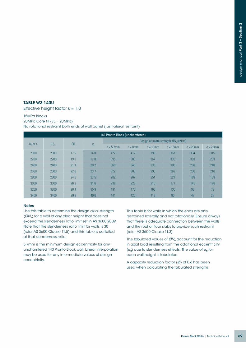
69Pronto Block Walls | Technical Manual
de
sig
n m
an
ua
l Pa
rt 3
– S
ec
tion
2
TABLE W3-140U Effective height factor k = 1.0
15MPa Blocks 20MPa Core fill (ƒ’c = 20MPa) No rotational restraint both ends of wall panel (just lateral restraint)
140 Pronto Block (unchamfered)
Hw or L1 Hwe SR ea
Design ultimate strength ØNu (kN/m)
e = 5.7mm e = 8mm e = 10mm e = 15mm e = 20mm e = 23mm
2000 2000 17.5 14.0 427 412 399 367 334 315
2200 2200 19.3 17.0 395 380 367 335 303 283
2400 2400 21.1 20.2 360 345 333 300 268 248
2600 2600 22.8 23.7 322 308 295 262 230 210
2800 2800 24.6 27.5 282 267 254 221 189 169
3000 3000 26.3 31.6 238 223 210 177 145 126
3200 3200 28.1 35.9 191 176 163 130 98 79
3400 3400 29.8 40.6 141 126 113 80 48 28
NotesUse this table to determine the design axial strength (ØNu) for a wall of any clear height that does not exceed the slenderness ratio limit set in AS 3600:2009. Note that the slenderness ratio limit for walls is 30 (refer AS 3600 Clause 11.5) and this table is curtailed at that slenderness ratio.
5.7mm is the minimum design eccentricity for any unchamfered 140 Pronto Block wall. Linear interpolation may be used for any intermediate values of design eccentricity.
This table is for walls in which the ends are only restrained laterally and not rotationally. Ensure always that there is adequate connection between the walls and the roof or floor slabs to provide such restraint (refer AS 3600 Clause 11.3)
The tabulated values of ØNu account for the reduction in axial load resulting from the additional eccentricity (ea) due to slenderness effects. The value of ea for each wall height is tabulated.
A capacity reduction factor (Ø) of 0.6 has been used when calculating the tabulated strengths.
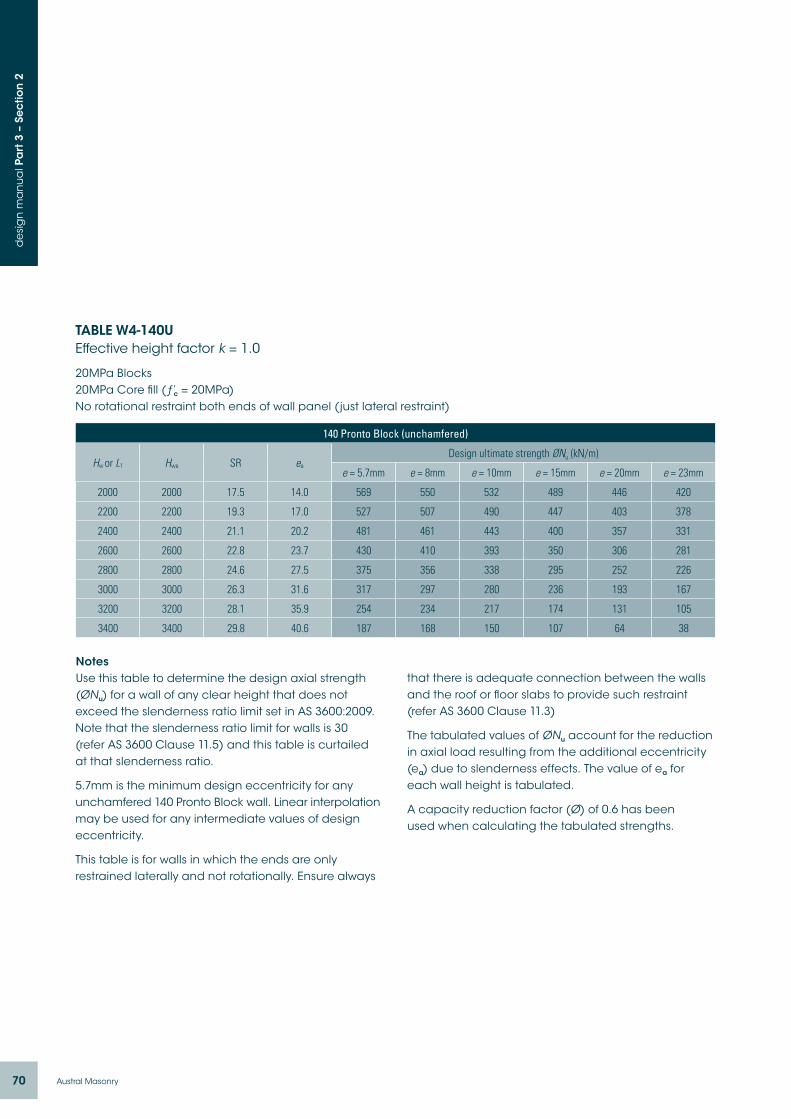
70 Austral Masonry
de
sig
n m
an
ua
l Pa
rt 3
– S
ec
tion
2
TABLE W4-140U Effective height factor k = 1.0
20MPa Blocks 20MPa Core fill (ƒ’c = 20MPa) No rotational restraint both ends of wall panel (just lateral restraint)
140 Pronto Block (unchamfered)
Hw or L1 Hwe SR ea
Design ultimate strength ØNu (kN/m)
e = 5.7mm e = 8mm e = 10mm e = 15mm e = 20mm e = 23mm
2000 2000 17.5 14.0 569 550 532 489 446 420
2200 2200 19.3 17.0 527 507 490 447 403 378
2400 2400 21.1 20.2 481 461 443 400 357 331
2600 2600 22.8 23.7 430 410 393 350 306 281
2800 2800 24.6 27.5 375 356 338 295 252 226
3000 3000 26.3 31.6 317 297 280 236 193 167
3200 3200 28.1 35.9 254 234 217 174 131 105
3400 3400 29.8 40.6 187 168 150 107 64 38
NotesUse this table to determine the design axial strength (ØNu) for a wall of any clear height that does not exceed the slenderness ratio limit set in AS 3600:2009. Note that the slenderness ratio limit for walls is 30 (refer AS 3600 Clause 11.5) and this table is curtailed at that slenderness ratio.
5.7mm is the minimum design eccentricity for any unchamfered 140 Pronto Block wall. Linear interpolation may be used for any intermediate values of design eccentricity.
This table is for walls in which the ends are only restrained laterally and not rotationally. Ensure always
that there is adequate connection between the walls and the roof or floor slabs to provide such restraint (refer AS 3600 Clause 11.3)
The tabulated values of ØNu account for the reduction in axial load resulting from the additional eccentricity (ea) due to slenderness effects. The value of ea for each wall height is tabulated.
A capacity reduction factor (Ø) of 0.6 has been used when calculating the tabulated strengths.

71Pronto Block Walls | Technical Manual
de
sig
n m
an
ua
l Pa
rt 3
– S
ec
tion
2
0
0.1
0.2
0.3
0.4
0.5
0.6
0.7
0.8
0.9
1
0 0.5 1 1.5 2.5 3 3.5 4 4.52
Restraint three sides only
Restraint four sides
k
DIAGRAM 2.1:
Refer AS 3600 Clauses 11.4b) and 11.4c)

72 Austral Masonry
de
sig
n m
an
ua
l Pa
rt 3
– S
ec
tion
2
TABLE W5-140U
15MPa Blocks 20MPa Core fill (ƒ’c = 20MPa)
140 Pronto Block (unchamfered)
SR ea
Design ultimate strength ØNu (kN/m)
e = 5.7mm e = 8mm e = 10mm e = 15mm e = 20mm e = 23mm
12 10.0 508 493 480 447 415 396
13 11.8 495 481 468 435 403 383
14 13.6 482 467 454 422 389 370
15 15.7 468 453 440 408 375 356
16 17.8 453 438 425 392 360 340
17 20.1 436 421 408 376 344 324
18 22.6 419 404 391 359 326 307
19 25.1 401 386 373 341 308 289
20 27.8 382 367 354 321 289 270
21 30.7 361 347 334 301 269 249
22 33.7 340 325 312 280 248 228
23 36.8 318 303 290 258 225 206
24 40.1 295 280 267 235 202 183
25 43.5 271 256 243 211 178 159
26 47.0 246 231 218 185 153 134
27 50.7 220 205 192 159 127 108
28 54.6 193 178 165 132 100 80
29 58.5 164 150 137 104 72 52
30 62.6 135 121 108 75 43 23
NotesUse this table to determine the design axial strength (ØNu) for a wall of any clear height that does not exceed the slenderness ratio limit set in AS 3600:2009. Note that the slenderness ratio limit for walls is 30 (refer AS 3600 Clause 11.5) and this table is curtailed at that slenderness ratio.
5.7mm is the minimum design eccentricity for any unchamfered 140 Pronto Block wall. Linear interpolation may be used for any intermediate values of design eccentricity.
This table is provided design engineers that are checking walls subjected to two-way buckling. It is valid also for walls subjected to one-way buckling but Tables W1 – W4 are more convenient for checking such walls.
The tabulated values of ØNu account for the reduction in axial load resulting from the additional eccentricity (ea) due to slenderness effects. The value of ea for each wall height is tabulated.

73Pronto Block Walls | Technical Manual
de
sig
n m
an
ua
l Pa
rt 3
– S
ec
tion
2
TABLE W6-140U
20MPa Blocks 20MPa Core fill (ƒ’c = 20MPa)
140 Pronto Block (unchamfered)
SR ea
Design ultimate strength ØNu (kN/m)
e = 5.7mm e = 8mm e = 10mm e = 15mm e = 20mm e = 23mm
12 6.6 677 657 640 597 553 528
13 7.7 661 641 623 580 537 511
14 8.9 643 623 606 562 519 493
15 10.3 624 604 587 543 500 474
16 11.7 603 584 566 523 480 454
17 13.2 582 562 545 501 458 432
18 14.8 559 539 522 478 435 409
19 16.5 535 515 497 454 411 385
20 18.2 509 489 472 429 385 359
21 20.1 482 462 445 402 358 333
22 22.1 454 434 417 373 330 304
23 24.1 424 404 387 344 301 275
24 26.3 393 373 356 313 270 244
25 28.5 361 341 324 281 238 212
26 30.8 328 308 291 247 204 178
27 33.2 293 273 256 213 169 143
28 35.8 257 237 220 176 133 107
29 38.3 219 199 182 139 96 70
30 41.0 181 161 143 100 57 31
NotesUse this table to determine the design axial strength (ØNu) for a wall of any clear height that does not exceed the slenderness ratio limit set in AS 3600:2009. Note that the slenderness ratio limit for walls is 30 (refer AS 3600 Clause 11.5) and this table is curtailed at that slenderness ratio.
5.7mm is the minimum design eccentricity for any unchamfered 140 Pronto Block wall. Linear interpolation may be used for any intermediate values of design eccentricity.
This table is provided design engineers that are checking walls subjected to two-way buckling. It is valid also for walls subjected to one-way buckling but Tables W1 – W4 are more convenient for checking such walls.
The tabulated values of ØNu account for the reduction in axial load resulting from the additional eccentricity (ea) due to slenderness effects. The value of ea for each wall height is tabulated.

74 Austral Masonry
de
sig
n m
an
ua
l Pa
rt 3
– S
ec
tion
3
section 3.Design of walls in bending
Bar position H2
Bar position H2 for load on side B
Bar position H2 for load on side A
A B
H2
V1 V1
AB
H2
This section is for the design of walls subjected to out-of-plane lateral loads only however it can also be used for the design of walls subjected to only small axial compression loads where the stress at mid-height due to bending and compression does not exceed the lesser of 0.03ƒ’c and 2MPa (Refer AS 3600 Clause 11.1b))
Reinforcing bar positionsThe location of all reinforcement in Pronto Block walls is controlled by the notches in the connectors that support the horizontal bars. The 140 mortarless connectors have three notches, and the bar positions are described as V1, V2, H1 and H2 as shown in the following skecthes. Positions V1 and H1 are located furthest from the neutral axis, while positions V2 and H2 are located closest to the neutral axis. These positions are referred to in the moment capacity tables below.

75Pronto Block Walls | Technical Manual
de
sig
n m
an
ua
l Pa
rt 3
– S
ec
tion
3
Bar position H1 for load on side B Bar position H1 for load on side A
A B
AB
H1
V2
H1
V2

76 Austral Masonry
de
sig
n m
an
ua
l Pa
rt 3
– S
ec
tion
3
Design Procedure: Bending
Out-of-plane bending (walls):
Step 1: Calculate ultimate limit state design bending moment.
Step 2: Select a Pronto Block size and strength (grade) based on local availability and any other requirements (fire rating, sound rating, thermal rating etc).
Step 3: Using Table 3.1 determine the reinforcement size, spacing and location that will give a bending moment capacity equal to or greater than the design bending moment.
Ensure the bar positions (vertical and/or horizontal) are specified on the drawings. Note that when the vertical bars are required to be in any of the four possible
locations it is necessary to specify the appropriate horizontal bar positions. The horizontal bars are used to guide the vertical bars into their correct location and to support them in that location throughout the height of the wall – refer to the sections on pages 74-75.
In-plane bending (beams):
Step 1: Calculate ultimate limit state design bending moment.
Step 2: Using Table 3.2 or 3.3 determine the reinforcement requirement noting that these tables can be used for checking both the positive and the negative bending moment reinforcement requirements.
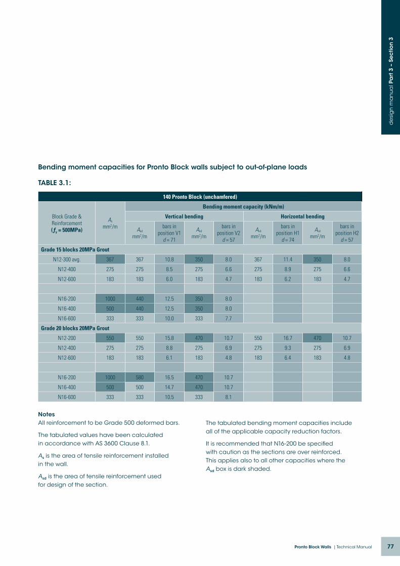
77Pronto Block Walls | Technical Manual
de
sig
n m
an
ua
l Pa
rt 3
– S
ec
tion
3
Bending moment capacities for Pronto Block walls subject to out-of-plane loads
TABLE 3.1:
140 Pronto Block (unchamfered)
Block Grade & Reinforcement (ƒy = 500MPa)
As mm2/m
Bending moment capacity (kNm/m)
Vertical bending Horizontal bending
Asd mm2/m
bars in position V1
d = 71
Asd mm2/m
bars in position V2
d = 57
Asd mm2/m
bars in position H1
d = 74
Asd mm2/m
bars in position H2
d = 57
Grade 15 blocks 20MPa Grout
N12-300 avg. 367 367 10.8 350 8.0 367 11.4 350 8.0
N12-400 275 275 8.5 275 6.6 275 8.9 275 6.6
N12-600 183 183 6.0 183 4.7 183 6.2 183 4.7
N16-200 1000 440 12.5 350 8.0
N16-400 500 440 12.5 350 8.0
N16-600 333 333 10.0 333 7.7
Grade 20 blocks 20MPa Grout
N12-200 550 550 15.8 470 10.7 550 16.7 470 10.7
N12-400 275 275 8.8 275 6.9 275 9.3 275 6.9
N12-600 183 183 6.1 183 4.8 183 6.4 183 4.8
N16-200 1000 580 16.5 470 10.7
N16-400 500 500 14.7 470 10.7
N16-600 333 333 10.5 333 8.1
NotesAll reinforcement to be Grade 500 deformed bars.
The tabulated values have been calculated in accordance with AS 3600 Clause 8.1.
As is the area of tensile reinforcement installed in the wall.
Asd is the area of tensile reinforcement used for design of the section.
The tabulated bending moment capacities include all of the applicable capacity reduction factors.
It is recommended that N16-200 be specified with caution as the sections are over reinforced. This applies also to all other capacities where the Asd box is dark shaded.
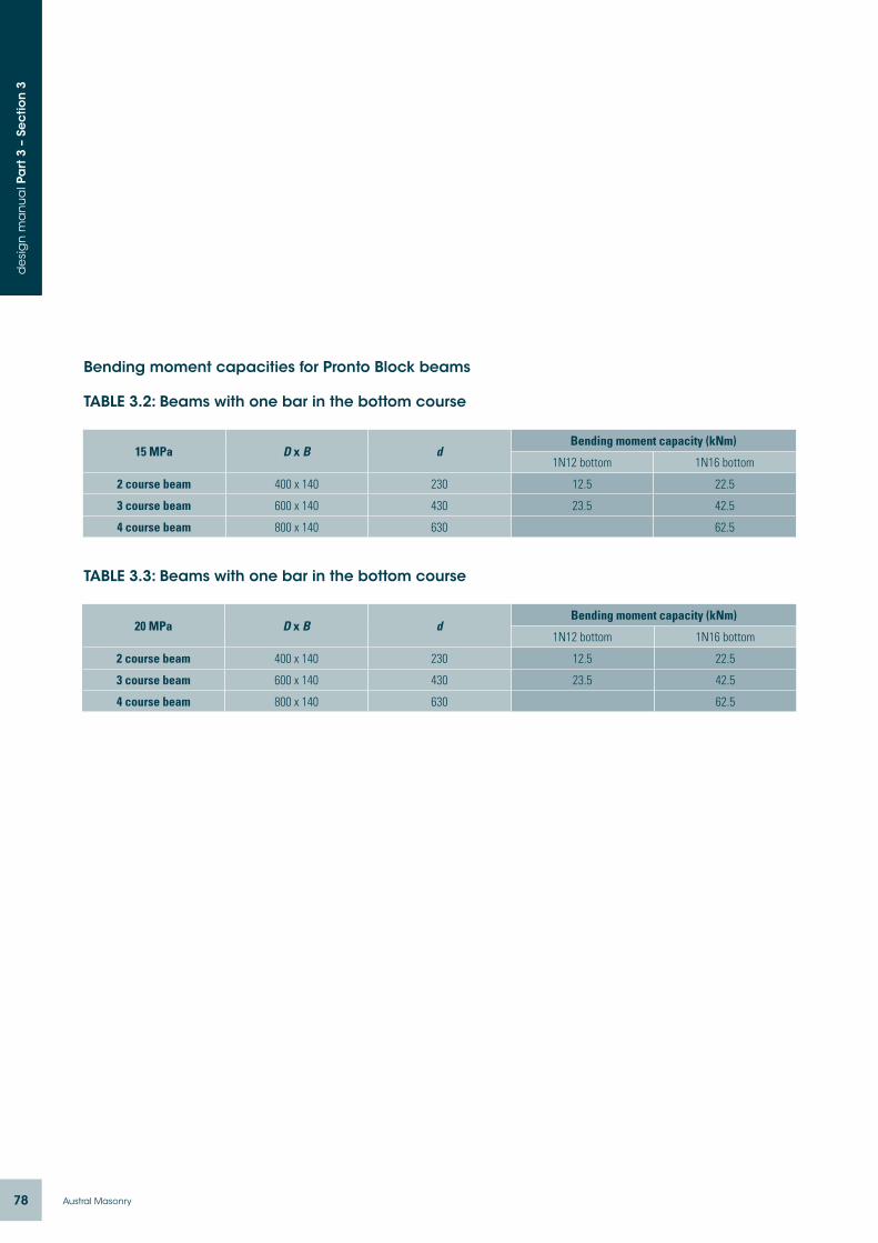
78 Austral Masonry
de
sig
n m
an
ua
l Pa
rt 3
– S
ec
tion
3
Bending moment capacities for Pronto Block beams
TABLE 3.2: Beams with one bar in the bottom course
15 MPa D x B dBending moment capacity (kNm)
1N12 bottom 1N16 bottom
2 course beam 400 x 140 230 12.5 22.5
3 course beam 600 x 140 430 23.5 42.5
4 course beam 800 x 140 630 62.5
TABLE 3.3: Beams with one bar in the bottom course
20 MPa D x B dBending moment capacity (kNm)
1N12 bottom 1N16 bottom
2 course beam 400 x 140 230 12.5 22.5
3 course beam 600 x 140 430 23.5 42.5
4 course beam 800 x 140 630 62.5
79Pronto Block Walls | Technical Manual
de
sig
n m
an
ua
l Pa
rt 3
– S
ec
tion
4
Section 2 of this manual deals with the design of walls for axial compression loads where the axial load capacity is determined in accordance with the simplified design method outlined in AS 3600 Clause 11.5. The tabulated values in Section 2 take into account both the design eccentricity of the axial load and the additional eccentricity resulting from slenderness.
Walls can also be subjected to out of plane lateral loads however that may increase the design bending moments. While axial compression loads can increase the moment capacity of a wall it is important to check that the increased design compressive stress in the extreme fibre of the concrete section does not exceed the permissible stress when the wall is subjected to the combined action.
In this Section of the design manual, interaction diagrams are provided for the purpose of checking combined bending and compression. These diagrams
section 4.design of pronto block walls for axial compression combined with out-of-plane bending
can be used to determine whether or not a critical section is over stressed due to the combined action.
There is no provision in AS 3600 for checking combined bending and compression using the simplified design method. The simplified design method takes into account the design bending moment due to eccentricity of the applied load at the top of the wall panel and it also takes into account the additional design bending moment due to slenderness effects but there is no provision for adding in any additional bending moment resulting from of out-of-plane lateral load.
When using the interaction diagrams it is very important to remember that the minimum design bending moment at any cross section is N* times 0.05td, i.e. the bending moment that corresponds to a minimum 5% design eccentricity.
The reinforcement requirements for the wall panel can be determined using the interaction diagrams.
Design Procedure: Combined axial compression and bending (one-way buckling)
This design procedure is for walls spanning vertically.
Step 1: Select a Pronto Block size and strength (grade) based on local availability and any other requirements (fire rating, sound rating, thermal rating etc).
Step 2: Carry out a structural analysis for all applicable load combinations to determine the ultimate limit state design compression load on the wall and the ultimate limit state design bending moments at the critical sections including the bending moments from slenderness effects and the bending moments from out-of-plane lateral loads.
Step 3: Use the interaction diagrams (Diagrams 4.1 and 4.2 on the following pages)
to check that the selected reinforcement
is adequate. Enter the interaction diagram
with the design axial load (N*) on the Y axis
and read off the maximum design bending
moment (M*) on the X axis. Check that the
actual design bending moment is less than
or equal to the maximum design bending
moment.
Step 4: If the wall is subject to in-plane lateral
load check the adequacy of the wall for
shear – refer to Section 5. It might also be
necessary to check the wall panel for
in-plane bending - Refer 9.1 in Part 1.
Step 5: If the wall is subjected to substantial
out-of-plane lateral load check the out-
of-plane shear stress – refer to Section 5
Fire, sound attenuation etc:
Step 6: Check that the wall satisfies all other
requirements in terms of durability,
slenderness, thickness etc.
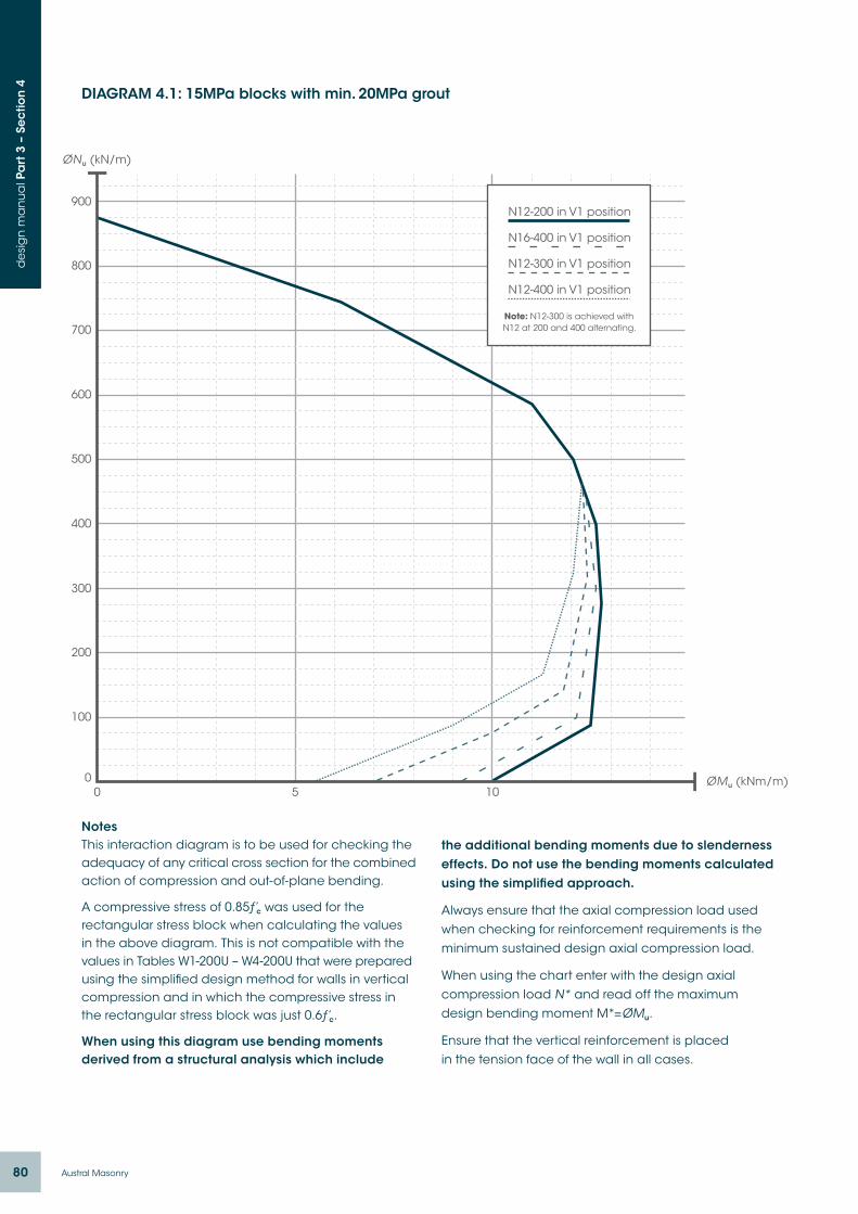
80 Austral Masonry
de
sig
n m
an
ua
l Pa
rt 3
– S
ec
tion
4 DIAGRAM 4.1: 15MPa blocks with min. 20MPa grout
NotesThis interaction diagram is to be used for checking the adequacy of any critical cross section for the combined action of compression and out-of-plane bending.
A compressive stress of 0.85ƒ’c was used for the rectangular stress block when calculating the values in the above diagram. This is not compatible with the values in Tables W1-200U – W4-200U that were prepared using the simplified design method for walls in vertical compression and in which the compressive stress in the rectangular stress block was just 0.6ƒ’c.
When using this diagram use bending moments derived from a structural analysis which include
the additional bending moments due to slenderness effects. Do not use the bending moments calculated using the simplified approach.
Always ensure that the axial compression load used when checking for reinforcement requirements is the minimum sustained design axial compression load.
When using the chart enter with the design axial compression load N* and read off the maximum design bending moment M*=ØMu.
Ensure that the vertical reinforcement is placed in the tension face of the wall in all cases.
0
100
200
300
400
500
600
700
800
900
0 5 10
N12-200 in V1 position
N16-400 in V1 position
N12-300 in V1 position
N12-400 in V1 position
Note: N12-300 is achieved withN12 at 200 and 400 alternating.

81Pronto Block Walls | Technical Manual
de
sig
n m
an
ua
l Pa
rt 3
– S
ec
tion
4DIAGRAM 4.2: 20MPa blocks with min. 20MPa grout
NotesThis interaction diagram is to be used for checking the adequacy of any critical cross section for the combined action of compression and out-of-plane bending.
A compressive stress of 0.85ƒ’c was used for the rectangular stress block when calculating the values in the above diagram. This is not compatible with the values in Tables W1-200U – W4-200U that were prepared using the simplified design method for walls in vertical compression and in which the compressive stress in the rectangular stress block was just 0.6ƒ’c.
When using this diagram use bending moments derived from a structural analysis which include
the additional bending moments due to slenderness effects. Do not use the bending moments calculated using the simplified approach.
Always ensure that the axial compression load used when checking for reinforcement requirements is the minimum sustained design axial compression load.
When using the chart enter with the design axial compression load N* and read off the maximum design bending moment M*=ØMu.
Ensure that the vertical reinforcement is placed in the tension face of the wall in all cases.
0
100
200
300
400
500
600
700
800
900
1000
1100
1200
0 5 10 15ØMu (kNm/m)
N12-200 in V1 position
N16-400 in V1 position
N12-300 in V1 position
N12-400 in V1 position
Note: N12-300 is achieved withN12 at 200 and 400 alternating.
82 Austral Masonry
de
sig
n m
an
ua
l Pa
rt 3
– S
ec
tion
5
Load-bearing walls are mostly designed to carry axial compression loads, however in many load bearing wall structures they are also designed to carry the lateral loads arising from wind, earthquake etc, i.e. they are designed as shear walls. Diagrams 5.1 and 5.2 in this Section provide a means of readily checking the capacity of a wall to take in-plane shear. The design strength of the wall is the sum of the values obtained from the two diagrams. It is necessary to use the correct reinforcement area when using Diagram 5.2 and this is explained in the notes below the diagram.
Load-bearing walls can also be subjected to out of plane lateral loads, a typical example being a
section 5.Design of Pronto Block Walls for shear
Design Procedure: Shear
In-Plane Shear (Shear Walls):Step 1: Calculate ultimate limit state design shear
force on the wall panel.
Step 2: Determine the shear strength of the wall panel (excluding the contribution from reinforcement) using Diagram 5.1. Note that the value obtained from Diagram 5.1 is the shear capacity per linear metre of the wall panel length, so simply multiply the value obtained from the Diagram by the length in metres to obtain the total shear capacity.
Step 3: Determine the contribution to shear strength of the wall reinforcement using Diagram 5.2. Again note that this gives the shear strength per linear metre and note that all reinforcement used when determining a value from this diagram must be anchored beyond the critical section.
In-Plane Shear (Beams):Step 1: Calculate ultimate limit state design shear
force on the beam at the critical section.
Step 2: Use Table 5.2 to determine whether the beam has adequate shear strength without the need for shear reinforcement. If not then proceed to Step 3.
Step 3: Use Table 5.2 to determine whether the beam has adequate shear strength with single leg R10 shear reinforcement. If not then select a deeper beam or use an alternative beam.
Out-Of-Plane Shear:Step 1: Calculate ultimate limit state design shear
force on the wall.
Step 2: Use Diagram 5.3 or 5.4 to determine the shear capacity of the wall and check that this is equal to or greater than the design shear force.
retaining wall designed to carry earth pressure loads. These walls may need to be checked for transverse shear loads at critical sections and Diagrams 5.3 and 5.4 in this Section are provided to make this task very easy. It can readily be seen in the diagram that the transverse shear capacity increases as the axial load N* increases.
Reinforced Pronto Block is also often used as lintel beams and the like to span across openings. These members need to be designed for shear the same as any reinforced concrete beam and Tables 5.1 and 5.2 in this Section make it very easy to check the shear capacity of Pronto Block beams.

83Pronto Block Walls | Technical Manual
de
sig
n m
an
ua
l Pa
rt 3
– S
ec
tion
4
DIAGRAM 5.1 – In-plane shear strength of Pronto Block shear walls excluding contribution of reinforcement
NotesThe shear strengths given in the above Diagram are kN per linear metre of wall length.
Critical section for shear is the lesser of 0.5Lw and 0.5Hw from the base of the wall (AS 3600 Clause 11.6.1).
This diagram takes no account of the contribution of the reinforcement to the shear strength.
For the contribution of reinforcement to shear strength refer Diagram 5.2.
A value of Ø=0.7 has been used in the calculations.
010
20
30
40
50
60
70
80
90
100
110
120
130
140
150
160
170
180
0 0.2 0.4 0.6 0.8 1 1.2 1.4 1.6 1.8 2 2.2 2.4 2.6 2.8
ƒ’c = 15MPa
ƒ’c = 20MPa
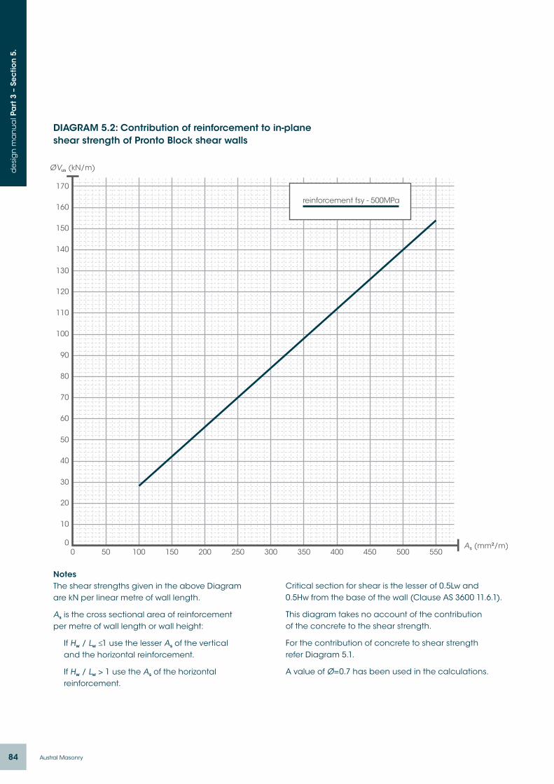
84 Austral Masonry
de
sig
n m
an
ua
l Pa
rt 3
– S
ec
tion
5.
0
10
20
30
40
50
60
70
80
90
100
110
120
130
140
150
160
170
0 50 100 150 200 250 300 350 400 450 500 550
reinforcement fsy - 500MPa
DIAGRAM 5.2: Contribution of reinforcement to in-plane shear strength of Pronto Block shear walls
NotesThe shear strengths given in the above Diagram are kN per linear metre of wall length.
As is the cross sectional area of reinforcement per metre of wall length or wall height:
If Hw / Lw ≤1 use the lesser As of the vertical and the horizontal reinforcement.
If Hw / Lw > 1 use the As of the horizontal reinforcement.
Critical section for shear is the lesser of 0.5Lw and 0.5Hw from the base of the wall (Clause AS 3600 11.6.1).
This diagram takes no account of the contribution of the concrete to the shear strength.
For the contribution of concrete to shear strength refer Diagram 5.1.
A value of Ø=0.7 has been used in the calculations.
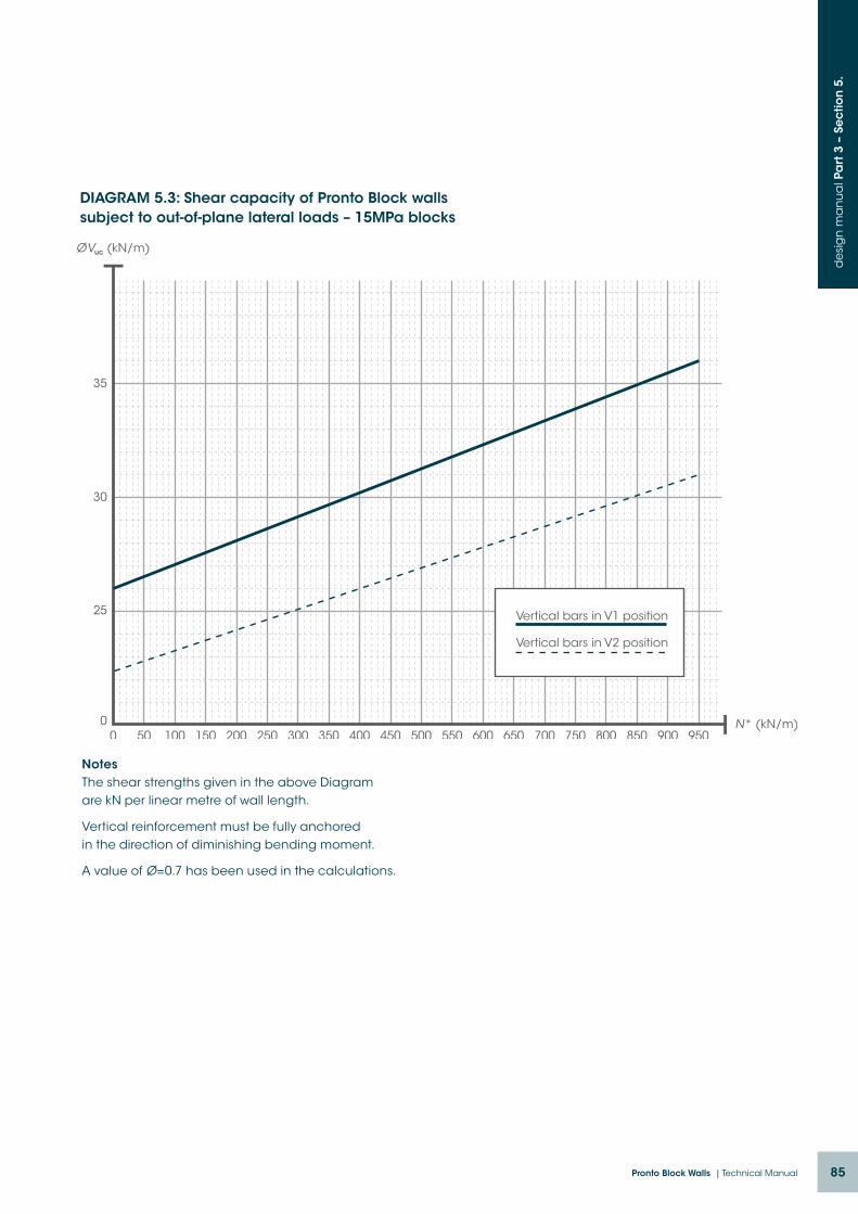
85Pronto Block Walls | Technical Manual
de
sig
n m
an
ua
l Pa
rt 3
– S
ec
tion
5.
0
25
30
35
0 50 100 150 200 250 300 350 400 450 500 550 600 650 700 750 800 850 900 950
Vertical bars in V1 position
Vertical bars in V2 position
DIAGRAM 5.3: Shear capacity of Pronto Block walls subject to out-of-plane lateral loads – 15MPa blocks
NotesThe shear strengths given in the above Diagram are kN per linear metre of wall length.
Vertical reinforcement must be fully anchored in the direction of diminishing bending moment.
A value of Ø=0.7 has been used in the calculations.
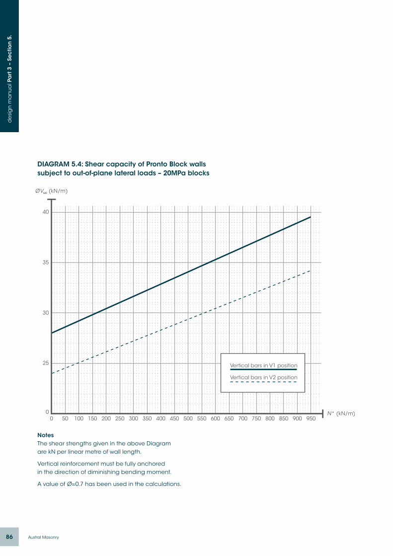
86 Austral Masonry
de
sig
n m
an
ua
l Pa
rt 3
– S
ec
tion
5.
0
25
30
35
40
0 50 100 150 200 250 300 350 400 450 500 550 600 650 700 750 800 850 900 950
Vertical bars in V1 position
Vertical bars in V2 position
DIAGRAM 5.4: Shear capacity of Pronto Block walls subject to out-of-plane lateral loads – 20MPa blocks
NotesThe shear strengths given in the above Diagram are kN per linear metre of wall length.
Vertical reinforcement must be fully anchored in the direction of diminishing bending moment.
A value of Ø=0.7 has been used in the calculations.
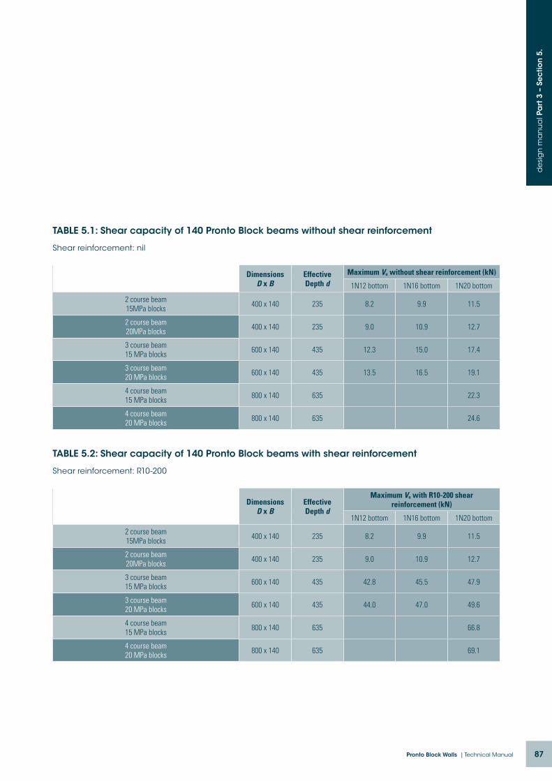
87Pronto Block Walls | Technical Manual
de
sig
n m
an
ua
l Pa
rt 3
– S
ec
tion
5.
TABLE 5.1: Shear capacity of 140 Pronto Block beams without shear reinforcement
Shear reinforcement: nil
Dimensions D x B
Effective Depth d
Maximum Vu without shear reinforcement (kN)
1N12 bottom 1N16 bottom 1N20 bottom
2 course beam 15MPa blocks
400 x 140 235 8.2 9.9 11.5
2 course beam 20MPa blocks
400 x 140 235 9.0 10.9 12.7
3 course beam 15 MPa blocks
600 x 140 435 12.3 15.0 17.4
3 course beam 20 MPa blocks
600 x 140 435 13.5 16.5 19.1
4 course beam 15 MPa blocks
800 x 140 635 22.3
4 course beam 20 MPa blocks
800 x 140 635 24.6
TABLE 5.2: Shear capacity of 140 Pronto Block beams with shear reinforcement
Shear reinforcement: R10-200
Dimensions D x B
Effective Depth d
Maximum Vu with R10-200 shear reinforcement (kN)
1N12 bottom 1N16 bottom 1N20 bottom
2 course beam 15MPa blocks
400 x 140 235 8.2 9.9 11.5
2 course beam 20MPa blocks
400 x 140 235 9.0 10.9 12.7
3 course beam 15 MPa blocks
600 x 140 435 42.8 45.5 47.9
3 course beam 20 MPa blocks
600 x 140 435 44.0 47.0 49.6
4 course beam 15 MPa blocks
800 x 140 635 66.8
4 course beam 20 MPa blocks
800 x 140 635 69.1

AM 7021 12/2014 BROWNINK
The range of building products from
A member of
Austral Masonry National OfficesNew South Wales 44 Clunies Ross Street Prospect NSW 2148
Tel +61 2 9840 2333 Fax +61 2 9840 2344
Queensland
184 Burnside Road Ormeau QLD 4208
PO Box 502 Beenleigh QLD 4207
Tel +61 7 3441 7500 Fax +61 7 3807 7033
Victoria 59 Elliott Road Dandenong VIC 3175
PO Box 4068 Dandenong South VIC 3164
Tel +61 3 9791 6988 Fax +61 3 9791 1644
1300 MASONRY (1300 627 667)www.australmasonry.com.au
Proud supporters