Embed Size (px)
Citation preview

Proof Testing to Achieve H-20 Load RatingOf Septic Tanks Reinforced With Macro Fibers
By: Ed Pennypacker JEPCOSALES, LLC
Wednesday May 29, 2013Guardian Concrete2140 Maxon RoadSchenectady, NY 12308

Abstract
Guardian Concrete paid an engineer to design septic tanks that will be H-20 rated. The engineer presented designs which include substantial steel reinforcing in the top slab, walls and floor of the tank. Using Macrofibers, it is known that concrete can be effectively reinforced, if used in sufficient dosage. By substituting fibers, $170.00 in steel costs and 4 man hours are saved.
In this case, a tank was made with six pounds of macrofibers per yard of concrete, and no steel whatsoever in the side walls. The floor and roof were steel reinforced exactly as shown by the engineer’s design. Another tank was made the same, with nine pounds of macrofibers per yard, and no steel in the side walls. A third tank was made according to the engineer’s design, with steel in side walls, floor and roof.
The engineer, using ASTM C-1227 as a guide, calculated that to achieve H-20 Load Rating the tanks had to endure without damage, a negative pressure of 12.5 inches of Hg as produced by vacuum testing. This includes, as prescribed in ASTM C-1227, a safety factor of 1.5.
12.5 inches Hg is roughly equivalent to a load of 900 pounds per square foot (PSF)
The tank made with steel reinforcing only, and the one with six pounds per yard, each developed a tiny crack at 10.0 inches of Hg. But it is suspected that a small imperfection in the top slab may have caused that small crack.
The one with nine pounds per yard held 12.5 inches Hg with no damage after removing the imperfection in the top slab.
The engineer drew a top slab with a vertical inter-locking lip that helped stabilize the side walls during the test process. Guardian chose to make the top slab with a 45 degree bevel which interacted with the sidewalls
Observations
Each tank was set on a bed of sand, which is thought to better equalize the load sustained by the floor of each tank. It was raining when the test started, so a portable tent was set-up to protect some of the equip-ment. Guardians boom truck handled the lids which were dry-fit before testing began.

The top slab is poured in a separate adjust-able mold. The top of the tank portion is hand finished by one of the workers. The dry fit was pretty good. There were some spots with irregu-larities, so additional thickness of ConSeal CS-102 butyl gasket was employed to seal the joint.
While the truck held the top slab, Bill brushes the concrete to insure a good seal.
Since the test procedure applies such a high physical load, most of which, impacts the side walls, it is important to have an interaction between the side walls and the top slab. While the engineer showed a rectangular portion on the top slab, Guardian chose to produce the bevel, which was easier to assemble. As the vacuum test proceeded, pressure forced downward on the top and inward on the walls. The two bev-elled edges help each other withstand the forces without damage.

The manhole opening at one end of the tank had to be torch dried. Then it was sprayed with adhesive, which held in place a special gasket from ConSeal, CS-367.
CS-367 seals well enough to prevent leaks, but after the test, it easily releases. Regular CS-102 would seal so tightly that it would cause damage to unseal the structure.
During the test, the manhole plug was sucked down into the opening. The gray CS-367 pre-vents leaks, while allowing easy disassembly.JEPCO SALES, LLC provided the test equip-ment. One end of the tank was sealed with CS-367 while the other end provided access to the tank for the equipment. Because the 24 inch openings are tapered, the 26 inch diameter test plate would not cover the opening. Plywood with CS-367 under it, and with an opening cut in it helped seal the opening

CS-102 is a black butyl gasket. The weight of the con-crete compresses it. Some excess butyl “squeezes out” indicating sufficient gasket material is in the joint to make a water tight seal. Neither water nor air ever passes through the gasket. In case of a leak, water sneaks past the gasket, where compression is insufficient. At least 50% compression is the goal.
Vacuum pressures exert a lot of force on a tank. When that happens, more of the butyl gasket squeezes out of the joint. As air is drawn from inside the tank, air pressure on the outside pushes inward on all six sides. The downward pressure is increased enough that we can simulate expected loads. A typical septic tank is buried less than three feet deep in a back yard. These tanks are made to sustain the weight of heavy trucks. They are suited to installations in parking lots and driveways.
At 12.5 inches of Hg on the gauges, the tanks passes the requirements for H-20 loading. Nine pounds of Macrofiber per yard of concrete was used as the primary reinforcement in the sidewalls of the tank. The floor and roof are reinforced as directed by engineer’s design. There is no steel in any of the sidewalls.
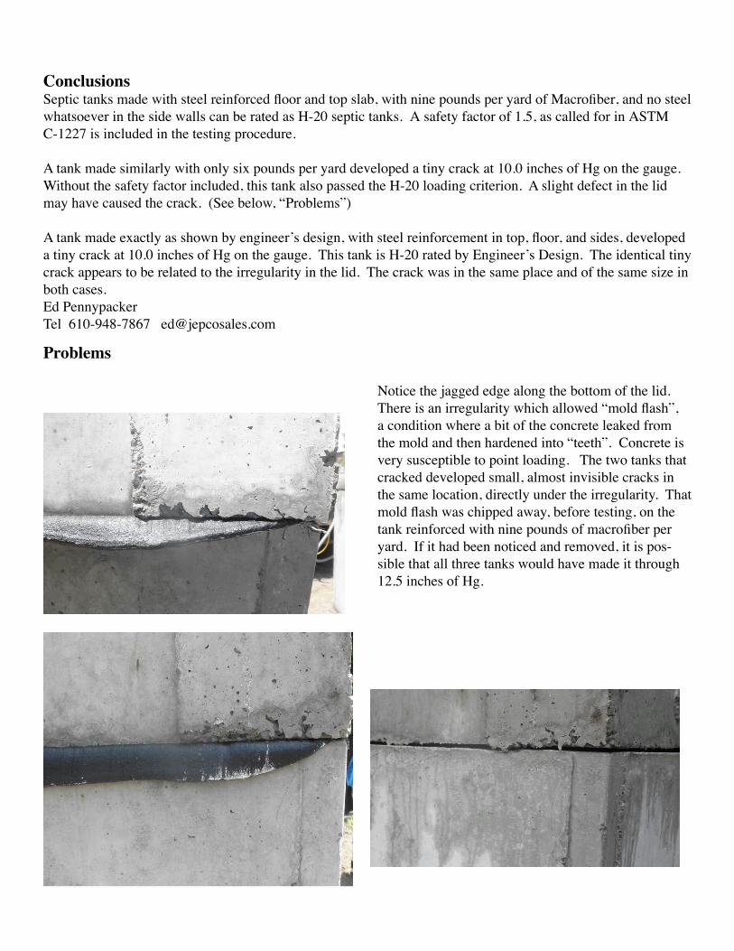
Conclusions Septic tanks made with steel reinforced floor and top slab, with nine pounds per yard of Macrofiber, and no steel whatsoever in the side walls can be rated as H-20 septic tanks. A safety factor of 1.5, as called for in ASTM C-1227 is included in the testing procedure.
A tank made similarly with only six pounds per yard developed a tiny crack at 10.0 inches of Hg on the gauge. Without the safety factor included, this tank also passed the H-20 loading criterion. A slight defect in the lid may have caused the crack. (See below, “Problems”)
A tank made exactly as shown by engineer’s design, with steel reinforcement in top, floor, and sides, developed a tiny crack at 10.0 inches of Hg on the gauge. This tank is H-20 rated by Engineer’s Design. The identical tiny crack appears to be related to the irregularity in the lid. The crack was in the same place and of the same size in both cases.Ed PennypackerTel 610-948-7867 [email protected]
Problems
Notice the jagged edge along the bottom of the lid. There is an irregularity which allowed “mold flash”, a condition where a bit of the concrete leaked from the mold and then hardened into “teeth”. Concrete is very susceptible to point loading. The two tanks that cracked developed small, almost invisible cracks in the same location, directly under the irregularity. That mold flash was chipped away, before testing, on the tank reinforced with nine pounds of macrofiber per yard. If it had been noticed and removed, it is pos-sible that all three tanks would have made it through 12.5 inches of Hg.