Embed Size (px)
Citation preview
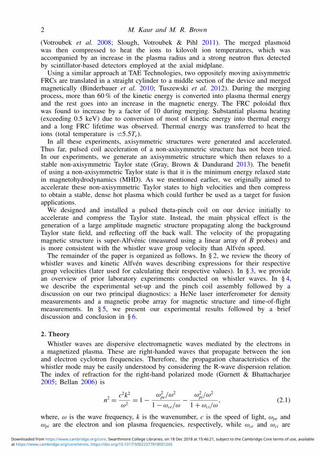
J. Plasma Phys. (2018), vol. 84, 905840614 c© Cambridge University Press 2018doi:10.1017/S0022377818001265
1
Propagation of a nonlinear wave packet driven ina relaxed magnetohydrodynamic plasma
M. Kaur1,† and M. R. Brown1
1Department of Physics and Astronomy, Swarthmore College, Swarthmore, Pennsylvania 19081, USA
(Received 25 May 2018; revised 21 November 2018; accepted 21 November 2018)
We report the observation of a nonlinear wave packet propagating through a relaxedTaylor state in the Swarthmore Spheromak eXperiment (SSX) device. The wave packetis launched by a fast, pulsed, high current (≈21 kA) single-turn theta-pinch coilmounted outside the plasma vessel. The theta-pinch coil is energized by discharginga 40 kV, 2 kJ capacitor circuit. The wave packet velocity is super-thermal andsuper-Alfvénic; its group velocity is more consistent with a whistler pulse than othercharacteristic velocities. We also observe a fast density pulse which indicates that itis not Alfvénic in nature.
Key words: astrophysical plasmas, plasma waves
1. IntroductionWe have been conducting compression experiments on the relaxed Taylor state in
the Swarthmore Spheromak eXperiment (SSX) device (Kaur et al. 2018a,b). In theseexperiments, the SSX plasma drifts away from the gun at 40 km s−1, stagnates ina closed conducting boundary and then gets compressed by 30 %. We measure theplasma parameters of the compressed plasma and identify events corresponding toadiabatic compression of the plasma. These events are used to identify the dominantequation of state. In these experiments, we found that the dynamics of weaklycollisional SSX plasmas is determined by the parallel Chew–Goldberger–Low (CGL)equations of state. This further suggests that the SSX plasma possesses an anisotropicvelocity distribution and has most of its proton energy in the parallel direction withrespect to the background magnetic field.
After achieving a compression of 30 % just due to the inertia of the plasma, weintended to accelerate our plasma to higher velocity such that it hits the end wallwith a greater momentum and hence achieves greater compression. We planned touse a series of staged theta-pinch coils. This technique has been used extensivelyto accelerate and compress axisymmetric plasma structures. In this technique, a setof electrically isolated and independently triggered pinch coils are used to translateand accelerate field reversed configurations (FRCs). In compression experimentson the Inductive Plasma Accelerator (IPA) device, two axisymmetric FRCs wereaccelerated to 300 km s−1 into a conical section using pinch coils and merged withcomplete magnetic FRC reconnection in the middle cylindrical section of the device
† Email address for correspondence: [email protected]
at https://www.cambridge.org/core/terms. https://doi.org/10.1017/S0022377818001265Downloaded from https://www.cambridge.org/core. Swarthmore College Libraries, on 18 Dec 2018 at 15:46:21, subject to the Cambridge Core terms of use, available
2 M. Kaur and M. R. Brown
(Votroubek et al. 2008; Slough, Votroubek & Pihl 2011). The merged plasmoidwas then compressed to heat the ions to kilovolt ion temperatures, which wasaccompanied by an increase in the plasma radius and a strong neutron flux detectedby scintillator-based detectors employed at the axial midplane.
Using a similar approach at TAE Technologies, two oppositely moving axisymmetricFRCs are translated in a straight cylinder to a middle section of the device and mergedmagnetically (Binderbauer et al. 2010; Tuszewski et al. 2012). During the mergingprocess, more than 60 % of the kinetic energy is converted into plasma thermal energyand the rest goes into an increase in the magnetic energy. The FRC poloidal fluxwas found to increase by a factor of 10 during merging. Substantial plasma heating(exceeding 0.5 keV) due to conversion of most of kinetic energy into thermal energyand a long FRC lifetime was observed. Thermal energy was transferred to heat theions (total temperature is w5.5Te).
In all these experiments, axisymmetric structures were generated and accelerated.Thus far, pulsed coil acceleration of a non-axisymmetric structure has not been tried.In our experiments, we generate an axisymmetric structure which then relaxes to astable non-axisymmetric Taylor state (Gray, Brown & Dandurand 2013). The benefitof using a non-axisymmetric Taylor state is that it is the minimum energy relaxed statein magnetohydrodynamics (MHD). As we mentioned earlier, we originally aimed toaccelerate these non-axisymmetric Taylor states to high velocities and then compressto obtain a stable, dense hot plasma which could further be used as a target for fusionapplications.
We designed and installed a pulsed theta-pinch coil on our device initially toaccelerate and compress the Taylor state. Instead, the main physical effect is thegeneration of a large amplitude magnetic structure propagating along the backgroundTaylor state field, and reflecting off the back wall. The velocity of the propagatingmagnetic structure is super-Alfvénic (measured using a linear array of B probes) andis more consistent with the whistler wave group velocity than Alfvén speed.
The remainder of the paper is organized as follows. In § 2, we review the theory ofwhistler waves and kinetic Alfvén waves describing expressions for their respectivegroup velocities (later used for calculating their respective values). In § 3, we providean overview of prior laboratory experiments conducted on whistler waves. In § 4,we describe the experimental set-up and the pinch coil assembly followed by adiscussion on our two principal diagnostics: a HeNe laser interferometer for densitymeasurements and a magnetic probe array for magnetic structure and time-of-flightmeasurements. In § 5, we present our experimental results followed by a briefdiscussion and conclusion in § 6.
2. TheoryWhistler waves are dispersive electromagnetic waves mediated by the electrons in
a magnetized plasma. These are right-handed waves that propagate between the ionand electron cyclotron frequencies. Therefore, the propagation characteristics of thewhistler mode may be easily understood by considering the R-wave dispersion relation.The index of refraction for the right-hand polarized mode (Gurnett & Bhattacharjee2005; Bellan 2006) is
n2=
c2k2
ω2= 1−
ω2pe/ω
2
1−ωce/ω−
ω2pi/ω
2
1+ωci/ω, (2.1)
where, ω is the wave frequency, k is the wavenumber, c is the speed of light, ωpe andωpi are the electron and ion plasma frequencies, respectively, while ωce and ωci are
at https://www.cambridge.org/core/terms. https://doi.org/10.1017/S0022377818001265Downloaded from https://www.cambridge.org/core. Swarthmore College Libraries, on 18 Dec 2018 at 15:46:21, subject to the Cambridge Core terms of use, available
Nonlinear wave prapagation through a relaxed plasma 3
the electron cyclotron and ion cyclotron frequencies, respectively. Since for whistlerwaves, the frequency of interest is well above the ion cyclotron frequency, the thirdterm on the right-hand side of (2.1) can be dropped and the dispersion relation forwhistler waves becomes,
c2k2
ω2=
ω2pe/ω
2
ωce/ω− 1. (2.2)
These waves propagate along the background magnetic field within a cone given bycosθ =ω/ωce, so for ω�ωce, they can propagate at almost any angle with respect toB0. In the limit of ω�ωce, the dispersion relation can be rewritten as follows:
ω=ωce
(ckωpe
)2
. (2.3)
From the above equation, it is clear that for whistlers, the frequency varies nonlinearlywith the wavenumber, so the group velocity ∂ω/∂k also has a dependence on k (andtherefore also on ω):
vg = 2c√ωωce
ωpe. (2.4)
As the group velocity is proportional to the square root of the frequency, the higherfrequencies propagate faster than the lower frequencies.
In addition to whistler waves, the plasma also supports other electromagnetic modesin magnetized plasma – the most ubiquitous mode being shear Alfvén waves. ShearAlfvén waves are low frequency electromagnetic waves that propagate below theion cyclotron frequency. The shear Alfvén waves exhibit two different propagatingcharacteristics depending on the dimensionless parameter β = v2
te/(ω/k‖)2, where
vte is the electron thermal velocity, ω is the frequency of the wave and k‖ is thewavenumber parallel to the ambient magnetic field. For β� 1, the shear Alfvén waveis called the kinetic Alfvén wave (Gekelman et al. 1997, 2011) while for β� 1, theshear Alfvén wave is referred to as the inertial Alfvén wave (Gekelman et al. 1997,2011). In our experiment β � 1 and the dispersion relation for the kinetic Alfvénwave is given by (Stasiewicz et al. 2000)
ω
k‖= vA
√1+ k2
⊥ρ2s
(1+
Ti
Te
)− ω2
(1+ k2
⊥ρ2s
Ti
Te
), (2.5)
where ω is the wave frequency normalized by the ion cyclotron frequency (ωci), k⊥ isperpendicular wavenumber, Ti and Te are the ion and electron temperature, respectively.ρs is the ion sound gyroradius (=
√Te/mi/ωci) and vA is the Alfvén speed, given by
vA =B
√4πnimi
, (2.6)
where mi, ni and B represent mass of ion, plasma density and magnetic field,respectively.
at https://www.cambridge.org/core/terms. https://doi.org/10.1017/S0022377818001265Downloaded from https://www.cambridge.org/core. Swarthmore College Libraries, on 18 Dec 2018 at 15:46:21, subject to the Cambridge Core terms of use, available

4 M. Kaur and M. R. Brown
The kinetic Alfvén wave usually propagates with a group velocity predominantlydirected along the ambient magnetic field lines. The parallel group velocity of kineticAlfvén wave is given by
vg‖KAW =∂ω
∂k‖=
vA
1+ k2⊥ρ
2s
(1+
Ti
Te
) {1+ k2⊥ρ2
s
(1+
Ti
Te
)− ω2
(1+ k2
⊥ρ2
sTi
Te
)}3/2
,
(2.7)where vg‖KAW
is the parallel group velocity.From equation (2.7), it is clear that vg‖KAW
of the kinetic Alfvén wave decreases asthe frequency approaches the ion cyclotron frequency. On the other hand, an increasein finite perpendicular wavenumber increases vg‖KAW
. However, when the perpendicularwavelength is much greater than the ion sound gyroradius (k2
⊥ρ2
s � 1) and the wavefrequency is much lower than the ion cyclotron frequency (ω2
� 1), the parallel groupvelocity becomes approximately equal to the Alfvén speed.
3. Overview of prior experiments of whistler waves in the laboratoryWhistler waves were originally observed in audio detection of radio waves a
century ago due to their characteristic falling whistle tone (Preece 1894; Storey1953; Barkhausen 1919). Laboratory studies of whistler waves were pioneered byR. L. Stenzel at UCLA. In over 50 papers, the Stenzel team carefully mapped outdispersion relations, phases and group velocities of whistler waves (Stenzel 1976,1999). The plasma device used a large BaO cathode (0.5 m) to produce a magnetized(0< B0 < 150 G), cold (Te 6 2 eV, Ti 6 0.2 eV), low density ne 6 1012 cm−3 plasma.Coherent whistler waves and bursts were excitated by either magnetic coils (Stenzel,Urrutia & Rousculp 1993; Rousculp, Stenzel & Urrutia 1995), or electrodes immersedin an afterglow plasma (Urrutia & Stenzel 1989; Urrutia, Stenzel & Rousculp 1994).
In the case of a magnetic coil antenna, when a short burst of current is applied,a detached structure is formed that propagates away from the antenna at the whistlergroup velocity (Stenzel & Urrutia 1990; Stenzel 1999). In some cases, the structure isa nearly spherical vortex. It can be demonstrated that the current density (J) in thesestructures is parallel to the wave magnetic field (Bwave) (i.e. J ∝ Bwave) so that thestructures can be thought of as force free in the context of electron MHD (EMHD). Asimple loop antenna launches whistler packets in both directions, with opposite EMHDhelicity.
In a sequence of over a dozen papers, the Stenzel group studied pulsed currentscarried by whistler structures (Urrutia & Stenzel 1989; Stenzel et al. 1993). In theseexperiments, the background magnetic field was very low (B0 6 20 G) so the ionswere unmagnetized. The experiments were performed in the afterglow discharge sothat the cathode currents were not present. The full three-dimensional magnetic fieldB(r, t) was mapped point-by-point from more than 105 highly repeatable shots, sothat the current density could be calculated directly by Ampere’s law, µ0J(r, t)=∇×
B(r, t). Measurements showed that indeed contours of components of B and J hadvery similar topologies.
When high currents are applied to the antenna, nonlinear effects are observed(Urrutia & Stenzel 1991, 1996). In some cases, wave fields can exceed the backgroundfield B0 (Stenzel, Urrutia & Strohmaier 2006), and the field energy density farexceeds the particle thermal energy (B
2/2µ0
∼= 104 nkT) (Urrutia & Stenzel 1991).In other words, the intense electromagnetic pulse from the antenna rapidly heats the
at https://www.cambridge.org/core/terms. https://doi.org/10.1017/S0022377818001265Downloaded from https://www.cambridge.org/core. Swarthmore College Libraries, on 18 Dec 2018 at 15:46:21, subject to the Cambridge Core terms of use, available
Nonlinear wave prapagation through a relaxed plasma 5
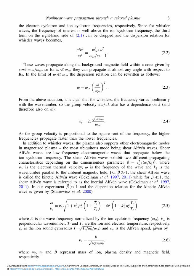
FIGURE 1. A schematic of the experimental set-up. A glass tube is added in betweenthe gun and the stagnation flux conserver (SFC) and is covered with a 53.3 cm longcopper flux conserving shell near the gun. A high permeability Permendur rod is installedat the centre of the inner electrode shell. Two principal plasma diagnostics are located inthe SFC. The plasma density, ne, is measured using HeNe laser interferometry along ahorizontal chord. The long B probe array is aligned along the axis of the SFC. The redlines on the magnetic probe array represent the locations of the B probes.
electrons. A high conductivity current channel produced by the hot electrons allowsthe nonlinear wave to penetrate anomalously into the collisional background plasma(Urrutia & Stenzel 1991). We believe that this mechanism could be at play duringour experiments with the theta-pinch coil.
4. Experimental set-upParcels of MHD plasma are produced using a magnetized coaxial plasma gun
located at one end of the linear device, as shown in figure 1. The diameter of theinner electrode of the gun is 6.2 cm and the outer electrode (i.e. flux conserver)diameter is 15 cm. More details about the plasma gun can be found in earlierpublications (Geddes, Kornack & Brown 1998; Brown & Schaffner 2014, 2015). Atthe other end of the linear chamber, a closed, tungsten-lined copper can, referredto here as a stagnation flux conserver (SFC), is installed. The SFC is 30 cm longand has the same inner diameter as the outer flux conserver of the gun. A 1 mlong quartz tube (diameter = 15 cm) is installed in between the gun and the SFC toaccommodate pinch coils in these experiments. One pinch coil has been installed onthe glass tube as shown in figure 1. The glass tube is partially covered with a copperflux conserving shell having a long magnetic soak time (>260 µs) to provide someflux conservation to the magnetized plasma in its relaxation phase. We maintain agood vacuum using a cryopump.
Tungsten-lined coaxial electrodes of the gun are cleaned by generating a He glowdischarge before experiments to obtain good wall conditions and to maintain a low-impurity plasma. A strong magnetic field (v1 T) is generated in the inner electrodeusing an external electromagnet and a strong ferromagnetic core. Hydrogen gas ispuffed into the annular region between the two electrodes using gas puff valves. Avoltage pulse (≈4 kV, 8 kJ) is applied between the two electrodes which ionizes thegas and causes a high current (v100 kA) to flow through the plasma. J × B forcesaccelerate the plasma out of the gun and a toroidal self-consistent magnetic object,called a spheromak (Geddes et al. 1998), is formed. The confining magnetic field is
at https://www.cambridge.org/core/terms. https://doi.org/10.1017/S0022377818001265Downloaded from https://www.cambridge.org/core. Swarthmore College Libraries, on 18 Dec 2018 at 15:46:21, subject to the Cambridge Core terms of use, available
6 M. Kaur and M. R. Brown
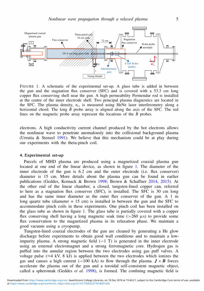
FIGURE 2. A schematic of the high voltage module showing the connections of theswitches and the capacitor to the theta-pinch coil. The line and arrows in the red colourshow the path of the current and its direction when the switch fires, whereas the same inthe blue colour corresponds to the crowbar firing.
convected along with the drifting spheromak and is sustained entirely by the currentsflowing in the plasma.
4.1. Description of the theta-pinch coil assembly
The theta-pinch coil assembly is made up of various high voltage components alongwith the theta-pinch coil itself. In this section, we will discuss about these componentsone by one.
4.1.1. Pinch coilIn order to accelerate the Taylor state moving at 40 km s−1 (i.e. 4 cm µs−1),
we aimed to keep the quarter-cycle rise time (t1/4 u (π/2)√
LC) near 1 µs. Ourcapacitance is 3 µF. Therefore, the design inductance of the single-turn coil mustbe u135 nH. We designed a 10.2 cm wide (i.e. axial length) single-turn coil withdiameter as 15.2 cm using a copper sheet of thickness 2.5 mm.
To reduce the inductance of the rest of the circuit, we made use of identical,multiple coaxial cable connections from the capacitor to the collector plates of thepinch coil. Each collector plate has nine 90 cm long coaxial cable connections. Theseplates are 15.2 cm wide to enable multiple coaxial cable connections and are taperedto 10.2 cm near the coil. The inductance due to the collector plates is below 15 nH.Total inductance of the nine RG213 coaxial cables is ≈27 nH. The quarter-cycle risetime for the entire circuit comes out to be u1 µs, which also determines the requireddelay between the switch and the crowbar.
at https://www.cambridge.org/core/terms. https://doi.org/10.1017/S0022377818001265Downloaded from https://www.cambridge.org/core. Swarthmore College Libraries, on 18 Dec 2018 at 15:46:21, subject to the Cambridge Core terms of use, available
Nonlinear wave prapagation through a relaxed plasma 7
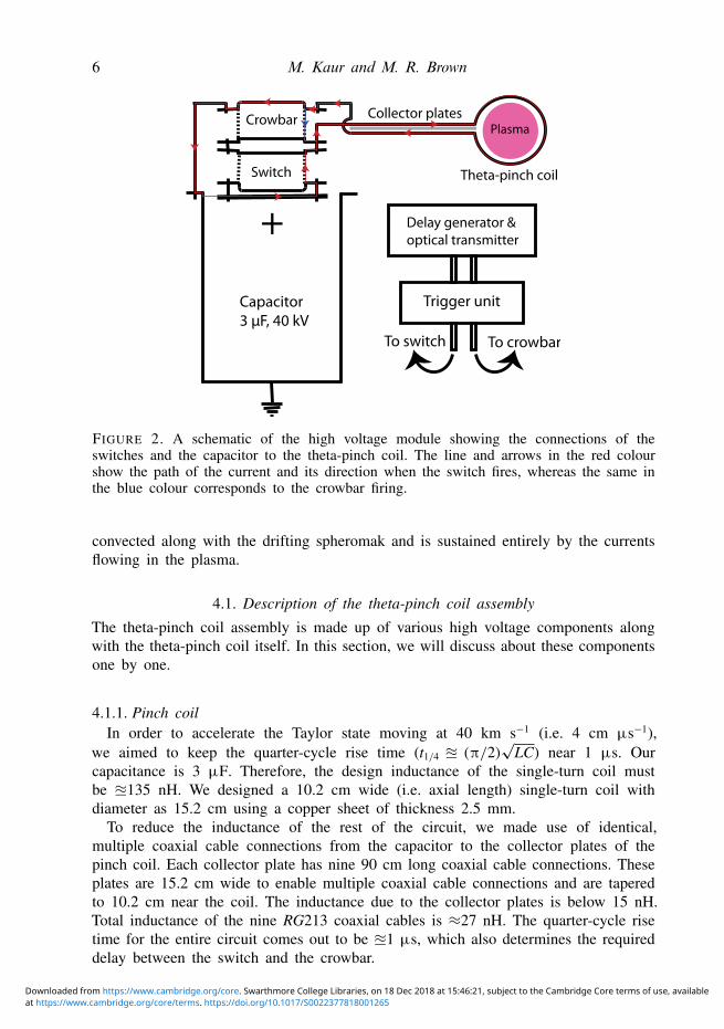
FIGURE 3. A schematic of the electronic circuit used for generating a pulsed magneticfield using the theta-pinch coil. Switch and crowbar are the Buchkov switches which arecapable of operating for more than 20 000 shots.
4.1.2. Electrical circuitA high voltage circuit has been developed for energizing the pinch coil and its
schematic is shown in figure 2. The capacitor is charged through a charging resistorusing a high-voltage (HV) power supply made by TDK Lambda, essentially a currentsource, which can charge the capacitor to 40 kV. To protect the power supply, weuse series and parallel combinations of high voltage diodes; each diode is rated upto 15 kV. The capacitor is connected to the coil through a HV pseudo-spark switch,often known as Buchkov switch (Buchkov et al. 2009; Slough et al. 2009) that candeliver current up to 200 kA at current rise rates up to 1012 A s−1. We use two ofthese switches in the circuit; one of these is used as a switch while the other is usedas a crowbar to prevent ringing (Slough et al. 2009). A schematic of the electroniccircuit is shown in figure 3. For safety purposes, there is a parallel circuit to dumpall the charge on the capacitor in a fraction of a second through a dump resistor. Thedump circuit makes use of a high voltage Ross relay rated to 40 kV.
Each switch has a dedicated heater voltage circuit and requires 5–15 min of heatingbefore the operation. The switches are triggered by using a high voltage pulse of1.6 kV. The high voltage pulses are applied using a pulsed circuit (provided byTri-Alpha Energy Technologies). The timing between the switch and the crowbar isadjusted using a Stanford Research Systems made delay generator (DG535) capableof operating at nanosecond precision. The output of the delay generator is convertedinto an optical pulse which triggers the Tri-Alpha Energy pulsed circuit for providingtrigger to the switch and the crowbar.
The gap between the two collector plates of the pinch coil is 3 mm. To preventarcing or breakdown in between the collector plates, we use a combination of highvoltage insulators. The insulation includes multiple alternate sheets of 5 mm thickKapton and polyethylene with paper sheets in between to prevent any space chargebuild-up. The entire combination is designed to work up to a dc voltage of 80 kV.
The switch and the crowbar along with their connections to the HV capacitor areimmersed in a high voltage insulation oil. The HV oil is STO-50 dielectric siliconefluid and has very low vapour pressure. It prevents high voltage discharge/arcing andis inert to virtually all metals, plastics and rubbers.
4.2. DiagnosticsFor these experiments, we rely on two principal diagnostics. We measure the lineaveraged electron density of the plasma along a horizontal chord with a 632.8nm HeNe laser Mach–Zehnder interferometer. Changes in plasma electron density
at https://www.cambridge.org/core/terms. https://doi.org/10.1017/S0022377818001265Downloaded from https://www.cambridge.org/core. Swarthmore College Libraries, on 18 Dec 2018 at 15:46:21, subject to the Cambridge Core terms of use, available
8 M. Kaur and M. R. Brown
introduce a change in the plasma frequency:
ωpe =
√4πe2ne
me. (4.1)
The refractive index of the plasma is related to the plasma frequency:
n2= 1−
ω2pe
ω2L, (4.2)
where ωL is the frequency of the incident laser beam. We can then use the lineintegrated phase difference introduced in the scene beam of the interferometer todetermine the line averaged plasma density over the path of the laser. This is doneby passing the reference beam through a quarter-wave plate to circularly polarize itand then recombining the scene beam and reference beam. The recombined beamis passed through a Wollaston prism to generate two outputs 90◦ out of phase witheach other, and the intensity of each of the two output beams is measured by usingtwo separate photodetectors.
Along with the laser interferometry, we use a long B probe array (encased in aquartz glass tube) along the axis of the SFC. The long probe is aligned almost alongthe axis of the SFC. The B probe has densely spaced (1.5 cm), single turn, twodirectional probes located inside the SFC, employed for determining the Taylor statestructure along the axis as well as its time of flight velocity. The array also has fewthree directional probes, which are co-located with the interferometry chord. Thesethree directional probes are used to measure the local vector magnetic field.
Apart from these two diagnostics, we use a 100-turn Rogowski coil to measure thecurrent flowing through the theta-pinch coil. It is mounted on the live end of the theta-pinch coil collector plate. The Rogowski coil is equipped with an RC integrator andshowed a linear frequency response from 200 kHz to 2 MHz.
5. Results and discussionPlasma parameters such as the electron density and magnetic field are measured in
the compression volume using HeNe laser interferometry and a linear B probe array,respectively. In these experiments, the theta-pinch coil is mounted 18 cm away fromthe front end of the SFC and it is 32 cm away from the interferometry port. Thisdistance was selected: (i) to avoid driving eddy currents in the vessel walls due tocoil firing, and (ii) to be able to easily detect the effect of the firing of the coil onthe Taylor states. We let the plasma reach the SFC and stagnate against the end wall.Then we carry out a delay scan by firing the coil at different times with respect to thetime it takes to reach the end wall. In this section, we will discuss about the resultsobtained using the density and the magnetic field data after firing the theta-pinch coil.
Magnetic field embedded in the structure in the compression volume is found to be≈300–400 G. Time-of-flight (ToF) velocity of the plasma from one probe location tothe next is determined by direct comparison of the magnetic field structures as wellas by carrying out a cross-correlation analysis. With the glass boundary, the typicalflow velocity of the plasma is found to be ≈40 km s−1, accompanied by a fast plasma(>60 km s−1) at the leading edge. The bulk of the plasma fills the SFC at ≈56 µs.
Immediately after the coil fires, we observe a magnetic wave packet/structurepropagating down the SFC with a mean velocity of 37 km s−1. A couple of
at https://www.cambridge.org/core/terms. https://doi.org/10.1017/S0022377818001265Downloaded from https://www.cambridge.org/core. Swarthmore College Libraries, on 18 Dec 2018 at 15:46:21, subject to the Cambridge Core terms of use, available
Nonlinear wave prapagation through a relaxed plasma 9
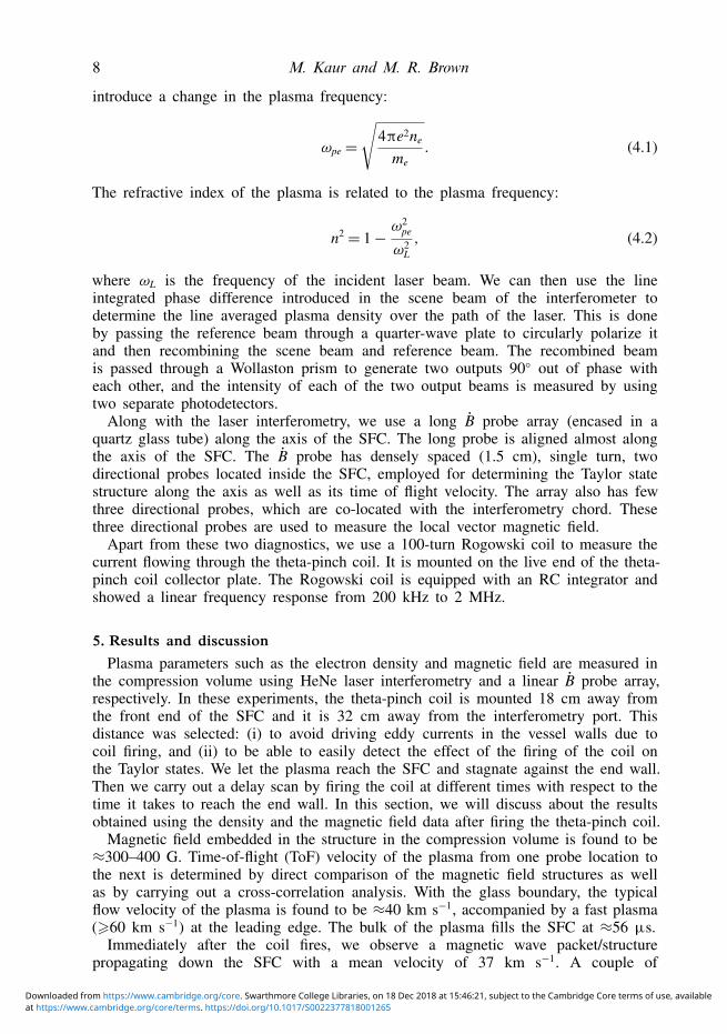
FIGURE 4. A typical x-component of the magnetic field obtained by using six B probesat different axial locations away from the SFC wall. Here, the probe located at 9 cm awayfrom the wall is the farthest probe with respect to the gun whereas the one at 16.5 cmfrom the wall is the closest to the gun and the interferometry chord. The black colour timetrace corresponds to the coil current flowing through the theta-pinch coil. High voltagecapacitor is charged to 33 kV and the coil current peaks at approximately 60 µs. Theuncertainty in the magnetic field measurements is <10 % and accounts for the errors dueto the numerical integration.
microseconds later, we see the same magnetic structure moving back towards thegun at 25 km s−1. After a careful analysis, we found that the magnetic structuregets reflected back from the end wall of the SFC. We do not observe this reflectionfor the shots in which we do not fire the theta-pinch coil. Velocity of the reflectedstructure is lower as compared to the forward traveling as the plasma is acceleratedonly in the beginning due to the J × B forces. After that, the structure keeps onmoving away from the gun due to its inertia and it’s velocity gradually decreases.
A typical magnetic field signal obtained using a set of six axial B probes (orientedin the same direction, i.e. Bx) after firing the pinch coil is shown in figure 4. In thisshot, the switch was fired at 58 µs and the crowbar was fired with a delay of 0.8 µs.Corresponding to these settings for the switches, the coil current peaks at '60 µs. Infigure 4, we can clearly see two counter-propagating signals. For the data presentedin this paper, we charged the capacitor to different voltages 25 kV, 30 kV and 33 kVand kept the gun parameters (such as direction and magnitude of stuffing flux, gasdelay and gun voltage) the same for each of the capacitor voltages.
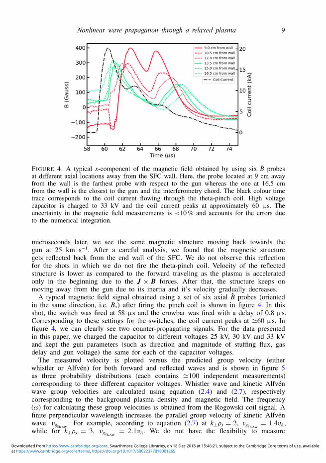
The measured velocity is plotted versus the predicted group velocity (eitherwhistler or Alfvén) for both forward and reflected waves and is shown in figure 5as three probability distributions (each contains '100 independent measurements)corresponding to three different capacitor voltages. Whistler wave and kinetic Alfvénwave group velocities are calculated using equation (2.4) and (2.7), respectivelycorresponding to the background plasma density and magnetic field. The frequency(ω) for calculating these group velocities is obtained from the Rogowski coil signal. Afinite perpendicular wavelength increases the parallel group velocity of kinetic Alfvénwave, vg‖KAW
. For example, according to equation (2.7) at k⊥ρs = 2, vg‖KAW= 1.4vA,
while for k⊥ρs = 3, vg‖KAW= 2.1vA. We do not have the flexibility to measure
at https://www.cambridge.org/core/terms. https://doi.org/10.1017/S0022377818001265Downloaded from https://www.cambridge.org/core. Swarthmore College Libraries, on 18 Dec 2018 at 15:46:21, subject to the Cambridge Core terms of use, available
10 M. Kaur and M. R. Brown
FIGURE 5. Contour plots for the velocity distribution of '300 measurementscorresponding to different capacitor voltages, showing the comparison of the measuredvelocity (along y-axis) with respect to the whistler wave group velocity (along the x-axis)for the forward and backward travelling magnetic structure in (a,b), and the same withrespect to the kinetic Alfvén waves (along the x-axis) in (c,d), respectively. In each panel,the dark blue colour corresponds to the most prominent measured and correspondingcalculated whistler (or Alfvén) velocity at 25 kV, the green colour at 30 kV and the redcolour at 33 kV (computed using background plasma density and magnetic field values).In each panel, the average velocities (measured and computed) have been marked andmentioned along with the error bars.
the perpendicular wavenumber. Therefore, in the absence of k⊥ measurements, wehave approximated the kinetic Alfvén wave group velocity to u2vA.
The vertical spread in the data corresponds to the spread in the ToF velocity(i.e. distance per time lag) measured using six magnetic probes located at differentaxial positions in the stagnation flux conserver (see figure 4). Each plasma shotprovides us with five values of velocity for the forward travelling magnetic structureand five for the reflected structure. If the measured velocity is equal to either the
at https://www.cambridge.org/core/terms. https://doi.org/10.1017/S0022377818001265Downloaded from https://www.cambridge.org/core. Swarthmore College Libraries, on 18 Dec 2018 at 15:46:21, subject to the Cambridge Core terms of use, available
Nonlinear wave prapagation through a relaxed plasma 11
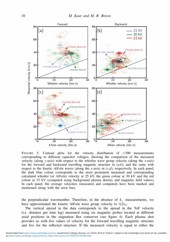
FIGURE 6. The average plasma density obtained from 8 shots for which the theta-pinchcoil was fired at 58 µs and the current flowing through the coil peaks at 60 µs. Thefiducial point A corresponds to the time when the Taylor state reaches the interferometrychord, B to the noise due to pinch coil firing, C to the fast density pulse and Dcorresponds to the second reflected density pulse. The fast density pulse (indicated bypoint C) is observed right after firing the coil in the interferometer cord which is located32 cm away from the pinch coil and is 19 cm away from the back end of the SFC. Theuncertainty in the density measurement is <10 %.
whistler velocity or Alfvén velocity, then the mean in the spread will be closer tothe diagonal line. The large vertical spread in the measured velocity could be dueto several possible reasons: (i) one of the reasons could be the different voltagesapplied to the pinch coil. For lower capacitor voltages (or lower currents flowingthrough the coil), the velocity distribution is near the bottom. Whereas for highercurrents, the overall velocity distribution seems to shift towards higher velocities.This is also reflected in figure 5. The gun generated plasma has a small shot-to-shotvariation, which could also contribute to this spread. In addition, the twisted Taylorstate has a small, but finite, azimuthal (rotational) velocity which can vary witheach shot. Since it is a non-axisymmetric structure so its coupling to the pinch coilmagnetic field (symmetric) could vary azimuthally. Our time of flight probes utilizejust one component of magnetic field so this azimuthal variation may introduce someuncertainty.
These data correspond to different plasma shots taken by keeping the gunparameters same but at three different values of magnetic field generated by thetheta-pinch coil, i.e. 1.3 kG, 1.5 kG and 1.7 kG corresponding to three differentcapacitor voltages, i.e. 25 kV, 30 kV and 33 kV. We observe that the mean velocityof the magnetic structure increases with an increase in the current flowing through thepinch coil. The theta-pinch coil magnetic field is, in all of the cases, more than fourtimes the magnetic field embedded in the plasma. We find that the observed forwardvelocity is closer to the whistler group velocity than the Alfvén group velocity.
In addition to the magnetic wave packet, we observe a fast density pulsepropagating through the SFC after we fire the pinch coil. The fast density pulseis detected using the HeNe laser interferometer. An average density trace from 8shots taken under the same conditions is shown in figure 6. Time of flight velocity
at https://www.cambridge.org/core/terms. https://doi.org/10.1017/S0022377818001265Downloaded from https://www.cambridge.org/core. Swarthmore College Libraries, on 18 Dec 2018 at 15:46:21, subject to the Cambridge Core terms of use, available
12 M. Kaur and M. R. Brown
of the fast density pulse is also measured. In this case, ToF velocity is measured (notshown in this paper) from the ratio of the axial distance of the coil from the locationof the density measurement chord to the delay in the observation of the fast densitypulse with respect to the time when the current flowing through the coil peaks.The coil is mounted 32 cm away from the density measurement chord. The timeof flight velocity measured using density pulses comes out to be close to the ionsound speed and is likely unrelated to the whistler pulse. We compared the velocitiesobtained using both time of fight methods; using density pulses and the magneticprobe signal. The time of flight velocity from the density pulse is different andfaster than that obtained from the magnetic probe analysis and could be addressedseparately in a future article.
There could be many possible explanations for the occurrence of these super-Alfvénic structures. We discuss about few of these here. Super-Alfvénic pulses havebeen measured in the solar wind and magnetosphere. In one set of the observations,the super-Alfvénic pulses, referred to as the magnetosonic shocklets (Stasiewiczet al. 2003), have been found to move at 250 km s−1, seven times faster than theAlfvén speed. In another observation of field-aligned ion beams near large amplitudemagnetic field fluctuations in the terrestrial foreshock, it is found that these structurespropagate (in the plasma frame) away from the bow shock toward the upstream(sunward) side of the short–large amplitude magnetic structures (Wilson et al. 2013).We do not claim that the magnetic structures observed in our experiments are sameas observed by the space plasma community; however, these space observations aresuggestive of possible mechanisms in our experiment.
In addition, there are a few more possible explanations for the observed discrepancyin the propagation speed of the magnetic structures. First, from figure 4 we see thatthe pinch coil pulse peaks to 20 kA, so the local magnetic field generated by the coilis '1.7 kG (B=µ0I/2R). This far exceeds the magnetic field embedded in the Taylorstate, which is '400 G. It is likely that the whistler pulse propagates in a large axialfield once formed.
Second, we only measure the line averaged density in the SFC and have notmeasured Te. It is possible that the large pinch coil pulse modifies the backgroundplasma, as was observed in the Stenzel experiments (Urrutia & Stenzel 1991), andprovides a nonlinear enhancement to the propagation speed.
Finally, the theta-pinch coil could launch several modes in the plasma as it is pulsedonly for a half-cycle, which means whistler wave and kinetic Alfvén wave calculationsshould take into account all the different frequencies excited. However to computethese group velocities, we approximate the pulse period to be four times the quarter-cycle rise time of the current flowing through the coil, observed in the Rogowski coil.In addition, we have approximated the kinetic Alfvén wave group velocity to u2vA byassuming k⊥ρs . 3 in the absence of k⊥ measurements. However, for higher values ofk⊥ρs, the group velocity of the kinetic Alfvén wave would be >2vA. A more detailedanalysis would involve both the nonlinear effects of the pinch coil current and thepropagation of multiple frequencies in the pulse. This analysis will be performed at alater time.
6. Summary
We measure the propagation of a nonlinear wave packet through a relaxed Taylorstate equilibrium. The wave packet is driven by passing a high current through a pinchcoil mounted outside the vacuum vessel, but coaxial with the glass tube. In these
at https://www.cambridge.org/core/terms. https://doi.org/10.1017/S0022377818001265Downloaded from https://www.cambridge.org/core. Swarthmore College Libraries, on 18 Dec 2018 at 15:46:21, subject to the Cambridge Core terms of use, available

Nonlinear wave prapagation through a relaxed plasma 13
experiments, we observe a wave packet propagating along the background magneticfield, into the SFC and then getting reflected back at the end wall. The forward andbackward time of flight velocity of the wave packet is measured using densely spacedB probes. The wave packet is found to move faster at higher currents flowing throughthe pinch coil. The measured velocity is compared with the characteristic velocitiesof the magnetized plasma such as the group velocity of the whistler waves and thekinetic Alfvén waves, and is found to be faster than both of the characteristic wavevelocities. However, the disagreement between the measured velocity of wave packetand the whistler velocity is less when compared with the group velocity of kineticAlfvén waves. In addition, the measured velocity is found to increase with an increasein the current flowing through the pinch coil.
AcknowledgementsThis work is supported by the Accelerating Low-Cost Plasma Heating and Assembly
(ALPHA) Program of the Advanced Research Projects Agency-Energy (ARPA-E). Wewish to acknowledge Tri-Alpha Energy Technologies Pvt. Ltd. for providing us highvoltage components, J. E. Shrock, I. Alfrey and T. Valentine for helping in theinstallation, D. A. Schaffner for various discussions, and S. Palmer and P. Jacobs fortheir technical support.
REFERENCES
BARKHAUSEN, H. 1919 Zwei mit Hilfe der neuen Verstärker entdeckte Erscheinungen. Phys. Z. 20,401–403.
BELLAN, P. M. 2006 Fundamentals of Plasma Physics. Cambridge University Press.BINDERBAUER, M. W., GUO, H. Y., TUSZEWSKI, M., PUTVINSKI, S., SEVIER, L., BARNES, D.,
ROSTOKER, N., ANDERSON, M. G., ANDOW, R., BONELLI, L. et al. 2010 Dynamic formationof a hot field reversed configuration with improved confinement by supersonic merging oftwo colliding high-β compact toroids. Phys. Rev. Lett. 105, 045003.
BROWN, M. R. & SCHAFFNER, D. A. 2014 Laboratory sources of turbulent plasma: a unique mhdplasma wind tunnel. Plasma Sources Sci. Technol. 23 (6), 063001.
BROWN, M. R. & SCHAFFNER, D. A. 2015 SSX MHD plasma wind tunnel. J. Plasma Phys. 81(3), 345810302.
BUCHKOV, V. D., BUCHKOV, D. V., DYAGILEV, V. M. & USHICH, V. G. 2009 Sn-series pseudosparkswitches operating completely without permanent heating: new prospects of application. ActaPhysica Polonica A 115 (6), 980–982.
GEDDES, C. G. R., KORNACK, T. W. & BROWN, M. R. 1998 Scaling studies of spheromakformation and equilibrium. Phys. Plasmas 5 (4), 1027–1034.
GEKELMAN, W., VINCENA, S., LENEMAN, D. & MAGGS, J. 1997 Laboratory experiments on shearalfvén waves and their relationship to space plasmas. J. Geophys. Res.: Space Physics 102(A4), 7225–7236.
GEKELMAN, W., VINCENA, S., VAN COMPERNOLLE, B., MORALES, G. J., MAGGS, J. E., PRIBYL,P. & CARTER, T. A. 2011 The many faces of shear Alfvén waves. Phys. Plasmas 18 (5),055501.
GRAY, T., BROWN, M. R. & DANDURAND, D. 2013 Observation of a relaxed plasma state in aquasi-infinite cylinder. Phys. Rev. Lett. 110 (8), 085002.
GURNETT, D. A. & BHATTACHARJEE, A. 2005 Introduction to Plasma Physics: With Space andLaboratory Applications. Cambridge University Press.
KAUR, M., BARBANO, L. J., SUEN-LEWIS, E. M., SHROCK, J. E., LIGHT, A. D., BROWN, M. R. &SCHAFFNER, D. A. 2018a Measuring the equations of state in a relaxed magnetohydrodynamicplasma. Phys. Rev. E 97, 011202.
at https://www.cambridge.org/core/terms. https://doi.org/10.1017/S0022377818001265Downloaded from https://www.cambridge.org/core. Swarthmore College Libraries, on 18 Dec 2018 at 15:46:21, subject to the Cambridge Core terms of use, available
14 M. Kaur and M. R. Brown
KAUR, M., BARBANO, L. J., SUEN-LEWIS, E. M., SHROCK, J. E., LIGHT, A. D., SCHAFFNER,D. A., BROWN, M. B., WOODRUFF, S. & MEYER, T. 2018b Magnetothermodynamics:measurements of the thermodynamic properties in a relaxed magnetohydrodynamic plasma.J. Plasma Phys. 84 (1), 905840114.
PREECE, W. H. 1894 Earth currents. Nature (London) 49, 554.ROUSCULP, C. L., STENZEL, R. L. & URRUTIA, J. M. 1995 Pulsed currents carried by whistlers.
V. Detailed new results of magnetic antenna excitation. Phys. Plasmas 2 (11), 4083–4093.SLOUGH, J., PIHL, C., BOCHKOV, V. D., BOCHKOV, D. V., PANOV, P. V. & GNEDIN, I. N. 2009
Prospective pulsed power applications of pseudospark switches. 17th IEEE International PulsedPower Conference, Washington, DC. pp. 255–259.
SLOUGH, J., VOTROUBEK, G. & PIHL, C. 2011 Creation of a high-temperature plasma throughmerging and compression of supersonic field reversed configuration plasmoids. Nucl. Fusion51 (5), 053008.
STASIEWICZ, K., BELLAN, P., CHASTON, C., KLETZING, C., LYSAK, R., MAGGS, J., POKHOTELOV,O., SEYLER, C., SHUKLA, P., STENFLO, L. et al. 2000 Small scale alfvénic structure in theaurora. Space Sci. Rev. 92 (3), 423–533.
STASIEWICZ, K., LONGMORE, M., BUCHERT, S., SHUKLA, P. K., LAVRAUD, B. & PICKETT, J.2003 Properties of fast magnetosonic shocklets at the bow shock. Geophys. Res. Lett. 30 (24),2241.
STENZEL, R. L. 1976 Whistler wave propagation in a large magnetoplasma. Phys. Fluids 19 (6),857–864.
STENZEL, R. L. 1999 Whistler waves in space and laboratory plasmas. J. Geophys. Res.: SpacePhys. 104 (A7), 14379–14395.
STENZEL, R. L. & URRUTIA, J. M. 1990 Force-free electromagnetic pulses in a laboratory plasma.Phys. Rev. Lett. 65, 2011–2014.
STENZEL, R. L., URRUTIA, J. M. & ROUSCULP, C. L. 1993 Pulsed currents carried by whistlers.Part I. Excitation by magnetic antennas. Phys. Fluids B 5 (2), 325–338.
STENZEL, R. L., URRUTIA, J. M. & STROHMAIER, K. D. 2006 Whistler modes with wave magneticfields exceeding the ambient field. Phys. Rev. Lett. 96, 095004.
STOREY, L. R. O. 1953 An investigation of whistling atmospherics. Phil. Trans. R. Soc. Lond. 246(908), 113–141.
TUSZEWSKI, M., SMIRNOV, A., THOMPSON, M. C., KOREPANOV, S., AKHMETOV, T., IVANOV,A., VOSKOBOYNIKOV, R., SCHMITZ, L., BARNES, D., BINDERBAUER, M. W. et al. 2012Field reversed configuration confinement enhancement through edge biasing and neutral beaminjection. Phys. Rev. Lett. 108, 255008.
URRUTIA, J. M. & STENZEL, R. L. 1989 Transport of current by whistler waves. Phys. Rev. Lett.62, 272–275.
URRUTIA, J. M. & STENZEL, R. L. 1991 Nonlinear penetration of whistler pulses into collisionalplasmas via conductivity modifications. Phys. Rev. Lett. 67, 1867–1870.
URRUTIA, J. M. & STENZEL, R. L. 1996 Pulsed currents carried by whistlers. VI. Nonlinear effects.Phys. Plasmas 3 (7), 2589–2598.
URRUTIA, J. M., STENZEL, R. L. & ROUSCULP, C. L. 1994 Pulsed currents carried by whistlers.II. Excitation by biased electrodes. Phys. Plasmas 1 (5), 1432–1438.
VOTROUBEK, G., SLOUGH, J., ANDREASON, S. & PIHL, C. 2008 Formation of a stable field reversedconfiguration through merging. J. Fusion Energy 27 (1), 123–127.
WILSON, L. B., KOVAL, A., SIBECK, D. G., SZABO, A., CATTELL, C. A., KASPER, J. C., MARUCA,B. A., PULUPA, M., SALEM, C. S. & WILBER, M. 2013 Shocklets, slams, and field alignedion beams in the terrestrial foreshock. J. Geophys. Res.: Space Phys. 118 (3), 957–966.
at https://www.cambridge.org/core/terms. https://doi.org/10.1017/S0022377818001265Downloaded from https://www.cambridge.org/core. Swarthmore College Libraries, on 18 Dec 2018 at 15:46:21, subject to the Cambridge Core terms of use, available