Embed Size (px)
Citation preview

1Pro-Panel™ LED User Guide
1X2 Panel
2X2 Panel
v2.0with On-Board Controls
V2 LED SOFTLIGHT USER GUIDE

2 Pro-Panel™ LED User Guide
What’s in the Box ................................................................................................................. 2
Features ............................................................................................................................... 3
Cautions & Warnings ........................................................................................................... 3
Operations, Storage & Handling ........................................................................................... 3
Technical Specifications ...................................................................................................... 4
Product Diagram .................................................................................................................. 5
Adjusting Yoke Handle ......................................................................................................... 6
AC & DC Power Connection ................................................................................................ 7
Operations & Programming ................................................................................................. 8
Protection Circuit ................................................................................................................. 8
Linking DMX Cable Connections .......................................................................................... 9
Setting Up Master or Slave ................................................................................................ 10
Connecting to the DMX512 Network .................................................................................. 10
DMX vs Dimming & Kevin Tables....................................................................................... 11
Remote DMX Dimming & Color Temperature Controller .................................................... 12
Remote Controller .............................................................................................................. 13
DMX Termination Resistor Switch & USB Input ................................................................. 14
Installing Hardware Accessories ....................................................................................... 15
WHAT’S IN THE BOX:
Light Panel and Yoke Assembled
4-Pin DMX Cable (for Controller Extension)
5-Pin DMX Cable (for Connecting Multiple Fixtures)
3m 120V Power Cord
90º Honey Comb Louver
1
2
3
4
5
2 5
1
3 4
TABLE OF CONTENTS

3Pro-Panel™ LED User Guide
• WARNING RISK OF ELECTRIC SHOCK! Turn off all power switches on the Pro-Panel fixture before connecting ordisconnecting any AC power or control cables (main or jumpers).
• WARNING RISK OF ELECTRIC SHOCK! - Do not use in wet or damp operating locations (condensing humidity hazard).
• WARNING RISK OF ELECTRIC SHOCK! - Do not insert any tools or metallic objects into any gap in the fixture.
• WARNING RISK OF ELECTRIC SHOCK! Do not open the case, modify, or change any component of the product.
• Over Heating! - Do not cover or wrap the fixture with any cloth, textile, tape, or plastic during operation.
• Failure to abide by any of the above warnings will void the product warranty.
• WARNING! Securely tighten the yoke and any light stand connections before operation. Only use mounting hardware rated for the weightof the fixture.
• WARNING! When hanging the fixture from a truss the use of a safety cable is mandatory. Only hang in accordance to local safety lawsand regulations.
• Use and install this product only according to this operation manual and or local safety laws and regulations.
• CAUTION! Do not connect a DMX Control Console and the Pro-Panel Remote Controller at the same time. This will causethe interruption and improper operation of the light.
• CAUTION! Keep the panel upright during storage and transportation to prevent pressure and damage to the diffuser andLED board inside.
• CAUTION! Do not apply any pressure to the diffuser panel. This may crack the diffuser and or damage the LED board.
• Turn off all power and disconnect power cables prior to cleaning.
• Use only a clean dry cloth to clean the fixture. Do not spray any liquids onto or into the fixture.
• 2700K Tungsten - 6500K Daylight Controllable Range
• Continuous DMX 512 Dimming Control: 100%-0%
• Connect Multiple Fixtures for Uniform Dimming and Color Temperature Control
• Flicker Free DC Driving System
• CRI up to 95
• Heavy Duty Adjustable Yoke: Capable of Hanging in Studio or PortableStand Mounting
• 1-Year Warranty
• Certifications: UL, FCC, and CE
• Max. Power Consumption: 100W < 1A
• 90-240V AC Input Range
APPLICATIONS:• Cinematography
• Video Broadcasting
• Professional Photography
CAUTIONS & WARNINGS!
OPERATION, STORAGE & HANDLING
FEATURES
4 Pro-Panel™ LED User Guide
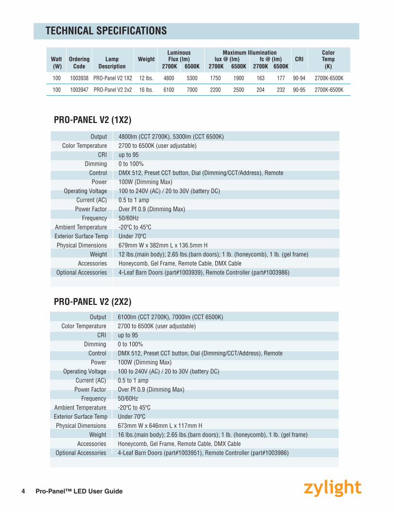
Luminous Maximum Illumination Color Watt Ordering Lamp Weight Flux (lm) lux @ (lm) fc @ (lm) CRI Temp (W) Code Description 2700K 6500K 2700K 6500K 2700K 6500K (K)
100 1003938 PRO-Panel V2 1X2 12 lbs. 4800 5300 1750 1900 163 177 90-94 2700K-6500K
100 1003947 PRO-Panel V2 2x2 16 lbs. 6100 7000 2200 2500 204 232 90-95 2700K-6500K
TECHNICAL SPECIFICATIONS
Output 4800lm (CCT 2700K), 5300lm (CCT 6500K) Color Temperature 2700 to 6500K (user adjustable) CRI up to 95 Dimming 0 to 100% Control DMX 512, Preset CCT button, Dial (Dimming/CCT/Address), Remote Power 100W (Dimming Max) Operating Voltage 100 to 240V (AC) / 20 to 30V (battery DC) Current (AC) 0.5 to 1 amp Power Factor Over Pf 0.9 (Dimming Max) Frequency 50/60Hz Ambient Temperature -20ºC to 45ºC Exterior Surface Temp Under 70ºC Physical Dimensions 679mm W x 382mm L x 136.5mm H Weight 12 lbs.(main body); 2.65 lbs.(barn doors); 1 lb. (honeycomb), 1 lb. (gel frame) Accessories Honeycomb, Gel Frame, Remote Cable, DMX Cable Optional Accessories 4-Leaf Barn Doors (part#1003939), Remote Controller (part#1003986)
Output 6100lm (CCT 2700K), 7000lm (CCT 6500K) Color Temperature 2700 to 6500K (user adjustable) CRI up to 95 Dimming 0 to 100% Control DMX 512, Preset CCT button, Dial (Dimming/CCT/Address), Remote Power 100W (Dimming Max) Operating Voltage 100 to 240V (AC) / 20 to 30V (battery DC) Current (AC) 0.5 to 1 amp Power Factor Over Pf 0.9 (Dimming Max) Frequency 50/60Hz Ambient Temperature -20ºC to 45ºC Exterior Surface Temp Under 70ºC Physical Dimensions 673mm W x 646mm L x 117mm H Weight 16 lbs.(main body); 2.65 lbs.(barn doors); 1 lb. (honeycomb), 1 lb. (gel frame) Accessories Honeycomb, Gel Frame, Remote Cable, DMX Cable Optional Accessories 4-Leaf Barn Doors (part#1003951), Remote Controller (part#1003986)
PRO-PANEL V2 (1X2)
PRO-PANEL V2 (2X2)
5Pro-Panel™ LED User Guide
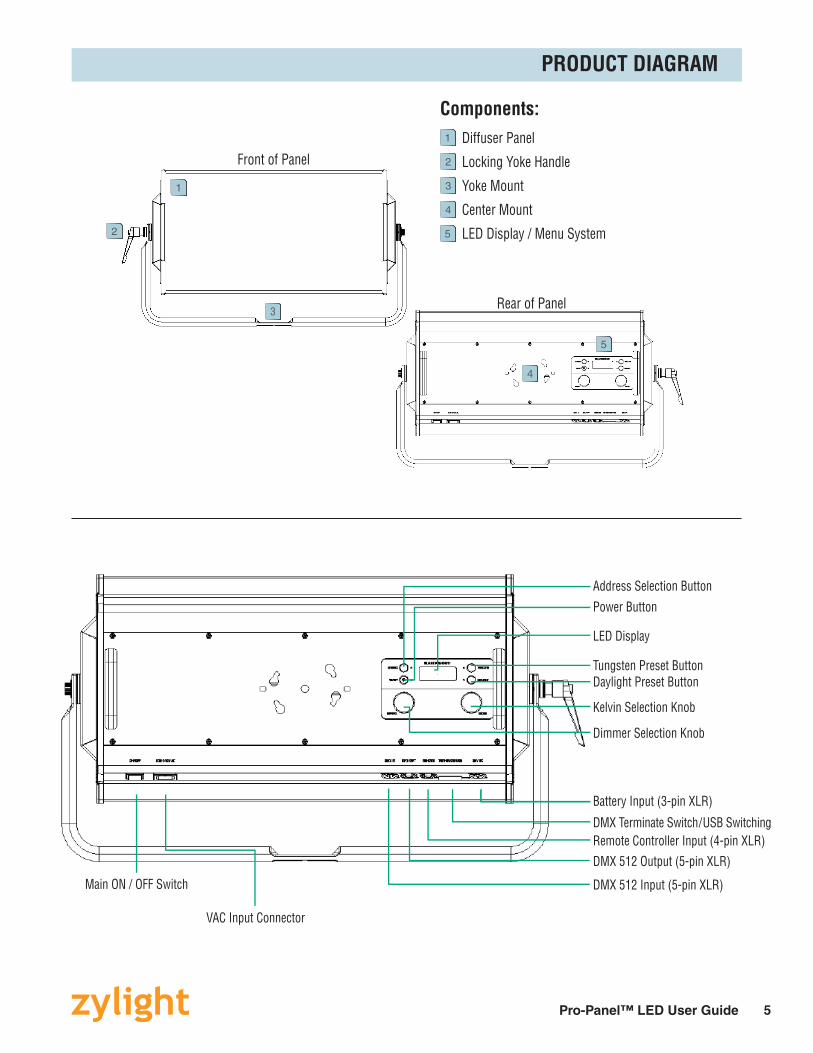
Components: Diffuser Panel
Locking Yoke Handle
Yoke Mount
Center Mount
LED Display / Menu System
1
2
3
4
5
PRODUCT DIAGRAM
Rear of Panel
4
5
1
2
3
Front of Panel
Main ON / OFF Switch
VAC Input Connector
DMX 512 Input (5-pin XLR)
DMX 512 Output (5-pin XLR)Remote Controller Input (4-pin XLR)DMX Terminate Switch / USB Switching
Dimmer Selection Knob
Kelvin Selection Knob
Daylight Preset ButtonTungsten Preset Button
Address Selection Button
Power Button
LED Display
Battery Input (3-pin XLR)

6 Pro-Panel™ LED User Guide
ADJUSTING THE YOKE HANDLE
To position the Pro-Panel angle, loosen the clamp handle counter-clockwise. Adjust the panel to its desired angle, then rotate the clamp handle clockwise to tighten.
Loosen
Tighten
1
To position the clamp handle to a desired location, pull outward on the clamp handle, then turn the clamp handle to its desired location and release.
2
To adjust the resistance of the panel, loosen the hexagon wrench bolt (on the opposite end of the yoke) clockwise to tighten and counter-clockwise to loosen.
3

7Pro-Panel™ LED User Guide
• Pro-Panel operates with a 24VDC (Input range 20~30VDC) battery or equivalent power source.
• Make sure that the Pro-Panel is plugged into 100~240 AC power source.• When power is first applied to the fixture, the alphanumeric display shows the current software version.• Press the On/Off button on the LED display to turn on the fixture.
3 PIN XLRBattery Input Connector(do not use audio cables)
3
Battery Connector
V+V- 1 2
Pin Number Purpose 1 V-
2 V+
3 Not Used
Operating Voltage Range 20 to 30VDC
Operating Voltage Range 100 to 240VAC
Main ON / OFF Switch AC Input Connector
Neutral
3-Prong Power Cord
FG
Live
IO
AC POWER OPERATION
DC POWER OPERATION (BATTERY)

8 Pro-Panel™ LED User Guide
CATEGORY FUNCTION DETAILS Dimming Dimming knob is used to adjust brightness from 0 to 100%
Kelvin Kelvin knob is used to set CCT level from 2700K to 6500K
Address Sets the units DMX 512 address from 1 to 511. Use Kelvin knob to change address.
Tungsten Preset 3200K Selection
Daylight Preset 5500K Selection
Mode Dimming / Kelvin Dimming Encoder toggle (Fine: 1.3 steps; Coarse: 4 steps) Encoder Function Kelvin Encoder toggle (Fine: 50K steps; Coarse: 100K steps)
After adjusting to a system Kelvin value, PUSH the ‘Tungsten’ button for 3 seconds. Kelvin Preset When finished, the LED display will blink 3 times. (Memory) Repeat for daylight color temperature using the ‘Daylight’ button.
Reset To RESET, press the ‘Tungsten’ and ‘Daylight’ button together and hold for 3 seconds.
TUNGSTEN BUTTONADDRESS BUTTON
DAYLIGHT BUTTONON / OFF BUTTON
DIMMER KNOB KELVIN KNOB
LED DISPLAY
There are 3 Protection Circuits:
When the protection circuit is engaged, the LED display will display ‘UVP’, ‘bATP’ or ‘OVP’.
1. UVP Mode (Under Voltage Protection) • When the Battery voltage drops under 20V, the LED display will display ‘UVP ‘
2. bATP Mode (Battery Protection) • When Battery discharge (under voltage instability due to a lack of current capacity), the LED Display will display ‘bATP’.
3. OVP Mode (Over Voltage Protection) • When the Battery voltage exceeds over 30V, the LED display will display ‘OVP’.
PROTECTION CIRCUIT
OPERATION AND PROGRAMMING
9Pro-Panel™ LED User Guide
Additional Panels+ + +
Network Connection
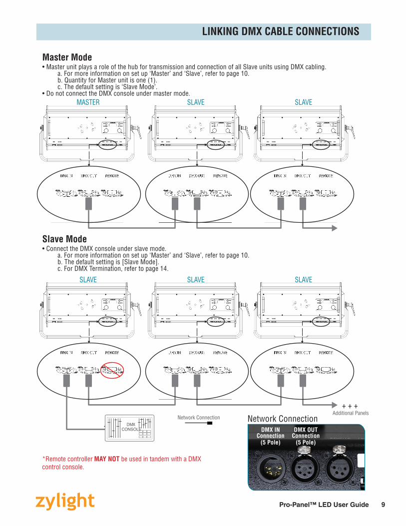
*Remote controller MAY NOT be used in tandem with a DMX control console.
DMXCONSOLE DMX IN
Connection(5 Pole)
DMX OUTConnection
(5 Pole)
Master Mode• Master unit plays a role of the hub for transmission and connection of all Slave units using DMX cabling. a. For more information on set up ‘Master’ and ‘Slave’, refer to page 10. b. Quantity for Master unit is one (1). c. The default setting is ‘Slave Mode’.• Do not connect the DMX console under master mode.
Slave Mode• Connect the DMX console under slave mode. a. For more information on set up ‘Master’ and ‘Slave’, refer to page 10. b. The default setting is [Slave Mode]. c. For DMX Termination, refer to page 14.
MASTER
SLAVE
SLAVE
SLAVE
SLAVE
SLAVE
Network Connection
LINKING DMX CABLE CONNECTIONS

10 Pro-Panel™ LED User Guide
1
1
1
2
2) Then PRESS the ‘ADDRESS’, ‘TUNGSTEN’, or ‘DAYLIGHT’ to toggle between ‘MSTR’ or ‘SLVE’.
1 2 33
1) PRESS the ‘TUNGSTEN’ then ‘ADDRESS’ button for 3 seconds until ‘MSTR’ or ‘SLVE’ (depending on previous setting) is displayed on the LED display.
1 22
3) To set, PRESS the ‘ON / OFF’ button.1
SETTING UP MASTER OR SLAVE
DMX 512 Input / Output Pin Map • Position the barn doors alongside the extruded edge of the fixture. • Align the thumbscrews with the adjustable receptacle holes in the fixture and insert into place. • Lock the barn doors by turning the silver thumbscrew.
DMX InputConnector
(5-Pin)
DMX OutputConnector
(5-Pin)
DMX 512 Connections DMX 512 Signal XLR PIN GND 1
DMX - 2
DMX 2 3
NOTE: Remaining pins are not used.
DMX Data Jump Cable XLR PIN SIGNAL COLOR 1 GND Yellow 2 DATA 1- Black 3 DATA 1+ White 4 DATA 2- Green 4 DATA 2+ Red
NOTE: Shield - Blue
CONNECTING TO THE DMX 512 NETWORK
How to set up an Address STEP 1: Press Address selection button and check the current address number. (Green color indicator is displayed) STEP 2: Press Address selection button again then will be flashing the current address number. (Red color indicator is displayed, address adjustment mode is active) STEP 3: Rotate Kelvin Selection Knob button and select the desired address number. STEP 4: Press Address selection button to save the modified number. (Green color indicator is displayed) STEP 5: Make changes as desired. Note: Valid address from ‘0~511’ To regain manual control
with the DMX cable plugged in, set the DMX address to ‘0’.Channel Layout: 1=Color 2=Dimming

11Pro-Panel™ LED User Guide
DMX vs DIMMING TABLE DMX vs KELVIN TABLEDMX Dimming[%] DMX Dimming[%] DMX Dimming[%] DMX Dimming[%] DMX Kelvin[K] DMX Kelvin[K] DMX Kelvin[K] DMX Kelvin[K]
0 0 66 26.3 130 51.3 193 76.3 0 2700 66 3700 130 4650 193 5600
1 1.3 67 131 194 1 2750 67 131 194
2 68 132 195 2 68 132 195
3 69 27.6 133 52.6 196 3 69 3750 133 4700 196
4 70 134 197 77.6 4 70 134 197 5650
5 71 135 198 5 71 135 198
6 2.6 72 136 53.9 199 6 2800 72 136 4750 199
7 73 28.9 137 200 78.9 7 73 3800 137 200 5700
8 74 138 201 8 74 138 201
9 3.9 75 139 202 9 2850 75 139 202
10 76 30.2 140 55.2 203 80.2 10 76 3850 140 4800 203 5750
11 77 141 204 11 77 141 204
12 5.2 78 142 205 12 2900 78 142 205
13 79 31.5 143 56.5 206 13 79 3900 143 4850 206
14 80 144 207 81.5 14 80 144 207 5800
15 81 145 208 15 81 145 208
16 6.5 82 146 57.8 209 16 2950 82 146 4900 209
17 83 32.8 147 210 82.8 17 83 3950 147 210 5850
18 84 148 211 18 84 148 211
19 7.8 85 149 212 19 3000 85 149 212
20 86 34.2 150 59.2 213 20 86 4000 150 4950 213
21 87 151 214 84.2 21 87 151 214 5900
22 9.2 88 152 215 22 3050 88 152 215
23 89 35.5 153 60.5 216 23 89 4050 153 5000 216
24 90 154 217 85.5 24 90 154 217 5950
25 91 155 218 25 91 155 218
26 10.5 92 156 219 26 3100 92 156 219
27 93 36.8 157 61.8 220 86.8 27 93 4100 157 5050 220 6000
28 94 158 221 28 94 158 221
29 11.8 95 159 222 29 3150 95 159 222
30 96 38.1 160 63.1 223 30 96 4150 160 5100 223
31 97 161 224 88.1 31 97 161 224 6050
32 13.1 98 162 225 32 3200 98 162 225
33 99 39.4 163 64.4 226 33 99 4200 163 5150 226
34 100 164 227 89.4 34 100 164 227 6100
35 101 165 228 35 101 165 228
36 14.4 102 166 229 36 3250 102 166 229
37 103 40.7 167 65.7 230 90.7 37 103 4250 167 5200 230 6150
38 104 168 231 38 104 168 231
39 15.7 105 169 232 39 3300 105 169 232
40 106 42.1 170 67.1 233 40 106 4300 170 5250 233
41 107 171 234 92.1 41 107 171 234 6200
42 17.1 108 172 235 42 3350 108 172 235
43 109 173 68.4 236 43 109 173 5300 236
44 110 43.4 174 237 93.4 44 110 4350 174 237 6250
45 111 175 238 45 111 175 238
46 18.4 112 176 239 46 3400 112 176 239
47 113 44.7 177 69.7 240 94.7 47 113 4400 177 5350 240 6300
48 114 178 241 48 114 178 241
49 19.7 115 179 242 49 3450 115 179 242
50 116 46 180 71 243 50 116 4450 180 5400 243
51 117 181 244 96 51 117 181 244 6350
52 118 182 245 52 118 182 245
53 21 119 183 72.3 246 53 3500 119 183 5450 246
54 120 47.3 184 247 97.3 54 120 4500 184 247 6400
55 121 185 248 55 121 185 248
56 22.3 122 186 249 56 3550 122 186 249
57 123 48.6 187 73.6 250 98.6 57 123 4550 187 5500 250 6450
58 124 188 251 58 124 188 251
59 23.6 125 189 252 59 3600 125 189 252
60 126 50 190 75 253 60 126 4600 190 5550 253
61 127 191 254 100 61 127 191 254 6500
62 128 192 255 62 128 192 255
63 25 129 63 3650 129
64 64
65 65
12 Pro-Panel™ LED User Guide
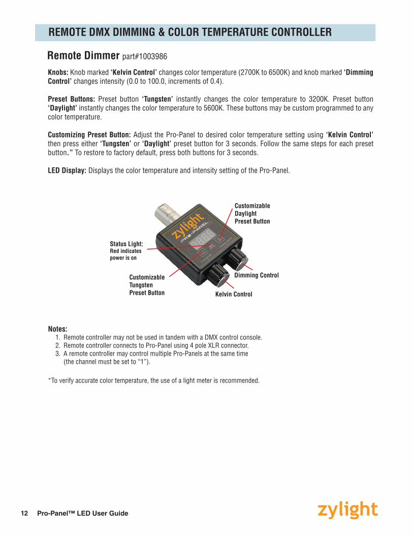
Remote Dimmer part#1003986
Knobs: Knob marked ‘Kelvin Control’ changes color temperature (2700K to 6500K) and knob marked ‘Dimming Control’ changes intensity (0.0 to 100.0, increments of 0.4).
Preset Buttons: Preset button ‘Tungsten’ instantly changes the color temperature to 3200K. Preset button ‘Daylight’ instantly changes the color temperature to 5600K. These buttons may be custom programmed to any color temperature.
Customizing Preset Button: Adjust the Pro-Panel to desired color temperature setting using ‘Kelvin Control’ then press either ‘Tungsten’ or ‘Daylight’ preset button for 3 seconds. Follow the same steps for each preset button.” To restore to factory default, press both buttons for 3 seconds.
LED Display: Displays the color temperature and intensity setting of the Pro-Panel.
Notes: 1. Remote controller may not be used in tandem with a DMX control console. 2. Remote controller connects to Pro-Panel using 4 pole XLR connector. 3. A remote controller may control multiple Pro-Panels at the same time (the channel must be set to “1”).
*To verify accurate color temperature, the use of a light meter is recommended.
Kelvin Control
Status Light:Red indicates power is on
CustomizableTungstenPreset Button
Dimming Control
CustomizableDaylightPreset Button
REMOTE DMX DIMMING & COLOR TEMPERATURE CONTROLLER
13Pro-Panel™ LED User Guide
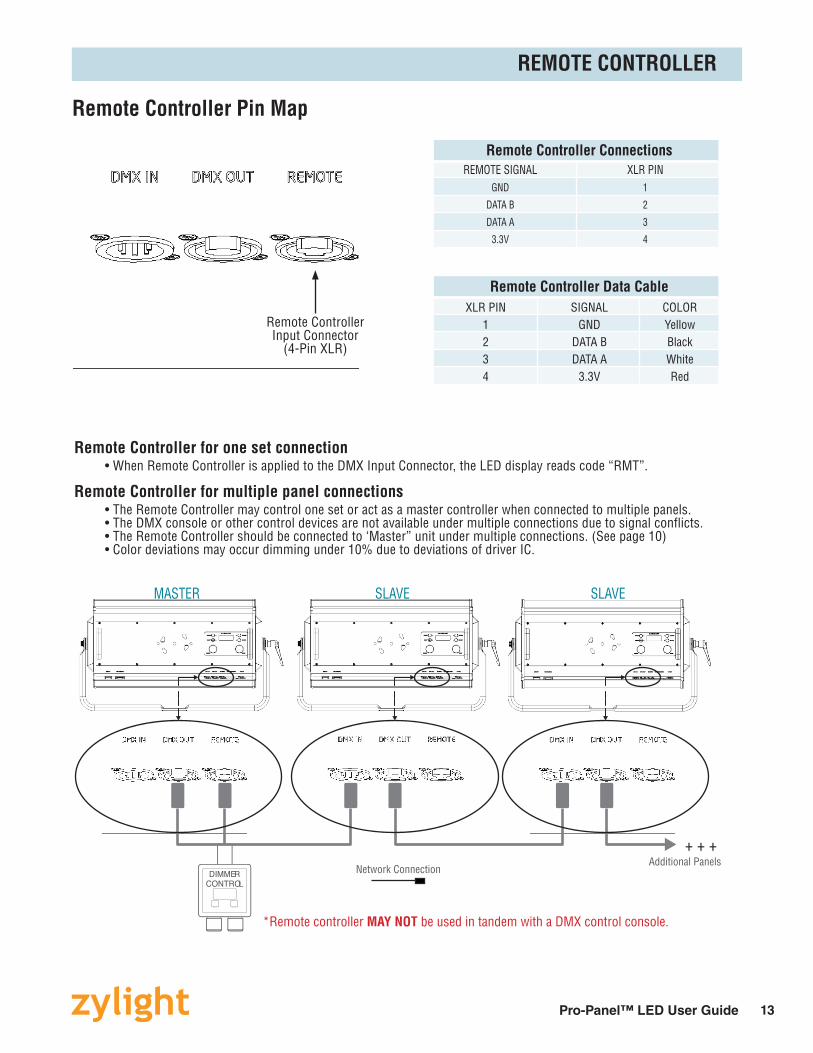
Remote Controller Pin Map
Remote Controller for one set connection • When Remote Controller is applied to the DMX Input Connector, the LED display reads code “RMT”.
Remote Controller for multiple panel connections • The Remote Controller may control one set or act as a master controller when connected to multiple panels. • The DMX console or other control devices are not available under multiple connections due to signal conflicts. • The Remote Controller should be connected to ‘Master” unit under multiple connections. (See page 10) • Color deviations may occur dimming under 10% due to deviations of driver IC.
Additional Panels+ + +
Network Connection
*Remote controller MAY NOT be used in tandem with a DMX control console.
DIMMERCONTROL
MASTER SLAVE SLAVE
Remote Controller Connections REMOTE SIGNAL XLR PIN GND 1
DATA B 2
DATA A 3
3.3V 4
Remote Controller Data Cable XLR PIN SIGNAL COLOR 1 GND Yellow 2 DATA B Black 3 DATA A White 4 3.3V Red
Remote Controller Input Connector
(4-Pin XLR)
REMOTE CONTROLLER
14 Pro-Panel™ LED User Guide
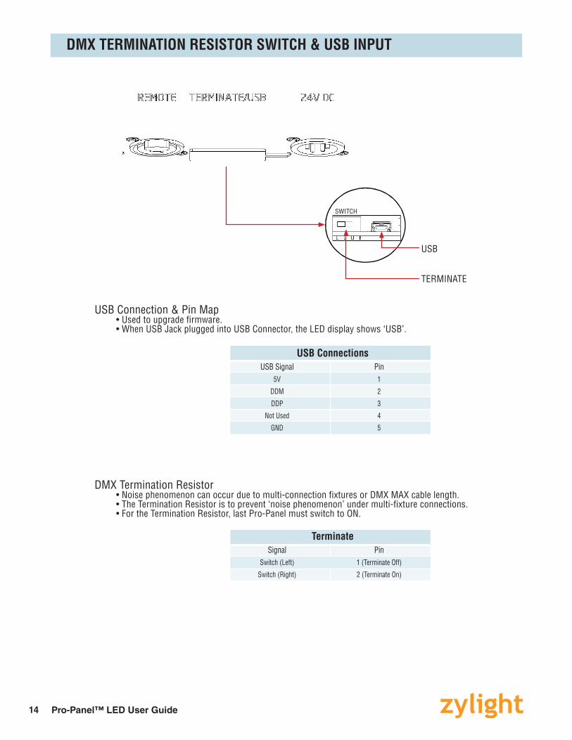
SWITCH
TERMINATE
USB
USB ConnectionsUSB Signal Pin
5V 1
DDM 2
DDP 3
Not Used 4
GND 5
DMX Termination Resistor• Noise phenomenon can occur due to multi-connection fixtures or DMX MAX cable length.• The Termination Resistor is to prevent ‘noise phenomenon’ under multi-fixture connections.• For the Termination Resistor, last Pro-Panel must switch to ON.
USB Connection & Pin Map• Used to upgrade firmware.• When USB Jack plugged into USB Connector, the LED display shows ‘USB’.
TerminateSignal Pin
Switch (Left) 1 (Terminate Off)
Switch (Right) 2 (Terminate On)
DMX TERMINATION RESISTOR SWITCH & USB INPUT
15Pro-Panel™ LED User Guide
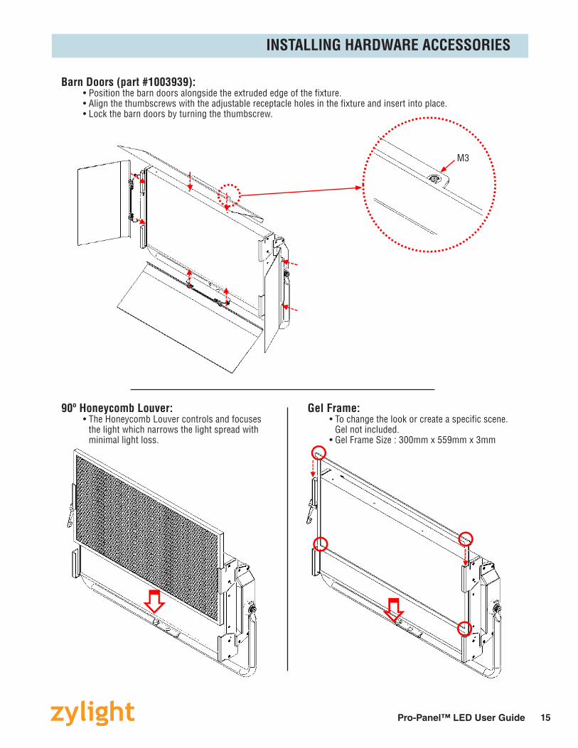
Barn Doors (part #1003939): • Position the barn doors alongside the extruded edge of the fixture. • Align the thumbscrews with the adjustable receptacle holes in the fixture and insert into place. • Lock the barn doors by turning the thumbscrew.
Gel Frame: • To change the look or create a specific scene. Gel not included. • Gel Frame Size : 300mm x 559mm x 3mm
90º Honeycomb Louver: • The Honeycomb Louver controls and focuses the light which narrows the light spread with minimal light loss.
INSTALLING HARDWARE ACCESSORIES
M3

16 Pro-Panel™ LED User GuideM-PPLEDV2/1116
ZYLIGHT LLC10718 McCUNE AVENUE, LOS ANGELES, CA 90034T. (978) [email protected]
Scan with a smartphoneto view Pro-Panel online.