Embed Size (px)
Citation preview

Subscriber access provided by Imperial College London | Library
ACS Applied Materials & Interfaces is published by the American Chemical Society.1155 Sixteenth Street N.W., Washington, DC 20036Published by American Chemical Society. Copyright © American Chemical Society.However, no copyright claim is made to original U.S. Government works, or worksproduced by employees of any Commonwealth realm Crown government in the courseof their duties.
Article
Property and Shape Modulation of Carbon Fibers Using LasersJonny J. Blaker, David Benbow Anthony, Guang Tang, Siti-Ros Shamsuddin, Gerhard Kalinka,
Malte Weinrich, Amin Abdolvand, Milo Sebastian Peter Shaffer, and Alexander BismarckACS Appl. Mater. Interfaces, Just Accepted Manuscript • DOI: 10.1021/acsami.6b05228 • Publication Date (Web): 26 May 2016
Downloaded from http://pubs.acs.org on June 7, 2016
Just Accepted
“Just Accepted” manuscripts have been peer-reviewed and accepted for publication. They are postedonline prior to technical editing, formatting for publication and author proofing. The American ChemicalSociety provides “Just Accepted” as a free service to the research community to expedite thedissemination of scientific material as soon as possible after acceptance. “Just Accepted” manuscriptsappear in full in PDF format accompanied by an HTML abstract. “Just Accepted” manuscripts have beenfully peer reviewed, but should not be considered the official version of record. They are accessible to allreaders and citable by the Digital Object Identifier (DOI®). “Just Accepted” is an optional service offeredto authors. Therefore, the “Just Accepted” Web site may not include all articles that will be publishedin the journal. After a manuscript is technically edited and formatted, it will be removed from the “JustAccepted” Web site and published as an ASAP article. Note that technical editing may introduce minorchanges to the manuscript text and/or graphics which could affect content, and all legal disclaimersand ethical guidelines that apply to the journal pertain. ACS cannot be held responsible for errorsor consequences arising from the use of information contained in these “Just Accepted” manuscripts.

1
Property and Shape Modulation of Carbon Fibers Using Lasers
Jonny J. Blaker1*
, David B. Anthony2,3
, Guang Tang4, Siti-Ros Shamsuddin
3, Gerhard
Kalinka5, Malte Weinrich
5, Amin Abdolvand
4, Milo S. P. Shaffer
2 and Alexander
Bismarck3,6
1 Bio-/Active Materials Group, School of Materials, MSS Tower, The University of
Manchester, M13 9PL, UK
2 Nanostructured Hierarchical Assemblies and Composites Group (NanoHAC),
Department of Chemistry, Imperial College London, South Kensington Campus,
London, SW7 2AZ, UK
3 Polymer and Composite Engineering (PaCE) Group, Department of Chemical
Engineering, Imperial College London, South Kensington Campus, London, SW7
2AZ, UK
4 Materials & Photonics Systems (MAPS) Group, School of Engineering, Physics and
Mathematics, University of Dundee, Dundee, DD1 4HN, UK
5 BAM Federal Institute for Materials Research and Testing, Berlin, Germany
6 Polymer and Composite Engineering (PaCE) Group, Institute of Materials
Chemistry and Research, Faculty of Chemistry, University of Vienna, Währinger Str.
42, A-1090 Vienna, Austria
Corresponding Author
*Email: [email protected]
Page 1 of 26
ACS Paragon Plus Environment
ACS Applied Materials & Interfaces
123456789101112131415161718192021222324252627282930313233343536373839404142434445464748495051525354555657585960

2
Abstract
An exciting challenge is to create unduloid-reinforcing fibers with tailored
dimensions to produce synthetic composites with improved toughness and increased
ductility. Continuous carbon fibers, the state-of-the-art reinforcement for structural
composites, were modified via controlled laser irradiation to result in expanded
outwardly tapered regions, as well as fibers with Q-tip (cotton-bud) end shapes. A
pulsed laser treatment was used to introduce damage at the single carbon fiber level,
creating expanded regions at predetermined points along the lengths of continuous
carbon fibers, whilst maintaining much of their stiffness. The range of produced
shapes was quantified and correlated to single fiber tensile properties. Mapped Raman
spectroscopy was used to elucidate the local compositional and structural changes.
Irradiation conditions were adjusted to create a swollen weakened region, such that
fiber failure occurred in the laser treated region producing two fiber ends with
outwardly tapered ends. Upon loading the tapered fibers allow for viscoelastic energy
dissipation during fiber pull-out by enhanced friction as the fibers plough through a
matrix. In these tapered fibers, diameters were locally increased up to 53%, forming
outward taper angles of up to 1.8°. The tensile strength and strain to failure of the
modified fibers were significantly reduced, by 75% and 55%, respectively, ensuring
localization of the break in the expanded region; however, the fiber stiffness was only
reduced by 17%. Using harsher irradiation conditions, carbon fibers were completely
cut, resulting in cotton-bud fiber end shapes. Single fiber pull-out tests performed
using these fibers revealed a 6.75 fold increase in work of pull-out compared to
pristine carbon fibers. Controlled laser irradiation is a route to modify the shape of
continuous carbon fibers along their lengths, as well as to cut them into controlled
lengths leaving tapered or cotton-bud shapes.
Page 2 of 26
ACS Paragon Plus Environment
ACS Applied Materials & Interfaces
123456789101112131415161718192021222324252627282930313233343536373839404142434445464748495051525354555657585960

3
1. Introduction
It remains challenging to produce unduloid carbon fibers, which can be expected to
result in an increased pull out work, hopefully to realize new composites. The
outward tapering and geometric dovetailing motifs observed in the reinforcement
phase of nacre1-3
have been successfully implemented in macro-composites4 and more
recently to 3 mm diameter short steel fibers with machined conical ends.5 Fiber pull-
out tests of these steel fibers from an epoxy matrix demonstrated that fibers with an
taper angle of 5° dissipated up to 27 times more energy than straight fibers, whereas
larger angles induced premature matrix failure.5A significant enhancement in work of
pull-out and maximum pull-out force was also observed at 2° (circa 20 fold
improvement).5 The size of the enlarged fiber ends can alter the residual stress state
producing either tensile or compressive tractions at the fiber interface.6 Well-designed
composites can undergo multiple fracture events, spreading fiber/matrix debonding
and fiber pull-out across large volumes, allowing significant deformation before a
crack localizes and the composite fails.7 Tapered fibers can bridge cracks and plough
through the matrix, contributing to viscoplastic energy dissipation. There is a growing
body of evidence from synthetic composite materials,6,8-12
which shows that suitably
bulbous/tapered fiber ends and wavy fibers13,14
can act to increase the work of pull-
out, delocalize inelastic deformation and induce strain-hardening. Fabrication routes
include thermal deformation, as applied to thermoplastic UHMWPE (Dyneema™)
fibers,8 fiber knotting,
9 and mechanical deformation to result in wavy or flat-ended
fibers.9-12
It is a significant challenge to transpose outward tapering features and an
unduloid fiber shape to continuous carbon fibers, the preferred reinforcements in high
performance composites, with typical diameters in the range 5-10 µm. Short ‘cotton-
bud’ carbon fibers might be applied as short fiber reinforcements. More ideally, the
Page 3 of 26
ACS Paragon Plus Environment
ACS Applied Materials & Interfaces
123456789101112131415161718192021222324252627282930313233343536373839404142434445464748495051525354555657585960
4
fibers would break, in situ, to form the tapered segments, since continuous fibers can
be more readily processed into high loading fraction, aligned composites and would
provide higher initial stiffness.
Lasers are being increasingly applied to cut holes and shapes into high performance
unidirectional (UD) carbon fiber composites,15-21
as well as to perforate laminates,
cutting fibers at predefined points to produce highly aligned discontinuous composites
mainly with the aim to improve manufacturing ductility.22,23
Carbon fibers cut via
laser ablation have been reported to feature expanded ends (up to 60%) in the vicinity
of the heat-affected zones of such laser-drilled holes.17,22-24
This local expansion has
been attributed to irreversible changes in the arrangements of the basal planes, caused
by rapid heating and steep thermal gradients occurring during laser cutting, volatising
non-carbon impurities within the structure of the fibers.15,16
Controlled laser
irradiation therefore presents an opportunity to modify the shape of continuous carbon
fibers along their lengths.
The current work systematically investigates the effect of laser treatment on single
carbon fibers to produce i) continuous fibers with expanded regions, ii) continuous
fibers with expanded and ablated (necked) regions, and iii) ablated fibers with
expanded, i.e. cotton-bud shaped, fiber ends. The mechanical properties of the treated
continuous fibers are evaluated by single fiber tensile testing and their failure points
assessed post-mortem. Laser mapping Raman spectroscopy is used to elucidate
compositional and structural changes due to laser irradiation. The pull-out response of
the ablated, cotton-bud end fibers is investigated by single fiber pull-out tests.
Page 4 of 26
ACS Paragon Plus Environment
ACS Applied Materials & Interfaces
123456789101112131415161718192021222324252627282930313233343536373839404142434445464748495051525354555657585960
5
2. Experimental section
2.1 Materials
Unsized, polyacrylonitrile (PAN) based AS4 carbon fibers were kindly provided by
Hexcel Ltd. (Cambridge, UK). According to the manufacturer the AS4 fibers have a
carbon content of 94%, tensile modulus of 230 GPa, tensile strength 4430 MPa, and
elongation at break of 1.8%. Two-part epoxy adhesive, Araldite®
Rapid Adhesive was
used to glue single carbon fibers to paper frames, which acted as temporary supports
for testing. The conductive paint used for scanning electron microscopy (SEM) was
Acheson Silver DAG 1415 M (Agar Scientific, UK). The matrix material chosen for
single fiber pull-out tests was a two-component pourable transparent silicone rubber,
Elastosil®
LR 7665 A/B (Wacker Chemie AG, München, Germany). Elemental
analysis performed on unsized AS4 fibers confirmed that the fibers have a carbon
content of 94.72%, with nitrogen, oxygen, hydrogen and sulphur contents of 4.62%,
0.2%, 0.12% and <0.02%, respectively.
2.2 Carbon fiber mounting for laser irradiation
Single fibers were individually fixed on white paper frames (80 gsm) using epoxy
adhesive and end-tabbed with paper. These frames allowed for positioning and
handling of the fibers for laser irradiation (depicted in Figure 1) as well as scanning
electron microscope (SEM) evaluation, Raman spectroscopy, single fiber tensile
testing (gauge length 20 mm) and post-failure SEM analysis. Small scalpel cuts were
made on the paper frames in line with the centre of the gauge length, serving as
guides to position the fibers for irradiation and location of the modified region for
SEM and Raman spectroscopy.
Page 5 of 26
ACS Paragon Plus Environment
ACS Applied Materials & Interfaces
123456789101112131415161718192021222324252627282930313233343536373839404142434445464748495051525354555657585960
6
2.3 Laser irradiation to effect fiber shape change and local weakening
Frames containing the fibers were mounted on anodized aluminium substrates using
thin strips of 3M magic tape to maintain the fibers flat. The substrates were positioned
underneath the laser beam, such that the laser guide path would run vertically through
the length of a single column, to irradiate through the mid section of 10 fibers at a
time. A nanosecond (8 ns) pulsed Nd: YVO4 laser with a maximum average power
of 17.5 W at λ = 1064 nm was operated with parameters in the range of 1.1 - 17.5 W
of average power, a repetition rate in the range of 50 - 100 kHz and beam scanning
speeds in the range of 50 - 200 mm s-1
. The laser beam was focused to a spot size of ~
70 µm in diameter on the target. The laser had a Gaussian profile and the focal point
was set to the height of the substrate in an effort to irradiate all fibers equally. Laser
conditions were adjusted and resulted in three different fiber shapes (Figure 1),
causing: i) local expansion of the fiber at the irradiation site; ii) expansion and
ablation of the fibers, and iii) expansion and cutting of the fibers. These fiber classes
are called Expanded, Expanded/Ablated and Cotton-bud end fibers, respectively
(Figure 1). Laser parameters 1.1 W of average output power, frequency 100 kHz, and
speed 100 mm s-1
resulted in ca. 20% of fibers being cut; at 17.5 W, frequency 50
kHz and speed 50 mm s-1
all fibers were cut. Parameters 1.1 W, frequency 100 kHz
and speed 200 mm s-1
consistently resulted in intact fibers. Immediately post
irradiation, the fibers were investigated using a digital microscope surface profiling
system (KEYENCE VHX-1000) to confirm the effect of irradiation conditions on fiber
morphology and fiber cutting. The laser operated at 1.1 W of average power had an
energy fluence of 0.3 J cm-2
(energy per pulse 11 µJ). The laser fired 35 pules per
spot, since the laser was run at 100 kHz and speed 200 mm s-1
. 1D temperature
modelling has been conducted for this condition. A rough estimate shows that the
Page 6 of 26
ACS Paragon Plus Environment
ACS Applied Materials & Interfaces
123456789101112131415161718192021222324252627282930313233343536373839404142434445464748495051525354555657585960
7
temperature rise in the focus of the beam during the processing is in excess of 2900 K.
The vaporisation temperature of PAN-based carbon fibers is reported15
to be 3500 K
and the axial thermal conductivity 6.83 W m-1
K-1
, as reported by the manufacturer.
For the same average power, when lower scanning speeds, such as 100 mm s-1
or 50
mm s-1
, were used there are 70 and 140 pulses per spot, respectively, leading to
cutting of the fibers. When higher average powers were used (17.5 W) the fibers were
also cut due to temperature in excess of carbon vaporization. The effect of laser
treatment on the mechanical properties of Expanded and Expanded/Ablated fibers,
compared to Control carbon fibers was assessed via single fiber tensile testing. Single
fiber pull-out tests were conducted on Cotton-bud end carbon fibers to assess
enhancement of pull-out behaviour due to shape modification in comparison to
control carbon fibers.
2.4 Quantification of fiber shape modification
SEM was conducted on individual irradiated and control fibers mounted in paper
frames using a JEOL 5160 LV SEM (Jeol Ltd., Japan). The end tab region of the
paper frames were attached to SEM stubs via adhesive carbon tabs. A small amount
of conductive silver paint was added to the end of the tab, to connect the carbon fiber
to the holder. Care was taken not to allow the carbon fibers to directly touch the
adhesive carbon tab in order to keep the fibers in tact. This technique allowed the
same irradiated fiber to be imaged prior and post tensile testing to assess the fiber
shape after irradiation/ablation and to determine the failure point, respectively. A
scalpel blade was used to carefully remove the paper templates from the adhesive
carbon tab ahead of tensile testing. The software ImageJ (Version 1.48, NIH, USA)
was used to quantify fiber shape modification (Figure 1). The affected length is
Page 7 of 26
ACS Paragon Plus Environment
ACS Applied Materials & Interfaces
123456789101112131415161718192021222324252627282930313233343536373839404142434445464748495051525354555657585960
8
defined here as the region with a diameter in excess of 0.1 µm of the unaffected
region. The apparent taper angle θ of the expanded fibers was determined using
Equation 1:
� = tan�1 (������0)
2 Equation 1
where �� � is the maximum expanded diameter, �� the fiber diameter of the
unaffected region, and � the affected length (θ represents the angle formed at one side
of the fiber only). Irradiated regions were also investigated using high-resolution field
emission gun scanning electron microscope (FEG-SEM) (Leo Gemini 1525 using
SmartSEM software interface V05.05.03.00, 2010, Carl Zeiss NTS Ltd., UK).
Quantitative measurements are based on 30 fibers with standard errors provided.
2.5 Single fiber tensile testing
Expanded and Expanded/Ablated single carbon fibers were tensile tested at 21 °C
with a crosshead speed of 15 µm s-1
following BS ISO 11566:1996 using a TST 350
tensile testing rig (Linkam Scientific Instrument Ltd., UK) equipped with a 20 N load
cell. The paper end tabs were gripped in the machine and then the lateral parts of the
frames cut through using fine scissors allowing the fiber to be loaded. The
displacement and load were recorded, and later converted to stress and strain. Tensile
tests were conducted on a group of 30 carbon fibers.
2.6 Raman spectroscopy of control and ablated fiber regions
Raman spectroscopy provides a non-destructive method of probing global properties
of graphitic carbon materials by determining the D mode (1350 cm-1
), G mode (1582
Page 8 of 26
ACS Paragon Plus Environment
ACS Applied Materials & Interfaces
123456789101112131415161718192021222324252627282930313233343536373839404142434445464748495051525354555657585960
9
cm-1
) and 2D mode (2700 cm-1
, overtone of the D mode).25
Raman spectra were
measured using a LabRAM Infinity system with 532 nm (2.33 eV) Nd-YAG green
laser (numerical aperture (NA) 0.55/50x, maximum power 24 mW, LabSpec V4.18-
06 2005 software interface, Horiba Jobin Yvon Ltd., UK) and on a Renishaw inVia
micro-Raman spectrometer with 532 nm (2.33 eV) DPSS diode (NA 0.8/100x, sample
power 3.2 mW, WiRE 4.1 HF7241 software 2014 interface, Renishaw PLC, UK) in
backscattered geometry, with relative laser spot diameters 1.2 µm and 0.8 µm
respectively, with a spatial resolution of ca. 1 µm in each system. Raman spectra
were processed and Raman maps produced using WiRE software using spectra
that were background subtracted and normalized with respect to the G mode.
Intensity ratio maps for D mode/G mode (ID/IG) and 2D mode/G mode (I2D/IG)
were sampled from 5-95% of total binned data to remove extremities and
undesired weighting towards noise, which becomes significant. Raman ID/IG
ratio and I2D/IG ratio intensity maps are also shown with a black mask to better
display ratios since, outside the fiber cross-section noise dominated; the masks
were generated from intensity D mode (ID) maps, which accurately matched the
optical images. Relative intensity G mode maps are normalised and are shown
without masks.
2.7 Single fiber pull-out testing
The apparent interfacial shear strength (τIFSS) and the work of pull-out were
determined using single fiber pull-out tests. τIFSS is a measure of ‘practical’ adhesion
between the fiber and matrix. In this test, a special transparent glass chamber was
used to hold the matrix material. The fiber was attached to a steel screw using
cyanoacrylate adhesive. The matrix used was Elastosil®
LR 7665 A/B (Wacker), a
Page 9 of 26
ACS Paragon Plus Environment
ACS Applied Materials & Interfaces
123456789101112131415161718192021222324252627282930313233343536373839404142434445464748495051525354555657585960
10
pourable, two-component compound liquid silicone rubber. The mixed uncured
matrix was then poured into the glass chamber and the fiber embedded slowly into the
matrix to an embedded length of ~200 µm. The matrix was then cured at 45 °C for
10 h in an oven, then removed and cooled to ambient temperature. Fiber pull-out tests
were performed using a piezo-motor fixed on a stiff frame to avoid energy storage in
the free fiber length between the matrix surface and clamping device. The fiber was
loaded at a speed of 5 µm s-1
and pulled out of the matrix while the force was
recorded throughout the experiment by a load cell. τIFSS was calculated from FMAX
required to trigger de-bonding of the embedded carbon fiber from the matrix using
Equation 2:
����� =����
��� Equation 2
where df is the fiber diameter and L the embedded fiber length (determined from the
load-displacement curves). The work of pull-out was determined by the area under the
load-displacement curve. During the fiber pull-out process, images were captured
using an optical microscope (Axionplan Zeiss equipped with an Axiocam ICc3
camera (Carl Zeiss Microscopy GmbH, Germany)) to assess the pull-out
characteristics of the fibers with modified ends from the surrounding matrix.26
Difficulties in sample preparation lead to only 5 control samples and 3 Cotton-bud
end fibers being tested.
3. Results and Discussion
3.1 Effect of laser irradiation on fiber morphology and shape
Page 10 of 26
ACS Paragon Plus Environment
ACS Applied Materials & Interfaces
123456789101112131415161718192021222324252627282930313233343536373839404142434445464748495051525354555657585960

11
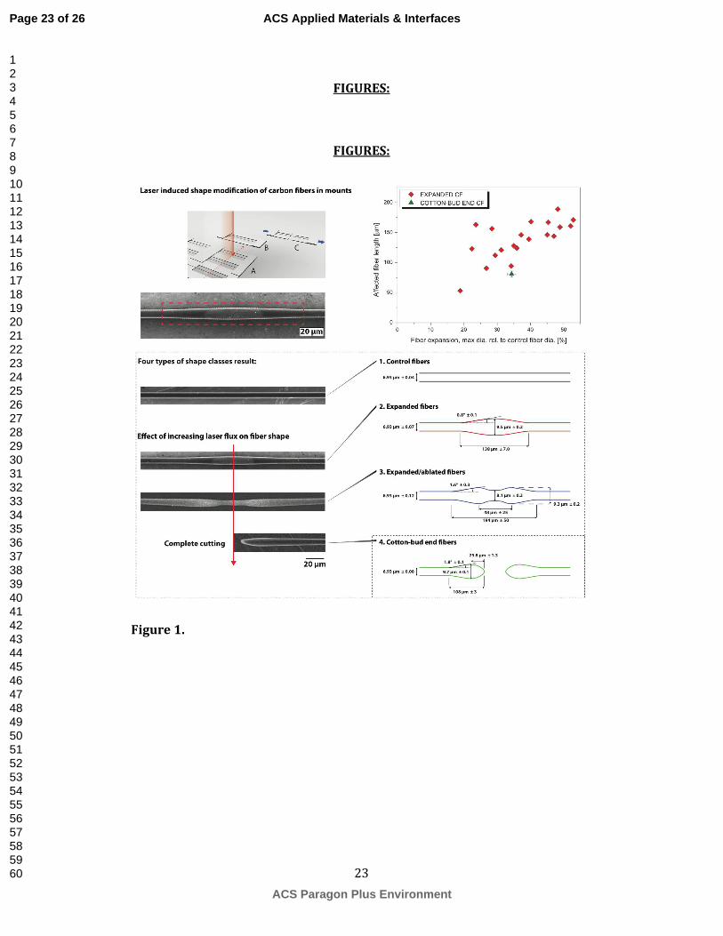
The laser treated fibers consistently exhibited an affected region along their length,
consistent with a single pass of the laser. Three resulting fiber classes (Expanded,
Expanded/Ablated and Cotton-bud end) were obtained depending on the focal point
of the laser (Figure 1). The diameter of laser treated fibers increased from 7.0 µm, i.e.
the average diameter of the control fibers, to a maximum of 9.7 µm, corresponding to
an increase of 37% (Expanded fibers). The average affected length of these Expanded
carbon fibers after a single laser pass was ~140 µm, resulting in a taper angle ~ 1°.
Expanded/Ablated fibers exhibited slightly larger affected lengths with narrowed
midsections, flanked by expanded regions, with taper angles of 1.6°. Cotton-bud end
fibers were completely cut (ablated) through and had average affected lengths of 108
µm with taper angles of 1.8° (as detailed in Figure 1). The maximum expansion
observed was 53%, after which ablation reduced the expanded fiber diameter,
eventually cutting the fiber, resulting in characteristic Cotton-bud shaped fiber ends.
This expansion value is comparable to those observed for PAN-based (T300) fibers in
the perimeter of laser-drilled holes.16
Voisey et al.16
established that swelling up to
60% occurred when laser drilling low modulus T300 fibers, embedded in a PEEK
matrix.17
Interestingly, carbon fibers containing fewer impurities (higher C contents)
were reported to be apparently less susceptible to laser-induced expansion in the
perimeter of laser-drilled holes.16
3.2 Effect of laser ablation on fiber tensile properties
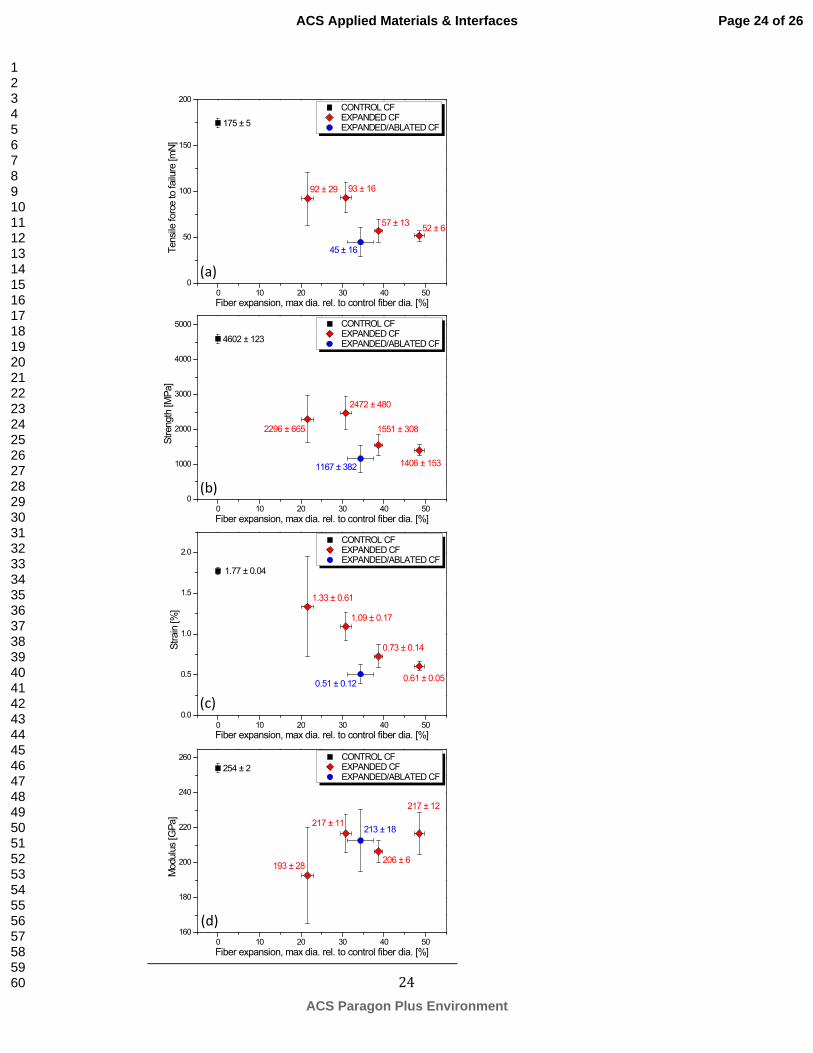
The tensile properties of Expanded and Expanded/Ablated carbon fibers were
significantly reduced in comparison to control AS4 fibers (Figure 2 (a-d)). All fibers
exhibited a linear elastic behaviour with brittle fracture. The control carbon fibers
failed catastrophically, breaking into fragments, whereas the laser treated fibers broke
Page 11 of 26
ACS Paragon Plus Environment
ACS Applied Materials & Interfaces
123456789101112131415161718192021222324252627282930313233343536373839404142434445464748495051525354555657585960
12
into two, at their pre-defined weak point (expanded or ablated regions) resulting in
outwardly tapered fiber ends (Figure 3) (for an Expanded carbon fiber). The fiber
tensile strength (Figure 2 (b)) was significantly reduced at the laser-treated location,
by ~69% for Expanded fibers, and 75% for Expanded/Ablated fibers. Modulus of
laser treated fibers (Figure 2 (c)) were modestly reduced, by ca. 17% (averaged over
all treated fibers) in comparison to the control fibers. The tensile strength and stiffness
were calculated based on the cross-section of the original unmodified fiber, partly as
not all the failed fiber ends could be recovered after testing but also because the
relative performance compared to the original fiber is both easier to understand and
more relevant to subsequent composite performance. Strain to failure of the laser
treated fibers was significantly reduced, in line with the strength, (Figure 2 (d)) from
1.8% (Control fibers) to 0.6% (Expanded fibers), and 0.5% for Expanded/Ablated
fibers. Whilst the local reduction in strength is quite significant, the effect is useful in
the correct context. The fibers retain sufficient strength to be handled and potentially
processed into high loading fraction composites, and the stiffness is broadly retained.
A significant reduction in strength is, in fact, needed to localise the failure reliably at
the desired, shaped location. Whilst the strength reduction is greater than required, the
distribution of pre-weakened points can be designed to minimise the reduction in
strength of the overall composite, by adjusting (proto)fragment aspect ratio and
distribution.
3.3 Raman spectroscopy and mapping of laser treated fibers
Raman analysis on the surface and in the interior (fracture surface) of the Control,
Expanded and Expanded/Ablated carbon fiber morphologies provides information
about the local degree of crystallinity (Figure 4 (a-f)). The Raman spectra of the
Page 12 of 26
ACS Paragon Plus Environment
ACS Applied Materials & Interfaces
123456789101112131415161718192021222324252627282930313233343536373839404142434445464748495051525354555657585960

13
Control carbon fiber were very consistent along the whole fiber length and across the
internal cross-section (Figure 4 (b) and (e)). The uniformity of relative IG, ID/IG ratio
and I2D/IG ratio can be clearly seen in individual Raman spectra (Figure 4 (e)) and
more vividly in the Raman maps (Figure 4 (f)). The cross-section of the Control
carbon fiber is regular and circular, typical for commercial grade carbon fibers. The
absence of the 2D mode in the as-received AS4 fiber, a mode related to the 2nd
order
phonon scattering, can be attributed to the relatively low carbonization and
graphitisation temperatures, c.a. 1300 °C, of PAN-derived high strength carbon
fibers.19
In the Expanded regions, the D and G modes sharpen and the 2D mode
emerges, becoming more intense along the fiber axis towards the irradiated region
(Figure 4 (a) and (b) from region 1 to 5). These changes indicate that the underlying
carbon structure of the carbon fiber is more crystalline in the irradiated zone.
Temperatures on the order of 2000 °C are easily achieved in laser irradiation (see
section 2.3), leading to reordering of carbon structure in the PAN fiber turbostratic
core. Raman maps of the Expanded fiber show an increased but comparatively
uniform ID/IG intensity ratio over the cross-section, suggesting that the whole fiber has
been modified in the irradiated region. Yet, the I2D/IG ratio in the cross-section
indicates that the outer shell is most graphitized, presumably as it is heated most
strongly (Figure 4 (f)). Although the remaining carbon is more graphitic, in the
Expanded regions, the fiber surfaces are damaged; showing roughened and pitted
morphology, with very slight increase in oxygen content (supplementary information,
Figure S1). Expanded/Ablated carbon fibers show a similar trend along the modified
region (Figure 4 (b)) flanked by regions, which were not laser irradiated. In the
ablated cross-section (‘C’), the graphitic shell is more obvious, consistent with the
development of higher temperatures. Expanded and Expanded/Ablated fibers show a
Page 13 of 26
ACS Paragon Plus Environment
ACS Applied Materials & Interfaces
123456789101112131415161718192021222324252627282930313233343536373839404142434445464748495051525354555657585960
14
distinctly non-circular cross-section attributed to the asymmetric laser illumination
(Figure 4 (d)). The Raman mapping shows that laser treated fibers exhibit alterations
to the core structure throughout the cross-section, as only hypothesized previously in
literature.16
It is clear that the tapered shape arises primarily from expansion and not
from deposition of a distinct phase. This mechanism is preferable in the current
context, as there is no weak interphase within the tapered region, which might lead to
a premature shear failure. It is preferable that the jamming/wedging loads on the fiber
end are transferred to the full fiber cross-section. As the cross-section increases, and
some material may be ablated, the density in the modified region must decrease; on
the other hand, the density of carbon should increase with increasing degree of
graphitization. Since no pores are observed by SEM, there must be an increase in
microporosity within the fiber due to thermal expansion/contraction effects and/or the
evolution of volatiles. Expanded and Expanded/Ablated fibers show a distinctly
non-circular cross-section understood to originate from the uneven modification
caused by laser irradiation, with one side of the fiber witnessing greater energy
absorption and subsequent expansion (or ablation) when compared to the non-
irradiated side (Figure 4 (d)). Irregular cross-sectional profiles of the irradiated
samples are unlikely to be a product of the single fiber tensile test, as carbon fibers
fail in a brittle catastrophic manner. The increased degree of graphitization of the
modified regions is consistent with the relative retention of stiffness but loss of
strength, as observed for carbon fibers in general as a function of graphitization
temperature; the presence of microporosity may magnify this trend.
3.4 Single fiber pull-out tests
Page 14 of 26
ACS Paragon Plus Environment
ACS Applied Materials & Interfaces
123456789101112131415161718192021222324252627282930313233343536373839404142434445464748495051525354555657585960
15
The pull-out behaviour of the cotton-bud terminated carbon fibers can be visualized
by single fiber tests in a transparent silicone rubber matrix (Figure 5 (a) and (b)).
Significant ploughing of the Cotton-bud end fibers through the matrix was evident
and disruption of the matrix observed (Figure 5 (b)); in contrast, the Control fibers
exhibited clean pull-out (Figure 5 (a)). The work of pull-out was found to increase
dramatically, ~7 fold for cotton-bud end fibers, compared to Control carbon fibers
(Figure 5 (c)). Normalized to embedded length this constitutes an improvement from
2.3 ± 0.6 µJ mm-1
for Control carbon fibers to 18.7 ± 3.6 µJ mm-1
for cotton-bud end
fibers. The apparent interfacial shear strength for cotton-bud fibers improved ~5-fold
compared to Control fibers. The intended wedging interaction is clearly demonstrated
here, with taper angles of 1-2° being sufficient to cause cavitation in the matrix along
with sliding. Whilst the optimum taper angle found for millimetre thick stainless steel
fibers in epoxy was found to be 5°, carbon fibers are anisotropic and obtaining angles
larger than those reported here remains a challenge. The transparent silicone matrix
provides an easy way to visualize the load transfer and local deformation associated
with the tapered ends over a long embedded length. Further studies with high stiffness
structural matrices will be very helpful to understand the potential of the approach
more fully. Semicrystalline thermoplastic matrices may be most effective in practice,
although they tend to be opaque. On the other hand it is interesting to note that
biological systems are often designed with a hard reinforcement and a very soft
matrix.1-3
4. Conclusions
High power laser treatment can used to modify structural carbon fibers systematically,
to create expanded, graphitized regions at predetermined points; the fiber strength was
Page 15 of 26
ACS Paragon Plus Environment
ACS Applied Materials & Interfaces
123456789101112131415161718192021222324252627282930313233343536373839404142434445464748495051525354555657585960
16
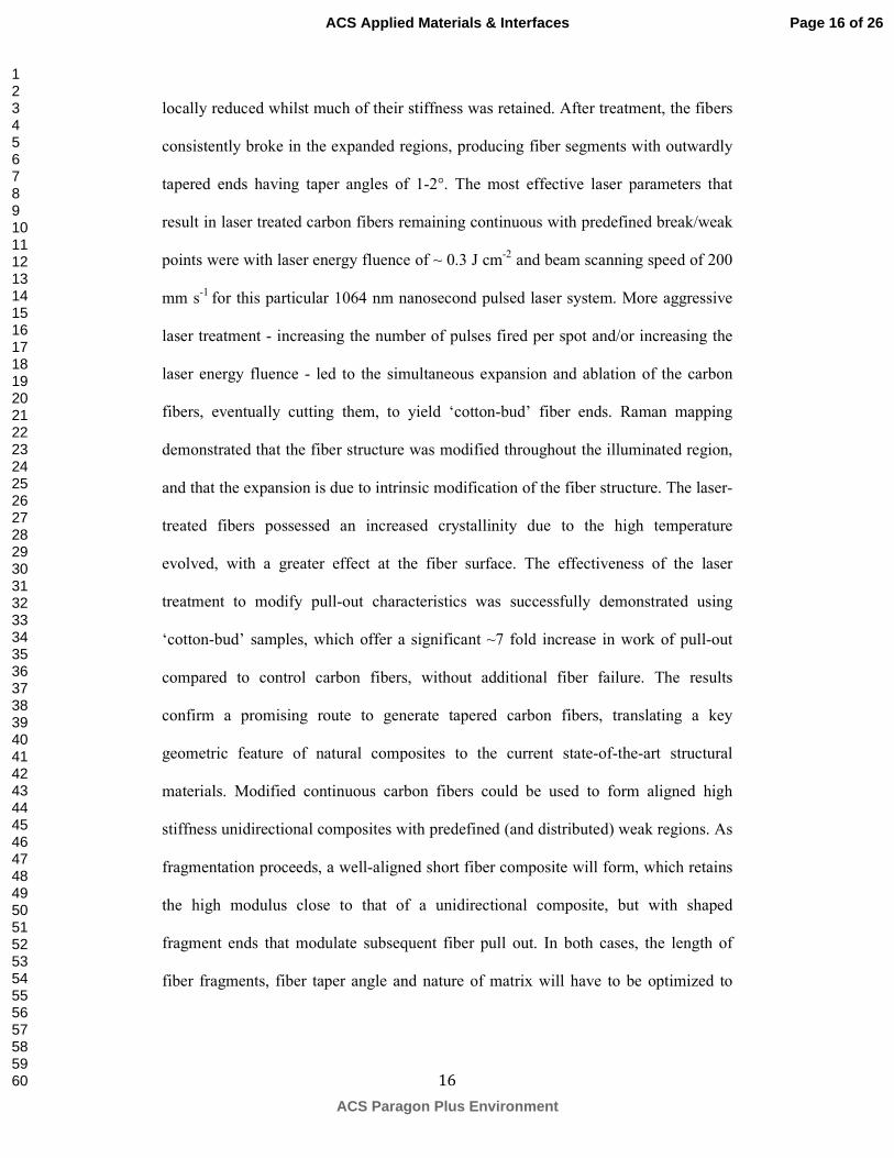
locally reduced whilst much of their stiffness was retained. After treatment, the fibers
consistently broke in the expanded regions, producing fiber segments with outwardly
tapered ends having taper angles of 1-2°. The most effective laser parameters that
result in laser treated carbon fibers remaining continuous with predefined break/weak
points were with laser energy fluence of ~ 0.3 J cm-2
and beam scanning speed of 200
mm s-1
for this particular 1064 nm nanosecond pulsed laser system. More aggressive
laser treatment - increasing the number of pulses fired per spot and/or increasing the
laser energy fluence - led to the simultaneous expansion and ablation of the carbon
fibers, eventually cutting them, to yield ‘cotton-bud’ fiber ends. Raman mapping
demonstrated that the fiber structure was modified throughout the illuminated region,
and that the expansion is due to intrinsic modification of the fiber structure. The laser-
treated fibers possessed an increased crystallinity due to the high temperature
evolved, with a greater effect at the fiber surface. The effectiveness of the laser
treatment to modify pull-out characteristics was successfully demonstrated using
‘cotton-bud’ samples, which offer a significant ~7 fold increase in work of pull-out
compared to control carbon fibers, without additional fiber failure. The results
confirm a promising route to generate tapered carbon fibers, translating a key
geometric feature of natural composites to the current state-of-the-art structural
materials. Modified continuous carbon fibers could be used to form aligned high
stiffness unidirectional composites with predefined (and distributed) weak regions. As
fragmentation proceeds, a well-aligned short fiber composite will form, which retains
the high modulus close to that of a unidirectional composite, but with shaped
fragment ends that modulate subsequent fiber pull out. In both cases, the length of
fiber fragments, fiber taper angle and nature of matrix will have to be optimized to
Page 16 of 26
ACS Paragon Plus Environment
ACS Applied Materials & Interfaces
123456789101112131415161718192021222324252627282930313233343536373839404142434445464748495051525354555657585960

17
maximise both sliding and load transfer. Theory developed for other model systems27-
30 will offer helpful guidelines.
References
(1) Fratzl, P.; Weinkamer, R. Nature’s Hierarchical Materials. Prog. Polym. Sci.
2007, 52, 1263-1334.
(2) Barthelat, F.; Tang, H.; Zavattieri, P.D.; Li, C-D.; Espinosa, H.D. On the
Mechanics of Mother-of-pearl: A Key Feature in the Material Hierarchical
Structure. J. Mech. Phys. Solids 2007, 55, 306-337.
(3) Rabiei, R.; Bekah, S.; Barthelat, F. Nacre from Mollusk Shells: Inspiration for
High-performance Nanocomposites, Chapter 5, pp. 113-149, in RSC Green
Chemistry No. 17 Natural Polymers, volume 2: Nanocomposites, Eds. John,
M.J. and Thomas S., Pub. The Royal Society of Chemistry.
(4) Barthelat, F.; Zhu, D. A Novel Biomimetic Material Duplicating the Structure
and Mechanics of Natural Nacre. J. Mater. Res. 2011, 26, 1203-1215.
(5) Humburg, H.; Zhu, D.; Bezina, S.; Barthelat, F. Bio-inspired Tapered Fibres for
Composites with Superior Toughness. Compos. Sci. Technol. 2012, 72, 1012-
1019.
(6) Beyerlein, I.J.; Zhu, Y.T.; Mahesh, S. On the Influence of Fiber Shape in Bone-
Shaped Short-fibre Composites. Compos. Sci. Technol. 2001, 61, 1341-1357.
(7) Lin, Z.; Li, V.C. Crack Bridging in Fibre Reinforced Cementitious Composites
with Slip-hardening Interfaces. J. Mech. Phys. Solids 1997, 45, 763-787.
(8) Zhu, Y.T.; Valdez, J.A.; Shi, N.; Lovatom, M.L.; Stout, M.G.; Zhou, S.J.; Butt,
D.P.; Blumenthal, W.R.; Lowe, T.C. A Composite Reinforced with Bone-
Shaped Short-fibres. Scr. Mater. 1998, 38, 1321-1325.
Page 17 of 26
ACS Paragon Plus Environment
ACS Applied Materials & Interfaces
123456789101112131415161718192021222324252627282930313233343536373839404142434445464748495051525354555657585960
18
(9) Wetherhold, R.C.; Lee, F.K. Shaped Ductile Fibres to Improve the Toughness
of Epoxy-matrix Composites. Compos. Sci. Technol. 2001, 61, 517-530.
(10) Bagwell, R.M.; McManaman, J.F.; Wetherhold, R.C. Short Shaped Copper
Fibres in Epoxy Matrix: Their Role in a Multifunctional Composite. Compos.
Sci. Technol. 2006, 66, 522-530.
(11) Bagwell, R.M.; Wetherhold, R.C. Fibre Pull-out Behaviour and Impact
Toughness of Short Shaped Copper Fibres in Thermoset Matrices. Composites,
Part A 2005, 36, 683-690.
(12) Bagwell, R.M.; Wetherhold, R.C. End-shaped Copper Fibers in an Epoxy
Matrix – Predicted Versus Actual Fibre Toughening. Theor. Appl. Fract. Mech.
2005, 43, 181-188.
(13) Tao, X.; Liu, J.; Koley, G.; Li, X. B/SiOx Nanonecklace Reinforced
Nanocomposites by Unique Mechanical Interlocking Mechanism. Adv. Mater.
2008, 20, 1-6.
(14) Diao, H.; Robinson, P.; Wisnom, M.R.; Bismarck, A. Unidirectional Carbon
Fibre Reinforced Polyamide-12 Composites with Enhanced Strain to Tensile
Failure by Introducing Fibre Waviness. Composites, Part A 2016, 87, 186-193.
(15) Cheng, C.F.; Tsui, Y.C.; Clyne, T.W. Application of a Three-dimensional Heat
Flow Model to Treat Laser Drilling of Carbon Fibre Composites. Acta Mater.
1998, 46, 4273-4285.
(16) Voisey, K.T.; Fouquet, S.; Roy, D.; Clyne, T.W. Fibre Swelling During Laser
Drilling of Carbon Fibre Composites. Opt. Lasers Eng. 2006, 44, 1185-1197.
(17) Romoli, L.; Fischer, F.; Kling, R. A Study on UV Laser Drilling of PEEK
Reinforced with Carbon Fibres. Opt. Lasers Eng. 2012, 50, 449-457.
Page 18 of 26
ACS Paragon Plus Environment
ACS Applied Materials & Interfaces
123456789101112131415161718192021222324252627282930313233343536373839404142434445464748495051525354555657585960

19
(18) Riveiro, A.; Quintero, F.; Lusquiños, F.; del Val, J.; Comesaña, R.; Boutinguiza,
M.; Pou, J. Experimental Study on the CO2 Laser Cutting of Carbon Fibre
Reinforced Plastic Composite. Composites, Part A 2012, 43, 1400-1409.
(19) Finger, J.; Weinand, M; Wortmann, D. Ablation and Cutting of Carbon-fibre
Reinforced Plastics using Picosecond Pulsed Laser Radiation with High
Average Power. J. Laser Appl. 2013, 25, 042007.
(20) O’Driscoll, D.; Hardwick, J.; Young, T.; Ryan, J. Lightning Strike of Perforated
Carbon Fibre Epoxy Laminar Flow Panels. J. Compos. Technol. Res. 2000, 22,
71-76.
(21) Salama, A; Li, L; Mativenga, P; Sabli, A. High-power Picosecond Laser
Drilling/machining of Carbon Fibre-reinforced Polymer (CFRP) Composites.
Appl. Phys. A: Mater. Sci. Process. 2016, 122, 1-11.
(22) Ford, R.A. Thermo-ductile Composites: New Materials for 21st Century
Manufacturing - Micro-perforation Symmetry. Mater. Des. 2002, 23, 431-439.
(23) Matthams, T.J.; Clyne, T.W. Mechanical Properties of Long-fibre
Thermoplastic Composites with Laser Drilled Microperforations 1. Effect of
Perforations in Consolidated Material. Compos. Sci. Technol. 1999, 59, 1169-
1180.
(24) Matthams, T.J.; Clyne, T.W. Mechanical Properties of Long-fibre
Thermoplastic Composites with Laser Drilled Perforations 2. Effect of Prior
Plastic Strain. Compos. Sci. Technol. 1999, 59, 1181-1187.
(25) Dresselhaus, M.S.; Dresselhaus, G.; Saito, R.; Jorio, A. Raman Spectroscopy of
Carbon Nanotubes. Phys. Rep. 2005, 409, 47-99.
Page 19 of 26
ACS Paragon Plus Environment
ACS Applied Materials & Interfaces
123456789101112131415161718192021222324252627282930313233343536373839404142434445464748495051525354555657585960

20
(26) Hampe, A.; Kalinka, G.; Meretz, S.; Schulz, E. An Advanced Equipment for
Single-fibre Pull-out Test Designed to Monitor the Fracture Process.
Composites 1995, 26, 40-46.
(27) Jackson, A.P.; Vincent, J.F.V.; Turner, R.M. The Mechanical Design of Nacre.
Proc. R. Soc. B 1988, 234, 415-440.
(28) Gao, H.; Ji, B.; Jager, I.L.; Arzt, E.; Fratzl, P. Materials Become Insensitive to
Flaws at Nanoscale: Lessons from Nature. Proc. Natl. Acad. Sci. U. S. A. 2003,
100, 5597-5600.
(29) Checa, A.G.; Cartwright, J.H.E.; Willinger, M-G. Mineral Bridges in Nacre. J.
Struct. Biol. 2011, 176, 330-339.
(30) Shao, Y.; Zhao, H-P.; Feng, X-I. Optimal Characteristic Nanosizes of Mineral
Bridges in Mollusc Nacre. RSC Adv. 2014, 4, 32451-32456.
Acknowledgements
Stephen A. Hodge is greatly acknowledged for his help obtaining Raman spectra and
mapping. The authors kindly acknowledge the funding for this research provided by
EPSRC programme Grant EP/I02946X/1 on High Performance Ductile Composite
Technology (HiPerDuCT), in collaboration with the University of Bristol. Amin
Abdolvand is an EPSRC Career Acceleration Fellow at the University of Dundee
(EP/I004173/1).
Page 20 of 26
ACS Paragon Plus Environment
ACS Applied Materials & Interfaces
123456789101112131415161718192021222324252627282930313233343536373839404142434445464748495051525354555657585960

21
Figure Captions
Figure 1. Schematic depicting (A) laser induced shape modification of carbon fibers
(CF) mounted in card grids/frames from which (B) single frames containing fibers
were cut, (C) Single fiber tensile tests were carried out after morphology
characterization. SEM example of an expanded region after laser treatment, laser path
highlighted red, altered morphology shown within the dashed red box. Designated
fiber types detailed in box, SEM of irradiated carbon fiber samples illustrating the
different observed morphologies before/after treatment, dependent on the
experimental variables, average power, repetition rate and beam scanning speeds.
Schematic shown adjacent shows average dimensions for Control, Expanded,
Expanded/Ablated and Cotton-bud end fibers. Top right, distribution plot of
maximum Expanded fiber diameters as a function of affected length deviating from
as-received diameter (Control).
Figure 2. Tensile mechanical properties of (a) force to failure, (b) strength, (c) strain,
and (d) modulus for Expanded and Expanded/Ablated fibers, relative to Control
carbon fibers, as function of fiber expansion. Both force to failure and strength
(normalised to control fiber diameter) are presented as the diameter at break of the
failed laser treated fibers could not be ascertained.
Figure 3. Representative SEM image of an expanded fibers post tensile failure,
demonstrating that the fibers failed near the thickest region.
Figure 4. Raman spectroscopy of fibers (Control, Expanded and Expanded/Ablated
carbon fibers) along the fiber axis and at the fracture surfaces. (a) Schematic
illustrating the relative position of (b) Raman spectra, Regions 1 to 5 on fiber surface,
Page 21 of 26
ACS Paragon Plus Environment
ACS Applied Materials & Interfaces
123456789101112131415161718192021222324252627282930313233343536373839404142434445464748495051525354555657585960

22
with spectra separated by at least 20 µm, (c) Schematic cartoon Raman line-of-sight
for fracture surfaces of (d) SEM, optical with schematic inset to describe the relative
positions of (e) Regions A to E for the respective Raman graphs at the fracture
surface. (f) Raman mapping of the fracture surfaces with relative intensity of G mode,
and corresponding ID/IG and I2D/IG ratio shown as Raman maps within the range of 0.5
and 1.5 (colour image found on-line). N.B. Expanded and Expanded/Ablated fibers
were irradiated in the B-C-D face in the relative fracture surfaces.
Figure 5. Optical micrograph series comparing the pull-out behaviour of (a) Control
carbon fiber compared with (b) Cotton-bud end carbon fiber. Note that the field of
view was adjusted during the series to follow the fiber end, all images have been
positioned such that embedded position is maintained (blue dotted line), fiber ends are
highlighted with an arrow where appropriate. Representative load-displacement plots
of the pull-out behaviour of (c) Control carbon fiber and Cotton-bud end carbon fiber,
with inset of average values of the interfacial shear strength (τIFSS) and work of pull-
out.
Page 22 of 26
ACS Paragon Plus Environment
ACS Applied Materials & Interfaces
123456789101112131415161718192021222324252627282930313233343536373839404142434445464748495051525354555657585960
23
FIGURES:
FIGURES:
Figure 1.
Page 23 of 26
ACS Paragon Plus Environment
ACS Applied Materials & Interfaces
123456789101112131415161718192021222324252627282930313233343536373839404142434445464748495051525354555657585960
24
0 10 20 30 40 50
160
180
200
220
240
260
217 ± 12
206 ± 6
217 ± 11213 ± 18
193 ± 28
CONTROL CF EXPANDED CF EXPANDED/ABLATED CF
Modulus [GPa]
Fiber expansion, max dia. rel. to control fiber dia. [%]
254 ± 2
0 10 20 30 40 50
0.0
0.5
1.0
1.5
2.0
0.61 ± 0.05
0.73 ± 0.14
1.33 ± 0.61
0.51 ± 0.12
1.09 ± 0.17
1.77 ± 0.04
CONTROL CF EXPANDED CF EXPANDED/ABLATED CF
Strain [%]
Fiber expansion, max dia. rel. to control fiber dia. [%]
0 10 20 30 40 50
0
1000
2000
3000
4000
5000
1406 ± 153
1551 ± 308
2472 ± 480
1167 ± 382
2296 ± 665
4602 ± 123
Strength [MPa]
Fiber expansion, max dia. rel. to control fiber dia. [%]
CONTROL CF EXPANDED CF EXPANDED/ABLATED CF
0 10 20 30 40 50
0
50
100
150
200
52 ± 657 ± 13
93 ± 16
45 ± 16
92 ± 29
175 ± 5
CONTROL CF EXPANDED CF EXPANDED/ABLATED CF
Tensile force to failure [mN]
Fiber expansion, max dia. rel. to control fiber dia. [%]
(a)
(d)
(b)
(c)
Page 24 of 26
ACS Paragon Plus Environment
ACS Applied Materials & Interfaces
123456789101112131415161718192021222324252627282930313233343536373839404142434445464748495051525354555657585960

25
Figure 2.
Figure 3.
Figure 4.
Page 25 of 26
ACS Paragon Plus Environment
ACS Applied Materials & Interfaces
123456789101112131415161718192021222324252627282930313233343536373839404142434445464748495051525354555657585960

26
Figure 5.
TABLE OF CONTENTS GRAPHIC
Page 26 of 26
ACS Paragon Plus Environment
ACS Applied Materials & Interfaces
123456789101112131415161718192021222324252627282930313233343536373839404142434445464748495051525354555657585960