Embed Size (px)
Citation preview
B.1
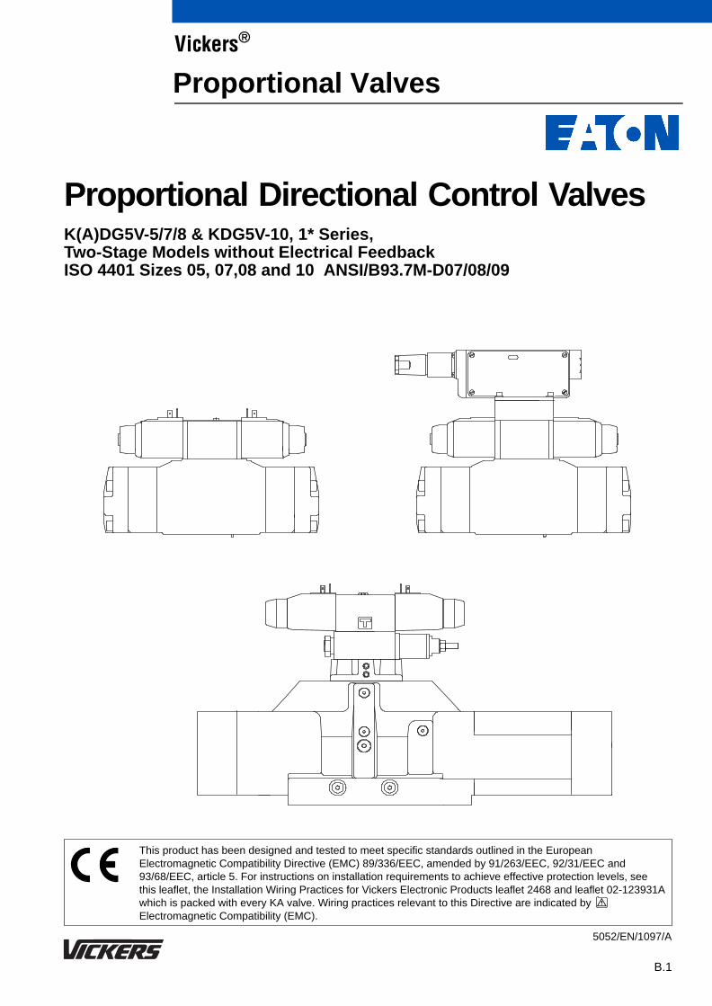
Proportional Directional Control Valves K(A)DG5V-5/7/8 & KDG5V-10, 1* Series, Two-Stage Models without Electrical Feedback ISO 4401 Sizes 05, 07,08 and 10 ANSI/B93.7M-D07/08/09
This product has been designed and tested to meet specific standards outlined in the EuropeanElectromagnetic Compatibility Directive (EMC) 89/336/EEC, amended by 91/263/EEC, 92/31/EEC and93/68/EEC, article 5. For instructions on installation requirements to achieve effective protection levels, seethis leaflet, the Installation Wiring Practices for Vickers Electronic Products leaflet 2468 and leaflet 02-123931Awhich is packed with every KA valve. Wiring practices relevant to this Directive are indicated byElectromagnetic Compatibility (EMC).
5052/EN/1097/A
Vickers®
Proportional Valves
B.2
Introduction
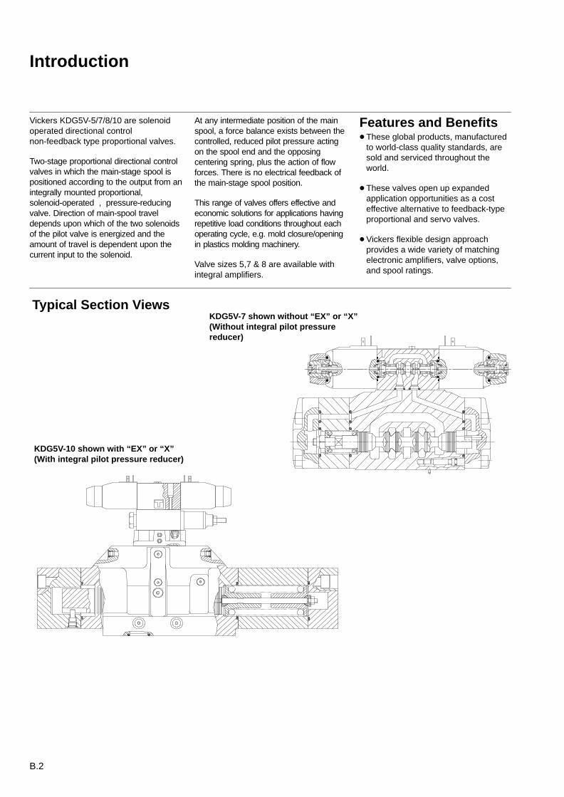
Vickers KDG5V-5/7/8/10 are solenoidoperated directional controlnon-feedback type proportional valves.
Two-stage proportional directional controlvalves in which the main-stage spool ispositioned according to the output from anintegrally mounted proportional,solenoid-operated , pressure-reducingvalve. Direction of main-spool traveldepends upon which of the two solenoidsof the pilot valve is energized and theamount of travel is dependent upon thecurrent input to the solenoid.
At any intermediate position of the mainspool, a force balance exists between thecontrolled, reduced pilot pressure actingon the spool end and the opposingcentering spring, plus the action of flowforces. There is no electrical feedback ofthe main-stage spool position.
This range of valves offers effective andeconomic solutions for applications havingrepetitive load conditions throughout eachoperating cycle, e.g. mold closure/openingin plastics molding machinery.
Valve sizes 5,7 & 8 are available withintegral amplifiers.
Features and Benefits These global products, manufactured
to world-class quality standards, aresold and serviced throughout theworld.
These valves open up expandedapplication opportunities as a costeffective alternative to feedback-typeproportional and servo valves.
Vickers flexible design approachprovides a wide variety of matchingelectronic amplifiers, valve options,and spool ratings.
Typical Section Views
KDG5V-10 shown with “EX” or “X”(With integral pilot pressure reducer)
KDG5V-7 shown without “EX” or “X”(Without integral pilot pressurereducer)
B.3
Table of Contents
Introduction B.2. . . . . . . . . . . . . . . . . . . . . . . . . . . . . . . . . . . . . . . . . . . . . . . . . . . . . . . . . . . . . . . . . . . . . . . . . . . . . . . . . . . . . . . . . . . . . . . . . .
Features and benefits B.2. . . . . . . . . . . . . . . . . . . . . . . . . . . . . . . . . . . . . . . . . . . . . . . . . . . . . . . . . . . . . . . . . . . . . . . . . . . . . . . . . . . . . . . . .
Typical section B.2. . . . . . . . . . . . . . . . . . . . . . . . . . . . . . . . . . . . . . . . . . . . . . . . . . . . . . . . . . . . . . . . . . . . . . . . . . . . . . . . . . . . . . . . . . . . . . .
Functional Symbols B.4. . . . . . . . . . . . . . . . . . . . . . . . . . . . . . . . . . . . . . . . . . . . . . . . . . . . . . . . . . . . . . . . . . . . . . . . . . . . . . . . . . . . . . . . . . .
Model Codes B.5. . . . . . . . . . . . . . . . . . . . . . . . . . . . . . . . . . . . . . . . . . . . . . . . . . . . . . . . . . . . . . . . . . . . . . . . . . . . . . . . . . . . . . . . . . . . . . . .
Spool Data B.6. . . . . . . . . . . . . . . . . . . . . . . . . . . . . . . . . . . . . . . . . . . . . . . . . . . . . . . . . . . . . . . . . . . . . . . . . . . . . . . . . . . . . . . . . . . . . . . . . .
Operating Data B.7. . . . . . . . . . . . . . . . . . . . . . . . . . . . . . . . . . . . . . . . . . . . . . . . . . . . . . . . . . . . . . . . . . . . . . . . . . . . . . . . . . . . . . . . . . . . . . .
Performance Characteristics B.9. . . . . . . . . . . . . . . . . . . . . . . . . . . . . . . . . . . . . . . . . . . . . . . . . . . . . . . . . . . . . . . . . . . . . . . . . . . . . . . . . . .
Installation Dimensions B.12. . . . . . . . . . . . . . . . . . . . . . . . . . . . . . . . . . . . . . . . . . . . . . . . . . . . . . . . . . . . . . . . . . . . . . . . . . . . . . . . . . . . . . .
Subplates, Connection Plates and Mounting Surfaces B.17. . . . . . . . . . . . . . . . . . . . . . . . . . . . . . . . . . . . . . . . . . . . . . . . . . . . . . . . . . . .
Electrical Information B.31. . . . . . . . . . . . . . . . . . . . . . . . . . . . . . . . . . . . . . . . . . . . . . . . . . . . . . . . . . . . . . . . . . . . . . . . . . . . . . . . . . . . . . . .
Installation Data B.38. . . . . . . . . . . . . . . . . . . . . . . . . . . . . . . . . . . . . . . . . . . . . . . . . . . . . . . . . . . . . . . . . . . . . . . . . . . . . . . . . . . . . . . . . . . . .
Application Data B.39. . . . . . . . . . . . . . . . . . . . . . . . . . . . . . . . . . . . . . . . . . . . . . . . . . . . . . . . . . . . . . . . . . . . . . . . . . . . . . . . . . . . . . . . . . . . .
B.4
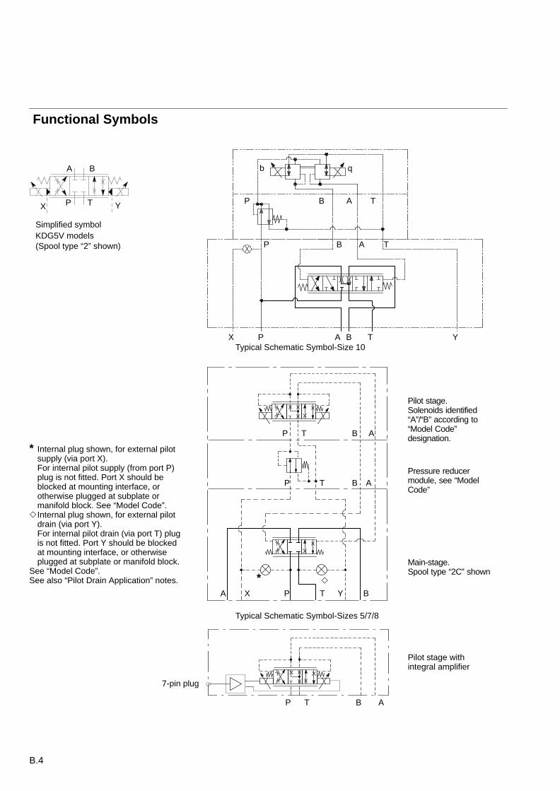
Functional Symbols
A B
P T
Pilot stage.Solenoids identified“A”/“B” according to“Model Code”designation.
Pressure reducermodule, see “ModelCode”
Main-stage.Spool type “2C” shown
X Y
* Internal plug shown, for external pilot supply (via port X).For internal pilot supply (from port P) plug is not fitted. Port X should be blocked at mounting interface, or otherwise plugged at subplate or manifold block. See “Model Code”.
Internal plug shown, for external pilotdrain (via port Y).For internal pilot drain (via port T) plugis not fitted. Port Y should be blockedat mounting interface, or otherwise plugged at subplate or manifold block.
See “Model Code”. See also “Pilot Drain Application” notes.
P T B A
T B AP
T BA P YX
*
P B A T
P B A T
X YP A B T
b q
Simplified symbolKDG5V models(Spool type “2” shown)
Typical Schematic Symbol-Size 10
Typical Schematic Symbol-Sizes 5/7/8
7-pin plug
Pilot stage with integral amplifier
P T B A
B.5
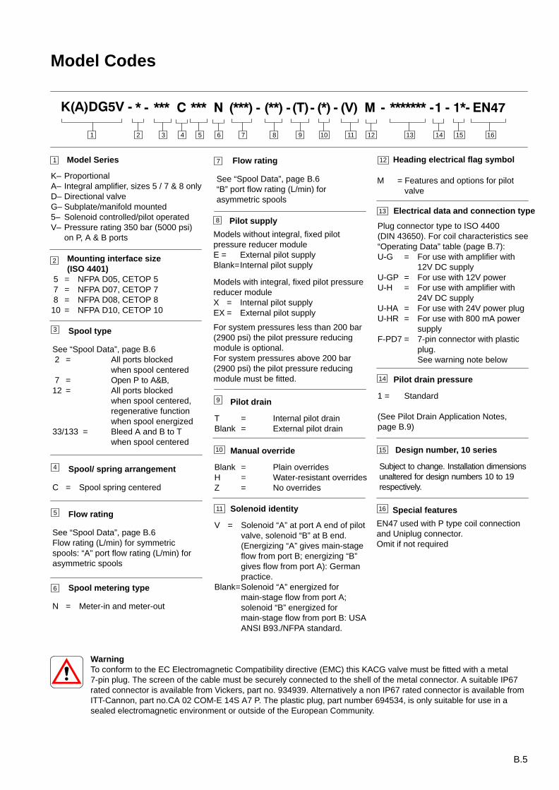
Model Codes
Manual override
Blank = Plain overridesH = Water-resistant overridesZ = No overrides
Spool/ spring arrangement
C = Spool spring centered
Solenoid identity
V = Solenoid “A” at port A end of pilot valve, solenoid “B” at B end. (Energizing “A” gives main-stage flow from port B; energizing “B” gives flow from port A): German practice.
Blank=Solenoid “A” energized for main-stage flow from port A; solenoid “B” energized for main-stage flow from port B: USA ANSI B93./NFPA standard.
Flow rating
See “Spool Data”, page B.6“B” port flow rating (L/min) forasymmetric spools
Spool metering type
N = Meter-in and meter-out
Flow rating
See “Spool Data”, page B.6Flow rating (L/min) for symmetricspools: “A” port flow rating (L/min) forasymmetric spools
5
Electrical data and connection type
Plug connector type to ISO 4400 (DIN 43650). For coil characteristics see“Operating Data” table (page B.7):U-G = For use with amplifier with
12V DC supplyU-GP = For use with 12V powerU-H = For use with amplifier with
24V DC supplyU-HA = For use with 24V power plugU-HR = For use with 800 mA power
supplyF-PD7 = 7-pin connector with plastic
plug. See warning note below
9 Pilot drain
T = Internal pilot drainBlank = External pilot drain
Pilot supply
Models without integral, fixed pilotpressure reducer moduleE = External pilot supplyBlank=Internal pilot supply
Models with integral, fixed pilot pressurereducer moduleX = Internal pilot supplyEX = External pilot supply
4
Spool type
See “Spool Data”, page B.6 2 = All ports blocked
when spool centered 7 = Open P to A&B, 12 = All ports blocked
when spool centered, regenerative function when spool energized
33/133 = Bleed A and B to T when spool centered
Pilot drain pressure
1 = Standard
(See Pilot Drain Application Notes,page B.9)
Mounting interface size(ISO 4401)
5 = NFPA D05, CETOP 5 7 = NFPA D07, CETOP 7 8 = NFPA D08, CETOP 810 = NFPA D10, CETOP 10
For system pressures less than 200 bar(2900 psi) the pilot pressure reducingmodule is optional.For system pressures above 200 bar(2900 psi) the pilot pressure reducingmodule must be fitted.
Design number, 10 series
Subject to change. Installation dimensionsunaltered for design numbers 10 to 19respectively.
Special features
EN47 used with P type coil connectionand Uniplug connector.Omit if not required
Model Series
K– ProportionalA– Integral amplifier, sizes 5 / 7 & 8 onlyD– Directional valveG– Subplate/manifold mounted5– Solenoid controlled/pilot operatedV– Pressure rating 350 bar (5000 psi)
on P, A & B ports
1
2
3
8
10
13
14
15
16
7
6
11
3 4 5 876 9 101 2 11 12 13 14 15 16
Heading electrical flag symbol
M = Features and options for pilot valve
12
WarningTo conform to the EC Electromagnetic Compatibility directive (EMC) this KACG valve must be fitted with a metal7-pin plug. The screen of the cable must be securely connected to the shell of the metal connector. A suitable IP67rated connector is available from Vickers, part no. 934939. Alternatively a non IP67 rated connector is available fromITT-Cannon, part no.CA 02 COM-E 14S A7 P. The plastic plug, part number 694534, is only suitable for use in asealed electromagnetic environment or outside of the European Community.
B.6
Spool Data
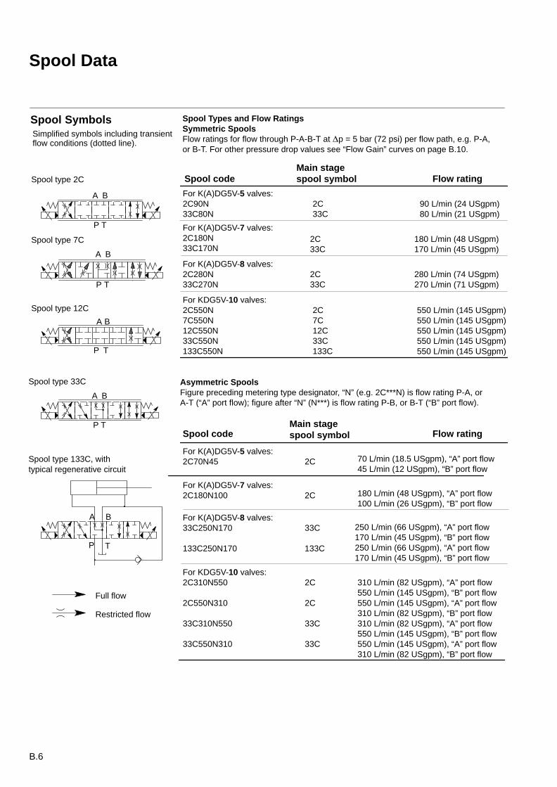
For K(A)DG5V-8 valves:33C250N170
133C250N170
For K(A)DG5V-7 valves:2C180N33C170N
2C33C
For K(A)DG5V-8 valves:2C280N33C270N
Asymmetric SpoolsFigure preceding metering type designator, “N” (e.g. 2C***N) is flow rating P-A, orA-T (“A” port flow); figure after “N” (N***) is flow rating P-B, or B-T (“B” port flow).
For KDG5V-10 valves:2C310N550
2C550N310
33C310N550
33C550N310
2C7C12C33C133C
2C33C
310 L/min (82 USgpm), “A” port flow550 L/min (145 USgpm), “B” port flow550 L/min (145 USgpm), “A” port flow310 L/min (82 USgpm), “B” port flow310 L/min (82 USgpm), “A” port flow550 L/min (145 USgpm), “B” port flow550 L/min (145 USgpm), “A” port flow310 L/min (82 USgpm), “B” port flow
Full flow
Restricted flow
Spool SymbolsSimplified symbols including transientflow conditions (dotted line).
Spool Types and Flow RatingsSymmetric SpoolsFlow ratings for flow through P-A-B-T at p = 5 bar (72 psi) per flow path, e.g. P-A,or B-T. For other pressure drop values see “Flow Gain” curves on page B.10.
90 L/min (24 USgpm)80 L/min (21 USgpm)
180 L/min (48 USgpm)170 L/min (45 USgpm)
280 L/min (74 USgpm)270 L/min (71 USgpm)
550 L/min (145 USgpm)550 L/min (145 USgpm)550 L/min (145 USgpm)550 L/min (145 USgpm)550 L/min (145 USgpm)
2C33C
For KDG5V-10 valves:2C550N7C550N12C550N33C550N133C550N
For K(A)DG5V-5 valves:2C90N33C80N
Spool codeMain stagespool symbol Flow rating
70 L/min (18.5 USgpm), “A” port flow45 L/min (12 USgpm), “B” port flow
180 L/min (48 USgpm), “A” port flow100 L/min (26 USgpm), “B” port flow
250 L/min (66 USgpm), “A” port flow170 L/min (45 USgpm), “B” port flow250 L/min (66 USgpm), “A” port flow170 L/min (45 USgpm), “B” port flow
2C
2C
33C
133C
For K(A)DG5V-7 valves:2C180N100
For K(A)DG5V-5 valves:2C70N45
2C
2C
33C
33C
Spool codeMain stagespool symbol Flow rating
Spool type 33C
A B
P T
A B
P T
Spool type 133C, withtypical regenerative circuit
A B
P T
A B
P T
A B
P T
Spool type 7C
Spool type 12C
Spool type 2C

B.7
Operating Data
Data is typical:With fluid at 36 cSt (168 SUS) and 50C (122F). Using recommended Vickers amplifier to drive KDG5V models.
KDG5V valves
Installation and Start-up Guidelines ML-B-9046
Max. solenoid currentCoil type:
U-GU-GPU-HU-HAU-HR
3.5A3.0A1.6A0.94A0.8A
Coil resistanceCoil type:U-GU-GPU-HU-HAU-HR
At 20C (68F) Max. operating
1.65Ω 2.66Ω2.0Ω 3.1Ω 7.3 Ω 11.3 Ω22.1Ω 34.6Ω19.1Ω 29.9Ω
Coil inductance measured at 1000 Hz and 150 mVCoil type:
U-GU-GPU-HU-HAU-HR
4 mH6 mH19 mH55 mH51 mH
HysteresisSize 5/7/8Size 10
4% of rated max. flow Size 5/7/8<6% of rated max. flow Size 10
Repeatability:Size 5/7/8Size 10
<3%8%
Relative duty factor Continuous rating (ED = 100%)
Type of electrical protection, with electrical plugs fitted correctly IEC 144 Class IP65Electrical connection ISO 4400 (DIN 43650)
Recommended drive amplifier Vickers Eurocard type:EEA-PAM-520-A-14 (one ramp), or EEA-PAM-523-A-32(two ramps)
B.8
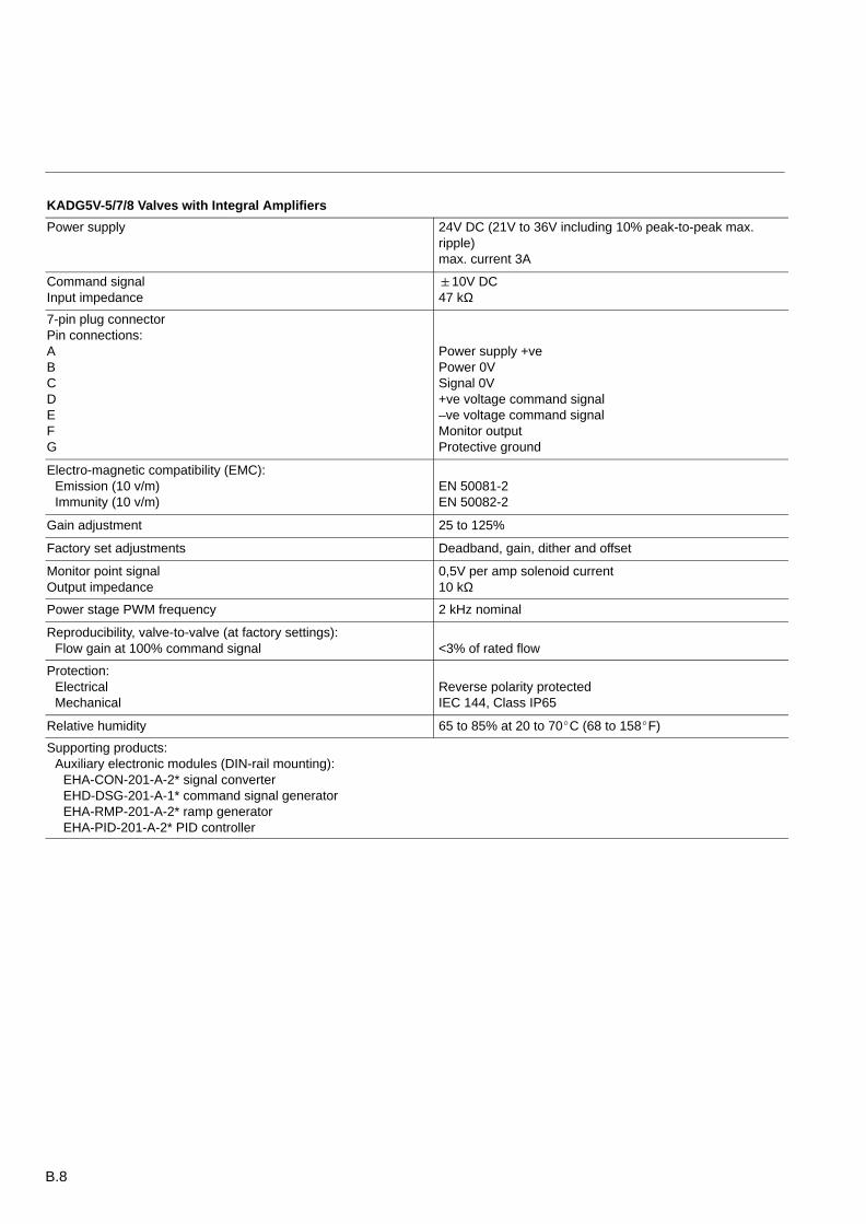
KADG5V-5/7/8 Valves with Integral Amplifiers
Power supply 24V DC (21V to 36V including 10% peak-to-peak max.ripple)max. current 3A
Command signalInput impedance
10V DC47 kΩ
7-pin plug connectorPin connections:ABCDEFG
Power supply +vePower 0VSignal 0V+ve voltage command signal–ve voltage command signalMonitor outputProtective ground
Electro-magnetic compatibility (EMC):Emission (10 v/m)Immunity (10 v/m)
EN 50081-2EN 50082-2
Gain adjustment 25 to 125%
Factory set adjustments Deadband, gain, dither and offset
Monitor point signalOutput impedance
0,5V per amp solenoid current10 kΩ
Power stage PWM frequency 2 kHz nominal
Reproducibility, valve-to-valve (at factory settings):Flow gain at 100% command signal <3% of rated flow
Protection:ElectricalMechanical
Reverse polarity protectedIEC 144, Class IP65
Relative humidity 65 to 85% at 20 to 70C (68 to 158F)
Supporting products:Auxiliary electronic modules (DIN-rail mounting):
EHA-CON-201-A-2* signal converterEHD-DSG-201-A-1* command signal generatorEHA-RMP-201-A-2* ramp generatorEHA-PID-201-A-2* PID controller
B.9
Performance Characteristics
EX
X
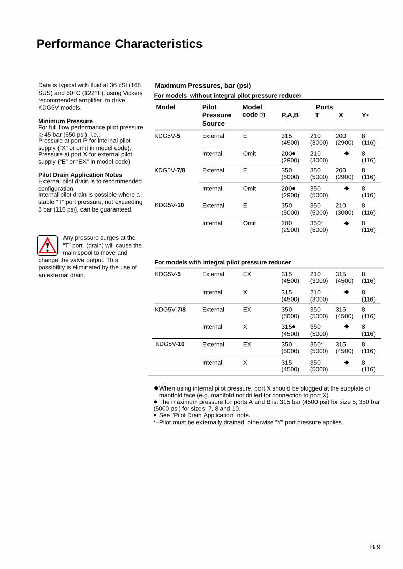
Data is typical with fluid at 36 cSt (168SUS) and 50C (122F), using Vickersrecommended amplifier to driveKDG5V models.
Minimum PressureFor full flow performance pilot pressure45 bar (650 psi), i.e.:Pressure at port P for internal pilotsupply (“X” or omit in model code).Pressure at port X for external pilotsupply (“E” or “EX” in model code).
Pilot Drain Application NotesExternal pilot drain is to recommendedconfiguration.Internal pilot drain is possible where astable “T” port pressure, not exceeding 8 bar (116 psi), can be guaranteed.
For models with integral pilot pressure reducer
KDG5V-10
For models without integral pilot pressure reducer
KDG5V-7/8
KDG5V-5
KDG5V-7/8
KDG5V-5
Model PilotPressure Source
Any pressure surges at the “T” port (drain) will cause themain spool to move and
change the valve output. Thispossibility is eliminated by the use ofan external drain.
Modelcode
PortsP,A,B T X Y
External E 315(4500)
210(3000)
200(2900)
8(116)
Internal Omit 200(2900)
210(3000)
8(116)
External E 350(5000)
200(2900)
8(116)
Internal Omit 200(2900)
350(5000)
8(116)
350(5000)
External EX
Internal X
315(4500)
315(4500)
210(3000)
210(3000)
315(4500)
8(116)
8(116)
External EX
Internal X
350(5000)
350(5000)
315(4500)
8(116)
315(4500)
350(5000)
8(116)
External
Internal
350*(5000)
315(4500)
8(116)
350(5000)
315(4500)
350(5000)
8(116)
When using internal pilot pressure, port X should be plugged at the subplate or manifold face (e.g. manifold not drilled for connection to port X).
The maximum pressure for ports A and B is: 315 bar (4500 psi) for size 5; 350 bar (5000 psi) for sizes 7, 8 and 10. See “Pilot Drain Application” note.*–Pilot must be externally drained, otherwise “Y” port pressure applies.
Maximum Pressures, bar (psi)
7
KDG5V-10 External
Internal
E
Omit
350(5000)
350(5000)
210(3000)
8(116)
200(2900)
350*(5000)
8(116)
B.10
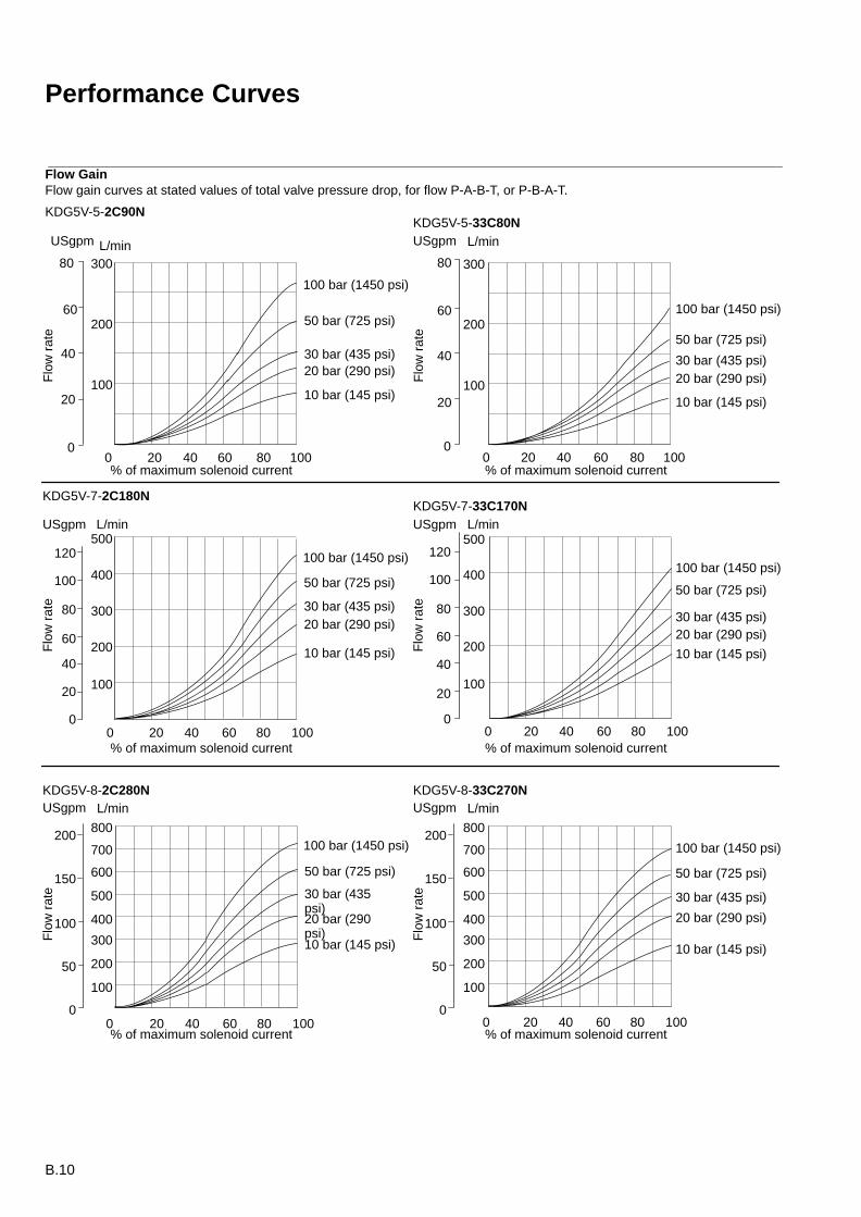
Performance Curves
Flow GainFlow gain curves at stated values of total valve pressure drop, for flow P-A-B-T, or P-B-A-T.
KDG5V-5-2C90N
300
200
100
20 40 60 80 100
80
60
40
20
00
L/min
100 bar (1450 psi)
50 bar (725 psi)
300
200
100
20 40 60 80 100
80
60
40
20
00
USgpm L/minUSgpm
30 bar (435 psi)20 bar (290 psi)
10 bar (145 psi)
100 bar (1450 psi)
50 bar (725 psi)
30 bar (435 psi)20 bar (290 psi)
10 bar (145 psi)
KDG5V-5-33C80N
300
200
100
20 40 60 80 100
80
60
40
20
00
L/min
400
500
100
120
300
200
100
20 40 60 80 100
80
60
40
20
00
USgpm L/min
400
500
100
120
USgpm
KDG5V-7-2C180NKDG5V-7-33C170N
100 bar (1450 psi)
50 bar (725 psi)
30 bar (435 psi)20 bar (290 psi)
10 bar (145 psi)
100 bar (1450 psi)
50 bar (725 psi)
30 bar (435 psi)20 bar (290 psi)
10 bar (145 psi)
300
200
100
20 40 60 80 100
50
00
L/min
400
500
100
150 600
700
800200
20 40 60 80 1000
USgpmKDG5V-8-2C280N KDG5V-8-33C270N
100 bar (1450 psi)
50 bar (725 psi)
30 bar (435psi)20 bar (290psi)10 bar (145 psi)
100 bar (1450 psi)
50 bar (725 psi)
30 bar (435 psi)
20 bar (290 psi)
10 bar (145 psi)
% of maximum solenoid current% of maximum solenoid current
% of maximum solenoid current% of maximum solenoid current
% of maximum solenoid current% of maximum solenoid current
Flo
w r
ate
300
200
100
50
0
L/min
400
500
100
150 600
700
800200
USgpm
Flo
w r
ate
Flo
w r
ate
Flo
w r
ate
Flo
w r
ate
Flo
w r
ate
B.11
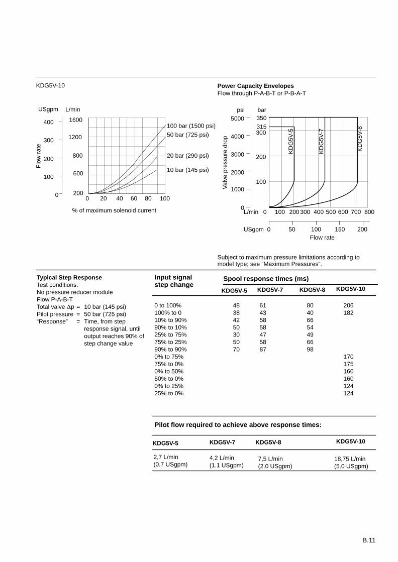
Typical Step ResponseTest conditions:No pressure reducer moduleFlow P-A-B-TTotal valve p = 10 bar (145 psi)Pilot pressure = 50 bar (725 psi)“Response” = Time, from step
response signal, until output reaches 90% ofstep change value
Input signalstep change
Spool response times (ms)
0 to 100%100% to 010% to 90%90% to 10%25% to 75%75% to 25%90% to 90%0% to 75%75% to 0%0% to 50%50% to 0%0% to 25%25% to 0%
48384250305070
61435858475887
80406654496698
206182
170175160160124124
KDG5V-5 KDG5V-7 KDG5V-8 KDG5V-10
Pilot flow required to achieve above response times:
KDG5V-5 KDG5V-7 KDG5V-8 KDG5V-10
2,7 L/min(0.7 USgpm)
4,2 L/min(1.1 USgpm)
7,5 L/min(2.0 USgpm)
600
20020 40 60 80 100
100
00
L/min
800200
300 1200
1600400
USgpm
100 bar (1500 psi)
50 bar (725 psi)
20 bar (290 psi)
10 bar (145 psi)
% of maximum solenoid current
Flo
w r
ate
KDG5V-10
barpsi350
315300
200
100
0 100 200 300 400 500 600 700 800L/min
0 50 100 150 200USgpm
0
2000
1000
3000
4000
5000
Val
ve p
ress
ure
drop
Flow rate
KD
G5V
-8
KD
G5V
-7
KD
G5V
-5
Power Capacity EnvelopesFlow through P-A-B-T or P-B-A-T
Subject to maximum pressure limitations according tomodel type; see “Maximum Pressures”.
18,75 L/min(5.0 USgpm)
B.12
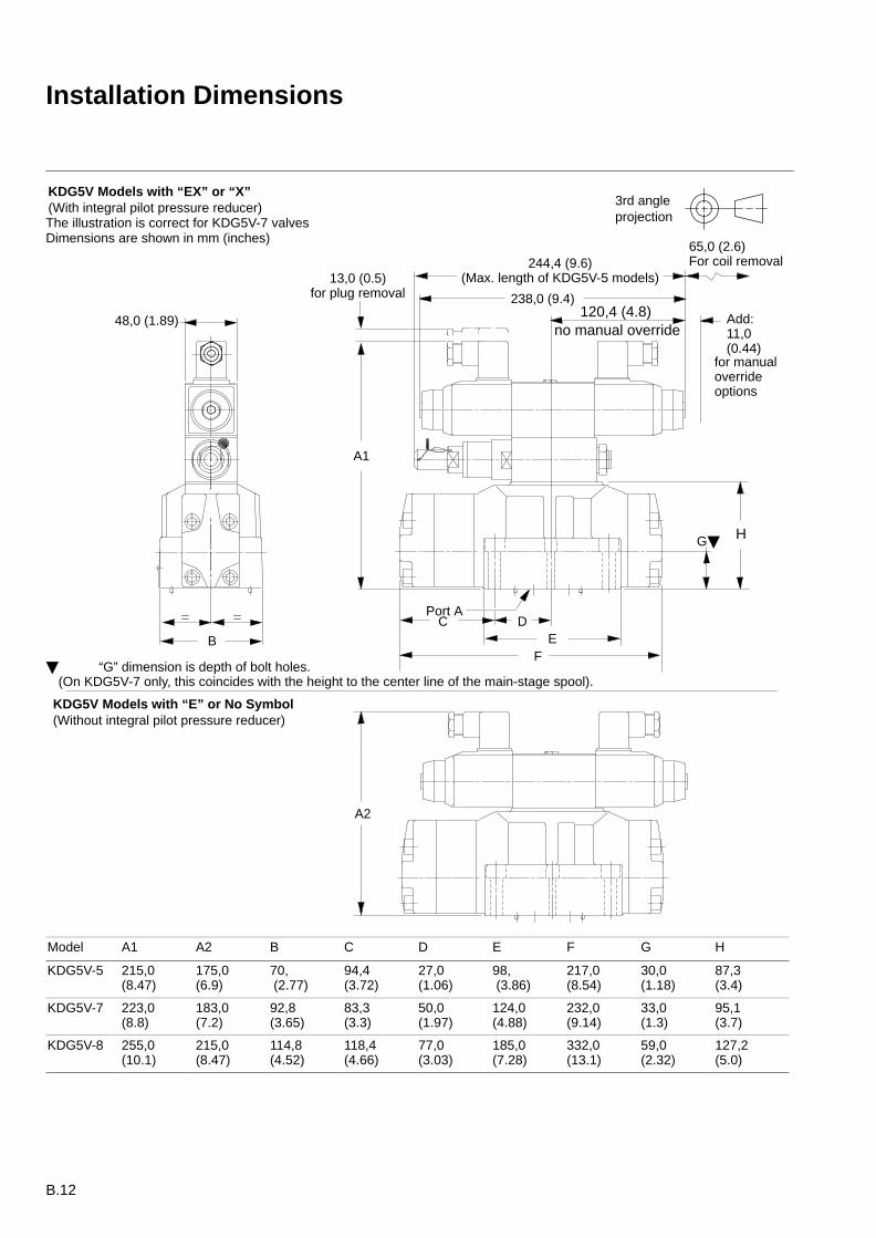
Installation Dimensions
KDG5V Models with “EX” or “X”(With integral pilot pressure reducer) 3rd angle
projection
C
A1
B
DE
F
GH
238,0 (9.4)
244,4 (9.6)(Max. length of KDG5V-5 models)13,0 (0.5)
for plug removal
65,0 (2.6)For coil removal
for manualoverrideoptions
Add:11,0(0.44)
Port A
48,0 (1.89)
“G” dimension is depth of bolt holes.(On KDG5V-7 only, this coincides with the height to the center line of the main-stage spool).
120,4 (4.8)no manual override
KDG5V Models with “E” or No Symbol(Without integral pilot pressure reducer)
A2
The illustration is correct for KDG5V-7 valvesDimensions are shown in mm (inches)
Model A1 A2 B C D E F G H
KDG5V-5 215,0(8.47)
175,0(6.9)
70, (2.77)
94,4(3.72)
27,0(1.06)
98, (3.86)
217,0(8.54)
30,0(1.18)
87,3(3.4)
KDG5V-7 223,0(8.8)
183,0(7.2)
92,8(3.65)
83,3(3.3)
50,0(1.97)
124,0(4.88)
232,0(9.14)
33,0(1.3)
95,1(3.7)
KDG5V-8 255,0(10.1)
215,0(8.47)
114,8(4.52)
118,4(4.66)
77,0(3.03)
185,0(7.28)
332,0(13.1)
59,0(2.32)
127,2(5.0)
B.13
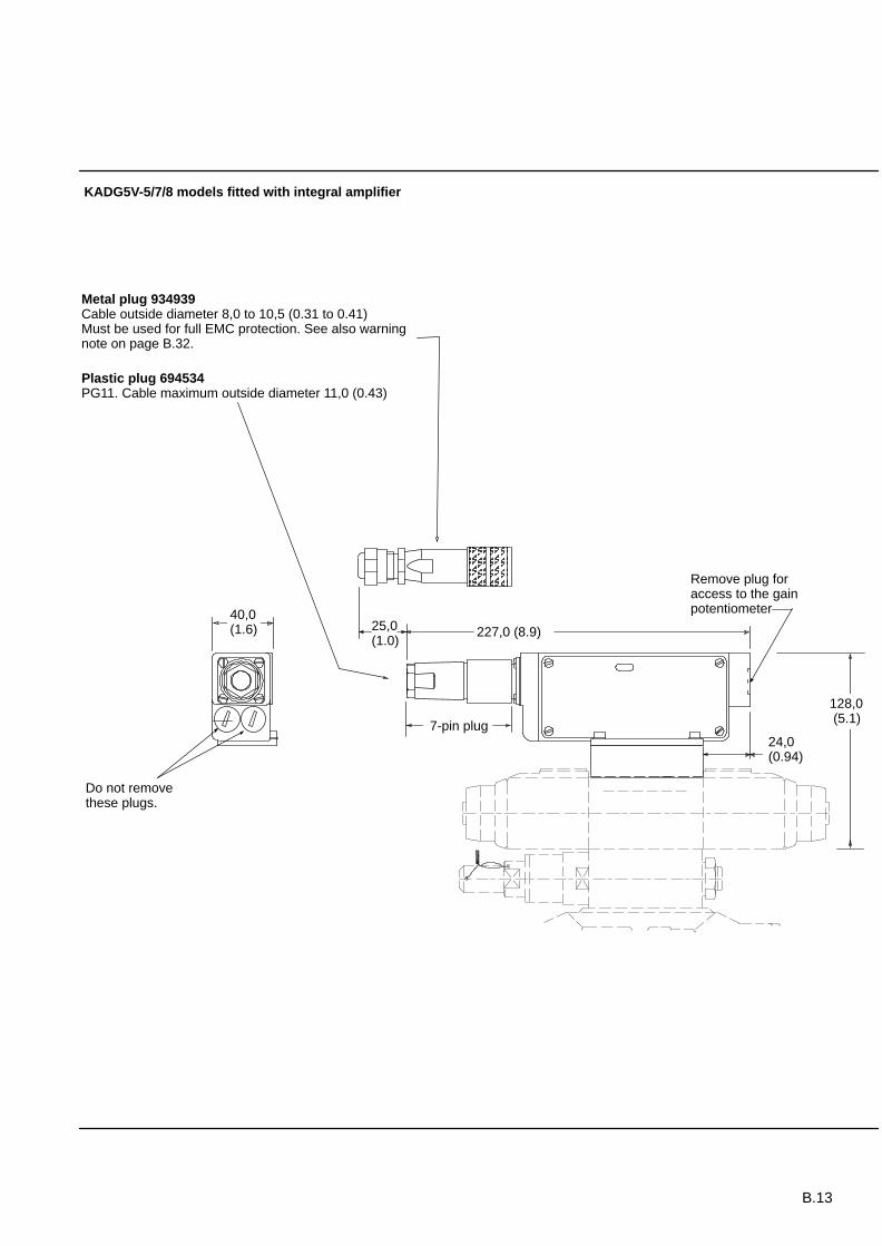
227,0 (8.9)
7-pin plug
Remove plug foraccess to the gainpotentiometer
Do not removethese plugs.
40,0(1.6)
ÂÂÂÂÂÂÂÂ
Metal plug 934939Cable outside diameter 8,0 to 10,5 (0.31 to 0.41)Must be used for full EMC protection. See also warningnote on page B.32.
Plastic plug 694534PG11. Cable maximum outside diameter 11,0 (0.43)
25,0(1.0)
KADG5V-5/7/8 models fitted with integral amplifier
24,0(0.94)
128,0 (5.1)
B.14
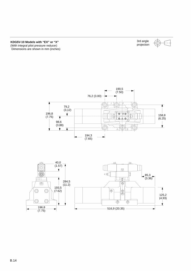
194,3(7.65)
76,2 (3.00)
190,5(7.50)
KDG5V-10 Models with “EX” or “X”(With integral pilot pressure reducer)
85,3(3.36)
516,9 (20.35)
125,2(4.93)
284,5(11.2)
193,5(7.62)
40,0 (1.57)
196,8(7.75)
3rd angleprojection
Dimensions are shown in mm (inches)
158,8(6.25)
196,8(7.75)
98,6(3.88)
79,2(3.12)
B.15
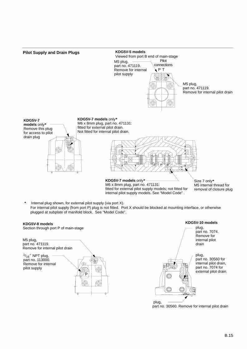
plug,part no. 7074.Remove forinternal pilotdrain
Pilot Supply and Drain Plugs
M5 plug,part no. 471119.Remove for internal pilot drain
M5 plug,part no. 471119.Remove for internalpilot supply
1/16 NPT plug,part no. 113000.Remove for internalpilot supply
M5 plug,part no. 471119.Remove for internal pilot drain
Pilotconnections
P T
P
KDG5V-8 modelsSection through port P of main-stage
KDG5V-5 modelsViewed from port B end of main-stage
plug,part no. 30560 forinternal pilot drain,part no. 7074 forexternal pilot drain.
plug,part no. 30560. Remove for internal pilot drain
KDG5V-10 models
KDG5V-7models only*Remove this plugfor access to pilotdrain plug
KDG5V-7 models only*M6 x 8mm plug, part no. 471131:fitted for external pilot drain.Not fitted for internal pilot drain.
KDG5V-7 models only* M6 x 8mm plug, part no. 471131:fitted for external pilot supply models; not fitted forinternal pilot supply models. See “Model Code” .
Size 7 only*M5 internal thread forremoval of closure plug
PA B
* Internal plug shown, for external pilot supply (via port X).For internal pilot supply (from port P) plug is not fitted. Port X should be blocked at mounting interface, or otherwiseplugged at subplate of manifold block. See “Model Code”.
B.16
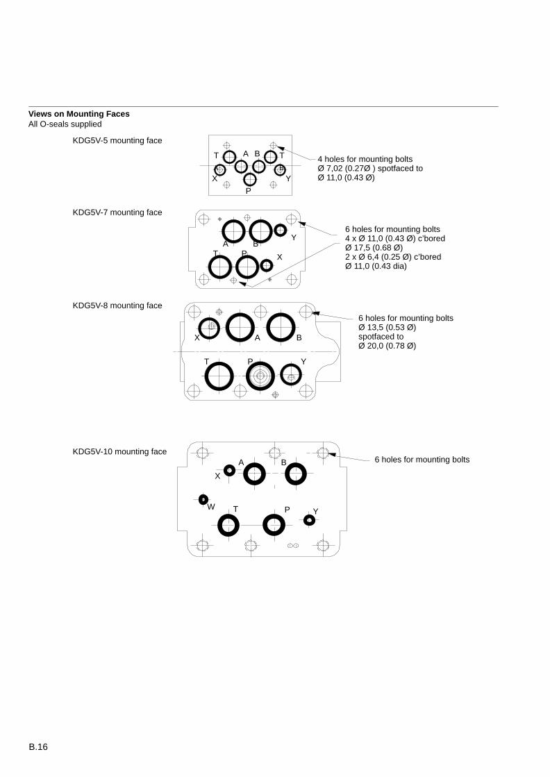
Views on Mounting FacesAll O-seals supplied
4 holes for mounting boltsØ 7,02 (0.27Ø ) spotfaced toØ 11,0 (0.43 Ø)
6 holes for mounting boltsØ 13,5 (0.53 Ø)spotfaced toØ 20,0 (0.78 Ø)
6 holes for mounting bolts4 x Ø 11,0 (0.43 Ø) c’boredØ 17,5 (0.68 Ø)2 x Ø 6,4 (0.25 Ø) c’bored Ø 11,0 (0.43 dia)
TA
TB
A B
A
A
B
B
P
P
P
T
T
X
X
Y
Y
X Y
KDG5V-5 mounting face
KDG5V-7 mounting face
KDG5V-8 mounting face
KDG5V-10 mounting faceA B
PT
X
YW
6 holes for mounting bolts
B.17
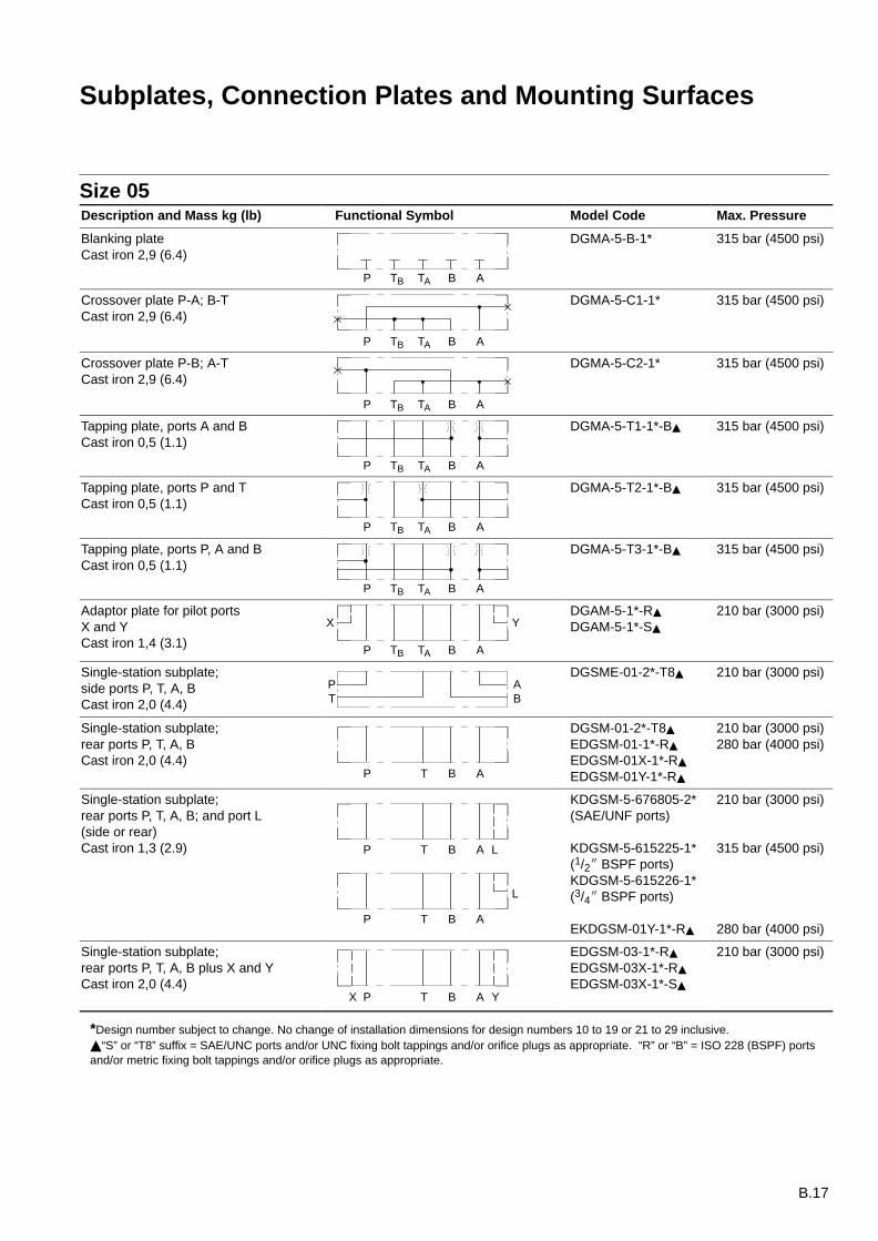
Subplates, Connection Plates and Mounting Surfaces
Size 05Description and Mass kg (lb) Functional Symbol Model Code Max. Pressure
Blanking plateCast iron 2,9 (6.4)
P TATB B A
DGMA-5-B-1* 315 bar (4500 psi)
Crossover plate P-A; B-TCast iron 2,9 (6.4)
P TATB B A
DGMA-5-C1-1* 315 bar (4500 psi)
Crossover plate P-B; A-TCast iron 2,9 (6.4)
P TATB B A
DGMA-5-C2-1* 315 bar (4500 psi)
Tapping plate, ports A and BCast iron 0,5 (1.1)
P TATB B A
DGMA-5-T1-1*-B 315 bar (4500 psi)
Tapping plate, ports P and TCast iron 0,5 (1.1)
P TATB B A
DGMA-5-T2-1*-B 315 bar (4500 psi)
Tapping plate, ports P, A and BCast iron 0,5 (1.1)
P TATB B A
DGMA-5-T3-1*-B 315 bar (4500 psi)
Adaptor plate for pilot portsX and YCast iron 1,4 (3.1)
YX
P TATB B A
DGAM-5-1*-R
DGAM-5-1*-S
210 bar (3000 psi)
Single-station subplate;side ports P, T, A, BCast iron 2,0 (4.4)
PT
AB
DGSME-01-2*-T8 210 bar (3000 psi)
Single-station subplate;rear ports P, T, A, BCast iron 2,0 (4.4)
P T B A
DGSM-01-2*-T8
EDGSM-01-1*-R
EDGSM-01X-1*-R
EDGSM-01Y-1*-R
210 bar (3000 psi)280 bar (4000 psi)
Single-station subplate;rear ports P, T, A, B; and port L(side or rear)Cast iron 1,3 (2.9) P T B A L
L
P T B A
KDGSM-5-676805-2*(SAE/UNF ports)
KDGSM-5-615225-1*(1/2 BSPF ports)KDGSM-5-615226-1*(3/4 BSPF ports)
EKDGSM-01Y-1*-R
210 bar (3000 psi)
315 bar (4500 psi)
280 bar (4000 psi)
Single-station subplate;rear ports P, T, A, B plus X and YCast iron 2,0 (4.4)
YX P T B A
EDGSM-03-1*-R
EDGSM-03X-1*-R
EDGSM-03X-1*-S
210 bar (3000 psi)
*Design number subject to change. No change of installation dimensions for design numbers 10 to 19 or 21 to 29 inclusive.“S” or “T8” suffix = SAE/UNC ports and/or UNC fixing bolt tappings and/or orifice plugs as appropriate. “R” or “B” = ISO 228 (BSPF) portsand/or metric fixing bolt tappings and/or orifice plugs as appropriate.
B.18
Sizes 07 and 08Description and Mass kg (lb) Functional Symbol Model Code Max. Pressure
Single-station subplateCast iron 3,8 (8.4)Cast iron 3,8 (8.4)Cast iron 6,1 (13.4)Cast iron 5,0 (11)Cast iron 5,0 (11)Cast iron 13 (28.6)
YX P T B AL
DGSM-04EDGVM-7XEDGVM-7Y/7ZDGSM-8EDGVM-8XEDGVM-8Y/8Z
210 bar (3000 psi)350 bar (5000 psi)350 bar (5000 psi)210 bar (3000 psi)350 bar (5000 psi)350 bar (5000 psi)
General Description
When a subplate is not used, amachined pad must be provided forvalve mounting. Pad must be flat within0,127 mm (.0005 inch) and smoothwithin 1,6 µm (63 microinch). Mountingbolts, when provided by customer,should be SAE grade 7 or better.
Dimensional TolerancesDimensional tolerance on interfacedrawings is 0,2 mm (0.008”) exceptwhere otherwise stated.
ISO 4401 specifies inch conversion to0.01”.
Conversion from MetricISO 4401 gives dimensions in mm. Inchconversions are accurate to 0.01” unlessotherwise stated.
Mounting Bolt TappingsISO 4401 gives metric thread tappings.Alternate UNC tappings are Vickers
recommendations that allow theseplates and associated valves to be usedup to their maximum pressures, whenusing Vickers recommended bolt kits, orbolts of an equivalent strength (seepage B.38). It is recommended thatCustomer’s own manifold blocks forUNC bolts should be tapped to theminimum depths given in the footnotes.
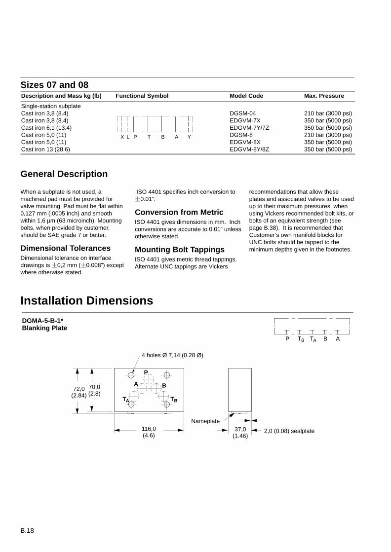
Installation Dimensions
P
A B
TA TB
4 holes Ø 7,14 (0.28 Ø)
P TATB B A
70,0(2.8)
2,0 (0.08) sealplate37,0(1.46)
116,0(4.6)
72,0(2.84)
Nameplate
DGMA-5-B-1*Blanking Plate
B.19
A
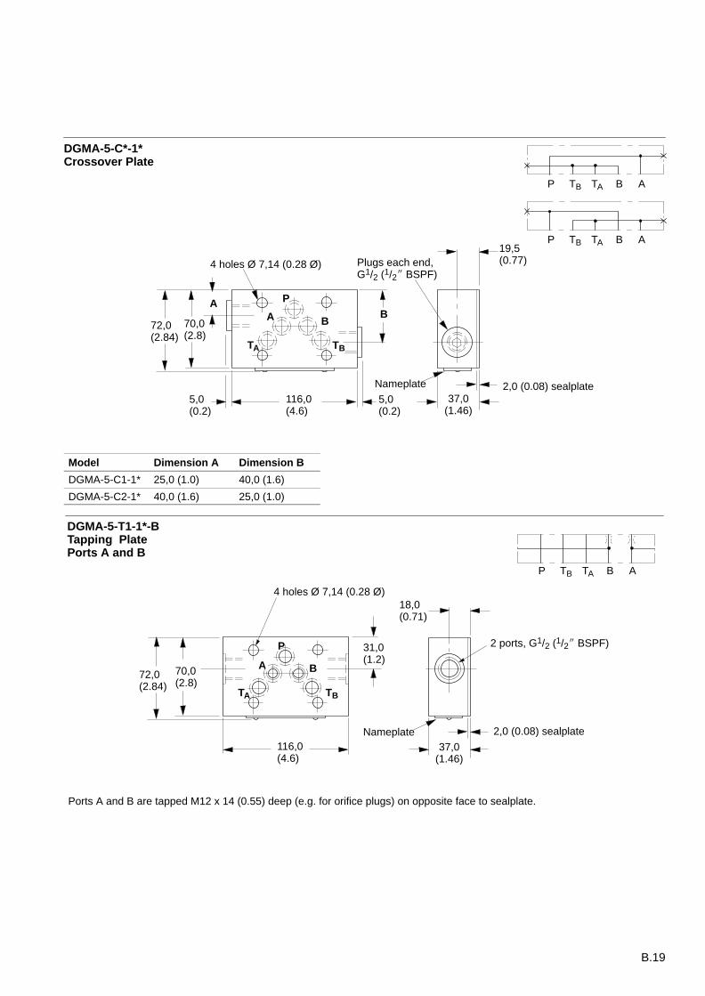
DGMA-5-C*-1* Crossover Plate
P TATB B A
P TATB B A
P
A B
TA
4 holes Ø 7,14 (0.28 Ø)
70,0(2.8)
2,0 (0.08) sealplate37,0
(1.46)116,0(4.6)
72,0(2.84)
B
TB
Nameplate
Plugs each end, G1/2 (1/2 BSPF)
5,0(0.2)
5,0(0.2)
19,5(0.77)
Model Dimension A Dimension B
DGMA-5-C1-1* 25,0 (1.0) 40,0 (1.6)
DGMA-5-C2-1* 40,0 (1.6) 25,0 (1.0)
P
A B
TA TB
4 holes Ø 7,14 (0.28 Ø)
70,0(2.8)
2,0 (0.08) sealplate
37,0(1.46)
116,0(4.6)
72,0(2.84)
31,0(1.2)
18,0 (0.71)
2 ports, G1/2 (1/2 BSPF)
Nameplate
Ports A and B are tapped M12 x 14 (0.55) deep (e.g. for orifice plugs) on opposite face to sealplate.
P TATB B A
DGMA-5-T1-1*-B Tapping PlatePorts A and B

B.20
45,0(1.8)
2,0 (0.08) sealplate
P
A B
TA TB
DGMA-5-T2-1*-B Tapping PlatePorts P and T
4 holes Ø 7,14 (0.28 Ø)
70,0(2.8)
37,0(1.46)
116,0(4.6)
72,0(2.84)
Nameplate
28,0(1.1)
18,0(0.71)
2 ports, G1/2 (1/2 BSPF)
Ports P and TA are tapped M12 x 14 (0.55) deep (e.g. for orifice plugs) on opposite face to sealplate.
P TATB B A
A B
TA TB
4 holes Ø 7,14 (0.28 Ø)
70,0(2.8)
2,0 (0.08) sealplate37,0(1.46)
116,0(4.6)
Nameplate
31,0(1.2)
18,0(0.71)
3 ports, G1/2 (1/2 BSPF)
Ports P, A and B are tapped M12 x 14 (0.55) deep (e.g. for orifice plugs) on opposite face to sealplate.
P
72,0(2.84)
DGMA-5-T3-1*-B Tapping PlatePorts P, A and B
P TATB B A
B.21
70,0(2.8)
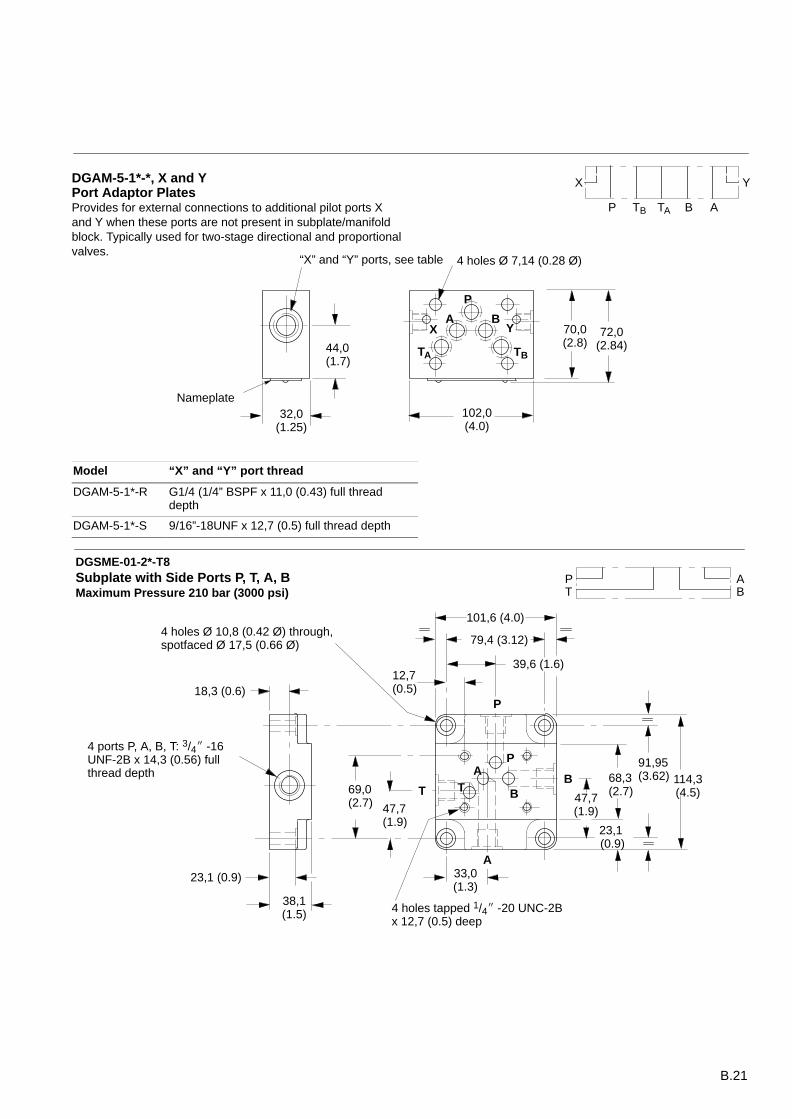
DGAM-5-1*-*, X and Y Port Adaptor PlatesProvides for external connections to additional pilot ports Xand Y when these ports are not present in subplate/manifoldblock. Typically used for two-stage directional and proportionalvalves.
P
A B
TA TB
4 holes Ø 7,14 (0.28 Ø)
32,0(1.25)
102,0(4.0)
72,0(2.84)44,0
(1.7)
Nameplate
YX
P TATB B A
“X” and “Y” ports, see table
X Y
Model “X” and “Y” port thread
DGAM-5-1*-R G1/4 (1/4” BSPF x 11,0 (0.43) full threaddepth
DGAM-5-1*-S 9/16”-18UNF x 12,7 (0.5) full thread depth
47,7(1.9)
23,1 (0.9)
39,6 (1.6)
79,4 (3.12)
101,6 (4.0)
PT
AB
PA
BT
23,1 (0.9)
38,1(1.5)
12,7(0.5)
47,7(1.9)
68,3(2.7)
18,3 (0.6)
69,0(2.7)
4 holes Ø 10,8 (0.42 Ø) through,spotfaced Ø 17,5 (0.66 Ø)
4 ports P, A, B, T: 3/4 -16UNF-2B x 14,3 (0.56) fullthread depth
4 holes tapped 1/4 -20 UNC-2Bx 12,7 (0.5) deep
91,95(3.62) 114,3
(4.5)
33,0(1.3)
P
B
A
T
Subplate with Side Ports P, T, A, BMaximum Pressure 210 bar (3000 psi)
DGSME-01-2*-T8
B.22
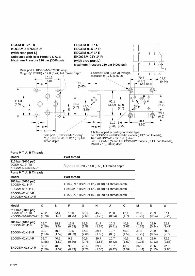
Rear port L, KDGSM-5-676805 only:G1/8 (1/8 BSPF) x 12,0 (0.47) full thread depth
79,4(3.12)
90,4(3.56)
M11,2
(0.44)
C
101,6(4.0)
11,5(0.45)
PA B
T
N
12,7 (0.5)
68,3(2.7)
23,1(0.9)
11,2(0.44)
4 holes Ø 10,8 (0.42 Ø) through,spotfaced Ø 17,5 (0.66 Ø)
4 holes tapped according to model type:For DGSM-01 and KDGSM-5 models (UNC port threads),1/4 -20 UNC-2B x 12,7 (0.5) deep.For EDGSM-01(*) and EKDGSM-01Y models (BSPF port threads),M6-6H x 15,8 (0.62) deep.
92,1(3.62)
114,3(4.5)
P T B A
P T B A L
L
P T B A
L
WK E
69,0(2.7)
F
68,3(2.7) 47,5
(1.5)
HJ
G
5,6(0.22)
Side port L, EKDGSM-01Y only:9/16 -18 UNF-2B x 12,7 (0.5) fullthread depth
Maximum Pressure 280 bar (4000 psi)
Subplates with Rear Ports P, T, A, BMaximum Pressure 210 bar (3000 psi)
DGSM-01-2*-T8KDGSM-5-676805-2* (with rear port L)
EDGSM-01-1*-REDGSM-01X-1*-REDGSM-01Y-1*-REKDGSM-01Y-1*-R (with side port L)
Ports P, T, A, B Threads
Model Port thread
210 bar (3000 psi)DGSM-01-2*-T8KDGSM-5-676805-2*
3/4-16 UNF-2B x 14,0 (0.56) full thread depth
Ports P, T, A, B Threads
Model Port thread
280 bar (4000 psi)EDGSM-01-1*-R G1/4 (1/4 BSPF) x 12,2 (0.48) full thread depth
EDGSM-01X-1*-R G3/8 (3/8 BSPF) x 12,2 (0.48) full thread depth
EDGSM-01Y-1*-REKDGSM-01Y-1*-R
G1/2 (1/2 BSPF) x 15,0 (0.59) full thread depth
Model C E F G H J K M N W
210 bar (3000 psi)DGSM-01-2*-T8KDGSM-5-676805-2*
45,2(1.78)
42,1 (1.7)
19,0(0.75)
68,3(2.69)
45,2(1.78)
23,8(0.94)
42,1(1.7)
31,8(1.25)
23,9(0.94)
57,1(2.25)
280 bar (4000 psi)EDGSM-01-1*-R 39,7
(1.56)38,1(1.5)
13,5(0.53)
65,5(2.58)
41,7(1.64)
10,3(0.41)
40,9(1.61)
31,8(1.25)
23,9(0.94)
62,7(2.47)
EDGSM-01X-1*-R 39,7(1.56)
40,5(1.59)
13,5(0.53)
67,5(2.66)
39,7(1.56)
12,7(0.5)
40,5(1.59)
31,8(1.25)
23,9(0.94)
68,6(2.7)
EDGSM-01Y-1*-R 39,7(1.56)
40,5(1.59)
9,9(0.39)
70,6(2.78)
39,7(1.56)
10,7(0.42)
40,5(1.59)
31,8(1.25)
28,6(1.13)
72,6(2.86)
EKDGSM-01Y-1*-R 39,7(1.56)
40,5(1.59)
9,9(0.39)
70,6(2.78)
39,7(1.56)
10,7(0.42)
40,5(1.59)
36,5(1.44)
28,6(1.13)
72,6(2.86)
B.23
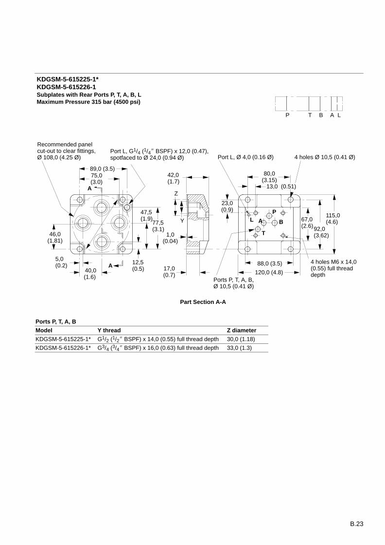
42,0(1.7)
75,0(3.0)
89,0 (3.5)
88,0 (3.5)
120,0 (4.8)
Subplates with Rear Ports P, T, A, B, LMaximum Pressure 315 bar (4500 psi)
KDGSM-5-615225-1*KDGSM-5-615226-1
LP T B A
P
A B
T
80,0(3.15)
67,0(2.6)
4 holes M6 x 14,0(0.55) full threaddepth
115,0(4.6)L
46,0(1.81)
77,5(3.1)
Port L, G1/4 (1/4 BSPF) x 12,0 (0.47),spotfaced to Ø 24,0 (0.94 Ø)
23,0(0.9)
92,0(3.62)
17,0(0.7)
47,5(1.9)
12,5(0.5)
Z
Y
Port L, Ø 4,0 (0.16 Ø)
Ports P, T, A, B,Ø 10,5 (0.41 Ø)
Part Section A-A
40,0(1.6)
5,0(0.2) A
A
Recommended panelcut-out to clear fittings,Ø 108,0 (4.25 Ø) 4 holes Ø 10,5 (0.41 Ø)
13,0 (0.51)
1,0(0.04)
Ports P, T, A, B
Model Y thread Z diameter
KDGSM-5-615225-1* G1/2 (1/2 BSPF) x 14,0 (0.55) full thread depth 30,0 (1.18)
KDGSM-5-615226-1* G3/4 (3/4 BSPF) x 16,0 (0.63) full thread depth 33,0 (1.3)
B.24
111,1 (4.4)
136,6 (5.38)68,3(2.7)
41,3 (1.62)
PA B
T
134,9(5.3)
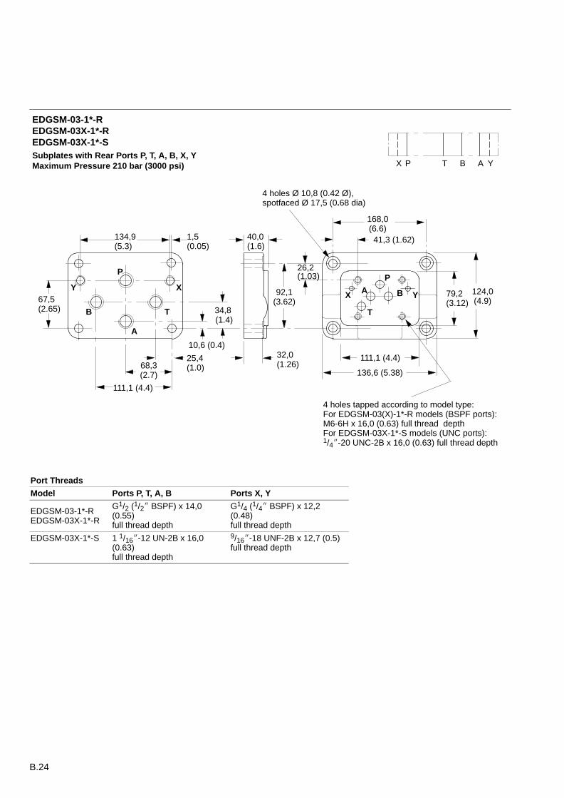
4 holes tapped according to model type:For EDGSM-03(X)-1*-R models (BSPF ports):M6-6H x 16,0 (0.63) full thread depthFor EDGSM-03X-1*-S models (UNC ports):1/4-20 UNC-2B x 16,0 (0.63) full thread depth
92,1(3.62)67,5
(2.65)
111,1 (4.4)
YX P T B A
168,0(6.6)
40,0(1.6)
124,0(4.9)
26,2 (1.03)
79,2(3.12)
32,0(1.26)
25,4(1.0)
34,8 (1.4)
10,6 (0.4)
X Y
4 holes Ø 10,8 (0.42 Ø),spotfaced Ø 17,5 (0.68 dia)
1,5(0.05)
XY
A
B T
P
Subplates with Rear Ports P, T, A, B, X, YMaximum Pressure 210 bar (3000 psi)
EDGSM-03-1*-REDGSM-03X-1*-REDGSM-03X-1*-S
Port Threads
Model Ports P, T, A, B Ports X, Y
EDGSM-03-1*-REDGSM-03X-1*-R
G1/2 (1/2 BSPF) x 14,0(0.55) full thread depth
G1/4 (1/4 BSPF) x 12,2(0.48) full thread depth
EDGSM-03X-1*-S 1 1/16-12 UN-2B x 16,0(0.63) full thread depth
9/16-18 UNF-2B x 12,7 (0.5) full thread depth
B.25
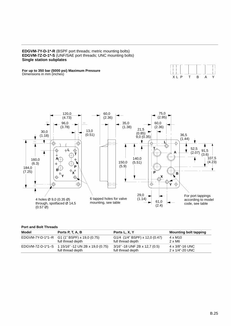
EDGVM-7Y-D-1*-R (BSPF port threads; metric mounting bolts)EDGVM-7Z-D-1*-S (UNF/SAE port threads; UNC mounting bolts)Single station subplates
75,0(2.95)
160,0(6.3)
P
TA
BX
Y
L
120,0(4.73)
30,0(1.18)
96,0(3.78)
13,0 (0.51)
35,0 (1.38)
60,0 (2.36)
150,0(5.9)
140,0(5.51)
9,0 (0.35)
21,5(0.85)
29,0 (1.14)
61,0(2.4)
60,0(2.36)
L
T
P B
A
Y
X
36,5(1.44)
52,5(2.07) 91,5
(3.6)107,5(4.23)
6 tapped holes for valve mounting, see table
For port tappings according to modelcode, see table
4 holes Ø 9,0 (0.35 Ø)through, spotfaced Ø 14,5(0.57 Ø)
184,0(7.25)
YX P T B AL
For up to 350 bar (5000 psi) Maximum PressureDimensions in mm (inches)
Port and Bolt Threads
Model Ports P, T, A, B Ports L, X, Y Mounting bolt tapping
EDGVM-7Y-D-1*1–R G1 (1” BSPF) x 19,0 (0.75)full thread depth
G1/4 (1/4” BSPF) x 12,0 (0.47)full thread depth
4 x M102 x M6
EDGVM-7Z-D-1*1–S 1 15/16” -12 UN 2B x 19,0 (0.75)full thread depth
3/16” -18 UNF 2B x 12,7 (0.5)full thread depth
4 x 3/8”-16 UNC2 x 1/4”-20 UNC
B.26
L
T P
BA
Y
X
For port tappings according to modelcode, see table
160,0(6.3)
69,9(2.75)
140,0(5.51)
12,6(0.5)
C
DE
M
K
J
H
G F
14,3 (0.65)
42,5 (1.67)
Ø 9,9 (0.389 Ø)
25,0(1.0)
Ø 14,5 (0.57 Ø)
92,0(3.62)
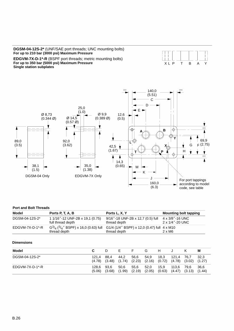
EDGVM-7X OnlyDGSM-04 Only
89,0(3.5)
38,1(1.5)
35,0(1.38)
Ø 8,73 (0.344 Ø)
YX P T B AL
DGSM-04-12S-2* (UNF/SAE port threads; UNC mounting bolts)For up to 210 bar (3000 psi) Maximum Pressure
EDGVM-7X-D-1*-R (BSPF port threads; metric mounting bolts)For up to 350 bar (5000 psi) Maximum PressureSingle station subplates
Port and Bolt Threads
Model Ports P, T, A, B Ports L, X, Y Mounting bolt tapping
DGSM-04-12S-2* 1 1/16-12 UNF-2B x 19,1 (0.75)full thread depth
9/16-18 UNF-2B x 12,7 (0.5) fullthread depth
4 x 3/8-16 UNC2 x 1/4-20 UNC
EDGVM-7X-D-1*-R G3/4 (3/4 BSPF) x 16,0 (0.63) fullthread depth
G1/4 (1/4 BSPF) x 12,0 (0.47) fullthread depth
4 x M102 x M6
Dimensions
Model C D E F G H J K M
DGSM-04-12S-2* 121,4(4.78)
88,4(3.48)
44,2(1.74)
56,6(2.23)
54,9(2.16)
18,3(0.72)
121,4(4.78)
76,7(3.02)
32,3(1.27)
EDGVM-7X-D-1*-R 128,6(5.06)
93,6(3.68)
50,6(1.99)
55,6(2.19)
52,0(2.05)
15,9(0.63)
113,6(4.47)
79,6(3.13)
36,6(1.44)
B.27
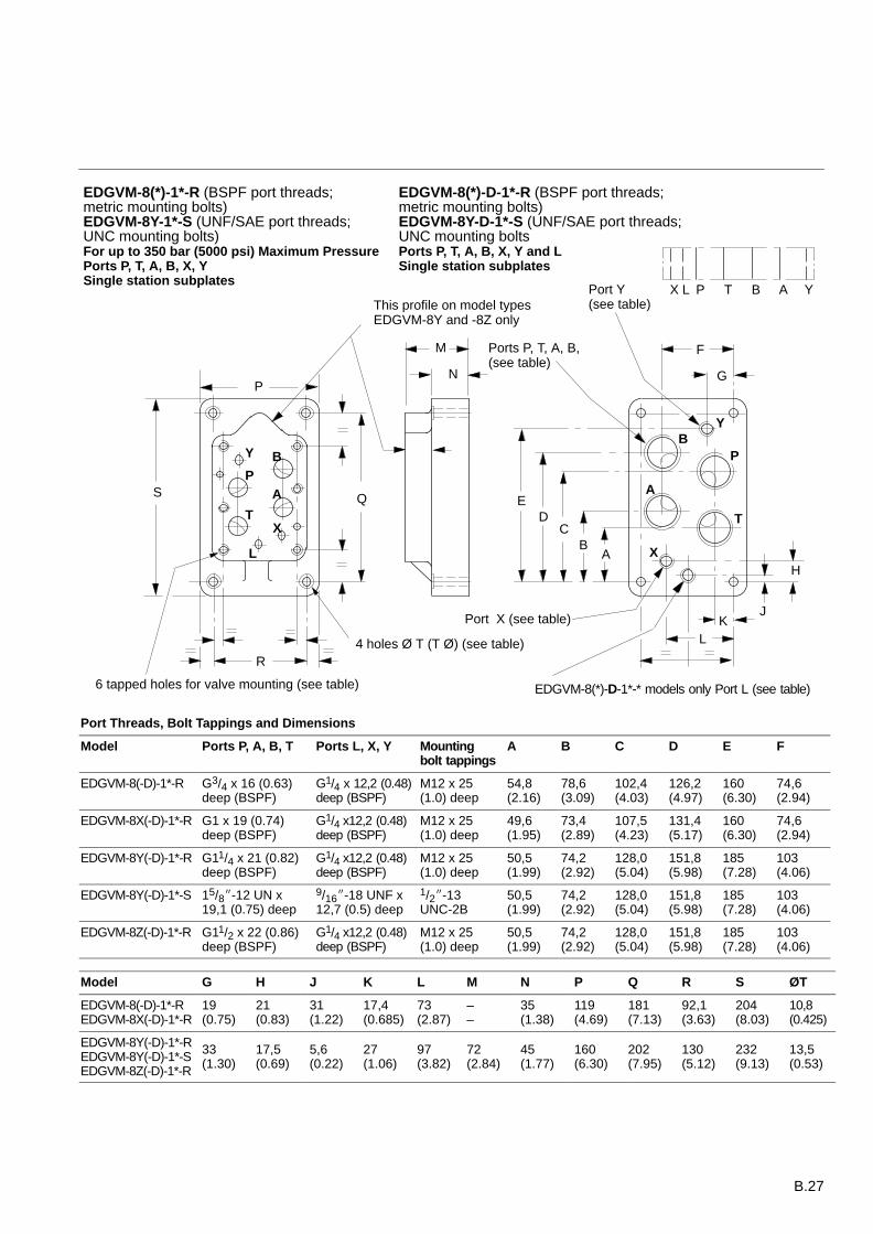
EDGVM-8(*)-D-1*-R (BSPF port threads; metric mounting bolts)EDGVM-8Y-D-1*-S (UNF/SAE port threads; UNC mounting boltsPorts P, T, A, B, X, Y and LSingle station subplates
L
M
X
6 tapped holes for valve mounting (see table)
4 holes Ø T (T Ø) (see table)R
B
T
P
A
Y
K
F
G
AB
CD
H
J
QS
P
E
N
This profile on model typesEDGVM-8Y and -8Z only
Port Y(see table)
Ports P, T, A, B, (see table)
Port X (see table)
EDGVM-8(*)-D-1*-* models only Port L (see table)
Y B
A
L
T
P
X
YX P T B AL
EDGVM-8(*)-1*-R (BSPF port threads; metric mounting bolts)EDGVM-8Y-1*-S (UNF/SAE port threads; UNC mounting bolts)For up to 350 bar (5000 psi) Maximum PressurePorts P, T, A, B, X, YSingle station subplates
Port Threads, Bolt Tappings and Dimensions
Model Ports P, A, B, T Ports L, X, Y Mountingbolt tappings
A B C D E F
EDGVM-8(-D)-1*-R G3/4 x 16 (0.63) deep (BSPF)
G1/4 x 12,2 (0.48)deep (BSPF)
M12 x 25(1.0) deep
54,8 (2.16)
78,6 (3.09)
102,4(4.03)
126,2(4.97)
160(6.30)
74,6(2.94)
EDGVM-8X(-D)-1*-R G1 x 19 (0.74)deep (BSPF)
G1/4 x12,2 (0.48)deep (BSPF)
M12 x 25(1.0) deep
49,6(1.95)
73,4(2.89)
107,5(4.23)
131,4(5.17)
160(6.30)
74,6(2.94)
EDGVM-8Y(-D)-1*-R G11/4 x 21 (0.82)deep (BSPF)
G1/4 x12,2 (0.48)deep (BSPF)
M12 x 25(1.0) deep
50,5(1.99)
74,2(2.92)
128,0(5.04)
151,8(5.98)
185(7.28)
103(4.06)
EDGVM-8Y(-D)-1*-S 15/8-12 UN x19,1 (0.75) deep
9/16-18 UNF x12,7 (0.5) deep
1/2-13UNC-2B
50,5(1.99)
74,2(2.92)
128,0(5.04)
151,8(5.98)
185(7.28)
103(4.06)
EDGVM-8Z(-D)-1*-R G11/2 x 22 (0.86)deep (BSPF)
G1/4 x12,2 (0.48)deep (BSPF)
M12 x 25(1.0) deep
50,5(1.99)
74,2(2.92)
128,0(5.04)
151,8(5.98)
185(7.28)
103(4.06)
Model G H J K L M N P Q R S ØT
EDGVM-8(-D)-1*-REDGVM-8X(-D)-1*-R
19(0.75)
21(0.83)
31(1.22)
17,4(0.685)
73(2.87)
––
35(1.38)
119(4.69)
181(7.13)
92,1(3.63)
204(8.03)
10,8(0.425)
EDGVM-8Y(-D)-1*-REDGVM-8Y(-D)-1*-SEDGVM-8Z(-D)-1*-R
33(1.30)
17,5(0.69)
5,6(0.22)
27(1.06)
97(3.82)
72(2.84)
45(1.77)
160(6.30)
202(7.95)
130(5.12)
232(9.13)
13,5(0.53)
B.28
73,0 (2.7)
181,0(7.12)
102,4(4.03)
126,2(4.97)
78,5(3.09)
54,9(2.16)
P
T
A
B
X
17,5 (0.69)
35,0 (1.38)
114,0(4.5)
203,0(8.0)
19,0(0.75)
74,6(2.94)
138,2(5.44)
92,0(3.62)
42,9(1.69)
6 holes tapped 1/2-13 UNC-2B
4 holes through Ø10,3 (0.406 Ø)
Y
YX P T B AL
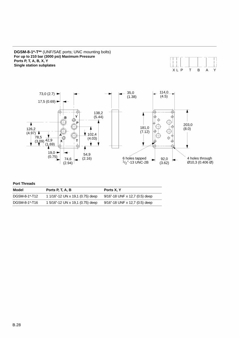
DGSM-8-1*-T** (UNF/SAE ports; UNC mounting bolts)For up to 210 bar (3000 psi) Maximum PressurePorts P, T, A, B, X, YSingle station subplates
Port Threads
Model Ports P, T, A, B Ports X, Y
DGSM-8-1*-T12 1 1/16”-12 UN x 19,1 (0.75) deep 9/16”-18 UNF x 12,7 (0.5) deep
DGSM-8-1*-T16 1 5/16”-12 UN x 19,1 (0.75) deep 9/16”-18 UNF x 12,7 (0.5) deep
B.29
46,0(1.181)
153,0 (6.02) min.
100,8 (3.968)
112,7 (4.437)
130,2 0,1(5.126 0.004)
130,0 (5.12)min.
50,0(1.97)
101,6 0,1(4.0 0.004)
2 holes Ø 4,0 (0.157 Ø)x 8,0 (0.31) min. depth
4 holes M10 x 17,0(0.67) min. full threaddepth
2 holes M6-6H x 17,0(0.67) min. full threaddepth
3 holes (ports L, X, Y)Ø 6,3 (0.25 Ø) max. 4 holes (ports P, T, A, B)
Ø 17,5 (0.69 Ø) max.
95,0(3.74) min.
18,3(0.72)
34,1(1.34)
65,9(2.59)
76,6(3.016)
88,1(3.47)
1,6 0,1(0.063 0.004)
14,3(0.56)
15,9 (0.63)
71,50,1
(2.815 0.004)
PT
A B
X
Y
L
11,0(0.43)
69,80,1
(2.75 0.004)
57,2(2.25)
55,6(2.19)
34,9(1.38)
3/8-16 UNC optional. 1/4-20 UNC optional.
2 holes Ø 7,5 (0.295 Ø) x8,0 (0.31) min. depth
6 holes, M12-6H x 20,0 (0.78) min. full thread depth
5,6 (0.22)
17,5 (0.689)29,4 0,1 (1.157 0.004)
53,2 0,1 (2.094 0.004)
94,5 0,1 (3.720 0.004)77,0 (3.03)
92,1 0,1(3.626 0.004)
74,6(2.937)
73,0(2.874)
19,0 (0.748)
17,4 (0.685)
118,0(4.65) min.
4,8 0,1 (0.189 0.004)
Ports X,Y:Ø 11,2 (0.44 Ø) max.
Port L:Ø 11,2 (0.44 Ø) max.
Ports P, T, A, B:Ø 23,4 (0.92 Ø) max.
PT
A BX
Y
L
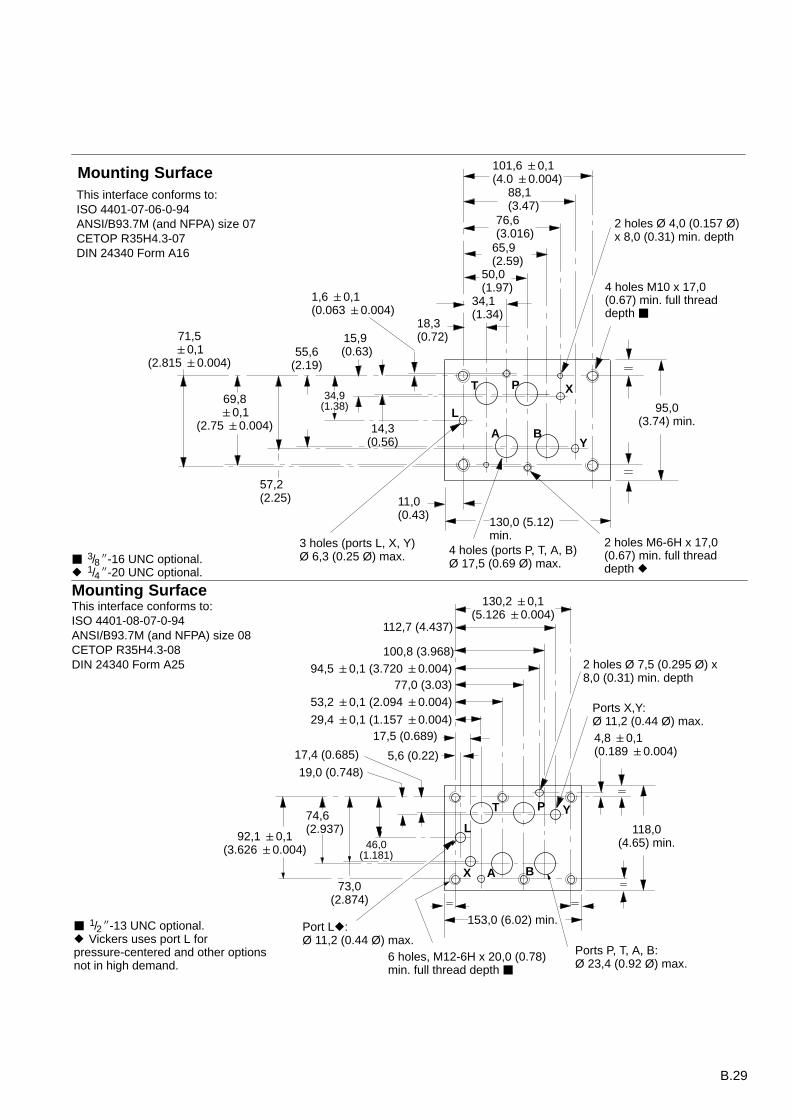
Mounting SurfaceThis interface conforms to:ISO 4401-08-07-0-94ANSI/B93.7M (and NFPA) size 08CETOP R35H4.3-08DIN 24340 Form A25
1/2-13 UNC optional. Vickers uses port L forpressure-centered and other optionsnot in high demand.
Mounting SurfaceThis interface conforms to:ISO 4401-07-06-0-94ANSI/B93.7M (and NFPA) size 07CETOP R35H4.3-07DIN 24340 Form A16
B.30
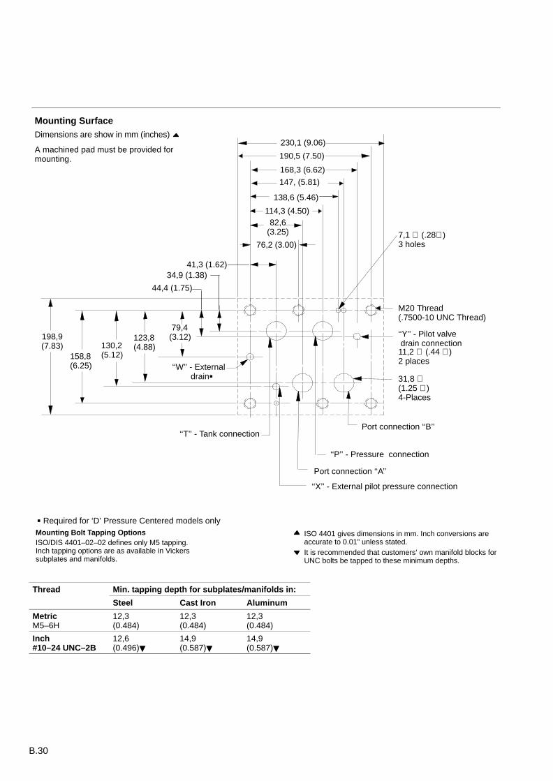
Dimensions are show in mm (inches)
A machined pad must be provided formounting.
198,9(7.83)
158,8 (6.25)
130,2 (5.12)
123,8 (4.88)
79,4 (3.12)
82,6(3.25)
138,6 (5.46)
230,1 (9.06)
190,5 (7.50)
168,3 (6.62)
114,3 (4.50)
76,2 (3.00)
M20 Thread(.7500-10 UNC Thread)
31,8 ∅ (1.25 ∅ )4-Places
‘‘X’’ - External pilot pressure connection
Port connection ‘‘A’’
Port connection ‘‘B’’
‘‘P’’ - Pressure connection
‘‘T’’ - Tank connection
‘‘Y’’ - Pilot valve drain connection
‘‘W’’ - External drain
Mounting Bolt Tapping OptionsISO/DIS 4401–02–02 defines only M5 tapping.Inch tapping options are as available in Vickerssubplates and manifolds.
ISO 4401 gives dimensions in mm. Inch conversions areaccurate to 0.01” unless stated.It is recommended that customers’ own manifold blocks forUNC bolts be tapped to these minimum depths.
7,1 ∅ (.28∅ ) 3 holes
11,2 ∅ (.44 ∅ )2 places
41,3 (1.62)34,9 (1.38)
44,4 (1.75)
Required for ‘D’ Pressure Centered models only
Mounting Surface
147, (5.81)
Thread Min. tapping depth for subplates/manifolds in:
Steel Cast Iron Aluminum
MetricM5–6H
12,3(0.484)
12,3(0.484)
12,3(0.484)
Inch#10–24 UNC–2B
12,6(0.496)
14,9(0.587)
14,9(0.587)
B.31
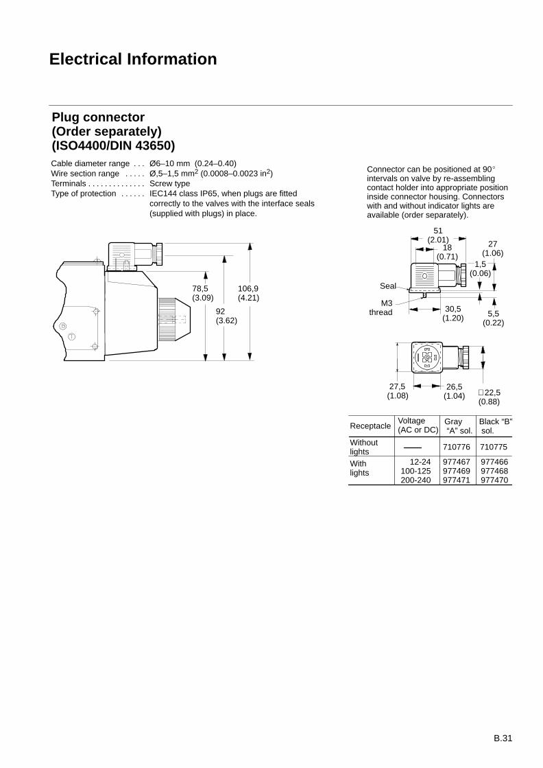
Electrical Information
1,5(0.06)
Seal
51(2.01) 27
(1.06)
∅ 22,5(0.88)
M3thread 5,5
(0.22)
30,5(1.20)
26,5(1.04)
18(0.71)
Connector can be positioned at 90intervals on valve by re-assemblingcontact holder into appropriate positioninside connector housing. Connectorswith and without indicator lights areavailable (order separately).
Voltage(AC or DC)
Gray “A” sol.
Black “B” sol.
12-24100-125200-240
977467977469977471
977466977468977470
710775710776Withoutlights
Withlights
Receptacle
78,5(3.09)
92(3.62)
106,9(4.21)
Plug connector (Order separately) (ISO4400/DIN 43650)Cable diameter range Ø6–10 mm (0.24–0.40). . . Wire section range Ø,5–1,5 mm2 (0.0008–0.0023 in2). . . . . Terminals Screw type. . . . . . . . . . . . . . Type of protection IEC144 class IP65, when plugs are fitted . . . . . .
correctly to the valves with the interface seals (supplied with plugs) in place.
27,5 (1.08)
B.32
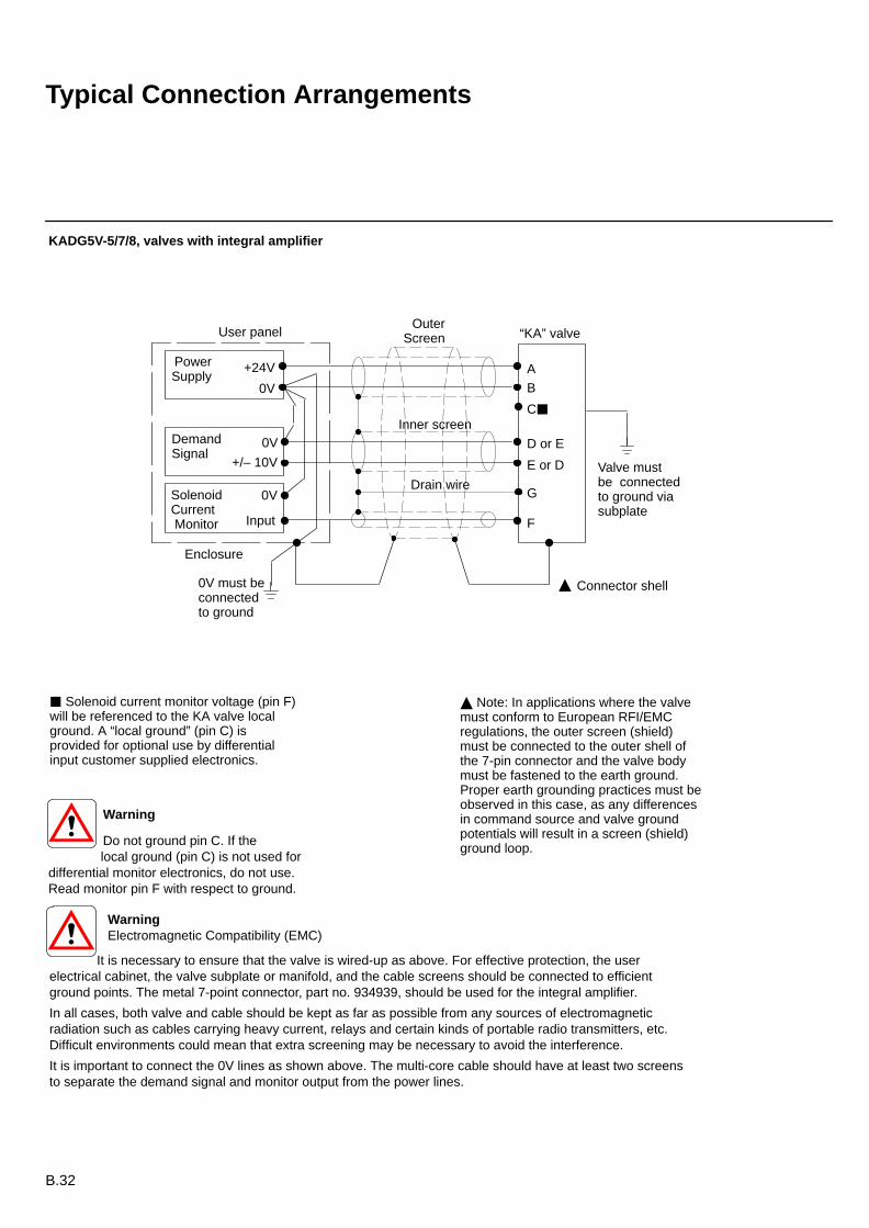
Typical Connection Arrangements
Warning
Do not ground pin C. If the local ground (pin C) is not used fordifferential monitor electronics, do not use.Read monitor pin F with respect to ground.
User panelOuter
Screen “KA” valve
AB
F
G
D or E
E or D
C
+24V
0V
DemandSignal
SolenoidCurrent Monitor
PowerSupply
Enclosure
Valve mustbe connectedto ground viasubplate
0V
Input
+/– 10V
0V
Connector shell
Solenoid current monitor voltage (pin F)will be referenced to the KA valve localground. A “local ground” (pin C) isprovided for optional use by differentialinput customer supplied electronics.
KADG5V-5/7/8, valves with integral amplifier
Note: In applications where the valvemust conform to European RFI/EMCregulations, the outer screen (shield)must be connected to the outer shell ofthe 7-pin connector and the valve bodymust be fastened to the earth ground.Proper earth grounding practices must beobserved in this case, as any differencesin command source and valve groundpotentials will result in a screen (shield)ground loop.
0V must beconnectedto ground
Warning Electromagnetic Compatibility (EMC)
It is necessary to ensure that the valve is wired-up as above. For effective protection, the userelectrical cabinet, the valve subplate or manifold, and the cable screens should be connected to efficientground points. The metal 7-point connector, part no. 934939, should be used for the integral amplifier.
In all cases, both valve and cable should be kept as far as possible from any sources of electromagneticradiation such as cables carrying heavy current, relays and certain kinds of portable radio transmitters, etc.Difficult environments could mean that extra screening may be necessary to avoid the interference.
It is important to connect the 0V lines as shown above. The multi-core cable should have at least two screensto separate the demand signal and monitor output from the power lines.
Drain wire
Inner screen
KADG5V5-5/7/8, valves with integral amplifier
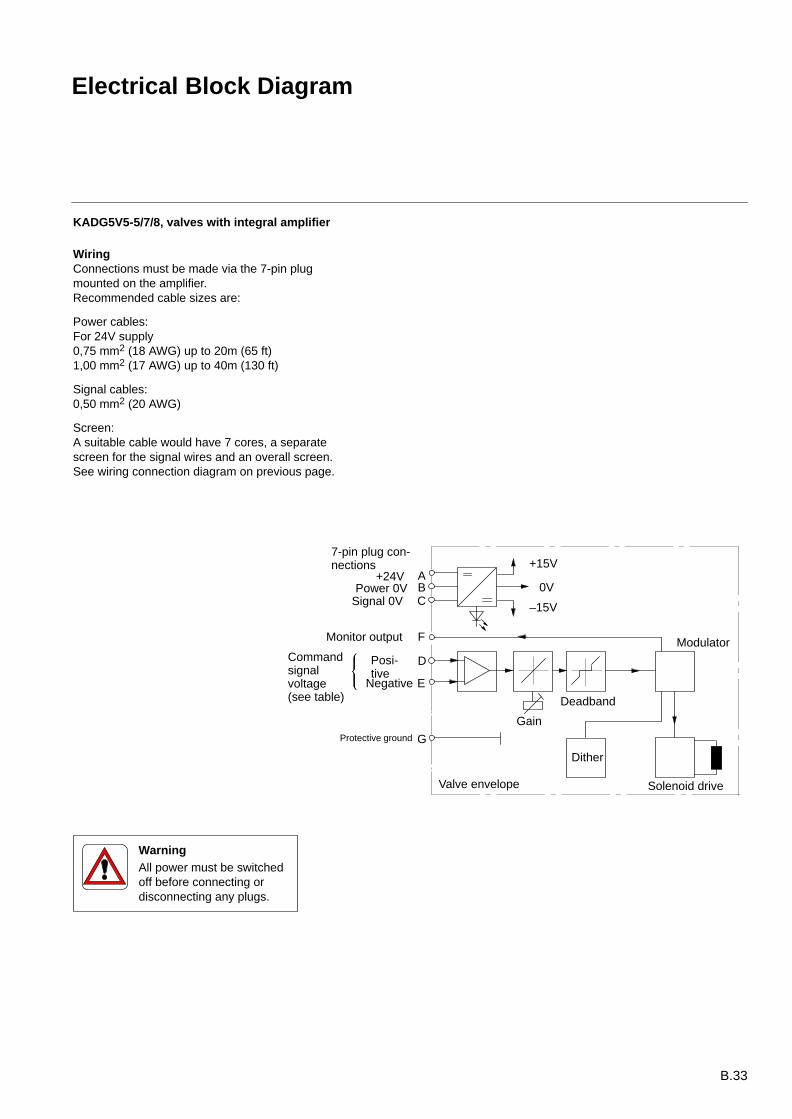
WiringConnections must be made via the 7-pin plugmounted on the amplifier.Recommended cable sizes are:
Power cables:For 24V supply0,75 mm2 (18 AWG) up to 20m (65 ft)1,00 mm2 (17 AWG) up to 40m (130 ft)
Signal cables:0,50 mm2 (20 AWG)
Screen:A suitable cable would have 7 cores, a separatescreen for the signal wires and an overall screen.See wiring connection diagram on previous page.
Gain
Modulator
+15V
Valve envelope
7-pin plug con-nections
+24V APower 0V
Signal 0V
Protective ground
Deadband
Posi-tive
Monitor output
Negative
Commandsignalvoltage(see table)
–15V
0V
Solenoid drive
BC
F
D
E
G
Dither
WarningAll power must be switchedoff before connecting ordisconnecting any plugs.
B.33
Electrical Block Diagram
B.34
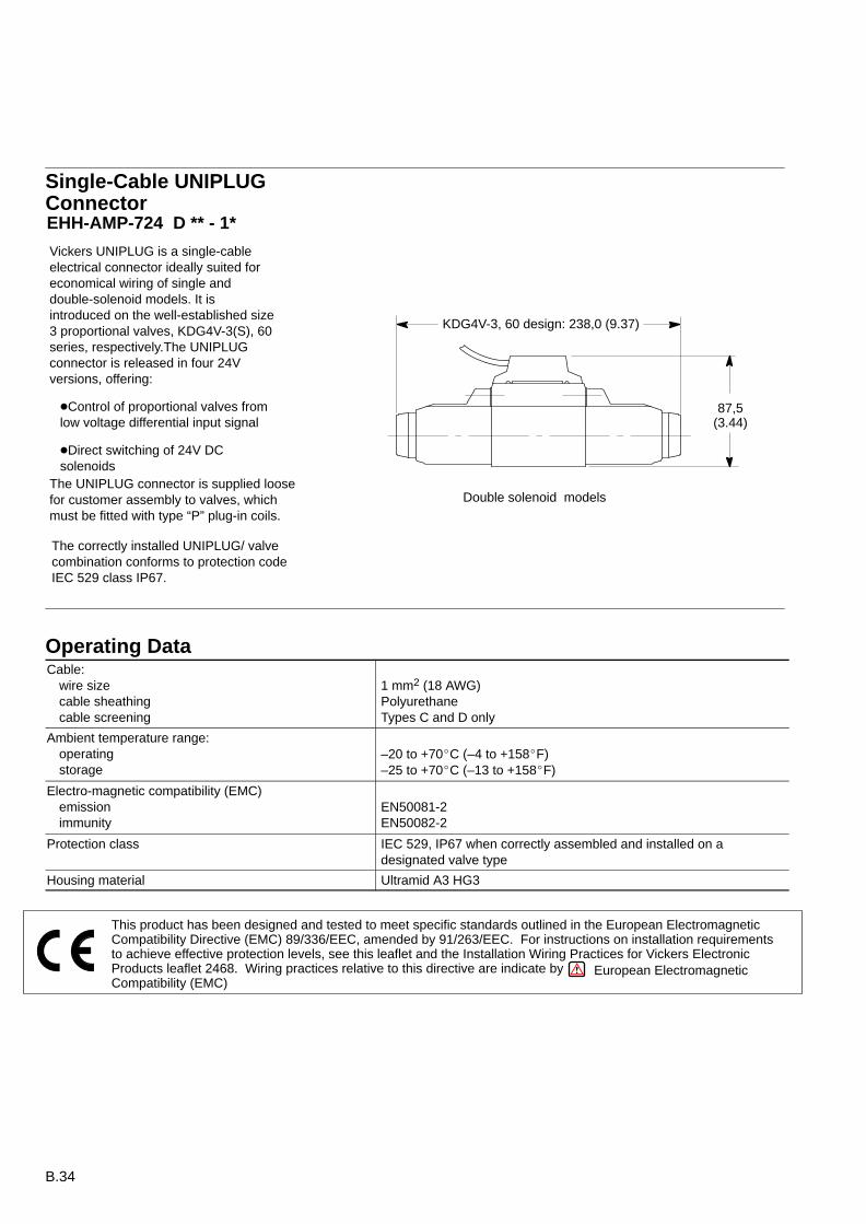
KDG4V-3, 60 design: 238,0 (9.37)
Vickers UNIPLUG is a single-cableelectrical connector ideally suited foreconomical wiring of single anddouble-solenoid models. It isintroduced on the well-established size3 proportional valves, KDG4V-3(S), 60series, respectively.The UNIPLUGconnector is released in four 24Vversions, offering:
Control of proportional valves fromlow voltage differential input signal
Direct switching of 24V DCsolenoids
87,5(3.44)
Double solenoid models
Single-Cable UNIPLUGConnectorEHH-AMP-724 D ** - 1*
The UNIPLUG connector is supplied loosefor customer assembly to valves, whichmust be fitted with type “P” plug-in coils.
The correctly installed UNIPLUG/ valvecombination conforms to protection codeIEC 529 class IP67.
Operating DataCable:
wire sizecable sheathingcable screening
1 mm2 (18 AWG)PolyurethaneTypes C and D only
Ambient temperature range:operatingstorage
–20 to +70C (–4 to +158F)–25 to +70C (–13 to +158F)
Electro-magnetic compatibility (EMC)emissionimmunity
EN50081-2EN50082-2
Protection class IEC 529, IP67 when correctly assembled and installed on adesignated valve type
Housing material Ultramid A3 HG3
This product has been designed and tested to meet specific standards outlined in the European ElectromagneticCompatibility Directive (EMC) 89/336/EEC, amended by 91/263/EEC. For instructions on installation requirementsto achieve effective protection levels, see this leaflet and the Installation Wiring Practices for Vickers ElectronicProducts leaflet 2468. Wiring practices relative to this directive are indicate byCompatibility (EMC)
European Electromagnetic

B.35
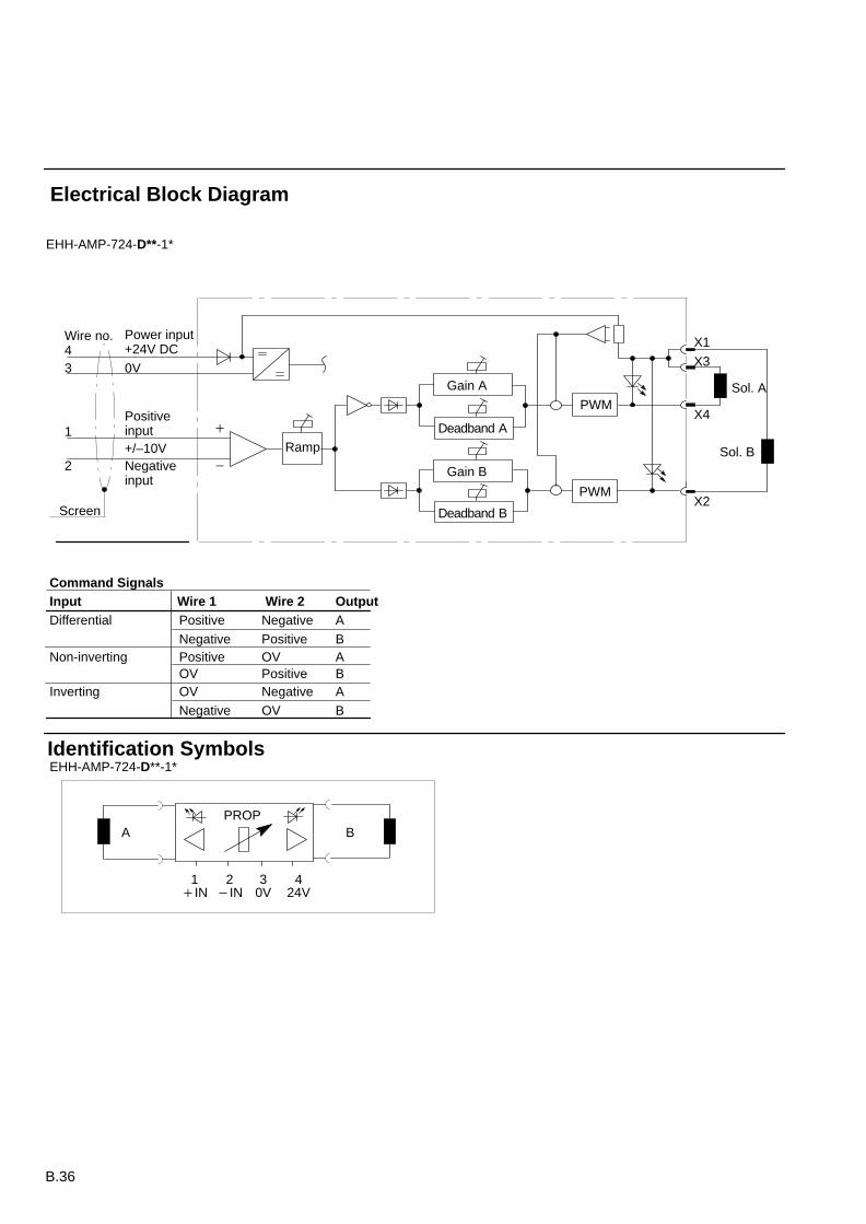
Electrical Data, Type DPlug with proportional amplifiers with independent adjustable gain and deadbandfor each of two solenoid outputs, plus a common adjustable ramp.LEDs show status of output.
Connections (coded to DIN VDE 0293):wire no. 1wire no. 2wire no. 3wire no. 4screen
Positive command signalNegative command signal0V (power and signal)24V power supplyConnect to a suitable ground point
Power supply (to VDE 0160)Max. permissible voltage
24V DC (20.4V to 30.4V incl. 10% ripple)36V DC for less than 100 ms
Protection Reverse polarity protectedShort circuit protected
Differential command signalmax. command-current
Input resistanceProtected against overvoltage
–10V to +10V. See “Command Signal” table on next page1 mA10 k50 volts
Output current per solenoid:ratedmax.
1.6A1.8A
Output voltage at 1.6A output current Typically 1.5V below supply voltage
Max. power consumption with one solenoid energized 35W
Ramp adjustment range 50 ms to 5 sec
Deadband compensation , independent for eachsolenoidTrigger level for deadband
200 to 700 mA+/– 100 mV
Gain adjustment range, independent for eachsolenoid 0.04 to 0.14 A/V
PWM frequency 240 Hz (optimum for KD/TG4V-3(S) valves)
Installation and start-up guidelines GB/D-9144
Vibration can cause potentiometer setting to change by up to approx. 5%. To avoid this effect, it isrecommended to seal the adjusting screws (e.g. Loctite Screwlock 222).
B.36
Inverting
Differential
Identification Symbols
PROP
EHH-AMP-724-D**-1*
A
1IN
30V
424V
2IN
B
1
EHH-AMP-724-D**-1*
Wire no.4
2
Screen
Power input+24V DC
Positiveinput
Negativeinput
0V
X1
X3
X4
X2
Sol. B
Sol. A
3
PWM
Deadband A
Gain A
Ramp
Deadband B
Gain B
PWM
+/–10V
Command SignalsInput Wire 1 Wire 2 Output
Non-inverting
Positive
Negative
Negative
Positive
OV
PositiveOV
Negative
PositiveNegative
OV
OV
BABA
B
A
Electrical Block Diagram
B.37
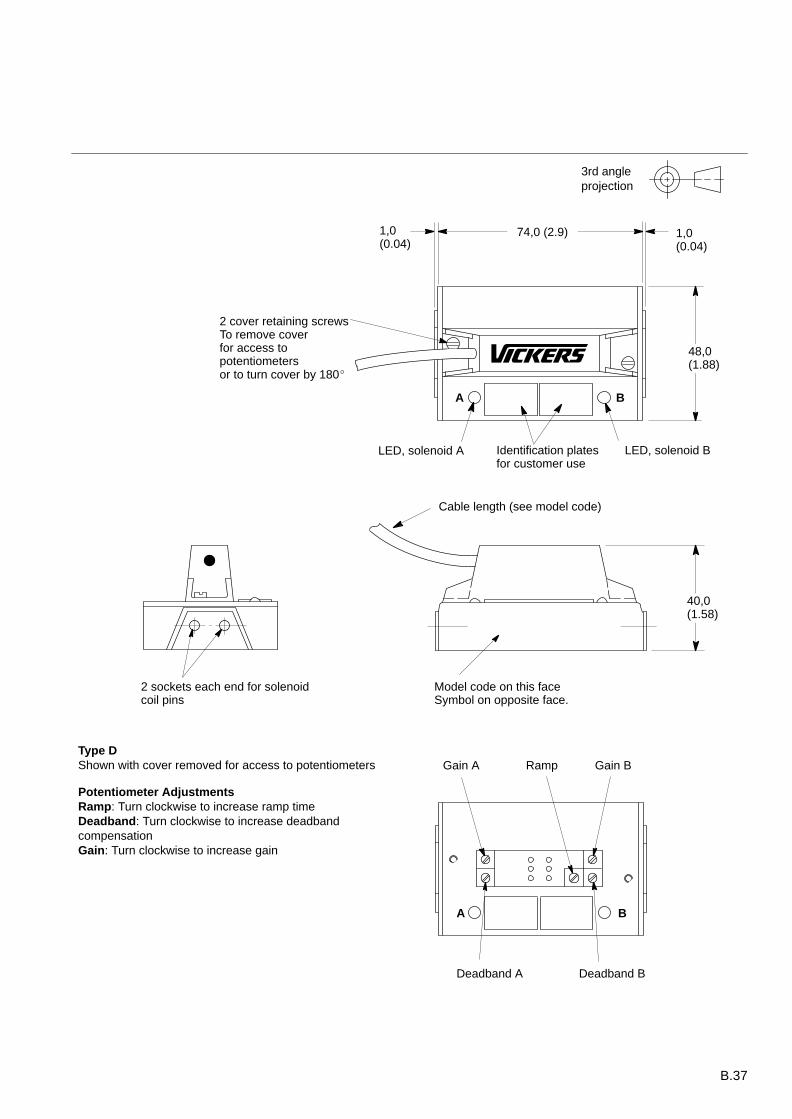
Cable length (see model code)
A B
3rd angleprojection
A B
Type DShown with cover removed for access to potentiometers
Potentiometer AdjustmentsRamp: Turn clockwise to increase ramp timeDeadband: Turn clockwise to increase deadbandcompensationGain: Turn clockwise to increase gain
48,0(1.88)
1,0(0.04)
74,0 (2.9) 1,0(0.04)
2 cover retaining screwsTo remove coverfor access topotentiometersor to turn cover by 180
LED, solenoid A LED, solenoid B
40,0(1.58)
Model code on this faceSymbol on opposite face.
2 sockets each end for solenoidcoil pins
Deadband BDeadband A
Gain BRampGain A
Identification platesfor customer use
B.38
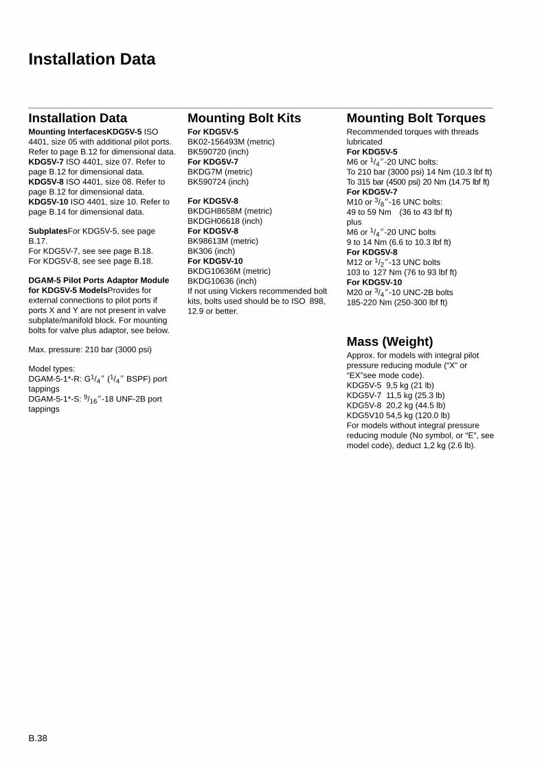
Installation Data
Installation DataMounting InterfacesKDG5V-5 ISO4401, size 05 with additional pilot ports.Refer to page B.12 for dimensional data.KDG5V-7 ISO 4401, size 07. Refer topage B.12 for dimensional data.KDG5V-8 ISO 4401, size 08. Refer topage B.12 for dimensional data.KDG5V-10 ISO 4401, size 10. Refer topage B.14 for dimensional data.
SubplatesFor KDG5V-5, see pageB.17.For KDG5V-7, see see page B.18.For KDG5V-8, see see page B.18.
DGAM-5 Pilot Ports Adaptor Modulefor KDG5V-5 ModelsProvides forexternal connections to pilot ports ifports X and Y are not present in valvesubplate/manifold block. For mountingbolts for valve plus adaptor, see below.
Max. pressure: 210 bar (3000 psi)
Model types:DGAM-5-1*-R: G1/4 (1/4 BSPF) porttappingsDGAM-5-1*-S: 9/16-18 UNF-2B porttappings
Mounting Bolt KitsFor KDG5V-5BK02-156493M (metric)BK590720 (inch)For KDG5V-7BKDG7M (metric)BK590724 (inch)
For KDG5V-8BKDGH8658M (metric)BKDGH06618 (inch)For KDG5V-8BK98613M (metric)BK306 (inch)For KDG5V-10BKDG10636M (metric)BKDG10636 (inch)If not using Vickers recommended boltkits, bolts used should be to ISO 898,12.9 or better.
Mounting Bolt TorquesRecommended torques with threadslubricatedFor KDG5V-5M6 or 1/4-20 UNC bolts:To 210 bar (3000 psi) 14 Nm (10.3 lbf ft)To 315 bar (4500 psi) 20 Nm (14.75 lbf ft)For KDG5V-7M10 or 3/8-16 UNC bolts:49 to 59 Nm (36 to 43 lbf ft)plusM6 or 1/4-20 UNC bolts9 to 14 Nm (6.6 to 10.3 lbf ft)For KDG5V-8M12 or 1/2-13 UNC bolts103 to 127 Nm (76 to 93 lbf ft)For KDG5V-10M20 or 3/4-10 UNC-2B bolts185-220 Nm (250-300 lbf ft)
Mass (Weight)Approx. for models with integral pilotpressure reducing module (“X” or“EX”see mode code).KDG5V-5 9,5 kg (21 lb)KDG5V-7 11,5 kg (25.3 lb)KDG5V-8 20,2 kg (44.5 lb)KDG5V10 54,5 kg (120.0 lb)For models without integral pressurereducing module (No symbol, or “E”, seemodel code), deduct 1,2 kg (2.6 lb).
B.39
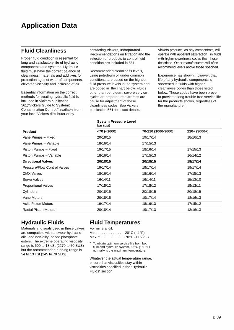
Application Data
Fluid CleanlinessProper fluid condition is essential forlong and satisfactory life of hydrauliccomponents and systems. Hydraulicfluid must have the correct balance ofcleanliness, materials and additives forprotection against wear of components,elevated viscosity and inclusion of air.
Essential information on the correctmethods for treating hydraulic fluid isincluded in Vickers publication561;“Vickers Guide to SystemicContamination Control,” available fromyour local Vickers distributor or by
contacting Vickers, Incorporated.Recommendations on filtration and theselection of products to control fluidcondition are included in 561.
Recommended cleanliness levels,using petroleum oil under commonconditions, are based on the highestfluid pressure levels in the system andare coded in the chart below. Fluidsother than petroleum, severe servicecycles or temperature extremes arecause for adjustment of thesecleanliness codes. See Vickerspublication 561 for exact details.
Vickers products, as any components, willoperate with apparent satisfaction in fluidswith higher cleanliness codes than thosedescribed. Other manufacturers will oftenrecommend levels above those specified.
Experience has shown, however, thatlife of any hydraulic components isshortened in fluids with highercleanliness codes than those listedbelow. These codes have been provento provide a long trouble-free service lifefor the products shown, regardless ofthe manufacturer.
System Pressure Levelbar (psi)
Product <70 (<1000) 70-210 (1000-3000) 210+ (3000+)
Vane Pumps – Fixed 20/18/15 19/17/14 18/16/13
Vane Pumps – Variable 18/16/14 17/15/13
Piston Pumps – Fixed 19/17/15 18/16/14 17/15/13
Piston Pumps – Variable 18/16/14 17/15/13 16/14/12
Directional Valves 20/18/15 20/18/15 19/17/14
Pressure/Flow Control Valves 19/17/14 19/17/14 19/17/14
CMX Valves 18/16/14 18/16/14 17/15/13
Servo Valves 16/14/11 16/14/11 15/13/10
Proportional Valves 17/15/12 17/15/12 15/13/11
Cylinders 20/18/15 20/18/15 20/18/15
Vane Motors 20/18/15 19/17/14 18/16/13
Axial Piston Motors 19/17/14 18/16/13 17/15/12
Radial Piston Motors 20/18/14 19/17/13 18/16/13
Hydraulic FluidsMaterials and seals used in these valvesare compatible with antiwear hydraulicoils, and non-alkyl-based phosphateesters. The extreme operating viscosityrange is 500 to 13 cSt (2270 to 70 SUS)but the recommended running range is54 to 13 cSt (245 to 70 SUS).
Fluid TemperaturesFor mineral oil:Min. –20C (–4F). . . . . . . . . . . . . Max. * +70C (+158F). . . . . . . . . . .
* To obtain optimum service life from bothfluid and hydraulic system, 65C (150F)normally is the maximum temperature.
Whatever the actual temperature range,ensure that viscosities stay withinviscosities specified in the “HydraulicFluids” section.