Embed Size (px)
Citation preview
RE 29188 edition 2016-05 Bosch Rexroth AG
Proportional flow control valve
Features
2-way version Valve with pressure compensator for pressure-
compensated flow control Actuation via proportional solenoid For subplate mounting Porting pattern according to ISO 4401-03-02-0-05 With electrical position control for the metering orifice Axially movable position transducer coil therefore an
easy zero point calibration of the metering orifice is possible without having to interfere with the control electronics (electrical-hydraulic)
Low manufacturing tolerance of the valve and electric amplifier VT-VRPA1-150-1X (analog) and amplifier module VT-MRPA1-150-1X (analog) optional
Flow control in both directions by means of rectifier sandwich plate
Contents
Features 1Ordering code 2 3Symbols 3Function section 4 5Technical data 6 7Characteristic curves 8 9Dimensions 10 11Electrical connections and assignment 11Mating connectors 12Further information 12
Size 6 Component series 2X Maximum operating pressure 210 bar Maximum flow 25 lmin
RE 29188thinspEdition 2016-05Replaces 0207
H6139
Type 2FRE
Inhalt
Features 1Contents 1Ordering code Proportional flow control valve 2Ordering code Rectifier sandwich plate 3Symbols (① = component side ② = plate side) 3Function section 4Function section 5Technical data (For applications outside these values please consult us) 6Technical data (For applications outside these values please consult us) 7Characteristic curves (measured with HLP46 ϑoil = 40 plusmn 5degC) 8Characteristic curves (measured with HLP46 ϑoil = 40 plusmn 5degC) 9Dimensions Proportional flow control valve (dimensions in mm) 10Dimensions Rectifier sandwich plate (dimensions in mm) 11Electrical connections and assignment 11Mating connectors (separate order) 12Further information 12
212 2FRE | Proportional flow control valve
Bosch Rexroth AG RE 29188 edition 2016-05
Ordering code Proportional flow control valve
01 Proportional flow control valve 2-way version 2FRE
02 Size 6 6
03 With external closing of the pressure compensator (suppression of the start-up jump) AWithout external closing of the pressure compensator B
04 Component series 20 hellip 29 (20 hellip 29 unchanged installation and connection dimensions) 2X
Rated flow A rarr B flow characteristic05 ndash Linear
Up to 1 lmin 1LUp to 2 lmin 2LUp to 8 lmin 8Lndash ProgressiveUp to 3 lmin 3QUp to 6 lmin 6QUp to 10 lmin 10QUp to 16 lmin 16QUp to 25 lmin 25Qndash Progressive with rapid traverseFine control range up to 2 lmin 2QE
Electrical connection06 Individual connection
Without mating connector connector DIN EN 175301-803-A (proportional solenoid) and GSA20 (position transducer) K4 1)
07 With check valve RWithout check valve M
Seal material08 FKM seals V
Observe compatibility of seals with hydraulic fluid used (Other seals upon request)
09 Further details in the plain text
01 02 03 04 05 06 07 08 09
2FRE 6 ndash 2X K4 V
1) Mating connectors separate order see page 12 and data sheet 08006 Notice Preferred types and standard units are contained in
the EPS (standard price list)
1
2 TP A B
Proportional flow control valve | 2FRE 312
RE 29188 edition 2016-05 Bosch Rexroth AG
01 Rectifier sandwich plate Z4S
02 Size 6 6
03 Component series 10 hellip 19 (10 hellip 19 unchanged installation and connection dimensions) 1X
Seal material08 FKM seals V
Observe compatibility of seals with hydraulic fluid used (Other seals upon request)
09 Further details in the plain text
01 02 03 04 05
Z4S 6 ndash 1X V
Notice Rectifier sandwich plate impossible with proportional flow control valve version A (with external closing of the pressure compensator)
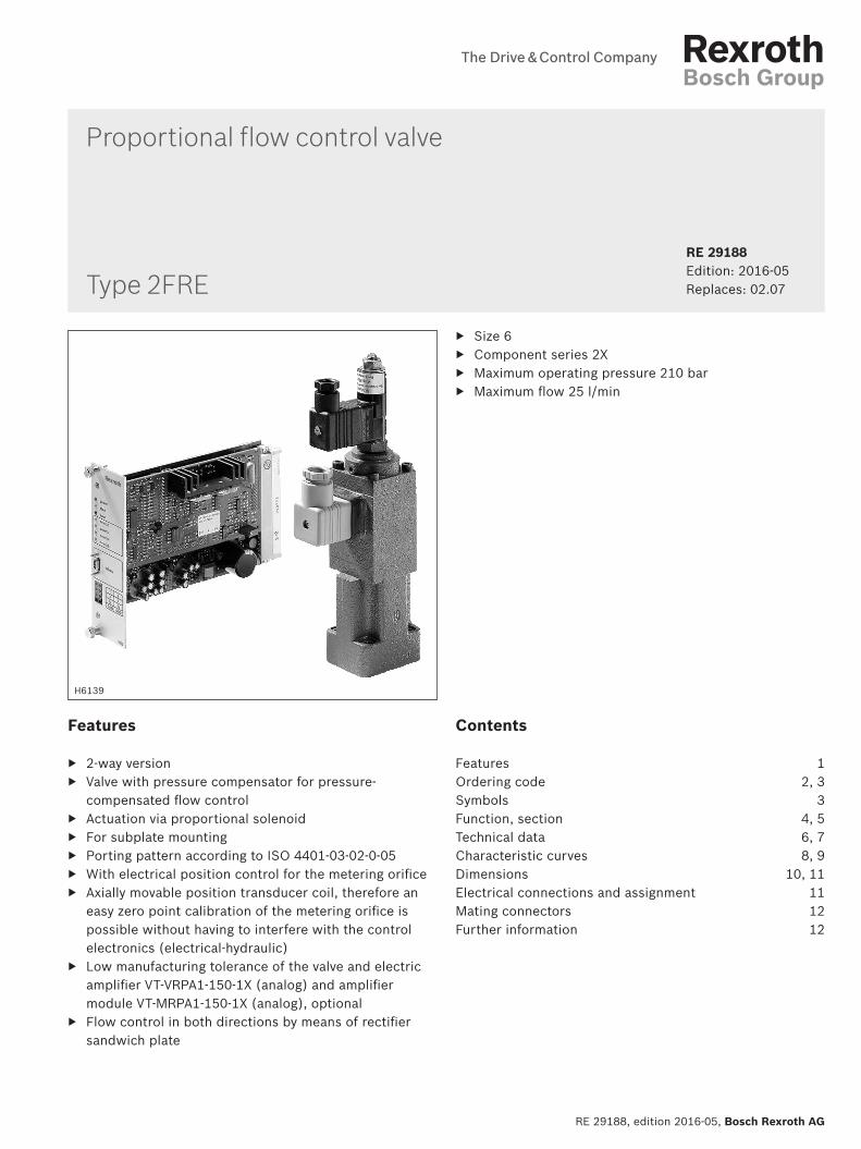
Ordering code Rectifier sandwich plate
Material no R900489356
Rectifier sandwich plate
Proportional flow control valve (simplified detailed) Version BhellipMV Version BRV Version AMV Version ARV
sim
plifi
ed
B
A
B
A
B
A
P
B
A
P
deta
iled
B
A
B
A
B
A P
B
A P
Symbols (① = component side ② = plate side)
A B
2
53
14
412 2FRE | Proportional flow control valve
Bosch Rexroth AG RE 29188 edition 2016-05
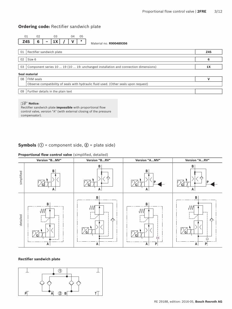
Function section
Proportional flow control valves of the 2FRE type comprise a 2-way function They are capable of controlling a flow indicated by the electrical command value in a pressure- and temperature-compensated mannerThe set-up basically consists of a housing (1) proportional solenoid with inductive position transducer (2) metering orifice (3) pressure compensator (4) as well as check valve (5) optional
Proportional flow control valve version BhellipRV (without external closing with check valve)The flow setting is determined by the indication (0 100) at the command value potentiometer Via the amplifier as well as the proportional solenoid the indicated command value has an effect on the adjustment of the metering orifice (3) The position of the metering orifice (3) is recorded by the inductive position transducer Any existing variations from the command value are corrected by the position controlThe pressure compensator (4) keeps the pressure drop at the metering orifice (3) at a constant value at all times Thus the flow is load-compensated The low temperature drift is the result of the favorable design of the metering orificeWith a command value of 0 the metering orifice is closed In the event of a power failure or cable break at the inductive position transducer the metering orifice closesFrom the command value 0 a smooth start-up is possible Via two ramps in the electric amplifier the metering orifice can be opened and closed with delayVia the check valve (5) a free return flow from B to A is possibleWith an additional rectifier sandwich plate of the Z4S 6 type under the proportional flow control valve the supply and return flow from the actuator can be regulated Type 2FRE 6 B-2XK4RV
Nozzle
2
3
4
7
6
A B P
8
GPBA
P T
BA
Proportional flow control valve | 2FRE 512
RE 29188 edition 2016-05 Bosch Rexroth AG
Function section
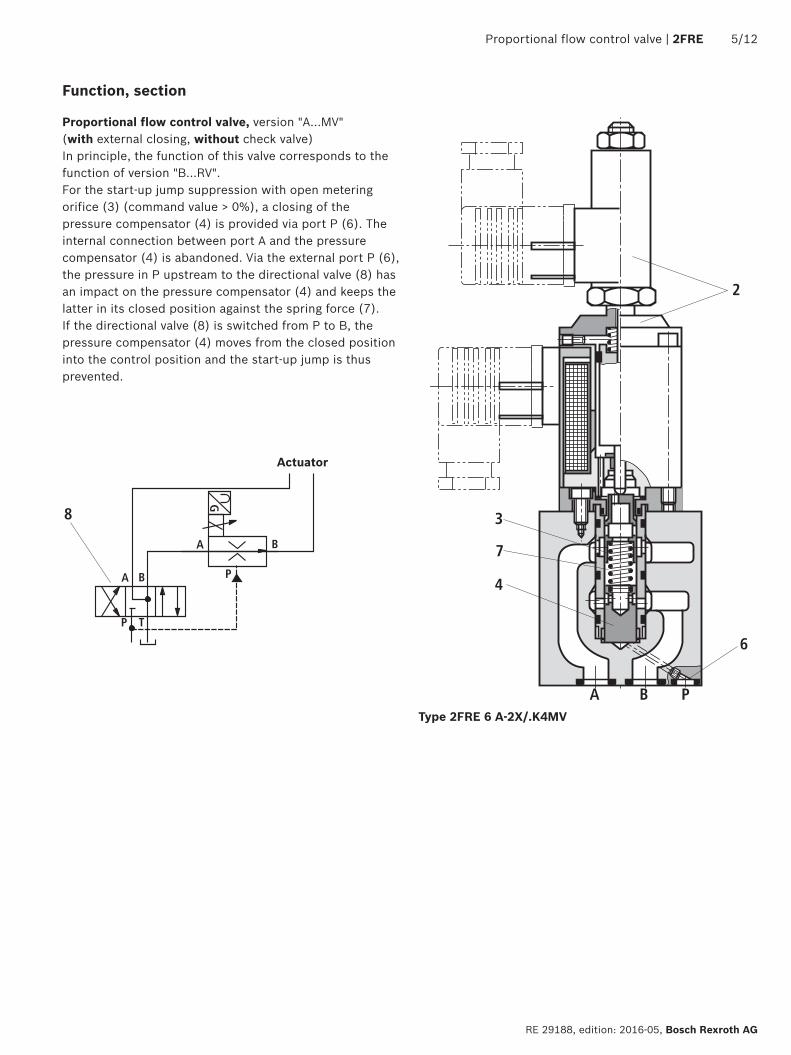
Proportional flow control valve version AhellipMV (with external closing without check valve)In principle the function of this valve corresponds to the function of version BRVFor the start-up jump suppression with open metering orifice (3) (command value gt 0) a closing of the pressure compensator (4) is provided via port P (6) The internal connection between port A and the pressure compensator (4) is abandoned Via the external port P (6) the pressure in P upstream to the directional valve (8) has an impact on the pressure compensator (4) and keeps the latter in its closed position against the spring force (7) If the directional valve (8) is switched from P to B the pressure compensator (4) moves from the closed position into the control position and the start-up jump is thus prevented
Type 2FRE 6 A-2XK4MV
Actuator
612 2FRE | Proportional flow control valve
Bosch Rexroth AG RE 29188 edition 2016-05
Technical data (For applications outside these values please consult us)
generalWeight Proportional flow control valve kg 18
Rectifier sandwich plate kg 09
Installation position Any
Storage temperature range degC ndash20 hellip +80
Ambient temperature range degC ndash20 hellip +50
hydraulic ndash Proportional flow control valve 1)
Maximum operating pressure Port A bar 210
Version 1L 2L 8L 3Q 6Q 10Q 16Q 25Q 2QE
Maximum flow volume lmin 1 2 8 3 6 10 16 25 25
Minimum flow 100 bar cm3min 25 25 50 15 25 50 70 100 15
210 bar cm3min 25 25 50 25 25 50 70 100 25
Maximum leakage flow p A rarr B with a command value
of 0 2)
50 bar cm3min 4 4 6 4 4 6 7 10 4
100 bar cm3min 5 5 8 5 5 8 10 15 5
210 bar cm3min 7 7 12 7 7 12 15 22 7
Minimum pressure differential bar 6 hellip 10
Pressure differential with free return flow B rarr A See characteristic curve page 9
Pressureflow-dependence of inputoutput pressure See characteristic curve page 9
Temperature dependence Temperature drift hydraulic and electric
See characteristic curve page 9
Hydraulic fluid See table page 7
Maximum admissible degree of contamination of the hydraulic fluid Cleanliness class according to ISO 4406 (c)
Class 201815 3)
Hydraulic fluid temperature range degC ndash20 hellip +80
Viscosity range mm2s 15 hellip 380
Hysteresis lt plusmn1 of qVmax
Repetition accuracy lt 1 of qVmax
Manufacturing tolerance
Valve type 2FRE 6 le plusmn3 with command value 33 le plusmn5 with command value 100
Amplifier VT-VRPA1-150 (analog) The amplifier is to be adapted to the valve 4)
Amplifier module VT-MRPA1-150 (analog) The amplifier is to be adapted to the valve 4)
Hydraulic ndash Rectifier sandwich plateMaximum operating pressure bar 210
Cracking pressure bar 07
Rated flow lmin 25
1) Measured with HLP46 and with oil = 40degC plusmn5degC2) Measured with ν = 41 mm2s and = 50degC3) The cleanliness classes stated for the components need to be
maintained in hydraulic systems Effective filtration prevents faults and simultaneously increases the life cycle of the components
Available filters can be found at wwwboschrexrothcomfilter4) Due to tolerances of the oscillator frequency (supply of the
position transducer) amplifiers comprise manufacturing tolerances In new systems or when replacing the amplifier an adaptation of the amplifier setting may be necessary
Proportional flow control valve | 2FRE 712
RE 29188 edition 2016-05 Bosch Rexroth AG
Technical data (For applications outside these values please consult us)
Hydraulic fluid Classification Suitable sealing materials
Standards Data sheet
Mineral oils HL HLP FKM DIN 51524 90220Flame-resistant Water-free HFDU (glycol base) FKM ISO 12922 90222
Important notices on hydraulic fluids For more information and data on the use of other hydraulic fluids please refer to the data sheets above or contact us
There may be limitations regarding the technical valve data (tem-perature pressure range life cycle maintenance intervals etc)
The ignition temperature of the hydraulic fluid used must be 50 K higher than the maximum solenoid surface temperature
electrical ndash Proportional solenoidVoltage type Direct voltageCoil resistance Cold value at 20degC Ω 54
Maximum hot value Ω 82Duty cycle 100Maximum current per solenoid A 15Electrical connection Connector according to DIN EN 175301-803-A 5)
Protection class according to EN 60529 6) IP 65 with mating connector mounted and lockedelectrical ndash Inductive position transducerCoil resistance (total resistance of the coils between PIN) at 20degC (see page 11)
1 and 2 2 and earthing Earthing and 1315 455 315
Electrical connection Connector GSA20 5)
Protection class according to EN 60529 6) IP 65 with mating connector mounted and lockedInductivity mH 6 hellip 8Oscillator frequency kHz 25Electrical position measurement system Differential throttleNominal stroke mm 35
5) Mating connector separate order see page 126) Due to the arising surface temperatures of the solenoid coils the
standards ISO 13732-1 and ISO 4413 are to be observed
Control electronics (separate order)Related amplifier in euro-card format Type VT-VRPA1-150-1X (analog) according to data sheet 30118Related amplifier module Type VT-MRPA1-150-1X (analog) according to data sheet 30221
0 0 100
10
100
20
30
40
50
60
70
80
90
20 40 60 80 100 20 40 60 80
01 20
1
-9
-8
-7
-6
-5
-4
-3
-2
-1
0
05 1 2 10 153 4 5 6 8
-150
0
-15
-30
-60
-75
-135
-120
-105
-90
-45
812 2FRE | Proportional flow control valve
Bosch Rexroth AG RE 29188 edition 2016-05
Characteristic curves (measured with HLP46 ϑoil = 40 plusmn 5degC)
Transition function with stepped command value modification pnom = 100 bar version 25Q
Dependency of the flow from the command value voltage(Flow control of A rarr B) pnom = 50 bar
Time in ms rarr
Frequency in Hz rarr
Frequency response characteristic curves pnom = 100 bar version 25Q
Command value amplitude 45 hellip 55 (50 plusmn5)
Command value amplitude 0 hellip 100 (50 plusmn50)
Pha
se a
ngle
in deg
rarr
Stro
ke in
rarr
Ampl
itude
rat
io in
dB
rarrFl
ow in
lm
in rarr
Command value voltage in rarr
Command value voltage in rarr
Command value voltage in rarr
Flow
in l
min
rarr
Flow
in l
min
rarr
0 24
7
4
1
8 12 16 20
2
3
4
5
6
0 25
6
5
1
10 15 20
2
3
4
5
2600
2400
2500
2300
450
70100
100
8020 30 40 50 60
120
Proportional flow control valve | 2FRE 912
RE 29188 edition 2016-05 Bosch Rexroth AG
Characteristic curves (measured with HLP46 ϑoil = 40 plusmn 5degC)
Pres
sure
diff
eren
tial i
n ba
r rarr
Rectifier sandwich plate
p-qV characteristic curve
Pressure differential via check valve B rarr A orifice closed
Outlet pressure pA(B) in bar rarr (pressure in A 210 bar)
Inlet pressure pnom(A) in bar rarr (pressure in B ~ 0 bar)
Flow
in l
min
rarr
Flow
in l
min
rarr
Flow
in c
m3
min
rarr
Fluid and valve temperature in degC rarr
Flow in lmin rarr
Temperature dependence (version 25Q ndash greatest variation) at p = 30 bar
Flow-dependent pressure
Pres
sure
diff
eren
tial i
n ba
r rarr
Flow in lmin rarr
Proportional flow control valve
Y
32
Oslash126Oslash8
Oslash126Oslash3
10
AB
10
47
63
8
11
PA
F4 F3
BF1 F2
G
4
4
2
1
61
31
5
7
9
8
48
67
114
15
179
15
22
227
45Oslash10
Oslash55
60
A B
P
A B
P
Rzmax 4
001100
1012 2FRE | Proportional flow control valve
Bosch Rexroth AG RE 29188 edition 2016-05
Dimensions Proportional flow control valve (dimensions in mm)
For item explanations valve mounting screws and subplates see page 11
View Y version A
View Y version B
NoticeThe dimensions are nominal dimensions which are subject to tolerances
Required surface quality of the valve contact surface
Rzmax 4
001100
PE
1 2
PE
1 2
B2
A1 B1
1
11
12
62
13
Oslash125 13 Oslash8
A1 B1
40
A1B140
max
35(2
27)
60
Proportional flow control valve | 2FRE 1112
RE 29188 edition 2016-05 Bosch Rexroth AG
1 Valve housing2 Proportional solenoid with inductive position transducer
31 Mating connector for proportional solenoid separate order see page 12
32 Mating connector for position transducer separate order see page 12
4 Space required for removing the mating connector5 Name plate
61 Same seal rings for ports A B P and blind counterbore62 Same seal rings for ports A2 and B2
7 Port A8 Port B9 Blind counterbore Oslash126 mm
10 Machined valve contact surface porting pattern according to ISO 4401-03-02-0-05
11 Rectifier sandwich plate12 Subplate13 Valve contact surface for proportional flow control valve
type 2FRE 6
Subplates (separate order) with porting pattern according to ISO 4401-03-02-0-05 see data sheet 45100
Valve mounting screws (separate order)The following valve mounting screws are recommended
Proportional flow control valve ndash 4 hexagon socket head cap screws ISO 4762 - M5 x 30 - 109-flZn240h-L (friction coefficient 009 hellip 014 according to VDA 235-101) tightening torque MA = 7 Nm plusmn10 material no R913048086
ndash 4 hexagon socket head cap screws ISO 4762 - M5 x 30 - 109 (friction coefficient 008 hellip 016 according to VDI 2230 ndash black) tightening torque MA = 81 Nm plusmn10 material no 2910150205
Rectifier sandwich plate ndash 4 tie rods M5 x 70 material no R901318602
ndash 4 hexagon nuts ISO 4032 - M5 - 10-CM-FE-ZN-5-AN-T0-H-B (friction coefficient 008 hellip 016 according to VDI 2230 ndash black) tightening torque MA = 81 Nm plusmn10 material no R913016628
Notices Rectifier sandwich plate impossible with proportional flow control valve version A (with external closing of the pressure compensator)
The dimensions are nominal dimensions which are subject to tolerances
Dimensions Rectifier sandwich plate (dimensions in mm)
Required surface quality of the valve contact surface
Electrical connections and assignment
Connection at the connector Connection at mating connector
to the amplifier
12
20834
~51286
Oslash18
Oslash45 77
Bosch Rexroth AG RE 29188 edition 2016-05
1212 2FRE | Proportional flow control valve
Bosch Rexroth AG HydraulicsZum Eisengieszliger 197816 Lohr am Main Germany Phone +49 (0) 93 52thinspthinsp18-0 documentationboschrexrothde wwwboschrexrothde
copy This document as well as the data specifications and other information set forth in it are the exclusive property of Bosch Rexroth AG It may not be reproduced or given to third parties without its consentThe data specified above only serve to describe the product No statements concerning a certain condition or suitability for a certain application can be derived from our information The information given does not release the user from the obligation of own judgment and verification It must be remembered that our products are subject to a natural process of wear and aging
Further information
Analog amplifiers Data sheet 30118 Valve amplifier for proportional valves with electrical position feedback Data sheet 30221 Subplates Data sheet 45100 Hydraulic fluids on mineral oil basis Data sheet 90220 Flame-resistant water-free hydraulic fluids Data sheet 90222 Hydraulic valves for industrial applications Operating instructions 07600-B Selection of the filters wwwboschrexrothcomfilter Information on available spare parts wwwboschrexrothcomspc
Mating connectors (separate order)
Mating connector according to DIN EN 175301-803-A material no R901017011 (plastic version) see data sheet 08006
Mating connector GM209N (Pg 9) material no R900013674 (plastic version)
Screening
Seal material NBR

212 2FRE | Proportional flow control valve
Bosch Rexroth AG RE 29188 edition 2016-05
Ordering code Proportional flow control valve
01 Proportional flow control valve 2-way version 2FRE
02 Size 6 6
03 With external closing of the pressure compensator (suppression of the start-up jump) AWithout external closing of the pressure compensator B
04 Component series 20 hellip 29 (20 hellip 29 unchanged installation and connection dimensions) 2X
Rated flow A rarr B flow characteristic05 ndash Linear
Up to 1 lmin 1LUp to 2 lmin 2LUp to 8 lmin 8Lndash ProgressiveUp to 3 lmin 3QUp to 6 lmin 6QUp to 10 lmin 10QUp to 16 lmin 16QUp to 25 lmin 25Qndash Progressive with rapid traverseFine control range up to 2 lmin 2QE
Electrical connection06 Individual connection
Without mating connector connector DIN EN 175301-803-A (proportional solenoid) and GSA20 (position transducer) K4 1)
07 With check valve RWithout check valve M
Seal material08 FKM seals V
Observe compatibility of seals with hydraulic fluid used (Other seals upon request)
09 Further details in the plain text
01 02 03 04 05 06 07 08 09
2FRE 6 ndash 2X K4 V
1) Mating connectors separate order see page 12 and data sheet 08006 Notice Preferred types and standard units are contained in
the EPS (standard price list)
1
2 TP A B
Proportional flow control valve | 2FRE 312
RE 29188 edition 2016-05 Bosch Rexroth AG
01 Rectifier sandwich plate Z4S
02 Size 6 6
03 Component series 10 hellip 19 (10 hellip 19 unchanged installation and connection dimensions) 1X
Seal material08 FKM seals V
Observe compatibility of seals with hydraulic fluid used (Other seals upon request)
09 Further details in the plain text
01 02 03 04 05
Z4S 6 ndash 1X V
Notice Rectifier sandwich plate impossible with proportional flow control valve version A (with external closing of the pressure compensator)
Ordering code Rectifier sandwich plate
Material no R900489356
Rectifier sandwich plate
Proportional flow control valve (simplified detailed) Version BhellipMV Version BRV Version AMV Version ARV
sim
plifi
ed
B
A
B
A
B
A
P
B
A
P
deta
iled
B
A
B
A
B
A P
B
A P
Symbols (① = component side ② = plate side)
A B
2
53
14
412 2FRE | Proportional flow control valve
Bosch Rexroth AG RE 29188 edition 2016-05
Function section
Proportional flow control valves of the 2FRE type comprise a 2-way function They are capable of controlling a flow indicated by the electrical command value in a pressure- and temperature-compensated mannerThe set-up basically consists of a housing (1) proportional solenoid with inductive position transducer (2) metering orifice (3) pressure compensator (4) as well as check valve (5) optional
Proportional flow control valve version BhellipRV (without external closing with check valve)The flow setting is determined by the indication (0 100) at the command value potentiometer Via the amplifier as well as the proportional solenoid the indicated command value has an effect on the adjustment of the metering orifice (3) The position of the metering orifice (3) is recorded by the inductive position transducer Any existing variations from the command value are corrected by the position controlThe pressure compensator (4) keeps the pressure drop at the metering orifice (3) at a constant value at all times Thus the flow is load-compensated The low temperature drift is the result of the favorable design of the metering orificeWith a command value of 0 the metering orifice is closed In the event of a power failure or cable break at the inductive position transducer the metering orifice closesFrom the command value 0 a smooth start-up is possible Via two ramps in the electric amplifier the metering orifice can be opened and closed with delayVia the check valve (5) a free return flow from B to A is possibleWith an additional rectifier sandwich plate of the Z4S 6 type under the proportional flow control valve the supply and return flow from the actuator can be regulated Type 2FRE 6 B-2XK4RV
Nozzle
2
3
4
7
6
A B P
8
GPBA
P T
BA
Proportional flow control valve | 2FRE 512
RE 29188 edition 2016-05 Bosch Rexroth AG
Function section
Proportional flow control valve version AhellipMV (with external closing without check valve)In principle the function of this valve corresponds to the function of version BRVFor the start-up jump suppression with open metering orifice (3) (command value gt 0) a closing of the pressure compensator (4) is provided via port P (6) The internal connection between port A and the pressure compensator (4) is abandoned Via the external port P (6) the pressure in P upstream to the directional valve (8) has an impact on the pressure compensator (4) and keeps the latter in its closed position against the spring force (7) If the directional valve (8) is switched from P to B the pressure compensator (4) moves from the closed position into the control position and the start-up jump is thus prevented
Type 2FRE 6 A-2XK4MV
Actuator
612 2FRE | Proportional flow control valve
Bosch Rexroth AG RE 29188 edition 2016-05
Technical data (For applications outside these values please consult us)
generalWeight Proportional flow control valve kg 18
Rectifier sandwich plate kg 09
Installation position Any
Storage temperature range degC ndash20 hellip +80
Ambient temperature range degC ndash20 hellip +50
hydraulic ndash Proportional flow control valve 1)
Maximum operating pressure Port A bar 210
Version 1L 2L 8L 3Q 6Q 10Q 16Q 25Q 2QE
Maximum flow volume lmin 1 2 8 3 6 10 16 25 25
Minimum flow 100 bar cm3min 25 25 50 15 25 50 70 100 15
210 bar cm3min 25 25 50 25 25 50 70 100 25
Maximum leakage flow p A rarr B with a command value
of 0 2)
50 bar cm3min 4 4 6 4 4 6 7 10 4
100 bar cm3min 5 5 8 5 5 8 10 15 5
210 bar cm3min 7 7 12 7 7 12 15 22 7
Minimum pressure differential bar 6 hellip 10
Pressure differential with free return flow B rarr A See characteristic curve page 9
Pressureflow-dependence of inputoutput pressure See characteristic curve page 9
Temperature dependence Temperature drift hydraulic and electric
See characteristic curve page 9
Hydraulic fluid See table page 7
Maximum admissible degree of contamination of the hydraulic fluid Cleanliness class according to ISO 4406 (c)
Class 201815 3)
Hydraulic fluid temperature range degC ndash20 hellip +80
Viscosity range mm2s 15 hellip 380
Hysteresis lt plusmn1 of qVmax
Repetition accuracy lt 1 of qVmax
Manufacturing tolerance
Valve type 2FRE 6 le plusmn3 with command value 33 le plusmn5 with command value 100
Amplifier VT-VRPA1-150 (analog) The amplifier is to be adapted to the valve 4)
Amplifier module VT-MRPA1-150 (analog) The amplifier is to be adapted to the valve 4)
Hydraulic ndash Rectifier sandwich plateMaximum operating pressure bar 210
Cracking pressure bar 07
Rated flow lmin 25
1) Measured with HLP46 and with oil = 40degC plusmn5degC2) Measured with ν = 41 mm2s and = 50degC3) The cleanliness classes stated for the components need to be
maintained in hydraulic systems Effective filtration prevents faults and simultaneously increases the life cycle of the components
Available filters can be found at wwwboschrexrothcomfilter4) Due to tolerances of the oscillator frequency (supply of the
position transducer) amplifiers comprise manufacturing tolerances In new systems or when replacing the amplifier an adaptation of the amplifier setting may be necessary
Proportional flow control valve | 2FRE 712
RE 29188 edition 2016-05 Bosch Rexroth AG
Technical data (For applications outside these values please consult us)
Hydraulic fluid Classification Suitable sealing materials
Standards Data sheet
Mineral oils HL HLP FKM DIN 51524 90220Flame-resistant Water-free HFDU (glycol base) FKM ISO 12922 90222
Important notices on hydraulic fluids For more information and data on the use of other hydraulic fluids please refer to the data sheets above or contact us
There may be limitations regarding the technical valve data (tem-perature pressure range life cycle maintenance intervals etc)
The ignition temperature of the hydraulic fluid used must be 50 K higher than the maximum solenoid surface temperature
electrical ndash Proportional solenoidVoltage type Direct voltageCoil resistance Cold value at 20degC Ω 54
Maximum hot value Ω 82Duty cycle 100Maximum current per solenoid A 15Electrical connection Connector according to DIN EN 175301-803-A 5)
Protection class according to EN 60529 6) IP 65 with mating connector mounted and lockedelectrical ndash Inductive position transducerCoil resistance (total resistance of the coils between PIN) at 20degC (see page 11)
1 and 2 2 and earthing Earthing and 1315 455 315
Electrical connection Connector GSA20 5)
Protection class according to EN 60529 6) IP 65 with mating connector mounted and lockedInductivity mH 6 hellip 8Oscillator frequency kHz 25Electrical position measurement system Differential throttleNominal stroke mm 35
5) Mating connector separate order see page 126) Due to the arising surface temperatures of the solenoid coils the
standards ISO 13732-1 and ISO 4413 are to be observed
Control electronics (separate order)Related amplifier in euro-card format Type VT-VRPA1-150-1X (analog) according to data sheet 30118Related amplifier module Type VT-MRPA1-150-1X (analog) according to data sheet 30221
0 0 100
10
100
20
30
40
50
60
70
80
90
20 40 60 80 100 20 40 60 80
01 20
1
-9
-8
-7
-6
-5
-4
-3
-2
-1
0
05 1 2 10 153 4 5 6 8
-150
0
-15
-30
-60
-75
-135
-120
-105
-90
-45
812 2FRE | Proportional flow control valve
Bosch Rexroth AG RE 29188 edition 2016-05
Characteristic curves (measured with HLP46 ϑoil = 40 plusmn 5degC)
Transition function with stepped command value modification pnom = 100 bar version 25Q
Dependency of the flow from the command value voltage(Flow control of A rarr B) pnom = 50 bar
Time in ms rarr
Frequency in Hz rarr
Frequency response characteristic curves pnom = 100 bar version 25Q
Command value amplitude 45 hellip 55 (50 plusmn5)
Command value amplitude 0 hellip 100 (50 plusmn50)
Pha
se a
ngle
in deg
rarr
Stro
ke in
rarr
Ampl
itude
rat
io in
dB
rarrFl
ow in
lm
in rarr
Command value voltage in rarr
Command value voltage in rarr
Command value voltage in rarr
Flow
in l
min
rarr
Flow
in l
min
rarr
0 24
7
4
1
8 12 16 20
2
3
4
5
6
0 25
6
5
1
10 15 20
2
3
4
5
2600
2400
2500
2300
450
70100
100
8020 30 40 50 60
120
Proportional flow control valve | 2FRE 912
RE 29188 edition 2016-05 Bosch Rexroth AG
Characteristic curves (measured with HLP46 ϑoil = 40 plusmn 5degC)
Pres
sure
diff
eren
tial i
n ba
r rarr
Rectifier sandwich plate
p-qV characteristic curve
Pressure differential via check valve B rarr A orifice closed
Outlet pressure pA(B) in bar rarr (pressure in A 210 bar)
Inlet pressure pnom(A) in bar rarr (pressure in B ~ 0 bar)
Flow
in l
min
rarr
Flow
in l
min
rarr
Flow
in c
m3
min
rarr
Fluid and valve temperature in degC rarr
Flow in lmin rarr
Temperature dependence (version 25Q ndash greatest variation) at p = 30 bar
Flow-dependent pressure
Pres
sure
diff
eren
tial i
n ba
r rarr
Flow in lmin rarr
Proportional flow control valve
Y
32
Oslash126Oslash8
Oslash126Oslash3
10
AB
10
47
63
8
11
PA
F4 F3
BF1 F2
G
4
4
2
1
61
31
5
7
9
8
48
67
114
15
179
15
22
227
45Oslash10
Oslash55
60
A B
P
A B
P
Rzmax 4
001100
1012 2FRE | Proportional flow control valve
Bosch Rexroth AG RE 29188 edition 2016-05
Dimensions Proportional flow control valve (dimensions in mm)
For item explanations valve mounting screws and subplates see page 11
View Y version A
View Y version B
NoticeThe dimensions are nominal dimensions which are subject to tolerances
Required surface quality of the valve contact surface
Rzmax 4
001100
PE
1 2
PE
1 2
B2
A1 B1
1
11
12
62
13
Oslash125 13 Oslash8
A1 B1
40
A1B140
max
35(2
27)
60
Proportional flow control valve | 2FRE 1112
RE 29188 edition 2016-05 Bosch Rexroth AG
1 Valve housing2 Proportional solenoid with inductive position transducer
31 Mating connector for proportional solenoid separate order see page 12
32 Mating connector for position transducer separate order see page 12
4 Space required for removing the mating connector5 Name plate
61 Same seal rings for ports A B P and blind counterbore62 Same seal rings for ports A2 and B2
7 Port A8 Port B9 Blind counterbore Oslash126 mm
10 Machined valve contact surface porting pattern according to ISO 4401-03-02-0-05
11 Rectifier sandwich plate12 Subplate13 Valve contact surface for proportional flow control valve
type 2FRE 6
Subplates (separate order) with porting pattern according to ISO 4401-03-02-0-05 see data sheet 45100
Valve mounting screws (separate order)The following valve mounting screws are recommended
Proportional flow control valve ndash 4 hexagon socket head cap screws ISO 4762 - M5 x 30 - 109-flZn240h-L (friction coefficient 009 hellip 014 according to VDA 235-101) tightening torque MA = 7 Nm plusmn10 material no R913048086
ndash 4 hexagon socket head cap screws ISO 4762 - M5 x 30 - 109 (friction coefficient 008 hellip 016 according to VDI 2230 ndash black) tightening torque MA = 81 Nm plusmn10 material no 2910150205
Rectifier sandwich plate ndash 4 tie rods M5 x 70 material no R901318602
ndash 4 hexagon nuts ISO 4032 - M5 - 10-CM-FE-ZN-5-AN-T0-H-B (friction coefficient 008 hellip 016 according to VDI 2230 ndash black) tightening torque MA = 81 Nm plusmn10 material no R913016628
Notices Rectifier sandwich plate impossible with proportional flow control valve version A (with external closing of the pressure compensator)
The dimensions are nominal dimensions which are subject to tolerances
Dimensions Rectifier sandwich plate (dimensions in mm)
Required surface quality of the valve contact surface
Electrical connections and assignment
Connection at the connector Connection at mating connector
to the amplifier
12
20834
~51286
Oslash18
Oslash45 77
Bosch Rexroth AG RE 29188 edition 2016-05
1212 2FRE | Proportional flow control valve
Bosch Rexroth AG HydraulicsZum Eisengieszliger 197816 Lohr am Main Germany Phone +49 (0) 93 52thinspthinsp18-0 documentationboschrexrothde wwwboschrexrothde
copy This document as well as the data specifications and other information set forth in it are the exclusive property of Bosch Rexroth AG It may not be reproduced or given to third parties without its consentThe data specified above only serve to describe the product No statements concerning a certain condition or suitability for a certain application can be derived from our information The information given does not release the user from the obligation of own judgment and verification It must be remembered that our products are subject to a natural process of wear and aging
Further information
Analog amplifiers Data sheet 30118 Valve amplifier for proportional valves with electrical position feedback Data sheet 30221 Subplates Data sheet 45100 Hydraulic fluids on mineral oil basis Data sheet 90220 Flame-resistant water-free hydraulic fluids Data sheet 90222 Hydraulic valves for industrial applications Operating instructions 07600-B Selection of the filters wwwboschrexrothcomfilter Information on available spare parts wwwboschrexrothcomspc
Mating connectors (separate order)
Mating connector according to DIN EN 175301-803-A material no R901017011 (plastic version) see data sheet 08006
Mating connector GM209N (Pg 9) material no R900013674 (plastic version)
Screening
Seal material NBR
1
2 TP A B
Proportional flow control valve | 2FRE 312
RE 29188 edition 2016-05 Bosch Rexroth AG
01 Rectifier sandwich plate Z4S
02 Size 6 6
03 Component series 10 hellip 19 (10 hellip 19 unchanged installation and connection dimensions) 1X
Seal material08 FKM seals V
Observe compatibility of seals with hydraulic fluid used (Other seals upon request)
09 Further details in the plain text
01 02 03 04 05
Z4S 6 ndash 1X V
Notice Rectifier sandwich plate impossible with proportional flow control valve version A (with external closing of the pressure compensator)
Ordering code Rectifier sandwich plate
Material no R900489356
Rectifier sandwich plate
Proportional flow control valve (simplified detailed) Version BhellipMV Version BRV Version AMV Version ARV
sim
plifi
ed
B
A
B
A
B
A
P
B
A
P
deta
iled
B
A
B
A
B
A P
B
A P
Symbols (① = component side ② = plate side)
A B
2
53
14
412 2FRE | Proportional flow control valve
Bosch Rexroth AG RE 29188 edition 2016-05
Function section
Proportional flow control valves of the 2FRE type comprise a 2-way function They are capable of controlling a flow indicated by the electrical command value in a pressure- and temperature-compensated mannerThe set-up basically consists of a housing (1) proportional solenoid with inductive position transducer (2) metering orifice (3) pressure compensator (4) as well as check valve (5) optional
Proportional flow control valve version BhellipRV (without external closing with check valve)The flow setting is determined by the indication (0 100) at the command value potentiometer Via the amplifier as well as the proportional solenoid the indicated command value has an effect on the adjustment of the metering orifice (3) The position of the metering orifice (3) is recorded by the inductive position transducer Any existing variations from the command value are corrected by the position controlThe pressure compensator (4) keeps the pressure drop at the metering orifice (3) at a constant value at all times Thus the flow is load-compensated The low temperature drift is the result of the favorable design of the metering orificeWith a command value of 0 the metering orifice is closed In the event of a power failure or cable break at the inductive position transducer the metering orifice closesFrom the command value 0 a smooth start-up is possible Via two ramps in the electric amplifier the metering orifice can be opened and closed with delayVia the check valve (5) a free return flow from B to A is possibleWith an additional rectifier sandwich plate of the Z4S 6 type under the proportional flow control valve the supply and return flow from the actuator can be regulated Type 2FRE 6 B-2XK4RV
Nozzle
2
3
4
7
6
A B P
8
GPBA
P T
BA
Proportional flow control valve | 2FRE 512
RE 29188 edition 2016-05 Bosch Rexroth AG
Function section
Proportional flow control valve version AhellipMV (with external closing without check valve)In principle the function of this valve corresponds to the function of version BRVFor the start-up jump suppression with open metering orifice (3) (command value gt 0) a closing of the pressure compensator (4) is provided via port P (6) The internal connection between port A and the pressure compensator (4) is abandoned Via the external port P (6) the pressure in P upstream to the directional valve (8) has an impact on the pressure compensator (4) and keeps the latter in its closed position against the spring force (7) If the directional valve (8) is switched from P to B the pressure compensator (4) moves from the closed position into the control position and the start-up jump is thus prevented
Type 2FRE 6 A-2XK4MV
Actuator
612 2FRE | Proportional flow control valve
Bosch Rexroth AG RE 29188 edition 2016-05
Technical data (For applications outside these values please consult us)
generalWeight Proportional flow control valve kg 18
Rectifier sandwich plate kg 09
Installation position Any
Storage temperature range degC ndash20 hellip +80
Ambient temperature range degC ndash20 hellip +50
hydraulic ndash Proportional flow control valve 1)
Maximum operating pressure Port A bar 210
Version 1L 2L 8L 3Q 6Q 10Q 16Q 25Q 2QE
Maximum flow volume lmin 1 2 8 3 6 10 16 25 25
Minimum flow 100 bar cm3min 25 25 50 15 25 50 70 100 15
210 bar cm3min 25 25 50 25 25 50 70 100 25
Maximum leakage flow p A rarr B with a command value
of 0 2)
50 bar cm3min 4 4 6 4 4 6 7 10 4
100 bar cm3min 5 5 8 5 5 8 10 15 5
210 bar cm3min 7 7 12 7 7 12 15 22 7
Minimum pressure differential bar 6 hellip 10
Pressure differential with free return flow B rarr A See characteristic curve page 9
Pressureflow-dependence of inputoutput pressure See characteristic curve page 9
Temperature dependence Temperature drift hydraulic and electric
See characteristic curve page 9
Hydraulic fluid See table page 7
Maximum admissible degree of contamination of the hydraulic fluid Cleanliness class according to ISO 4406 (c)
Class 201815 3)
Hydraulic fluid temperature range degC ndash20 hellip +80
Viscosity range mm2s 15 hellip 380
Hysteresis lt plusmn1 of qVmax
Repetition accuracy lt 1 of qVmax
Manufacturing tolerance
Valve type 2FRE 6 le plusmn3 with command value 33 le plusmn5 with command value 100
Amplifier VT-VRPA1-150 (analog) The amplifier is to be adapted to the valve 4)
Amplifier module VT-MRPA1-150 (analog) The amplifier is to be adapted to the valve 4)
Hydraulic ndash Rectifier sandwich plateMaximum operating pressure bar 210
Cracking pressure bar 07
Rated flow lmin 25
1) Measured with HLP46 and with oil = 40degC plusmn5degC2) Measured with ν = 41 mm2s and = 50degC3) The cleanliness classes stated for the components need to be
maintained in hydraulic systems Effective filtration prevents faults and simultaneously increases the life cycle of the components
Available filters can be found at wwwboschrexrothcomfilter4) Due to tolerances of the oscillator frequency (supply of the
position transducer) amplifiers comprise manufacturing tolerances In new systems or when replacing the amplifier an adaptation of the amplifier setting may be necessary
Proportional flow control valve | 2FRE 712
RE 29188 edition 2016-05 Bosch Rexroth AG
Technical data (For applications outside these values please consult us)
Hydraulic fluid Classification Suitable sealing materials
Standards Data sheet
Mineral oils HL HLP FKM DIN 51524 90220Flame-resistant Water-free HFDU (glycol base) FKM ISO 12922 90222
Important notices on hydraulic fluids For more information and data on the use of other hydraulic fluids please refer to the data sheets above or contact us
There may be limitations regarding the technical valve data (tem-perature pressure range life cycle maintenance intervals etc)
The ignition temperature of the hydraulic fluid used must be 50 K higher than the maximum solenoid surface temperature
electrical ndash Proportional solenoidVoltage type Direct voltageCoil resistance Cold value at 20degC Ω 54
Maximum hot value Ω 82Duty cycle 100Maximum current per solenoid A 15Electrical connection Connector according to DIN EN 175301-803-A 5)
Protection class according to EN 60529 6) IP 65 with mating connector mounted and lockedelectrical ndash Inductive position transducerCoil resistance (total resistance of the coils between PIN) at 20degC (see page 11)
1 and 2 2 and earthing Earthing and 1315 455 315
Electrical connection Connector GSA20 5)
Protection class according to EN 60529 6) IP 65 with mating connector mounted and lockedInductivity mH 6 hellip 8Oscillator frequency kHz 25Electrical position measurement system Differential throttleNominal stroke mm 35
5) Mating connector separate order see page 126) Due to the arising surface temperatures of the solenoid coils the
standards ISO 13732-1 and ISO 4413 are to be observed
Control electronics (separate order)Related amplifier in euro-card format Type VT-VRPA1-150-1X (analog) according to data sheet 30118Related amplifier module Type VT-MRPA1-150-1X (analog) according to data sheet 30221
0 0 100
10
100
20
30
40
50
60
70
80
90
20 40 60 80 100 20 40 60 80
01 20
1
-9
-8
-7
-6
-5
-4
-3
-2
-1
0
05 1 2 10 153 4 5 6 8
-150
0
-15
-30
-60
-75
-135
-120
-105
-90
-45
812 2FRE | Proportional flow control valve
Bosch Rexroth AG RE 29188 edition 2016-05
Characteristic curves (measured with HLP46 ϑoil = 40 plusmn 5degC)
Transition function with stepped command value modification pnom = 100 bar version 25Q
Dependency of the flow from the command value voltage(Flow control of A rarr B) pnom = 50 bar
Time in ms rarr
Frequency in Hz rarr
Frequency response characteristic curves pnom = 100 bar version 25Q
Command value amplitude 45 hellip 55 (50 plusmn5)
Command value amplitude 0 hellip 100 (50 plusmn50)
Pha
se a
ngle
in deg
rarr
Stro
ke in
rarr
Ampl
itude
rat
io in
dB
rarrFl
ow in
lm
in rarr
Command value voltage in rarr
Command value voltage in rarr
Command value voltage in rarr
Flow
in l
min
rarr
Flow
in l
min
rarr
0 24
7
4
1
8 12 16 20
2
3
4
5
6
0 25
6
5
1
10 15 20
2
3
4
5
2600
2400
2500
2300
450
70100
100
8020 30 40 50 60
120
Proportional flow control valve | 2FRE 912
RE 29188 edition 2016-05 Bosch Rexroth AG
Characteristic curves (measured with HLP46 ϑoil = 40 plusmn 5degC)
Pres
sure
diff
eren
tial i
n ba
r rarr
Rectifier sandwich plate
p-qV characteristic curve
Pressure differential via check valve B rarr A orifice closed
Outlet pressure pA(B) in bar rarr (pressure in A 210 bar)
Inlet pressure pnom(A) in bar rarr (pressure in B ~ 0 bar)
Flow
in l
min
rarr
Flow
in l
min
rarr
Flow
in c
m3
min
rarr
Fluid and valve temperature in degC rarr
Flow in lmin rarr
Temperature dependence (version 25Q ndash greatest variation) at p = 30 bar
Flow-dependent pressure
Pres
sure
diff
eren
tial i
n ba
r rarr
Flow in lmin rarr
Proportional flow control valve
Y
32
Oslash126Oslash8
Oslash126Oslash3
10
AB
10
47
63
8
11
PA
F4 F3
BF1 F2
G
4
4
2
1
61
31
5
7
9
8
48
67
114
15
179
15
22
227
45Oslash10
Oslash55
60
A B
P
A B
P
Rzmax 4
001100
1012 2FRE | Proportional flow control valve
Bosch Rexroth AG RE 29188 edition 2016-05
Dimensions Proportional flow control valve (dimensions in mm)
For item explanations valve mounting screws and subplates see page 11
View Y version A
View Y version B
NoticeThe dimensions are nominal dimensions which are subject to tolerances
Required surface quality of the valve contact surface
Rzmax 4
001100
PE
1 2
PE
1 2
B2
A1 B1
1
11
12
62
13
Oslash125 13 Oslash8
A1 B1
40
A1B140
max
35(2
27)
60
Proportional flow control valve | 2FRE 1112
RE 29188 edition 2016-05 Bosch Rexroth AG
1 Valve housing2 Proportional solenoid with inductive position transducer
31 Mating connector for proportional solenoid separate order see page 12
32 Mating connector for position transducer separate order see page 12
4 Space required for removing the mating connector5 Name plate
61 Same seal rings for ports A B P and blind counterbore62 Same seal rings for ports A2 and B2
7 Port A8 Port B9 Blind counterbore Oslash126 mm
10 Machined valve contact surface porting pattern according to ISO 4401-03-02-0-05
11 Rectifier sandwich plate12 Subplate13 Valve contact surface for proportional flow control valve
type 2FRE 6
Subplates (separate order) with porting pattern according to ISO 4401-03-02-0-05 see data sheet 45100
Valve mounting screws (separate order)The following valve mounting screws are recommended
Proportional flow control valve ndash 4 hexagon socket head cap screws ISO 4762 - M5 x 30 - 109-flZn240h-L (friction coefficient 009 hellip 014 according to VDA 235-101) tightening torque MA = 7 Nm plusmn10 material no R913048086
ndash 4 hexagon socket head cap screws ISO 4762 - M5 x 30 - 109 (friction coefficient 008 hellip 016 according to VDI 2230 ndash black) tightening torque MA = 81 Nm plusmn10 material no 2910150205
Rectifier sandwich plate ndash 4 tie rods M5 x 70 material no R901318602
ndash 4 hexagon nuts ISO 4032 - M5 - 10-CM-FE-ZN-5-AN-T0-H-B (friction coefficient 008 hellip 016 according to VDI 2230 ndash black) tightening torque MA = 81 Nm plusmn10 material no R913016628
Notices Rectifier sandwich plate impossible with proportional flow control valve version A (with external closing of the pressure compensator)
The dimensions are nominal dimensions which are subject to tolerances
Dimensions Rectifier sandwich plate (dimensions in mm)
Required surface quality of the valve contact surface
Electrical connections and assignment
Connection at the connector Connection at mating connector
to the amplifier
12
20834
~51286
Oslash18
Oslash45 77
Bosch Rexroth AG RE 29188 edition 2016-05
1212 2FRE | Proportional flow control valve
Bosch Rexroth AG HydraulicsZum Eisengieszliger 197816 Lohr am Main Germany Phone +49 (0) 93 52thinspthinsp18-0 documentationboschrexrothde wwwboschrexrothde
copy This document as well as the data specifications and other information set forth in it are the exclusive property of Bosch Rexroth AG It may not be reproduced or given to third parties without its consentThe data specified above only serve to describe the product No statements concerning a certain condition or suitability for a certain application can be derived from our information The information given does not release the user from the obligation of own judgment and verification It must be remembered that our products are subject to a natural process of wear and aging
Further information
Analog amplifiers Data sheet 30118 Valve amplifier for proportional valves with electrical position feedback Data sheet 30221 Subplates Data sheet 45100 Hydraulic fluids on mineral oil basis Data sheet 90220 Flame-resistant water-free hydraulic fluids Data sheet 90222 Hydraulic valves for industrial applications Operating instructions 07600-B Selection of the filters wwwboschrexrothcomfilter Information on available spare parts wwwboschrexrothcomspc
Mating connectors (separate order)
Mating connector according to DIN EN 175301-803-A material no R901017011 (plastic version) see data sheet 08006
Mating connector GM209N (Pg 9) material no R900013674 (plastic version)
Screening
Seal material NBR
A B
2
53
14
412 2FRE | Proportional flow control valve
Bosch Rexroth AG RE 29188 edition 2016-05
Function section
Proportional flow control valves of the 2FRE type comprise a 2-way function They are capable of controlling a flow indicated by the electrical command value in a pressure- and temperature-compensated mannerThe set-up basically consists of a housing (1) proportional solenoid with inductive position transducer (2) metering orifice (3) pressure compensator (4) as well as check valve (5) optional
Proportional flow control valve version BhellipRV (without external closing with check valve)The flow setting is determined by the indication (0 100) at the command value potentiometer Via the amplifier as well as the proportional solenoid the indicated command value has an effect on the adjustment of the metering orifice (3) The position of the metering orifice (3) is recorded by the inductive position transducer Any existing variations from the command value are corrected by the position controlThe pressure compensator (4) keeps the pressure drop at the metering orifice (3) at a constant value at all times Thus the flow is load-compensated The low temperature drift is the result of the favorable design of the metering orificeWith a command value of 0 the metering orifice is closed In the event of a power failure or cable break at the inductive position transducer the metering orifice closesFrom the command value 0 a smooth start-up is possible Via two ramps in the electric amplifier the metering orifice can be opened and closed with delayVia the check valve (5) a free return flow from B to A is possibleWith an additional rectifier sandwich plate of the Z4S 6 type under the proportional flow control valve the supply and return flow from the actuator can be regulated Type 2FRE 6 B-2XK4RV
Nozzle
2
3
4
7
6
A B P
8
GPBA
P T
BA
Proportional flow control valve | 2FRE 512
RE 29188 edition 2016-05 Bosch Rexroth AG
Function section
Proportional flow control valve version AhellipMV (with external closing without check valve)In principle the function of this valve corresponds to the function of version BRVFor the start-up jump suppression with open metering orifice (3) (command value gt 0) a closing of the pressure compensator (4) is provided via port P (6) The internal connection between port A and the pressure compensator (4) is abandoned Via the external port P (6) the pressure in P upstream to the directional valve (8) has an impact on the pressure compensator (4) and keeps the latter in its closed position against the spring force (7) If the directional valve (8) is switched from P to B the pressure compensator (4) moves from the closed position into the control position and the start-up jump is thus prevented
Type 2FRE 6 A-2XK4MV
Actuator
612 2FRE | Proportional flow control valve
Bosch Rexroth AG RE 29188 edition 2016-05
Technical data (For applications outside these values please consult us)
generalWeight Proportional flow control valve kg 18
Rectifier sandwich plate kg 09
Installation position Any
Storage temperature range degC ndash20 hellip +80
Ambient temperature range degC ndash20 hellip +50
hydraulic ndash Proportional flow control valve 1)
Maximum operating pressure Port A bar 210
Version 1L 2L 8L 3Q 6Q 10Q 16Q 25Q 2QE
Maximum flow volume lmin 1 2 8 3 6 10 16 25 25
Minimum flow 100 bar cm3min 25 25 50 15 25 50 70 100 15
210 bar cm3min 25 25 50 25 25 50 70 100 25
Maximum leakage flow p A rarr B with a command value
of 0 2)
50 bar cm3min 4 4 6 4 4 6 7 10 4
100 bar cm3min 5 5 8 5 5 8 10 15 5
210 bar cm3min 7 7 12 7 7 12 15 22 7
Minimum pressure differential bar 6 hellip 10
Pressure differential with free return flow B rarr A See characteristic curve page 9
Pressureflow-dependence of inputoutput pressure See characteristic curve page 9
Temperature dependence Temperature drift hydraulic and electric
See characteristic curve page 9
Hydraulic fluid See table page 7
Maximum admissible degree of contamination of the hydraulic fluid Cleanliness class according to ISO 4406 (c)
Class 201815 3)
Hydraulic fluid temperature range degC ndash20 hellip +80
Viscosity range mm2s 15 hellip 380
Hysteresis lt plusmn1 of qVmax
Repetition accuracy lt 1 of qVmax
Manufacturing tolerance
Valve type 2FRE 6 le plusmn3 with command value 33 le plusmn5 with command value 100
Amplifier VT-VRPA1-150 (analog) The amplifier is to be adapted to the valve 4)
Amplifier module VT-MRPA1-150 (analog) The amplifier is to be adapted to the valve 4)
Hydraulic ndash Rectifier sandwich plateMaximum operating pressure bar 210
Cracking pressure bar 07
Rated flow lmin 25
1) Measured with HLP46 and with oil = 40degC plusmn5degC2) Measured with ν = 41 mm2s and = 50degC3) The cleanliness classes stated for the components need to be
maintained in hydraulic systems Effective filtration prevents faults and simultaneously increases the life cycle of the components
Available filters can be found at wwwboschrexrothcomfilter4) Due to tolerances of the oscillator frequency (supply of the
position transducer) amplifiers comprise manufacturing tolerances In new systems or when replacing the amplifier an adaptation of the amplifier setting may be necessary
Proportional flow control valve | 2FRE 712
RE 29188 edition 2016-05 Bosch Rexroth AG
Technical data (For applications outside these values please consult us)
Hydraulic fluid Classification Suitable sealing materials
Standards Data sheet
Mineral oils HL HLP FKM DIN 51524 90220Flame-resistant Water-free HFDU (glycol base) FKM ISO 12922 90222
Important notices on hydraulic fluids For more information and data on the use of other hydraulic fluids please refer to the data sheets above or contact us
There may be limitations regarding the technical valve data (tem-perature pressure range life cycle maintenance intervals etc)
The ignition temperature of the hydraulic fluid used must be 50 K higher than the maximum solenoid surface temperature
electrical ndash Proportional solenoidVoltage type Direct voltageCoil resistance Cold value at 20degC Ω 54
Maximum hot value Ω 82Duty cycle 100Maximum current per solenoid A 15Electrical connection Connector according to DIN EN 175301-803-A 5)
Protection class according to EN 60529 6) IP 65 with mating connector mounted and lockedelectrical ndash Inductive position transducerCoil resistance (total resistance of the coils between PIN) at 20degC (see page 11)
1 and 2 2 and earthing Earthing and 1315 455 315
Electrical connection Connector GSA20 5)
Protection class according to EN 60529 6) IP 65 with mating connector mounted and lockedInductivity mH 6 hellip 8Oscillator frequency kHz 25Electrical position measurement system Differential throttleNominal stroke mm 35
5) Mating connector separate order see page 126) Due to the arising surface temperatures of the solenoid coils the
standards ISO 13732-1 and ISO 4413 are to be observed
Control electronics (separate order)Related amplifier in euro-card format Type VT-VRPA1-150-1X (analog) according to data sheet 30118Related amplifier module Type VT-MRPA1-150-1X (analog) according to data sheet 30221
0 0 100
10
100
20
30
40
50
60
70
80
90
20 40 60 80 100 20 40 60 80
01 20
1
-9
-8
-7
-6
-5
-4
-3
-2
-1
0
05 1 2 10 153 4 5 6 8
-150
0
-15
-30
-60
-75
-135
-120
-105
-90
-45
812 2FRE | Proportional flow control valve
Bosch Rexroth AG RE 29188 edition 2016-05
Characteristic curves (measured with HLP46 ϑoil = 40 plusmn 5degC)
Transition function with stepped command value modification pnom = 100 bar version 25Q
Dependency of the flow from the command value voltage(Flow control of A rarr B) pnom = 50 bar
Time in ms rarr
Frequency in Hz rarr
Frequency response characteristic curves pnom = 100 bar version 25Q
Command value amplitude 45 hellip 55 (50 plusmn5)
Command value amplitude 0 hellip 100 (50 plusmn50)
Pha
se a
ngle
in deg
rarr
Stro
ke in
rarr
Ampl
itude
rat
io in
dB
rarrFl
ow in
lm
in rarr
Command value voltage in rarr
Command value voltage in rarr
Command value voltage in rarr
Flow
in l
min
rarr
Flow
in l
min
rarr
0 24
7
4
1
8 12 16 20
2
3
4
5
6
0 25
6
5
1
10 15 20
2
3
4
5
2600
2400
2500
2300
450
70100
100
8020 30 40 50 60
120
Proportional flow control valve | 2FRE 912
RE 29188 edition 2016-05 Bosch Rexroth AG
Characteristic curves (measured with HLP46 ϑoil = 40 plusmn 5degC)
Pres
sure
diff
eren
tial i
n ba
r rarr
Rectifier sandwich plate
p-qV characteristic curve
Pressure differential via check valve B rarr A orifice closed
Outlet pressure pA(B) in bar rarr (pressure in A 210 bar)
Inlet pressure pnom(A) in bar rarr (pressure in B ~ 0 bar)
Flow
in l
min
rarr
Flow
in l
min
rarr
Flow
in c
m3
min
rarr
Fluid and valve temperature in degC rarr
Flow in lmin rarr
Temperature dependence (version 25Q ndash greatest variation) at p = 30 bar
Flow-dependent pressure
Pres
sure
diff
eren
tial i
n ba
r rarr
Flow in lmin rarr
Proportional flow control valve
Y
32
Oslash126Oslash8
Oslash126Oslash3
10
AB
10
47
63
8
11
PA
F4 F3
BF1 F2
G
4
4
2
1
61
31
5
7
9
8
48
67
114
15
179
15
22
227
45Oslash10
Oslash55
60
A B
P
A B
P
Rzmax 4
001100
1012 2FRE | Proportional flow control valve
Bosch Rexroth AG RE 29188 edition 2016-05
Dimensions Proportional flow control valve (dimensions in mm)
For item explanations valve mounting screws and subplates see page 11
View Y version A
View Y version B
NoticeThe dimensions are nominal dimensions which are subject to tolerances
Required surface quality of the valve contact surface
Rzmax 4
001100
PE
1 2
PE
1 2
B2
A1 B1
1
11
12
62
13
Oslash125 13 Oslash8
A1 B1
40
A1B140
max
35(2
27)
60
Proportional flow control valve | 2FRE 1112
RE 29188 edition 2016-05 Bosch Rexroth AG
1 Valve housing2 Proportional solenoid with inductive position transducer
31 Mating connector for proportional solenoid separate order see page 12
32 Mating connector for position transducer separate order see page 12
4 Space required for removing the mating connector5 Name plate
61 Same seal rings for ports A B P and blind counterbore62 Same seal rings for ports A2 and B2
7 Port A8 Port B9 Blind counterbore Oslash126 mm
10 Machined valve contact surface porting pattern according to ISO 4401-03-02-0-05
11 Rectifier sandwich plate12 Subplate13 Valve contact surface for proportional flow control valve
type 2FRE 6
Subplates (separate order) with porting pattern according to ISO 4401-03-02-0-05 see data sheet 45100
Valve mounting screws (separate order)The following valve mounting screws are recommended
Proportional flow control valve ndash 4 hexagon socket head cap screws ISO 4762 - M5 x 30 - 109-flZn240h-L (friction coefficient 009 hellip 014 according to VDA 235-101) tightening torque MA = 7 Nm plusmn10 material no R913048086
ndash 4 hexagon socket head cap screws ISO 4762 - M5 x 30 - 109 (friction coefficient 008 hellip 016 according to VDI 2230 ndash black) tightening torque MA = 81 Nm plusmn10 material no 2910150205
Rectifier sandwich plate ndash 4 tie rods M5 x 70 material no R901318602
ndash 4 hexagon nuts ISO 4032 - M5 - 10-CM-FE-ZN-5-AN-T0-H-B (friction coefficient 008 hellip 016 according to VDI 2230 ndash black) tightening torque MA = 81 Nm plusmn10 material no R913016628
Notices Rectifier sandwich plate impossible with proportional flow control valve version A (with external closing of the pressure compensator)
The dimensions are nominal dimensions which are subject to tolerances
Dimensions Rectifier sandwich plate (dimensions in mm)
Required surface quality of the valve contact surface
Electrical connections and assignment
Connection at the connector Connection at mating connector
to the amplifier
12
20834
~51286
Oslash18
Oslash45 77
Bosch Rexroth AG RE 29188 edition 2016-05
1212 2FRE | Proportional flow control valve
Bosch Rexroth AG HydraulicsZum Eisengieszliger 197816 Lohr am Main Germany Phone +49 (0) 93 52thinspthinsp18-0 documentationboschrexrothde wwwboschrexrothde
copy This document as well as the data specifications and other information set forth in it are the exclusive property of Bosch Rexroth AG It may not be reproduced or given to third parties without its consentThe data specified above only serve to describe the product No statements concerning a certain condition or suitability for a certain application can be derived from our information The information given does not release the user from the obligation of own judgment and verification It must be remembered that our products are subject to a natural process of wear and aging
Further information
Analog amplifiers Data sheet 30118 Valve amplifier for proportional valves with electrical position feedback Data sheet 30221 Subplates Data sheet 45100 Hydraulic fluids on mineral oil basis Data sheet 90220 Flame-resistant water-free hydraulic fluids Data sheet 90222 Hydraulic valves for industrial applications Operating instructions 07600-B Selection of the filters wwwboschrexrothcomfilter Information on available spare parts wwwboschrexrothcomspc
Mating connectors (separate order)
Mating connector according to DIN EN 175301-803-A material no R901017011 (plastic version) see data sheet 08006
Mating connector GM209N (Pg 9) material no R900013674 (plastic version)
Screening
Seal material NBR
2
3
4
7
6
A B P
8
GPBA
P T
BA
Proportional flow control valve | 2FRE 512
RE 29188 edition 2016-05 Bosch Rexroth AG
Function section
Proportional flow control valve version AhellipMV (with external closing without check valve)In principle the function of this valve corresponds to the function of version BRVFor the start-up jump suppression with open metering orifice (3) (command value gt 0) a closing of the pressure compensator (4) is provided via port P (6) The internal connection between port A and the pressure compensator (4) is abandoned Via the external port P (6) the pressure in P upstream to the directional valve (8) has an impact on the pressure compensator (4) and keeps the latter in its closed position against the spring force (7) If the directional valve (8) is switched from P to B the pressure compensator (4) moves from the closed position into the control position and the start-up jump is thus prevented
Type 2FRE 6 A-2XK4MV
Actuator
612 2FRE | Proportional flow control valve
Bosch Rexroth AG RE 29188 edition 2016-05
Technical data (For applications outside these values please consult us)
generalWeight Proportional flow control valve kg 18
Rectifier sandwich plate kg 09
Installation position Any
Storage temperature range degC ndash20 hellip +80
Ambient temperature range degC ndash20 hellip +50
hydraulic ndash Proportional flow control valve 1)
Maximum operating pressure Port A bar 210
Version 1L 2L 8L 3Q 6Q 10Q 16Q 25Q 2QE
Maximum flow volume lmin 1 2 8 3 6 10 16 25 25
Minimum flow 100 bar cm3min 25 25 50 15 25 50 70 100 15
210 bar cm3min 25 25 50 25 25 50 70 100 25
Maximum leakage flow p A rarr B with a command value
of 0 2)
50 bar cm3min 4 4 6 4 4 6 7 10 4
100 bar cm3min 5 5 8 5 5 8 10 15 5
210 bar cm3min 7 7 12 7 7 12 15 22 7
Minimum pressure differential bar 6 hellip 10
Pressure differential with free return flow B rarr A See characteristic curve page 9
Pressureflow-dependence of inputoutput pressure See characteristic curve page 9
Temperature dependence Temperature drift hydraulic and electric
See characteristic curve page 9
Hydraulic fluid See table page 7
Maximum admissible degree of contamination of the hydraulic fluid Cleanliness class according to ISO 4406 (c)
Class 201815 3)
Hydraulic fluid temperature range degC ndash20 hellip +80
Viscosity range mm2s 15 hellip 380
Hysteresis lt plusmn1 of qVmax
Repetition accuracy lt 1 of qVmax
Manufacturing tolerance
Valve type 2FRE 6 le plusmn3 with command value 33 le plusmn5 with command value 100
Amplifier VT-VRPA1-150 (analog) The amplifier is to be adapted to the valve 4)
Amplifier module VT-MRPA1-150 (analog) The amplifier is to be adapted to the valve 4)
Hydraulic ndash Rectifier sandwich plateMaximum operating pressure bar 210
Cracking pressure bar 07
Rated flow lmin 25
1) Measured with HLP46 and with oil = 40degC plusmn5degC2) Measured with ν = 41 mm2s and = 50degC3) The cleanliness classes stated for the components need to be
maintained in hydraulic systems Effective filtration prevents faults and simultaneously increases the life cycle of the components
Available filters can be found at wwwboschrexrothcomfilter4) Due to tolerances of the oscillator frequency (supply of the
position transducer) amplifiers comprise manufacturing tolerances In new systems or when replacing the amplifier an adaptation of the amplifier setting may be necessary
Proportional flow control valve | 2FRE 712
RE 29188 edition 2016-05 Bosch Rexroth AG
Technical data (For applications outside these values please consult us)
Hydraulic fluid Classification Suitable sealing materials
Standards Data sheet
Mineral oils HL HLP FKM DIN 51524 90220Flame-resistant Water-free HFDU (glycol base) FKM ISO 12922 90222
Important notices on hydraulic fluids For more information and data on the use of other hydraulic fluids please refer to the data sheets above or contact us
There may be limitations regarding the technical valve data (tem-perature pressure range life cycle maintenance intervals etc)
The ignition temperature of the hydraulic fluid used must be 50 K higher than the maximum solenoid surface temperature
electrical ndash Proportional solenoidVoltage type Direct voltageCoil resistance Cold value at 20degC Ω 54
Maximum hot value Ω 82Duty cycle 100Maximum current per solenoid A 15Electrical connection Connector according to DIN EN 175301-803-A 5)
Protection class according to EN 60529 6) IP 65 with mating connector mounted and lockedelectrical ndash Inductive position transducerCoil resistance (total resistance of the coils between PIN) at 20degC (see page 11)
1 and 2 2 and earthing Earthing and 1315 455 315
Electrical connection Connector GSA20 5)
Protection class according to EN 60529 6) IP 65 with mating connector mounted and lockedInductivity mH 6 hellip 8Oscillator frequency kHz 25Electrical position measurement system Differential throttleNominal stroke mm 35
5) Mating connector separate order see page 126) Due to the arising surface temperatures of the solenoid coils the
standards ISO 13732-1 and ISO 4413 are to be observed
Control electronics (separate order)Related amplifier in euro-card format Type VT-VRPA1-150-1X (analog) according to data sheet 30118Related amplifier module Type VT-MRPA1-150-1X (analog) according to data sheet 30221
0 0 100
10
100
20
30
40
50
60
70
80
90
20 40 60 80 100 20 40 60 80
01 20
1
-9
-8
-7
-6
-5
-4
-3
-2
-1
0
05 1 2 10 153 4 5 6 8
-150
0
-15
-30
-60
-75
-135
-120
-105
-90
-45
812 2FRE | Proportional flow control valve
Bosch Rexroth AG RE 29188 edition 2016-05
Characteristic curves (measured with HLP46 ϑoil = 40 plusmn 5degC)
Transition function with stepped command value modification pnom = 100 bar version 25Q
Dependency of the flow from the command value voltage(Flow control of A rarr B) pnom = 50 bar
Time in ms rarr
Frequency in Hz rarr
Frequency response characteristic curves pnom = 100 bar version 25Q
Command value amplitude 45 hellip 55 (50 plusmn5)
Command value amplitude 0 hellip 100 (50 plusmn50)
Pha
se a
ngle
in deg
rarr
Stro
ke in
rarr
Ampl
itude
rat
io in
dB
rarrFl
ow in
lm
in rarr
Command value voltage in rarr
Command value voltage in rarr
Command value voltage in rarr
Flow
in l
min
rarr
Flow
in l
min
rarr
0 24
7
4
1
8 12 16 20
2
3
4
5
6
0 25
6
5
1
10 15 20
2
3
4
5
2600
2400
2500
2300
450
70100
100
8020 30 40 50 60
120
Proportional flow control valve | 2FRE 912
RE 29188 edition 2016-05 Bosch Rexroth AG
Characteristic curves (measured with HLP46 ϑoil = 40 plusmn 5degC)
Pres
sure
diff
eren
tial i
n ba
r rarr
Rectifier sandwich plate
p-qV characteristic curve
Pressure differential via check valve B rarr A orifice closed
Outlet pressure pA(B) in bar rarr (pressure in A 210 bar)
Inlet pressure pnom(A) in bar rarr (pressure in B ~ 0 bar)
Flow
in l
min
rarr
Flow
in l
min
rarr
Flow
in c
m3
min
rarr
Fluid and valve temperature in degC rarr
Flow in lmin rarr
Temperature dependence (version 25Q ndash greatest variation) at p = 30 bar
Flow-dependent pressure
Pres
sure
diff
eren
tial i
n ba
r rarr
Flow in lmin rarr
Proportional flow control valve
Y
32
Oslash126Oslash8
Oslash126Oslash3
10
AB
10
47
63
8
11
PA
F4 F3
BF1 F2
G
4
4
2
1
61
31
5
7
9
8
48
67
114
15
179
15
22
227
45Oslash10
Oslash55
60
A B
P
A B
P
Rzmax 4
001100
1012 2FRE | Proportional flow control valve
Bosch Rexroth AG RE 29188 edition 2016-05
Dimensions Proportional flow control valve (dimensions in mm)
For item explanations valve mounting screws and subplates see page 11
View Y version A
View Y version B
NoticeThe dimensions are nominal dimensions which are subject to tolerances
Required surface quality of the valve contact surface
Rzmax 4
001100
PE
1 2
PE
1 2
B2
A1 B1
1
11
12
62
13
Oslash125 13 Oslash8
A1 B1
40
A1B140
max
35(2
27)
60
Proportional flow control valve | 2FRE 1112
RE 29188 edition 2016-05 Bosch Rexroth AG
1 Valve housing2 Proportional solenoid with inductive position transducer
31 Mating connector for proportional solenoid separate order see page 12
32 Mating connector for position transducer separate order see page 12
4 Space required for removing the mating connector5 Name plate
61 Same seal rings for ports A B P and blind counterbore62 Same seal rings for ports A2 and B2
7 Port A8 Port B9 Blind counterbore Oslash126 mm
10 Machined valve contact surface porting pattern according to ISO 4401-03-02-0-05
11 Rectifier sandwich plate12 Subplate13 Valve contact surface for proportional flow control valve
type 2FRE 6
Subplates (separate order) with porting pattern according to ISO 4401-03-02-0-05 see data sheet 45100
Valve mounting screws (separate order)The following valve mounting screws are recommended
Proportional flow control valve ndash 4 hexagon socket head cap screws ISO 4762 - M5 x 30 - 109-flZn240h-L (friction coefficient 009 hellip 014 according to VDA 235-101) tightening torque MA = 7 Nm plusmn10 material no R913048086
ndash 4 hexagon socket head cap screws ISO 4762 - M5 x 30 - 109 (friction coefficient 008 hellip 016 according to VDI 2230 ndash black) tightening torque MA = 81 Nm plusmn10 material no 2910150205
Rectifier sandwich plate ndash 4 tie rods M5 x 70 material no R901318602
ndash 4 hexagon nuts ISO 4032 - M5 - 10-CM-FE-ZN-5-AN-T0-H-B (friction coefficient 008 hellip 016 according to VDI 2230 ndash black) tightening torque MA = 81 Nm plusmn10 material no R913016628
Notices Rectifier sandwich plate impossible with proportional flow control valve version A (with external closing of the pressure compensator)
The dimensions are nominal dimensions which are subject to tolerances
Dimensions Rectifier sandwich plate (dimensions in mm)
Required surface quality of the valve contact surface
Electrical connections and assignment
Connection at the connector Connection at mating connector
to the amplifier
12
20834
~51286
Oslash18
Oslash45 77
Bosch Rexroth AG RE 29188 edition 2016-05
1212 2FRE | Proportional flow control valve
Bosch Rexroth AG HydraulicsZum Eisengieszliger 197816 Lohr am Main Germany Phone +49 (0) 93 52thinspthinsp18-0 documentationboschrexrothde wwwboschrexrothde
copy This document as well as the data specifications and other information set forth in it are the exclusive property of Bosch Rexroth AG It may not be reproduced or given to third parties without its consentThe data specified above only serve to describe the product No statements concerning a certain condition or suitability for a certain application can be derived from our information The information given does not release the user from the obligation of own judgment and verification It must be remembered that our products are subject to a natural process of wear and aging
Further information
Analog amplifiers Data sheet 30118 Valve amplifier for proportional valves with electrical position feedback Data sheet 30221 Subplates Data sheet 45100 Hydraulic fluids on mineral oil basis Data sheet 90220 Flame-resistant water-free hydraulic fluids Data sheet 90222 Hydraulic valves for industrial applications Operating instructions 07600-B Selection of the filters wwwboschrexrothcomfilter Information on available spare parts wwwboschrexrothcomspc
Mating connectors (separate order)
Mating connector according to DIN EN 175301-803-A material no R901017011 (plastic version) see data sheet 08006
Mating connector GM209N (Pg 9) material no R900013674 (plastic version)
Screening
Seal material NBR
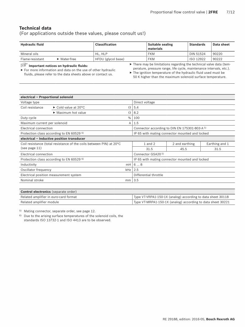
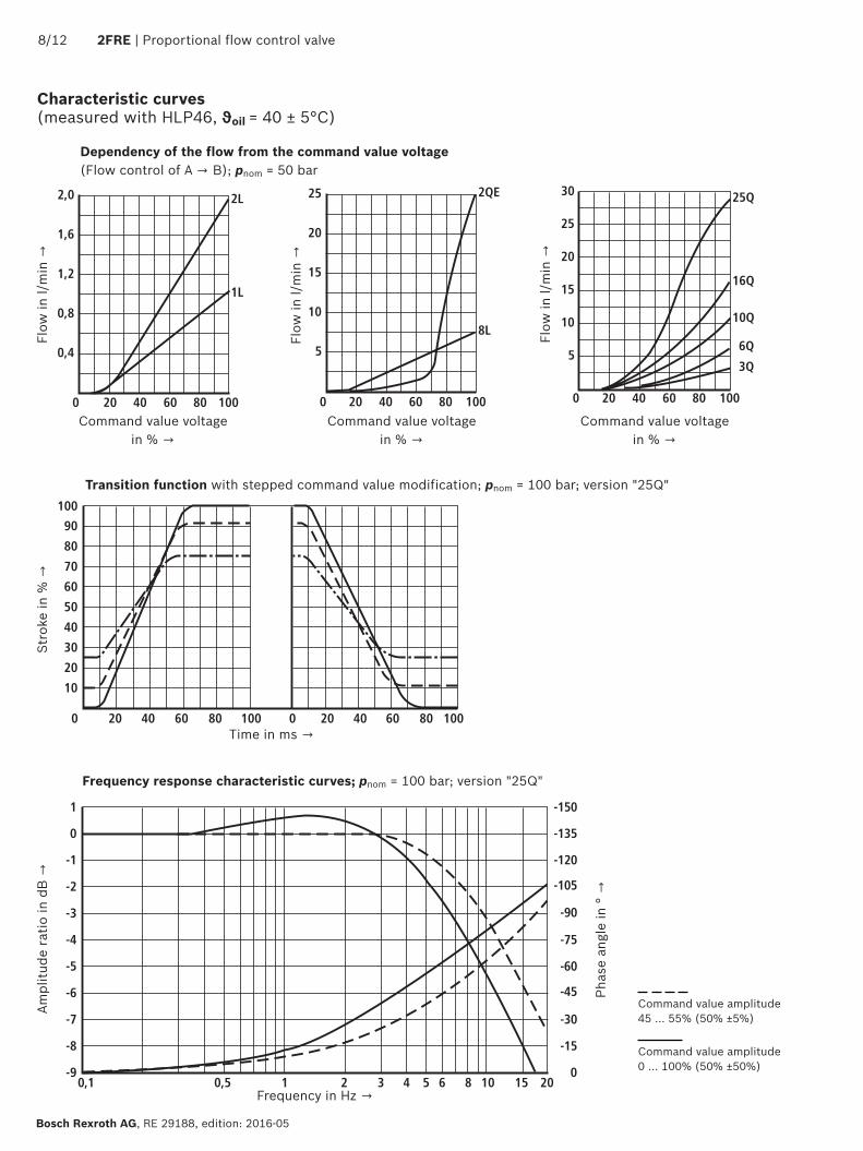
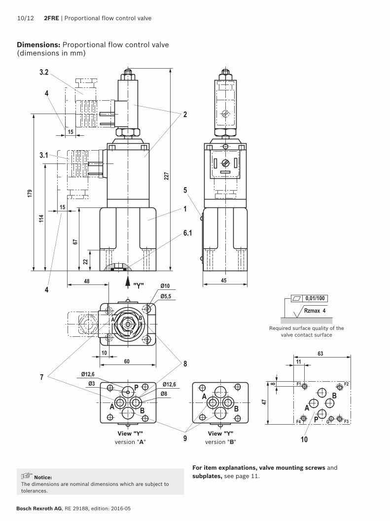
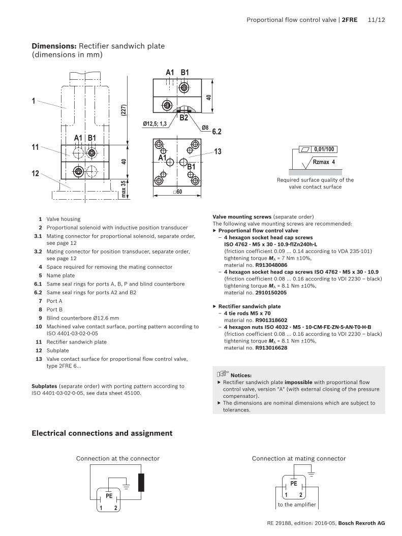
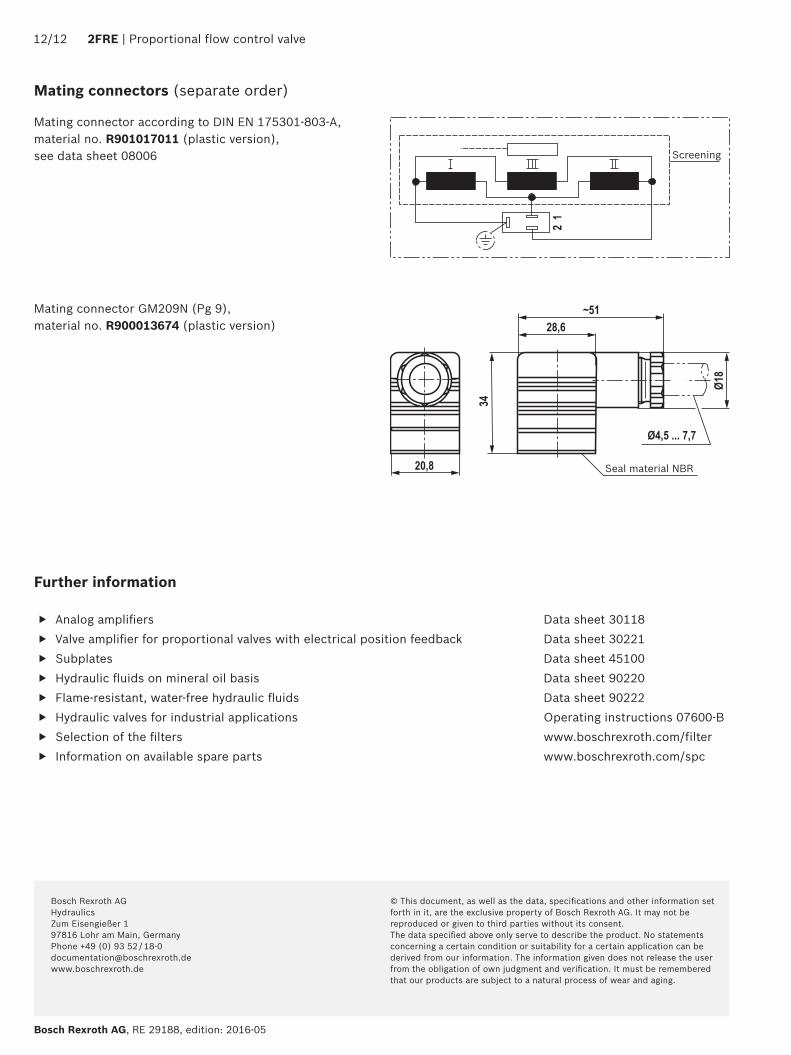