Embed Size (px)
Citation preview
PROPORTIONAL WEIRS BY CURVE-MILLINGS. H. Collins by F. R. Hore
Member C.S.A.E. Member C.S.A.E.
Engineering Science Department, Ontario Agricultural College, Guelpb, Ontario
INTRODUCTION
The form of a weir for which theflow is proportional to the head wasdiscovered by Rettger (1), and suchweirs have been used with water stagerecorders to measure the dischargefrom tile drains (2).
A drainage investigation may require the use of many flow-measuringstations. When proportional weirs areused, the machining of the curvedsurfaces becomes a problem. Handfiling is tedious and expensive, anddoes not lead to great accuracy. Thereare obvious advantages in machiningthe weirs so that they are all identical.Accordingly, a method was developedfor handling the job in an ordinarymilling machine.
The extension of this procedure tothe milling of plate cams for flat orroller followers is practical and easy.
MECHANICAL TECHNIQUE
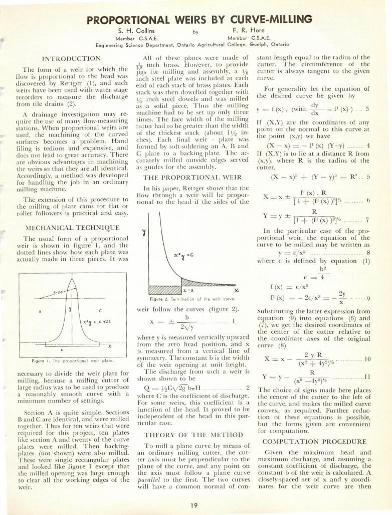
The usual form of a proportionalweir is shown in figure 1, and thedotted lines show how each plate wasactually made in three pieces. It was
R-ZS'T'
/1 C
\ x'iu ' oiit
A
F.gure I. 'l he proportional weir plate.
necessary to divide the weir plate formilling, because a milling cutter oflarge radius was to be used to producea reasonably smooth curve with aminimum number of settings.
Section A is quite simple. SectionsB and C are identical, and were milledtogether. Thus for ten weirs that wererequired for this project, ten plateslike section A and twenty of the curveplates were milled. Then backing-plates (not shown) were also milled.These were single rectangular platesand looked like figure 1 except thatthe milled opening was large enoughto clear all the working edges of theweir.
All of these plates were made of^ inch brass. However, to providejigs for milling and assembly, a i/ginch steel plate was included at eachend of each stack of brass plates. Eachstack was then dowelled together with14 inch steel dowels and was milledas a solid piece. Thus the millingmachine had to be set up only threetimes. The face width of the millingcutter had to be greater than the widthof the thickest stack (about ll/g inches). Each final weir - plate wasformed by soft-soldering an A, B andC plate to a backing-plate. The accurately milled outside edges servedas guides for the assembly.
THE PROPORTIONAL WEIR
In his paper, Rettger shows that theflow through a weir will be proportional to the head if the sides of the
Figure 2. Termination ot ihe we
weir follow the curves (figure 2).b
Vyi
where y is measured vertically upwardfrom the zero head position, and xis measured from a vertical line ofsymmetry. The constant b is the widthof the weir opening at unit height.
The discharge from such a weir isshown shown to be
Q = i/2CV2g"WH 2where C is the coefficient of discharge.For some weirs, this coefficient is afunction of the head. It proved to beindependent of the head in this particular case.
THEORY OF THE METHOD
To mill a plane curve by means ofan ordinary milling cutter, the cutter axis must be perpendicular to theplane of the curve, and any point onthe axis must follow a plane curveparallel to the first. The two curveswill have a common normal of con
19
stant length equal to the radius of thecutter. The circumference of the
cutter is always tangent to the givencurve.
For generality let the equation ofthe desired curve be given by
y==f(x), (with $L- - P(x) ) 3If (X,Y) are the coordinates of anypoint on the normal to this curve atthe point (x,y) we have
(X-x) = -P(x) (Y-y) 4If (X,Y) is to lie at a distance R from(x,y), where R is the radius of thecutter,
(X - x)2 + (Y - y)* = R>... 5
X-x-H fl(X)'R~ -[l+(P(x))Ta b
Y— •+• R= [1 + (f1 (x) )T> 7In the particular case of the pro
portional weir, the equation of thecurve to be milled may be written as
y = c/x2 8where c is defined by equation (1)
c = ~4~~
f(x) = c/x2
fi (x) = - 2c/x3 =-?L - .... 9Substituting the latter expression fromequation (9) into equations (6) and(7), we get the desired coordinates ofthe center of the cutter relative to
the coordinate axes of the originalcurve (8)
X= x- —-j \ R „. „ 10(x2 -f- 4y2)/2
Y= y- R 11(X2 -i-4y2)'^
The choice of signs made here placesthe centre of the cutter to the left of
the curve, and nrakes the milled curveconvex, as required. Further reduction of these equations is possible,but the forms given are convenientfor computation.
COMPUTATION PROCEDURE
Given the maximum head and
maximum discharge, and assuming aconstant coefficient of discharge, theconstant b of the weir is calculated. Aclosely-spaced set of x and y coordinates for the weir curve are then
tabulated. A cutter of as large a radius R as possible is chosen, and alist of coordinates of its center are
calculated from equations (10) and(11). The settings of the milling tablethat holds the work are obtained byadding constants to the X and Yvalues, and the settings will be moreaccurate if the stack of plates is firstmilled square with a given pair oftable settings.
ALLOWANCE FOR THE
MENISCUS
It is obviously impossible to extendthe weir curve out to infinity in thehorizontal direction, and in fact itshould be terminated by a verticalend at such a point that the meniscusbreaks before the curve itself is wetted. On the other hand, the proportionality will be lost if the area underthe curve is changed. It may be shownthat the area is preserved by loweringthe level bottom of the weir plate byan amount equal to the ordinate ofthe curve at the point where it isterminated (figure 2). For, the areaunder the curve from any point x =a to x = oo is given by
A =dx b2
'4a"
This area may be replaced by a rectangular area of width a and depth
b2rr" . which is just the ordinate of a
4a2
point on the curve at x = a.
It must be pointed out that thissubstitution is not exact, because thenew area is not under the same head
as the area that is replaced.
ROUGHNESS OF THE MILLED
CURVE
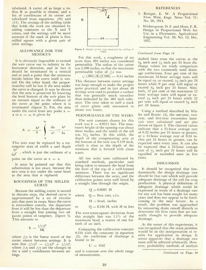
Because the milling cutter is movedin discrete steps, the desired curve isapproximated by a set of circulararcs that meet in cusps. Since the curveis everywhere convex, the departurefrom it will be less than the departurefrom a straight line joining two adjacent points of tangency. (figure 3).This amounts to
h (Asi!8R
where As is the linear travel of thecutter center between settings. It isseen that (As)2 = (Ax)2 + (Ay)2,where Ax and Ay are the changes inthe x and y coordinates between settings.
Figure 3. Height of the cusp produced by milling insteps.
For this work, a roughness of nomore than .001 inches was considered
permissible. The radius of the cutterwas 2.498 inches, so that the maximumpermissable value of As was
V (.001) (8) (2A9S) = 0.14 inchesThis distance between cutter settingswas large enough to make the projectquite practical, and in fact about 40settings were used to produce a surfacethat was generally much smootherthan indicated by the .001 inch tolerance. The time taken to mill a stack
of curve plates only amounted toabout two hours.
PERFORMANCE OF THE WEIRS
The weir constant chosen for this
work was b = 0.0314 feet. The max
imum height of the opening was aboutthree inches, and the width of the sillwas 31/2 inches. At this width, thedepth of the compensating area atthe bottom of the weir was 0.139 inch,which is close to the depth of themeniscus that is formed with clean
water.
All ten weirs were calibrated bystandard methods, particular carebeing taken to measure the head fromthe level of the top of a well-formedmeniscus. There was no significantdifference between the weirs, and thecalibration points were well fitted bya straight line through the origin.
Q = 0.0205 H
where Q = flow rate, c.f.s.
H = head, inches
or Q = 0.246 H, with H in feet
The root-mean-square deviation fromthis straight line was 1.1% of themaximum head, a matter of one fortieth of an inch.
Comparing the calibration constant0.246 with the constants in equation(2), the coefficient of discharge isfound to be
C = 0.62
and is constant over the whole rangeof measurement.
20
REFERENCES
1. Rettger, E. W. A ProportionalFlow Weir, Engr. News Vol. 71:No. 26, 1914.
2. Witherspoon, D. F. and Hore, F. R.Design of Proportional Weir forUse in a Flowmeter, AgriculturalEngineering Vol. 38, No. 12, Dec.1957.
Continued from Page 18
dashed lines cross the curves at the3/g inch and i/2 inch per 24 hour discharge values for ready comparisonwith the two commonly used drainage coefficients. Four per cent of themaximum 24-hour average rates willbe equal to, or exceed, y2 inch per 24hours while 9 per cent will equal orexceed ys inch per 24 hours. Similarly, 12 per cent of the maximum 12hour average rates will equal or exceed i/2 inch per 24 hours while 22per cent will equal or exceed y& inchper 24 hours.
Using a method described by Wis-ler and Brater (4), the one-year, two-year, and five-year recurrence intervals were calculated and are alsoshown in figure 3. The charted valuesindicate that a 24-hour average rateof 0.32 inches per 24 hours or greater,or a 12-hour average rate of 0.54 inches per 24 hours or greater, can beexpected once every year. It can alsobe expected that a 24-hour averagerate of l/, inch per 24 hours will beequalled or exceeded once in fiveyears.
DISCUSSION
It should be recognized that fundamentally the design drainage rateshould be that rate which will provideadequate drainage of the soil for cropproduction. A physical definition ofadequate drainage which could beexpressed in terms of a drainage ratefor any soil has been sought for manyyears and does not appear to be forthcoming in the near future. As aresult, the problem was approachedby measuring drain runoff directly todetermine the flow rates that are nor
mally thought to provide adequatedrainage.
At the outset of this experiment, itwas recognized that the main problemwould be in the interpretation of results for application in design. Itseems apparent that a drainage ratemust still be selected arbitrarily. However, probability methods of analysis
Continued on Page 38