Embed Size (px)
Citation preview
158 Modeling Brilliance GEMS & GEMOLOGY Fall 1998
he quality and value of faceted gem diamonds areoften described in terms of the “four C’s”: caratweight, color, clarity, and cut. Weight is the most
objective, because it is measured directly on a balance.Color and clarity are factors for which grading standardshave been established by GIA, among others. Cut, however,is much less tractable. Clamor for the standardization ofcut, and calls for a simple cut grading system, have beenheard sporadically over the last 25 years, gaining strengthrecently (Shor, 1993, 1997; Nestlebaum, 1996, 1997). Unlikecolor and clarity, for which diamond trading, consistentteaching, and laboratory practice have created a general con-sensus, there are a number of different systems for gradingcut in round brilliants. As discussed in greater detail later inthis article, these systems are based on relatively simpleassumptions about the relationship between the proportionsand appearance of the round brilliant diamond. Inherent inthese systems is the premise that there is one set (or a nar-row range) of preferred proportions for round brilliants, andthat any deviation from this set of proportions diminishesthe attractiveness of a diamond. In this article, we presentand discuss our findings with regard to the rather complexrelationship between cut proportions and brilliance.
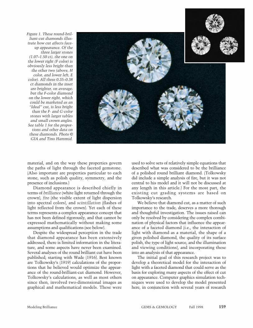
Diamond manufacturing has undergone considerablechange during this century. For the most part, diamonds arecut within very close proportion tolerances, both to saveweight while maximizing appearance and to account forlocal market preferences (Caspi, 1997). As shown in figure 1and table 1, however, differences in proportions can producenoticeable differences in appearance in round-brilliant-cutdiamonds. Within this single cutting style, there is substan-tial debate—and some strongly held views—about whichproportions yield the best face-up appearance (Federman,1997). Yet face-up appearance depends as well on manyintrinsic physical and optical properties of diamond as a
MODELING THE APPEARANCE OFTHE ROUND BRILLIANT CUT
DIAMOND: AN ANALYSIS OF BRILLIANCEBy T. Scott Hemphill, Ilene M. Reinitz, Mary L. Johnson, and James E. Shigley
ABOUT THE AUTHORS
Mr. Hemphill is research associate, and Dr. Shigleyis director, of GIA Research, Carlsbad, California.Dr. Reinitz is manager of Research and Develop-ment at the GIA Gem Trade Laboratory (GIA GTL),New York. Dr. Johnson is manager of Researchand Development at GIA GTL, Carlsbad.
Please see acknowledgments at the end of thearticle.
Gems & Gemology, Vol. 34, No. 3, pp. 158 –183© 1998 Gemological Institute of America
TOf the “four C’s,”cut has historically been themost complex to understand and assess. Thisarticle presents a three-dimensional mathemat-ical model to study the interaction of light witha fully faceted, colorless, symmetrical round-brilliant-cut diamond. With this model, onecan analyze how various appearance factors(brilliance, fire, and scintillation) depend onproportions. The model generates images and anumerical measurement of the optical efficien-cy of the round brilliant—called weighted lightreturn (WLR)—which approximates overallbrilliance. This article examines how WLR val-ues change with variations in cut proportions,in particular crown angle, pavilion angle, andtable size. The results of this study suggest thatthere are many combinations of proportionswith equal or higher WLR than “Ideal” cuts. Inaddition, they do not support analyzing cut byexamining each proportion parameter indepen-dently. However, because brilliance is just oneaspect of the appearance of a faceted diamond,ongoing research will investigate the addedeffects of fire and scintillation.
Modeling Brilliance GEMS & GEMOLOGY Fall 1998 159
material, and on the way these properties governthe paths of light through the faceted gemstone.(Also important are properties particular to eachstone, such as polish quality, symmetry, and thepresence of inclusions.)
Diamond appearance is described chiefly interms of brilliance (white light returned through thecrown), fire (the visible extent of light dispersioninto spectral colors), and scintillation (flashes oflight reflected from the crown). Yet each of theseterms represents a complex appearance concept thathas not been defined rigorously, and that cannot beexpressed mathematically without making someassumptions and qualifications (see below).
Despite the widespread perception in the tradethat diamond appearance has been extensivelyaddressed, there is limited information in the litera-ture, and some aspects have never been examined.Several analyses of the round brilliant cut have beenpublished, starting with Wade (1916). Best knownare Tolkowsky’s (1919) calculations of the propor-tions that he believed would optimize the appear-ance of the round-brilliant-cut diamond. However,Tolkowsky’s calculations, as well as most otherssince then, involved two-dimensional images asgraphical and mathematical models. These were
used to solve sets of relatively simple equations thatdescribed what was considered to be the brillianceof a polished round brilliant diamond. (Tolkowskydid include a simple analysis of fire, but it was notcentral to his model and it will not be discussed atany length in this article.) For the most part, theexisting cut grading systems are based onTolkowsky’s research.
We believe that diamond cut, as a matter of suchimportance to the trade, deserves a more thoroughand thoughtful investigation. The issues raised canonly be resolved by considering the complex combi-nation of physical factors that influence the appear-ance of a faceted diamond (i.e., the interaction oflight with diamond as a material, the shape of agiven polished diamond, the quality of its surfacepolish, the type of light source, and the illuminationand viewing conditions), and incorporating theseinto an analysis of that appearance.
The initial goal of this research project was todevelop a theoretical model for the interaction oflight with a faceted diamond that could serve as thebasis for exploring many aspects of the effect of cuton appearance. Computer graphics simulation tech-niques were used to develop the model presentedhere, in conjunction with several years of research
Figure 1. These round-bril-liant-cut diamonds illus-
trate how cut affects face-up appearance. Of the
three larger stones(1.07–1.50 ct), the one on
the lower right (F color) isobviously less bright than
the other two (above, Hcolor, and lower left, E
color). All three 0.35–0.38ct diamonds in the insetare brighter, on average;but the F-color diamond
on the lower right, whichcould be marketed as an“Ideal” cut, is less bright
than the F- and G-colorstones with larger tablesand small crown angles.
See table 1 for the propor-tions and other data on
these diamonds. Photo ©GIA and Tino Hammid.
160 Modeling Brilliance GEMS & GEMOLOGY Fall 1998
on how to express mathematically the interactionof light with diamond and also the various appear-ance concepts (i.e., brilliance, fire, and scintillation).Our model serves as a general framework for exam-ining cut issues; it includes mathematical represen-tations of both the shape of a faceted diamond andthe physical properties governing the movement oflight within the diamond. We plan to analyze theappearance aspects one at a time and then, ulti-mately, assemble the results in order to examinehow proportions affect the balance of brilliance, fire,and scintillation.
The general mathematical model presented inthis article uses computer graphics to examine theinteraction of light with a standard (58 facet) round-brilliant-cut diamond with a fully faceted girdle. Forany chosen set of proportions, our model can pro-duce images and numerical results for an appear-ance concept (by way of a mathematical expres-sion). To compare the appearance concepts of bril-liance, fire, and scintillation in round brilliants ofdifferent proportions, we need a quantity to mea-sure and a relative scale for each concept. A specificmathematical expression (with its built-in assump-tions and qualifications) that aids the measurementand comparison of a concept such as brilliance isknown as a metric. In this study, we derived a met-ric for brilliance that quantifies the amount of lightreturned from a modeled diamond for averaged illu-mination and viewing arrangements, as described
below. Although other factors (e.g., bodycolor orinclusions) may also influence how bright a particu-lar round brilliant appears, light return is an essen-tial feature of diamond brilliance.
In future reports on this project, we plan toaddress how fire and scintillation are affected byproportions. We also intend to examine how sym-metry, lighting conditions, and other factors affectall three of these appearance concepts. The overallgoal of this research is to provide a comprehensiveunderstanding of how cut affects the appearance ofa faceted diamond.
BACKGROUND
Early History. Diamond faceting began in about the1400s and progressed in stages toward the roundbrilliant we know today (see Tillander, 1966, 1995).In his early mathematical model of the behavior oflight in fashioned diamonds, Tolkowsky (1919) usedprinciples from geometric optics to explore howlight rays behave in a prism that has a high refrac-tive index. He then applied these results to a two-dimensional model of a round brilliant with a knife-edge girdle, using a single refractive index (that is,only one color of light), and plotted the paths ofsome illustrative light rays.
Tolkowsky assumed that a light ray is eithertotally internally reflected or totally refracted out ofthe diamond, and he calculated the pavilion angleneeded to internally reflect a ray of light enteringthe stone vertically through the table. He followedthat ray to the other side of the pavilion and foundthat a shallower angle is needed there to achieve asecond internal reflection. Since it is impossible tocreate substantially different angles on either side ofthe pavilion in a symmetrical round brilliant dia-mond, he next considered a ray that entered thetable at a shallow angle. Ultimately, he chose apavilion angle that permitted this ray to exitthrough a bezel facet at a high angle, claiming thatsuch an exit direction would allow the dispersion ofthat ray to be seen clearly. Tolkowsky also used thislimiting case of the ray that enters the table at a lowangle and exits through the bezel to choose a tablesize that he claimed would allow the most fire. Heconcluded by proposing angles and proportions for around brilliant that he believed best balanced thebrilliance and fire of a polished diamond, and thenhe compared them to some cutting proportions thatwere typical at that time. However, since Tol-kowsky only considered one refractive index, hecould not verify the extent to which any of his rays
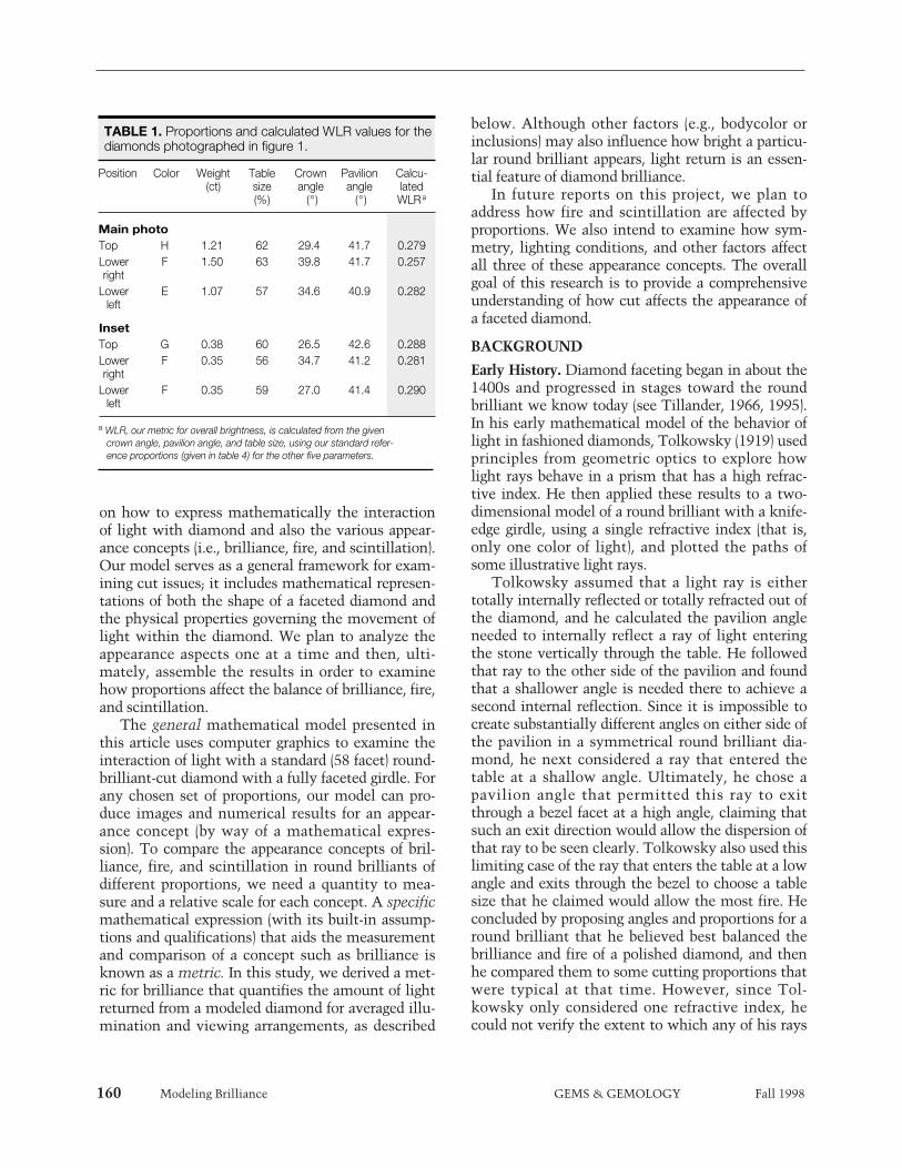
TABLE 1. Proportions and calculated WLR values for the diamonds photographed in figure 1.
Position Color Weight Table Crown Pavilion Calcu-(ct) size angle angle lated
(%) (°) (°) WLRa
Main photoTop H 1.21 62 29.4 41.7 0.279Lower F 1.50 63 39.8 41.7 0.257right
Lower E 1.07 57 34.6 40.9 0.282left
InsetTop G 0.38 60 26.5 42.6 0.288Lower F 0.35 56 34.7 41.2 0.281right
Lower F 0.35 59 27.0 41.4 0.290left
a WLR, our metric for overall brightness, is calculated from the givencrown angle, pavilion angle, and table size, using our standard refer-ence proportions (given in table 4) for the other five parameters.

Modeling Brilliance GEMS & GEMOLOGY Fall 1998 161
would be dispersed. Nor did he calculate the lightloss through the pavilion for rays that enter the dia-mond at high angles.
Over the next 80 years, other researchers famil-iar with this work produced their own analyses,with varying results (see table 2). It is interesting(and somewhat surprising) to realize that despite thenumerous possible combinations of proportions for astandard round brilliant, in many cases eachresearcher arrived at a single set of proportions thathe concluded produced an appearance that was supe-rior to all others. Currently, many gem grading labo-ratories and trade organizations that issue cut gradesuse narrow ranges of proportions to classify cuts,including what they consider to be best (table 3).
Several cut researchers, but not Tolkowsky, used“Ideal” to describe their sets of proportions, whichvary significantly, as seen in table 2. Today, in addi-tion to systems that incorporate “Ideal” in theirnames, many people use this term to refer to mea-surements similar to Tolkowsky’s proportions, butwith a somewhat larger table (which, at the samecrown angle, yields a smaller crown height percent-age). This is what we mean when we use “Ideal” inthis article.
Recent Appearance Models and Measurements. Wefound thorough descriptions of three computermodels of round brilliant diamonds in the literature.One model explored light return numerically(Tognoni, 1990); another produced a number ofmonochromatic images, each using a differentrefractive index, and some numerical output (Astricet al., 1992); but the third (Dodson, 1979) was simi-lar to our work in several ways. Using a three-dimensional model of a fully faceted round brilliantdiamond, Dodson devised metrics for brilliance,fire, and “sparkliness” (scintillation). His mathe-matical model employed a full sphere of approxi-mately diffuse illumination centered on the dia-mond’s table. His results were presented as graphsof brilliance, fire, and sparkliness for 120 proportioncombinations. They show the complex interdepen-dence of all three appearance aspects on pavilionangle, crown height, and table size. His model (aswell as that of Shannon and Wilson, as best we candetermine from the little published on it [Lawrence,1998; Shor, 1998]) is distinct from ours in that allrays emerging from the diamond were weightedequally. Three of Dodson’s results are given in table 2.
There are also computer-aided-design (CAD)software programs for creating gemstone cuts and
analyzing the effect of cut on the appearance of thefinished gemstone. (One of these, Gem-Cad, is mar-keted by Gemsoft Enterprises, Austin, Texas.)
These computer programs and mathematicalmodels use ray-tracing algorithms to produce visualimages of gemstones or numerical data about theirappearance, or both. However, each of the programsdescribed above excludes one or more of the startingassumptions that we employ here (e.g., wavelength-dependent refractive index, accounting for sec-ondary rays, weighing observer angles; see belowand Box A). Because of these differences, our com-puter graphics program is not directly comparableto these other programs. However, the optimal pro-portions predicted by those models can be assessedand compared using our metric for brilliance.
Commercial services are currently available thatclaim to measure the brilliance of fashioned stones.The measurements of brilliance provided byDiamond Profile (Portland, Oregon) are based ondigital video images through the crown of the dia-mond under a few controlled lighting conditions,which are then combined to generate graphicresults for that particular stone (Gilbertson andWalters, 1997; Gilbertson, 1998).
DESCRIPTION OF OUR MODELIn general, within a mathematical model, all of thefactors we consider important to diamond appear-ance—the diamond itself, its proportions and facetarrangement, and the lighting and observation con-ditions—can be carefully controlled, and fixed for agiven set of analyses. Such control is nearly impos-sible to achieve with actual diamonds. Furthermore,with this model we can examine thousands of setsof diamond proportions that would not be economi-cally feasible to create from diamond rough. Thus,use of a model allows us to explore how cut propor-tions affect diamond appearance in a more compre-hensive way than would be possible through obser-vation of actual round brilliants. However, everymathematical model incorporates some assump-tions, and these built-in conditions affect the natureof the results. (The modeled diamond used inTolkowsky’s [1919] analysis, for example, was two-dimensional and had a knife-edge girdle, which lim-ited the number and paths of light rays he couldconsider.)
Real diamonds will inevitably differ from themodel conditions because of inclusions, symmetrydeviations, and the like. Nevertheless, a theoreticalmodel provides a goal to reach toward: What is the
162 Modeling Brilliance GEMS & GEMOLOGY Fall 1998
best result—best brilliance, best fire, best balanceof the two, best scintillation, best weight retention,best combination—that can be achieved from a par-ticular piece of rough? In addition, a theoreticalunderstanding of the behavior of light in a faceteddiamond could help in the design of any instru-ment intended to measure optical performance inreal diamonds.
Finally, a model of the interaction of light with afaceted diamond can be used to compare and con-trast different metrics and different lighting andobservation conditions, as well as evaluate thedependence of those metrics on proportions, symme-try, or any other property of diamond included in themodel. In the following sections, we present theassumptions and methods on which our model isbased, and introduce our metric for brilliance.
Assumptions and Methods. The mathematicalmodel presented here creates a fresh structure forexamining nearly all aspects of the influence thatcut has on a diamond’s appearance. Box A providesthe assumptions on which the model is based: adetailed list of the physical properties included inthe model, a mathematical description of the pro-portions of the round brilliant, and a description ofthe lighting condition used in this study. The inclu-sion of these many physical properties distinguishesthis model from previous work, and the details ofthe lighting conditions affect the specific numericalvalues we present here. The model traces rays fromthe modeled light source through a mathematicalrepresentation of a round brilliant of any chosenproportions (referred to hereafter as the “virtual”diamond) to produce two kinds of results: (1) digitalimages of the virtual diamond, and (2) a numericalevaluation of an appearance concept (in this case,brilliance).
A digital image (see, e.g., figure 2), drawn fromthe perspective of our choice, is a two-dimensionalarray of picture elements (pixels), each of whichcomprises a small area of the virtual diamond. Wetraced up to one million rays of various colors foreach pixel in an image, to obtain convergence of thecolor and total brightness for that small area. As thecomputer traces the first few hundred rays, random-ly selecting wavelengths and angles of incidence,the computed brightness and color for a given pixelchange rapidly. Eventually, when enough differentdirections and wavelengths have been traced, thecomputed brightness and color settle down, or con-verge, to particular values, and tracing more rays
does not change these values. The resolution of theimage depends on our choice of the number of pix-els to compute for a particular image size. For mostof the images presented in this article, we calculat-ed the color and brightness of 65,536 pixels, requir-ing up to 65,000,000,000 traced rays.
The computer program employed is not a com-mercial product, but was written specifically forthis work by the first author. It was written in C, ascientific programming language. The program hasbeen run on a Pentium personal computer, on twomodels of Digital Equipment Corp.’s Alpha work-station, and on a dual Pentium II. If the convergencethresholds and choice of resolution are maintained,the hardware used to run the program does not alterthe results. The accuracy of the program, in generaland on different kinds of hardware, was verifiedwith a simple test problem for which we had com-puted a result manually. Further details of the raytracing and computational methods will be given byHemphill et al. (in preparation). These techniquesextend the methods described by Foley (1996).
Defining Metrics: Brilliance. Our aim is to use thismodel to explore how brilliance, fire, and scintilla-tion vary with the proportions of a round brilliantdiamond. We begin with brilliance for several rea-sons. First, brilliance is the aspect of diamondappearance that is most immediately noticed.Second, it is an aspect for which the desired out-come is obvious: Bright is good and dark is not.Last, most of the previous work investigating cutfocused on brilliance (see references in table 2), andit is this work that has fueled the current tradedebate about cut.
One advantage of using a computer model is thecapability it gives us to examine thousands of pro-portion variations. To make sense of so much data,however, we needed to define a metric for bril-liance, and use it to compare the performance of thedifferent proportion combinations. The GIADiamond Dictionary (1993, p. 28) defines brillianceas the “intensity of the internal and external reflec-tions of white light from the crown. . . .” A varietyof mathematical expressions can be created todescribe such light return. Each expression requiresexplicit or implicit assumptions about what consti-tutes brilliance and about light sources, viewinggeometry, response of the human eye, and responseof the human brain. As an example of this last con-sideration, should a mathematical definition of bril-liance represent one viewing geometry—that is, a
Modeling Brilliance GEMS & GEMOLOGY Fall 1998 163
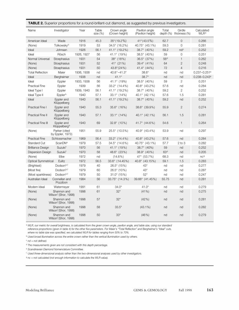
TABLE 2. Superior proportions for a round-brillant-cut diamond, as suggested by previous investigators.
Name Investigator Year Table Crown angle Pavilion angle Total Girdle Calculatedsize (%) (Crown height) (Pavilion height) depth (%) thickness (%) WLRa
American Ideal Wade 1916 45.3 35° (19.2%) 41° (43.5%) 62.7 0 0.266(None) Tolkowskyb 1919 53 34.5° (16.2%) 40.75° (43.1%) 59.3 0 0.281Ideal Johnsen 1926 56.1 41.1° (19.2%) 38.7° (40%) 59.2 ndc 0.252Ideal Rösch 1926, 1927 56 41.1° (19%) 38.5° (40%) 59 0 0.251Normal Universal Stoephasius 1931 54 38° (18%) 36.5° (37%) 56d 1 0.262(None) Stoephasius 1931 52 41° (21%) 39.4° (41%) 64 2 0.248(None) Stoephasius 1931 50 43.8° (24%) 41.4° (44%) 72 4 0.216Total Reflection Maier 1936, 1938 nd 40.8°–41.3° 38.6° nd nd 0.237–0.251a
Ideal Bergheimer 1938 nd 41.1° 38.7° nd nd 0.238–0.243a
Ideal Eppler 1933, 1938 56 41.1° (19%) 38.5° (40%) 59 2 0.251Practical Fine Eppler 1939 56 33.2° (14.4%) 40.8° (43.2%) 57.6 nd 0.284Ideal Type I Eppler 1939, 1940 56.1 41.1° (19.2%) 38.7° (40%) 59.2 2 0.252Ideal Type II Epplerb 1940 57.1 33.1° (14%) 40.1° (42.1%) 57.6 1.5 0.281Ideal Eppler and 1940 56.1 41.1° (19.2%) 38.7° (40%) 59.2 nd 0.252
KlüppelbergPractical Fine I Eppler and 1940 55.3 35.6° (16%) 38.6° (39.9%) 55.9 2 0.274
KlüppelbergPractical Fine II Eppler and 1940 57.1 33.1° (14%) 40.1° (42.1%) 56.1 1.5 0.281
KlüppelbergPractical Fine III Eppler and 1940 69 32.8° (10%) 41.7° (44.6%) 54.6 1 0.264
Klüppelbergb
(None) Parker (cited 1951 55.9 25.5° (10.5%) 40.9° (43.4%) 53.9 nd 0.297by Eppler, 1973)
Practical Fine Schlossmacher 1969 56.4 33.2° (14.4%) 40.8° (43.2%) 57.6 nd 0.284Standard Cut ScanDNe 1979 57.5 34.5° (14.6%) 40.75° (43.1%) 57.7 2 to 3 0.282Brilliance Design Suzuki f 1970 56 41.1° (19%) 38.7° (40%) 59 nd 0.252Dispersion Design Suzuki f 1970 58 48.6° (23%) 38.9° (40%) 63d nd 0.205(None) Elbe 1972 nd (14.6%) 47° (53.7%) 68.3 nd ncg
Optical Symmetrical Eulitz 1972 56.5 33.6° (14.45%) 40.8° (43.15%) 59.1 1.5 0.283(Brightest) Dodsonb,f 1979 40 26.5° (15%) 43° nd nd 0.277(Most fire) Dodsonb,f 1979 60 26.5° (10%) 43° nd nd 0.287(Most sparkliness) Dodsonb,f 1979 50 31.0° (15%) 52° nd nd 0.247Australian Ideal Connellan and 1984 56 33.75° (14.3%) 39.66° (41.45%) 55.75 nd 0.281
PozzibonModern Ideal Watermeyer 1991 61 34.0° 41.0° nd nd 0.279(None) Shannon and 1998 61 32° (41%) nd nd 0.275
Wilsonf (Shor, 1998)(None) Shannon and 1998 57 32° (42%) nd nd 0.281
Wilsonf (Shor, 1998)(None) Shannon and 1998 58 33.5° (43.1%) nd nd 0.282
Wilsonf (Shor, 1998)(None) Shannon and 1998 50 33° (46%) nd nd 0.279
Wilsonf (Shor, 1998)
a WLR, our metric for overall brightness, is calculated from the given crown angle, pavilion angle, and table size, using our standardreference proportions (given in table 4) for the other five parameters. For Maier’s “Total Reflection” and Bergheimer’s “Ideal” cuts,where no table size was specified, we calculated WLR for tables ranging from 50% to 70%.
b Used broad illumination across the entire crown rather than the vertical illumination used by others.c nd = not defined.d The measurements given are not consistent with this depth percentage.e Scandinavian Diamond Nomenclature Committee.f Used three-dimensional analysis rather than the two-dimensional analyses used by other investigators.g nc = not calculated (not enough information to calculate the WLR value).
164 Modeling Brilliance GEMS & GEMOLOGY Fall 1998
“snapshot”—or an average over many viewing situ-ations? We chose the latter approach.
Weighted Light Return. The metric we discuss inthis article is called weighted light return (WLR); itis specific to each set of modeled diamond propor-tions with the chosen illumination. After examin-ing a variety of possible metrics for brilliance, wedeveloped WLR to best represent the way the expe-rienced viewer sees a diamond, especially one
mounted in jewelry, with lighting that illuminatesthe stone from all around without excessive glare orshadow.
The WLR is a weighted sum of the amount oflight returned through the crown of the virtual dia-mond to all positions of observation above the gir-dle. Rather than using the total fraction of lightreturned through the crown for a fixed arrangementof the light source, diamond, and viewer, weweighed the relative importance of returned light
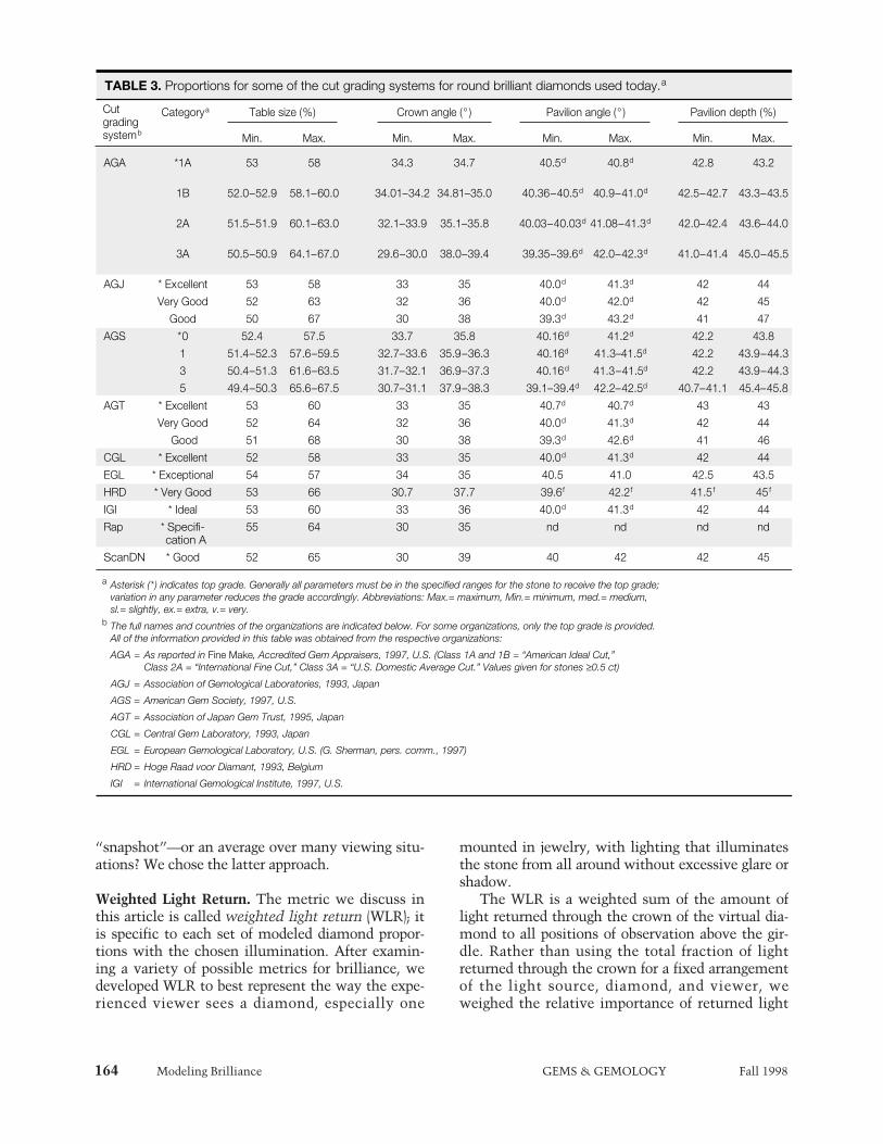
TABLE 3. Proportions for some of the cut grading systems for round brilliant diamonds used today.a
Categorya Table size (%) Crown angle (° ) Pavilion angle (° ) Pavilion depth (%)
Min. Max. Min. Max. Min. Max. Min. Max.
AGA *1A 53 58 34.3 34.7 40.5d 40.8d 42.8 43.2
1B 52.0–52.9 58.1–60.0 34.01–34.2 34.81–35.0 40.36–40.5d 40.9–41.0d 42.5–42.7 43.3–43.5
2A 51.5–51.9 60.1–63.0 32.1–33.9 35.1–35.8 40.03–40.03d 41.08–41.3d 42.0–42.4 43.6–44.0
3A 50.5–50.9 64.1–67.0 29.6–30.0 38.0–39.4 39.35–39.6d 42.0–42.3d 41.0–41.4 45.0–45.5
AGJ * Excellent 53 58 33 35 40.0d 41.3d 42 44
Very Good 52 63 32 36 40.0d 42.0d 42 45
Good 50 67 30 38 39.3d 43.2d 41 47
AGS *0 52.4 57.5 33.7 35.8 40.16d 41.2d 42.2 43.8
1 51.4–52.3 57.6–59.5 32.7–33.6 35.9–36.3 40.16d 41.3–41.5d 42.2 43.9–44.3
3 50.4–51.3 61.6–63.5 31.7–32.1 36.9–37.3 40.16d 41.3–41.5d 42.2 43.9–44.3
5 49.4–50.3 65.6–67.5 30.7–31.1 37.9–38.3 39.1–39.4d 42.2–42.5d 40.7–41.1 45.4–45.8
AGT * Excellent 53 60 33 35 40.7d 40.7d 43 43
Very Good 52 64 32 36 40.0d 41.3d 42 44
Good 51 68 30 38 39.3d 42.6d 41 46
CGL * Excellent 52 58 33 35 40.0d 41.3d 42 44
EGL * Exceptional 54 57 34 35 40.5 41.0 42.5 43.5
HRD * Very Good 53 66 30.7 37.7 39.6f 42.2f 41.5f 45f
IGI * Ideal 53 60 33 36 40.0d 41.3d 42 44
Rap * Specifi- 55 64 30 35 nd nd nd ndcation A
ScanDN * Good 52 65 30 39 40 42 42 45
a Asterisk (*) indicates top grade. Generally all parameters must be in the specified ranges for the stone to receive the top grade;variation in any parameter reduces the grade accordingly. Abbreviations: Max.= maximum, Min.= minimum, med.= medium,sl.= slightly, ex.= extra, v.= very.
b The full names and countries of the organizations are indicated below. For some organizations, only the top grade is provided.All of the information provided in this table was obtained from the respective organizations:
AGA = As reported in Fine Make, Accredited Gem Appraisers, 1997, U.S. (Class 1A and 1B = “American Ideal Cut,” Class 2A = “International Fine Cut,” Class 3A = “U.S. Domestic Average Cut.” Values given for stones ≥0.5 ct)
AGJ = Association of Gemological Laboratories, 1993, Japan
AGS = American Gem Society, 1997, U.S.
AGT = Association of Japan Gem Trust, 1995, Japan
CGL = Central Gem Laboratory, 1993, Japan
EGL = European Gemological Laboratory, U.S. (G. Sherman, pers. comm., 1997)
HRD = Hoge Raad voor Diamant, 1993, Belgium
IGI = International Gemological Institute, 1997, U.S.
Cut gradingsystemb
rays based on their exit direction. An experienceddiamond observer assesses the diamond primarilyon the basis of its face-up appearance, but also“rocks” the stone both to minimize the effect ofglare and to consider the stone from various angles,with the views closest to vertical (face-up) weighingthe most in this evaluation. We wanted the metricwe chose to behave like this assessment. Therefore,we wanted the contribution from rays that emergedstraight up to be much greater than that from rays
that exited horizontally, with a smooth variation asthe exit angle changed. We chose the square of thecosine function, applied to the exit angle measuredfrom the vertical, as a weighting factor (figure 3). Incontrast to this, both Dodson (1979) and Shannonand Wilson (Shor, 1998) considered all views of thediamond’s crown to be equally important, and sothey weighed much larger angles from the verticalfar more heavily than our metric does (or than expe-rienced observers do).
With this weighting function, we constrainedthe scale of the numbers for our metric between val-ues of 0 and 1. For instance, if we could construct avirtual diamond in which all light that entered leftthe crown straight up, it would have a WLR equalto 1.000; but if all the light that entered left thecrown at an angle of 25° to the horizontal, the WLRwould be 0.179. If light only exited from the crownhorizontally (or no light left through the crown), theWLR would be 0. Similarly, if half the light passedout of the crown at 45°, one fourth exited at 25°,and the remaining fourth was horizontal, the WLRwould equal 0.294. This weighting function empha-sizes the angle at which a light ray exits the virtualdiamond, rather than which facet the ray exits.
Note that we excluded glare—that is, any lightdirectly reflected from the top surface—from theWLR value (a difference from the GIA DiamondDictionary definition of brilliance). We made thissimple change in our computer program to guaran-tee that any trends in the WLR data were not sim-ply due to an increased area of the crown acting likea front-surface reflector. However, this is also a rea-sonable change to the metric, since when experi-enced observers “rock” a diamond, they mentallycorrect for the effects of glare. (We also checked ourresults with glare included and found that althoughthe WLR values increased across the whole range ofproportions, the relative variation was essentiallyunchanged.)
We systematically explored the dependence ofWLR on the eight proportion parameters that definethe perfectly symmetrical round brilliant diamond(again, see Box A) by changing one or more of theseparameters across the ranges given in table 4 andcomputing the WLR for each set of proportions.Although ideally we would have liked to examineall the interactions between WLR and the eightparameters, this was not practical given existingcomputer hardware. If we were interested inthe co-variation of, say, 20 values for each ofthe eight parameters, we would require 208 =
Modeling Brilliance GEMS & GEMOLOGY Fall 1998 165
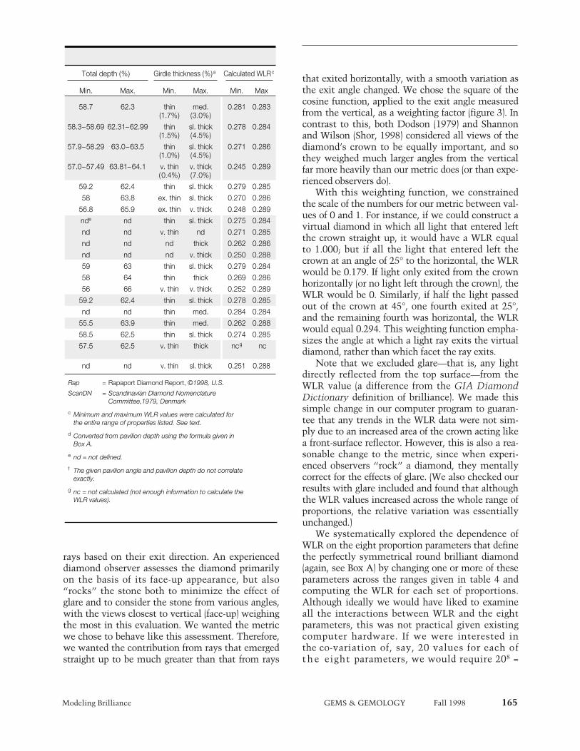
Total depth (%) Girdle thickness (%)a Calculated WLRc
Min. Max. Min. Max. Min. Max
58.7 62.3 thin med. 0.281 0.283(1.7%) (3.0%)
58.3–58.69 62.31–62.99 thin sl. thick 0.278 0.284(1.5%) (4.5%)
57.9–58.29 63.0–63.5 thin sl. thick 0.271 0.286(1.0%) (4.5%)
57.0–57.49 63.81–64.1 v. thin v. thick 0.245 0.289(0.4%) (7.0%)
59.2 62.4 thin sl. thick 0.279 0.285
58 63.8 ex. thin sl. thick 0.270 0.286
56.8 65.9 ex. thin v. thick 0.248 0.289
nde nd thin sl. thick 0.275 0.284
nd nd v. thin nd 0.271 0.285
nd nd nd thick 0.262 0.286
nd nd nd v. thick 0.250 0.288
59 63 thin sl. thick 0.279 0.284
58 64 thin thick 0.269 0.286
56 66 v. thin v. thick 0.252 0.289
59.2 62.4 thin sl. thick 0.278 0.285
nd nd thin med. 0.284 0.284
55.5 63.9 thin med. 0.262 0.288
58.5 62.5 thin sl. thick 0.274 0.285
57.5 62.5 v. thin thick ncg nc
nd nd v. thin sl. thick 0.251 0.288
Rap = Rapaport Diamond Report, ©1998, U.S.
ScanDN = Scandinavian Diamond Nomenclature Committee,1979, Denmark
c Minimum and maximum WLR values were calculated forthe entire range of properties listed. See text.
d Converted from pavilion depth using the formula given in Box A.
e nd = not defined.
f The given pavilion angle and pavilion depth do not correlateexactly.
g nc = not calculated (not enough information to calculate theWLR values).
166 Modeling Brilliance GEMS & GEMOLOGY Fall 1998
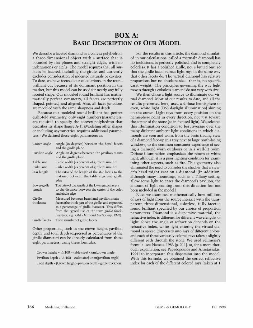
We describe a faceted diamond as a convex polyhedron,a three-dimensional object with a surface that isbounded by flat planes and straight edges, with noindentations or clefts. The model requires that all sur-faces be faceted, including the girdle, and currentlyexcludes consideration of indented naturals or cavities.To date, we have focused our calculations on the roundbrilliant cut because of its dominant position in themarket, but this model can be used for nearly any fullyfaceted shape. Our modeled round brilliant has mathe-matically perfect symmetry; all facets are perfectlyshaped, pointed, and aligned. Also, all facet junctionsare modeled with the same sharpness and depth.
Because our modeled round brilliant has perfecteight-fold symmetry, only eight numbers (parameters)are required to specify the convex polyhedron thatdescribes its shape (figure A-1). (Modeling other shapesor including asymmetries requires additional parame-ters.) We defined these eight parameters as:
Crown angle Angle (in degrees) between the bezel facetsand the girdle plane
Pavilion angle Angle (in degrees) between the pavilion mainsand the girdle plane
Table size Table width (as percent of girdle diameter)Culet size Culet width (as percent of girdle diameter)Star length The ratio of the length of the star facets to the
distance between the table edge and girdleedge
Lower-girdle The ratio of the length of the lower-girdle facetslength to the distance between the center of the culet
and girdle edgeGirdle Measured between bezel and pavilion mainthickness facets (the thick part of the girdle) and expressed
as a percentage of girdle diameter. This differsfrom the typical use of the term girdle thick-ness (see, e.g., GIA Diamond Dictionary, 1993)
Girdle facets Total number of girdle facets
Other proportions, such as the crown height, paviliondepth, and total depth (expressed as percentages of thegirdle diameter) can be directly calculated from theseeight parameters, using these formulas:
Crown height = 1⁄2(100 − table size) × tan(crown angle)
Pavilion depth = 1⁄2(100 − culet size) × tan(pavilion angle)
Total depth = (Crown height + pavilion depth + girdle thickness)
For the results in this article, the diamond simulat-ed in our calculations (called a “virtual” diamond) hasno inclusions, is perfectly polished, and is completelycolorless. It has a polished girdle, not a bruted one, sothat the girdle facets refract light rays in the same waythat other facets do. The virtual diamond has relativeproportions but no absolute size—that is, no specificcarat weight. (The principles governing the way lightmoves through a colorless diamond do not vary with size.)
We then chose a light source to illuminate our vir-tual diamond. Most of our results to date, and all theresults presented here, used a diffuse hemisphere ofeven, white light (D65 daylight illumination) shiningon the crown. Light rays from every position on thehemisphere point in every direction, not just towardthe center of the stone (as in focused light). We selectedthis illumination condition to best average over themany different ambient light conditions in which dia-monds are seen and worn, from the basic trading viewof a diamond face-up in a tray next to large north-facingwindows, to the common consumer experience of see-ing a diamond worn outdoors or in a well-lit room.Diffuse illumination emphasizes the return of whitelight, although it is a poor lighting condition for exam-ining other aspects, such as fire. This geometry alsoeliminated the need to consider the shadow that a view-er’s head might cast on a diamond. (In addition,although many mountings, such as a Tiffany setting,allow some light to enter the diamond’s pavilion, theamount of light coming from this direction has notbeen included in the model.)
Next we examined mathematically how millionsof rays of light from the source interact with the trans-parent, three-dimensional, colorless, fully facetedround brilliant specified by our choice of proportionparameters. Diamond is a dispersive material; therefractive index is different for different wavelengths oflight. Since the angle of refraction depends on therefractive index, white light entering the virtual dia-mond is spread (dispersed) into rays of different colors,and each of these variously colored rays takes a slightlydifferent path through the stone. We used Sellmeier’sformula (see Nassau, 1983 [p. 211]; or, for a more thor-ough explanation, see Papadopoulos and Anastassakis,1991) to incorporate this dispersion into the model.With this formula, we obtained the correct refractiveindex for each of the different colored rays (taken at 1
BOX A: BASIC DESCRIPTION OF OUR MODEL

Modeling Brilliance GEMS & GEMOLOGY Fall 1998 167
nm intervals from 360 to 830 nm), so that each raycould be traced (followed) individually as it movedthrough the stone. Some rays follow simple paths withonly a few internal reflections, while others follow com-plex three-dimensional paths (figure A-2). The color dis-tribution of these rays was scaled to the response of thehuman eye, using “CIE X,Y,Z” color functions as part ofthe convergence criteria (Wright, 1969).
Each time a ray strikes a facet, some combinationof reflection and refraction takes place, depending onthe angle between the ray and the facet, the refractiveindex at the wavelength of the ray, and the polarizationstate of the ray. Although the rays from our diffusehemisphere light source are initially unpolarized, alight ray becomes polarized each time it bounces off afacet. The degree and direction of polarization affecthow much of the ray is internally reflected, rather thanrefracted out the next time it intersects a facet. (Forexample, about 18% of a light ray approaching a dia-mond facet from the inside at an angle of 5° from theperpendicular is reflected, regardless of the polariza-tion. But at an incidence of 70°, rays with polarizationparallel to the plane of incidence are completely lostfrom the stone, while 55% of a ray polarized perpendic-ular to the plane of incidence is reflected back into thestone.) The model traces each ray until 99.95% of itsincident energy has exited the diamond. The end resultof this ray tracing can be either an image of the virtualdiamond or the value of a metric for that stone, orboth.
63 64 1 2
GIRDLE DIAMETER = 1
PAVILION ANGLE
GIRDLETHICKNESS
CROWN ANGLE
PAVILIONDEPTH
CROWNHEIGHT
GIRDLE FACETS
TABLE SIZE
CULET SIZE
LOWER GIRDLE LENGTH
0
10
1
STAR LENGTH
Figure A-2. Some of the light rays that pass throughthe virtual diamond follow complicated paths. Here,we show the track of one light ray within a round bril-liant diamond, as calculated by our mathematicalmodel. This ray reflects in multiple directions. Not alllight rays reflect this many times, but most take athree-dimensional path through the diamond. Thechief inadequacy of a two-dimensional analysis is thatlight rays must be confined to a single plane.
Figure A-1. We used eight parameters—varied acrossthe range given in table 4—to define our geometricmodel of the round brilliant shape. (a) All linear dis-tances in this profile view can be described as a per-centage of the girdle diameter. The enlarged view of thegirdle is centered on the position where we measuredthe girdle thickness. (b) In this view of the table, thestar length is shown at 50%, so that the star facetsextend halfway from the table to the girdle (whenviewed from straight above). (c) In this view of thepavilion, the lower-girdle length is shown at 75%, sothat the lower girdle facets extend three-fourths of thedistance from the girdle to the culet (when viewed fromstraight below).

168 Modeling Brilliance GEMS & GEMOLOGY Fall 1998
Figure 2. Left: This oblique profile view of a standard round brilliant—a “virtual” diamond (1024 × 1024pixels)—with commercially acceptable proportions was calculated with our mathematical model using apartial sphere of white light for illumination. This computer-generated image shows how the model cap-tures many of the appearance aspects of an actual diamond, such as three-dimensionality, transparency,facet arrangement, overall light return (brilliance), pattern of light and dark reflections, and dispersion(fire). Center: This digital image (512 × 512 pixels) of a standard round brilliant was calculated face-up witha diffuse hemisphere of white light for illumination. The proportions, used for reference throughout thispaper, are: 34° crown angle, 40.5° pavilion angle, 56% table, 3% girdle (at the thickest places, which corre-sponds to a medium girdle thickness) with 64 girdle facets, 50% star length, 75% lower-girdle length, and0.5% (“very small”) culet. Right: An actual diamond with proportions comparable to the virtual diamondin the center was photographed in diffuse white light using a hemispherical reflector. This diamond has a34.5° crown angle, 40.9° pavilion angle, 55% table, faceted girdle of medium thickness, 38.7% star length,very small culet, and excellent symmetry. The lower girdle length was not measured. The diffuse illumina-tion reduces the overall contrast, allowing us to examine brilliance separately from the other appearanceaspects. Photo by Vincent Cracco.
20 × 20 × 20 × 20 × 20 × 20 × 20 × 20 = 25.6 billioncomputations, which was not feasible at this time.(Note that each of these computations wouldrequire tracing the previously mentioned 65 billionlight rays.)
Direct observation of actual diamonds indicatesthat the overall shape of the round brilliant is pri-marily determined by three parameters: crownangle, pavilion angle, and table size. (These werethe only parameters Tolkowsky considered in hisanalysis.) Therefore, we examined in detail thechanges in WLR as these three important parame-ters varied together, while holding the others con-stant. We used about 20 values for each parameter,within the ranges given in table 4. This yieldedalmost 20,000 proportion combinations, with eachcalculation requiring several minutes of computertime. We also analyzed the extent to which theother five parameters affect diamond appearance byvarying each of them individually while holding theother seven parameters constant at the referencevalues (again, see table 4).
For each chosen set of cut parameters, our com-puter program can calculate a single WLR value or
an image of the virtual diamond (or both). The WLRvalues can be compared to one another for differentsets of proportions. The bulk of this discussion willfocus on the analysis of these WLR values for vari-ous ranges of parameters taken singly and in combi-nation. Table 4 lists these ranges for the 20,122combinations of cut proportions that we haveexamined for this study. In addition to the WLR val-ues generated for these virtual diamonds, we alsoexamined proportion data obtained from 67,621actual diamonds measured and graded in the GIAGem Trade Laboratory (GIA GTL), and we calculat-ed WLR values for virtual diamonds with thesecombinations of proportions (see Box B).
As a convenience for the readers of this article,for comparison purposes only, we have placed WLRvalues into five general categories:
High (bright): WLR values above 0.285Moderately high: WLR values from 0.280 to 0.285Typical: WLR values from 0.270 to 0.280Moderately low: WLR values from 0.265 to 0.270Low (dark): WLR values below 0.265
Modeling Brilliance GEMS & GEMOLOGY Fall 1998 169
These groups should not be taken as WLR orbrilliance “grades.” The authors strongly cautionagainst such usage. These terms are provided as aconvenience only, to compare the relative bright-ness of the virtual diamonds in the different WLRranges.
As seen in figure 1, large differences in WLR cor-relate to perceptible differences in the overallbrightness of actual diamonds. Even over therestricted WLR range in the inset to figure 1, thedarkest and brightest stones differ by almost 0.010;this difference is also easily perceived by a trainedviewer. In our experience, WLR differences of 0.005are discernable among stones with the same colorand clarity grades when examined with controlledobservation environments and lighting conditions.
RESULTS
Images and WLR. The calculations made with ourmodel produced realistic digital images of virtualdiamonds (again, see figure 2). These computer-gen-erated images reproduce the patterns of light anddark seen in actual round brilliant diamonds underlighting conditions similar to those used with themodel, although the light-and-dark patterns aremore symmetrical than those seen in most real dia-monds. During the course of this research, we gen-erated a variety of digital images, from different per-spectives and with different lighting conditions.However, the details of how brilliance changes withproportions can be better studied by comparing ametric, such as WLR values, than by visually exam-ining thousands of images.
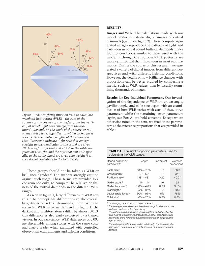
Results for Key Individual Parameters. Our investi-gation of the dependence of WLR on crown angle,pavilion angle, and table size began with an exami-nation of how WLR varies with each of these threeparameters while the remaining seven parameters(again, see Box A) are held constant. Except whereotherwise noted in the text, we fixed these parame-ters at the reference proportions that are provided intable 4.
90°90°
65°
65°65°
45°
45° 45°
10°25°
50%
100%
100%
82%
82%82%
3%
50%
50%
18%
Figure 3. The weighting function used to calculateweighted light return (WLR)—the sum of thesquares of the cosines of the angles (from the verti-cal) at which light rays emerge from the dia-mond—depends on the angle of the emerging rayto the table plane, regardless of which crown facetit exits. As the relative lengths of the arrows onthis illustration indicate, light rays that emergestraight up (perpendicular to the table) are given100% weight, rays that exit at 45° to the table aregiven 50% weight, and the rays that exit at 0° (par-allel to the girdle plane) are given zero weight (i.e.,they do not contribute to the total WLR).
TABLE 4. The eight proportion parameters used for calculating the WLR values.
Round-brilliant-cut Rangeb Increment Referenceparametersa proportions
Table sizec 50% – 75% 1% 56%Crown anglec 19° – 50° 1° 34°Pavilion anglec 38° – 43° 0.25° 40.5°
Girdle facetsd 16 – 144 16 64Girdle thicknessd 1.8% – 4.0% 0.2% 3.0%Star lengthd 5% – 95% 1% 50%Lower-girdle lengthd 50% – 95% 5% 75%Culet sized 0% – 20% 0.5% 0.5%
a These eight parameters are defined in Box A. b These ranges extend beyond the widest range for diamonds nor-
mally encountered in the trade today. c These three parameters were varied together while the other five
were held at the reference proportions. A set of calculations was also made at the reference proportions with crown angle varying from 1° to 50°.
d These five parameters were varied individually. For each one, the other seven parameters were held constant at the reference pro-portions.
170 Modeling Brilliance GEMS & GEMOLOGY Fall 1998
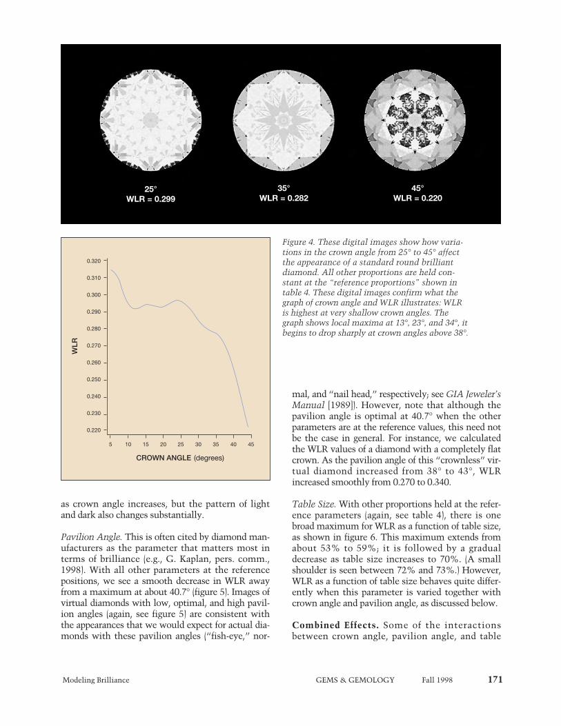
Crown Angle. Of the three parameters, changingthe crown angle produced the greatest variation inWLR. In general, WLR increases as crown angledecreases; but, as figure 4 shows, there are threelocal maxima in WLR across the range of angles(that is, WLR varies up and down with changes incrown angle). These results suggest that, at the ref-erence proportions, a diamond with a 23° crownangle is brighter than a stone with any other crownangle greater than 10°. However, other considera-tions may dictate that a diamond must have acrown angle above a certain value (such as reduceddurability with a thin to medium girdle and a crown
flatter than, say, 25°; see, e.g., Crowningshield andMoses, 1997). Ironically, the highest WLR valuesare obtained for a round brilliant with no crown atall. It is interesting to note that the question ofreduced durability with a shallower crown was dis-cussed in Gems & Gemology in 1936, although atthat time it was the “modern” trend toward anglesof 34.5° (from the steeper angles cut previously) thatraised concern (Ware, 1936).
Figure 4 also shows images of virtual diamondsthat have crown angles of 25°, 35°, and 45°, with allother parameters at the reference proportions listedin table 4. The overall brightness clearly decreases
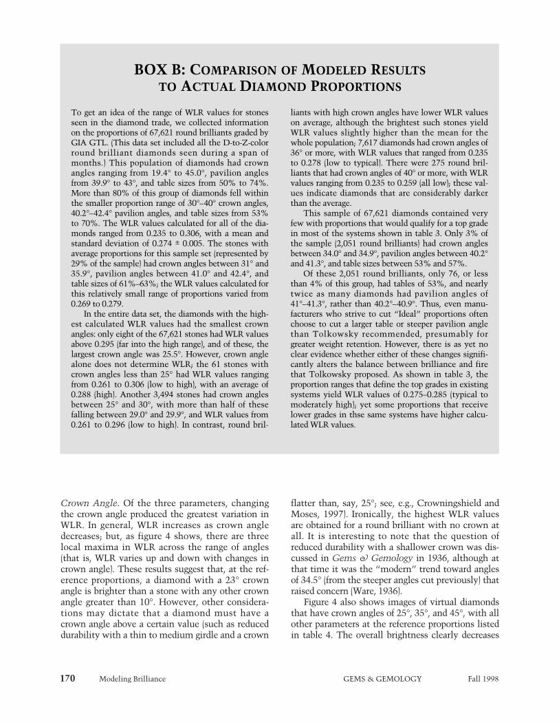
To get an idea of the range of WLR values for stonesseen in the diamond trade, we collected informationon the proportions of 67,621 round brilliants graded byGIA GTL. (This data set included all the D-to-Z-colorround brilliant diamonds seen during a span ofmonths.) This population of diamonds had crownangles ranging from 19.4° to 45.0°, pavilion anglesfrom 39.9° to 43°, and table sizes from 50% to 74%.More than 80% of this group of diamonds fell withinthe smaller proportion range of 30°–40° crown angles,40.2°–42.4° pavilion angles, and table sizes from 53%to 70%. The WLR values calculated for all of the dia-monds ranged from 0.235 to 0.306, with a mean andstandard deviation of 0.274 ± 0.005. The stones withaverage proportions for this sample set (represented by29% of the sample) had crown angles between 31° and35.9°, pavilion angles between 41.0° and 42.4°, andtable sizes of 61%–63%; the WLR values calculated forthis relatively small range of proportions varied from0.269 to 0.279.
In the entire data set, the diamonds with the high-est calculated WLR values had the smallest crownangles: only eight of the 67,621 stones had WLR valuesabove 0.295 (far into the high range), and of these, thelargest crown angle was 25.5°. However, crown anglealone does not determine WLR; the 61 stones withcrown angles less than 25° had WLR values rangingfrom 0.261 to 0.306 (low to high), with an average of0.288 (high). Another 3,494 stones had crown anglesbetween 25° and 30°, with more than half of thesefalling between 29.0° and 29.9°, and WLR values from0.261 to 0.296 (low to high). In contrast, round bril-
liants with high crown angles have lower WLR valueson average, although the brightest such stones yieldWLR values slightly higher than the mean for thewhole population; 7,617 diamonds had crown angles of36° or more, with WLR values that ranged from 0.235to 0.278 (low to typical). There were 275 round bril-liants that had crown angles of 40° or more, with WLRvalues ranging from 0.235 to 0.259 (all low); these val-ues indicate diamonds that are considerably darkerthan the average.
This sample of 67,621 diamonds contained veryfew with proportions that would qualify for a top gradein most of the systems shown in table 3. Only 3% ofthe sample (2,051 round brilliants) had crown anglesbetween 34.0° and 34.9°, pavilion angles between 40.2°and 41.3°, and table sizes between 53% and 57%.
Of these 2,051 round brilliants, only 76, or lessthan 4% of this group, had tables of 53%, and nearlytwice as many diamonds had pavilion angles of41°–41.3°, rather than 40.2°–40.9°. Thus, even manu-facturers who strive to cut “Ideal” proportions oftenchoose to cut a larger table or steeper pavilion anglethan Tolkowsky recommended, presumably forgreater weight retention. However, there is as yet noclear evidence whether either of these changes signifi-cantly alters the balance between brilliance and firethat Tolkowsky proposed. As shown in table 3, theproportion ranges that define the top grades in existingsystems yield WLR values of 0.275–0.285 (typical tomoderately high); yet some proportions that receivelower grades in thse same systems have higher calcu-lated WLR values.
BOX B: COMPARISON OF MODELED RESULTSTO ACTUAL DIAMOND PROPORTIONS
Modeling Brilliance GEMS & GEMOLOGY Fall 1998 171
as crown angle increases, but the pattern of lightand dark also changes substantially.
Pavilion Angle. This is often cited by diamond man-ufacturers as the parameter that matters most interms of brilliance (e.g., G. Kaplan, pers. comm.,1998). With all other parameters at the referencepositions, we see a smooth decrease in WLR awayfrom a maximum at about 40.7° (figure 5). Images ofvirtual diamonds with low, optimal, and high pavil-ion angles (again, see figure 5) are consistent withthe appearances that we would expect for actual dia-monds with these pavilion angles (“fish-eye,” nor-
mal, and “nail head,” respectively; see GIA Jeweler’sManual [1989]). However, note that although thepavilion angle is optimal at 40.7° when the otherparameters are at the reference values, this need notbe the case in general. For instance, we calculatedthe WLR values of a diamond with a completely flatcrown. As the pavilion angle of this “crownless” vir-tual diamond increased from 38° to 43°, WLRincreased smoothly from 0.270 to 0.340.
Table Size. With other proportions held at the refer-ence parameters (again, see table 4), there is onebroad maximum for WLR as a function of table size,as shown in figure 6. This maximum extends fromabout 53% to 59%; it is followed by a gradualdecrease as table size increases to 70%. (A smallshoulder is seen between 72% and 73%.) However,WLR as a function of table size behaves quite differ-ently when this parameter is varied together withcrown angle and pavilion angle, as discussed below.
Combined Effects. Some of the interactionsbetween crown angle, pavilion angle, and table
Figure 4. These digital images show how varia-tions in the crown angle from 25° to 45° affectthe appearance of a standard round brilliantdiamond. All other proportions are held con-stant at the “reference proportions” shown intable 4. These digital images confirm what thegraph of crown angle and WLR illustrates: WLRis highest at very shallow crown angles. Thegraph shows local maxima at 13°, 23°, and 34°, itbegins to drop sharply at crown angles above 38°.
403020
CROWN ANGLE (degrees)
WLR
10 15 453525
0.220
0.230
0.240
0.250
0.260
0.270
0.280
0.290
0.300
0.310
0.320
5
25°WLR = 0.299
35°WLR = 0.282
45°WLR = 0.220

172 Modeling Brilliance GEMS & GEMOLOGY Fall 1998
size—and their joint effects on WLR values—can beseen when these proportion parameters are exam-ined two at a time. One way to visualize theseeffects is to draw them to look like a topographicmap (which shows the differences in elevation of anarea of land). We can draw subsets of the data ascross-sections (slices) through the data set with oneparameter held constant, and the WLR values canthen be expressed as contours. These cross-sectionscan be read in the same manner as topographicmaps; but instead of mountains, these “peaks”show proportion combinations that produce thehighest calculated WLR values for diamonds withina small range of proportions.
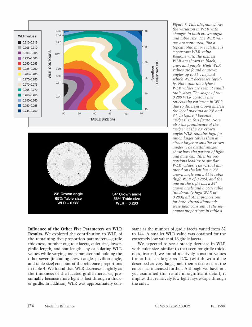
As illustrated in figure 7, when the crown angleand table size are varied together, the WLR changesin an unexpected fashion. There are “ridges” at
crown angles of 23° and 34°. Along these ridges,round brilliants with large tables show unexpected-ly high WLR values: For instance, for a 40.5° pavil-ion angle, a virtual diamond with a 65% table and a23° crown angle returns more light (high WLR of0.288) than one with a 56% table and a 34° crown(moderately high WLR of 0.283; again, see figure 7).Although the first of these stones is not a typicalcommercial cut, crown angles this low are some-times seen at GIA GTL. In addition, at crown anglesup to 37°, the table size has a significant influenceon WLR; in general, WLR increases as table sizedecreases within this range.
When we attempt to illustrate the effects of allthree parameters at the same time, the limitationsof graphing on two-dimensional paper are readilyapparent. The projection of a “three-dimensional
0.282
0.280
0.278
0.276
0.274
38 39 424140 43
PAVILION ANGLE (degrees)
WLR
Figure 5. Variations in pavilion angle also affectthe appearance of a faceted diamond. These vir-tual diamonds have pavilion angles of 38°,40.5°, and 43°; all other parameters are set tothe reference proportions (table 4). Althoughdiffuse illumination reduces the contrast in allthree images, they do illustrate well-knownoptical effects, including the “fish-eye” thatresults from a very shallow pavilion (far left),and the “nail head” caused by a very deeppavilion (far right). The graph of WLR as a func-tion of pavilion angle (with all other parametersat reference proportions) shows a maximum ata pavilion angle of 40.7°.
38°WLR = 0.272
40.5°WLR = 0.282
43°WLR = 0.270
Modeling Brilliance GEMS & GEMOLOGY Fall 1998 173
graph” in figure 8, for example, shows contours ofconstant WLR against crown angle, pavilion angle,and table size. This figure shows clearly that thehigher-value WLR surfaces have a complex depen-dence on the combination of these three parame-ters. In particular, the white contour (WLR of0.275–0.280) is concave as well as convex, anddefines a broad range of proportions that have thesame WLR values. However, only a limited regionof the WLR surfaces can be displayed on such agraph.
To better show this complexity, figures 9–11illustrate the results for proportion combinationsfrom three perspectives: constant table size, con-stant pavilion angle, and constant crown angle.Three points representing distinct sets of propor-tions are plotted on these cross-sections; the pointlabeled A, for example, shows the position of a vir-tual diamond with the “reference proportions”(again, see table 4) in each of the three perspectives.Tolkowsky’s proportions are shown as point T.Point B represents another high-WLR virtual dia-mond with a shallower crown angle.
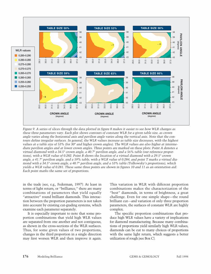
Constant Table Size. Figure 9 shows the “topogra-phy” of the WLR values in a series of slices throughsurfaces of constant table size. It provides data forvirtual diamonds with crown angles between 28.5°and 37.5°, and pavilion angles between 38° and 43°,at table sizes ranging from 50% to 66%. Overall,WLR is highest for fairly small tables (53% to 59%),and increases as crown angle decreases. Note theridge of higher WLR that trends from the lower leftcorner of each constant-table-size slice to the centerof the right side. This ridge becomes broader andshallower (smaller range of WLR values) as tablesize increases. It is evident that this complexity can-not be accounted for in a model of diamond propor-tions that treats the optimal set as the center of athree-dimensional “bull’s-eye” pattern, surroundedby concentric shells of worsening results.
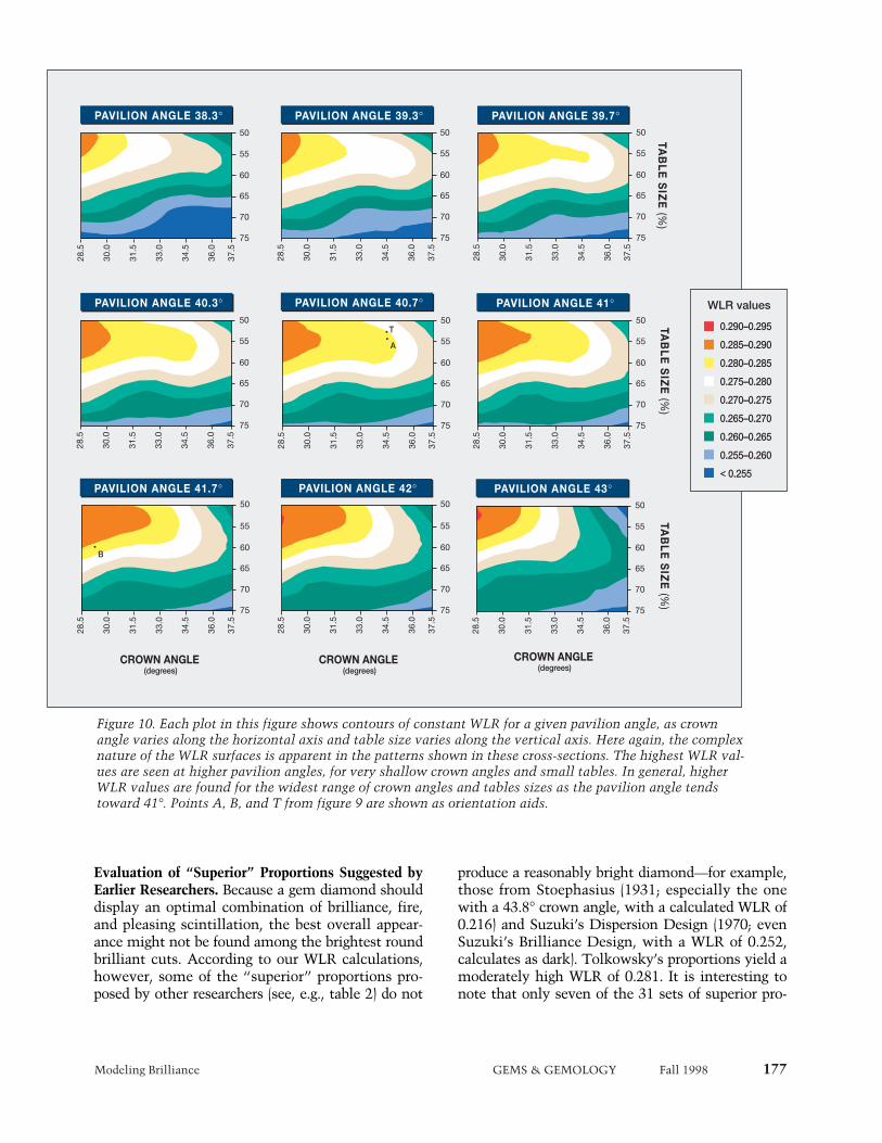
Constant Pavilion Angle. In figure 10, we showslices through the data at constant pavilion angle.The complex nature of the WLR surfaces is appar-ent from this view as well. The cross-section for a39.3° pavilion angle shows a pronounced ridge ofhigher WLR values starting in the upper left corner(shallow crowns and small tables), and trendingtoward higher crown angles at table sizes less than63%. This ridge is seen at all higher pavilion angles
as well; it is the same ridge seen at higher crownangles in figure 7, as viewed from many differentpavilion angles.
As the pavilion angle increases, the ridge definedby the WLR values seen in the orange, yellow, andwhite areas of figure 10 extends first to highercrown angles, and then broadens to include largertables. From this perspective, it is clear that pavil-ion angle can interact strongly with the other twoproportion parameters to produce similar WLR val-ues across broad ranges of crown angle and tablesize.
Constant Crown Angle. From the third perspective,constant crown angle (figure 11), the WLR contourslook much smoother. They form broad oval curvesat shallow crown angles, with oval maximumregions at crown angles between 30.5° and 36.5°,surrounded by relatively smooth contours ofdecreasing WLR.
For crown angles greater than 30°, the set of opti-mal parameters appears in this perspective as a“bull’s-eye” pattern, where a deviation in any direc-tion worsens the WLR. However, the pavilion andtable slices demonstrate that—in terms of WLR—there are many proportion combinations that yieldequally bright results.
0.280
0.275
0.270
0.265
0.260
50 55 60 65 70 75
TABLE SIZE (%)
WLR
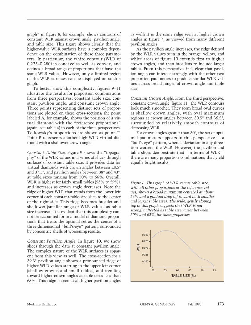
Figure 6. This graph of WLR versus table size,with all other proportions at the reference val-ues, shows a broad maximum centered at about56% and a gradual drop-off toward both smallerand larger table sizes. The wide, gently slopingtop of this graph suggests that WLR is notstrongly affected as table size varies between50% and 62%, for these properties.
174 Modeling Brilliance GEMS & GEMOLOGY Fall 1998
Influence of the Other Five Parameters on WLRResults. We explored the contribution to WLR ofthe remaining five proportion parameters—girdlethickness, number of girdle facets, culet size, lower-girdle length, and star length—by calculating WLRvalues while varying one parameter and holding theother seven (including crown angle, pavilion angle,and table size) constant at the reference proportionsin table 4. We found that WLR decreases slightly asthe thickness of the faceted girdle increases, pre-sumably because more light is lost through a thick-er girdle. In addition, WLR was approximately con-
stant as the number of girdle facets varied from 32to 144. A smaller WLR value was obtained for theextremely low value of 16 girdle facets.
We expected to see a steady decrease in WLRwith culet size, similar to that seen for girdle thick-ness; instead, we found relatively constant valuesfor culets as large as 12% (which would bedescribed as very large), and then a decrease as theculet size increased further. Although we have notyet examined this result in significant detail, itimplies that relatively few light rays escape throughthe culet.
Figure 7. This diagram showsthe variation in WLR withchanges in both crown angleand table size. The WLR val-ues are contoured, like atopographic map; each line isa constant WLR value.Regions with the highestWLR are shown in black,gray, and purple. High WLRvalues are found at crownangles up to 35°, beyondwhich WLR decreases rapid-ly. Note that the highestWLR values are seen at smalltable sizes. The shape of the0.280 WLR contour linereflects the variation in WLRdue to different crown angles;the local maxima at 23° and34° in figure 4 become“ridges” in this figure. Notealso the prominence of the“ridge” at the 23° crownangle; WLR remains high formuch larger tables than ateither larger or smaller crownangles. The digital imagesshow how the pattern of lightand dark can differ for pro-portions leading to similarWLR values. The virtual dia-mond on the left has a 23°crown angle and a 65% table(high WLR of 0.285), and theone on the right has a 34°crown angle and a 56% table(moderately high WLR of0.283); all other proportionsfor both virtual diamondswere held constant at the ref-erence proportions in table 4.
0.28
0.29
0.30
0.31
0.31
0.25
0.26
0.27
WLR
CO
NT
OU
RS
40
35
30
25
20
15
CR
OW
N A
NG
LE
(deg
rees)
50 55 60 65 70 75
TABLE SIZE (%)
0.310–0.315
0.305–0.310
0.300–0.305
0.295–0.300
0.290–0.295
0.285–0.290
0.280–0.285
0.275–0.280
0.270–0.275
0.265–0.270
0.260–0.265
0.255–0.260
0.250–0.255
0.245–0.250
WLR values
23° Crown angle65% Table size
WLR = 0.288
34° Crown angle56% Table size
WLR = 0.283

Modeling Brilliance GEMS & GEMOLOGY Fall 1998 175
The graph of WLR versus lower-girdle lengthshows a smooth curve with one maximum, similarto the curve seen in figure 5. With all other propor-tions at the reference values, we found the highestWLR when the lower-girdle length was 70%, ratherthan the commonly cut 75%. The total variation inWLR was small, and optimization of this parametershowed a strong dependence on star length.
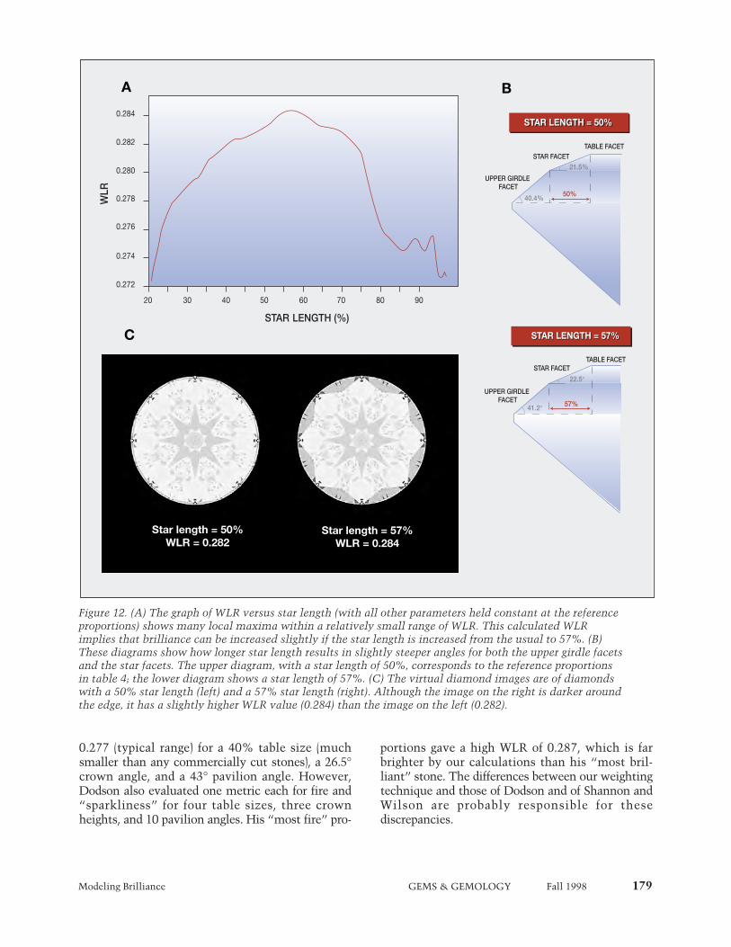
The graph of WLR versus star length shows sev-eral local maxima (figure 12A). The overall maxi-mum is found for a star length of 57%, rather thanthe 50% that is commonly cut for round brilliants.However, WLR varies by only 0.010—from 0.274(typical) to 0.284 (moderately high)—over the rangeof 25% to 95% star length. With the crown anglefixed at the reference value of 34°, the 57% starlength corresponds to a star facet angle of 22.5° andan upper-girdle-facet angle of 41.2° (WLR of 0.284),while the 50% star length yields a star facet angle of21.5° and an upper-girdle-facet angle of 40.4° (WLRof 0.282; see figure 12B). This change makes a rathersubtle difference in the profile of the diamond, pro-ducing a slightly steeper profile along these twofacets without any change in crown height.Although WLR varies only a little, indicating littlechange in brilliance, the pattern of light and darkacross the crown changes significantly, as shown inthe digital images (figure 12C).
DISCUSSIONVerification of the Model. To verify our study, weneed to ask whether our model adequately repro-duces both the visual appearance of white lightreturn from actual diamonds and the effects of cutthat are familiar from observation of actual dia-monds. The data indicate several similarities inappearance between the virtual diamonds generatedwith this model and actual stones. As we saw in fig-ure 5, the virtual diamond images showed charac-teristics of actual faceted diamonds (e.g., “fish-eye”and “nail head” appearances), as pavilion anglealone was changed. Similarly, we found a sharpdecrease in WLR for crown angles above 38°, andactual stones with such steep crown angles maylook darker (see, e.g., figure 1).
The most meaningful test of our mathematicalmodel is to compare the calculated WLR values tothe appearance of actual diamonds with those sameproportions. Figure 1 shows photos of actual dia-monds with proportions that correspond to varyingWLR values. As table 1 indicates, the stones in fig-
ure 1 have proportions that would fall in four of thefive general categories of WLR values: (1) high (cal-culated WLR greater than 0.285); (2) moderatelyhigh, which includes the proportion ranges of manyprofessed “superior” cuts (from Tolkowsky, Eppler,and Eulitz in table 2; WLR range of 0.280–0.285); (3)typical (WLR range of 0.270–0.280); and (4) low(WLR less than 0.265). However, because WLRmeasures light return from many different perspec-tives, not just one, no single photograph can demon-strate WLR results exactly.
Using WLR Data to Evaluate Brilliance. The WLRsurfaces that we have calculated as a function ofcrown angle, pavilion angle, and table size are irreg-ular, with a number of maxima, rather than a singlemaximum. These multiple “peaks” are a principalresult of this extensive three-dimensional analysis.Their existence supports a position taken by many
38
°39
°40
°41
°42
°43
°
70%
65%
60%
55%
50%
40° 39° 38° 37°34°
35°36°
33° 32° 31° 30°
Crown Angle
Table S
ize
Pavil
ion
Angl
e
Figure 8. The full complexity of the WLR sur-faces becomes apparent when we vary all threeparameters—crown angle, pavilion angle, andtable size. The contours show constant values ofWLR in increments of 0.005, from above 0.285for the orange area to below 0.250 for the darkblue area. The greatest complexity in the con-tours is seen at the highest WLR values. How-ever, since this three-dimensional projection isdrawn from only one perspective, it cannotshow all the variations in the WLR surfaces.
176 Modeling Brilliance GEMS & GEMOLOGY Fall 1998
in the trade (see, e.g., Federman, 1997): At least interms of light return, or “brilliance,” there are manycombinations of parameters that yield equally“attractive” round brilliant diamonds. This interac-tion between the proportion parameters is not takeninto account by existing cut-grading systems, whichexamine each parameter separately.
It is especially important to note that some pro-portion combinations that yield high WLR valuesare separated from one another and not contiguous,as shown in the cross-sections of the WLR surfaces.Thus, for some given values of two proportions,changes in the third proportion in a single directionmay first worsen WLR and then improve it again.
This variation in WLR with different proportioncombinations makes the characterization of the“best” diamonds, in terms of brightness, a greatchallenge. Even for one simple shape—the roundbrilliant cut—and variation of only three proportionparameters, the surfaces of constant WLR are highlycomplex.
The specific proportion combinations that pro-duce high WLR values have a variety of implicationsfor diamond manufacturing. Because many combina-tions of proportions yield similarly high WLR values,diamonds can be cut to many choices of proportionswith the same light return, which suggests a betterutilization of rough (see Box C).
TABLE SIZE 50%38
39
40
41
42
43
28.5
30.0
31.5
33.0
34.5
36.0
37.5
38
39
40
41
42
43
28.5
30.0
31.5
33.0
34.5
36.0
37.5
38
39
40
41
42
43
28.5
30.0
31.5
33.0
34.5
36.0
37.5
PA
VIL
ION
AN
GL
E (degrees)
TABLE SIZE 53% TABLE SIZE 56%
38
39
40
41
42
43
28.5
30.0
31.5
33.0
34.5
36.0
37.5
TABLE SIZE 59%38
39
40
41
42
43
28.5
30.0
31.5
33.0
34.5
36.0
37.5
TABLE SIZE 63%38
39
40
41
42
43
28.5
30.0
31.5
33.0
34.5
36.0
37.5
TABLE SIZE 66%
PAVILION
AN
GLE
(degrees)
CROWN ANGLE (degrees)
CROWN ANGLE (degrees)
CROWN ANGLE (degrees)
0.285–0.290
0.280–0.285
0.275–0.280
0.270–0.275
0.265–0.270
0.260–0.265
0.255–0.260
0.250–0.255
WLR values
T
B
A
Figure 9. A series of slices through the data plotted in figure 8 makes it easier to see how WLR changes asthese three parameters vary. Each plot shows contours of constant WLR for a given table size, as crownangle varies along the horizontal axis and pavilion angle varies along the vertical axis. Note that the con-tours define irregular surfaces. In general, the WLR values increase as table size decreases, with the highestvalues at a table size of 53% (for 30° and higher crown angles). The WLR values are also higher at interme-diate pavilion angles and at lower crown angles. Three points are marked on these plots: Point A denotes avirtual diamond with a 34.5° crown angle, a 40.7° pavilion angle, and a 56% table (our reference propor-tions), with a WLR value of 0.282. Point B shows the location of a virtual diamond with a 29.5° crownangle, a 41.7° pavilion angle, and a 59% table, with a WLR value of 0.284, and point T marks a virtual dia-mond with a 34.5° crown angle, a 40.7° pavilion angle, and a 53% table (Tolkowsky’s proportions), whichyields a WLR value of 0.281. These same three points are shown in figures 10 and 11 as an orientation aid:Each point marks the same set of proportions.
Modeling Brilliance GEMS & GEMOLOGY Fall 1998 177
PAVILION ANGLE 38.3°
TAB
LE
SIZ
E (%
)
CROWN ANGLE (degrees)
CROWN ANGLE (degrees)
CROWN ANGLE (degrees)
TAB
LE
SIZ
E (%
)TA
BL
E S
IZE
(%)
PAVILION ANGLE 39.3° PAVILION ANGLE 39.7°
PAVILION ANGLE 40.3° PAVILION ANGLE 40.7° PAVILION ANGLE 41°
PAVILION ANGLE 41.7° PAVILION ANGLE 42° PAVILION ANGLE 43°50
55
60
65
70
75
28.5
30.0
31.5
33.0
34.5
36.0
37.5
50
55
60
65
70
75
28.5
30.0
31.5
33.0
34.5
36.0
37.5
50
55
60
65
70
75
28.5
30.0
31.5
33.0
34.5
36.0
37.5
50
55
60
65
70
75
28.5
30.0
31.5
33.0
34.5
36.0
37.5
50
55
60
65
70
75
28.5
30.0
31.5
33.0
34.5
36.0
37.5
50
55
60
65
70
75
28.5
30.0
31.5
33.0
34.5
36.0
37.5
50
55
60
65
70
75
28.5
30.0
31.5
33.0
34.5
36.0
37.5
50
55
60
65
70
75
28.5
30.0
31.5
33.0
34.5
36.0
37.5
50
55
60
65
70
75
28.5
30.0
31.5
33.0
34.5
36.0
37.5
0.290–0.295
0.285–0.290
0.280–0.285
0.275–0.280
0.270–0.275
0.265–0.270
0.260–0.265
0.255–0.260
< 0.255
WLR values
T
B
A
Figure 10. Each plot in this figure shows contours of constant WLR for a given pavilion angle, as crownangle varies along the horizontal axis and table size varies along the vertical axis. Here again, the complexnature of the WLR surfaces is apparent in the patterns shown in these cross-sections. The highest WLR val-ues are seen at higher pavilion angles, for very shallow crown angles and small tables. In general, higherWLR values are found for the widest range of crown angles and tables sizes as the pavilion angle tendstoward 41°. Points A, B, and T from figure 9 are shown as orientation aids.
Evaluation of “Superior” Proportions Suggested byEarlier Researchers. Because a gem diamond shoulddisplay an optimal combination of brilliance, fire,and pleasing scintillation, the best overall appear-ance might not be found among the brightest roundbrilliant cuts. According to our WLR calculations,however, some of the “superior” proportions pro-posed by other researchers (see, e.g., table 2) do not
produce a reasonably bright diamond—for example,those from Stoephasius (1931; especially the onewith a 43.8° crown angle, with a calculated WLR of0.216) and Suzuki’s Dispersion Design (1970; evenSuzuki’s Brilliance Design, with a WLR of 0.252,calculates as dark). Tolkowsky’s proportions yield amoderately high WLR of 0.281. It is interesting tonote that only seven of the 31 sets of superior pro-
178 Modeling Brilliance GEMS & GEMOLOGY Fall 1998
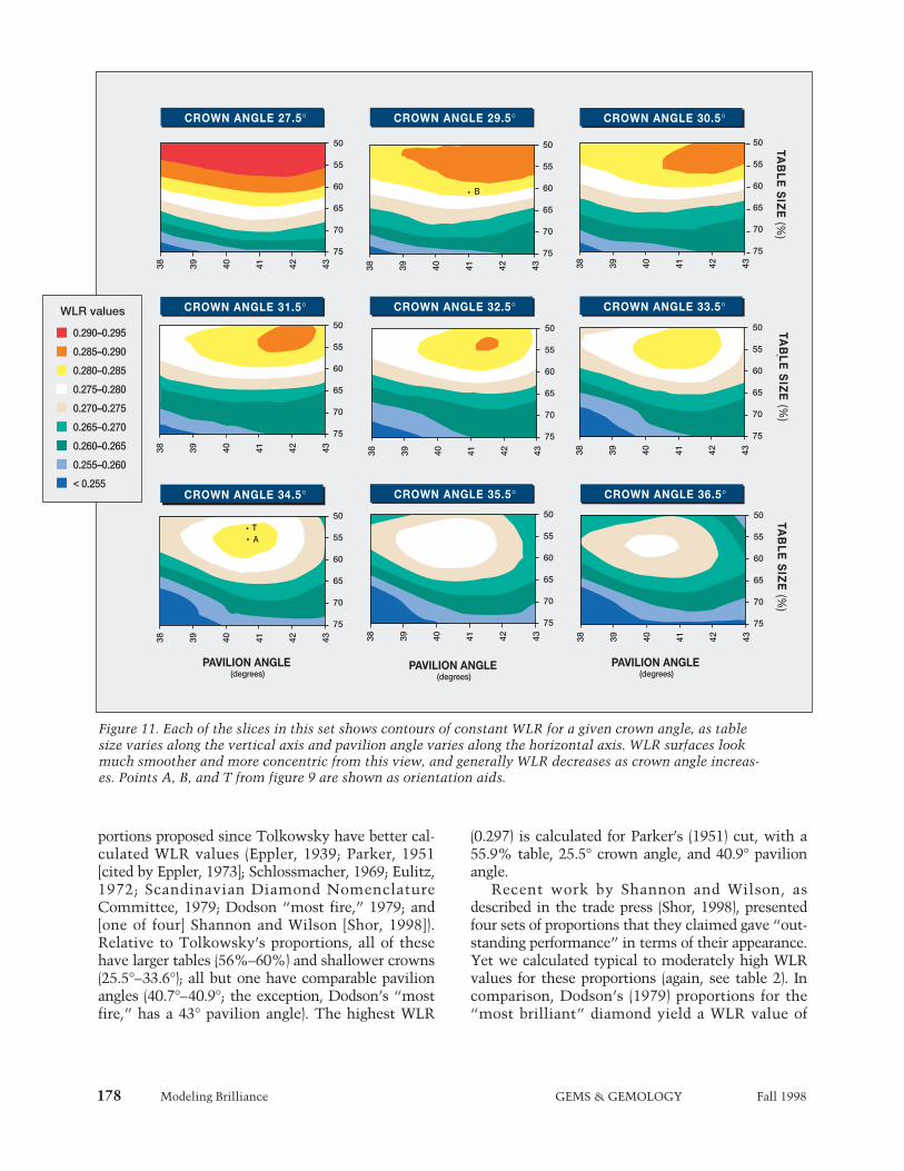
portions proposed since Tolkowsky have better cal-culated WLR values (Eppler, 1939; Parker, 1951[cited by Eppler, 1973]; Schlossmacher, 1969; Eulitz,1972; Scandinavian Diamond NomenclatureCommittee, 1979; Dodson “most fire,” 1979; and[one of four] Shannon and Wilson [Shor, 1998]).Relative to Tolkowsky’s proportions, all of thesehave larger tables (56%–60%) and shallower crowns(25.5°–33.6°); all but one have comparable pavilionangles (40.7°–40.9°; the exception, Dodson’s “mostfire,” has a 43° pavilion angle). The highest WLR
(0.297) is calculated for Parker’s (1951) cut, with a55.9% table, 25.5° crown angle, and 40.9° pavilionangle.
Recent work by Shannon and Wilson, asdescribed in the trade press (Shor, 1998), presentedfour sets of proportions that they claimed gave “out-standing performance” in terms of their appearance.Yet we calculated typical to moderately high WLRvalues for these proportions (again, see table 2). Incomparison, Dodson’s (1979) proportions for the“most brilliant” diamond yield a WLR value of
PAVILION ANGLE (degrees)
PAVILION ANGLE (degrees)
PAVILION ANGLE (degrees)
CROWN ANGLE 27.5°TA
BL
E S
IZE
(%)
TAB
LE
SIZ
E (%
)TA
BL
E S
IZE
(%)
CROWN ANGLE 29.5° CROWN ANGLE 30.5°
CROWN ANGLE 31.5° CROWN ANGLE 32.5° CROWN ANGLE 33.5°
CROWN ANGLE 34.5° CROWN ANGLE 35.5° CROWN ANGLE 36.5°
50
55
60
65
70
75
38 39 40 41 42 43
50
55
60
65
70
75
38 39 40 41 42 43
50
55
60
65
70
75
38 39 40 41 42 43
50
55
60
65
70
75
38 39 40 41 42 43
50
55
60
65
70
75
38 39 40 41 42 43
50
55
60
65
70
75
38 39 40 41 42 43
50
55
60
65
70
75
38 39 40 41 42 4350
55
60
65
70
75
38 39 40 41 42 43
50
55
60
65
70
75
38 39 40 41 42 43
0.290–0.295
0.285–0.290
0.280–0.285
0.275–0.280
0.270–0.275
0.265–0.270
0.260–0.265
0.255–0.260
< 0.255
WLR values
TA
B
Figure 11. Each of the slices in this set shows contours of constant WLR for a given crown angle, as tablesize varies along the vertical axis and pavilion angle varies along the horizontal axis. WLR surfaces lookmuch smoother and more concentric from this view, and generally WLR decreases as crown angle increas-es. Points A, B, and T from figure 9 are shown as orientation aids.
0.277 (typical range) for a 40% table size (muchsmaller than any commercially cut stones), a 26.5°crown angle, and a 43° pavilion angle. However,Dodson also evaluated one metric each for fire and“sparkliness” for four table sizes, three crownheights, and 10 pavilion angles. His “most fire” pro-
portions gave a high WLR of 0.287, which is farbrighter by our calculations than his “most bril-liant” stone. The differences between our weightingtechnique and those of Dodson and of Shannon andWilson are probably responsible for thesediscrepancies.
Figure 12. (A) The graph of WLR versus star length (with all other parameters held constant at the referenceproportions) shows many local maxima within a relatively small range of WLR. This calculated WLRimplies that brilliance can be increased slightly if the star length is increased from the usual to 57%. (B)These diagrams show how longer star length results in slightly steeper angles for both the upper girdle facetsand the star facets. The upper diagram, with a star length of 50%, corresponds to the reference proportionsin table 4; the lower diagram shows a star length of 57%. (C) The virtual diamond images are of diamondswith a 50% star length (left) and a 57% star length (right). Although the image on the right is darker aroundthe edge, it has a slightly higher WLR value (0.284) than the image on the left (0.282).
Modeling Brilliance GEMS & GEMOLOGY Fall 1998 179
0.284
0.282
0.280
0.278
0.276
0.274
0.272
WLR
20 30 40 50 60 70 80 90
STAR LENGTH (%)
STAR LENGTH = 57%STAR LENGTH = 57%
STAR LENGTH = 50%STAR LENGTH = 50%
TABLE FACET
22.5°
41.2°
21.5%
40.4%
57%
50%
STAR FACET
TABLE FACET
UPPER GIRDLE FACET
UPPER GIRDLE FACET
STAR FACET
A B
C
Star length = 50%WLR = 0.282
Star length = 57%WLR = 0.284

180 Modeling Brilliance GEMS & GEMOLOGY Fall 1998
Implications for Existing Cut-Grading Systems. Ourresults disagree with the concepts on which the pro-portion grading systems currently in use by variouslaboratories appear to be based. In particular, theydo not support the idea that all deviations from anarrow range of crown angles and table sizes shouldbe given a lower grade. We have calculated theWLR values for the proportion ranges of each grad-ing system in table 3. The highest grades for most ofthose systems yield WLR values from 0.275 to0.284 (typical to moderately high). Clearly, these areattractive stones. However, the maximum WLRachievable increases as the grade worsens in thesesystems.
For example, diamonds with a 31° to 32° crownangle, a 41° to 41.4° pavilion angle, and a table sizebetween 53% and 57% have WLR values of0.284–0.285 (moderately high). Although their WLRvalues are slightly higher than those of the topgrades in table 3, these round brilliants wouldreceive lower cut grades in most systems because ofthe lower crown angle. Similarly, diamonds withcrown angles between 31° and 33°, pavilion anglesof 42°, and tables between 53% and 59% yield cal-culated WLR values from 0.281 to 0.286 (moderate-ly high to high). These values may exceed those ofdiamonds that currently receive the best grades, butsuch stones earn medium to low grades from theexisting systems because of the larger pavilionangle. Last, round brilliants with larger tables (61%to 63%) are much more common than those withsmall tables (again, see Box B). Such diamonds canshow moderately high WLR values when combinedwith crown angles between 30° and 33°, and pavil-ion angles from 40° to 42°, but diamonds with largetables are penalized heavily in most of the existingcut grading systems, regardless of their brightness.
Although arguments can be made for downgrad-ing diamonds with lower crown angles or largertables (on the basis, for example, that they do notyield enough fire), there is little documented evi-dence at present to support—or refute—suchclaims. However, at least according to Dodson(1979), both fire and scintillation depend on combi-nations of proportions, rather than on any singleparameter.
Although our results for brilliance do not sup-port current cut grading systems, we do not expectthem to surprise most diamond manufacturers. GIAGTL has seen significant numbers of diamonds thatare cut to various proportion combinations that
would correspond to moderately high to high WLRvalues. The results of this study support the empiri-cal understanding that cutters have of the relation-ships between proportions and brilliance.
FUTURE DIRECTIONS
The model presented here can be used readily toexplore many aspects of how diamond cut affectsappearance. The greatest challenge in this researchis the derivation of metrics for appearance concepts,including selection of the best lighting and observa-tion conditions for each metric. Currently, we areexploring metrics for fire, which has many possiblevariables, such as: the size, extent, placement, andexit angle of colored light rays; the distribution ofcolors observed; and how the observation and light-ing geometries govern the recombination of coloredlight rays into white light. We plan to devise a met-ric for scintillation as well, and to compare theseresults over the same proportion ranges to the met-rics for brilliance and fire. We also intend to exploreother lighting conditions, as we develop metrics forthe other appearance concepts.
In addition, we plan to explore two importantconsiderations that have been neglected thus far:symmetry and color. From our efforts and observa-tions of actual diamonds for this study, we suspectthat symmetry deviations may produce significantvariation in brilliance (this was also suggested by A.Gilbertson, pers. comm., 1998). Incorporation ofsymmetry deviations requires adding more parame-ters to describe the shape of the round brilliant, anddevising a method of tracking multiple symmetryfaults. Once this is done, the model can be used tocalculate both images and metric values that showhow symmetry deviations, both singly and in com-bination, change diamond appearance.
Incorporating color, whether letter grades (e.g.,from J to Z) or fancy colors, requires giving the vir-tual diamond a set of dimensions, applying a specif-ic absorption spectrum, and specifying the color dis-tribution (even or zoned). Then the model can keeptrack of the energy a ray loses by absorption (inaddition to leakage) as it travels through the virtualdiamond. Fluorescence effects can be included bysimilar techniques (applying a fluorescence spec-trum), and the claim that fluorescent diamondslook better at different proportions than those thatare inert (G. Tolkowsky, 1996) can be directly eval-uated.
This model can also be used to explore the many

Modeling Brilliance GEMS & GEMOLOGY Fall 1998 181
Fully symmetrical octahedral rough lends itself quitenicely to the higher crown and smaller table typical ofthe “Ideal” cut, as shown in figure C-1. However, sev-eral diamond manufacturers have estimated that onlyabout one fourth of the rough they cut is fully sym-metrical. (A. D. Klein, pers. comm., 1998). Other roughshows some irregularity in shape: shorter along onepoint-to-point distance than the other two; one ormore flattened edges with minor development of cubeor dodecahedral faces; or some relative tilt or twistbetween the two pyramids that comprise the octahe-dron. These variations in the shape of the rough can beaccommodated during cutting either by accepting alower weight yield or by modifying the cutting propor-tions.
If we consider a typical slightly asymmetric octa-hedron (see, e.g., figure C-2), one could still worktoward an “Ideal” cut despite the limitations of therough. Choosing to saw such a piece just slightly offcenter separates the top from the bottom of the octahe-dron, yielding two symmetrical square pyramids; forthe purposes of this example, let us assume that thelarger of these two pieces weighs about 1.75 ct. Aimingfor a crown height of 16% or 17% (which allows for acrown angle of 34°–35°, at a range of table sizes) pushesthe girdle down below the widest part of the rough,forcing a lower yield. After exploring the possibilitiesfor this example with a DiaExpert system (see, e.g.,Caspi, 1997), the best yield we found for top-graded
proportions as defined by most of the cut-grading sys-tems (see table 3), was 0.93 ct, with a 35.5° crownangle, a 40.8° pavilion angle, and a 57% table, giving acalculated WLR value of 0.279.
However, the shape of this rough suggests a differ-ent sawing position; it promotes cutting a shallowercrown and a larger table. From the same sawn bottompiece of about 1.75 ct, one could plan a round brilliantwith a 60% table and about a 60% total depth, with a32.7° crown angle and a 41.5° pavilion angle, whichwould achieve a calculated WLR value of 0.279 and afinal weight of 1.02 ct. In this example, striving for ahigh cut grade (table 3) results in a substantially lowerweight yield while achieving the same brightness, asexpressed by WLR.
There is broad agreement throughout the diamondtrade that cutting a diamond for maximum weightyield without consideration of the final appearanceconstitutes unacceptably poor manufacturing.Nevertheless, the disagreement over which propor-tions yield the best-looking diamonds fuels the debateas to how to maximize both weight yield and appear-ance. Although brilliance is only one aspect of overalldiamond appearance, our results indicate that for thesame piece of rough, it is possible to attain greateryield with the same WLR.
BOX C: AN EXAMPLE ILLUSTRATING CUTTING CHOICESBOX C: AN EXAMPLE ILLUSTRATING CUTTING CHOICES
Figure C-1. Starting with a rough diamond thatis a highly symmetric octahedron, one can man-ufacture a stone with the high crown typical ofthe “Ideal” and obtain a good yield.
Figure C-2. Other sets of proportions, particularlyslightly lower crown angles, often give the bestyield from commonly encountered asymmetricoctahedral diamond rough, with equivalent bright-ness. This yield can be significantly lower whensuch rough is fashioned to “Ideal” proportions.
182 Modeling Brilliance GEMS & GEMOLOGY Fall 1998
ways that faceted shape and proportions affect theface-up appearance of fancy-colored diamonds. Inaddition, we hope to address the effects that differ-ent kinds of inclusions can have on the paths oflight rays in a diamond (e.g., reflection from the sur-face of a “feather,” or scattering from a cloud of pin-points), and the additional light loss that resultsfrom poor surface finish.
CONCLUSION
In this first report of the results of our research oncut proportions, we have presented a mathematicalmodel of the round brilliant diamond that describesthis shape in terms of eight proportion parameters. Italso incorporates the physical factors that affect howlight interacts with a faceted diamond. At present,the “virtual” diamonds we have examined are allcolorless, flawless round brilliants with mathemati-cally perfect symmetry and polish; they vary only intheir proportions. We created digital images of someof these virtual diamonds that reproduce the keyfeatures of actual diamonds (again, see figures 2, 4,5, 7, and 12).
In this report, we have focused on brilliance,which was considered the main factor of diamondappearance in most previous analyses of the roundbrilliant diamond—from Tolkowsky in 1919 toShannon and Wilson in 1998. We have quantifiedbrilliance on the basis of weighted light return(WLR). After calculating WLR values for more than20,000 proportion combinations, we found that therelationship between brilliance and the three prima-ry proportion parameters (crown angle, pavilionangle, and table size) is complex, and that there area number of proportion combinations that yieldhigh WLR values. We also discovered that there aresome commercial proportion combinations thatproduce rather low WLR values (again, see figure 1and Box B). Comparisons to actual diamonds sup-port our premise that WLR captures the essence ofbrilliance.
Our model differs from its predecessors in one ormore of three ways: (1) it is three-dimensional; (2) ituses the most detailed existing data on the proper-ties of a colorless diamond; and (3) it uses an aver-aged observer condition that takes into account thelikeliest ways in which a diamond dealer or con-sumer looks at the stone. (The last is unique to thismodel.) Nevertheless, we do not consider the WLRmetric we have devised to be the whole story withregard to diamond appearance.
Brilliance is only one part of the puzzle; fire andscintillation, and probably symmetry deviations andcolor, will also have to be analyzed before theeffects of cutting on diamond appearance can befully understood. Yet, no fashioned diamond can beconsidered beautiful if it lacks brilliance. We caninfer from the WLR data that certain combinationsof proportions will produce low light return. This isimportant since a round brilliant that is severelydeficient in any one appearance aspect cannot beconsidered well cut, even if it performs well foranother aspect. For example, these WLR resultscould be used to define proportions for which around brilliant diamond will appear too dark; noamount of fire or pleasing scintillation would bal-ance such darkness to produce beauty.
Ultimately, we hope to use this model to findthe various ranges of proportions that clearly fail tobring out the attractive qualities of a round brilliantdiamond for each appearance aspect (brilliance, fire,and scintillation). The proportion ranges thatremain can be examined for balances between thedifferent appearance aspects, and an intelligent, fact-based discussion can take place regarding whichproportions produce diamonds of superior appear-ance. It is our opinion that any cut grading assess-ment devised in the absence of this broader pictureis premature.
Acknowledgments: Several people provided stimulat-ing discussions and a broader perspective: GlennNord and GIA colleagues Bill Boyajian, Brook Ellis,Richard T. Liddicoat, Vince Manson, Tom Moses,and Tom Yonelunas, as well as GIA GTL researchersPeter DeJong, Ronnie Geurts, and Marc Verboven.Dona Dirlam and the staff of the Richard T.Liddicoat Gemological Library and InformationCenter assisted with literature searches. HimikoNaka (GIA GTL) and Ronnie Geurts translated arti-cles published in Japanese and German, respectively.Sheryl Cashmore, Kim Cino, Alan DeGhionno, andJulie Lahman of GIA GTL located examples of actualdiamonds of various proportions, and Richard VonSternberg of EightStar Diamond Company, SantaRosa, California, provided a diamond that approxi-mated the symmetry of the model. A number of dia-mond manufacturers spoke with us about the vari-ables involved in creating a polished round brilliantfrom diamond rough; we especially thank those atJulius Klein, Inc., New York.
Modeling Brilliance GEMS & GEMOLOGY Fall 1998 183
REFERENCESAstric B., Merigoux H., Zecchini P. (1992) Etude de la variation
de l’aspect de pierres taillées à l’aide d’images de synthèse. LaGemmologia, Vol. 17, No. 1, pp. 7–31.
Bergheimer H. (1938) Die Schleifrichtungen auf den Facetten desDiamantbrillanten. Neues Jahrbuch für Mineralogie, Geo-logie, und Paläontologie, Vol. 75A, pp. 145–158.
Caspi A. (1997) Modern diamond cutting and polishing. Gems &Gemology, Vol. 33, No. 2, pp. 102–121.
Connellan M., Pozzibon L. (1984) The Australian ideal design forround brilliants. Australian Gemmologist, Vol. 24, pp.219–226, 243–246.
Crowningshield G.R., Moses T. (1997) Diamond: Damaged fromwear. Gem Trade Lab Notes, Gems & Gemology, Vol. 33,No. 1, pp. 55–56.
Dodson J.S. (1979) The statistical brilliance, sparkliness and fireof the round brilliant-cut diamond. Diamond Research, pp.13–17.
Elbe M.G. (1972) Erstaunliche Schmuckeffekte an Brillanten.Zeitschrift der Deutschen Gemmologischen Gesellschaft,Vol. 21, No. 4, pp. 189–212.
Eppler W.F. (1933) Der Diamant und seine Bearbeitung.Wilhelm Diebener GmbH, Leipzig, 68 pp.
Eppler W.F. (1938) Die Ideal-Schleifformen durchsichtigerEdelsteine. Zentralblatt für Mineralogie, Geologie, undPaläontologie, Abteilung A, pp. 1–5.
Eppler W.F. (1939) Die Brillanz durchsichtiger Edelsteine.Fortschritte der Mineralogie, Kristallographie, undPetrographie, Vol. 23, pp. 1–40.
Eppler W.F. (1940) Beitrag zum Brillanzproblem II. Zentralblattfür Mineralogie, Geologie, und Paläontologie, Abteilung A,No. 4, pp. 93–96.
Eppler W.F. (1973) Praktische Gemmologie. Rühle-DiebenerVerlag KG, Stuttgart.
Eppler W.F., Klüppelberg E. (1940) Die praktische Brillantschliffdes Diamanten. Neues Jahrbuch für Mineralogie, Geologie,und Paläontologie, Vol. 75A, pp. 135–144.
Eulitz W.R. (1972) Die rechnerische Ermittlung der optimalenBrillanz der Brillanten. Zeitschrift der DeutschenGemmologischen Gesellschaft, Vol. 21, No. 1, pp. 13–43.
Federman D. (1997) Make believe. Modern Jeweler, Vol. 96, No.9, pp. 23–38, 62–63.
Foley J.D., Ed. (1996) Computer Graphics: Principles andPractice, 2nd ed. in C, Addison-Wesley Publishing Co.,Reading, MA.
GIA Diamond Dictionary, 3rd ed. (1993) Gemological Instituteof America, Santa Monica, CA, 275 pp.
GIA Jeweler’s Manual (1989) Gemological Institute of America,Santa Monica, CA, 327 pp.
Gilbertson A. (1998) Letting Light Speak for Itself. DiamondProfile Inc., Portland, Oregon, 14 pp. plus appendices.
Gilbertson A., Walters C. (1997) The measure of beauty.Rapaport Diamond Report, Vol. 20, No. 6, pp. 43, 45–46.
Johnsen A. (1926) Form und Brillanz der Brillanten.Sitzungsberichte der Preussischen Akademie derWissenschaften, Physikalische-Mathematische Klasse, Vol.23, pp. 322–330.
Lawrence J. (1998) Just how much sparkle? Diamond
International, No. 53, pp. 77–78.Maier W. (1936) Brillanz geschliffener Edelsteine. Neues
Jahrbuch für Mineralogie, Geologie, und Paläontologie, Vol.71A, pp. 458–491.
Maier W. (1938) Vollreflexbrillanten. Zentralblatt fürMineralogie, Geologie, und Paläontologie, Abteilung A, pp.230–239.
Nassau K. (1983) The Physics and Chemistry of Color—TheFifteen Causes of Color. Wiley Interscience, New York, 454pp.
Nestlebaum K. (1996) New AGS lab stakes its claim on cutgrade. Rapaport Diamond Report, Vol. 19, No. 17, pp. 15–17.
Nestlebaum K. (1997) Ideals: Worth the trouble to those who cutthem. Rapaport Diamond Report, Vol. 20, No. 10, pp. 18–19.
Papadopoulos A.D, Anastassakis E. (1991) Optical properties ofdiamond. Physical Review B, Vol. 43, No. 6, pp. 5090–5097.
Rösch S. (1926) Die Brillanzwirkung des geschliffenenDiamanten. Deutsche Goldschmiede Zeitung, No. 5, pp.45–48; No. 7, pp. 65–67; No. 9, pp. 88–90.
Rösch S. (1927) Beitrag zum Brillanzproblem IV. Zeitschrift fürKristallographie, Vol. 65, pp. 46–68.
Scandinavian Diamond Nomenclature Committee (1979) TheScandinavian Diamond Nomenclature and GradingStandards: Official Version. Trade Associations of Jewellersin Denmark, Finland, Norway and Sweden, 50 pp.
Schlossmacher K. (1969) Edelsteine und Perlen, 5 Auflage. E.Schweizerbart’sche Verlagsbuchhandlung, Stuttgart.
Shor R. (1993) Cutting grades—new complications. Jewelers’Circular-Keystone, Vol. 164, No. 4, pp. 52–55.
Shor R. (1997) Consumers who care about cut: A small, butgrowing group. Jewelers’ Circular-Keystone, Vol. 168, No. 6,pp. 124–126.
Shor R. (1998) Computer engineers create proportion grade pro-gram. New York Diamonds, Vol. 44, pp. 26–28.
Stoephasius A. (1931) Lässt sich das Gewicht gefasster Brillantensicher berechnen? Deutsche Goldschmiede Zeitung, No. 45,pp. 470–474.
Suzuki S. (1970) A new design for brilliance plus dispersion.Australian Gemmologist, Vol. 10, No. 10, pp. 13–24.
Tillander H. (1966) Six centuries of diamond design. Gems &Gemology, Vol. 12, No. 3, pp. 77–95.
Tillander H. (1995) Diamond Cuts in Historical Jewellery:1381–1910. Art Books International, London.
Tognoni C. (1990) An automatic procedure for computing theoptimum cut proportions of gems. La Gemmologia, Vol. 25,No. 3–4, pp. 23–32.
Tolkowsky G. (1996) Cutting the Edges. Diamond Insight, Vol.9, No. 2, pp. 9–10.
Tolkowsky M. (1919) Diamond Design: A Study of theReflection and Refraction of Light in a Diamond. E. & F.N.Spon, London.
Wade F.B. (1916) Diamonds: A Study of the Factors that GovernTheir Value. G.P. Putnam’s Sons, New York.
Ware, J.W. (1936) New diamond cuts break more easily. Gems &Gemology, Vol. 2, No. 4, p. 68.
Watermeyer B. (1991) Diamond Cutting, 4th ed. PreskorDoornfontein, Johannesburg, 406 pp.
Wright, W.D. (1969) The Measurement of Colour, 4th ed., VanNostrand, New York.