Embed Size (px)
Citation preview

0 | P a g e
Lower Fraser Valley British Columbia, Chilliwack to
Surrey Interurban
Proposal for Rail for the Valley
1010/LWP/RFTV/062010 - 02 June 2010
by David Cockle
LEEWOOD PROJECTS
Planning Project Solutions
38, Deacon Road, Kingston-upon-Thames. Surrey. KT2 6LU, UK Phone: +44 (0)20 8541 0715 Mobile +44 (0)7702 720766 Fax: +44 (0)20 8546 4260 E-Mail [email protected] www.leewoodprojects.co.uk

1 | P a g e

2 | P a g e
Lower Fraser Valley British Columbia, Chilliwack to Scott Road, Surrey
Interurban - Community Rail
Table of Contents
1.0 Executive Summary 5
2.0 Introduction 5 3.0 Background 7 4.0 Benefits of Interurban & Community rail strategy 8 5.0 Assessment of existing infrastructure 9
6.0 Stage 1.0 (Initial scheme) 15 6.1 Phase 1 proposal: Chilliwack to Scott Road – Diesel Light Rail upgrade 6.2 Phase 2 proposal: Chilliwack to Scott Road – Electrification upgrade
7.0 Proposed Rail Stations, land use and employment opportunities 16 7.1 Railway Stations 7.2 Tram stops
8.0 Accessibility improvements for rail stations 20 8.1 Automobile Access & Parking 8.2 Pedestrian & Mobility Impaired Access 8.3 Feeder & Shuttle Bus Connections 8.4 Cycling Facilities (Carriage of Cycles)
9.0 Depot, Maintenance & Control centre 22 10.0 Infrastructure - Civil Engineering 24 10.1 Drainage 10.2 Earthworks/embankment stability
10.3 Bridges & culverts
11.0 Infrastructure - Permanent Way 25 11.1 Track [ROW] design & upgrade
11.2 Double track 11.3 Passing loops
12.0 Infrastructure – Signalling 30 12.1 Operational running proposals – Time separation 12.2 Signalling control proposal
13.0 Infrastructure – Communications 32 14.0 Infrastructure – Electrification 32
3 | P a g e
15.0 Utility diversions 33 16.0 Highways 33
16.1 Traffic assessment at key at-grade Railway Crossings 16.2 At-grade Railway / Road Crossings, appraisal and proposals 16.3 Reference - Vehicle/Pedestrian Rail Crossings in Other Cities-Calgary
17.0 Light Rail Vehicle (LRV) options 37
17.1 Tram-Train 17.1.1 Diesel 17.1.2 Electric 17.1.3 Diesel/Electric hybrid 17.2 Tram/LRV 17.3 Diesel-Electric Multiple Unit [DEMU] 17.4 Electric Multiple Unit [EMU] 17.5 Electricity generator trailers 17.6 2
nd use/reconditioned LRV’s
18.0 Operating criteria’s & options 48 18.1 Headway & Frequency
18.2 Ticketing 18.3 Heritage Tramcar Operations
19.0 Capital and operating costs of Interurban/Community rail service 50 19.1 Exclusions
19.2 Stage 1.0; Phase 1 Capital budget 19.3 Stage 1.0; Phase 2 Capital budget
19.4 Stage 1.0; Capital cost per Km
20.0 Stage 2.0 (Further extension proposal) 51 20.1 Phase 2a proposal: Scott Road to Richmond – at grade 20.2 Phase 2b proposal: Richmond to Vancouver Central station – at grade 20.3 Phase 3 proposal: Chilliwack station to Rosedale
21.0 Safety considerations for Interurban/Community rail project 52 21.1 Rail vehicle safety assessments 21.2 Vehicular/pedestrian rail crossings
22.0 Conclusions and Recommendations 53 22.1 Conclusions 22.2 Recommendations
Notes & Acknowledgements 54 List of Appendices 55 Appendix A Figure/Photograph references and acknowledgments Appendix B Maps of proposed Interurban Appendix C the Case for Light Rail Appendix D - Proposed Interurban/Community vehicle references - Diesel Trams? A New Way forward Appendix E Train-Trams, Zwickau, Riverline & Seetalbahn Appendix F Electric Traction Beyond the Wires Appendix G Proposed Interurban/Community Rail Station layouts Appendix H Background & Report References

4 | P a g e
List of Tables 73 Table 1: Proposed Interurban/Community Rail travel time matrix Table 2: Schedule of bridge structures Table 3: Schedule of grade highway crossings
© Leewood Projects Ltd 2010
Leewood Projects Ltd, the author and all of the authors listed in the acknowledgements,
notes and references are the owners or the licensees of the intellectual property rights in
this report, and in the material contained in it. Those works are protected by copyright laws
and treaties around the world. All such rights are reserved
Date June 2010 Document Ref No:
1010/LWP/RFTV/062010
This document is uncontrolled from
time of printing Reference: DAC
Revision 02
5 | P a g e
1.0 Executive Summary
This report details, the line of the old BCER Lower Fraser Valley Interurban, an overall distance of 98 km from the Fraser River and Surrey to Chilliwack. The report proposes the upgrade of the existing railway line and the early reintroduction of an 80 – 120 Kph service between Chilliwack and Scott‟s Road in Surrey. (Stage 1.0) The proposed Chilliwack to Surrey Light rail/Interurban will share the right-of-way with the existing freight operations of CP Rail, CNR and the Southern Railway of BC, a `Short line‟ railway under a mixed fleet operation, track sharing agreement. The Stage 1.0, Phase 1 interim option proposes, a diesel Light Rail/Interurban metro service, with two/three car articulated diesel electric [DEMU] Interurban multiple unit train-sets, 32 to 45 metres long, operating a minimum twenty minute service, in both directions in the morning & evening peaks – Monday to Saturday (06:00 to 22:00) and minimum half hourly, each way service, off-peak and on Sundays. The proposed rail vehicles would be 75 to 100% low floor, providing mobility impaired access, with a capacity of 120 to 240 passengers. The Stage 1.0, Phase 2 option, proposes a future overhead electrification upgrade. Stage 2.0 proposes further extensions, from Surrey across the Fraser River to Richmond, Burnaby, Vancouver and east from Chilliwack to Rosedale.
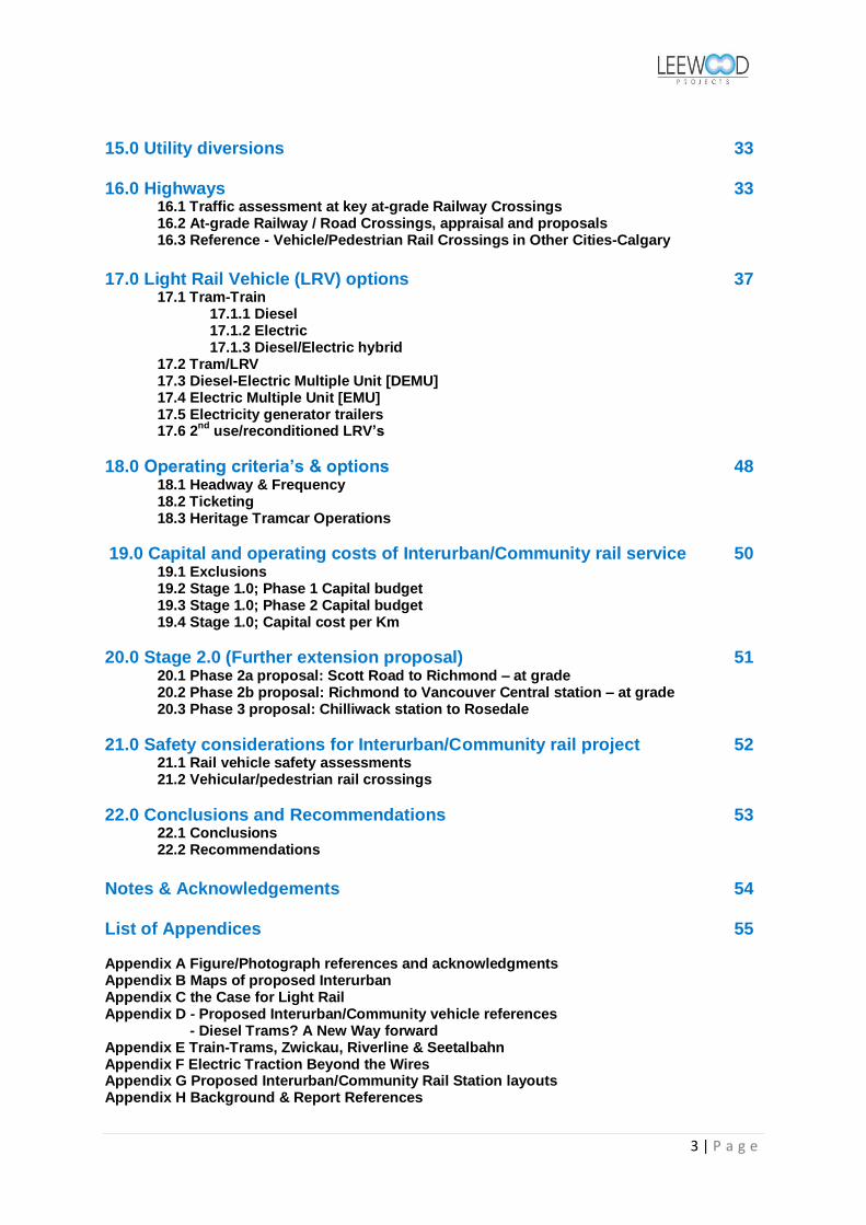
2.0 Introduction First Interurban Train Bound for Chilliwack
October 3 1910 - Last Spike Driven on Chilliwack Tramline Premier McBride Officiates at History-making Ceremony at Chilliwack
Fig 1.
Chilliwack. Early this afternoon Premier McBride presided here at the ceremony of "driving the last spike" of the tram extension of the British Columbia Electric Railway Company connecting Vancouver and New Westminster with Chilliwack by means of a line equipped to be operated by electricity and tapping every part of the rich and fertile south Fraser Valley.
The ceremony was performed in the presence of a notable assembly as was fitting on an occasion when is admitted to mark a new era in the development of the southern mainland. Lieutenant Governor Paterson came from Victoria to participate in the occasion. Premier McBride took the leading part in the function. Other members of the provincial executive accompanied him. From Vancouver and New Westminster cam a large deputation of the civic authorities as well as representatives of the boards of trade while every municipality tapped by the new line was represented by the rank and file of its councillors. Every leading official of the British Columbia Electric Railway Company was on the spot including General Manager Sperling, Assistant General
A BCR Interurban leaves Chilliwack station

6 | P a g e
Manager Glover, and Superintendant Allan Purvis, under whose London board three survey parties were at once sent out to run trial lines. To Mr. F.N. Sinclair, C. E. was allotted the field covering the route finally selected and officials of the road today admitted that when Mr. Sinclair was sent out there was but little thought that the extension would be constructed according to his surveys. His report, however, showed such grades and promising territory tapped that it received far greater consideration than was anticipated and was finally approved as covering the selected route.
How well the company has done its work was testified to today as praise without stint was given by members of the party making the first through run over the line, the journey winding up with the "last spike" ceremony at Chilliwack. This party set out from Vancouver at 9 o'clock this morning and proceeded to New Westminster by way of Eburne and the line along the North Arm of the Fraser. At New Westminster it was joined by the Royal City delegates and at 10 o'clock started on the opening trip over the Chilliwack extension proper.
First Through Run The first stop was made at Cloverdale where is located a substation of the company. This is one of the five from which the current operating the line is sent on the wires, the locations being Cloverdale, Langley, Matsqui, Sumas and Chilliwack. Only the Cloverdale, Matsqui and Chilliwack stations were in operation today but the other two will be in service before the close of the month. The substations are thoroughly fireproof structures and, with electrical equipment, each represents and expenditure of over $25,000.
At Cloverdale the members of the Surrey Council were taken on board and the run through Langley municipality made with a stop at Milner to take on the municipal councillors from that district. Matsqui was the next section traversed, the municipal representatives joining the party at several stations. At Huntingdon, on the international boundary line, members of the party learned that the tram company has a terminal site covering a large area, this leading to the immediate conclusion that the concerns was well located at the international boundary to link up with some electric traction company operating in Washington, thus forming the Seattle-Vancouver tram system such as is judged to be one of the certain developments of the near future. At Sardis the official opening party was completed by the representatives from Chilliwack joining the number and the train then proceeded without stop to Chilliwack where the last spike was driven and the line formally declared open.
Vast Area, Rich Land Not only is the territory tapped by the line one which will be a valuable source of food supplies but in many parts it is covered with valuable timber areas which have heretofore been untouched because of lack of transportation facilities. Members of the party commented on this fact while on the trip of the day and the officials of the tram company promptly replied that in ordering the rolling stock for freight purposes over the extension consists of 100 flat cars, 30 box cars and the ten stock cars. For hauling the freight traffic three powerful electric locomotives were ready for service and others were on the section of the line which has already been in operation for some months, as the need developed. Interviews with the municipal councillors from the various districts on the train showed the large area of rich country which will be opened by the new tramline the acreage being as follows: Surrey, 75,000; Langley, 77,000; Matsqui, 55,000; Sumas, 20,000; and Chilliwack, 70,000. The districts are improved to a varying degree, but it was stated that in no case has the improvement reached the standard which will immediately result on account of the transportation facilities afforded by the operation of the new line. The land was said to be admirably fitted to form the base of food supplies

7 | P a g e
for the hundreds of thousands who will certainly live in Vancouver and New Westminster in the near future. In the words of one rural representative, "you need us and we need you and this line is going to be the connecting link which will bring us together for our mutual advantage." After the "last
spike" ceremony, the official party opening the line sat down to a sumptuous banquet.1
The passenger service continued until 1950 when the costs of upgrading the now forty year old tracks and rail cars proved to be too much, especially in the face of new forms of transit. 100 years ago, the first Chilliwack-Vancouver Interurban rail service began, and it fundamentally shaped the growth of the Fraser Valley. In the second decade of the new millennium, public, municipal & business interests advocate building a new, modern light rail network for the entire Lower Mainland, starting inexpensively with track that already exists, giving the public a real alternative to the automobile.2
3.0 Background
There has long been a sentiment among the populace of the Fraser Valley to bring back the interurban passenger rail service that was suspended in 1950. The campaign became more organized in the 2000's, with the formation of the Fraser Valley Heritage Railway Society (2001) http://www.fvhrs.org/index.htm , a Surrey-based group which aimed at getting a heritage service up and running on the interurban tracks, and then in 2004 with the Valley Transportation Advisory Committee VALTAC http://www.valtac.org/, a Langley-based group representing a South of Fraser regional perspective, advocating for a modern interurban community rail service. In August 2007, a valley-wide movement initially emerging out of Chilliwack, Rail for the Valley was formed. RftV resonated with residents along the Fraser Valley, and was very active, putting on many public forums, community and valley-wide actions, and acting as a vocal advocate in the media for interurban passenger rail. http://www.sfu.ca/~jwbuker/rail/index.htm and http://rftv.wordpress.com/ South Fraser OnTrax was formed in 2008, another Langley-based group advocating for the Interurban. http://www.southfraser.net/ In the following years, politicians took note, and the South of Fraser Rail Task Force was formed by Langley Township Mayor Rick Green in 2009.

8 | P a g e
4.0 Benefits of Interurban & Community rail strategy
The BCER interurban rail corridor was built in 1910, as a major passenger transit corridor. When the line was first built, it served a Fraser valley population of 18,000. When the Fraser Valley passenger service was suspended in 1950 there were less than 80,000 people living throughout the Valley; today over 800,000 people live in Valley communities. The route is still intact and operating for freight. The freight rights are held by Southern Railway of BC along the entire route and an approx 7 mile stretch through Langley is also leased to heavy freight serving Deltaport. To re- introduce passenger transit to the line would therefore once again serve to connect the Fraser Valley communities to promote both the economy and the liveability of the region.3
The Case for Light Rail 4
Environmental Benefits
LRT produces environmental benefits because: It has a proven ability to attract motorists out of cars, thus reducing pollution and congestion
It produces no significant pollution at the point of use and offers the opportunity to operate
on renewable or clean energy throughout the power supply chain
It can help focus development, rather than encouraging urban sprawl.
[Appendix C – Key Arguments]
Affordable and sustainable Light rail/tramways for smaller towns & cities 5
A presentation given by James J. Harkins MCIT MILT of Light Rail (UK) Ltd, to John Moores University
Liverpool; looking at Trams, present and past, current problems of pollution and congestion, and the
resulting consequences for health. Why modern trams are so successful in reducing these problems.
http://www.lightrailuk.com/pdf/affordable_power_point.pdf
9 | P a g e
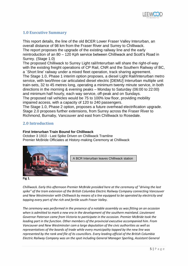
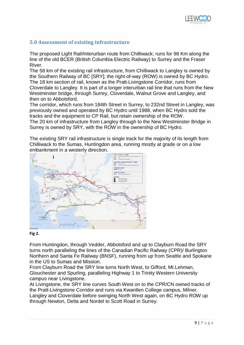
5.0 Assessment of existing infrastructure The proposed Light Rail/Interurban route from Chilliwack; runs for 98 Km along the line of the old BCER (British Columbia Electric Railway) to Surrey and the Fraser River. The 58 km of the existing rail infrastructure, from Chilliwack to Langley is owned by the Southern Railway of BC [SRY]; the right-of-way (ROW) is owned by BC Hydro. The 18 km section of rail, known as the Pratt-Livingstone Corridor, runs from Cloverdale to Langley. It is part of a longer interurban rail line that runs from the New Westminster bridge, through Surrey, Cloverdale, Walnut Grove and Langley, and then on to Abbotsford. The corridor, which runs from 184th Street in Surrey, to 232nd Street in Langley, was previously owned and operated by BC Hydro until 1988, when BC Hydro sold the tracks and the equipment to CP Rail, but retain ownership of the ROW. The 20 km of infrastructure from Langley through to the New Westminster Bridge in Surrey is owned by SRY, with the ROW in the ownership of BC Hydro. The existing SRY rail infrastructure is single track for the majority of its length from Chilliwack to the Sumas, Huntingdon area, running mostly at grade or on a low embankment in a westerly direction.
Fig 2.
From Huntingdon, through Vedder, Abbotsford and up to Clayburn Road the SRY turns north paralleling the lines of the Canadian Pacific Railway (CPR)/ Burlington Northern and Santa Fe Railway (BNSF), running from up from Seattle and Spokane in the US to Sumas and Mission. From Clayburn Road the SRY line turns North West, to Gifford, Mt.Lehman, Glouchester and Spurling, paralleling Highway 1 to Trinity Western University campus near Livingstone. At Livingstone, the SRY line curves South West on to the CPR/CN owned tracks of the Pratt-Livingstone Corridor and runs via Kwantlen College campus, Milner, Langley and Cloverdale before swinging North West again, on BC Hydro ROW up through Newton, Delta and Nordel to Scott Road in Surrey.

10 | P a g e
Assessment of existing track asset:
In August 2009, a visual inspection of three sections of the rail corridor in the Sardis, Abbotsford & Langley areas was made. The speed limit on sections of the SRY rail corridor, a freight line is 20 mph (32 kph). To upgrade the line for 80 to 100 kph (50 – 63 mph) Light Rail/Interurban train service running, will require a programme of track renewal to upgrade the existing infrastructure.
30 ft jointed Bullhead rail – 85/97 1b/foot in chairs - condition fair
`Old for new/like for like‟ replacement, per schedule section 11.0
Hardwood sleepers (ties) - condition poor to fair
Part/full replacement, per schedule section 11.0
Turnouts & switches – condition fair
Replacement with new turnouts & switches, per section 11.0 1. New station track layouts 2. Provision of passing loops 3. Provision of powered facing & sprung trailing switches.
Assessment of Civil Engineering asset:
The permanent way ROW of the SRY/BC Hydro railway has been laid at grade, in a valley corridor that also includes the River Fraser, Highway 1A & the Trans-Canada Highway 1. The ROW has been constructed on a shallow embankment, except for a few sections in the Sardis, Yarrow and Langley areas where the ROW is adjacent or alongside public roads. Construction of the ROW is traditional with graded crushed rock and earth `hoggin‟ forming the sub-grade to the permanent way. Crushed rock track ballast, secures the track ties in position; the 2009 visit indicated areas that had been re-ballasted and areas where the track ballast was low particularly at the shoulder of the ties. Structures on the ROW of the SRY/BC Hydro railway are of three types (table 2.)
a. Rail-Over bridges – Highways and roads b. Rail-Over bridges –Rivers and streams c. Rail-Under bridges – Highways and roads
The structures seen were noted, to be all maintained and in fair condition, although 10 – 20mph speed restrictions are in place on all rail over bridges.

11 | P a g e
Assessment of signalling asset:
The SRY/BC Hydro railway is operated and controlled under the Canadian Rail Operating Rules (CROR), as with railways of BCR, CPR & CN. The CROR rules are intended to enhance railroad safety. 6
The rules cover employee responsibilities, signalling equipment, procedures for safe train movement, dealing with accidents and other topics that directly and indirectly affect railroad safety.
On the SRY/BC Hydro railway, subdivisions or portions of subdivisions as specified in the time table or special instructions, the use of the main track is governed by Occupancy Control System (OCS) Rules. 7 The Automatic Block Signalling (ABS) 8 system is used on the SRY/BC Hydro single track lines. ABS systems for single track were designed in the timetable and train order days to allow trains to safely follow each other closer than what would have been possible with timetable and train orders alone The ABS system protects a single track line including any sidings along it. The sidings are used to meet or overtake trains. All signals are automatic and there is no interlocking or Centralised Traffic Control (CTC) system on an ABS line. Switches are thrown by the train crew as needed. ABS lines may span hundreds of miles without any controlled signals.

12 | P a g e
Assessment of stations & platforms asset:
The existing station at Chilliwack is on the Canadian National (CN) line & ROW. The station is served by VIA Rail's The Canadian three times per week as a flag stop. The station is only served by westbound train to Abbotsford and Vancouver.
Fig 3. Fig 4.
The Abbotsford railway station, located at Matsqui, is on the Canadian Pacific (CP) line & ROW is served by VIA Rail's The Canadian three times per week as a flag
stop. The station is only served by westbound train to Vancouver. West Coast Express operates a weekday commuter service from Mission to Vancouver Waterfront with five westbound morning trains and five eastbound afternoon trains.
Fig 5.
It is not proposed to utilise the existing Abbotsford station as the Matsqui location is not a `Trip Generator‟ for the Interurban; however the Chilliwack Interurban station facility, could be incorporated into the existing VIA station yard subject to access agreements being negotiated. There are no other station facilities, on the SRY/BC Hydro railway, which could be utilised for the Interurban.

13 | P a g e
Assessment of grade road crossings & associated signalling asset:
The SRY/BC Hydro railway is operated and controlled under the Canadian Rail Operating Rules (CROR). 6 Transport Canada http://www.tc.gc.ca/eng/menu.htm is responsible for transportation policies and programs. It ensures that air, marine, road and rail transportation are safe, secure, efficient and environmentally responsible. Transport Canada is the agency responsible for regulations, standards and programs work to ensure the safety of grade road crossings. Canadian Transport Agency www.cta.gc.ca resolves disputes on rail crossings (including the apportionment of costs) between federal railways and other parties who may interact with those railways. The standard North American method of grade crossing control equipment is the Grade Crossing Predictor; such devices rely on the characteristics of tuned loops being altered by the presence of train wheelsets. The detected alteration is processed and then determines the arrival time of the train at the grade crossing. Such devices drive audible and visual warning devices and where fitted, barrier mechanisms. There is no interlocking with signalling systems, or monitoring by train drivers or signalmen. They are also known as Motion Detectors and Constant Warning Time Devices. Existing grade crossings of the SRY/BC Hydro railway are of three categories:
Gated & signalled (Gate & light protected) Scott Road 120th Street & 99th Avenue, Surrey
Fig 6. Un-gated & signalled (Light & bell protected) 7124 King George Highway 99A, Surrey
Fig 7.

14 | P a g e
Un-gated & un-signalled (Stop sign protected) 45770 Airport Road Chilliwack
Fig 8.
Full details of the existing Grade Crossings and recommendations from the study are detailed in Table 3.
Assessment of Depot & Control room options
The optimal preference for a purpose built depot & control room facility is between Cloverdale in Surrey and New Westminster. A study of existing depot locations; for a maintenance workshop, washing plant and vehicle stabling roads and an additional satellite yard in Abbotsford, on industrial lands adjacent to the rail line and with road access, in Surrey was undertaken. The utilisation of the CP/CN/SRY heavy maintenance base at Trapp Road Burnaby for the Interurban Phase 1, was ruled out because of the cost of vehicle transfers to the west side of the Fraser River. The study did not find an existing facility that could be adapted for Interurban use. The recommendations from the study and the new depot proposals are detailed in section 9.0

15 | P a g e
6.0 Stage 1.0 (Initial scheme) The Canadian Transportation Agency www.cta.gc.ca processes applications for certificates of fitness for the proposed construction and operation of railways, and approvals for railway line construction. The Agency has primary responsibility for carrying out the provisions of the Canada Transportation Act. http://laws.justice.gc.ca/en/C-10.4/index.html It also shares responsibility for the following laws: The Railway Safety Act (1985) The Railway Relocation and Crossing Act (1985)
6.1 Phase 1 proposal: Chilliwack to Scott Road – Diesel Light Rail upgrade
The proposal calls for the upgrading of 98 km of the SRY/BC Hydro railway between Chilliwack & Scott Road Surrey, to an 80 – 100 Kph Interurban/Community rail route, with diesel or LPG/diesel electric Tram Trains, Light Rail Vehicles (LRV) or Multiple Units (MU) The scheme proposal will include:-
Retention of existing single track ROW.
Upgrading of permanent way ROW; embankment stability, drainage and corridor enhancement for minimum 80 Kph running. (sections 10.1& 10.2)
Improvement of structures on route; culverts and bridges including enhancement of rail over bridges for minimum 80 Kph running. (section 10.3)
Renewal & replacement of track rails, track ballast, ties & switches, upgraded for minimum 80 Kph running. (section 11.0)
Retention of existing passing loops. (section 11.3)
Laying a 1 km switched spur, off the SRY Interurban between Old Yale Road and 110th Avenue, with a new grade crossing of 110th Avenue near the intersection of 126A Street, to a new terminus at the Scott Road Sky Train station car park at 120th Street. The land corridor that connects the Sky Train station with the Interurban track is in the ownership of the City of Surrey.
Provision of ten stations, with signalled double track passing loop, two platforms with one serviced station building and one weatherproof shelter.(section 7.1)
Provision of a minimum of six tram stops with signalled double track passing loop, two platforms, with one weatherproof shelter per platform. (section 7.2)
Depot, maintenance shop & control centre. (section 9.0)
Enhancement of signalling control system.(section 12.2)
Installation of enhanced communication systems.
Installation of passenger operated ticketing machines and assistance points.
Upgrading & replacement of, at grade road crossings, where applicable. (table 3)

16 | P a g e
6.2 Phase 2 proposal: Chilliwack to Scott Road – Electrification upgrade
The Phase 2 proposal calls for electrification of the upgraded 98 km Phase 1 Interurban/Community rail route between Chilliwack & Scott Road Surrey, with a 750 v DC supply for 80 – 100 Kph electric Tram Trains, Light Rail Vehicles (LRV) or Multiple Units (MU). The proposal is based on substations at 10km intervals, 9 No + one at each terminus & one at the depot; total 12 No. Overhead contact wire, single supported on droppers from single off-set poles at 20m intervals. The proposed track layout at stations will have a switched passing track off the single line, the overhead line [OHLE] will supported from span wires between pairs of poles. The Phase 2 electrification proposal will have to address the diversion/relocation of the BC Hydro overhead electricity transmission and feeder distribution lines, which have been installed on both sides of the ROW for much of the proposed Chilliwack to Surrey Interurban‟s length. For the high voltage 3-phase transmission lines, relocation will be more than likely necessary; for the low voltage single-phase feeder distribution lines, sharing of a common pole with the Interurban may be possible subject to mitigating stray current leakage & potential electromagnetic interference (EMI)
7.0 Proposed Rail Stations, land use and employment opportunities The Chilliwack to Surrey Interurban scheme proposes, the provision of ten stations, with signalled double track passing loop, two platforms with one serviced station building and one with a weatherproof shelter and six tram stops with double track platforms, signalled passing loop and one weatherproof shelter per platform. Foot passenger and bicycle access, from one platform to another will be by way of boarded foot crossing, sited at the extremities of both platform ramp ends. The platform height & consequent ramp to the foot crossing will be dependent on the proposed LR vehicle boarding height. The ramps and foot crossings will be designed to be compliant with Federal & Provincial disabled access requirements.(see Fig 9 & 10)
Fig 9. Beddington Lane Fig 10. Morden Road Croydon Tramlink Croydon Tramlink

17 | P a g e
7.1 Railway Stations
Purpose built, traditional Canadian BC single-storey design; timber frame with marine ply sidings, larch cladding & larch roof shingles. Proposed building footprint: 300 to 500 m2 [3000 to 5000 ft2], subject to available land area.
Services:-
1. Mains or sceptic tank drainage. 2. Potable water supply 3. Electrical power – The report proposes installation of roof mounted
photovoltaic panels, solar water heating panels and a small wind turbine (subject to land area) to generate a total of about 20 -30 kW. Sufficient to heat building, heat water & power all facilities. Surplus generated electricity could be routed into the grid & sold back to BC Hydro. It is envisaged that a metered connection from the local BC Hydro grid is also provided so as to ensure continuity of electrical supply.
4. Telephone, Internet connection
Facilities:
Washrooms.
Deli & grocery store.
Coffee shop/Internet café.
Bank ATM
Small community meeting/conference room, gallery etc
Ticketing will be via Passenger operated ticket machines (POM); cash & Smart Cards
Passenger help/information point, GSM-R connection to control room, also local RCMP office
Platform Information display [next train countdown] also GSM-R connection to control room.
External platform lighting.
External platform CCTV.
Platform seating.
Platform information & advertising frames.
Platform litter bins. Platform surfacing, local stone or PC concrete slabs. Platform height
dependant on vehicle loading height.

18 | P a g e
With the possible exception of an information desk, which could double as tourist information centre, car rental desk etc all facilities would be run as a concession by a local business/community organisation. The station building design is `modelled‟ on traditional Canadian rural railroad designs - examples:
Fig 11. Sackville New Brunswick
Fig 12. Casselman Ontario
Fig 13. Pemberton British Columbia
Reference details at: http://yourrailwaypictures.com/TrainStations/ http://www.flickr.com/photos/84263554@N00/2330441312/ http://www.flickr.com/photos/ssmt/sets/72157600516234012/

19 | P a g e
It is a key, that the interurban is accepted by the local population; therefore the stations should become a community focus point, with facilities for meetings; antiques, art & craft shows and sales.
Station List:
1. Scott Road. (Sky Train connection) 2. Delta/Nordel Way (or 90th or 92nd Avenue) 3. Newton/King George. 4. South Surrey/152nd Street. 5. Cloverdale/176th Street. 6. Langley, 200th Street 7. Maclure.(Maclure Business Park in Abbotsford) 8. Yarrow. 9. Sardis, Knight Road. 10. Chilliwack Station, Yale Road W and Young Road
7.2 Tram stops
In addition to above 10 stations, there would be 6 additional stops similar to the
example in figure 14, at:
11. Chilliwack Airport Rd (University of the Fraser Valley Chilliwack Campus) 12. Huntingdon (Abbotsford Airport connection) 13. Abbotsford, Marshall Road. 14. Abbotsford, Essendene Avenue. 15. Trinity Western University. 16. Kwantlen Polytechnic University (Langley campus)
The tram stops could be like the image of a `decor style‟ French tram stop, in this case Vincent Gâche on the Nantes tramway.
Fig 14.
Facilities:
Canopy.
Pole mounted photovoltaic panels for power provision, also connection to local electricity grid.
Passenger operated ticket machines (POM); cash & Smart Cards

20 | P a g e
Passenger help/information point, GSM-R connection to control room, also local RCMP office
Platform Information display [next train countdown] also GSM-R connection to control room.
Platform lighting.
Platform CCTV.
Platform seating.
Platform litter bins
Platform surfacing, local stone or PC concrete slabs. Platform height dependant on vehicle loading height.
Information & advertising poster frames. The actual location of the new Community Rail stations and Tram stops will be determined in the final Interurban scheme by:-
Land availability & cost/Land use variables o Parking space
Access from public highways o Park-and-ride space
Population & Employment within walking distance
Trip Generators
Traffic generation
Pedestrian Access
Rights of Way negotiation
Services and utility connections
Station Spacing
Detailed appraisal of existing track vertical & horizontal alignment
Detailed assessment and design of passing loops, with regard to transition curve geometry
Signalling Sighting Lines & distances
8.0 Accessibility improvements for rail stations
8.1 Automobile Access & Parking
The scheme proposes that stations & tram stops are located close to existing highways and roads. Provision of access and parking facilities will be incorporated into the location and site layout design. Sharing of parking facilities, with an existing provider; a shopping mall, grocery market etc would be favoured over constructing a new area for parking.
8.2 Pedestrian & Mobility Impaired Access
All proposed Interurban stations & tram stops, will be located, designed and constructed with access for pedestrians and specifically the disabled/mobility impaired taken into consideration at the conceptual design stage of the project, taking into consideration Federal & Provincial acts & statutes.

21 | P a g e
8.3 Feeder & Shuttle Bus Connections
This Interurban report proposes integration of services with the scheduled bus services in the Central & Lower Fraser Valley; Surrey, Langley, Aldergrove, Mission, Abbotsford & Chilliwack operated by TransLink and BC Transit/FirstCanada ULC. There is a potential for a summer bus shuttle, for the 15 minute journey from Yarrow Station to Cultus Lake. Cultus Lake is a popular destination for people throughout the Fraser Valley.
8.4 Cycling Facilities (Carriage of Cycles)
A key consideration for the planning, upgrading and delivery of the Lower Fraser Valley Interurban will be provision of facilities for carriage of bicycles. As by way of a comparison: SkyTrain permits bicycles on board except during rush-hour times, and with restrictions of 2 bicycles per car. http://www.translink.ca/en/Cycling/Bikes-on-Transit/Bikes-on-SkyTrain.aspx Calgary's C-Train permits bicycles on board except during rush-hour times, and with restrictions of 4 bicycles per car. http://www.calgarytransit.com/html/bikes_on_board.html Edmonton Transit System [ETS] permits bicycles on board except during rush-hour times. http://www.edmonton.ca/transportation/ets/bikes-on-ets-lrt.aspx West Coast Express permits bicycles, with no service restrictions, but with a 2 bicycles per car limit: http://www.westcoastexpress.com/bike.asp?PageID=SERVICEINFO&MenuSubID=BIKELOCKER Toronto Transit Commission (TTC), prohibits carriage of bicycles on the current ALRV & CLRV streetcar services, but will permit bicycles to be carried on the new generation LRV‟s to be introduced. OCTranspo, operators of Ottawa‟s 0-Train, permit the carriage of bicycles: http://www.ottawa.ca/residents/onthemove/travelwise/cycling/cy_8_en.html In the USA, TriMet, the operators of the Metropolitan Area Express (MAX) Light Rail system, permit the carriage of cycles but with restrictions: http://trimet.org/howtoride/bikes/index.htm Sound Transit, the operators of Seattle‟s Central & Tacoma Link‟s Light Rail systems, permit the carriage of bicycles, with no service restrictions, but with a 4 bicycles per car limit: http://www.soundtransit.org/Riding-Sound-Transit/How-To-Ride/Bicycles.xml#CentralLinkLightRail

22 | P a g e
This report for the Lower Fraser Valley Interurban, proposes that the carriage of bicycles is permitted, with the following service restrictions:
Weekday, morning & evening peak services – 2 bicycles per car limit. Weekday, off peak – 4 bicycles per car limit. Weekends – 6 bicycles per car limit.
It is proposed, that cycle & touring clubs can arrange in advance with the operator, for permits enabling carriage of additional bicycles on specific services. It is not proposed to include dedicated vehicles fitted with racks for the carriage of cycles on the Interurban because of the increase to the loading (dwell time) at 15 No intermediate stations & stops, between Chilliwack & Scott‟s Road. Estimated at 1½ minutes dwell at each station, for bikes to be loaded/ unloaded, secured & for passengers to make their way to the cars which would add a total of 22½ minutes on the journey. The one exception might be the option, for the incorporation of an electricity generator trailer in the train/tram set, (section 17.5) also Appendix F; additional cycle storage being accommodated in this car. The Vancouver Area Cycling Coalition (VACC) 9 http://www.vacc.bc.ca/ actively
advocates for better cycling facilities in the Lower Mainland; relevant issues to the Interurban proposal would include:
Bike access to Interurban stations & Tram stops
Bike carriage on the Interurban
Bike lockers and racks at Interurban stations & Tram stops
9.0 Depot, Maintenance & Control Centre
1. Single depot proposal. 2. Depot, workshops, control room & offices in the Abbotsford area, central
location almost equidistant from Surrey & Chilliwack. 3. Second stabling area or layover area, with fence & security and small facility
for crews signing-on, washrooms & cafeteria, in Surrey near the Scott Road terminus.
4. A `turn-back‟ siding with storage for 3 – 4 LRV‟s (during operating hours) at
the interim Chilliwack terminus, laid as spur off the stub end, for the Phase 3
extension to Rosedale is proposed.
a. The depot land take, would be in the order of 4-5,0000 m2 b. Provision of external stabling, 6 roads with vehicle, internal valeting
facilities c. Depot, 4 road industrial building, steel frame & cladding; stores,
inspection pits, bogie/wheel drop, wheel lathe, body repair shop, traction train repair shop.
d. Fuelling facilities, storage tanks & dispensers, for diesel LRV‟s e. Control room built adjacent or integral with depot, offices, training
room, welfare facilities, cafeteria, washrooms, and locker rooms. Staff car parking.

23 | P a g e
f. Separate washer road & washer plant (large car wash). Also sand silo for vehicle sanders
g. Separate road [for Road-Railers/on-track plant] & building/shed for permanent way maintenance crews, including truck parking and stores.
h. Security entrance gate, fenced & CCTV controlled. i. Provision of roof mounted photovoltaic panels, solar water heating
panels and a wind turbine to generate a total of about 60 -70 kW. Sufficient to heat building, heat water & depot power requirements, also connection to local electricity grid.
An example is the proposed new Starr Gate depot for the modernised Blackpool –
Fleetwood system in UK.
Fig 15. Fig 16.
Plan of proposed depot http://www.tramstore21.eu/sites/default/files/247030-SK-010_p1.pdf Details of planning, design & construction of a tram depot: - http://www.tramstore21.eu/
The actual location of the new Depot, Maintenance & control Centre will be determined in the final Interurban scheme by:-
Land availability & cost/Land use variables
Compliance with the functional statements and City & Provincial development zoning and conditions
Access from public highways for Low –Loader trucks.
Availability of local skilled labour
Rights of Way negotiation
Services and utility connections
Detailed appraisal of existing, entry road vertical & horizontal alignment
Signalling Sighting Lines & distances for depot entry road
24 | P a g e
10.0 Infrastructure - Civil Engineering
10.1 Drainage
The report proposes enhancement of existing ROW drainage, to ensure adequate rainwater run-off and the prevention of flooding. Specific improvements are proposed for track drainage in the vicinity of at-grade highway & road crossings and new drainage for stations & tram stops. As in the case of the existing SRY/BC Hydro railway, surface water will be discharged into ditches along the ROW.
10.2 Bridges & culverts
A number of culverts, carrying minor water courses under the ROW, will require realignment or replacement as part of the line upgrade. A key requirement will be to maintain embankment stability and mitigate any likelihood of flood damage & washout due to spring snow-melt. The report does not envisage any work being necessary to the rail-under bridges, scheduled in Table 2. These structures carry highways & roads over the railway ROW and would be in the ownership of the BC Provincial or city/town highway authority, which would also be responsible for maintenance & upkeep. Table 2 lists twelve rail-over bridges, in which responsibility for maintenance & upkeep would lay with the SRY/BC Hydro. All these structures will require an inspection, survey and evaluation to assess the degree of enhancing and strengthening required to enable 80 kph running.
10.3 Earthworks/embankment stability
For the majority of its 98 Km length the SRY/BC Hydro railway runs at grade or on shallow embankments. In the Chilliwack sub-districts of Yarrow, Arnold and Upper Sumas; between the Vedder River & Huntington, the ROW runs on an approximately 3 meter high embankment. An inspection, survey and evaluation to assess the stability of the embankment and whether Geotextile strengthening or Soil Nailing is required to enable 80 kph running.

25 | P a g e
11.0 Infrastructure - Permanent Way
Sources in have been referenced by the author, in the preparation of this and other report sections, relating to the Interurban right-of-way [ROW], permanent way alignment and track design & renewal. 10 References to specific sections are listed in
the Acknowledgements and Appendices – Appendix H
Summary assessment of track renewals – proposed schedule:
General System Requirements
The trackwork design should apply a design philosophy that will provide continued acceptable performance, ease of operation and maintenance, and stresses the following principles: • Minimal changes to the design of the existing SRY/BC Hydro permanent way. • Ensuring design compatibility with existing trackwork components • Interchangeability • Modular design • Use of standard off-the-shelf components • Maintainability • Availability and reliability • Ability to interface with work to be done by other disciplines Based on preliminary assessment of:-
a. 30% spot renewal [1 in 6 tie replacement and 50% of rail length], re-ballasting shoulders, tamping top & line
b. 30% heavy renewal [all ties & 100% rail length], complete lower ballast replacement, re-ballasting shoulders, tamping top & line
c. 40% ballasted track replacement, [including new rail, ties & ballast] plus sub-grade & drainage upgrading, to permit higher speeds.
11.1 Track [ROW] design and upgrade
An important consideration of the proposal is to differentiate between light rail transit track and those similar, but subtly different, track systems used for freight, commuter, and heavy rail transit operations. These differences present challenges both to light rail track designers and to the designers and manufacturers of light rail vehicles. Much research has been conducted in an effort to understand the mechanisms involved in track-vehicle interaction and its impact on track design. However, no widely accepted guidelines exist to specifically aid in the design and maintenance of light rail transit track. Consequently the light rail transit industry frequently relies on practices developed primarily for heavy rail transit and railroad freight operations that are not necessarily well suited for light rail systems. 10a
Key parameters include:-
Wheel profile
Wheel/Rail interface
Restraining wheel flange lateral movement on curved track work & switches

26 | P a g e
Track horizontal alignment
Track vertical alignment
Gauge issues for joint LRT and Railroad (mixed fleet) operations Wheel profile is one of the most critical vehicle parameters to consider in track design, since the wheel is the primary interface between the vehicle and the track. The wheel profile must be compatible with the rail section, in particular special trackwork components; 10a
I. Switch points II. Frog flangeways or moveable point sections
III. Guard rails, protecting special trackwork components or restraining rail positions on short radius track curves.
Many transit agencies have adopted a “worn wheel” design, featuring wheel contours that approximate the template to which railway wheels wear in service. These designs are intended to:
Reduce wheel and rail wear
Reduce likelihood of derailment under adverse operating conditions
Enhance stable performance over the nominal range of speeds
Provide reasonable contact stress characteristics. Wheel profile is a flexible design decision, drawn from the different profile sections used throughout the transit industry. The same flexibility is not provided in the selection of standard rail profiles. Only a few standard rail sections exist for use by the transit industry. However, wheel and rail profiles must be compatible, which means that the wheel profile should conform to the rail head profile. As with wheel profiles, the majority of the research and development on rail head profiles and rail profile grinding has been undertaken by and for the railroad industry. The transit industry can also benefit from this research. However, recommendations for heavy haul railroads may not be entirely applicable to the transit industry. A light rail vehicle weighs (AWO) approximately 44,000 kilograms (97,000 pounds). A loaded freight car weighs as much as 152,000 kilograms (335,000 pounds). This represents a significant difference in wheel loads of 5,500 kilograms (12,100 pounds) and 19,000 kilograms (41,900 pounds) for LRVs and freight cars, respectively. Obviously, rails used in transit service will not be subjected to wheel forces of the magnitude exerted by freight cars. Therefore, theories of rail gauge corner fatigue, high L/V ratios, and the threat of rail rollover that pertain to freight railroads may not be fully applicable on a transit system. The contact forces at the rail gauge corner on curved tracks are usually twice as large as those between the rail crown and wheel tread. To reduce contact stresses at the gauge corner and gauge side rail base fastening, it is important that the wheel/rail profile be compatible. The wheel profile is conformed to the rail profile if the gap between the wheel and rail profile is less than 0.5 millimetres (0.02 inches) at the centre of the rail (in single-point contact) or at the gauge corner (in two-point contact). 10a
To improve wheel/rail interface contact, alternate wheel shapes may be considered. During the early design stage of new transit systems, transit wheel profiles should be considered that match or conform to the rail section(s) to be used on the system.

27 | P a g e
In the process of wheel design, the design engineer must consider the rail sections and the rail cant to be selected. 10g
The successful guidance of a moving rail vehicle will be governed by the response of the vehicle to deviations in the track geometry, known as Vehicle-Track Interaction (VTI), either by design (curves, switches, etc.) or because of component degradation. In turn, the response of the vehicle to the track is significantly affected by the interaction of each rolling wheel with the rail and the contact conditions between the wheels and rails. A derailment is often the result of many factors combining to create an undesirable VTI situation. For example, a modest track twist (change in cross level) near a curve worn switch point could lead to less than desirable wheel/rail contact geometries and the potential for a wheel to climb over the rail, particularly for stiffly suspended trucks. Several VTI scenarios can lead to derailment, including wheel climb resulting from excessive lateral forces at the wheel/rail interface as compared to vertical forces at the same interface, gauge widening and rail rollover, vehicle lateral instability, high wheel loads and their effect on switch components and the forces on the rail that can be generated by hollow worn wheels. The scenarios that could lead to derailments & the strategies to prevent occurrences, by restraining wheel flange lateral movement on curved track work & switches can be found in the Ensco Inc paper Ref 10h
Light rail transit (LRT) geometry standards and criteria differ from freight or commuter railway standards, such as those described in applicable sections of the American Railway Engineering and Maintenance-of-Way Association (AREMA) Manual, Chapter 5, in several important aspects. Although the major principles of LRT geometry design are similar or identical to that of freight/commuter railways, the LRT must be able to safely travel through restrictive alignments typical of urban central business districts, including rights-of-way shared with automotive traffic. Light rail vehicles are also typically designed to travel at relatively high operating speeds in suburban and rural settings. The LRT alignment corridor is often predetermined by various physical or economic considerations inherent to design for urban areas. One of the most common right-of-way corridors for new LRT construction is an existing or abandoned freight railway line. The LRT vehicle is often required to operate at speeds of 65 to 90 kph (40 to 55 mph) through alignments that were originally designed for FRA Class 1 or 2 freight operations; i.e., less than 45 kph (30 mph) General guidelines for the development of horizontal alignment criteria should be determined before formulating any specific criteria. This includes knowledge of the vehicle configuration and a general idea of the maximum operating speeds. Criteria for the design of LRT and freight railroad joint usage tracks are described later in this section. In addition to the recommendations presented in the following sections, it should be noted that combinations of minimum horizontal radius, maximum grade, and maximum unbalanced super elevation are to be avoided in the geometric design. The following geometric guidelines are established to consider both the limitations of horizontal, vertical, and transitional track geometry for cost-effective designs and the ride comfort requirements for the LRT passenger.

28 | P a g e
The horizontal alignment of track consists of a series of tangents joined to circular curves and spiral transition curves. In yards and other non-revenue tracks, the requirement for spiral transition curve is frequently deleted. Track super elevation in curves is used to maximize vehicle operating speeds wherever practicable. An LRT alignment is often constrained by both physical restrictions and minimum operating performance requirements. The vertical alignment of an LRT alignment is composed of constant grade tangent segments connected at their intersection by parabolic curves having a constant rate of change in grade. Maximum grades in track are controlled by vehicle braking and tractive efforts. On main line track, civil drainage provisions also establish a minimum recommended profile grade. In yards, shops, and at station platforms, there is usually secondary or cross drainage available. Joint LRT/Railroad/Freight tracks are designed in conformance with the requirements of the operating railroad and the AREMA Manual, as a guideline, recommended criteria are as follows: The horizontal alignment for joint LRTrailroad/ freight tracks consists of tangent, circular curves, and spiral transitions based on the preferred maximum LRV design speed and the required FRA freight class of railroad operation Lead tracks and industrial spurs generally do not require spiral transitions. Curves adjacent to turnouts on tracks that diverge from the main track should be designed for the maximum allowable speeds of the adjoining turnouts. 10a
Gauge Issues for Joint LRT and Railroad and Mixed Fleet Operations
For a system with a mixed fleet, compromises may be required to accommodate a variety of truck and wheel parameters. This problem is not new-early 20th century electric street railway track designers frequently had to adapt their systems to handle not only city streetcars with short wheel base trucks and relatively small diameter wheels, but also “interurban” trolleys that typically had longer wheel base trucks and larger diameter wheels. Some trolley companies even offered freight service and routinely handled „steam” railroad engines and freight cars over portions of their lines. Today, if the light rail system shares any portion of its route with freight railroad, or if future extensions either will or might share freight railroad tracks, then conformance with freight railroad gauge and other freight geometry constraints will control the track design. When a new light rail system shares track with a freight railroad, freight operations normally occur only along ballasted track segments. It is unusual for freight trains to share aerial structure or embedded track segments of a system. Nevertheless, the mixing of rail freight and LRT operations on any portion of a system will govern track and wheel gauge design decisions for the entire system. Even if the system‟s “starter line” does not include joint operation areas, consideration should be given to whether future extensions of the system might share tracks with a freight railroad. The key issues to consider in accommodating mixed operations are the setting of the back-to-back wheel dimension, guard check gauge, and guard face gauge criteria that result from a particular wheel setting. Track design parameters that will be most affected by these decisions include: 10a
The practicality of using available girder groove and guard rails that are rolled with a specific flangeway width.

29 | P a g e
The flangeway width and track gauge required for effective restraining rail or guard rail applications.
Details for guarding of frog points in special trackwork locations. To mitigate mixed operations, extensive work on minimising the affect of introducing new rolling stock to existing and new lines is desirable. Proposed works include friction management of the rail head gauge corner and the wheel-rail interface, together with a planned programme of rail grinding to a worn wheel profile. Experience from European systems, where similar measures have been undertaken, was that the introduction of new rolling stock to the existing and new tracks has not resulted in increased incidences of rail head wear problems.
11.2 Double track
The SRY/BC Hydro line is single track, for most of the 98 km length from Chilliwack to Surrey; with the exception of a number of passing/freight loops (see section 11.2). The report recommends retention of the single track layout with passing loops; for majority of the ROW, the study has determined the impracticalities and uneconomical cost of double-tracking:-
Acquisition of rights to widen the ROW.
Land purchase costs.
Widening embankments
Relocation of BC Hydro, electricity power poles & cables
Replacement of Rail-Over bridges.
Widening of Rail-Under bridges.
Widening or replacement of at-grade road crossings.
Rise in cost of track & signalling upgrade.
11.3 Passing loops
On the SRY/BC Hydro ROW, between Chilliwack & Scott Road Surrey, there are a total of eight existing passing loops:-
1. Chilliwack – between Young Road & Airport Road. 2. Gifford – Glenmore Road. 3. Spurling – 70th Avenue. 4. Milner – Crush Crescent. 5. Langley – between Highway 1A & 56th Avenue. 6. Langley – between 1st & 6th Street, Cloverdale Bypass 7. Langley – between 80th Avenue & 128th Street. 8. Surrey – 80th Avenue.
The Chilliwack – Surrey Interurban report proposes:-
1. Existing freight Passing loops to remain and be upgraded with; a. Motorised switches and crossings b. Enhanced loop occupancy detection. c. Entry & exit signalling – LED point indicators.

30 | P a g e
2. Installing additional Passing loops at each of the sixteen stations and tram stops, to permit the planned service operation - a timetabled peak service, 20 to 30 minute headway in both directions.
Configuration of the new Passing loops will be determined in the final Interurban scheme by:-
Station & Tram stop alignment.
Detailed assessment and design of passing loops, with regard to transition curve geometry
Signalling Sighting Lines & distances
Loop lengths to suit proposed rail vehicles
The design of the Station and Tram stop, Passing loops are to include:
1. Provision of and replacement of existing manual hand-switched points with motorised Facing & Trailing switches and the possible use of sprung Trailing switches.
2. `Mimic‟ Indicators, advising Control Centre & approaching LRV operator of platform/loop occupancy.
3. Signalled entry & exit to platform Passing loops – LED point indicators On many of the existing passing loops, particularly in the Abbotsford and Langley areas, there are switched spurs off to freight sidings, CP Rail, CNR, Southern Railway of BC and possibly some privately owned. This Interurban proposal will seek to maintain these freight spurs & sidings, with the existing hand operated switches, but with the addition of LED point indicators.
12.0 Infrastructure – Signalling
The use of the SRY/BC Hydro railway, main track is governed by Occupancy Control System (OCS) Rules. The Automatic Block Signalling (ABS) system protects the single track line including the passing loops and sidings along it. The loops and sidings are used for trains to overtake another; switches being thrown by the train crew. All the signals are automatic and there is no interlocking or Centralised Traffic Control (CTC) system on the line. The report recommends the following proposals:-
12.1 Operational running proposals – Time separation
The Stage 1.0, Phase 1 proposal is for a Temporal separation ("time-sharing") operation, with the Interurban operating from 06:00 to 22:00 and freights services from 22:00 until 06:00. The proposal precludes 24/7 Light Rail operations, but to enable an early commencement of Community Rail services, between Chilliwack and Scott Road Surrey, the arrangement will be the simplest to instigate.

31 | P a g e
12.2 Signalling control proposal
Options: 1. Axle Counters – not likely due to cost and resistance from infrastructure
owner 2. Track circuiting - ruled out on cost of installing cabling & power supplies 3. Radio-Token Block [single line] signalling; likely to be resisted by Freight
operators 4. GSM-R controlled via base stations, linked to Control room, which has
visibility of all trains at all time. Light Rail/Interurban and freight trains will be monitored from the Control room and Interurbans can be switched into passing loop to permit freight to pass/overtake. With detection circuits at passing loops to confirm occupancy & settings/position of turn-out/switches. LED point indicators at entrance & exit of each passing loop.
Fig 17.
Prognosis: The Report recommends the adoption of a GSM-R based system, to augment the existing ABS Protection system. GSM-R is typically implemented using dedicated base station towers close to the railway. The distance between the base stations is 7–15 km. This creates a high degree of redundancy and higher availability and reliability. The train maintains a circuit switched digital modem connection to the train control centre at all times. It is used to transmit data between train and control center. When the train passes over a sensor/transponder it transmits its new position and its speed, then it receives back agreement (or disagreement) to enter the next track and its new maximum speed, so by removing the necessity for traditional trackside signalling to be installed. GSM-R will provide:-
Interurban LRV location.
Settings & position of turn-out switches.
Occupancy of Passing loops
Rail right-of-way confirmation at grade highway crossings.
LED Facing point Indicator signal
Nottingham Express Transit

32 | P a g e
13.0 Infrastructure – Communications The Chilliwack – Surrey Interurban report proposes adoption of a GSM-R communications system. GSM-R, Global System for Mobile Communications - Railway or GSM-Railway is an international wireless communications standard for railway communication and applications. http://en.wikipedia.org/wiki/GSM-R GSM-R is a secure platform for voice and data communication between railway operational staff, including drivers, dispatchers, signallers, train engineers, and station controllers. It delivers features such as group calls (VGCS), voice broadcast (VBS), location-based connections, and call pre-emption in case of an emergency. This will support applications such as video surveillance in trains and at stations, and passenger information services. The GSM-R base stations will be sited at 10 km intervals. GSM-R will provide:-
Cab to Control centre communications link
Station to Control centre communications link
Passenger help/information point link
Platform CCTV link
Platform Information display [next train countdown] link
Passenger operated ticket machine link
14.0 Infrastructure – Electrification The Phase 2 proposal for electrification of the upgraded 98 km Phase 1Interurban/Community rail route between Chilliwack & Scott Road Surrey, with a 750 v DC supply for 80 – 100 Kph electric Tram Trains, Light Rail Vehicles (LRV) or Multiple Units (MU), as follows:
12 No 11 kV AC substations at 10km intervals, 9 No + one at each terminus & one at the depot, fed from BC Hydro supplies each with a 1,000 kW transformer rectifier to provide 750 v DC output.
The power supply control in each substation is monitored by the Control Centre using a Supervisory Control and Data Acquisition (SCADA) system for Equipment, Intruder and Fire Alarm status, utilising the GSM-R system.
Single overhead 13mm diameter copper contact wire, supported on droppers from single off-set poles at 20m intervals.
Switched station passing loop, overhead line [OHLE] supported from span wires between pairs of poles.
OHLE tension is maintained by weights mounted on the poles.

33 | P a g e
15.0 Utility diversions The Report has discounted the need for a wholesale diversion of the BC Hydro overhead electricity supply lines and poles in Section 11.2, however to construct the new station and tram stop passing loops, there may be the requirement for limited local diversion, off the ROW of the power lines and poles. Other utility diversions should be limited to areas of:-
Station & Tram stop footprints
Access roads & footways to Station & Tram stops
Enhancing & upgrading, at-grade road crossings
Strengthening & upgrading bridge structures & embankments
Improving track ROW drainage
16.0 Highways In Stage 1.0 of the Chilliwack to Surrey Interurban proposal, highway, road & street diversions and layout changes will be limited to:
Provision of new access roads to station and tram stops
Junction and light control for new access roads to station and tram stop car parks/park & rides
At-grade road crossing enhancement and upgrading
16.1 Traffic assessment at key at-grade Railway Crossings
Traffic assessment for the Lower Fraser Valley Interurban/Community Rail scheme will require a range of issues to be reviewed as project decisions move from a conceptual level to detailed design and operation. This report considers traffic levels in the City of Surrey for which data is readily available. 11 `
Similar studies to chart traffic levels in the Langley, Abbotsford and Chilliwack areas will be needed in order to assess the impacts on existing traffic control signal locations and the corridors that are controlled by the affected signals. The rail line under consideration is used by the Southern Railway of BC (SRY) for freight movement up to four times per day mostly on weekdays. Roadways impacted are under the authority of either the City of Surrey or the Ministry of Transportation (MoT). In addition to roadway corridor issues that impact traffic signal operation there may be local issues immediately adjacent to station locations such as pedestrian access and parking requirements to be reviewed. In general, two vehicles, peak period passenger trains, operating every 20 minutes, will disrupt individual traffic signals cycles for 30-40 seconds, which is considerable less than long freight trains which use the lines.
MoT Highway 10 is affected at several streets in the Cloverdale area including the following:
168th Street – Gate & Light Protected

34 | P a g e
56th Avenue/164th Street intersection – Gate & Light Protected Except for the 56th Avenue/164th Street (Old McLellan Road) intersection the train impact is relatively minor since 168th Avenue will maintain a green signal phase when Interurbans cross the intersecting roads and only left and right turns from Highway 10 will be delayed during train movements. At the 164th Street/Old McLellan Road intersection, Highway 10 will be stopped for the Interurban movement but this time will be less than the existing time required for freight movements.
City of Surrey
152nd Street is affected at 64th Avenue. At this location 152nd Street carries about 20,000 vehicles on a daily basis and will be impacted when the operation of the signal at 64th Avenue occurs. This impact will be less than the interruption caused by the passage of the freight trains.
64th Avenue is affected at 152nd Avenue and 148th Avenue due to train movements at both signal locations. The daily traffic volume is approximately 26,000 vehicles. It is expected that the impact on 64th Avenue will be less than the existing time required for the freight movements and within a few cycles of the signal normal timing sequences will be in place.
King George Highway, with a daily traffic volume of 34,000, is affected near 72nd Avenue signal although the rail crossing is about 150 meters south of the signal. The impact is expected to be relatively minor.
72nd Avenue, with a daily traffic volume of 30,000, is affected near the King George Highway signal although the rail crossing is about 150 meters west of the signal. The impact is expected to be relatively minor.
132nd Street and 76th Avenue, each with a daily volume of about 14,000, are both affected at the same time due to a complex geometric situation caused by the rail line passes through the centre of the intersection. In this case roads, 132nd and 76th are impacted simultaneously and both must be stopped for the passage of a train. Fortunately both streets have somewhat lower volumes than many of the impacted streets.
80th venue, with a daily volume of 18,000, is affected east of the signal at 128th. The impact is expected to be relatively minor.
128th Street, with a daily volume of 24,000, is affected at the 82nd Avenue signalized “T” intersection. The impact due to the train crossing is expected to be relatively minor due to limited volume on 82nd.
88th Avenue/Nordel Way, with a daily traffic volume of 27,000, is affected east of the Scott Road near the Mall Access signal. It is expected that the interruptions on 88th Avenue will be less than the existing time required for the freight movements and, after train passage, within a few cycles of the signal normal timing sequences will be in place.
Scott Road, with a daily traffic volume of 34,000, is affected near 92nd and 99th Avenues, away from major traffic signals; therefore little impact is expected at this location.
96th Avenue, with a daily traffic volume of 12,000 and no traffic signal control, is affected west of Scott Road. The impact at this location is expected to be minor.

35 | P a g e
104th Avenue, with a daily traffic volume of 7,000, is affected away from major arterials: therefore little impact is expected at this location.
Old Yale Road, with a daily traffic volume of 5,000, is affected away from major arterials: therefore little impact is expected at this location.11
16.2 At-grade Railway/ Road Crossings appraisal and proposals
This report concludes that the introduction of Interurban services will not unduly impact on the highway road traffic in the City of Surrey. A similar assessment is projected for the Langley, Abbotsford/Huntingdon & Chilliwack areas, when the data resulting from traffic surveys is analysed. Table 3 - Schedule of grade highway crossings, lists 88 No grade highway crossings between Chilliwack and Scott Road Surrey, in three categories by highway, road or street reference:
1. Gated & signalled – gate & light protected 2. Un-gated & signalled – light & bell protected 3. Un-gated & un-signalled – stop sign protected
The report recommends the enhancement of thirteen existing crossings in Chilliwack and Surrey and the provision of one new grade crossing in Surrey.
a. Stop sign protected to light & bell protected 1. Chilliwack, Hocking Avenue 2. Chilliwack, Airport Road 3. Chilliwack, Knight Road 4. Chilliwack, Spruce Drive 5. Chilliwack, Sumas Road 6. Chilliwack, Yarrow Central Road
b. Light & bell protected to gate & light protected 1. Chilliwack, Vedder Road 2. Chilliwack, Evans Road 3. Surrey, 138th Street 4. Surrey, King George Highway 5. Surrey, 72nd Avenue 6. Surrey, 76th Avenue 7. Surrey, 120th Street Scott Road
c. New gate & light protected grade crossing 1. Surrey, 110th Street
16.3 Reference - Vehicle/Pedestrian Rail Crossings in Other Cities-Calgary
This paper presents an overview of Calgary light rail transit (LRT) surface operations and grade-level crossings. At present, the LRT system incorporates approximately 30 km (18.6 mi) of double track and 31 stations. Approximately 87 percent of the LRT system is composed of surface operation in a shared right-of-way. Outside of the downtown area, the LRT operates adjacent to and in the median of arterial roadways and in an existing rail corridor. In this environment, the LRT has priority over street traffic, pre-empting the traffic signals at intersecting roadways.

36 | P a g e
Downtown, three LRT lines merge and run under line-of-site operation along the 7th Avenue Transit Mall along with transit buses and emergency vehicles. Although trains are not given special priority along 7th Avenue, traffic signal phasing provides progression to minimize delays as the LRT travels between stations. Based on experiences documented in this paper, it is demonstrated that LRT can operate harmoniously with private vehicles, pedestrians, and bicycles in the right-of-way of city streets. Strategies developed maintain an acceptable level of traffic operations at intersecting streets while giving priority to LRT operation through traffic signal pre-emption. Existing traffic signal and railway crossing equipment and control techniques have also been adapted to manage the interaction between LRT operations and private vehicle, pedestrian, and bicycle traffic at intersecting streets and LRT stations, and to accommodate nonstandard crossing configurations such as skewed intersections.12

37 | P a g e
17.0 Light Rail Vehicle (LRV) options In considering the type of Light Rail Vehicle for the Chilliwack to Surrey Community Rail/Interurban project, a number of key factors are considered:-
Cost – new or 2nd hand/use
Availability
Traction mode – diesel, electric, hybrid
LRV configuration - o single ended/double ended (bi-directional) o articulated/trailer/coupled multiple-unit o width o length
Loading gauge
Bogie/Truck parameters
Wheel profile
Reliability
Operating & maintenance costs
Depreciation
Capacity – o Seating o standing
Loading level – high floor/partial low floor/low floor
Vehicle compliance
Impact resilience – standards compliance
Operating performance – acceleration, transit speed, station dwell time The consideration of Light Rail vehicle [LRV] type to be adopted for the Community rail/Interurban services is likely to be primarily driven by Cost, Availability and Traction mode. With the cost of new Diesel/Electric Multiple, Light rail vehicles or multiple-units supplied by North American, European or Far Eastern manufacturers, in the range CD$ 2 to 3 million per unit, the acquisition of 2nd hand or use vehicles is attractive. (sub-section 17.6) The Phase 1 proposal recommends the introduction of diesel powered vehicles on the line, as the most expedient way of achieving an early reintroduction of Community Rail/Interurban services between Chilliwack and the city of Surrey with a lower initial capital investment, than expenditure at this stage on full electrification would be needed. In sub-section 17.5, the options for an on-board or trailer LPG electric generator, to electrically power the LRV are discussed. Phase 2 covers the later electrification option, which envisages that the diesel, duel powered or LPG hybrid LRV‟s, introduced under Phase 1, could be adapted to 750v DC electrical supply. The most flexible and cost effective vehicle configuration will be double ended (bi-directional driving cab), which renders unnecessary, the construction of termini turning loops. The choice of articulated, gangway connected or trailer LRV‟s will depend on the market availability of 2nd use or the cost of new rail vehicles. DEMU & EMU vehicles are coupled multiple-units with gangway connections between cars. The generous BC Hydro ROW vehicle loading gauge will permit vehicle widths in the

38 | P a g e
range, 2.4 up to 2.9 meters; articulated LRV‟s 30 to 40 meters long; DEMU/EMU‟s three to five cars long and 60 to 120 meters in overall length. Light Rail Vehicles and Tram bogies are much simpler in design than those on heavy rail vehicles because of lighter axle load, this and tighter curves that are found on tramways means that tram bogies almost never have more than two axles. Furthermore, some tramways also have steeper gradients and tighter vertical and horizontal curves, which mean that tram bogies often, need to pivot on the horizontal axis as well. Some modern articulated LRV‟s have bogies located under articulations, a setup referred to as a Jacobs bogie. Many low-floor LRV‟s are fitted with non-pivoting bogies which can lead to a degree of rail and wheel wear unless the measures discussed in section 11.1 are mitigated. The only 100% low floor tram with pivoting bogies, the Škoda ForCity - uses the Jacobs bogie. The desirability of a wheel profile that will give optimum performance and low maintenance costs, in respect of the wheel/rail interface has been discussed in section 11.1 The purchase of vehicles for the Interurban will need to address the practicalities of either replacing vehicle wheel sets or turning the tyre profile on a wheel lathe to achieve a compatible profile with the existing rail head. Full replacement of the existing BC Hydro rails cannot be an economic option. The three key operating variables; reliability, operating & maintenance costs and depreciation will need to be factored in to the bid and future business plans. In relating the three factors to new and 2nd use vehicles. Fully refurbished 2nd use LRV‟s; bogies, wheels, motors, operating systems, door control mechanisms, floor coverings & seating will have lower depreciation and probably lower maintenance costs due to proven design, construction and the absence of hi tech electronic systems. New vehicles could prove more expensive to maintain, once the manufacturers warranty has expired and will certainly attract higher depreciation; though overall operating costs might prove to be lower, with newer installed technology. Given that the length of the proposed Interurban is 98 km with an overall transit time of 1 to 1½ hours between Chilliwack & Scott Road, a seated verses standing passenger ratio of 3:1 is desirable. With an end to end journey of this duration, the consideration of passenger amenities should be a consideration and the provision of toilet and refreshment facilities, would advocate the choice of DEMU or EMU style metro vehicles rather than LRV‟s. The matter of floor loading height and level/low floor percentage has become a contentious issue for vehicle manufactures, infrastructure owners and system operators, when faced with the lobbying of passenger groups, advocates for disabled and senior citizens and the various equality and discrimination acts. This report recommends that the eventual choice of vehicle should be that which offers the greatest area of level floor access, commensurate with vehicle availability and cost. Further the height of station & Tram stop platforms are to be designed for compatibility with the selected vehicles door/floor loading height.

39 | P a g e
Fig 18. Fig 19.
Station platform infrastructure costs, for raising areas of the platform to vehicle floor level to give level boarding access or as in the above images of London Underground‟s Northern Line; incorporating a ramp which coincides with one or more of the vehicle doors, will be the most cost effective solution. In section 6.0, it was stated that the Canadian Transport Agency (CTA) is responsible for the issue of certificates of fitness for the proposed construction and operation of railways, and approvals for railway line construction. The rail division of the National research Council Canada www.nrc-cnrc.gc.ca provides research facilities for improving the reliability, safety and competitiveness of rail transportation equipment and systems. Light Rail or Metro vehicles procured for the Interurban will require to meet; CTA‟s compliance requirements for loading gauge, impact and crash worthiness, operator and passenger accessibility and safety, braking distance, noise and emission levels. The operator of the Chilliwack – Surrey Interurban will set minimum vehicle performance requirements in a specification which will encompass; servicing intervals, acceleration and braking velocity & forces, transit speed, station dwell time, ride quality, heating, cooling & ventilation and operator ergonomics.
17.1 Tram-Train
A Tram-Train is a light-rail public transport system where trams are designed to run both on the tracks of an urban tramway network and on the existing railways for greater flexibility and convenience. The Karlsruhe model pioneered this concept in Germany, and it has since been adopted on the Randstad Rail RijnGouweLijn (RGL) in the Netherlands and in Kassel and Saarbrücken in Germany Most Tram-Trains are standard gauge, which facilitates sharing track with standard gauge mainline trains. An exception is in Nordhausen Germany, where both the trams and the trains are metre gauge. Its advantage over separate tram and train systems is that passengers travelling from outside a city need not change from train to tram. Tram-Trains have dual equipment to suit the respective needs of tram and train, such as support for multiple voltages and safety equipment such as train stops. The idea is not new: in the early 20th century, interurban streetcar lines often operated on the same tracks as steam trains, until crash standards made old-style track sharing impossible. The difference between modern Tram-Trains and the older interurbans and radial railways is that the tram-trains are upgraded to meet mainline railway standards. The Karlsruhe and Saarbrücken systems use an automatic train

40 | P a g e
protection signalling system called PZB, or „Indusi‟, so that if the driver passes a signal at stop the emergency brakes are applied. The River Line Light Rail line in New Jersey runs along freight tracks with time separation: passenger trains run by day, and freight by night. This, like the O-Train in Ottawa and the Newark City subway extensions in Belleville and Bloomfield, New Jersey (with similar FRA-imposed time-share waivers), does not qualify it as a Tram-Train per se, whose chief characteristic is shared-use of mainline tracks at all times.
13
Fig 20.
17.1.1 Diesel
Diesel Tram-Trains, offer an important solution to the establishment of the Chilliwack - Surrey Interurban – obviating the necessity for electrification of the system in the initial project capital costs.
Fig 21.
Saarbrücken Saarbahn, Bombardier
Flexity Link electric Tram-Train
River Line (Camden – Trenton) New
Jersey, Stadler GTW diesel Tram-Train

41 | P a g e
17.1.2 Electric
The Sassari Tram-Train aka Sassari Metro-tramway is a 4km long tram-train transport system in Sassari, Sardinia. It is a light-rail public transport system where the tram is designed to run both on the tracks of an urban tramway network and on the existing suburban narrow gauge railways operated by the Ferrovie della Sardegna (Railways of Sardinia). The track gauge is 950mm, the tram vehicles are built by AnsaldoBreda.
Fig 22.
The Karlsruhe Model The prospect of riding into or out of the city without requiring a transfer is attractive to transport patrons. To connect the Karlsruhe tramway network with the existing heavy rail infrastructure would increase ridership, but some technical difficulties were encountered. The German guidelines for heavy rail operation (EBO) are different from German tramway specifications (BOStrab). In addition, the trams needed power modification, to be able to operate in a DC power environment, as well as with AC power. Consequently, a dual-mode light rail vehicle, called a "tramtrain", was developed. September 25, 1992 was the inauguration of the world's first actual Tram-Train line, from Karlsruhe to Bretten. The Tram-Train operates between Karlsruhe Marktplatz and Grötzingen like a tram, following BOStrab German tramway specifications. At Grötzingen, the train experiences a DC to AC voltage change and then operates as a heavy rail vehicle, following EBO heavy rail specifications on 18 km of track towards Bretten. In addition to the voltage adjustment and specification shift, the train's accountability is transferred from the AVG tram driver to the operation manager of the Deutsche Bahn AG. http://www.karlsruher-modell.de/en/index.html The Karlsruhe Tramway and Stadtbahn system is a duel voltage system, electrified to 15 kVA AC & 750V DC.
Sassari, AnsaldoBreda Sirio
Tram-Train

42 | P a g e
The Karlsruhe Tramway and Stadtbahn system includes seventeen lines, in four different forms:
Eight tram lines, in modernised form with a large proportion of segregated track and priority at traffic lights. These lines are electrified at 750V DC.
Two tram line sections within urban Karlsruhe and the secondary lines of the AVG, electrified at 750V DC.
Four tram line sections within urban Karlsruhe, Worth am Rhein, Bad Wildbad and Heilbronn and the railway lines of the DB and AVG, electrified at 15 kV AC, 16.7 Hz.
Three `heavy rail‟ operations on DB and AVG tracks, electrified at 15 kV AC:
Fig 23. Fig 24.
RandstadRail RandstadRail is a 64km network in the southern part of the Randstad conurbation in the west of The Netherlands, connects The Hague, Zoetermeer and Rotterdam and consists of a metro-like line between The Hague and Rotterdam and two light rail lines between The Hague and Zoetermeer. http://www.urbanrail.net/eu/dhg/den-haag.htm The former suburban railway, the Zoetermeer Stadslijn formerly operated by NS (Dutch Railways), was converted from heavy rail to light rail operation and linked it to the tram network of Den Haag. The stations were rebuilt with 30 cm high platforms and new stops were added. The system is electrified to 750v DC
Fig 25.
Karlsruhe, Duewag/Siemens/ADtranz GT 8-100
Tram-Trains
RandstadRail Alstom Regio
Citadis Tram-Train

43 | P a g e
17.1.3 Diesel/Electric hybrid
The 122km Kassel RegioTram network service http://www.railway-technology.com/projects/kasseltramtrains/ is worked by three-car, 75% low floor Alstom Regio Citadis bi-directional vehicles constructed at Salzgitter, Niedersachsen. Delivered 2004–2005, the air-conditioned fleet consists of two types which are visually near identical. Numbers 701–718 are two-system overhead supply electrics for operation on DB routes (15kV ac) and the Kassel tram system (750V DC). To enable operation to Wolfhagen without disproportionately expensive route re-engineering for electrification, different stock was required. Numbers 751–760 represent a world first in tram fleet operation, fitted with roof-mounted diesel engines to maintain the low floor profile, a hybrid (electro-diesel) for use without an external power supply or through the 750V overhead. The hybrids also are also used as required for routes that are fully wired.
Fig 26. Fig 27.
Kassel, Alstom Regio Citadis
Tram-Train

44 | P a g e
17.2 Tram/LRV
The European and North American market for electric Light Rail/Tram vehicles is dominated by manufacturers, Alstom, Bombardier & Siemens. Smaller numbers of AnsaldoBreda, CAF, Skoda & Kawasaki vehicles have been supplied world wide. Over the past five years the trend has been towards families of modular articulated vehicles, with common body shell, bogies, motors and gearboxes, electrical equipment, control systems and floor loading level. The customer specifying:
o Vehicle width o Length – number of modules and number of doors o Wheel profile o Cab front design o Cab interior layouts o Passenger saloon – seating layout o Communications & computer equipment o Interior and Exterior finishing
Fig 28.
Fig 29. Fig 30.
Siemens AG build the S70, a 70% low-floor LRV/Tram, which is marketed as the Avento in Europe. It is in use, or on order, by several light rail systems in the United States, including:
o Houston METRORail, Texas
Fig 28. Angers, Alstom Citadis
Fig 29. Brussels, Bombardier Flexity
Fig 30. Augsburg, Siemens Combino

45 | P a g e
o San Diego Trolley, California o LYNX Blue Line (CATS), Charlotte, North Carolina, o MAX, Portland, Oregon o Norfolk Light Rail, Norfolk, Virginia o Utah Transit Authority, Salt Lake City, Utah,
Siemens S70 Avento‟s are in service in France as Tram-Trains in Mulhouse and Paris, route T4
Fig 31.
Siemens-USA AG also manufacture the SD-100, 160, 400 & 460 series of electric Light Rail vehicles, developments of the Siemens-Duewag U2 LRV‟s, for the North American light rail and metro transit market. Systems that use this range include:
o San Diego (SD-100) o Salt Lake City (SD-100 & 160) o Denver (SD-100 & 160) o Calgary (SD-160) o Edmonton (SD-160) o Allegheny (SD-400) o Pittsburgh (SD-400) o St. Louis (SD-400 & 460)
Fig 32.
Edmonton Transit System,
Siemens SD-160
LYNX Blue Line, Charlotte
Siemens S70

46 | P a g e
17.3 Diesel-Electric Multiple Unit [DEMU]
Contemporary models of DEMU‟s, are manufactured by; Bombardier, Siemens & Stadler.
o Bombardier Talent o Bombardier RegioSwinger o Siemens Desiro Classic o Stadler Regio-Shuttle
Fig 33.
17.4 Electric Multiple Unit [EMU]
Contemporary models of DEMU‟s, are manufactured by; ABB/Adtranz/Bombardier, Bombardier, Siemens, Sadler, Hitachi & CRC
o Bombardier Regina o Bombardier Talent o Siemens Desiro 380 o Stadler FLIRT
Fig 34.
Modern EMU and DEMU‟s are supplied in single, 2, 3, 4 or 5 car sets; with individual cars of between 17 & 26 meters long. Passenger capacity is of between 40 & 70 seated and 20 to 40 standing per car. On both types of Regional/Interurban multiple units, toilet and refreshment counter/trolley service can be accommodated.
NordWestBahn, Bombardier
Talent DEMU
SBB, Stadler FLIRT EMU

47 | P a g e
17.5 Electricity generator trailers
There are a number of potential ways of introducing 2nd hand/use Light Rail vehicles on Community Railways, without the incurring the expense of electrification. An innovative proposal is the generator trailer or car. This scheme originated in the 1920‟s and was developed successfully in post war Europe. The basic concept is the inclusion of a diesel or LPG electric generator set installed in a 'mobile power house', in the LRV formation. Included in Appendix F, there is a report titled Electric Traction beyond the Wires by Scott McIntosh which describes the concept. Coincidently, the Fraser Valley Heritage Railway Society http://www.fvhrs.org/DonationsTo.htm , plan to acquire a replica BCER Express baggage car that will contain generators for powering the vehicle, along 600 meter spur line, connecting the FVHR car barn at Sullivan BC and on to the SRY/BCHydro mainline.
17.6 2nd use/reconditioned rail vehicles
The market availability of 2nd use DEMU, EMU, LRV‟s is limited in North America as the mode is relatively new with many of the systems having been opened in the two decades. Possible sources might include: The Siemens–Duewag U2 LRV‟s currently in use in Edmonton Alberta on Calgary‟s C-Train. Toronto ALRV & CLRV streetcars belonging Toronto Transit Commission which are due to be retired when Toronto‟s expanded Light Rail system is commissioned The Bombardier Type 1 LRV‟s of Portland‟s MAX system. The Siemens–Duewag U2A LRV‟s currently in use on the Sacramento Regional Transit District system. Siemens Regio Sprinters which ran in Calgary in trials in 1996. Budd 2200 & Boeing-Vertol 2400, series rolling stock of the Chicago `L‟ Rapid Transit system, due to be replaced in 2010/11. European sources of 2nd hand/use vehicles might include:
a. Duewag – ex- Dusseldorf, Frankfurt, Dortmund, Berlin, Augsburg, Hanover, Leipzig, Nurnberg, Helsinki and The Hague
b. Bombardier – ex- Cologne and Essen c. Tatra – ex- Berlin, Potsdam, Leipzig and Dresden d. PCC – ex – Brussels
A number of the Bombardier/Adtranz A32 Tram Trains from the Gouda to Alphen line (Netherlands) may now be out of regular use, since a contract has or will be placed for the complete Rijn-Gouwe rolling stock, which may or may not match the A32 floor loading height. Some of these vehicles would require modifications to; bogies & wheel-sets, current collection, voltage regulation or auxiliary diesel/LPG generators before they could be run on the Chilliwack to Scott Road Interurban.

48 | P a g e
18.0 Operating criteria’s & options
18.1 Headway & frequency
The Report proposes the following operating headway and frequency:- 1. Monday to Saturday - morning & evening peaks.
a. 06:00 to 09:00 b. 16:00 to 19:00
Three LRV‟s per hour in each direction = 20 minute headway, minimum twenty minute service, in both directions.
2. Monday to Saturday – off peak. a. 09:00 to 16:00 b. 19:00 to 22:00
3. Sundays – all day. a. 06:00 to 22:00
Two LRV‟s per hour in each direction = 30 minute headway, minimum thirty minute service, in both directions.
18.2 Ticketing
The Report recommends the adoption of a Smart Card ticketing system, for the Chilliwack to Scott Road Interurban. A smart card is essentially a credit-card-sized piece of plastic which has a microchip embedded in it. This chip is the „smartness‟ of the smart card, and performs all the functions required by the card (storing data, processing data, writing data, etc.). Smart-card chips come in two broad varieties: memory-only chips, with storage space for data, and with a reasonable level of built-in security; and microprocessor chips which, in addition to memory, employ a processor controlled by a card operating system (similar to any PC), with the ability to process data onboard, as well as carrying small programs capable of local execution. A standard Smart card is a blue credit-card-sized stored value card which can hold a variety of single tickets, period tickets and travel permits which must be added to the card prior to travel. It is also a contactless smartcard which passengers must touch onto electronic reader when entering and leaving the transport system in order to validate it or deduct funds. The cards may be "recharged" in person from numerous sales points, by recurring payment authority or by online purchase. The card is designed to reduce the number of transactions at ticket offices. Use is encouraged by offering substantially cheaper fares on a Smart Card than payment with cash. The Report advocates though, that the opportunity for purchase of single, return and multiple journey tickets (daily and weekly), should be available; from station & Tram stop Passenger Operated Machines (POMS) and from designated outlets. Ticketing integration with TransLink SkyTrain services and the bus services of TransLink, BC Transit and First Canada should be a key implementation policy. http://www.tfl.gov.uk/tickets/14836.aspx http://www.thomastelford.com/journals/DocumentLibrary/ME1570109.pdf

49 | P a g e
18.3 Heritage tramcar operations
The Fraser Valley Heritage Railway Society http://www.fvhrs.org/index.htm has as its
mission statement: To restore and to operate heritage interurban cars on the original BC Electric Railway Route through Surrey and the Fraser Valley to link heritage tourism destinations. The upgrading of the SRY/BC Hydro railway and reintroduction of a scheduled Chilliwack to Scott Road Interurban service will assist the FVHR in their ultimate goal of operating heritage interurban cars on the BCER. This report acknowledges the aspirations of the FVHR and many in the Fraser Valley, a limited weekend service with heritage interurban cars; possibly incorporating a dining or bistro facility is envisaged.

50 | P a g e
19.0 Capital and operating costs of Interurban/Community rail service
19.1 Exclusions
a) Planning & legal charges b) Any rental, lease or track access charges levied by SRY, CN or CP, for
running over their infrastructure. c) Land & compulsory building purchase d) Land taxes e) Government legislature costs f) Local authority/city/township rates, taxation. g) Fees levied & costs incurred, obtaining approvals from the Railway
Association of Canada (RAC) or Canadian Railway Standards authority. h) Taxation including GST & PST i) Design Fees j) Assurance & Statutory approvals charges k) Diversion of electrical power, telecom, water main & sewage pipes l) Highway modification costs m) Insurance. n) Operating costs
19.2 Stage 1.0; Phase 1 Capital budget
Proposal summary to be included in Revision No 02
Scope/work break down:
1. Surveys and investigation. 2. Detailed design allowance 3. Permanent way (track), renewal & upgrading. 4. Civil engineering work, associated with permanent way renewal & upgrading.
a. Track formation earthworks and embankments. b. Highway/road crossings gated grade/level crossings. c. Drainage d. Bridge strengthening & modifications
5. Stations – 10No. 6. Tram stops – 6No. 7. Depot building and infrastructure 8. Depot equipment and fitting out. 9. Signalling & communications 10. Fare collection. 11. Vehicles.

51 | P a g e
19.3 Stage 1.0; Phase 2 Capital budget
Scope cost to be included in Revision No 02
19.4 Stage 1.0; Capital cost per Km
To be included in Revision No 02
20.0 Stage 2.0 (Further extension proposal)
20.1 Phase 2a proposal: Scott’s Road to Richmond – at grade
20.2 Phase 2b proposal: Richmond to Vancouver Central station – at grade
20.3 Phase 3 proposal: Chilliwack station to Rosedale
Phase 2 & 3 Proposals, summary costs to be included in Revision
No 02

52 | P a g e
21.0 Safety considerations for Interurban/Community rail project
21.1 Rail vehicle safety assessments
APTA Transit Standards Development Program Partnership Recommended practices and design guidelines to achieve safety, reliability and efficiency in transit system design and operation. http://www.aptastandards.com/Portals/0/1GeneralFiles/FTA.pdf
Crashworthiness Standards for the U.S. Light Rail Environment Steven Kirkpatrick & Martin Schroder American Public Transport Association Transport Research Board http://pubsindex.trb.org/view.aspx?id=804788 US Department of Transport Federal Transit Administration published the paper; Collision Safety Improvements for Light Rail Vehicles Operating in Shared Rights of Way Street Environments in September 2009 http://www.fta.dot.gov/documents/CollisionSafetyImprovementsforLRVs.pdf
21.2 Vehicular/pedestrian rail crossings
Transport Canada www.tc.gc.ca is the agency responsible for regulations, standards and programs work to ensure the safety at grade road crossings. http://www.tc.gc.ca/eng/railsafety/menu.htm also; http://www.tc.gc.ca/innovation/tdc/summary/13800/13819.htm Transport Canada has published three safety assessments of road/railway grade crossings:-
1. Canadian Road/Railway Grade Crossing Detailed Safety Assessment Field Guide
2. Pedestrian Safety at Grade Crossing Guide (September 2007) 3. Grade Crossing Contraventions and Motor Carrier Safety Assessment –
Project summary (TP 13819)
The Government of Canada is investing in cross-Canada rail safety; IMPROVEMENTS TO ROAD/RAILWAY GRADE CROSSING SAFETY http://www.tc.gc.ca/eng/mediaroom/releases-2010-h041e-5899.htm
Tri-County Metropolitan Transportation District of Oregon, published: Safety Criteria for Light Rail Pedestrian Crossings, written by Don Irwin, http://onlinepubs.trb.org/onlinepubs/circulars/ec058/08_02_Irwin.pdf

53 | P a g e
22.0 Conclusions and Recommendations
22.1 Conclusions
You need look no further than the Fraser Valley newspapers to gauge the support for re-establishing the Chilliwack to Surrey Interurban. Courtesy of Rail for the Valley:-
"The most efficient and "green" way to move large numbers of people is via light-rail
transit. Given the population growth in the Fraser Valley, this transit option should be a no-brainer." -The Province
"If the government is to meet its goal of cutting air contaminants by 4.7 million tonnes in the next 12 years, the revival of the interurban line will be one of many initiatives aimed at getting commuters out of their cars." -Abbotsford News
"Now is the time, when our population still allows it, to finally look at light rail. We
have the rail ready and the cost of getting it up and running would be a fraction of the cost of building more SkyTrain routes... Not only are we convinced that rail is the best solution for the Fraser Valley, we are convinced that it will be used." -Abbotsford Times
"One of the biggest disappointments in Victoria's new transit plan is its failure to include the possibility of light-rail passenger service -- along the old Inter-Urban rail route from Vancouver to Chilliwack. In our view, any transit plan that doesn't include such an environmentally-sound option is deficient to some degree." -The Province
"Where is the much-needed light rail for the Fraser Valley?" -Surrey Leader
"We can learn from history. Rail-based transit will work in the Fraser Valley." -Langley Times
"There's far too much foot-dragging when it comes to the issue of a proper transportation infrastructure for the Lower Mainland and the Fraser Valley. Maybe the politicians need to take a load off and hop on the train." -Chilliwack Times
Make no mistake, passenger rail service from Chilliwack to Abbotsford, Langley, Surrey, and even to Vancouver would be a great thing. -Chilliwack Times
22.2 Recommendations
This report concludes that the conversion to 21st Century Community Rail/Light Rail of the BCER Lower Fraser Valley Interurban, will bring positive benefits to the community‟s it will serve in; Economic & Inward Investment, Tourism, Environment, Health & Social Cohesion. The early implementation of Phase 1, from Chilliwack to Scott Road in Surrey, will be the beginning of the benefits. David A. Cockle Kingston upon Thames May 2010

54 | P a g e
Notes & Acknowledgments
Notes: 1. The story of the BC Electric Railway Company, Ewert Henry 2. Twenty Nine years of Public Service – British Columbia Electric Railway 3. Rail for the Valley 4. Light Rail (UK) Ltd
5. Light Rail (UK) Ltd 6. The Railway Association of Canada http://www.railcan.ca/documents/rules/1684/2008_03_19_CROR_TCO_093_en.pdf
7. Mark Cseles http://192.197.62.35/people/mcsele/railroad.htm 8. Railroad Signalling, Carsten Lundsten http://www.lundsten.dk/us_signaling/ 9. Vancouver Area Cycling Coalition (VACC) 10a. Track Design Handbook for Light Rail Transit - Parsons Brinckerhoff, Quade & Douglas,
10g. City of Edmonton – LRT Design Guidelines (CA) 2009 10h. Keeping Your Trains on the Track – Strategies for Preventing Derailments, Ensco Inc. | www.ensco.com (US) 2009
11. City of Surrey High Level Review of South of Fraser Community Rail Proposal, Final Report –UMA January 2007 12. Calgary light rail transit surface operations and grade-level crossings, D Colquhoun, J. Morrall, J Hubbell Calgary Transit, City of Calgary 13. Wikipedia
Acknowledgments: My wife & co-director, Kate for her belief, unstinting support and encouragement My daughter Aisling Coward, my reason for coming over to Chilliwack John Burker, Rail for the Valley Malcolm Johnston, Rail for the Valley Roger Nathan, Surrey BC, for his suggestions Lyndon Henry aka Nawdry, for the US perspective Scott McIntosh - Mott MacDonald http://www.mottmac.com/markets/transport/rail/ for everything about Light Rail there is to know. Stuart Hall a colleague on the CTRL King‟s Cross Project, for his advice on GSM-R Ken Leach LUL King‟s Cross St.Pancras, for his wise words & knowledge Steve Barber, Nottingham, for his advice & suggestions Ron Denman, Director Chilliwack Museum Light Rail Transit Association (LRTA) Jim Harkins, Light Rail (UK) Ltd, for his encouragement Light Rapid Transit Forum (LRTF) Christof Henseler, Eduard de Jong, Ernst Kers & Jos Straathoff, Eurotram E-Group, for their assistance on European Tram-Trains Simon Smiler http://citytransport.info/Trams02.htm

55 | P a g e
List of Appendices:
Appendix A
Figure/Photograph references and acknowledgments.
Cover - David Cockle, Stephen Parascandolo – www.croydon-tramlink.co.uk, Stephen Dee – www.nettrams.net , Jos Straathof, www.MANINBLUE1947.wordpress.com , VALTAC, Tourism Chilliwack - Paul Enns Frontispiece – David Cockle & Peter Relf 1. Fraser Valley Heritage Railway Society 2. Railway Association of Canada 3. Aisling Coward 4. Aisling Coward 5. www.panoramacanada.ca 6. Google Street View 7. Google Street View 8. Google Street View 9. David Cockle 10. Stephen Parascandolo http://www.croydon-tramlink.co.uk/ 11. John MacDonald 12. Raymond S. Farand 13. John Means Whatever 14. David Cockle 15. www.tramstore21.eu 16. Blackpool Gazette 17. Stephen Dee http://www.nettrams.net/index.html 18. Churchill-Flickr 19. Churchill-Flickr 20. Jos Straathoff 21. Wikipedia 22. Wikipedia 23. http://www.karlsruher-modell.de/en/index.html 24. http://www.karlsruher-modell.de/en/index.html 25. www.urbanrail.net 26. K. Wunsche www.trambudgie.de 27. www.railway-technology.com 28. Michael Raclin 29. www.dexigner.com 30. Akos Varga aka Hamster http://hampage.hu/trams/e_index.html 31. C. Patriarca 32. Wikipedia 33. www.bahnbilder.de 34. Ikka Siissalo

56 | P a g e
Appendix B
Maps of proposed Interurban
Courtesy of Valley Transportation Advisory Committee VALTAC http://www.valtac.org/,
Courtesy of Rail for the Valley RftV http://rftv.wordpress.com/

57 | P a g e
Appendix C
The Case for Light Rail
To be included in Revision No 02

58 | P a g e
Appendix D
Proposed Interurban/Community vehicle references
2nd hand/used electric & diesel LRV/Interurban vehicles
References: 1. Siemens Regio Sprinter, as per trials in Calgary in 1996
http://www.barp.ca/bus/alberta/ct/regiosprinter.html 2. Bombardier Talent http://en.wikipedia.org/wiki/Talent_(train) also as per
Ottawa 0-Train http://www.octranspo.com/train_menue.htm 3. Stadler GTW http://en.wikipedia.org/wiki/Stadler_GTW in use on New Jersey
transit River Line, between Trenton & Camden. http://www.njtransit.com/sf/sf_servlet.srv?hdnPageAction=LightRailTo
4. Siemens Desiro http://en.wikipedia.org/wiki/Siemens_Desiro and http://www.mobility.siemens.com/mobility/en/pub/urban_mobility/rail_solutions/commuter_and_intercity.htm and San Diego Sprinter http://en.wikipedia.org/wiki/Sprinter_(passenger_rail)
5. Possible Colorado Railcar http://en.wikipedia.org/wiki/Colorado_Railcar#Mass_transit_DMUs
6. Possible second hand option; Duewag/Scandia MR http://www.railwaygazette.com/news/single-view/view/10/dsb-agrees-desiro-dmu-framework-contract.html ex-Danish railways
Duwag TW6000‟s ex-Hannover http://villamosok.hu/tipus/tw6000_a.html German Stadtbahn B80 or 100 cars
Bonn. Akos Varga. Dortmund. Jos Straathof.
Bombardier K5000 ex-Bonn Jos Straathof
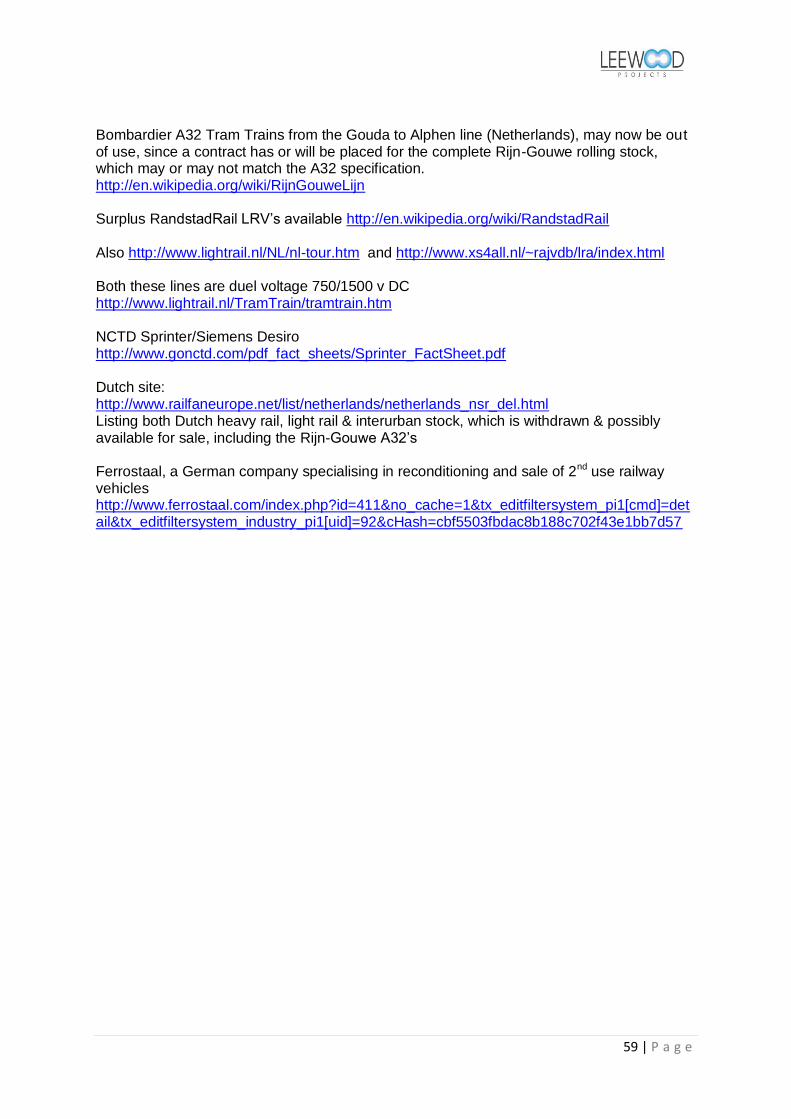
59 | P a g e
Bombardier A32 Tram Trains from the Gouda to Alphen line (Netherlands), may now be out of use, since a contract has or will be placed for the complete Rijn-Gouwe rolling stock, which may or may not match the A32 specification. http://en.wikipedia.org/wiki/RijnGouweLijn Surplus RandstadRail LRV‟s available http://en.wikipedia.org/wiki/RandstadRail Also http://www.lightrail.nl/NL/nl-tour.htm and http://www.xs4all.nl/~rajvdb/lra/index.html Both these lines are duel voltage 750/1500 v DC http://www.lightrail.nl/TramTrain/tramtrain.htm NCTD Sprinter/Siemens Desiro http://www.gonctd.com/pdf_fact_sheets/Sprinter_FactSheet.pdf Dutch site: http://www.railfaneurope.net/list/netherlands/netherlands_nsr_del.html Listing both Dutch heavy rail, light rail & interurban stock, which is withdrawn & possibly available for sale, including the Rijn-Gouwe A32‟s Ferrostaal, a German company specialising in reconditioning and sale of 2nd use railway vehicles http://www.ferrostaal.com/index.php?id=411&no_cache=1&tx_editfiltersystem_pi1[cmd]=detail&tx_editfiltersystem_industry_pi1[uid]=92&cHash=cbf5503fbdac8b188c702f43e1bb7d57

60 | P a g e

61 | P a g e
Appendix E Train-Trams, Zwickau, Riverline & Seetalbahn LRTA June 2006 via Light Rail (UK)
http://www.lightrailuk.com/pdf/axel_kuehn.pdf

62 | P a g e
Appendix F
Electric Traction beyond the Wires
Scott McIntosh April 2009
We discussed at our recent Abbey Line meeting potential ways of using recycled tramway
equipment for use on Community Railways. I pointed out that electrification at 600-750V dc
can be undertaken at lower cost than is initially thought. Nevertheless, we agreed that there
are lines where even low-cost electrification would not be economic and I pointed out that
this did not necessarily preclude the use of recycled tramway equipment.
The photograph above shows a train on the Rotterdamsche Tramweg Mij. (RTM) a series of
interurban light railways to the south west of the city of Rotterdam. The system was an early
user of diesel-mechanical railcars in the 1930s. Damage during the Second World War
meant that the company had to buy, rebuild and operate new vehicles from a number of
sources. Their most ambitions effort was railcar set M1700, created in 1963; this consisted of
two electric trams, previously operated by Deutsche Bundesbahn (DB) on a light rail line in
west Germany, sandwiching a home built generator trailer. This trailer contained a diesel
electric generator, a small supplementary passenger/luggage saloon and two end vestibules
and was styled to match the two tramcars; it fed current through the tramcar controllers to the
existing traction motors on the trams. When the railway was run down and closed in the mid-
late 1960s M1700 was acquired by the Zillertalbahn in Austria in 1966. It was used in
regular service until new railcars arrived in 1984, since then it has formed part of the reserve
fleet, although there have been attempts to return the unit to the Netherlands for use on a
preserved railway.

63 | P a g e
M1700 at Spijkenisse, RTM in 1965 M1700 in use on the ZB Austria
The photograph above shows the general arrangement of the set in use on the Zillertalbahn.
The two ex DB trams are little modified apart from the provision of a power bus line in
replacement for the pantograph. The home-built generator trailer is a remarkably good visual
match; it runs on bogies recovered from a scrapped carriage. The leading vestibule of the
trailer had provision for the fitting of a controller so the set could be run as a two car set if
required – I have no evidence that this was ever done - there is then an entrance vestibule and
a 2-bay seating area, the 3 bays with toplights only, is the motor-generator space.
The advantages of this arrangement are:
the passengers are well insulated from the noise and vibration of the motor-generator
the weight is distributed across a larger number of axles
the tramcars need minimal alteration
the maintenance facility can be a short shed only covering a single car.

64 | P a g e
A little history
These ideas are not new. Heilmann’s experiments in France in the 1890s explored a variety
of electric traction systems, including locomotives and trains where each vehicle was
powered by a through train busbar, fed from a conductor rail or a power station on wheels.
During the prosperous 1920s in Argentina the Buenos Aires Great Southern Railway
(BAGSR) was interested in electrifying their suburban lines around the capital and ordered
two electric multiple units from the UK. The CME of BAGSR was reluctant to init iate full
electrification of the lines around Buenos Aires due to its cost, but believed in the idea of
powered coaching stock, in this case drawing power from a diesel electric generator set
installed in a 'mobile power house'. Accordingly, two 1,200hp mobile power houses,
numbered UE 1 & 2, were delivered in late 1930; each was powered by two Sulzer 8LV28
cylinder engines developing 600hp at 700rpm, powering an Oerlikon main generator.
Traction motors under the coaches were powered by the mobile power houses. They
remained in service at least until 1948.
The success of this experiment led BAGSR to order three 1700hp mobile power houses in
1933. Numbered UE 3, 4 &5 they were used to haul eight coaches. As with UE 1 & 2 the
performance of these three trainsets was impressive, particularly in light of their quick
turnround times at the termini, however for most of their lives they slotted in to steam
diagrams. These mobile power houses remained in service at least until 1959.
London Transport studied these units and one of the options for modernising the
Metropolitan Line under the 1935-40 ‘New Works Programme’ was to introduce electric
multiple units, with mobile power houses being coupled on at Rickmansworth to take the
train beyond the end of the conductor rails to the end of the line. The war and post war
spending restrictions killed the idea and when modernisation was finally approved it was the
far les innovative scheme of taking the conductor rails to Amersham and giving up the rest.
I looked at the concept when examining the possibility of an early tram-train operation in
Blackpool in the early 1990s. The concept was that trams would run ‘on the wire’ to Starr
Gate and then use a diesel generator to run over the Blackpool South – Preston line as far as
Lytham. I looked at two ways of doing this;
Taking one saloon in a Progress Twin-car set out of passenger use and inserting a
diesel generator in its place. The trailers were robustly built in the 1960s and
preliminary discussions with the rolling stock team at Blackpool indicated that the car
could carry a generator set – Blackpool already had some experience of fitting such a
set in the former passenger saloon of a works car. The problem with this approach
was that it would reduce passenger capacity by 25%, the noise and vibration would be
closer to the passengers and the dead weight of the generator set would have to be
carried under the wire from Starr Gate to Fleetwood. (You may care to share these
thoughts with tour Departmental colleagues specifying the IEP)

65 | P a g e
Providing a small fleet of generator trailers. These adopted the concept of the BR
Brake Tender of the 1960’s, in that they would be low enough for the driver of a tram
to look over the tender to see the line ahead. A generator tender would be waiting at
Starr Gate, the tram would couple up to it and it would then be pushed to Lytham as it
provided the traction current. The unit would be towed in the reverse direction and
then dropped off at Starr Gate to await the next tram. The advantage of this system is
that it insulates the passengers from the noise and vibration; there would be no dead
weight to haul ‘under the wires’ and only a limited number of trailers would be
required. This seemed to offer an inexpensive option for extending tram services over
the line.
When diesel locomotive haulage of unfitted goods trains was first introduced, it was considered that
the locomotives would have insufficient brake power to control their trains, so some special "diesel
brake tenders" were introduced. These were heavy wagons (35½ - 37½ tons) fitted with automatic
vacuum brakes. On some BR Regions they were usually pushed by the loco, but on the Southern
Region it was normal practice to pull them.
Experimental operation of a standard Stadtbahn car in Essen coupled to a natural gas – powered
generator trailer. The unit was used to provide demonstration runs in 1999 as part of plans to bring
a non-electrified industrial railway back into service as a light railway

66 | P a g e
Applicability today
The RTM concept could be applied to the provision of a lightweight tram-train for non
electrified lines in the UK. The ex-Berlin Tatra T6 cars were examined for possible use on
the Abbey Line and a description of the car is included in the Phase1 Report. Briefly the car
is a single ended, single sided car, some 15m long. Coupling a pair of these cars back to back
would produce a double-ended set. The front doors could be left in their existing location to
provide driver’s access and emergency detrainment, the rear doors would be plated over and
the redundant equipment used to provide an off-side door. The two centre doors would then
be raised to provide UK platform-level access.
Interior and exterior views of Berlin rebuilt T6 cars
If a pair of these T6 cars was used to sandwich a central generator trailer then a modern
version of the RTM M1700 set would be achieved.
Tatra bogies identical to those in use under the T6 are readily available on the second hand
market at scrap metal prices. The majority of these bogies are motorised, but it is a simple
matter to remove the traction motors, retaining the drive train and cardan shaft friction
brakes. One motor could be left on one truck, thus permitting the motor trailer some limited
manoeuvring capacity, independent of the rest of the train, whilst under limited local control.
An alternative would be to obtain some of the trailer trucks provided under the Tatra
beiwagen trailers supplied to East Germany and Russia. All of these bogies could be
controlled from the motor cars, thus providing a fully-braked train.
The chassis of the generator trailer would be easy to fabricate and the body would only need
to be a lightweight cover for the motor generator unit – unless it is desired to provide some
limited passenger and luggage capacity on the trailer. The motor generator set could be a
normal commercial unit, since many of these are designed to be housed within a normal sea
container there should be few problems in fitting them within the confines of a normal rail
vehicle. It is recommended that thought is given to improving the environmental
performance of the set by introducing a form of ‘hybrid drive’; this could be achieved by
‘floating’ the output of the generator, using a battery, flywheel accumulator or a bank of
super-capacitors. Such an arrangement would allow the unit to accelerate by drawing on the
energy store and to decelerate using the regenerative capacity of the tram – feeding the

67 | P a g e
current into the energy store. Similar arrangements are used on ‘hybrid drive’ road vehicles,
in the Bombardier super-capacitor tram and in the Parry People Mover.
A 3 car set of T6+GT+T6 would be around 45m long and provide a capacity of over 150
passengers (72 seated and 80 standing in the two T6s, plus whatever is proposed for the
generator trailer. The train would have a top speed of around 65kmh and an acceleration of
around 1m/s/s. This performance may not make such a set suitable for longer-distance
interurban work, such as the Penistone Line, but it would certainly be an attractive substitute
for a Pacer on shorter lines (St Ives branch, Stourbridge, Severn Beach, rebuilt Alnwick, etc.)
where there is no need for physical inter-running with main line trains.
Experiment
An experimental set could be built very cheaply; the T6 cars are currently available at low
prices from Germany, spare parts are readily available at scrap metal prices and the diesel
generator set would be a standard commercial product. All that is required is the fabrication
of the diesel generator car body and the modifications to the two T6 cars. If the experiment is
not a success then the diesel generator set can be recovered and sold on, reducing the overall
cost of the experiment.
This experimental set could then be compared with the cost and performance of existing
diesel railcars in the 14X, 15X series – and the Parry cars at Stourbridge.
Whilst the current proposal is for a relatively small train, there is no reason why the concept
could not be enlarged to allow larger articulated trams to be used and the decouplable
generator trailer concept could be used to allow through operation of trams in places such as
Manchester (Manchester – Marple line) or Sheffield (Penistone Line), the concept could also
be expanded to allow the extension of Merseyrail services over the Bidston-Wrexham line –
without the cost of electrification. It is important to note that in the Manchester, Sheffield
and Mersey cases this type of operation could be considered as an intermediate stage in the
development of a full electric network; hybrids could prove the business case and then the
generators redeployed elsewhere once the funds for electrification are available.
SMcI v2 20 April 2009.
Annex A.
Mobile Power Houses in Argentina
In 1929 the Buenos Aires Great Southern Railway (BAGSR) obtained from
Armstrong Whitworth in the UK, two 1,200hp mobile power houses (MPH),
numbered UE 1 & 2, used to power five coaches, three 1st & two 2nd class. Traction
motors under the coaches were powered by the MPH's. One was loaned to the FC
Buenos Aires Pacifico. The CME of BAGSR was reluctant to initiate full
electrification of the lines around Buenos Aires due to its cost, but believed in the idea

68 | P a g e
of powered coaching stock, in this case drawing power from a diesel electric generator
set installed in a 'mobile power house'. These units were semi-permanently coupled to
five coach sets, the end coach being equipped with driving compartments, avoiding
reversals at the busy Buenos Aires terminals. These two locomotives were ordered
just after an order to Beardmore, the first diesel locomotives to work anywhere in South America.
Delivered in late 1930, each was powered by two Sulzer 8LV28 cylinder engines
developing 600hp at 700rpm, powering an Oerlikon main generator & two 136hp
Metropolitan Vickers traction motors - each coach carried two 100hp motors. The
rigid frame supported four fixed axles, two of which were powered with a pony truck
at each end (1-A-2-A-1 arrangement). The components were all received separately in
Argentina, being shipped to the BAGS workshops, where the locomotives were put
together. Because they were semi-permanently coupled to the coaching stock, the
MPH's carried only one driving cab. Locomotive weight was 92 tons, total train weight was 314 tons.
They were most regularly operated out of the Plaza Constitucion terminal to Quilmes,
their acceleration was superior to the regular steam fleet, but the MPU powered trains
generally ran under the steam timings. Occasionally the two sets were combined. In
the early years it was the practice to stop the engines at each station stop, leading to
the engines going through the stop/start cycle over two hundred times a day! They
remained in service at least until 1948.
In 1933 Buenos Aires Great Southern obtained three further 1700hp mobile power houses, 2
x 850hp 8LV34 550rpm, cylinder dimensions 340mm x 400mm, with 8 x 134 hp traction
motors, tractive effort 38,000lb, weight in working order 148.50tons. Numbered UE 3,4 &5
they were used to haul eight coaches, five 1st & three 2nd class. They had an increased top
speed of 70mph but had the same traction motors and reduction gearing as the first two power
houses. The newer machines were also lighter, 132 tons compared to 145 tons. The cost of
the two engine-generator sets and ancillary equipment was GBP16,400.
These three MPH's were direct descendants of the 1930 built UE 1 & 2. Improvements
included the use of two four axle trucks rather than the earlier rigid wheelbase. Each MPH
was comprised of two half units, each containing an engine generator set, though only one
unit had a driving compartment (an A-B unit in American diesel nomenclature). A third
innovation was the use of Messrs J Stone & Co's 'Skefco' roller bearings on all axles, a
welcome fitting in the dry dusty conditions of Argentina.
The Sulzer engines were coupled to Brown Boveri main generators and two English Electric
traction motors on the outer bogie of each half unit. The weight of each double unit was 133
tons, with eight coaches in tow the total train weight was 470 tons. As with UE 1 & 2 the
performance of these three trainsets was impressive, particularly in light of their quick
turnround times at the termini, however for most of their lives they slotted in to steam
diagrams.
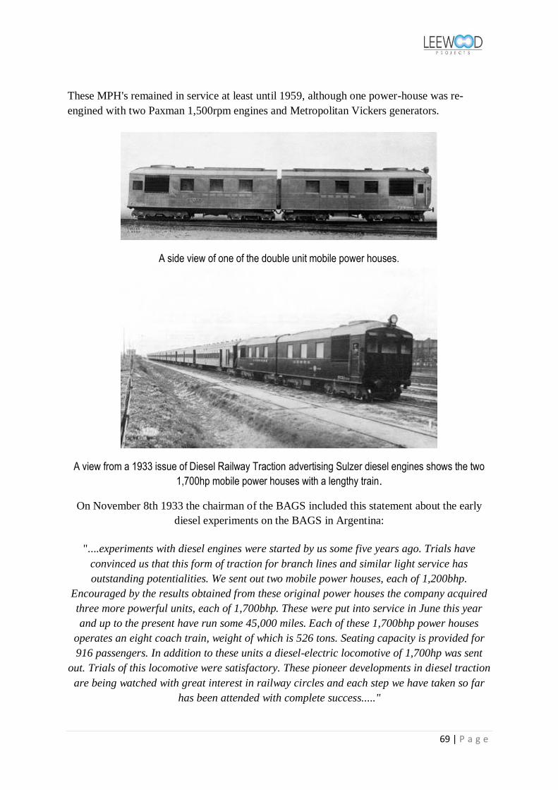
69 | P a g e
These MPH's remained in service at least until 1959, although one power-house was re-
engined with two Paxman 1,500rpm engines and Metropolitan Vickers generators.
A side view of one of the double unit mobile power houses.
A view from a 1933 issue of Diesel Railway Traction advertising Sulzer diesel engines shows the two
1,700hp mobile power houses with a lengthy train.
On November 8th 1933 the chairman of the BAGS included this statement about the early
diesel experiments on the BAGS in Argentina:
"....experiments with diesel engines were started by us some five years ago. Trials have
convinced us that this form of traction for branch lines and similar light service has
outstanding potentialities. We sent out two mobile power houses, each of 1,200bhp.
Encouraged by the results obtained from these original power houses the company acquired
three more powerful units, each of 1,700bhp. These were put into service in June this year
and up to the present have run some 45,000 miles. Each of these 1,700bhp power houses
operates an eight coach train, weight of which is 526 tons. Seating capacity is provided for
916 passengers. In addition to these units a diesel-electric locomotive of 1,700hp was sent
out. Trials of this locomotive were satisfactory. These pioneer developments in diesel traction
are being watched with great interest in railway circles and each step we have taken so far
has been attended with complete success....."

70 | P a g e
Appendix G
Proposed Interurban/Community Rail Station layouts
Mulhouse, Harald Jahn
Montpellier, Malc McDonald
Nantes, David Cockle

71 | P a g e
Appendix H
Background and Report References
i. Diesel Trams – A new way forward, Charles King, Modern Railways March 2007 (Appendix D) ii. Studie Light Rail SCI Cologne 2006 (D) iii. LRT French comparisons - COMPARATIVE PERFORMANCE DATA FROM FRENCH TRAMWAYS
SYSTEMS, SEMALY & FaberMaunsell December 2003 (UK) http://www.pteg.net/NR/rdonlyres/B4142077-F4F3-4650-9012-A65DD91E3B1F/0/LRTfrenchcomparisonsreport.pdf
iv. Making Tracks – Light Rail in England & France, Bertil Hylen +Tim Pharoah, Swedish National Road & Transport Institute (SE)
v. Operation of Trams and Light Rail or Metro Vehicles Over Railtrack Controlled Infrastructure, Railway Group Guidance Note 1999 (UK)
vi. Guidance on Tramways, Office of the Rail Regulator 2006 (UK) vii. What Modern Trams can do for Cities, PTEG 2006 (UK)
http://www.pteg.net/NR/rdonlyres/F37F7FEB-4756-4705-8185-EEEA79F6287E/0/WhatLightRailCanDoforCitiesAppendices_0105.PDF
viii. Rail in City Regions, PTEG 2006 (UK) ix. Cycles on Light Rail, Light Rail Scotland [LRTA] 2004 (UK) x. Technical assessment of Operating Passenger Rail on Interurban Corridors, DRL Solutions
2006 (CA) xi. South of Fraser Transit Plan, TransLink 2006 (CA) xii. Light Rail Transit Association (LRTA) http://www.lrta.org/
xiii. Light Rail (UK) http://www.lightrailuk.com/index.shtml xiv. Light Rail Now, http://www.lightrailnow.org/ xv. Evaluation of the E & N Railway Corridor, BC Ministry of Transport 2009 (CA)
xvi. City of Surrey High Level Review of South of Fraser Community Rail Proposal, UMA Engineering 2007 (CA)
xvii. Calgary light rail transit surface operations and grade-level crossings, D Colquhoun, J. Morrall, J Hubbell Calgary Transit, City of Calgary
xviii. Track Design Handbook for Light Rail Transit - Parsons Brinckerhoff, Quade & Douglas, National Academy Press. TCRP Report 57, and sponsored by the Federal Transit Administration, Transport Research Board & National Research Council (US) 2000
xix. Office of Rail Regulation, Guidance on Tramways, Railway Safety Publication 2 (UK) 2006 xx. Office of Rail Regulation, Tramway Technical Guidance Notes (UK) 2008
xxi. Health & Safety Laboratory, A survey of UK tram and light railway systems relating to the wheel/rail interface (UK) 2006
xxii. Modern Railway Track 2nd Edition, Coenraad Esveld, Delft University of Technology (NL) 2001 xxiii. Canadian Rail Operating Rules, The Railway Association of Canada (CA) 2008 xxiv. City of Edmonton – LRT Design Guidelines (CA) 2009 xxv. Keeping Your Trains on the Track – Strategies for Preventing Derailments, Ensco Inc. |
www.ensco.com (US) 2009 xxvi. Use of Guard/Girder/Restraining rails – Transit Cooperative Research Programme, FTA (US)
2007 xxvii. Regional Transportation District Denver, Light Rail Design Criteria (US) 2005
xxviii. Handbook of Railway Vehicle Dynamics, Edited by Simon Iwnicki CRC Press http://www.crcnetbase.com/isbn/9780849333217 (CA) 2006
xxix. Unofficial Croydon Tramlink web site http://www.croydon-tramlink.co.uk/ xxx. Unofficial Nottingham Express Transit website http://www.nettrams.net/

72 | P a g e
xxxi. Public Transport – an important key to the prosperity of a city, Carmen Hass-Klau http://www.tem.fi/files/19645/Hass_Klau_esitys_ti27052008.pdf
xxxii. Bus or Light Rail: making the right choices, Carmen Hass-Klau, Volker Deutsch. - April 2000
73 | P a g e
List of Tables
Table 1: Proposed Interurban/Community Rail travel time matrix
To be included in Revision No 02

74 | P a g e
Table 2: Schedule of bridge structures
Proposal Ref No
Location CTA/ Hwy Agency
Designation
Type Construction Crossing Comments
Highway /Road
River/ stream
Railway
B10-01 Airport Rd Chilliwack
_ Rail Over
Steel box girder _ Vedder _ Single span
B10-02 Chilliwack Highway 1 Rail Over
Steel box girder TCH & Luckakuck Way
_ _ 3-span
B10-03 Yarrow _ Rail Over
Steel bowstring _ Vedder _ 2-span
B10-04 Arnold _ Rail Over
Timber deck & beam & pier
Marion Road
_ _ Single span
B10-05 Arnold _ Rail Over
Timber deck & beam & pier
Arnold Road
_ _ Single span
B10-06 Upper Sumas
_ Rail Over
Timber deck & beam & pier
Bowman Road
_ _ Single span
B10-07 Upper Sumas
_ Rail Over
Timber deck & beam & pier
Un-classified
Un-named
_ Single span
B10-08 Upper Sumas
_ Rail Over
Timber deck & beam & pier
Lamson Road
_ _ Single span
B10-09 Upper Sumas
_ Rail Over
Timber deck & beam & pier
Maher Rd _ _ Single span
B10-10 Abbotsford Highway 1 Rail Under
PCC beam & Insitu RC deck
Trans-Canada Hwy
_ _ Single span
B10-11 Abbotsford Highway 11 Rail Under
PCC beam & Insitu-RC piers & deck
South Fraser Hwy
_ _ 4- span
B10-12 Abbotsford _ Rail Under
PCC beam & Insitu RC deck
Maclure Road
_ _ Single span
B10-13 Abbotsford _ grade Diamond crossing
_ _ Clayburn Rd
CPR
B10-14 Gifford [Glenmore Road]
_ Rail Over
Steel box girder _ Un-named
_ Single span
B10-15 Sperling 264th street
Rail Under
Timber trestle, steel beams Insitu RC deck
County Line Road
_ _ Single span
B10-16 Livingstone /Trinity Western Uni
Highway 1 Rail Over
Insitu RC walls & deck
Trans-Canada Hwy
_ _ Twin Single span
B10-17 Langley 204a St Rail Under
PCC beam & Insitu RC piers & deck
Duncan Way
_ _ Multi span viaduct
B10-18 Cloverdale Pacific Highway 15
Rail Under
PCC beam & Insitu RC piers & deck
176th Street
Cloverdale Bypass
B10-19 Surrey 56
th
Ave 10
Rail Over
Steel trestle _ Pit? _ Single span

75 | P a g e
Table 3: Schedule of grade highway crossings
Proposal Ref No
Location Hwy/Avenue/Street Ref
Hwy/Avenue/St Name
Existing Grade Crossing Type Interurban Up-grade
Comment
Gate & Light Protected
Light & Bell Protected
Stop Sign Protected
GLP ¦ LBP
G10-01 Chilliwack _ 8898 Young Rd
√ _ _ _
G10-02 Chilliwack _ 45822 Hocking Ave
_ _ √ LBP
G10-03 Chilliwack _ 45722 Airport Rd
_ _ √ LBP
G10-04 Chilliwack _ 45786 Knight Rd
_ _ √ LBP
G10-05 Chilliwack _ 45786 Web Ave
√ _ _
G10-06 Chilliwack _ 7140 Vedder Rd
_ √ _ GLP
G10-07 Chilliwack _ Spruce Drive _ _ √ LBP
G10-08 Chilliwack _ 6974 Evans Rd
_ √ _ GLP
G10-09 Chilliwack 6520 Unsworth Rd
_ _ √ _
G10-10 Chilliwack _ 44440 S. Sumas Rd
_ _ √ LBP
G10-11 Chilliwack _ Lickman Rd _ _ √? X-type not known
G10-12 Chilliwack _ Keith Wilson Rd
_ _ √? X-type not known
G10-13 Chilliwack _ McLaren Drive?
_ _ √? X-type not known
G10-14 Chilliwack _ Lumsden Road
_ _ √? X-type not known
G10-15 Chilliwack _ 42762 Yarrow Central Rd
_ _ √ LBP
G10-16 Chilliwack _ Wilson Road _ _ √? X-type not known
G10-17 Chilliwack _ Belrose Road _ _ √? X-type not known
G10-18 Abbotsford _ Old Yale Rd _ _ √? X-type not known
G10-19 Abbotsford _ 680 Whatcom Rd
_ _ √ _
G10-20 Abbotsford _ Kenny Rd
_ _ √ _
G10-21 Abbotsford _ Angus Campbell Rd
_ _ √ _
G10-22 Abbotsford _ 34888 Boundary Rd
_ _ √ _
G10-23 Abbotsford 9 Cherry St
√ _ _ _

76 | P a g e
Proposal Ref No
Location Hwy/Avenue/Street Ref
Hwy/Avenue/St Name
Existing Grade Crossing Type Interurban Up-grade
Comment
Gate & Light Protected
Light & Bell Protected
Stop Sign Protected
GLP ¦ LBP
G10-24 Abbotsford 11 Sumas Way
√ _ _ _
G10-25 Abbotsford 4th Avenue
_ _ √ _
G10-26 Abbotsford _ 34540 Vye Rd
_ √ _ _
G10-27 Abbotsford _ Marshall Rd
√ _ _ _
G10-28 Abbotsford _ 33842 Essendene Ave
√ _ _ _
G10-29 Abbotsford _
33813 George Ferguson Way
√ _ _ _
G10-30 Abbotsford _ 2931 McCallum Rd
_ √ _ _
G10-31 Abbotsford _ Maclure Rd
√ _ _ _
G10-32 Abbotsford _ 33618 Valley Rd
_ _ √ _
G10-33 Abbotsford _ 33880 Clayburn Rd
_ _ √ _
G10-34 Abbotsford _ 33140 Townshipline Rd
_ _ √ _
G10-35 Abbotsford _ 5142 Gladwin Rd
_ _ √ _
G10-36 Abbotsford _ 5336 Glenmore Rd
_ _ √ _
G10-37 Abbotsford _ 31421 Harris Rd
_ _ √ _
G10-38 Abbotsford _ 30974 N Burges Ave
_ _ √ _
G10-39 Abbotsford _ 5895 Mt Lehman Rd
_ _ √ _
G10-40 Abbotsford _ 5658 Ross Rd
_ _ √ _
G10-41 Abbotsford _ Bradner Rd
_ _ √ _
G10-42 Abbotsford _ 5490 Rand St
_ _ √ _
G10-43 Abbotsford _ 56th Avenue
_ _ √ _
G10-44 Abbotsford 272 St 5948 Jackman Rd
_ _ √ _

77 | P a g e
Proposal Ref No
Location Hwy/Avenue/Street Ref
Hwy/Avenue/St Name
Existing Grade Crossing Type Interurban Up-grade
Comment
Gate & Light Protected
Light & Bell Protected
Stop Sign Protected
GLP ¦ LBP
G10-45 Abbotsford 26700 62nd Ave
_ _ _ √ _
G10-46 Abbotsford 26306 64th Ave
_ --- --- √ ---
G10-47 Abbotsford 258th St _
_ _ √ _
G10-48 Abbotsford 6900 256th St
_ _ _ √ _
G10-49 Langley 6762 248th St
_ _ _ √ _
G10-50 Langley 7060 240th St
_ _ _ √ _
G10-51 Langley 23702 72nd Ave
_ _ _ √ _
G10-52 Langley 7588 232nd St
_ √ _ _ _
G10-53 Langley _ 7600 Glover Rd
√ _ _ _
G10-54 Langley 216th St _
√ _ _ _
G10-55 Langley _ 21482 Smith Crescent
_ _ √ _
G10-56 Langley _ Crush Crescent
√ _ _ _
G10-57 Langley _
21150 Worrell Crescent
√ _ _ _
G10-58 Langley _
20780 Mufford Crescent
√ _ _ _
G10-59 Langley 10
20698 Langley Bypass
√ _ _ _
G10-60 Langley
5981 200th St
_ √ _ _ _
G10-61 Langley 1A
19879 Fraser Highway
√ _ _ _
G10-62 Langley 56
th Ave
19462 Langley Bypass
√ _ _ _
G10-63 Langley 192nd St _ √ _ _ _
G10-64 Langley 188th St _ _ _ √ _
G10-65 Langley 184th St _ _ _ √ _
G10-66 Surrey 5566 168th
St _ √ _ _ _

78 | P a g e
Proposal Ref No
Location Hwy/Avenue/Street Ref
Hwy/Avenue/St Name
Existing Grade Crossing Type Interurban Up-grade
Comment
Gate & Light Protected
Light & Bell Protected
Stop Sign Protected
GLP ¦ LBP
G10-67 Surrey 10 56
th Ave/164
th
St √ _ _ _
Old McLellan Rd
G10-68 Surrey 6010 156th
St _ _ _ √ _
G10-69 Surrey 152nd St _ √ _ _ _
G10-70 Surrey 14851 64th
Ave _ √ _ _ _
G10-71 Surrey 6442 148th
St _ √ _ _ _
G10-72 Surrey 6692 144th
St _ √ _ _ _
G10-73 Surrey 138th St _ _ √ _ GLP
G10-74 Surrey 99A 7046 King
George Hwy _ √ _ GLP
G10-75 Surrey 13530
72nd Ave _ _ √ _ GLP
G10-76 Surrey 13236 76th
Ave _ _ √ _ GLP
G10-77 Surrey 7560
132nd St _ _ √ _ _
G10-78 Surrey 12898 80th
Ave _ _ √ _ _
G10-79 Surrey 8116 128
th
St 128
th/82
nd Ave
intersection √ _ _ _
G10-80 Surrey _ 12090 Nordel
Way √ _ _ _
G10-81 Surrey 12066 88th
Ave _ √ _ _ _
G10-82 Surrey 120th St Scott Road _ √ _ GLP
G10-83 Surrey 11944
92nd Ave _ _ √ _ _
G10-84 Surrey 11884 96th
Ave _ _ _ √ _
G10-85 Surrey 9880 120th
St _ √ _ _ _
G10-86 Surrey 12422
104th Ave _ _ √ _ _
G10-87 Surrey 106th Ave & 125a St
_ _ _ √ _
G10-88 Surrey - 12538 Old Yale Road
_ √ _ _
G10-89 Surrey 12566
110th St _ _ _ _ GLP
New Grade Crossing