Embed Size (px)
Citation preview

GE159 Plastics AvenuePittsfield, MA 01201
. ; ' • USA
Transmitted via Electronic Mail and Overnight Courier
October 31, 2005
Mr. William P. Lovely, Jr.U.S. Environmental Protection AgencyEPA New EnglandOne Congress Street, Suite 1100Boston, Massachusetts 02114-2023
Re: GE-Pittsfield/Housatonic River SiteNewell Street Area II (GECD450)Proposal for Test Trenching Activities
Dear Mr. Lovely:
A. Introduction
In a September 6, 2005 letter to the U.S. Environmental Protection Agency (EPA), the General ElectricCompany (GE) proposed to conduct a geophysical survey at portions of the Newell Street Area IIRemoval Action Area (RAA) located in Pittsfield, Massachusetts. GE's proposal was prompted by thediscovery of buried drums during soil remediation activities at this RAA, and was developed to assessother areas where drums may potentially be present below the ground surface. The proposed activitiesincluded the use of three different geophysical techniques within the area where the drums were initiallyencountered (i.e., Parcel J9-23-8, owned by the Western Massachusetts Electric Company) - namely,magnetometer and electromagnetic (EM) methods and ground-penetrating radar (GPR). EPAconditionally approved GE's proposal in a letter dated September 14, 2005, and required, among otherthings, that the area to be subject to the survey be extended to include those areas west of Parcel J9-23-8(other than Parcel 19-7-1) where soil excavation activities were planned.
Following EPA approval of GE's proposal, geophysical survey activities were initiated and werecompleted on October 11, 2005. Consistent with EPA's conditional approval letter, GE consulted withEPA at various times during the survey to discuss the status of on-site activities, preliminary findings, andthe scope of subsequent survey activities.
One of the anticipated outcomes of the geophysical survey was the need to conduct intrusive investigationactivities within the surveyed area to further assess the nature of detected subsurface anomalies.Specifically, as proposed by GE and reiterated in EPA's conditional approval letter, if the results of thegeophysical survey indicated the presence of subsurface anomalies that could potentially constitute burieddrums, GE would discuss with EPA the need for and scope of subsequent intrusive investigations beyondthe soil remediation activities already approved by EPA, As has been previously communicated to EPA,and as summarized in this letter, the results of the geophysical survey indicate that non-native, metallicobjects (i.e., anomalies) are present in the subsurface, possibly including buried drums. As such, GE hasdiscussed with EPA the performance of an intrusive test trenching program to further assess the nature ofthe detected anomalies.

Mr. William P. Lovely, Jr.October 31, 2005
Page 2 of 5
This letter provides GE's proposed scope of test trenching activities for EPA review and approval. Insupport of this proposal, this letter also provides a brief overview of the completed geophysical surveyactivities; a more detailed summary of these activities will be provided in a future submittal, as discussedin Part D of this letter.
Although GE does not believe that the activities proposed herein are required by the Consent Decree (CD)for the GE-Pittsfield/Housatonic River Site, GE proposes to conduct these activities pursuant to the CD.In doing so, GE reserves the right to contend that any additional response actions at this RAA that gobeyond those specified in the Statement of Work for Removal Actions Outside the River and in the workplans that EPA approved for this RAA prior to the commencement of the remediation are not required bythe CD, and to contest any future directive to conduct such response actions.
B. Summary of Geophysical Survey Activities
This section presents an overview of the geophysical surveys that were conducted at Newell Street Area IIbetween September 15 and October 11, 2005. In the interests of expediting the preparation of thisproposal, only a brief summary of the completed survey activities is presented herein, including a generaldescription of the survey techniques that were used, with references to the appropriate figure thatillustrates the general scope and findings of each of the surveys. GE will provide a more detailedsummary of the completed geophysical surveys, as well as a summary of the test trenching programproposed herein, in a Subsurface Investigation Summary Report, as discussed in Part D of this letter.
The recent survey activities conducted at Newell Street Area II used multiple geophysical techniques inan effort to identify areas where buried drums and/or other objects/subsurface features may be present.This multi-instrument survey approach produced several lines of evidence that can account for potentialsources of interferences (e.g., power lines, fences, etc.) and limitations associated with the individualtechniques. The geophysical methods included a combination of EM-61 and magnetometer surveys toassess the potential presence of metallic objects in the subsurface, and GPR to provide radar images of thesubsurface anomalies identified by the EM-61 and magnetometer surveys. Additional discussion of eachof these techniques is provided below.
• Electromagnetic Survey - The EM survey was performed to detect subsurface metallic objectswithout significant interference from surface features (e.g., buildings, power lines, and fences). Theoperation of this instrument is based on the emission, or pulse, of a time-varying magnetic fieldgenerated from an alternating current at the transmitter. After each pulse, secondary electromagneticfields are induced briefly into the earth. Between each pulse, the equipment pauses until the responsefrom the earth dissipates, and then measures the prolonged response received from buried metallicobjects. The EM survey was completed from September 15 to September 19, 2005, and wasperformed using a Geonics EM-61 MK2 equipped with a digital data logger and a Trimble AG-132Global Positioning System (GPS). Data were collected using both manual and survey wheel modesof collection due to the uneven areas at the site resulting from the active soil excavation work. Figure1 illustrates the findings of this EM survey.
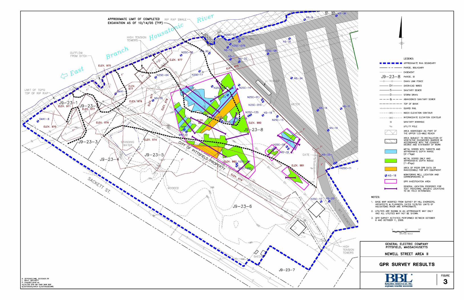
• Magnetometer Survey - The magnetometer survey was performed to detect buried ferromagneticobjects. The magnetometer operates on the principle of measuring the earth's magnetic field anddeviations in this field caused by the presence of ferromagnetic objects. The intensity and variationcaused by such objects are related to the depth and mass of the buried object and to a lesser degree theorientation of the object. The magnetometer survey was performed on September 20, 2005, using aGeometries G-858 portable cesium magnetometer equipped with a Trimble AG-132 GPS.Magnetometer readings were collected at one second intervals along the survey lines established forthe site survey. Figure 2 illustrates the findings of this magnetometer survey.

Mr. William P. Lovely, Jr.October 31, 2005
Page 3 of 5
• Ground Penetrating Radar - Based on the results of the EM and magnetometer surveys, GEidentified four target areas within the overall survey areas as appropriate for the performance of theGPR survey to further assess anomalies identified during the EM and magnetometer surveys. Thosespecific target areas for the GPR survey were presented to EPA and are shown on Figures 1 through3. The GPR equipment transmits high frequency electromagnetic waves into the ground and detectsthe energy reflected back to the surface. Energy is reflected along subsurface interfaces that possessdifferent electrical properties. Reflections typically occur at lithologic contacts or when theelectromagnetic waves encounter subsurface materials having high electrical contrasts, includingmetal objects such as underground storage tanks (USTs), drums, and utility pipes. These reflectionsare detected by the antenna and processed into an electrical signal, which can be used to image thesubsurface feature. The GPR survey was performed from October 6 to October 11, 2005, using aGeophysical Survey Systems, Inc., SIR-2000 system and a 200 megahertz antenna. The four targetareas were surveyed, and GPR data were collected continuously along each survey line. Figure 3illustrates the findings of this GPR survey.
C. Proposed Test Trenching Program
Based on the results of the geophysical surveys, as well as recent input provided by EPA, GE hasdeveloped an intrusive test trenching program for EPA review and approval. The overall purposes of theproposed program are to better understand the nature of the detected subsurface anomalies identified bythe surveys and to determine whether such anomalies are indicative of buried drums. Upon completion ofthis program, further evaluations will be conducted by GE and discussed with EPA and the MassachusettsDepartment of Environmental Protection (MDEP) to determine what further actions, if any, areappropriate. This section describes the proposed locations for test trenching activities and the proceduresthat GE will implement during the performance of this program.
Figures 1, 2, and 3 (which illustrate the results of the EM, magnetometer, and GPR surveys, respectively)identify, on each figure, the proposed test trench locations. In total, the proposed test trenching programincludes approximately 800 linear feet of test trench. The location of each completed trench will besurveyed.
The performance of the test trenching activities will be conducted in accordance with the proceduresdescribed below. Should it be necessary to significantly modify those procedures, GE will consult withEPA.
• The work will be performed by GE's existing Remediation Contractor. All existing site monitoringand control activities performed by GE or its contractors will be maintained, including site security,health and safety provisions, air monitoring, erosion control, equipment cleaning, provisions forhandling drums, etc.
• The width and depth of each test trench will vary depending on the specific conditions that areencountered/observed. The depth of the trench will consider equipment access/capabilities, thepresence of the water table, and side-slope stability considerations. Based on these factors, amaximum trench depth of 6 to 10 feet is anticipated. The width of the trench will, to the extentpossible, correspond to the width of the excavation equipment.

Mr. William P. Lovely, Jr.October 31, 2005
Page 4 of5
• The subsurface conditions associated with each trench will be assessed through visual observation ofthe excavated materials and (to the extent possible) direct observation of the trench sidewalls and endwalls. The test trench excavations will occur in depth increments of approximately 2 to 3 feet inthickness. This will facilitate the observation of the trench sidewalls and end walls, allow time forrecordkeeping and on-site review/discussion as needed, and the controlled handling of excavatedsoils, as discussed below.
• For each test trench, several visual observations and field measurements will be collected andrecorded. These observations and measurements will be made from outside the trench, as nopersonnel will be permitted to access the trench. The observations and measurements to be made andrecorded will consist of the following:
Date, start/stop time, trench ID, equipment used, etc.;
Physical dimensions of completed trench, e.g., overall length, width(s), depth(s), etc.;
Presence of groundwater, if encountered;
Visual observations of the native and non-native materials that are excavated from each trench,including type, approximate in-situ location/depth, and related observations;
To the extent that it is possible and safe to do so from outside the trench, visual observations ofthe sidewalls and end walls (representing the in-situ materials);
Observations of any drums, capacitors, or other similar electrical equipment encountered,including condition, specific location within the trench (which will be documented), depth(relative to ground surface or other benchmark), quantity (as appropriate), etc.; and
Observations of other objects or features (including locations and depths) that could contribute toand/or explain the nature of the anomalies identified during the geophysical surveys.
• As the test trench activities proceed, the Remediation Contractor will excavate and handle the trenchmaterials based on the type of materials that are encountered. As part of this activity, one or morecontrolled staging areas will be established to facilitate the test trench operations. The locations ofthe staging areas will be determined in the field.
• If any intact drums or capacitors, drum/capacitor fragments, or other large metallic debris areencountered within the test trenches depicted on Figures 1 through 3, these items will be removed.Consistent with the procedures already in place at this RAA, these materials will be separately stagedfor disposition either at the Building 71 On-Plant Consolidation Area (OPCA) or at an off-sitedisposal facility. Intact drums potentially containing liquids will be placed directly into overpackdrums for subsequent characterization testing, while the other types of material will be staged onpolyethylene sheeting for additional processing and handling.
• To minimize the potential for odors and dust and for site safety reasons, completed sections of the testtrench will be backfilled as soon as practicable after excavation of the trench, performance of thenecessary visual observations, and removal of the items noted above, if any. With the exception ofintact drums and capacitors, drum/capacitor fragments, and other unsuitable materials (e.g., largemetallic debris, appliances, etc.), the soil and other fill materials excavated from the test trenches willbe used as trench backfill material. In removing and replacing these materials, the RemediationContractor will excavate, handle, stage, and backfill the materials in such a manner that the excavatedmaterials are returned to the same depth increments from which they were removed (i.e., last-out/first-in approach for excavating/backfilling materials).

Mr. William P. Lovely, Jr.October 31, 2005
Page 5 of5
• As needed and to possibly compensate for materials that are not suitable for use as backfill, cleanbackfill materials will be placed to achieve a stable grade at the top of each trench location.
D. Schedule and Reporting
Following EPA approval of the proposed test trenching activities, GE will coordinate with EPA, MDEP,and GE's Remediation Contractor to schedule and implement the proposed activities. The anticipatedduration of the trenching program is unknown. However, during the course of the test trenching, GEanticipates that EPA will actively monitor the progression of the trenching efforts. Consistent with EPA'sSeptember 14, 2005 conditional approval of GE's proposed geophysical survey, GE will discuss withEPA in an expedited manner the results of the test trenching program, as well as subsequent activities (ifany) in this area.
In addition, as previously indicated, GE proposes to prepare a Subsurface Investigation Summary Reportfollowing the completion of the test trenching program. That report will include a summary of thecompleted geophysical surveys and test trenching program, including the supporting materials and datathat were generated by these activities (e.g., instrument data, test trench logs, figures, etc.). GE proposesto submit that report within 30 days following completion of the test trenching program.
Please contact me if you have questions or comments concerning GE's proposed test trenching program.
Sincerely,
Andrew T. Silfer, P.E.GE Project Coordinator
AttachmentsV:\GE_Phtsfleld_CD__Newell_St__Area_n\CoiTespondmce\65052196DOC
cc: Dean Tagliaferro, EPATim Conway, EPAHolly Inglis, EPARose Howell, EPA*K.C. Mitkevicius, USACELinda Palmieri, WestonAnna Symington, MDEP*Robert Bell, MDEP*Susan Steenstrup, MDEP (2 copies)Thomas Angus, MDEP*Mayor James Ruberto, City of PittsfieldPittsfield Commissioner of Public HealthNancy E. Harper, MA AG*
Dale Young, MA EOEA*Paul Dowd, Western Mass. Electric Co.Michael Carroll, GERichard Gates, GERod McLaren, GEJames Nuss, BBLJames Bieke, Goodwin ProcterSamuel Gutter, Sidley Austin Brown & WoodJohn Ciampa, SPECTRAPublic Information RepositoriesGE Internal Repositories
(* without attachment)

APPROXIMATE LIMIT OF COMPLETED RIP RAP SWALE
EXCAVATION AS OF 1 0 / 1 4 / 0 5 (TYP)
HIGH TENSIONTOWERS
OUTFLOWFROM DITCH—\
OMALY DUE TOSANITARY SEWER LINE
LIMIT OF TOPO
TOP OF RIP RAP
RESPONSE(MILLIVOLTS)
X: 20705X01.DWG, 20705X01.TIFL: 0N=*. OFF=REF*P: PAGE5ET/5YR-DL10/31/05 SYR-B5-DMW DMW BGPN/20705003/AREA-II/20705C02.DWG
900
700
500
300
100
0
-100
-300
-500
-700
-900
-1100
LEGEND:
APPROXIMATE RAA BOUNDARY
PARCEL BOUNDARY
EASEMENT
J 9 - 2 3 - 8 PARCEL IDo o CHAIN LINK FENCE
OH OVERHEAD WIRES
S SANITARY SEWER
D STORM DRAIN
-5- ABANDONED SANITARY SEWER
TOP OF BANK
^ ^ ^ ^ ^ ^ ^ GUARD RAIL
980 INDEX ELEVATION CONTOUR
982 INTERMEDIATE ELEVATION CONTOUR
© SANITARY MANHOLE
^ UTILITY POLE
PAVED (ASPHALT/CONCRETE)
I / \ / AREA ADDRESSED AS PART OFY •/ THE UPPER 1/2-MILE REACH
AREA SUBJECT TO INSTALLATION OFk \ \ | VEGETATIVE ENGINEERED BARRIER INl \ \ N ACCORDANCE WITH THE CONSENT
DECREE AND STATEMENT OF WORK
©NS-18 MONITORING WELL LOCATION ANDCORRESPONDING ID
GPR INVESTIGATION AREA
GENERAL LOCATION PROPOSED FORTEST TRENCHING. SPECIFIC LOCATIONSTO BE FIELD DETERMINED.
NOTES:
1. BASE MAP MODIFIED FROM SURVEY BY HILL ENGINEERS,ARCHITECTS & PLANNERS, DATED 1 2 / 9 / 0 3 . LIMITS OFHOUSATONIC RIVER ARE APPROXIMATE.
2. UTILITIES ARE SHOWN IN AN APPROXIMATE WAY ONLYAND ALL UTILITIES MAY NOT BE SHOWN.
3. EM61 SURVEY ACTIVITIES PERFORMED BETWEENSEPTEMBER 15 AND SEPTEMBER 19, 2005.
GENERAL ELECTRIC COMPANYPITTSFIELD, MASSACHUSETTS
NEWELL STREET AREA II
EM61 SURVEY - CHANNEL DRESPONSE (DIFFERENTIAL)
BBLBLASLAND, BOUCK & LEE, INC.&nQln&0fs, scl&ntists, oconom/sfs
FIGURE
1

APPROXIMATE LIMIT OF COMPLETED RIP RAP SWALE^EXCAVATION AS OF 10/14/05 (TYP)— \
ANOMALY DUE TO HIGH - iTENSION TOWERS \
HIGH TENSION ' [ Q
OUTFLOWFROM DITCH
TOTAL FIELD VALUE (nT)
ANOMALY DUE TOSANITARY SEWER LINE
LIMIT OF TOPOTOP OF RIP
X: 20705X01.DWG, 20705X01.TIFL: 0N=*. OFF=REF*P: PAGE5ET/SYR-DL2B110/31/05 SYR-B5-DMW DMW BGPN/207050D3/AREA-II/20705C01.DWG
J9-23-8
• O H -
-s-
LEGEND:
APPROXIMATE RAA BOUNDARY
PARCEL BOUNDARY
EASEMENT
PARCEL ID
CHAIN LINK FENCE
OVERHEAD WIRES
SANITARY SEWER
STORM DRAIN
ABANDONED SANITARY SEWER
TOP OF BANK
GUARD RAIL
INDEX ELEVATION CONTOUR
INTERMEDIATE ELEVATION CONTOUR
SANITARY MANHOLE
UTILITY POLE
PAVED (ASPHALT/CONCRETE)
AREA ADDRESSED AS PART OF THEUPPER 1/2-MILE REACH
AREA SUBJECT TO INSTALLATION OFVEGETATIVE ENGINEERED BARRIER INACCORDANCE WITH THE CONSENTDECREE AND STATEMENT OF WORK
MONITORING WELL LOCATION ANDCORRESPONDING ID
GPR INVESTIGATION AREA
GENERAL LOCATION PROPOSED FORTEST TRENCHING. SPECIFIC LOCATIONSTO BE FIELD DETERMINED.
NOTES:
1. BASE MAP MODIFIED FROM SURVEY BY HILL ENGINEERS,ARCHITECTS & PLANNERS, DATED 1 2 / 9 / 0 3 . LIMITS OFHOUSATONIC RIVER ARE APPROXIMATE.
2. UTILITIES ARE SHOWN IN AN APPROXIMATE WAY ONLYAND ALL UTILITIES MAY NOT BE SHOWN.
3. MAGNETOMETER SURVEY ACTIVITIES PERFORMED ONSEPTEMBER 20, 2005.
30' 60 '
GRAPHIC SCALE
© NS-18
GENERAL ELECTRIC COMPANYPITTSFIELD, MASSACHUSETTS
NEWELL STREET AREA II
MAGNETOMETER SURVEY -TOTAL FIELD CONTOUR MAP
BBLBLASLAND, BOUCK & LEE, INC.&nQln&0fs, scl&ntists, oconom/sfs
FIGURE
APPROXIMATE LIMIT OF COMPLETED RIP RAP SWALE^EXCAVATION AS OF 10/14/05 ( T Y P ) \
ELEV. 971 V J 9 - 2 3 - -
/J9-23-6
X: 20705X01.DWG, 20705X01.TIFL: 0N=*. OFF=REF*P: PAGE5ET/5YR-DL10/31/05 SYR-B5-DUW DMW BGPN/20705003/AREA-II/20705C03.DWG
LEGEND:
APPROXIMATE RAA BOUNDARY
PARCEL BOUNDARY
EASEMENT
J9-23-8 PARCEL IDo o CHAIN LINK FENCE
OH OVERHEAD WIRES
S SANITARY SEWER
D STORM DRAIN
-S- ABANDONED SANITARY SEWER
TOP OF BANK
^ " " " " " " ^ GUARD RAIL
980 INDEX ELEVATION CONTOUR
982 INTERMEDIATE ELEVATION CONTOUR
® SANITARY MANHOLE
• a UTILITY POLE
1/ \ A AREA ADDRESSED AS PART OFV Y THE UPPER 1/2-MILE REACH
AREA SUBJECT TO INSTALLATION OFk \ \ | VEGETATIVE ENGINEERED BARRIER INl \ \ N ACCORDANCE WITH THE CONSENT
DECREE AND STATEMENT OF WORK
. . METAL DEBRIS WITH TARGETS ANDAPPROXIMATE DEPTH RANGE(2 -7 -bgs )
. . METAL DEBRIS ONLY ANDAPPROXIMATE DEPTH RANGE(1'-8 'bgs)
I 1 AREA OF POOR GPR DATA ORI | INACCESSIBLE FOR GPR EQUIPMENT
» U c _ 1 H MONITORING WELL LOCATION AND
1 ° CORRESPONDING ID
GPR INVESTIGATION AREA
GENERAL LOCATION PROPOSED FOR1̂ —^—I TEST TRENCHING. SPECIFIC LOCATIONS
TO BE FIELD DETERMINED.NOTES:
1. BASE MAP MODIFIED FROM SURVEY BY HILL ENGINEERS,ARCHITECTS & PLANNERS, DATED 1 2 / 9 / 0 3 . LIMITS OFHOUSATONIC RIVER ARE APPROXIMATE.
2. UTILITIES ARE SHOWN IN AN APPROXIMATE WAY ONLYAND ALL UTILITIES MAY NOT BE SHOWN.
3. GPR SURVEY ACTIVITIES PERFORMED BETWEEN OCTOBER6 AND OCTOBER 11, 2005.
GRAPHIC SCALE
GENERAL ELECTRIC COMPANYPITTSFIELD, MASSACHUSETTS
NEWELL STREET AREA II
GPR SURVEY RESULTS
BBLBLASLAND, BOUCK & LEE, INC.6nQln&0fs, sc/snf/sfs, oconom/sfs
FIGURE