Embed Size (px)
Citation preview
Proposal for the 252Cf source upgrade to the ATLAS facility
Physics Division, Argonne National Laboratory
Contact persons: Guy Savard, Richard Pardo
February 22, 2005
Abstract
Beams of accelerated exotic neutron-rich nuclei allow access to little known regions of
the nuclear landscape that are important both structurally and for r-process
nucleosynthesis. We propose to increase the radioactive beam capabilities of the ATLAS
accelerator facility by the installation of a new source of ions to provide beams of short-
lived neutron-rich isotopes. These isotopes will be obtained from a 1 Ci 252Cf fission
source located in a large gas catcher from which the radioactive ions will be extracted
and transferred to an ECR ion source for charge breeding before acceleration in the
ATLAS superconducting linac. The technique is fast, universal and highly efficient.
It will provide accelerated neutron-rich beam intensities of up to 7 · 105 ions per second
on target at energies that are difficult to access at other facilities. This upgrade will
enhance the reach of ATLAS and offer world-unique capabilities to study neutron-rich
nuclei. It will also help advance technologies critical for the RIA facility.

I. Summary
Low-energy nuclear physics is at a very exciting time. The field, through both
experimental and theoretical advances, has developed an “ab initio” understanding of the
lightest nuclei starting from the nucleon-nucleon and 3-body forces, and an effective
understanding of the heavier nuclei easily accessible in the laboratory. There is also a
clear path to join these approaches from which an unified theory of most nuclei will
emerge. Facilities, such as ATLAS, will play an important role in this quest. There are
also indications from the region of very neutron-rich nuclei that the effective interactions
are modified. This is the new frontier for low energy nuclear physics, where new
phenomena are expected and a deeper understanding of so far untractable degrees of
freedom will emerge.
The research interests in the field are moving in this direction but will have to await RIA
to reach the most remote regions. In the meantime, progress can be made with more
limited facilities that will guide the way and help develop the techniques and expertise
necessary to explore neutron-rich nuclei. Some neutron-rich radioactive beam
capabilities exist at present facilities, but some of the requirements for a number of
important studies are not met. We have taken a critical look at these requirements for
basic classes of experiments and developed an upgrade plan for ATLAS that will address
these issues. The plan is based on ion source and ion extraction techniques developed for
RIA to be used in conjunction with a strong californium fission source. When combined
with the high efficiency post-acceleration that ATLAS can provide, this will produce
2
beams of sufficient variety and intensity to address the core scientific questions. The
upgrade plan is described in the following pages where it is demonstrated that the new
technologies allow the important requirements to be met at a modest cost. The project is
highly complementary to other efforts worldwide since the fission fragment distribution
from californium is different from that from uranium and production is focused on nuclei
that cannot be extracted by any of the present ISOL facilities, including HRIBF and
ISAC, nor future ones, such as MAFF and SPIRAL2. It is a timely opportunity that has
great physics and technical synergy with RIA and will help develop a map to guide the
community in its future quests.
3

II. Table of Contents
I. Summary 2
II. Table of Contents 4
III. Scientific Justification 6
A. Single-particle structure in the vicinity of magic nuclei 8
B. Pairing interaction in neutron rich nuclei 11
C. Gamma ray studies of neutron rich nuclei 13
D. Nuclear properties along the r-process path 17
E. Laser spectroscopy of neutron-rich nuclei 20
F. Stockpile stewardship 22
IV. Conceptual Overview 23
V. Technical Description
A. Source of radioactive isotopes
B. Gas catcher and degrader
C. Transport cask
27
27
30
35
D. RFQ gas cooler 36
E. Isobar separator 38
F. Beam dump 43
G. High voltage platform 44
H. Source region transport system and unaccelerated beam transport 47
I. Diagnostics station 47
J. Charge state breeder 48
4

K. ATLAS and diagnostics improvements 55
VI. Operations Issues 58
VII. Safety Issues 59
VIII. Budget 66
IX. Schedule and Manpower 70
X. Expected Performance 74
XI. References 82
5
III. Scientific Justification
Our understanding of nuclear structure has evolved in stages, frequently driven by
technological advances. Light ion induced reactions allowed the investigation of stable
nuclei and the resultant explosion of new information stimulated the development of the
shell model and collective models. Accelerated heavy ions allowed us to move away
from the valley of stability and progress to very high spin. The curvature of the valley of
stability allowed roughly a thousand new proton-rich isotopes to be studied. Again, this
wealth of information stimulated theory and a new generation of mean field models and
techniques for cranking the mean field to understand the effects of fast rotation. Now we
approach a third phase. In this case theory and experiment are advancing together.
In theory, the development of ab initio methods has moved our understanding of structure
of light nuclei onto an entirely new quantitative plane with strong predictive power and
high precision. In experiment, the challenge of very neutron-rich nuclei with completely
new topologies such as neutron halos and skins has been glimpsed at, and accelerated
radioactive beams are seen as the practical way to make progress.
The neutron rich “terra incognita” in which thousands of isotopes lie, and about which we
know little, has already been shown to be full of surprises. At the dripline, where binding
is the weakest, extensive “halos” of low density neutron matter have been found in light
nuclei. In several cases the dripline was found to extend further than expected. Nearer
stability, strong modification to the normal sequence of single-particle states has been
observed, leading to new shell gaps and new shapes. There are also strong indications,
6

from the isotope production in the r-process for example, that the pronounced shell
structure we are familiar with close to stability is altered in weakly bound neutron-rich
systems. Standard nuclear reactions tend to populate the proton-rich side of the nuclear
chart and, as a result, the neutron-rich region of the nuclear chart has remained mostly
uncharted. Exploring the far reaches of this region is a key component of the RIA
scientific program. And while the full capabilities of RIA will be required to thoroughly
explore this region, interesting forays in this new territory would yield extremely useful
information provided intense neutron-rich isotope beams at Coulomb barrier energies
were available. The californium source upgrade to ATLAS proposed here will provide
an array of neutron-rich radioactive beams, including isotopes that have not been
amenable to ISOL techniques before, at sufficient energy and intensity to provide a first
glimpse at the key nuclear properties and help delineate some of the parameters required
of the RIA research programs. The section below highlights the physics goals and
proposed approaches for the initial investigations the californium source upgrade project
will allow. The first four physics topics presented below can be investigated with the
existing array of experimental equipment present at ATLAS, the fifth physics topic gives
an example of new programs that could be initiated with modest investment (programs
that could easily be initiated by users), and the last topic points out the unique capabilities
that the ATLAS californium upgrade presents to study stockpile stewardship issues.
7
A. Single-particle structure in the vicinity of magic nuclei
An important foundation of the description of nuclei is the characterization of the single-
particle structure of stable nuclei near closed shells. These studies have provided critical
information from stable nuclei on the ordering of single-particle states. Additional
information near closed shells also provides the effective interactions between the
nucleons in nuclei, that are the foundations of most modern nuclear models. It is
expected that for the very neutron-rich isotopes the interactions will be modified by the
neutron excess and the weaker binding and more diffuse nature of the neutron
distribution. These changes could best be quantified by measurements of the single-
particle structure on nuclei in the vicinity of closed shells in the neutron rich regions
beyond stability. For short-lived nuclei, such measurements have to be performed in
inverse kinematics with radioactive beams of energy well matched to the momentum
transfer in single-nucleon stripping or pickup reactions. A prototype for such reactions
are the neutron-adding stripping (d,p) or (α,3He) reactions with a 132Sn beam on a
deuterium target.
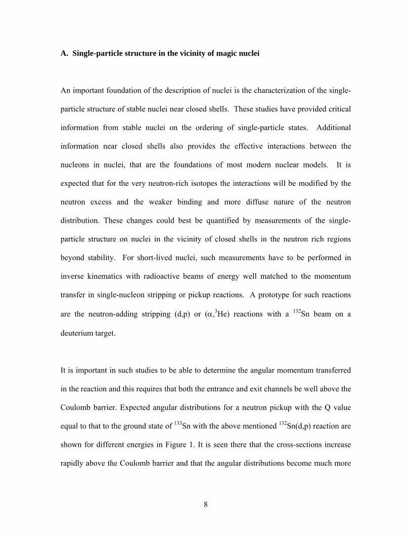
It is important in such studies to be able to determine the angular momentum transferred
in the reaction and this requires that both the entrance and exit channels be well above the
Coulomb barrier. Expected angular distributions for a neutron pickup with the Q value
equal to that to the ground state of 133Sn with the above mentioned 132Sn(d,p) reaction are
shown for different energies in Figure 1. It is seen there that the cross-sections increase
rapidly above the Coulomb barrier and that the angular distributions become much more
8

distinctive. For the (d,p) reaction on Sn, the optimum energy is around 7.5 MeV/u.
Pioneering work is being carried out at Holifield on this reaction at the sub-Coulomb
energies 4.7 MeV/u that are an extremely useful first step. However to be able to assign
high-l states (such as the i13/2) higher energies are essential, and the sensitivity of the
cross sections at sub-Coulomb energies to the exact radius also favors higher energies for
more quantitative measurements of the spectroscopic factors, to establish whether the
states are indeed single-particle in character. The high-l states will still be relatively weak
in the (d,p) reaction, however in (α,3He) above ~ 10 MeV/u they stand out with unique
strength (see Figure 2). Yields will be on the order of tens of counts/day per single-
particle state for beams on target of 104/s for the (d,p) reaction, and a few a day for high-
l single-particle states in (α,3He).
Figure 1. Calculated differential cross-sections for different angular momentum transfer in the 132Sn(d,p) reaction to a state at a Q value equivalent to that of the ground state of 133Sn at three different beam energies.
132Sn(d,p) 3.5 MeV/u
0
10
20
0 90 180angle (degree)
cros
s-se
ctio
n (m
b/sr
)
L=0
L=1
L=2
L=3
L=4
L=5
L=6
132Sn(d,p) 4.7 MeV/u
0
10
20
30
0 90 180
angle (degree)
cros
s-se
ctio
n (m
b/sr
) L=0
L=1
L=2
L=3
L=4
L=5
L=6
132Sn(d,p) 7.5 MeV/u
0
10
20
30
40
50
0 90 180angle (degree)
cros
s-se
ctio
n (m
b/sr
)
L=0
L=1
L=2
L=3
L=4
L=5
L=6
9

While 132Sn is mentioned as an example, the measurements over the whole region of
neutron rich nuclei would be of interest, including close to the N=50 line above 78Ni.
Obtaining information on the angular distributions requires radioactive beams of about
104 particles per second with now standard segmented silicon detector arrays. A facility
that can not only provide the required energy, but also has a fast universal extraction
technique that can allow a whole region of neutron-rich beams to be studied, is needed
for such studies so that, for example, the yield of neighboring isotopes like 133Sn (t1/2 =
1.45s) is not orders of magnitude below that of the central 132Sn (t1/2 = 39.7s) isotope.
Novel instruments such as the solenoid spectrometer [1] being proposed at Argonne
could further reduce the required beam intensity, maybe by a factor of 2 or 3.
It is important to emphasize, that such studies will be a major area of investigation with
RIA whose capabilities will greatly exceed those of the proposed upgrade. However the
ATLAS Cf upgrade will open up considerable ground, complement the pioneering work
at Holifield, and begin an exploration into the foothills of the regime that will be
addressed by RIA, helping to refine experimental techniques in the process.
132Sn(α,3He) 11 MeV/u
0.001
0.01
0.1
1
10
0 10 20 30 40 50
angle (degree)
cros
s-se
ctio
n (m
b/sr
)
L=1
L=3
L=5
L=6
Figure 2. Calculated differential cross-sections for different angular momen-tum transfer in the 132Sn(α,3He) reaction to a state at a Q value equivalent to that of the ground state of 133Sn. This reaction is matched most effectively to higher angular momen-tum transfer.
10

The (d,p) reaction can also play an important role in obtaining information for the (n,γ)
rates on neutron-rich nuclei which must be determined to verify the validity of the steady
state approximations used in many r-process models. Characterizing the states near the
neutron threshold, and the bound states to which capture would occur can be carried out
for a number of cases.
B. Pairing interaction in neutron rich nuclei
The pairing interaction plays an important role in nuclear structure. Measurements using
nucleon-pair adding or removing reactions such as (p,t), (t,p) and (3He,n) on stable nuclei
were important in determining its nature and strength. It is, however, possible that the
pairing interaction determined in stable nuclei will be modified in neutron-rich systems
by the lower nuclear density. The two-neutron pairing interaction in weakly bound
neutron-rich nuclei could be determined by measuring the energies and strengths of
excited 0+ states (paired neutron particles or holes) using (p,t) and (t,p) reactions on
neutron rich nuclei. In simple BCS theory all the strength is in the ground state and
other excited 0+ states should be weak; in practice they are on the order of 1 % of the
ground state. Where pairing breaks down, excited 0+ states are populated with much
larger (10-30% of the ground state) strengths.
11

Q-value for AZr(t,p) and AZr(p,t) reactions
-4
-2
0
2
4
98 100 102 104 106 108
Mass number (A)
Q-v
alue
(MeV
)
Zr(t,p)Zr(p,t)
Figure 3. Q value for (t,p) and (p,t) reactions on neutron rich zirconium isotopes.
In the case of short-lived nuclei, these reactions are better performed in inverse
kinematics at energies determined by the Coulomb barriers and the Q values. A typical
example would be such reactions on neutron-rich zirconium isotopes for which the Q
values are shown in Figure 3. It is observed that in this region of the nuclear chart the Q
values for (p,t) reactions, reactions that bring us back towards stability, become more
favorable as one moves away from stability. As a result, the (p,t) reactions on the most
neutron rich isotopes and the (t,p) reactions on all nuclei can be performed with the
energies of up to about 9 MeV/u that are available without stripping for A~100 nuclei
with the current ATLAS accelerator. The (p,t) reactions on the closer to stability
neutron-rich isotopes are best performed with the higher energies (see Table 1) that will
be available after the current AIP funded ATLAS accelerator energy upgrade is
completed. Using the proposed solenoid spectrometer the (p,t) reaction will yield on the
order of 12 counts/day for 104 particle a second incident on a target – one would probably
want at least 100 counts to set some limits on the fragmentation of pairing strength.
These studies in more neutron-rich beams will be an important area of investigation with
RIA and a start can be made with the proposed Cf upgrade to identify this behavior.
12

A No Strip Strip No Strip Strip1 24.1 24.1 38.5 38.52 15.7 15.7 23.2 23.2
16 13.0 15.7 18.5 21.540 12.4 13.4 17.5 19.958 9.9 11.8 13.5 17.978 9.5 11.2 12.8 16.7
132 8.0 9.3 10.4 13.4197 6.6 7.9 8.4 10.9238 6.4 7.4 7.9 10.0
Current ATLAS UPGRADE I
Table 1. Energies in MeV/u available at ATLAS without and with stripping for ions of various mass with the existing configuration and after the ongoing AIP funded accelerator upgrade.
C. Gamma ray studies of neutron rich nuclei
Accelerated fission fragment beams near the Coulomb barrier offer interesting
opportunities for gamma-ray studies with Gammasphere. The mass and charge
distribution of the fission fragments from californium cover highly deformed nuclei and
the shape transitions in the A~100 and A~130 regions that provide an excellent
complement to studies of spherical nuclei near 132Sn performed at Oak Ridge following
proton-induced fission of uranium.
The phase transition between spherical and deformed nuclear ground states has received a
lot of attention recently as the nuclei at the transition points have been shown to have
unique signatures. The californium fragments cover several important shape transitions.
Some are first order like the abrupt shape change in the zirconium isotopes, while others
are much more gradual second order changes, for instance in the barium and cerium
13

isotopes. The regions where the fragments are copiously produced should allow
“vertical” isotonic phase changes to be delineated near N=64 and N=90 for the first time.
The experimental test of these transitions lies in following the collectivity of yrast and
non-yrast structures and observing how they cross and mix. Coulomb excitation of the
accelerated fission fragments at energies near the barrier is a precise and discriminating
tool for this research. The high degree of symmetry of Gammasphere and its good
efficiency are perfectly matched to these experiments. The use of very inverse
kinematics, using a beryllium or carbon target followed by residue identification, has
been shown at Oak Ridge [2] to allow spectroscopy of very weakly produced exotic
isotopes in a “cocktail” of isobarically mixed beams.
The nature of single-particle states in very neutron-rich nuclei is of major interest, as it
allows us to seek evidence for isospin dependent modification of residual interactions.
One of the more precise tests of the composition of nuclear wave functions is through
measuring nuclear magnetic moments. A precise technique that is suitable for fission
fragment beams uses the transient fields encountered by fast moving highly stripped ions.
Coulomb excitation of the fragment beams allows interesting states to be populated and
aligned in a known fashion, then the subsequent precession caused by the interaction of
the nuclear moment and the field can be followed by measuring the decays. Again, the
high degree of geometric symmetry makes Gammasphere an ideal tool for this research.
In the light fragment mass peak, around 104Zr, lie nuclei with some of the largest ground
state deformations known, β2~0.4. Accelerated beams of short-lived isotopes of
14

zirconium (and most neighboring elements in fact) are not available at existing facilities.
Prompt spectroscopy of gamma rays emitted following fission have provided some
information on low-lying states in these nuclei, but Coulomb excitation of mass separated
and accelerated beams would allow the microscopic structure of these collective modes to
be established and their stiffness against beta and gamma vibration, and rotation, to be
investigated. These nuclei have been predicted to have even more highly deformed
structures at high spin. Whether these states can be populated by inelastic excitation
depends on the degree to which the configurations mix. If the shape evolution is
adiabatic then population may be possible, but if the configurations are well separated, as
is found in most superdeformed nuclei, they will be more difficult to probe.
104Zr provides a good case for a more quantitative insight of gamma ray experiments
possible with the proposed upgrade. Its ground state deformation and low-lying levels are
already known from recent prompt gamma spectroscopy of emissions from a fission
source. Extrapolating these properties, and assuming rigid rotor behavior to the very
highest spins, allows the calculation of expected yields in a conventional thin target
Coulomb excitation study, for example using CHICO (the Rochester chamber for
studying inelastic scattering) and Gammasphere. For example, with a beam of 2 x 10⁴
particles per second on a lead target at a safe energy for electromagnetic excitation, the
first excited state is populated with a cross-section approaching 5 barns and 100 hours of
data collection would yield ~10,000 photopeak decays, about 2/3 of which would have at
least 1 coincident gamma ray full energy photopeak from multiple excitation. Even a few
decays from the (unknown) J=20 state should be detectable. For “pure” beams, stopping
15

in a thick target would enhance yields by a factor 2-5, and allow crosschecks of
collectivity through fitting DSA line shapes. Increasing the beam energy into the
“unsafe” region where both electromagnetic and nuclear processes occur would also
enhance the yields at the cost of losing the predictability and cleanliness of Coulomb
excitation. In addition, the higher energies would allow few-nucleon transfer studies
populating neighboring nuclides. In most cases the interesting spectroscopy would
involve identifying new states in coincidence with the known low-lying levels so that a
considerable level of contamination from a “cocktail” beam could be tolerated.
Another collective mode in this region is that of octupole collectivity. Neutron-rich
barium and cerium nuclei are known to exhibit features consistent with significant
octupole collectivity, probably vibrational, but discriminating tests can only come from
measuring dipole and octupole matrix elements. These measurements have not been
possible up to now, but are straightforward in Coulomb excitation studies with the
proposed beams.
The issue of using fission fragment beams to induce fusion reactions is worth
consideration as a tool for studying even more neutron-rich nuclei. In general, reactions
on heavy targets do not look promising, as the fused systems tend to lie close to the
valley of stability, due to its curvature, and neutron evaporation is calculated to be very
probable. However, this method may be important in some cases to populate high spin
isomers that cannot be reached by other means. A further possibility is the investigation
16

of fusion with neutron rich targets, like 14C, and observing charged particle evaporation
from the compound nucleus to tag the production of nuclei far from stability.
D. Nuclear properties and decay studies along the r-process path
The r-process is responsible for the formation of roughly half of the nuclei above iron.
The high neutron flux and high temperatures that occur in explosive events such as type
II supernovae explosions or possibly neutron star mergers convert seed material into
heavier elements via a series of neutron captures and beta decays. Neutrons are captured
on the seed nuclei via (n,γ) reactions leading to more and more neutron-rich nuclei.
Simultaneously, the high temperature generates a high flux of thermal gamma rays that
can destroy these neutron-rich nuclei via (γ,n) reactions. The competition between these
reactions yields an equilibrium distribution of neutron-rich isotopes of a given element
determined by the temperature and the neutron separation energies. Beta decay provides
a path to the next heavier element where the (n,γ) and (γ,n) reactions again yield an
equilibrium distribution for neutron-rich isotopes of this next element. The neutron flux
is large enough for the reactions to be much faster than the beta decay rates and so the
process continues and leads to heavier and heavier elements via a path situated far on the
neutron-rich side of the nuclide chart. It is estimated that the event lasts only one to tens
of seconds after which the created neutron-rich isotopes decay back to stability to yield
the observed isotopic distribution.
17

The path followed by the r-process is determined by the ground state properties of the
neutron-rich isotopes involved. The location of the path, for a given temperature, is
determined by the neutron separation energies and hence the masses (mass differences) of
these isotopes. The timescale to create the heavier isotopes is determined by the beta
decay lifetime of the neutron-rich isotopes along the path. And, finally, the remaining
isotope distribution that is the key signature of the r-process is affected not only by the
beta decay lifetimes along the path, but also by the beta-delayed neutron emission
probability. The path followed by the r-process is, however, so far from the valley of
beta stability that most of the isotopes of interest have not been accessible in the
laboratory. Figure 4 shows the limit of known masses together with isotope production
from a californium source and an outline of the r-process path. Only a small fraction of
the isotopes along the path have had even their most basic property, i.e. their mass,
measured. The situation is only slightly better for the lifetime and decay properties.
Modeling of the r-process therefore depends on extrapolation of the properties of known
isotopes to region where we have reasons to believe the physics is modified. This is
highly unsatisfactory and a more detailed understanding of the r-process requires
obtaining an improved knowledge of the ground state properties of very neutron-rich
isotopes.
The mass of a short-lived isotope can be measured to an accuracy of 10 keV/c2 or better
with the Penning-trap based CPT mass spectrometer and an isotope production of a few
ions per minute. All isotopes identified in Figure 4 could have their masses measured to
this accuracy, including roughly 180 very neutron-rich isotopes in the close vicinity of
18
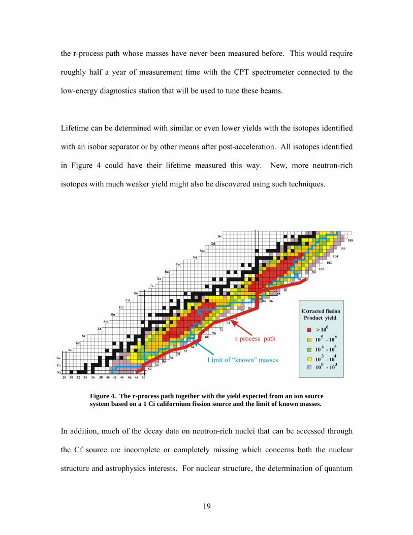
the r-process path whose masses have never been measured before. This would require
roughly half a year of measurement time with the CPT spectrometer connected to the
low-energy diagnostics station that will be used to tune these beams.
Lifetime can be determined with similar or even lower yields with the isotopes identified
with an isobar separator or by other means after post-acceleration. All isotopes identified
in Figure 4 could have their lifetime measured this way. New, more neutron-rich
isotopes with much weaker yield might also be discovered using such techniques.
Figure 4. The r-process path together with the yield expected from an ion source system based on a 1 Ci californium fission source and the limit of known masses.
In addition, much of the decay data on neutron-rich nuclei that can be accessed through
the Cf source are incomplete or completely missing which concerns both the nuclear
structure and astrophysics interests. For nuclear structure, the determination of quantum
19

numbers, log ft, etc … and the elucidation of single -particle levels in odd-mass isotopes
are important for the understanding of neutron-rich nuclei. For nuclear astrophysics, well
understood level schemes are of importance, especially in predicting (n,γ) and (γ,n) cross
sections along the r-process path. In addition, many of the odd-odd isotopes have two (or
more) beta decaying states that may have significantly different lifetimes. There is a
coupling of these states in hot stellar environments that in turn affect the decay rates
along the r-process path. The structure coming from β-decay studies would be of
importance to elucidate such effects. Finally, the beta-delayed neutron emission
probability is required to calculate the final isotope distribution following the r-process
and such measurements could be done here on a number of nuclei on the r-process path.
In this case, as is the case for the lifetime and mass measurements mentioned above, the
nuclei around the N=50 and N=82 closed shells are of particular importance for the
r-process calculations and these measurements could be done in parallel to the mass
measurements.
E. Laser spectroscopy of neutron-rich nuclei
Laser spectroscopy has been a key tool to investigate properties of the nuclear ground
state and isomers of short-lived isotopes. Isotope shifts in atomic transitions reflect the
change in charge radii between isotopes and are an excellent probe for nuclear shape
transitions and halo phenomena. The hyperfine structure of atomic transitions reveals the
nuclear spin, and the magnetic dipole and the spectroscopic quadrupole moment of the
nucleus can be inferred from the energy splitting between hyperfine levels. These
20
experimental data are highly accurate, can be extracted independently of nuclear models
and are very sensitive to both single-particle and collective properties. They therefore
provide excellent tests for nuclear models.
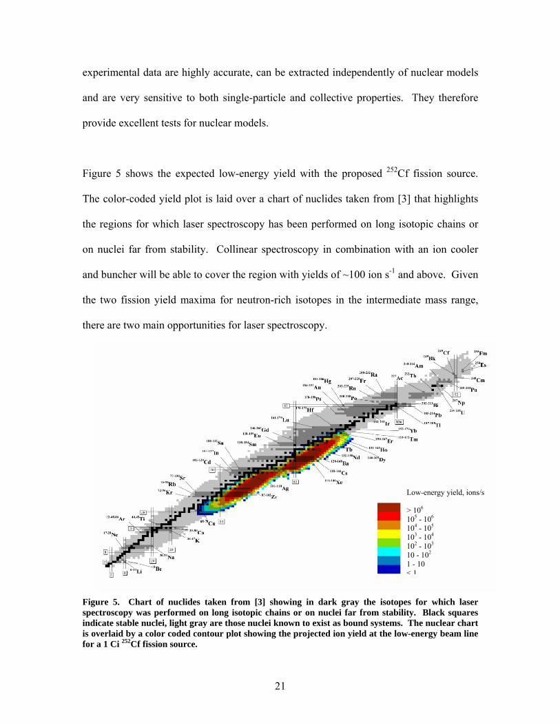
Figure 5 shows the expected low-energy yield with the proposed 252Cf fission source.
The color-coded yield plot is laid over a chart of nuclides taken from [3] that highlights
the regions for which laser spectroscopy has been performed on long isotopic chains or
on nuclei far from stability. Collinear spectroscopy in combination with an ion cooler
and buncher will be able to cover the region with yields of ~100 ion s-1 and above. Given
the two fission yield maxima for neutron-rich isotopes in the intermediate mass range,
there are two main opportunities for laser spectroscopy.
Low-energy yield, ions/s
> 106
105 - 106
104 - 105
103 - 104
102 - 103
10 - 102
1 - 10< 1
Figure 5. Chart of nuclides taken from [3] showing in dark gray the isotopes for which laser spectroscopy was performed on long isotopic chains or on nuclei far from stability. Black squares indicate stable nuclei, light gray are those nuclei known to exist as bound systems. The nuclear chart is overlaid by a color coded contour plot showing the projected ion yield at the low-energy beam line for a 1 Ci 252Cf fission source.
21

The first is to continue the measurements of long isotope chains further to the neutron-
rich side and to observe how charge radii and moments change by adding more and more
neutrons. These investigations also have the potential of discovering previously
unobserved isotopes and isomers. Isotope chains of interest are those of silver, cadmium,
indium and tin. Of particular interest is the possibility to extend the existing data on
indium isotopes to reach the N=82 shell closure at 131In and to measure the nuclear
properties beyond the double magic 132Sn [4]. Additional areas of interest for continuing
existing measurements and start the measurement of new isotope chains are the refractory
elements from ytterbium to palladium [5] and very neutron-rich isotopes of the rare earth
elements from lanthanum to holmium.
The second opportunity is to investigate the isotopes along the neutron-rich side of the
largely unexplored N=50 shell closure from zinc to selenium and possibly bromine and to
follow the N=82 shell closure further to antimony and tellurium.
F. Stockpile stewardship
Determining quantities of interest to the stockpile stewardship program will come
naturally with the californium upgrade project. Determining the properties of neutron-
rich fission fragments such as masses and, possibly, more accurate ground state lifetimes
are among these. In addition, investigations of the neutron-adding (d,p) reactions on such
nuclei hold important clues that can allow for more reliable estimates of neutron cross
22

sections on these isotopes. Other reactions may allow a check of the applicability of
statistical properties to such nuclei that provide important checks. The proposed
technique is particularly suitable for the explorations of the properties of neutron-rich
isotopes of zirconium and yttrium that are of particular interest.
IV. Conceptual Overview
The neutron-rich region of the chart of nuclides is the next frontier in low energy nuclear
physics and we have highlighted above some of the tools necessary to chart and
understand this region. The task requires performing experiment with beams of short-
lived neutron-rich isotopes in specific energy regimes. Interesting capabilities now exist
for radioactive beams in this region at the Holifield facility and will soon exist at the
ISAC and REX-ISOLDE facilities. Limitations in the species that can be extracted and
the energy to which they can be accelerated however hamper the ability of these facilities
to address a number of key physics questions. The ATLAS facility at Argonne has a
unique potential in that it has the required capabilities and expertise to become, with a
modest upgrade, a very cost effective facility to perform this research. In fact, with this
upgrade, ATLAS will have radioactive beam capabilities that will be unmatched on a
national and international scale. It will be an important tool to pave the way and prepare
the field for the RIA era. It will also demonstrate in battle conditions many of the
technologies that are critical to RIA.
23

The necessary steps to accomplish the task are (1) the production of the short-lived
isotopes, (2) the rapid extraction and preparation of the selected isotopes, (3) their post-
acceleration to the optimum energy for the particular experiment, and finally (4) the
availability of the required instrumentation to carry out the experiments. New techniques
developed at ATLAS for the CPT trapping program and for the RIA facility enable the
stopping of fast recoil ions into a gas catcher and their rapid extraction as a low-energy
beam of very good quality. This technique is applicable to essentially all species and is
very efficient. We propose to use such a gas catcher to stop recoils from a 1Ci 252Cf
fission source and to extract them as a low-energy beam. This provides access to all
species produced in the fission of californium. In particular, this puts within reach
species which are difficult to extract by standard ISOL techniques and are not produced
with low-energy fission of uranium. This approach therefore provides unique beams that
will not be available elsewhere until facilities like RIA come along.
The californium source and gas catcher will be located, together with an RFQ gas cooler
and an isotope separator, on a new high-voltage platform. This new platform will be
located at ATLAS besides the ECR-1 high-voltage platform and have an independent
high voltage control with output that can be compared and adjusted versus the ECR-1
high voltage. The extracted isotopes are transported and cooled in two sections of RFQ
gas coolers yielding beams with very low transverse emittance and energy spread. The
beams are then accelerated to 50 keV and sent to a high-resolution mass separator where
a specific isotope is selected. The very good beam properties extracted from the gas
cooler allows one to obtain a mass resolution of 20000 with a one-stage separator that is a
24

scaled down version of the isobar separator that has been designed for low-energy beam
purification at RIA. Two beamlines will be attached to the isobar separator; a low-energy
beamline for tuning/diagnostics and low-energy experiments, and a beamline leading to
the existing ECR-1 high voltage platform. Most unwanted activity will be stopped in the
mass separator and remain on the first high-voltage platform. This platform is expected
to be the only location where sizable accumulation of radioactive isotopes will occur.
Post-acceleration of the low energy beams extracted from the first platform must be done
efficiently. In the context of RIA, a large effort has been devoted at Argonne to develop
high efficiency approaches to perform the post-acceleration of low charge-state ions. It
was determined that the most efficient approaches require an ATLAS-like high-
acceptance superconducting linac. In fact, ATLAS is proposed as a component of the
post accelerator if the RIA facility is sited at Argonne. The main approach for post-
acceleration at RIA will use low-velocity RFQs and non-equilibrium charge state
stripping to then inject into an extended low-energy section similar to the existing
ATLAS PII linac before completing the acceleration in the booster and ATLAS sections.
This approach is the most efficient at all energies and, in particular, shows the highest
gain over other approaches for astrophysics type energies below 1-1.5 MeV/u.
A second [6,7,8] approach, inferior at very low energy, but almost as efficient at
Coulomb barrier energy, will also be used at RIA. A charge-state breeder will be used to
increase the charge state of the singly charged radioactive ions so that they can be
accelerated directly in ATLAS. This will provide an independent acceleration route to
25

the experimental area for physics at the Coulomb barrier that can be used during long
experiments in the astrophysics area. It will greatly enhance the multi-user capabilities
of RIA. We propose to use this same approach in this upgrade. For the mass range
covered by fission fragments and at the Coulomb barrier energies which are of interest
for the proposed physics program it yields almost the same efficiency as the full RIA
post-accelerator but at a much lower cost.
The ECR-1 ion source will be modified to be used as a charge-state breeder (it will
remain usable as an ECR source for normal ATLAS operations). The mass selected
singly (or doubly) charged ions will be injected into the ECR-1, their charge state
increased by the plasma, and they will then be extracted and sent to ATLAS in a fashion
identical to normal stable beams.
Only minor modifications to ATLAS will be implemented for this upgrade. The energy
range that will be accessible after the current AIP funded ATLAS energy upgrade is
completed will be sufficient to address the physics questions put forth above.
Transmission of the ATLAS accelerator is very high, limited in theory only by the
bunching efficiency that should be up to 85% with the multi-harmonic buncher currently
in use. In practice, there are a few “apertures” in the beamline that are there for historical
reasons and that limit the tuning range available making the highest transmission
efficiency difficult to obtain. They will be removed. Diagnostics will also be improved in
the injection into ATLAS to obtain better tunes for standard beams and extend their
26

usefulness to lower intensity beams. Both of these actions will be taken to provide the
highest post-acceleration efficiency possible.
Finally, ATLAS already possesses first class instrumentation for most of the studies
being proposed with Gammasphere, the FMA, the CPT mass spectrometer, and the
Ludwig detector array and Enge spectrographs. In addition, a proposal has been
submitted for a solenoid spectrometer for reaction studies with radioactive beams that
would further enhance the existing capabilities.
V. Technical Description
The various components of the upgrade presented above will be described individually in
more details below.
A. Source of radioactive isotopes
Neutron-rich isotopes are generally obtained from proton, neutron or photon induced
fission of uranium. Low-energy proton-induced fission of uranium is used effectively as
a source of neutron-rich isotopes at the sole US facility with accelerated fission product
beams, HRIBF at Oak Ridge. This approach has well defined production peaks and little
production outside these regions. In addition, further limitations in the species extracted
are present with the standard ISOL methods and the post-acceleration schemes used. The
physics program proposed above requires access to isotopes not available with existing
27
facilities in the US or abroad. This requires both a different production technique and a
more universal extraction approach. Different approaches to producing the neutron-rich
isotopes have been investigated and it was concluded that fission sources are a promising
alternative to beam induced fission.
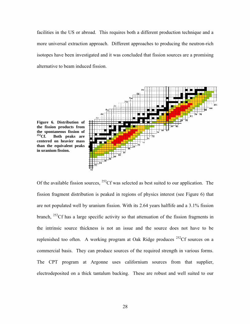
Figure 6. Distribution of the fission products from the spontaneous fission of 252Cf. Both peaks are centered on heavier mass than the equivalent peaks in uranium fission.
Of the available fission sources, 252Cf was selected as best suited to our application. The
fission fragment distribution is peaked in regions of physics interest (see Figure 6) that
are not populated well by uranium fission. With its 2.64 years halflife and a 3.1% fission
branch, 252Cf has a large specific activity so that attenuation of the fission fragments in
the intrinsic source thickness is not an issue and the source does not have to be
replenished too often. A working program at Oak Ridge produces 252Cf sources on a
commercial basis. They can produce sources of the required strength in various forms.
The CPT program at Argonne uses californium sources from that supplier,
electrodeposited on a thick tantalum backing. These are robust and well suited to our
28
application since the fission fragments have a 2π solid angle to escape the source and
backing and be subsequently captured in the gas catcher.
The source will have a total activity of 1 Ci and be electrodeposited on a flat 0.1” thick
tantalum backing located on a source holder (similar to that used in [13]). The
deposition will have a diameter of 5 cm, yielding a density of 51 mCi per cm2.
Californium sources with 5 mCi per cm2 density (0.6 mCi over a 0.4 cm diameter spot)
are currently in use at the CPT spectrometer. No sign of flaking or any other form of
activity loss has been observed under these low-density conditions. Stronger
electrodeposited open 252Cf sources were also prepared at Oak Ridge for the gas jet
system [12] at Idaho National Engineering Laboratory with total activity of 0.25 Ci over
a few cm2. That source density exceeds our requirements and it was successfully operated
there. The 1 Ci source will be inside the gas catcher and be covered by a 2 mg/cm2 gold
foil located one mm above the source for protection and confinement. It will enclose the
source, except for a pumping hole to equilibrate pressure inside the trapped volume with
the gas catcher pressure. The foil will be mounted on the source by remote handling in
the chemistry hot cell after reception of the source at Argonne, using techniques similar
to that used in [13]. An additional degrader will be supported above the gold foil to tailor
the energy loss of the recoils to the geometry of the gas catcher as explained below.
29

B. Gas catcher and degrader
The critical step in the production of radioactive beams is the efficient transformation of
the activity into a low energy beam that can be further accelerated. As mentioned above,
this step must be as universal as possible to access the difficult elements that are of
physics interest. Efficiency is also critical since it determines not only the final yield, but
also the size of the radioactive inventory that has to be handled and shielded. The gas
catcher technique, an approach combining both universality and high efficiency, has been
developed at Argonne first for injection into the CPT mass spectrometer and then for the
RIA facility [9]. It is ideally suited to this task.
The gas catcher thermalizes incoming radioactive ions as singly or doubly charged ions
that are then extracted as a cold beam by a combination of DC fields, RF fields, and gas
flow. The californium source will be located at the entrance of the gas catcher; the fission
fragments will be slowed down in a degrader foil and then stopped in high purity helium
before being extracted. Gas catchers have been in operation at ATLAS for about 5 years
and the basic operational principles are now well understood. The initial step in
designing a gas catcher for this specific application is to determine the volume of high
purity helium gas that is needed to thermalize fission fragments of a given range. Studies
were performed with the Monte Carlo version of the code SRIM to determine the
effective range distribution obtained with various degrader configurations in front of a
californium source.
30

From such studies, it was determined that a gas catcher with a gas pressure of 150-200
mbar, an inside diameter of 25-30 cm and a length of 60 cm would be best suited to
stopping both light and heavy fission fragments. For such a volume and for a specific
degrader configuration, most of the fission fragments emitted into the open 2π solid angle
will be stopped in the gas. The radioactive ions are thermalized as singly or doubly
charged ions in the high purity helium gas and must then be extracted from the gas
volume before they decay or are lost to charge exchange processes with impurities in the
gas or to collisions with the chamber walls. To avoid any appreciable losses, the
extraction must be performed on a time scale of 20 ms or less, much faster than can be
achieved by gas flow alone. This is obtained with the gas catcher concept developed and
successfully used at Argonne. It utilizes a combination of DC and RF fields
superimposed on the gas flow to effectively and quickly extract the isotopes stopped in
high-purity helium gas. The combination of the three forces provides: fast transport
through the main part of the device (DC field), focusing toward the extraction nozzle (RF
field), and rapid extraction through the nozzle (gas flow). This scheme allows the use of
a much larger stopping gas volume than would gas flow alone, as well as the handling of
much higher intensities than a DC field-based system.
The ionization in the gas catcher needs to be considered. The gas catcher scheme was
first demonstrated at ATLAS and is now a central component of the very successful
physics program at the CPT mass spectrometer. This scheme overcomes the limitations
of some of the earlier gas stoppers. At present, it has been used with ionization of over
31

1011 helium-ion-electron pairs per second in a cell with a volume of 0.8 l. With a 1Ci
source, including the contributions from both the alpha particles and fission recoils, one
expects roughly 4.5 X 10¹⁴ helium-ion-electron pair per second in a volume of ~45 l.
This corresponds to about a factor of 60 beyond the present experience. However, this is
still roughly 10 times lower than what is required for the RIA application. A test of the
RIA gas catcher at high-intensity is in preparation at ATLAS as part of the RIA R&D and
calculations indicate that it will be sufficient to handle the space-charge repulsion created
by such a charge cloud. This intensity is too low to create any “plasma” effects. The
main issue here becomes one of helium gas purity since the helium ions can be handled
fairly easily as long as they do not transfer charge to contaminants; measures to maintain
the gas purity required are discussed below. It should also be noted that helium ions that
are created do not leave the gas catcher; only the heavy ions (and charged heavy
impurities) are extracted so that the current in the subsequent devices is much lower than
in the gas catcher. The requirements for the present application can be fulfilled by a
shortened version of the RIA gas catcher prototype.
Figure 7. View of the extraction region of the RIA gas cell prototype. This section consists of 279 plates operating with RF voltage applied between the odd and even plates to focus the ions to the extraction aperture.
32

The full-scale RIA gas catcher prototype is a complex yet reliable device with more than
7400 components. Figure 7 shows the extraction section of the RF cone, the most
complex section of the device. Strong RF fields on the 279 plates forming the cone
create an RF wall that does not allow the radioactive ions to come closer than a few mm
to the cone while they are dragged forward by the DC field until the gas flow takes them
out via the final nozzle at the cone apex. The extraction cone is attached to the gas
catcher main body composed of modular cylindrical sections. These sections provide
most of the stopping volume and a strong DC field that moves the ions forward towards
the RF cone and extraction nozzle. The RIA prototype gas catcher (see Figure 8) used 7
cylindrical sections connected to the RF cone chamber, the gas catcher for the
californium upgrade will use a similar RF cone connected to 3 cylindrical sections, the
first section hosting the fission source and degrader.
Figure 8. Assembled RIA gas catcher proto-type with tuned circuit to provide RF and DC potentials to the body and cone electrodes. The extraction nozzle and chamber hosting the extraction cone can be seen on the left side of the picture.
33

The gas purity requirements in the gas catcher are extremely high. It operates with a
continuous helium gas flow of 10 SLM. This is equivalent to a continuous pumping
speed of roughly 1 liter per second. Maintaining the required ppb level purity in the
helium therefore sets an upper limit of 10-7 Torr-liter/second for the total outgassing rate
inside the gas catcher. This can only be achieved with UHV materials and techniques
applied to the gas catcher fabrication. This was obtained in the RIA prototype gas
catcher by using only metal and ceramics in the construction and using indium seals to
join the different sections. A similar construction approach will be used here, except for
minor modifications to make the system more modular and capable of sustaining baking
at higher temperatures. This will be done by replacing the large insulator rings used in
the RIA prototype by an insulating enamel coating and the indium seals by Helicoflex all-
metal seals. These all-metal seals on enamel surfaces are radiation resistant, easy to
replace and reliable. The gas flow of 10 SLM is small enough to be accommodated by a
pumping system that can fit on a high voltage platform. The helium gas is coming from
cylinders that are stored off the high voltage platform. The gas is brought up to the high
voltage platform at high pressure in an electrically insulated line. It is then purified in a
cold trap and transported in an all-metal distribution system first to a Monotorr solid state
purifier (SAES Getters) for further purification before finally being fed to the gas catcher.
The required radioactive ion extraction time is attained with a total DC voltage of roughly
1000 volts along the gas catcher. A total RF power of about 1 kW is needed to provide
the 1 MHz RF field required on the RF cone with its roughly 100 nF capacitance. This is
obtained with an air-core inductance forming a tuned circuit with the cone plates and the
34

voltage distribution system, with the circuit fed by a 150 watts RF amplifier. The gas
catcher system is installed in a high-voltage cage enclosed in radiation shielding.
C. Transport cask
The 1 Ci 252Cf source used to produce the radioactive ions is a major source of
radioactivity. The main activity is high-energy alpha particles which can be shielded
easily. The fission branch itself is, however, accompanied by the emission of neutrons
which are a much more serious concern. In addition, the fission fragments emit betas and
gammas which also require shielding. The unshielded source generates fields of about 44
rems/hr at 30 cm and can therefore be handled only remotely in hot cells and transported
under heavy shielding. The source, deposited on a 5 cm diameter tantalum disk mounted
on a source holder, will be brought to Argonne’s existing hot cell facility located in the
Chemistry Division building. Some refurbishing of the hot cell manipulators is required
for this task and the resulting cost is included in this proposal. The source size is small
enough for a standard commercially available and certified lead pig to be used for storage
during transport from Oak Ridge to Argonne. There it will be remotely mounted on a
support plug that fits in the back of the gas catcher (this is similar to the technique [13]
used for the gas jet experiments at INEL with similar strength sources) and the thin gold
foil mounted on it. The plug is installed in a large movable cask with about 60 cm
borated polyethylene and lead shielding surrounding the source and plug (see Figure 9).
Transport between the hot cells and the gas catcher is performed in the shielded cask by
the Special Materials Group. The radiation limits they can handle are 200 mrem/hr on
contact and 10 mrem/hr at 2 meters so that in principle a much smaller cask for the
35

transportation and more local shielding at the gas catcher could be used. At this point we
are opting for the more conservative solution. The cask is moved to the high voltage
platform at ATLAS and installed on rails to guide it to the gas catcher and its permanent
shielding. The procedure to install the source inside the gas catcher is shown in Figure 9.
The cask is pushed up to the permanent gas catcher shielding, the cask is opened and the
source and plug moved forward and attached to the gas catcher, the pusher is pulled back
into the cask and the cask closed. The cask remains in location and becomes part of the
shielding for the gas catcher. The procedure is reversed to remove the source and plug
from the gas catcher.
Figure 9. Schematic view of the cask used to transport the fission source from the hot cells to the gas catcher. The top 6 frames depict the steps necessary to insert the source.
D. RFQ gas cooler
The radioactive ions extracted from the gas catcher are extracted in the presence of a
large gas flow. The gas pressure at the nozzle is high enough to disturb the acceleration
36
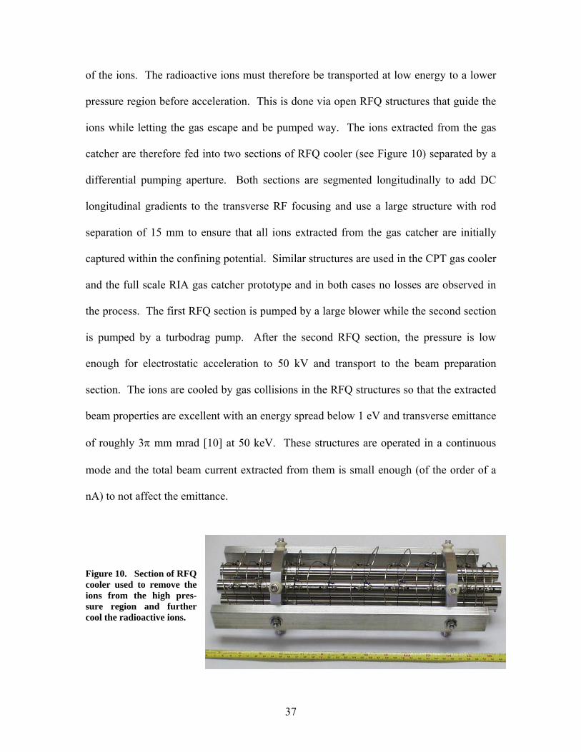
of the ions. The radioactive ions must therefore be transported at low energy to a lower
pressure region before acceleration. This is done via open RFQ structures that guide the
ions while letting the gas escape and be pumped way. The ions extracted from the gas
catcher are therefore fed into two sections of RFQ cooler (see Figure 10) separated by a
differential pumping aperture. Both sections are segmented longitudinally to add DC
longitudinal gradients to the transverse RF focusing and use a large structure with rod
separation of 15 mm to ensure that all ions extracted from the gas catcher are initially
captured within the confining potential. Similar structures are used in the CPT gas cooler
and the full scale RIA gas catcher prototype and in both cases no losses are observed in
the process. The first RFQ section is pumped by a large blower while the second section
is pumped by a turbodrag pump. After the second RFQ section, the pressure is low
enough for electrostatic acceleration to 50 kV and transport to the beam preparation
section. The ions are cooled by gas collisions in the RFQ structures so that the extracted
beam properties are excellent with an energy spread below 1 eV and transverse emittance
of roughly 3π mm mrad [10] at 50 keV. These structures are operated in a continuous
mode and the total beam current extracted from them is small enough (of the order of a
nA) to not affect the emittance.
Figure 10. Section of RFQ cooler used to remove the ions from the high pres-sure region and further cool the radioactive ions.
37

E. Isobar separator
ne of the great advantages of the approach being proposed here is the universality of the
igure 11. Plot of the masses and cal-culated low-energy yields for A=108 (top)
O
extraction technique that makes it possible to obtain beams of all species produced in the
fission process. That advantage is maintained in the post-acceleration where the
superconducting linac, with its large acceptance, accelerates efficiently all species. Some
mass selection (actually magnetic rigidity selection) is present in the post-acceleration but
for practical purposes it is limited to about 1 in 400 resolution, enough to remove
neighboring masses but not isobars.
Yield and mass of A=132 isotopes
1.0E+04
1.0E+05
1.0E+06
1.0E+07
34 32 30 28 26 24 22 20 18 16 14 12 10 8 6
N-Z
Yie
ld (1
/s)
131.9
131.91
131.92
131.93
131.94
131.95
131.96
Mas
s (a
mu) yield of
A=132isotopesMass ofA=132isotopes
Yield and mass of A=108 isotopes
1.0E+04
1.0E+05
1.0E+06
1.0E+07
26 24 22 20 18 16 14 12 10 8 6 4 2 0
N-Z
Yie
ld (1
/s)
107.9
107.91
107.92
107.93
107.94
107.95
Mas
s (a
mu) yield at
A=108
Mass ofA=108isotopes
F
and A=132 (bottom) isobars. The mass differences close to stability are 1 part in 20000-40000, while further away from stability mass differences in excess of 1 part in 10000 are encountered. However, the rapid decrease in intensity far from stability makes the suppression of isobars required more important.
38
Most experiments can tolerate some form of contamination or steps can be taken to
he initial step in the selection of the isobar separation scheme is the determination of the
separately identify the beam species. However, certain experiments will be adversely
affected by the presence of contamination in the beam and it is therefore important to add
some higher resolving selection in the system. We propose to perform this task with an
isobar separator located on the gas catcher high voltage platform. This will not only
improve the purity of the beams sent to experiments, but will also ensure that the bulk of
the radioactivity extracted from the gas catcher system remains on the gas catcher high
voltage platform. This confinement of activity should allow for the maintenance of
components not located on this first platform to be essentially unaffected by this upgrade
since no sizable radioactive inventory buildup is expected outside of this platform. It is
also important to provide a beam as pure as possible to the charge state breeder to
minimize the high charge state degeneracies which also affect beam purity.
T
required performance and of the expected beam properties. The required performance is
set by the mass difference along isobaric lines and the relative abundance of the various
isobars. This information is plotted for two representative cases in Figure 11. The
combined effect of differences in mass and yield along an isobaric line can be seen for
various resolutions in Figure 12. It is clearly observed that in this mass region a mass
resolution of 5000, typical of standard high-resolution separators, provides essentially no
purification. At a resolution of 10000 one observes a structure in the mass spectrum that
clearly indicates the presence of the different isobars and it is only by the time one
reaches mass resolution of 20000 that one obtains good beam purity at high transmission.
39

This essentially sets the mass resolution that the isobar separator must achieve for our
purpose. Aiming at higher resolution yields only small gains at the cost of higher
technical difficulties and cost.
Contamination at A=108
100
1000
10000
100000
1000000
10000000
107.88 107.9 107.92 107.94
Mass setting (am u)
cnts
per
sec
ond
per
0.00
05 a
mu
all A=108
108Mo
Contamination at A=108
100
1000
10000
100000
1000000
107.88 107.9 107.92 107.94
Mass setting (amu)
cnts
per
sec
ond
per
0.00
05 a
mu
all A=108
108Mo
Contamination at A=108
0
100000
200000
300000
400000
500000
107.88 107.9 107.92 107.94
Mass setting (amu)
cnts
per
sec
ond
per
0.00
05 a
mu
all A=108108Mo
Contamination at A=108
100
1000
10000
100000
1000000
10000000
107.88 107.9 107.92 107.94
Mass setting (amu)
cnts
per
sec
ond
per
0.00
05 a
mu
all A=108108Mo
R = 20000
R = 5000
R = 40000
R = 10000
Rh,Ru
Tc Mo
Nb
Figure 12. Mass spectrum observed for A=108 isobar at various mass resolving power. It is clearly seen that in this mass region a mass resolution of 5000
he seco catcher/gas cooler
provides very little isobaric selectivity and that about 20000 resolution is required to obtain a high degree of purification.
nd critical input is the beam properties expected out of the gas T
system. These properties are actually excellent since the gas cooler cools the ion beam to
the temperature of the gas and small transverse emittance ( < 3π mm mrad at 50 keV) and
40
energy spread are obtained for the nA ion currents we will run through the device in this
application. The presence of the gas cooler required to remove the ions from the high
pressure region is ideal for this application as is demonstrated by the fact that numerous
ISOL facilities have plans to incorporate RFQ gas coolers in their system to improve the
ion beam properties of their standard ISOL sources.
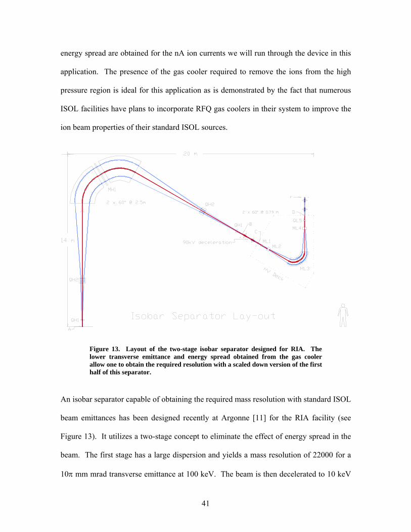
Figure 13. Layout of the two-stage isobar separator designed for RIA. The lower transverse emittance and energy spread obtained from the gas cooler
n isobar separator capable of obtaining the required mass resolution with standard ISOL
allow one to obtain the required resolution with a scaled down version of the first half of this separator.
A
beam emittances has been designed recently at Argonne [11] for the RIA facility (see
Figure 13). It utilizes a two-stage concept to eliminate the effect of energy spread in the
beam. The first stage has a large dispersion and yields a mass resolution of 22000 for a
10π mm mrad transverse emittance at 100 keV. The beam is then decelerated to 10 keV
41

and passed through a second stage with a dispersion and radius scaled down by the
momentum ratio with respect to the initial stage. This second dispersion cancels out the
effect of the energy spread on the first dispersion (smaller dispersion but with
proportionately increased momentum spread) while only decreasing the total mass
resolution by 10%. The result is an overall mass resolution of 20000 for a 10π mm mrad
transverse emittance at 100 keV and an initial energy spread of ± 10 eV. This ambitious
design can achieve high resolution with a much poorer quality beam compared to similar
devices, but at the cost of a footprint of 14 meters by 20 meters.
This isobar separator is much too large to fit on a high voltage platform but the
normalized emittance of the beams that will be extracted from the gas cooler system will
be a factor of 4.7 times smaller than those for which the RIA isotope separator was
designed. This implies that scaling down the first section of this separator by a factor of
4.7 to a radius of 0.53 meter would yield a mass resolution of 22000 similar to that of the
first section of the RIA isobar separator if no energy spread is present. The gas cooler
beam energy spread of less than 1 eV does not require a second stage for correction as
long as the total accelerating voltage is above 44 kV. The design that has therefore been
judged optimal for the present application is to use an ion optics similar to that used in
the first part of the RIA isobar separator, but scaled down by roughly a factor of 4 to a
bending radius of 0.6 meter. The bending angle is still 120 degrees with two 60 degrees
bending magnet separated by a multipole element to correct for aberrations. With a total
acceleration voltage of 50 kV, this yields a mass resolution in excess of 20000 with slit
size of 0.25 mm. This fulfills our performance requirements with the gas catcher, isobar
42

separator and focal point all fitting on the gas catcher high voltage platform. The main
technical requirements to achieve this resolution are the homogeneity and stability of the
magnetic field integral across the magnet poles and the high voltage stability. Both are
well within performance level that have been achieved by other devices in the past.
F. Beam dump
ne important consideration for the operation of the upgrade within ATLAS is to
O
minimize the spread of radioactive contamination outside of the gas catcher high voltage
platform. Essentially all activity extracted from the gas catcher will be transported to the
isobar separator and then dispersed in its focal plane with a dispersion of just above 5
meters. A movable slit assembly at the focal plane will let the mass of interest go
through and stop the isobars and neighboring masses. The assembly will also include a
wire scanner (with current read out at normal beam intensity and secondary electron
detection at very low intensity) to tune the isobar separator. The full assembly must be
shielded and serviceable. In addition, isotopes of masses further away from the mass of
interest will be implanted on liners surrounding the beam envelope in the dispersive
plane. These liners should be removable (and possibly disposable) for servicing of the
isobar separator. The gamma activity collected on these liners will be shielded by the
magnet themselves and thin additional shielding outside if required. Thin high-Z
shielding around the vacuum chamber leading to the focal plane will be used to deal with
the gamma activity from the accumulated fission fragments.
43
G. High voltage platform
he injection of the radioactive ions into the charge-state breeder requires that the
imilarly, for optimum capture in the ECR plasma, the few volts difference between the
T
potential at which the gas catcher is operated be the same as that of the plasmas in the
ECR breeder. The potential of the ECR-1 high voltage platform is set by the acceleration
in ATLAS which requires up to about 250 kV of acceleration before injection into the PII
linac for the heaviest of the beams considered in this upgrade. The ECR source is
typically operated at 15 kV above the ECR platform voltage to enable beam formation
before the magnetic analysis in the 90 degrees magnet on the platform. On the gas
catcher high voltage platform, the isobar separator magnet and optics need to be sitting at
50 kV below the gas catcher potential. For optimum operation, the isobaric separation
sets a requirement for the 50 kV between the gas catcher and the isobar separator system
to be stable at the one volt level.
S
gas catcher and the ECR breeder potentials must also be stable at the volt level. These
requirements are best met by monitoring or comparing the smallest voltage differences
possible; this yields higher precision and minimizes the potential for over-voltage across
electronic equipment. It was therefore decided that the gas catcher high voltage platform
would be tied electrically to the ECR-1 high voltage with a low voltage power supply that
will be used to fine tune the difference in potential for optimum trapping in the charge
breeder. The low-voltage supply will be properly protected against overvoltages. The
gas catcher and gas cooler system will be tied to the high voltage of the platform. This
44
eliminates the possible influence of voltage ripple on separate high voltages. The isobar
separator section on the gas catcher platform will be biased by a –50 kV supply with
respect to the gas catcher potential. The beam will then be de-celerated to the source
platform voltage as the beam transitions from the gas-catcher platform to the charge-
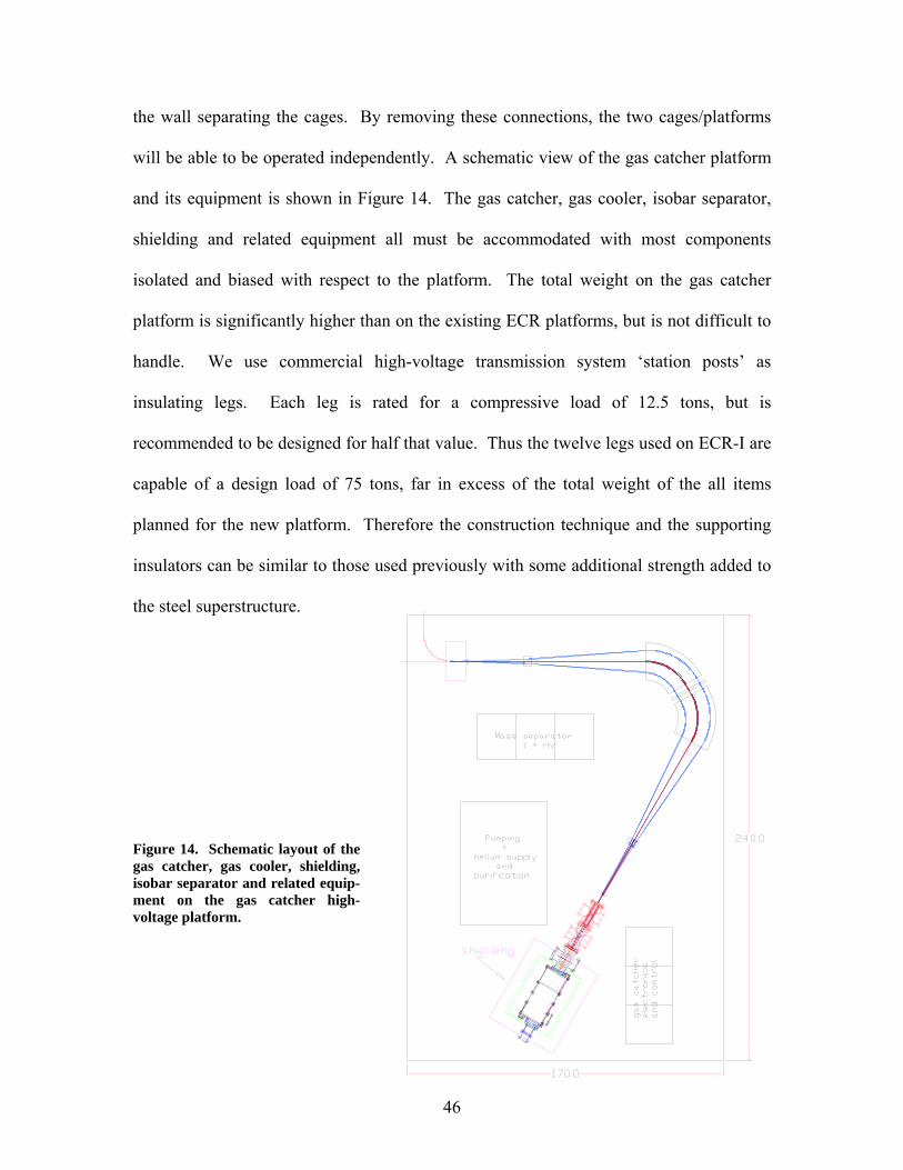
breeder platform. These voltage and energy relationships are shown in Figure 16. This
high-voltage will be measured absolutely and locked by feedback from a high-precision
temperature-stabilized high voltage divider. These relationships between the different
voltages minimize the potential for the destruction of sensitive equipment in the case of
failure of any component. The two physical platforms will be at a potential difference of
roughly 15 kV that will allow for a relatively simple transfer section between both. The
high voltage power supply biasing the ECR source will provide bias to the gas catcher
platform and gas catcher. Electrical power for the gas catcher and gas cooler electronics
and pumps on the new platform will be provided by a 300kV 100 kVA isolation
transformer. A second smaller isolation transformer rated for roughly 30 kVA at 50kV,
referenced to the platform, will provide power to the isobar separator magnets and related
equipment. All connections between the two platforms will be removable to allow
operation of the ECR-1 source in a standalone mode and for beam development from the
fission source separately from injection into the charge state breeder.
The gas catcher platform will have a size of 20 ft by 14 ft, similar to that of the existing
ECR platforms. It will be located 8 ft away from the ECR-1 platform. An independent
cage will be built adjacent to the existing cage surrounding the ECR-1 platform to host
the new platform. The links and transfer line between both platforms will pass through
45
the wall separating the cages. By removing these connections, the two cages/platforms
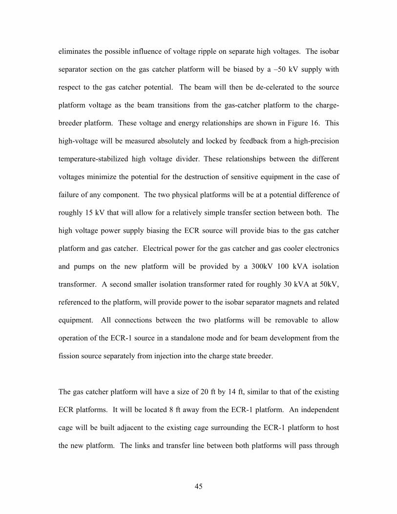
will be able to be operated independently. A schematic view of the gas catcher platform
and its equipment is shown in Figure 14. The gas catcher, gas cooler, isobar separator,
shielding and related equipment all must be accommodated with most components
isolated and biased with respect to the platform. The total weight on the gas catcher
platform is significantly higher than on the existing ECR platforms, but is not difficult to
handle. We use commercial high-voltage transmission system ‘station posts’ as
insulating legs. Each leg is rated for a compressive load of 12.5 tons, but is
recommended to be designed for half that value. Thus the twelve legs used on ECR-I are
capable of a design load of 75 tons, far in excess of the total weight of the all items
planned for the new platform. Therefore the construction technique and the supporting
insulators can be similar to those used previously with some additional strength added to
the steel superstructure.
Fgas c
igure 14. Schematic layout of the atcher, gas cooler, shielding,
isobar separator and related equip-ment on the gas catcher high-voltage platform.
46

H. Source region transport system and unaccelerated beam transport
The transport system will take the selected activity from the output of the isobar separator
and deliver it either to the charge-state breeder on the neighboring high voltage platform
or to a diagnostics station off the platform at ground potential. The transport for these
low energy beams is performed with electrostatic steering and focusing elements. This
allows the beamline tuning to be mass independent. An acceleration column is required
on the section leading to the diagnostics station. Diagnostics along the transport system
must include Faraday cups for the highest intensity beams, beam profilers that can
operate with low intensity beams and beta detectors to monitor activity. See section “K”
below for a discussion of the diagnostics required for transport to the ATLAS accelerator
and on to the experimental stations.
I. Diagnostics station
Tuning of the gas catcher/gas cooler/isobar separator ensemble must be optimized to
obtain maximum yield. The multi-parameter space requires proper diagnostics. Clear
identification of the isotopes is critical. This can be achieved with a tape station, a high
efficiency beta counter and a gamma ray detector. By collecting the activity for a fixed
time and moving it in front of the beta detector one can determine the total radioactive
beam intensity and measure the decay lifetime which identifies the dominant isotope and
contaminants. Additional information can be obtained when needed from gamma ray
identification. The accumulated activity is removed by the tape transport system after
47

each measurement cycle allowing for clean conditions for each new measurement. The
cycling time is typically fast enough to allow tuning of the extracted yield with the beta
detection as “live” diagnostics.
In addition, part of the physics program envisaged for this upgrade involves study with
stopped or low energy beams of radioactive ions. The diagnostics station will receive
such beams at the full ion source intensity, independently of the rest of the ATLAS
accelerator. An electrostatic switchyard in front of the diagnostics station will allow
other more specialized detection systems to receive the beams of interest for these low-
energy studies.
J. Charge state breeder
Over the past eight years a variation on a standard ECR ion source, known as the charge-
breeder ECR ion source has been developed, largely led by groups in Grenoble [6]. This
work is based on the realization that the plasma potential, formed in the central region of
a standard ECR ion source, can be used to capture low charge-state injected ions and then
subsequently ionize those captured ions further by electron bombardment in the plasma.
This capture process is possible only if the incoming ions are near to the source axis, to
avoid reflection of the ions by the magnetic mirror, and if the ions can be slowed to
energies below a few eVs, to allow capture by the shallow plasma potential. Capture of
the ions is required since the ions must be trapped for 10-100 ms in order to strip them to
48

high charge states. Single passage transit times across the source are a small fraction of
this stripping time so the ions must be confined for many equivalent transit times.
The precise beam properties required for capture into the charge breeder are not well
defined, but energy spreads of 2-4 eV and transverse emittances of <100π mm*mr are
needed typically for good capture. Lower emittance beams should be helpful for
injection through the mirror by minimizing mirror reflection from angular momentum
conservation. The beam properties of the fission fragments emerging from the helium
gas catcher are expected to exceed these general requirements and therefore are expected
to be efficiently matched into the charge breeder.
Figure 15. Cross-section view of the Phoenix ECR charge breeder.
A cross-section view of a charge-breeder ECR source is shown in Figure 15. The major
modifications to convert a standard ECR source into a charge breeder source are to
provide the necessary opening and beam optics into the plasma regions for delivering the
49
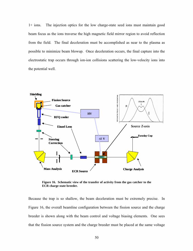
1+ ions. The injection optics for the low charge-state seed ions must maintain good
beam focus as the ions traverse the high magnetic field mirror region to avoid reflection
from the field. The final deceleration must be accomplished as near to the plasma as
possible to minimize beam blowup. Once deceleration occurs, the final capture into the
electrostatic trap occurs through ion-ion collisions scattering the low-velocity ions into
the potential well.
SS Fission Source
Einzel Lens
Steering Correction
Mass Analysis Charge Analysis
Faraday Cup
HV
±δ V
Source Z-axis
hielding
Gas catcher
RFQ cooler
ECR Source
Fission Source
Einzel Lens
Steering Correction
Mass Analysis Charge Analysis
Faraday Cup
HV
±δ V
Source Z-axis
hielding
Gas catcher
RFQ cooler
ECR Source
Figure 16. Schematic view of the transfer of activity from the gas catcher to the ECR charge state breeder.
Because the trap is so shallow, the beam deceleration must be extremely precise. In
Figure 16, the overall beamline configuration between the fission source and the charge
breeder is shown along with the beam control and voltage biasing elements. One sees
that the fission source system and the charge breeder must be placed at the same voltage
50
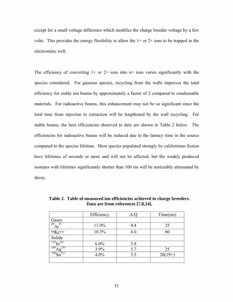
except for a small voltage difference which modifies the charge breeder voltage by a few
volts. This provides the energy flexibility to allow the 1+ or 2+ ions to be trapped in the
electrostatic well.
The efficiency of converting 1+ or 2+ ions into n+ ions varies significantly with the
species considered. For gaseous species, recycling from the walls improves the total
efficiency for stable ion beams by approximately a factor of 2 compared to condensable
materials. For radioactive beams, this enhancement may not be so significant since the
total time from injection to extraction will be lengthened by the wall recycling. For
stable beams, the best efficiencies observed to date are shown in Table 2 below. The
efficiencies for radioactive beams will be reduced due to the latency time in the source
compared to the species lifetime. Most species populated strongly by californium fission
have lifetimes of seconds or more and will not be affected, but the weakly produced
isotopes with lifetimes significantly shorter than 100 ms will be noticeably attenuated by
decay.
Table 2. Table of measured ion efficiencies achieved in charge breeders. Data are from references [7,8,14].
Efficiency A/Q Time(ms) Gases 40
Ar9+ 11.9% 4.4 25
84Kr14+ 10.3% 6.0 60 Solids 115In18+ 6.0% 5.8 109Ag19+ 3.9% 5.7 25 120Sn22+ 4.0% 5.5 20(19+)
51

For this project, we plan to modify the existing ATLAS 10 GHz ECR-I source to function
as a charge breeder. A cross-section view of the present ECR-I is shown in Figure 17.
The modifications required for ECR-I are focused on the ‘injection’ end of the source, the
normal location of material feeds, biased disks, RF waveguide, and other diagnostic and
utility function. These components will be rearranged to allow a one or two stage
deceleration electrode assembly to control the 1+ beam as it decelerates to a near stop.
A preliminary design of the modified ECR-I source is shown in Figure 18.
Figure 17. Present ECR-I 10 GHz Ion Source
For most cases, long-term contamination of the interior of the source will be rather
modest. The longest-lived species directly produced by the fission of 252Cf is 144Ce
(284.6d) and is produced with rather low intensity (2.7E+5 s-1) while the next longest
lived species is 140Ba (12.75d) produced at a rate of 1.4E+6 s-1. About half of those will
be lost in the ECR source and at saturation they correspond to total radiation levels of
52

1.4 mrem/hr and 15 mrem/hr respectively at 30 cm, if concentrated at one point rather
than distributed over the interior of the source. Similar radiation levels are reached with
the long-lived daughters of shorter-lived isotopes with the total decay rate never
exceeding the activity deposition rate so that the maximum activity level that could be
expected is about 100 mrem/hr for an isotope with a week lifetime along the decay chain.
Generally speaking, maintenance-requiring access to the interior of an ECR source is
rare, but it does occur. Even though the level of activity requires only careful monitoring
and maintenance procedures, it may be desirable to install a liner in ECR-I to allow easy
cleanup of the source and do necessary maintenance. ECR-I has operated in the past
successfully with a stainless steel liner and we see no significant issues with using such a
liner when deemed necessary. But in general we do not believe this will be necessary.
The injection beamline from the mass separator to the charge breeder will consist of a 90
degree bending magnet and electrostatic focusing lenses to match the radioactive 1+
beam into the source. Beam current and beam size diagnostics, using secondary electron
emission and MCP detection, will be mounted at the image point of the analyzing
magnet, just ahead of injection into the source. A simple blocking shield will protect this
sensitive electronics from beam leaking from the operating ECR source. In order to
provide the necessary space for a 90 degrees bending magnet as part of the beam
transport from the fission source to the charge-breeder, ECR-I will be moved up to the
entrance waist point of the extraction beamline analyzing magnet. This configuration has
been employed already at a number of ECR source facilities throughout the world and so
should pose no serious concerns. In fact, such close geometry is an improved design
53

from a space charge concern (keep in mind that the source will run mostly on support gas
and so space charge effects near the source extraction region are a significant issue).
The development of the charge breeder source will need to progress in parallel with the
gas catcher fission source development. Although the physical changes needed to
convert ECR-I to a charge breeder are relatively modest, significant development work
such as learning how to optimally operate an ECR source as a charge breeder will be
required. A separate stable-beam 1+ ion source will be used to develop the proper
operating modes for the source. We estimate that a full man-year of effort from the
existing ECR group is necessary to implement the design changes and to undertake
charge breeding studies during the 2 years of this project. This would be followed by the
permanent expansion of the group by one person to continue operation and development.
Figure 18. ECR-1 modifications required for charge-breeder operation.
54
The modifications required for ECR-I may affect the charge-state distribution slightly,
but otherwise the source can continue to operate as a stable beam source as well as a
charge breeder. But once construction begins, which will take only 4-8 weeks, then
commissioning of the source as a charge breeder will require a focused effort. Therefore
the source will not be available for at least six months after the modifications to allow
these development efforts. Initial work will be with stable beams from simple 1+ ion
sources such as surface ionization sources. Then once the fission fragment system is
commissioned, additional development time will be necessary to learn how to best
operate the total system. Thus during the second year of construction, ECR-I will be
available for stable beams operation with ATLAS on a very limited basis. Once fully
commissioned there will continue to be some development effort, but at this point ECR-I
will return to being schedulable for stable as well as radioactive beams.
K. ATLAS and diagnostics improvements
ATLAS operations has considerable experience with low-intensity beams. Programs
with radioactive beams, such as 18F, 56Ni, 56Co, and with accelerator mass spectroscopy
(AMS) have required the development of techniques for acceleration of beams with little
or no diagnostics possible. In general the accelerator is tuned with a ‘guide’ beam, that
is a beam with nearly the same charge-to-mass ratio (q/m) as the weak beam of interest.
A small scale factor is then applied to that tuned condition to provide the required tune
for the weak beam. Reliance on the researcher’s detection system has been important up
to now in optimizing the tune configuration.
55
This general approach will still be the primary method of accelerator setup for these
fission fragment beams, but additional weak-beam diagnostics will be needed to provide
a more flexible, and experiment-independent tuning algorithm. Low-intensity profile
monitors have been developed as part of the RIA activity and will be added to the
ATLAS diagnostics system to provide both beam profile information and beam current
measurements. These profile monitors will also serve as Faraday cups at those locations.
To reduce costs other ion counters (“Faraday cups”) will be installed at other locations in
the beam transport system. The costs for these systems included in the budget assume
that only the beamlines to the spectrograph, FMA, Gammasphere and (hopefully) the
proposed solenoid spectrometer will be developed initially as part of this construction
project. More stations can be implemented later as demand warrants. The low-intensity
diagnostics stations necessary for this configuration are shown in Figure 20.
ATLAS uses silicon solid-state detectors systems routinely for beam tuning by elastically
scattering the primary beam at small forward angles in order to measure beam energy and
time. These systems will be modified to allow insertion at zero degrees, which in
combination with attenuators will allow direct observation of the radioactive beam
properties. Later, development of high-pressure gas detectors and other detector systems
will be pursued. This work is not necessary to the successful completion of this project
but is seen as part of ongoing improvement efforts that are a natural part of any operating
facility. Funds for this effort would be expected to come from the facility operating and
capital equipment funds.
56

Figure 19. ATLAS floor plan showing the planned locations for low-intensity profile monitors and beam current monitors. This plan assumes beam delivery to four target stations. Finally, the transmission through the accelerator system must be optimized. ATLAS
itself, with its large acceptance superconducting cavities, is a very high transmission
accelerator. The only expected limitation to the transmission is due to the theoretical
limit of 85% efficiency for the multiharmonics buncher and the 90% transmission of the
buncher grids. In everyday operation at ATLAS, the beam current delivered to
experiments is usually limited by what targets can tolerate or by administrative radiation
limits. Work is underway to improve the transmission in the low-energy beam transport
section from ECR-I to PII. We believe presently achieved transmission of around 70%
from ECR-I can be improved significantly. Costs for this activity are not part of this
project, but are rather viewed as routine on-going accelerator development.
57

VI. Operation Issues
ATLAS is the premier low-energy stable beam accelerator in the US. It serves a large
community of users and it is important that the implementation of this upgrade does not
result in a significant increase in down time for the facility. The connection of the
radioactive beam ion source to the ATLAS accelerator is only through the ECR-1 ion
source. The ECR-2 ion source operation is not disturbed by the upgrade and will be used
for experiments requiring high beam intensity. ECR-1, after its modification to a charge
breeder, will remain operational as an ECR source in standalone mode. The installation
of the gas catcher high voltage platform in an independent cage allows it and the ECR-I
high voltage platforms to be essentially independent during construction or while low-
energy experiments are performed out of the gas catcher platform. As a result, the
current flexibility and low downtime available with two sources for stable beam
operation will be maintained. The ability to operate and tune the gas catcher and isobar
separator independently from the rest of the facility is a distinct advantage. The
connections between the gas catcher and ECR-1 platforms will be installed only for
experiments with accelerated neutron-rich beams. Tuning of the capture of the
radioactive beam into the charge breeder can be performed while a stable beam
experiment is running out of the ECR-2 source, in a fashion similar to the development of
stable beams in ECR-1 while experiments are running out of ECR-2, a procedure
frequently used today. High-voltage relationships between the different components are
also such that the ECR-1 voltage can be varied to optimize transmission through the
58
accelerator without modifying the voltage relationship between ECR-1 and the gas
catcher so that injection into the charge state breeder does not have to be retuned.
Similarly, tuning on the gas catcher platform will not require retuning of ATLAS. The
upgrade will provide beams that would normally be obtained with the two-accelerator
method (one to produce the activity, one to post-accelerate), but will require running only
one accelerator. The only significant difference on the schedule will then be the longer
expected tuning time for the accelerator because of the lower beam intensities. Because
of the high efficiency of the overall facility, the total inventory of radioactive material is
kept to a minimum and the radioactivity that can be lost inside the accelerator (see
section VII) is not high enough to warrant modifications of the maintenance and repair
procedures now in place.
VII. Safety Issues
The proposed ATLAS californium upgrade increases the radioactive beam capabilities at
ATLAS by adding a source of short-lived neutron-rich isotopes to the facility. This
addition does not change the classification of the ATLAS facility since the threshold for a
category 3 nuclear facility is 3.2 Ci of 252Cf according to DOE Std. 1027-92. (The
Physics Division does maintain a 100 milligram Pu-Be neutron source that will need to
be placed in a special isolation container so that the Division does not exceed a Category
III facility.) A significant revision to the ATLAS Safety Assessment Document will be
required to address the new hazards and changes in facility configuration. In addition
59

new operating procedures and additional training for the ATLAS staff will be required to
ensure safe operation of the facility.
Most changes to the facility will be on a new high-voltage platform that will host the gas
catcher containing the high-intensity fission source and some low-energy beam
preparation equipment. Two high-voltage platforms are in operation at ATLAS for the
existing ECR sources and the required safety procedures, including a number of
redundant grounding procedures to allow access to the platforms, are in place. There are
additional electrical hazards associated with the operation of a large gas catcher which
have also been dealt with before at ATLAS. Safe procedures for the standard operation of
the new device, based on engineering controls, administrative controls and proper
training, will be devised based on this expertise. Those procedures will undergo
independent safety reviews during the project, and be approved by the safety authorities
at Argonne before operation. These are standard procedures at ATLAS for any new
major piece of equipment.
The californium upgrade project also introduces a significant potential hazard with the
presence of a 1 Ci 252Cf source that raises issues of shielding and possible contamination.
All fissionable activity and the bulk (>99%) of the radioactive fission products will be
confined to the gas catcher high-voltage platform. Simulations and reports from other
facilities indicate that the 1 Ci fission source, unshielded, would yield a neutron radiation
field of just over 4 rem/hr at 1 meter and a gamma field of 250 mrem/hr at the same
distance. ATLAS can generate similar radiation fields, but those disappear when the
60

accelerator is turned off; with the fission source they remain until the source has decayed
away. ATLAS has expertise with sources of that magnitude in the existing research
program with radioactive beams, but these are generally shorter-lived beta-emitters (18F
sources used in the past had strength of up to 1 Ci) that emit no neutrons. Argonne has
expertise and facilities capable of dealing with sources of neutron emitters of this
magnitude. The main radiation safety tasks are to ensure safe preparation, transport and
installation of the source without introducing contamination, and proper shielding and
containment of activity during operation and maintenance. The transport cask and
installation mechanism have been described earlier, the calculations used to determine the
required shielding are briefly described below.
A first estimate of the required shielding was obtained by requiring a total radiation field
at 30 cm from the shielding surface of about 1 mrem/hr. Using the MCNP code and a
proper description of the source, we obtained for a spherical geometry and shells of 5 cm
of steel, 60 cm of 5% borated polyethylene and 5 cm of lead fields of 0.3 mrem/hr
neutrons, 0.2 mrem/hr gamma (from the neutron capture), 0.6 mrem/hr gamma (direct),
for a total of 1.1 mrem/hr at 1 meter from the source (30 cm from the shielding). These
numbers essentially set the requirements for the cask used for the transport of the source
and for the permanent shielding on the sides of the gas catcher.
For a more detailed understanding of the shielding required, especially at the entrance
side of the gas catcher where the source will be inserted, the geometry shown in Figure
20 was investigated. A particular concern was that the shielding permanently present
61

around the gas catcher be sufficient to allow access for limited time periods to the
vacuum sealing port used to bring in the source. As shown above in section III.C, the
cask is in place during the installation of the source and vacuum sealing, and remains in
place after installation to provide additional shielding. If the sealing mechanism were
however to get stuck, manual intervention might be necessary. Under these conditions
and with the shielding shown in Figure 20 (3/4” steel, 10” borated polyethylene and 2”
lead), the radiation levels one would be exposed to working on the sealing would be 137
mrem/hr neutrons, 1.5 mrem/hr gamma from capture and 10 mrem/hr gamma direct for a
total of 150 mrem/hr at 30 cm from the accessible surface. This would make such
emergency repair operation possible. In addition, for this critical back region that we
would like to remain thin, a new shielding material made of a mixture of Colamenite and
Epoxy resin could be used instead of borated polyethylene to reduce the radiation fields
further by about a factor of 2. This possibility is being investigated.
Figure 20. Views of the geometry used in the radiation calculations with the MCNP code. The color coding is: Red – helium gas, Orange- steel, Green – aluminum, Blue – borated polyethylene, Yellow – lead. The source is located on the axis and at the back of the gas catcher.
62

For all other gas catcher repair or maintenance operations, the source would be retrieved
into the cask that would then be closed. The only radioactivity left to be dealt with in this
case is that from the fission fragments accumulated in the gas catcher. After months of
operation the inside of the gas catcher would reach levels of about 5 rem/hr of low energy
betas and 30 mrem/hr of gammas. The low energy betas are easily shielded from but the
gamma field is a more serious concern. To alleviate this difficulty it was decided that the
gas catcher design has to be highly modular so that sections could be easily removed and
replaced in cases where major maintenance or repair is required. A complete spare
would be available and the appropriate spare section would replace a failed one. This
failed section would then be transported to a hot lab for repair or packing for disposal, if
necessary. It is likely that maintenance requiring only a few hours total work might be
possible without removal and spare replacement.
During these maintenance activities, the vacuum system will be opened and thus made
common with the general room. The maintenance activities make the possibility of
spreading contamination out into the space around the gas-catcher beamline a possibility.
It will therefore be necessary to create an isolation ‘room’ around this maintenance area,
complete with a HEPA-filtered air system, radiation monitors, and other standards for a
contamination area. It is proposed to use a temporary “tent” to define the area. The
structure will involve a permanent metal frame on which tent-like walls will be attached,
creating an isolated space. During normal operation some of the tent walls will be rolled
up providing easy access to the platform region. When it is required to open the vacuum
63

system and therefore create the possibility of contamination, the tent walls are closed, and
a HEPA filtration system installed to filter and exchange the air in the tent. Such a
system has been designed by ANL Waste Management personnel. The estimated costs of
the tent system is less than $5000. The entire maintenance operation is then monitored
by Waste Management and ESH personnel. Disposal of any contaminated components,
up and including the entire gas catcher assembly in a worst-case accident, will be handled
by ANL Waste Management personnel. For such a worst-case accident requiring
disposal of the fission source, its cask and the gas catcher, the estimated cost is $100,000
but no significant spreadable contamination is envisioned even under this worst-case
scenario.
Radiation levels in the gas catcher area will be monitored at all time by neutron and
gamma monitors interfaced to the ARIS radiation monitoring system currently in use at
ATLAS. Any operation that requires opening the vacuum system around the gas catcher
or working for extended periods of time on the platform will be monitored by health
physics personnel once the proper radiation work permit for the intervention has been
granted.
Most radioactive ions not extracted as beam from the gas catcher will coat the walls of
the gas catcher except for the neutrals from volatile species such as xenon and krypton
that will be extracted and pumped out in the first section of the RFQ cooler. The pump
exhaust will go through an HEPA filter that will remove most contamination while the
inert species (such as radioactive xenon isotopes that will be present at the 107 atoms per
64
second level) will be released. These noble gases do not present a health risk and are
considered safe to exhaust. Of course an annual report of our releases is required and
that is handled by the Laboratory ESH support groups.
The radioactivity that will reach other components of the facility is much smaller in
magnitude. Of the order of 107 radioactive ions per second will be transported to the
ECR-1 high voltage platform and injected into the charge state breeder. Activity build up
of up to a few hundred µCi will occur after long periods of running. Removing the
breeder liner should eliminate radiation exposure and allow normal maintenance on other
components on that platform. The beams sent through the accelerator for post-
acceleration will have intensities of up to 106 particles per second. A beam dump
collecting the full beam intensity for a week would accumulate roughly 25 µCi of short-
lived activity that would then decay over time. This activity is not beyond present levels
experienced at ATLAS with high intensity stable beams on thick targets. Losses along
the beamline will be minimal and the activity accumulated at these points will scale
accordingly. No additional precautions or procedures besides those currently in place are
expected to be required along the accelerator and beamlines for the radioactive beams.
The radioactive wastes generated by normal operation and maintenance (such as the
HEPA filters) will be handled in a fashion identical to how such wastes are handled now
at ATLAS. Every component removed from any experimental area at ATLAS is treated
as low-level radioactive waste that is dealt with at fairly low cost by the existing
infrastructure. It is not expected that the total amount of such waste will be significantly
65

changed by the upgrade. Even the components in direct contact with the californium
source would fall in this category since the lifetime of californium is too short too fall
under the transuranic waste category.
Finally, the very effective containment of most radioactivity to one high-voltage platform
will minimize the eventual decommissioning costs. Essentially all accumulated
radioactive inventory will be inside the gas catcher and the vacuum vessel and beam
dump of the isobar separator. There will be some additional contamination in the
transport cask and, to a smaller degree, in the liner of the charge state breeder. We expect
no changes to the status of the remainder of ATLAS, and as a result, no changes to the
decommissioning costs of the bulk of the ATLAS facility.
VIII. Budget
The proposed ATLAS californium source upgrade is based in large part on technology
developed and already in use at Argonne and, as a result, for most components we have
recent purchasing or fabrication cost information available. These costs have been
escalated for inflation where necessary. Engineering designs and production of machine
drawings will be carried out in the Physics Division. Fabrication of these custom
designed components will be done by Argonne or commercial vendors depending on
costs, time scales and quality assurance considerations. The estimated costs of individual
sub-assemblies are listed in Table 3. The contingency associated with each budget item
varies between 10% and 30%, depending on the uncertainties associated with individual
66

costs. Assembly and testing will be carried out by a combination of Physics Division
staff members and additional personnel whose support is requested within this proposal.
Overhead rates are estimated based on the rates which apply at Argonne National
Laboratory during FY2005. The overhead rate on procured items is 9.2%, whereas the
rates on laboratory services varies between 22.6% and 29%.
67
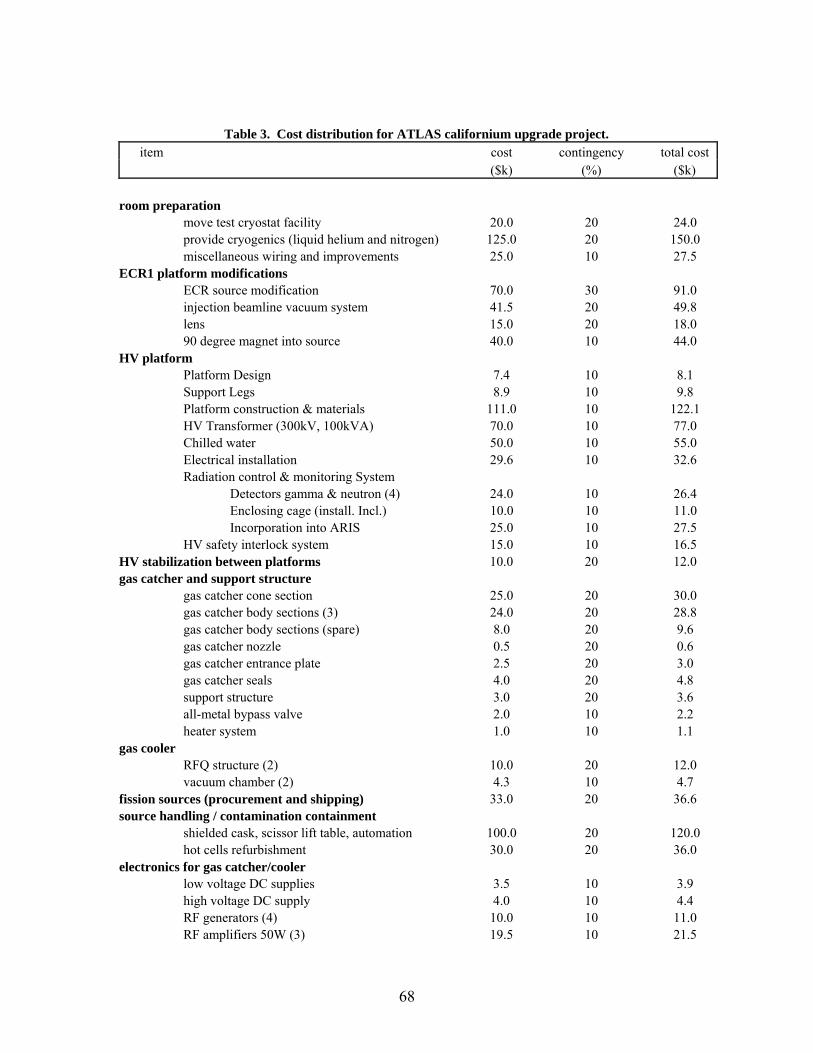
Table 3. Cost distribution for ATLAS californium upgrade project. item cost contingency total cost
($k) (%) ($k) room preparation move test cryostat facility 20.0 20 24.0 provide cryogenics (liquid helium and nitrogen) 125.0 20 150.0 miscellaneous wiring and improvements 25.0 10 27.5 ECR1 platform modifications ECR source modification 70.0 30 91.0 injection beamline vacuum system 41.5 20 49.8 lens 15.0 20 18.0 90 degree magnet into source 40.0 10 44.0 HV platform Platform Design 7.4 10 8.1 Support Legs 8.9 10 9.8 Platform construction & materials 111.0 10 122.1 HV Transformer (300kV, 100kVA) 70.0 10 77.0 Chilled water 50.0 10 55.0 Electrical installation 29.6 10 32.6 Radiation control & monitoring System Detectors gamma & neutron (4) 24.0 10 26.4 Enclosing cage (install. Incl.) 10.0 10 11.0 Incorporation into ARIS 25.0 10 27.5 HV safety interlock system 15.0 10 16.5 HV stabilization between platforms 10.0 20 12.0 gas catcher and support structure gas catcher cone section 25.0 20 30.0 gas catcher body sections (3) 24.0 20 28.8 gas catcher body sections (spare) 8.0 20 9.6 gas catcher nozzle 0.5 20 0.6 gas catcher entrance plate 2.5 20 3.0 gas catcher seals 4.0 20 4.8 support structure 3.0 20 3.6 all-metal bypass valve 2.0 10 2.2 heater system 1.0 10 1.1 gas cooler RFQ structure (2) 10.0 20 12.0 vacuum chamber (2) 4.3 10 4.7 fission sources (procurement and shipping) 33.0 20 36.6 source handling / contamination containment shielded cask, scissor lift table, automation 100.0 20 120.0 hot cells refurbishment 30.0 20 36.0 electronics for gas catcher/cooler low voltage DC supplies 3.5 10 3.9 high voltage DC supply 4.0 10 4.4 RF generators (4) 10.0 10 11.0 RF amplifiers 50W (3) 19.5 10 21.5
68
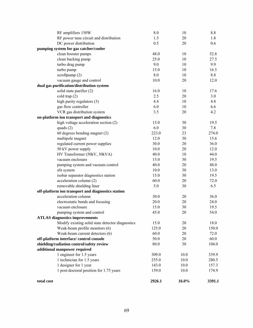
RF amplifiers 150W 8.0 10 8.8 RF power tune circuit and distribution 1.5 20 1.8 DC power distribution 0.5 20 0.6 pumping system for gas catcher/cooler clean booster pumps 48.0 10 52.8 clean backing pump 25.0 10 27.5 turbo drag pump 9.0 10 9.9 turbo pump 15.0 10 16.5 scrollpump (2) 8.0 10 8.8 vacuum gauge and control 10.0 20 12.0 dual gas purification/distribution system solid state purifier (2) 16.0 10 17.6 cold trap (2) 2.5 20 3.0 high purity regulators (3) 4.4 10 4.8 gas flow controller 6.0 10 6.6 VCR gas distribution system 3.5 20 4.2 on-platform ion transport and diagnostics high voltage acceleration section (2) 15.0 30 19.5 quads (2) 6.0 30 7.8 60 degrees bending magnet (2) 223.0 23 274.0 multipole magnet 12.0 30 15.6 regulated current power supplies 30.0 20 36.0 50 kV power supply 10.0 20 12.0 HV Transformer (50kV, 30kVA) 40.0 10 44.0 vacuum enclosure 15.0 30 19.5 pumping system and vacuum control 40.0 20 48.0 slit system 10.0 30 13.0 isobar separator diagnostics station 15.0 30 19.5 acceleration column (2) 60.0 20 72.0 removable shielding liner 5.0 30 6.5 off-platform ion transport and diagnostics station acceleration column 30.0 20 36.0 electrostatic bends and focusing 20.0 20 24.0 vacuum enclosure 15.0 30 19.5 pumping system and control 45.0 20 54.0 ATLAS diagnostics improvements Modify existing solid state detector diagnostics 15.0 20 18.0 Weak-beam profile monitors (6) 125.0 20 150.0 Weak-beam current detectors (6) 60.0 20 72.0 off-platform interface/ control console 50.0 20 60.0 shielding/radiation control/safety review 80.0 30 104.0 additional manpower required 1 engineer for 1.5 years 309.0 10.0 339.9 1 technician for 1.5 years 255.0 10.0 280.5 1 designer for 1 year 143.0 10.0 157.3 1 post-doctoral position for 1.75 years 159.0 10.0 174.9 total cost 2926.1 16.0% 3391.1
69
IX. Schedule and Manpower
The schedule for this project is based on the assumption that funding will become
available at the start of FY2006. The time required to complete construction of the
project is expected to be two years. The design, procurement, fabrication, installation,
assembly, and commissioning will follow the schedule as illustrated in Figure 21. To
achieve this schedule, the project will need to be funded over a two year period. In the
first year, FY2006, we request funding at the level of $1900k with the remainder, $1491,
provide in FY2007.
Minimizing the disruption of ATLAS operation is a prime concern in the schedule. The
new high-voltage platform and gas catcher/cooler assemblies will be constructed and
tested independently of ATLAS operation. During the construction phase for ECR-I
(about 9 months into the project), the source will be removed from normal ATLAS
operation. Following restart of ECR-I, much of its running will be to commission the
source as a charge breeder using simple stable-beam 1+ sources, such as surface
ionization sources, for the test beams. During this period ECR-I may return to limited
use for ATLAS operation as needed. The reconfiguration of ECR-I and the initial restart
of the source is expected to take approximately three months.
Connection of both high-voltage platforms will be performed once both components are
ready which is about 1 year into the project. Two safety reviews of the project are
70
proposed during the construction and installation phase with an additional final review
before the 1 Ci californium source is received.
Safety reviews will be conducted regularly throughout the construction, installation and
commissioning phases. Three permit-to-operate reviews are identified as milestones on
the project schedule, one prior to each stage of introducing increased amounts of
radioactive material.
The Physics Division manpower and additional engineering and design effort necessary
for this project is estimated to be slightly over 10.5 man-years, including a project
manager and technical director. This does not include machine shop and electronics shop
construction effort for components contained in Table 3. Of the total effort identified in
Table 4, 4.33 man-years is assumed to come from existing ATLAS staff.
71
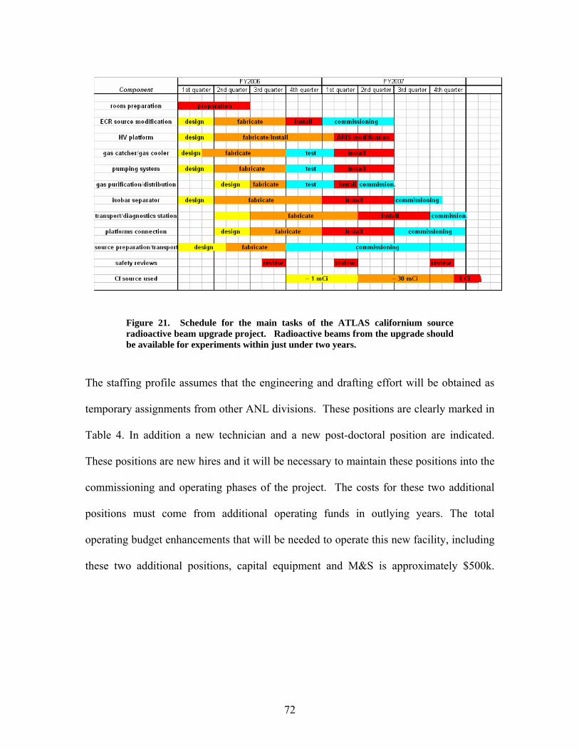
Figure 21. Schedule for the main tasks of the ATLAS californium source radioactive beam upgrade project. Radioactive beams from the upgrade should be available for experiments within just under two years.
The staffing profile assumes that the engineering and drafting effort will be obtained as
temporary assignments from other ANL divisions. These positions are clearly marked in
Table 4. In addition a new technician and a new post-doctoral position are indicated.
These positions are new hires and it will be necessary to maintain these positions into the
commissioning and operating phases of the project. The costs for these two additional
positions must come from additional operating funds in outlying years. The total
operating budget enhancements that will be needed to operate this new facility, including
these two additional positions, capital equipment and M&S is approximately $500k.
72

Table 4. 252Cf upgrade staffing levels during construction
FY2006 FY2007 FY2008 Total
man-month
Person 1st Qrtr 2nd Qrtr 3rd Qrtr 4th Qrtr 1st Qrtr 2nd Qrtr 3rd Qrtr 4th Qrtr
New Designer* ▬▬ ▬▬ ▬▬ ▬▬ ▬▬ ▬▬ ▬▬ Start 12 New Engineer* ▬▬ ▬▬ ▬▬ ▬▬ ▬▬ ▬▬ ▬▬ comm 18 New Post Doc ▬▬ ▬▬ ▬▬ ▬▬ ▬▬ ▬▬ ission 21 New Technician ▬▬ ▬▬ ▬▬ ▬▬ ▬▬ ing 18 Redirect existing ECR Group
▬▬ ▬▬ ▬▬ ▬▬ ▬▬ ▬▬ ▬▬ of 12
Project Manager ▬▬ ▬▬ ▬▬ ▬▬ ▬▬ ▬▬ ▬▬ full 8 Technical Director ▬▬ ▬▬ ▬▬ ▬▬ ▬▬ ▬▬ ▬▬ system 8 Computer Control (ATLAS staff)
▬▬ ▬▬ ▬▬ ▬▬ ▬▬ ▬▬ 6
Other ATLAS staff (ARIS, diagnostics, electronics, procedures, training)
▬▬ ▬▬ 18
Other ANL staff ▬▬ ▬▬ ▬▬ ▬▬ ▬▬ ▬▬ ▬▬ 6 Total 127
* Designer and Engineer to be ‘purchased’ from other ANL divisions for period required. ▬▬▬▬ Full time ▬▬▬▬ Part time
73

X. Expected Performance
The estimated yields both at low energy and after acceleration for the more abundant
252Cf fission fragments are given below. The independent yields (percentage of direct
fission branch) are color coded to indicate the more intense beams. Low energy beams
are available at energies from about 10 keV up to 250-500 keV depending on the charge
state extracted from the gas catcher system. Accelerated beams are available from these
energies up to the maximum energy the ATLAS facility will be able to deliver after the
current energy upgrade, roughly from ion source energy up to 12-16 MeV/u for the light
fission fragments and up to 10-13 MeV/u for the heavy fragments.
The yield estimate uses the measured direct yield from a 1 Ci californium source.
It assumes a 50% stopping fraction in the gas catcher, 45% extraction efficiency out of
the gas catcher /gas cooler assembly, charge state breeding efficiency of 10% for gaseous
species and 5% for solids, decay losses at all steps of the process (assuming 20 ms for the
extraction/cooling time and 30 ms for charge breeding), 85% bunching efficiency and
90% transmission efficiency (other than bunching) through ATLAS. No significant
losses are expected from the charge-state distribution after the catcher since the fission
fragments will emerge predominantly in a single charge state (1+ or 2+).
74

Nuclide t1/2 independent low energy accelerated
yield beam beam (ions/sec) (ions/sec)
83As 13.4 s 2.32E-02 6.3E+04 2.3E+0383Se 22.3m 9.01E-03 2.4E+04 8.9E+0284As 5.5 s 2.19E-02 5.9E+04 2.2E+0384Se 3.3 m 2.55E-02 6.9E+04 2.5E+0385As 2.03 s 2.60E-02 7.0E+04 2.5E+03
85Se-m 19 s 3.75E-02 1.0E+05 3.7E+0385Se 39 s 3.75E-02 1.0E+05 3.7E+0385Br 2.87m 1.92E-02 5.2E+04 1.9E+0386As 0.9 s 9.35E-03 2.5E+04 8.9E+0286Se 15.0 s 6.70E-02 1.8E+05 6.6E+03
86Br-m 4.5 s 2.10E-02 5.6E+04 2.1E+0386Br 55.5 s 2.10E-02 5.7E+04 2.1E+0387Se 5.6 s 7.11E-02 1.9E+05 7.0E+0387Br 55.9 s 1.10E-01 3.0E+05 1.1E+0487Kr 1.27 h 2.24E-02 6.0E+04 4.4E+0388Se 1.50 s 4.42E-02 1.2E+05 4.3E+0388Br 16.4 s 1.69E-01 4.6E+05 1.7E+0488Kr 2.84 h 8.81E-02 2.4E+05 1.7E+0489Se 0.41 s 1.53E-02 4.0E+04 1.4E+0389Br 4.37 s 1.50E-01 4.0E+05 1.5E+0489Kr 3.15 m 1.74E-01 4.7E+05 3.4E+0489Rb 15.4 m 2.00E-02 5.4E+04 2.0E+0390Br 1.9 s 1.09E-01 2.9E+05 1.1E+0490Kr 32.3 s 3.35E-01 9.0E+05 6.6E+04
90Rb-m 4.3 m 7.48E-02 2.0E+05 7.4E+0390Rb 2.6 m 1.75E-02 4.7E+04 1.7E+0391Br 0.54 s 4.14E-02 1.1E+05 3.8E+0391Kr 8.6 s 3.16E-01 8.5E+05 6.2E+0491Rb 58.0 s 2.24E-01 6.0E+05 2.2E+0491Sr 9.5 h 1.78E-02 4.8E+04 1.8E+0392Br 0.34 s 1.20E-02 3.1E+04 1.1E+0392Kr 1.84 s 2.36E-01 6.3E+05 4.6E+0492Rb 4.48 s 3.47E-01 9.3E+05 3.4E+0492Sr 2.71 h 8.14E-02 2.2E+05 8.1E+0393Kr 1.29 s 1.30E-01 3.5E+05 2.5E+0493Rb 5.85 s 5.03E-01 1.4E+06 4.9E+0493Sr 7.4 m 2.36E-01 6.4E+05 2.3E+0493Y 10.2 h 1.07E-02 2.9E+04 1.1E+0394Kr 0.21 s 4.89E-02 1.2E+05 8.1E+0394Rb 2.73 s 4.54E-01 1.2E+06 4.4E+0494Sr 1.25 m 5.47E-01 1.5E+06 5.4E+0494Y 18.7 m 5.96E-02 1.6E+05 5.9E+0395Kr 0.78 s 1.10E-02 2.9E+04 2.1E+0395Rb 0.377s 2.68E-01 6.9E+05 2.4E+04
75

95Sr 25.1s 7.67E-01 2.1E+06 7.6E+0495Y 10.3 m 1.98E-01 5.3E+05 2.0E+04
96Rb 0.199s 1.27E-01 3.1E+05 1.0E+0496Sr 1.06 s 8.88E-01 2.4E+06 8.5E+04
96Y -m 9.6 s 4.91E-01 1.3E+06 4.8E+0496Y 6.2 s 5.45E-02 1.5E+05 5.4E+03
97Rb 0.169s 3.44E-02 8.4E+04 2.7E+0397Sr 0.42 s 6.02E-01 1.6E+06 5.4E+0497Y 3.76 s 8.70E-01 2.3E+06 8.5E+0497Zr 16.8 h 1.66E-01 4.5E+05 1.6E+0498Rb 0.107s 8.20E-03 1.9E+04 5.7E+0298Sr 0.65 s 3.71E-01 9.8E+05 3.5E+04
98Y -m 2.1 s 6.43E-01 1.7E+06 6.3E+0498Y 0.59 s 6.43E-01 1.7E+06 6.0E+0498Zr 30.7 s 5.87E-01 1.6E+06 5.8E+0498Nb 2.9 s 1.62E-02 4.3E+04 1.6E+0399Sr 0.269s 1.35E-01 3.4E+05 1.2E+0499Y 1.47 s 1.15E+00 3.1E+06 1.1E+0599Zr 2.2 s 1.25E+00 3.3E+06 1.2E+05
99Nb-m 2.6 m 1.07E-01 2.9E+05 1.1E+0499Nb 15.0 s 9.33E-03 2.5E+04 9.2E+02100Sr 0.201s 3.52E-02 8.7E+04 2.9E+03100Y 0.73 s 7.78E-01 2.1E+06 7.3E+04100Zr 7.1 s 2.06E+00 5.5E+06 2.0E+05
100Nb-m 3.0 s 2.85E-01 7.7E+05 2.8E+04100Nb 1.5 s 2.85E-01 7.6E+05 2.8E+04100Mo stable 1.48E-02 4.0E+04 1.5E+03101Y 0.43 s 3.36E-01 8.7E+05 3.0E+04101Zr 2.1 s 2.20E+00 5.9E+06 2.1E+05101Nb 7.1 s 1.30E+00 3.5E+06 1.3E+05101Mo 14.6 m 8.93E-02 2.4E+05 8.8E+03102Y 0.36 s 8.26E-02 2.1E+05 7.4E+03102Zr 2.9 s 1.45E+00 3.9E+06 1.4E+05102Nb 1.3 s 2.04E+00 5.4E+06 2.0E+05102Mo 11.3 m 4.64E-01 1.3E+06 4.6E+04103Y 0.260s 1.78E-02 4.5E+04 1.5E+03103Zr 1.3 s 8.43E-01 2.2E+06 8.1E+04103Nb 1.5 s 3.06E+00 8.2E+06 3.0E+05103Mo 1.13 m 1.47E+00 4.0E+06 1.5E+05103Tc 54 s 5.66E-02 1.5E+05 5.6E+03104Zr 1.2 s 2.24E-01 6.0E+05 2.1E+04104Nb 4.8 s 2.15E+00 5.8E+06 2.1E+05104Mo 60 s 2.83E+00 7.6E+06 2.8E+05104Tc 18.2 m 4.31E-01 1.2E+06 4.3E+04105Zr 0.493s 3.91E-02 1.0E+05 3.6E+03105Nb 3.0 s 9.99E-01 2.7E+06 9.8E+04105Mo 36 s 3.02E+00 8.2E+06 3.0E+05105Tc 7.6 m 2.10E+00 5.7E+06 2.1E+05105Ru 4.44 h 6.83E-02 1.8E+05 6.8E+03106Nb 1.0 s 4.41E-01 1.2E+06 4.2E+04
76

106Mo 8.4 s 3.47E+00 9.3E+06 3.4E+05106Tc 36 s 2.19E+00 5.9E+06 2.2E+05106Ru 1.020y 2.08E-01 5.6E+05 2.1E+04107Nb 0.766s 9.02E-02 2.4E+05 8.5E+03107Mo 3.5 s 2.01E+00 5.4E+06 2.0E+05107Tc 21.2 s 3.63E+00 9.8E+06 3.6E+05107Ru 3.8 m 8.72E-01 2.4E+06 8.6E+04107Rh 21.7 m 1.58E-02 4.3E+04 1.6E+03108Nb 0.242s 1.02E-02 2.6E+04 8.6E+02108Mo 1.5 s 6.67E-01 1.8E+06 6.4E+04108Tc 5.1 s 3.33E+00 9.0E+06 3.3E+05108Ru 4.5 m 1.98E+00 5.3E+06 2.0E+05
108Rh-m 5.9 m 5.73E-02 1.5E+05 5.7E+03108Rh 17 s 5.73E-02 1.5E+05 5.7E+03109Mo 1.41 s 1.48E-01 3.9E+05 1.4E+04109Tc 1.4 s 1.89E+00 5.0E+06 1.8E+05109Ru 34.5 s 2.99E+00 8.1E+06 3.0E+05
109Rh-m 50 s 2.54E-01 6.9E+05 2.5E+04109Rh 1.34 m 6.52E-01 1.8E+06 6.5E+04110Mo 2.77 s 2.31E-02 6.2E+04 2.3E+03110Tc 0.83 s 8.55E-01 2.3E+06 8.1E+04110Ru 15 s 3.62E+00 9.8E+06 3.6E+05
110Rh-m 29 s 6.75E-01 1.8E+06 6.7E+04110Rh 3.1 s 6.72E-01 1.8E+06 6.6E+04110Pd stable 6.05E-02 1.6E+05 6.0E+03111Tc 1.98 s 1.76E-01 4.7E+05 1.7E+04111Ru 1.5 s 2.26E+00 6.0E+06 2.2E+05111Rh 11 s 2.46E+00 6.6E+06 2.4E+05
111Pd-m 5.5 h 1.71E-01 4.6E+05 1.7E+04111Pd 23.4 m 1.21E-01 3.3E+05 1.2E+04112Tc 0.431s 2.29E-02 5.9E+04 2.1E+03112Ru 4.5 s 9.39E-01 2.5E+06 9.2E+04112Rh 4 s 2.39E+00 6.4E+06 2.3E+05112Pd 20.04h 7.45E-01 2.0E+06 7.4E+04112Ag 3.13 h 3.60E-02 9.7E+04 3.6E+03113Ru 2.7 s 2.13E-01 5.7E+05 2.1E+04113Rh 0.9 s 1.95E+00 5.2E+06 1.9E+05113Pd 1.64 m 2.39E+00 6.5E+06 2.4E+05
113Ag-m 1.14 m 1.96E-01 5.3E+05 1.9E+04113Ag 5.3 h 2.94E-02 7.9E+04 2.9E+03114Ru 8.14 s 1.90E-02 5.1E+04 1.9E+03114Rh 1.8 s 5.60E-01 1.5E+06 5.4E+04114Pd 2.48 m 1.82E+00 4.9E+06 1.8E+05114Ag 4.6 s 9.13E-01 2.5E+06 9.0E+04114Cd stable 1.98E-02 5.3E+04 2.0E+03115Rh 0.99 s 1.71E-01 4.5E+05 1.6E+04115Pd 47 s 1.70E+00 4.6E+06 1.7E+05
115Ag-m 18.7 s 5.38E-01 1.5E+06 5.3E+04115Ag 20 m 4.39E-01 1.2E+06 4.3E+04
115Cd-m 44.6 d 4.10E-02 1.1E+05 4.1E+03
77

115Cd 2.228d 1.23E-02 3.3E+04 1.2E+03116Rh 0.7 s 2.26E-02 6.0E+04 2.1E+03116Pd 12.7 s 8.19E-01 2.2E+06 8.1E+04
116Ag-m 10.5 s 5.37E-01 1.4E+06 5.3E+04116Ag 2.68 m 6.50E-01 1.8E+06 6.4E+04116Cd stable 9.83E-02 2.7E+05 9.7E+03117Pd 5 s 2.92E-01 7.9E+05 2.9E+04
117Ag-m 5.3 s 5.15E-01 1.4E+06 5.1E+04117Ag 1.22 m 5.00E-01 1.3E+06 4.9E+04
117Cd-m 3.4 h 1.47E-01 4.0E+05 1.5E+04117Cd 2.49 h 4.38E-02 1.2E+05 4.3E+03118Pd 2.4 s 1.27E-01 3.4E+05 1.2E+04
118Ag-m 2.4 s 2.94E-01 7.9E+05 2.9E+04118Ag 4.0 s 2.97E-01 8.0E+05 2.9E+04118Cd 50.3 m 2.72E-01 7.3E+05 2.7E+04119Pd 1.76 s 8.49E-03 2.3E+04 8.2E+02119Ag 2.1s 1.93E-01 5.2E+05 1.9E+04
119Cd-m 2.20 m 8.91E-02 2.4E+05 8.8E+03119Cd 2.69 m 8.91E-02 2.4E+05 8.8E+03120Ag 1.23 s 7.95E-02 2.1E+05 7.6E+03120Cd 50.8 s 1.56E-01 4.2E+05 1.5E+04121Ag 0.78 s 1.90E-02 5.0E+04 1.8E+03121Cd 13.5 s 9.79E-02 2.6E+05 9.7E+03122Cd 5.3 s 8.34E-02 2.2E+05 8.2E+03123Cd 2.09 s 3.34E-02 8.9E+04 3.2E+03124Cd 1.24 s 1.10E-02 2.9E+04 1.1E+03124In 3.18 s 9.46E-03 2.5E+04 9.3E+02126In 1.63 s 7.98E-03 2.1E+04 7.7E+02126Sn 1.e5y 1.77E-02 4.8E+04 1.8E+03
127Sn-m 4.15 m 2.85E-02 7.7E+04 2.8E+03127Sn 2.12 h 6.97E-02 1.9E+05 6.9E+03128Sn 59.1 m 1.75E-01 4.7E+05 1.7E+04
128Sb-m 10.1 m 9.48E-03 2.6E+04 9.4E+02129Sn-m 6.9 m 1.18E-01 3.2E+05 1.2E+04
129Sn 2.4 m 2.88E-01 7.8E+05 2.9E+04129Sb 4.40 h 1.72E-01 4.6E+05 1.7E+04130In 0.29 s 1.02E-02 2.6E+04 8.9E+02130Sn 3.7 m 3.62E-01 9.8E+05 3.6E+04
130Sb-m 6.5 m 2.80E-01 7.6E+05 2.8E+04130Sb 38.4 m 1.64E-01 4.4E+05 1.6E+04130Te stable 3.07E-02 8.3E+04 3.0E+03131Sn 39 s 2.96E-01 8.0E+05 2.9E+04131Sb 23.0 m 9.95E-01 2.7E+06 9.9E+04
131Te-m 1.35 d 2.36E-01 6.4E+05 2.3E+04131Te 25.0 m 6.95E-02 1.9E+05 6.9E+03132Sn 40 s 1.38E-01 3.7E+05 1.4E+04
132Sb-m 2.8 m 5.11E-01 1.4E+06 5.1E+04132Sb 4.2 m 7.06E-01 1.9E+06 7.0E+04132Te 3.26 d 7.77E-01 2.1E+06 7.7E+04132I 2.28 h 2.11E-02 5.7E+04 2.1E+03
78
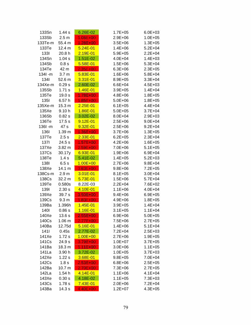
133Sn 1.44 s 6.26E-02 1.7E+05 6.0E+03133Sb 2.5 m 1.06E+00 2.9E+06 1.0E+05
133Te-m 55.4 m 1.28E+00 3.5E+06 1.3E+05133Te 12.4 m 5.24E-01 1.4E+06 5.2E+04133I 20.8 h 2.19E-01 5.9E+05 2.2E+04
134Sn 1.04 s 1.51E-02 4.0E+04 1.4E+03134Sb 0.8 s 5.58E-01 1.5E+06 5.3E+04134Te 42 m 2.35E+00 6.3E+06 2.3E+05134I -m 3.7 m 5.83E-01 1.6E+06 5.8E+04
134I 52.6 m 3.31E-01 8.9E+05 3.3E+04134Xe-m 0.29 s 2.60E-02 6.6E+04 4.5E+03
135Sb 1.71 s 1.46E-01 3.9E+05 1.4E+04135Te 19.0 s 1.78E+00 4.8E+06 1.8E+05135I 6.57 h 1.85E+00 5.0E+06 1.8E+05
135Xe-m 15.3 m 2.25E-01 6.1E+05 4.4E+04135Xe 9.10 h 1.86E-01 5.0E+05 3.7E+04136Sb 0.82 s 3.02E-02 8.0E+04 2.9E+03136Te 17.5 s 9.12E-01 2.5E+06 9.0E+04136I -m 47 s 9.32E-01 2.5E+06 9.2E+04
136I 1.39 m 1.36E+00 3.7E+06 1.3E+05137Te 2.5 s 2.33E-01 6.2E+05 2.3E+04137I 24.5 s 1.57E+00 4.2E+06 1.6E+05
137Xe 3.82 m 2.59E+00 7.0E+06 5.1E+05137Cs 30.17y 6.93E-01 1.9E+06 6.9E+04138Te 1.4 s 5.41E-02 1.4E+05 5.2E+03138I 6.5 s 1.00E+00 2.7E+06 9.8E+04
138Xe 14.1 m 3.63E+00 9.8E+06 7.2E+05138Cs-m 2.9 m 3.01E-01 8.1E+05 3.0E+04
138Cs 32.2 m 5.73E-01 1.5E+06 5.7E+04139Te 0.580s 8.22E-03 2.2E+04 7.6E+02139I 2.30 s 4.10E-01 1.1E+06 4.0E+04
139Xe 39.7 s 3.50E+00 9.4E+06 6.9E+05139Cs 9.3 m 1.83E+00 4.9E+06 1.8E+05139Ba 1.396h 1.45E-01 3.9E+05 1.4E+04140I 0.86 s 1.16E-01 3.1E+05 1.1E+04
140Xe 13.6 s 2.55E+00 6.9E+06 5.0E+05140Cs 1.06 m 2.77E+00 7.5E+06 2.7E+05140Ba 12.75d 5.16E-01 1.4E+06 5.1E+04141I 0.45s 2.77E-02 7.2E+04 2.5E+03
141Xe 1.72 s 1.00E+00 2.7E+06 1.9E+05141Cs 24.9 s 3.79E+00 1.0E+07 3.7E+05141Ba 18.3 m 1.11E+00 3.0E+06 1.1E+05141La 3.90 h 3.72E-02 1.0E+05 3.7E+03142Xe 1.22 s 3.68E-01 9.8E+05 7.0E+04142Cs 1.8 s 2.53E+00 6.8E+06 2.5E+05142Ba 10.7 m 2.70E+00 7.3E+06 2.7E+05142La 1.54 h 4.14E-01 1.1E+06 4.1E+04143Xe 0.30 s 4.18E-02 1.1E+05 7.3E+03143Cs 1.78 s 7.43E-01 2.0E+06 7.2E+04143Ba 14.3 s 4.40E+00 1.2E+07 4.3E+05
79

143La 14.1 m 1.05E+00 2.8E+06 1.0E+05143Ce 1.38 d 1.64E-02 4.4E+04 1.6E+03144Xe 1.2 s 1.16E-02 3.1E+04 2.2E+03144Cs 1.01 s 5.49E-01 1.5E+06 5.2E+04144Ba 11.4 s 3.37E+00 9.1E+06 3.3E+05144La 40.7 s 1.86E+00 5.0E+06 1.8E+05144Ce 284.6d 1.01E-01 2.7E+05 1.0E+04145Cs 0.59 s 1.49E-01 3.9E+05 1.4E+04145Ba 4.0 s 2.06E+00 5.5E+06 2.0E+05145La 24 s 2.51E+00 6.8E+06 2.5E+05145Ce 3.00 m 3.47E-01 9.4E+05 3.4E+04146Cs 0.322s 2.58E-02 6.6E+04 2.3E+03146Ba 2.20 s 9.81E-01 2.6E+06 9.5E+04146La 6.3 s 2.39E+00 6.4E+06 2.4E+05146Ce 13.5 m 1.01E+00 2.7E+06 1.0E+05146Pr 24.2 m 3.07E-02 8.3E+04 3.0E+03147Ba 0.892s 2.50E-01 6.6E+05 2.4E+04147La 4.02 s 1.94E+00 5.2E+06 1.9E+05147Ce 56 s 1.91E+00 5.2E+06 1.9E+05147Pr 13.4 m 1.81E-01 4.9E+05 1.8E+04148Ba 0.64 s 4.80E-02 1.3E+05 4.5E+03148La 1.1 s 9.86E-01 2.6E+06 9.4E+04148Ce 56 s 2.35E+00 6.3E+06 2.3E+05148Pr 2.27 m 5.41E-01 1.5E+06 5.4E+04148Nd stable 1.33E-02 3.6E+04 1.3E+03149La 1.10 s 2.34E-01 6.2E+05 2.2E+04149Ce 5.2 s 1.50E+00 4.0E+06 1.5E+05149Pr 2.3 m 9.29E-01 2.5E+06 9.2E+04149Nd 1.72 h 5.80E-02 1.6E+05 5.7E+03150La 0.608s 5.51E-02 1.4E+05 5.1E+03150Ce 4.4 s 9.41E-01 2.5E+06 9.2E+04150Pr 6.2 s 1.30E+00 3.5E+06 1.3E+05150Nd stable 1.45E-01 3.9E+05 1.4E+04151Ce 1.0 s 2.92E-01 7.7E+05 2.8E+04151Pr 22.4 s 1.07E+00 2.9E+06 1.1E+05151Nd 12.4 m 5.60E-01 1.5E+06 5.5E+04151Pm 1.183d 2.15E-02 5.8E+04 2.1E+03152Ce 3.1 s 7.45E-02 2.0E+05 7.3E+03152Pr 3.2 s 6.96E-01 1.9E+06 6.8E+04152Nd 11.4 m 8.28E-01 2.2E+06 8.2E+04
152Pm-m 7.5 m 6.06E-02 1.6E+05 6.0E+03152Pm 4.1 m 6.06E-02 1.6E+05 6.0E+03153Ce 1.47 s 1.02E-02 2.7E+04 9.8E+02153Pr 4.3 s 2.61E-01 7.0E+05 2.6E+04153Nd 28.9 s 7.99E-01 2.2E+06 7.9E+04153Pm 5.4 m 2.17E-01 5.9E+05 2.1E+04154Pr 2.3 s 5.33E-02 1.4E+05 5.2E+03154Nd 25.9 s 4.19E-01 1.1E+06 4.1E+04
154Pm-m 2.7 m 2.55E-01 6.9E+05 2.5E+04154Pm 1.7 m 2.98E-01 8.0E+05 2.9E+04
80
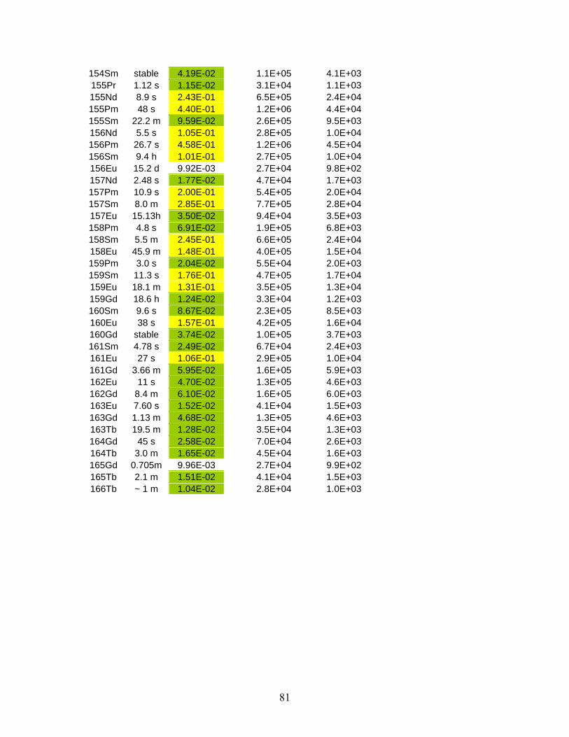
154Sm stable 4.19E-02 1.1E+05 4.1E+03155Pr 1.12 s 1.15E-02 3.1E+04 1.1E+03155Nd 8.9 s 2.43E-01 6.5E+05 2.4E+04155Pm 48 s 4.40E-01 1.2E+06 4.4E+04155Sm 22.2 m 9.59E-02 2.6E+05 9.5E+03156Nd 5.5 s 1.05E-01 2.8E+05 1.0E+04156Pm 26.7 s 4.58E-01 1.2E+06 4.5E+04156Sm 9.4 h 1.01E-01 2.7E+05 1.0E+04156Eu 15.2 d 9.92E-03 2.7E+04 9.8E+02157Nd 2.48 s 1.77E-02 4.7E+04 1.7E+03157Pm 10.9 s 2.00E-01 5.4E+05 2.0E+04157Sm 8.0 m 2.85E-01 7.7E+05 2.8E+04157Eu 15.13h 3.50E-02 9.4E+04 3.5E+03158Pm 4.8 s 6.91E-02 1.9E+05 6.8E+03158Sm 5.5 m 2.45E-01 6.6E+05 2.4E+04158Eu 45.9 m 1.48E-01 4.0E+05 1.5E+04159Pm 3.0 s 2.04E-02 5.5E+04 2.0E+03159Sm 11.3 s 1.76E-01 4.7E+05 1.7E+04159Eu 18.1 m 1.31E-01 3.5E+05 1.3E+04159Gd 18.6 h 1.24E-02 3.3E+04 1.2E+03160Sm 9.6 s 8.67E-02 2.3E+05 8.5E+03160Eu 38 s 1.57E-01 4.2E+05 1.6E+04160Gd stable 3.74E-02 1.0E+05 3.7E+03161Sm 4.78 s 2.49E-02 6.7E+04 2.4E+03161Eu 27 s 1.06E-01 2.9E+05 1.0E+04161Gd 3.66 m 5.95E-02 1.6E+05 5.9E+03162Eu 11 s 4.70E-02 1.3E+05 4.6E+03162Gd 8.4 m 6.10E-02 1.6E+05 6.0E+03163Eu 7.60 s 1.52E-02 4.1E+04 1.5E+03163Gd 1.13 m 4.68E-02 1.3E+05 4.6E+03163Tb 19.5 m 1.28E-02 3.5E+04 1.3E+03164Gd 45 s 2.58E-02 7.0E+04 2.6E+03164Tb 3.0 m 1.65E-02 4.5E+04 1.6E+03165Gd 0.705m 9.96E-03 2.7E+04 9.9E+02165Tb 2.1 m 1.51E-02 4.1E+04 1.5E+03166Tb ~ 1 m 1.04E-02 2.8E+04 1.0E+03
81

XI. References 1. A.H. Wuosmaa et al., Proposal for a solenoidal spectrometer to study reactions with
short-lived beams. submitted to DOE in October 2004. 2. D.C. Radford et al., Physics with heavy neutron-rich RIBs at the HRIBF, Eur. Phys. J.
A15, 171 (2002). 3. H.-J. Kluge, W. Nörtershäuser, Lasers for nuclear physics, Spectrochimica Acta Part
B 58, 1031 (2003). 4. F. Le Blanc et al., Charge radii and nuclear moments around Sn-132, Nucl. Phys. A
734, 437 (2004). 5. J.M.G. Levins et al., First On-Line Laser Spectroscopy of Radioisotopes of a
Refractory Element, Phys. Rev. Lett. 82, 2476 (1999). 6. R. Geller, C. Tamburella, and J.L. Belmont, The ISOL-MAFIOS Source, Rev. Sci
Instrum., 67(3), 1281(1996). 7. T. Lamy et al., Charge state breeding applications with the ECR PHOENIX source:
From low to high current production, Rev. Sci. Instrum, 73(2), 717(2002). 8. T. Lamy, et al., Charge Breeeding Method Results with the Phoenix Booster ECR Ion
Source, Proceedings EPAC 2002, Paris France, June 3-7, 2002, pp. 1724-1726. 9. G. Savard et al., Development and Operation of Gas Catchers to Thermalize Fusion-
evaporation and Fragmentation Products, Nucl. Instr. & Meth. B204, 582 (2003). 10. F. Herfurth et al., A linear radiofrequency ion trap for accumulation, bunching, and
emittance improvement of radioactive ion beams, Nucl. Instr. & Meth. A469, 254 (2001).
11. M. Portillo, J.A. Nolen and T.A. Barlow, Design layout of an isobar separator based on 5th order calculations, in Proceedings of the 2001 IEEE Particle Accelerator Conference, edited by P. Lucas and S. Webber, Chicago, IL, June 18-22 2001, pp. 3015-3017.
12. R.A. Anderl et al., Ion-source development at the 252Cf ISOL facility, Nucl. Instr. and Meth. B26 (1987) 333.
13. R.A. Anderl et al., A laboratory-scale shielded cell for 252Cf, Proc. 27th Conf. Remote Systems Technology (1979) p. 347.
14. F. Wenander, Charge Breeding Techniques, Nuclear Physics A746, 40c (2004).
82