Embed Size (px)
Citation preview

C.P. No. 789
MINISTRY OF AVIATION
AERONAUTICAL RESEARCH COUNCIL
CURRENT PAPERS
Proposals for+ an Integrated Wind Tunnel-Flight Dynamics
Simulator System bY
L. 1. l3eecham, W. L. Walters and D. W. Partridge
LONDON: HER MAJESTY’S STATIONERY OFFICE
I965
PRICE 10s 6d NET


U.D.C. No. 533.6.071 : 518.5 : 533.6.013
C,P, No.789
November, 1962
PROPOSALS FOR AN INTEGRATED WIND TUNNEL-FLIGHT DYNKZCS SIMULATOR SYSmR'I
SUh~Y --
A design is considered in which the wind tunnel is an integral part of a system suitable for the simulation of the behaviour of aircraft and missiles in flight. The static aerodynamic loads on a wind tunnel model, mounted on a conventional quadrant support, are measured and combined with continuously computed gravitational, inertial and aerodynamic da&.ng loads, the model orientation to the flight path being correctly maintained throughout.
The computer elements comprise a small analogue unit for the on-line correction of the wind tunnel data, and a D.D.A, unit consisting of GCRSAIBs for tha kinexatic simulation and wind tunnel control,
--- --
Replaces i3.A.i:. 'I'ech. Note FTo. Aero 2852 - A.R.C. 24-681
----


LIST OF CO$JTENTS
I INTRODUCTION
2 GENKRAL APPROACH
3 ON-LINE DATA CORRECTION
4 KINEMATICS
4.1 Analogue differential analyser
Ic.1 .I Integrators and multiplier3 4.1.2 Amplifier3 4.1.3 Initial condition setting
4.2 Digital dif'fercntisl analyser
5 CONTROL OP TiIIZ WIND TT.WEL 1'1ODEL ORIE%TATIOIJ TO 'LTIE WIND VECTOR
6 INPUT AND OUTPUT IREQUIRE!,~I?TS
7 ACCURACY OP SIXULATION
8 IiEniIom fxrumoN 0P ~.110mi CONTROL SURFACES
9 I]i~p~I,i~TIT~ ;l~~ 0;~
ACI(NOYVLXDGEfTS
LIST OF SYMBOLS
LIST OF' KWERENCES
TABLE 1 - CORSAIR integrator utilisation in the various stages
ILLUSTRATIONS - Figs.l-13
DETACHABLE ABSTRAC'I' CARDS
PaRe
4
4
5
7
9
9
99
10
12
45
16
17
18
18
18
19
21
.
LIST OF ILLUST,?ATIONS Fig.
Analogue on-line data correction notwork for linear interaction terms 1
Analogue on-line data correction network for linear and cross- product terms 2
Schematic disgrwx of clectro-mechanic21 analogue simulator 3
A 5%integrator CORSAIR installation 4
Schematic dingrrun of wind tunnel/flight dynamics simulator 5
-2-

LIST OF ILLUSTRATIOI'X3 (ConC'd~
Integrator networks for stage 4
(4 04 (0) (a)
(4 (f)
Force block
Moment block
Direction cosines generation
Transformation from Cartesian body axes to polar tunnel axes
(i) Normalised velocities and accelerations
(ii) Setting angles and pulse frequency control functions
Pulse frequency control
Transformation from body to earth axes 6
Flow diagram for stage l+ 7
Fig.
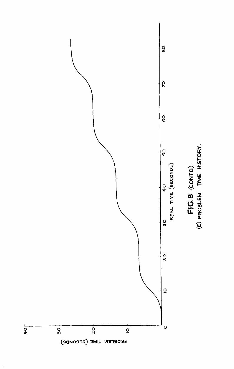
Typical records using pulse frequency control technique
(a) Applied to incidence, CT
(b) Applied to roll. angle, X
(c) Problem time history 8
Schematic layout of hydraulic actuation of incidence quadrant and roll drive 9
Notarised control actuator IO
Calibration of potentiometer 11
Cartesian missile model embodying remotely operated control surfaces
Sketch of suggested stin CT and wing dzivo arrangements for a twist-and-steer missile model
12
13
-3-
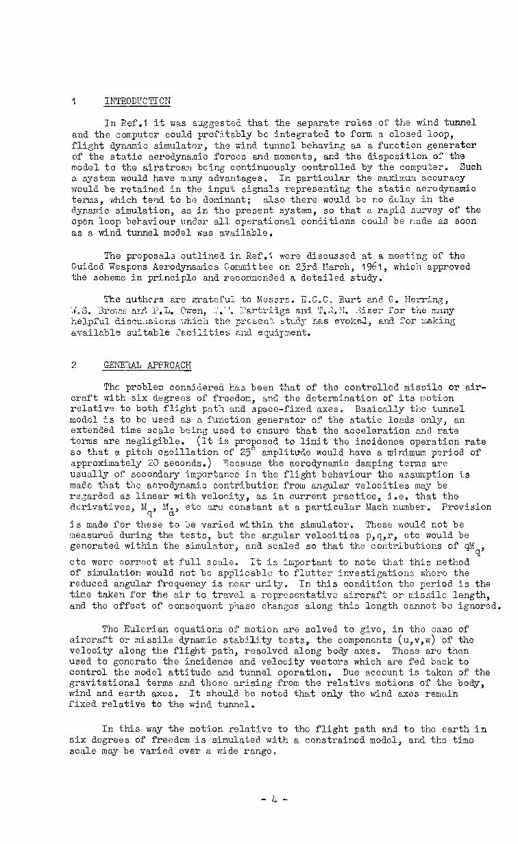
1 IYJTRODITCTIOTJ
In Ref.1 it was s.Jggested that the separate roles of the wind tunnel and the computer could profitably bc integrated to form a closed loop, flight dynamic simulator, the wind tunnel behaving as a function generator of the static aerodynalnic forces and moments, and the disposition of the model to the airstream being continuously controlled by the computer. Such a system would have many advantages. In particular the maximum accuracy would be retained in the input signals representing the static aerodynamic terms, which tend to be dominant; also there would be no delay in the dynamic simulation, as in the present system, so that a rapid survey of the open loop behaviour under all operational conditions could be made as soon as a wind tunnel model was available.
The proposals outlined in Ref.1 wore discussed at a meeting of the Guided Weapons Aerodynamics Committee on 23rd Narch, 1961, which approved the scheme in principle and recommended a detailed study.
The authcrs are grateful to !!4essrs. EOG.C, Burt and G. Herring, ;,r' .S. 3ro:m and P,L. &en, I.'.-', ;.'artrilge and. 'T.3.H. ,-Zzer for the many helpful discussions which the Drtsent study has evokeJ, and for liLaking available suitable facilities and equipment,
2 GENEXAL APPROACH
The problem considered has been that of the controlled missile or air- craft with six degrees of freedom, and the determination of its motion relative to both flight path and space-fixed axes. Basically the tunnel model is to be used as a function generator of the static loads only, an extended time scale being used to ensure that the acceleration and rate terms are negligible. (It is proposed to limit the incidence operation rate so that a pitch oscillation of 25' amplitude would have a minimum period of approximately 20 seconds.) Because the aerodynamic damping terms are usually of secondary importance in the flight behaviour the assumption is made that the aerodynamic contribution from angular velocities may be regarded as linear with velocity, as in current practice, i.e. that the derivatives, 31
9' !.f&, etc arc constant at a particular Mach number. Provision
is made for these to be varied tithin the simulator. These would not be measured during the tests, but the angular velocities p,q,r, otc would be generated within the simulator, and scaled so that the contributions of qM
9' etc were correct at full scale, It is important to note that this method of simulation would not be applicable to flutter investigations where the reduced angular frequency is near unity,, In this condition the period is the time taken for the air to travel a repre sentativc aircraft or missile length, and the effect of consequent phase changes along this length cannot be ignored.
The Eulerian equations of motion are solved to give, in the case of aircraft or missile dynamic stability tests, the components (u,v,w) of the velocity along the flight path, resolved along body axes* These are then used to generate the incidence and velocity vectors which are fed back to control the model attitude and tunnel operation. Due account is taken of the gravitational terms and those arising from the relative motions of the body, wind and earth axes. It should be noted that only the wind axes remain fixed relative to the wind tunnel.
In this way the motion relative to the flight path and to the earth in six degrees of freedom is simulated with a constrained model, and the time scale may be varied over a wide rangc,
-4-

The use of such a simulator is not restricts3 to this type of' problem. It could also be applied, for example, to the relative motion between sir- craft and a store during release, and this application is currently being stuaiea. It would be particularly suitable for the solution of ,almost any motions involving continuously varying translatory aerodynamics which at present require a tedious step-by-step analysis.
The controlled missile problem has been considered under the following headings:-
(1) On-line correction of the wind tunnel data.
(2) Solution of the kinematic problems to relate the modal attitude to the flight path and the transformation to space axes.
(3) Attitude control of the model in relation to the wind tunnel.
(4) Remote actuation of the model aerodyn‘amic control surfaces.
It was thought impracticable, until handling experience has been gained, to lay down requirements for a number of tunnel installations of varying size and JJach number range. Instead it was decided to concentrate on the problems associated with the conversion of an intermediate size supersonic wind tunnel, the No.19 (18 in. x 13 in.) tunnel at Farnborough. However the application to any other test facility would affect only items
3) and (4) above, the desirability of having the main part of the simulator i.e. that necessary for item (2)) t ransportablc has been borne in mind.
3 ON-LITJE DATA CORRECTTOY
It was considered desirable that this should be self-contained and distinct from the rest of the computer in order that it could be used for the more conventional type of tunnel test also.
The operations required are principally of the form
n
G = F(t) ai Ri
where R. 1 are balance readings of the forces and moments, temperatures and incidence.
a. 1
are calibration factors (usually small in comparison with the components in the same plane as G).
F(t) is a slowly varying function of time required in the simulation to represent the change of kinetic pressure ($W2) with missile altitude, deceleration, etc. For many initial applications it would be regarded as effectively constant.
In addition there may occasionally be cross-Froducts, particularly involving axial force, of the form
a R. R ij I j'
-5-

The present data handling procedure is for the corrections to be applied at the time when the data arc reduced to coefficient form in a general purpose digital machine subsequent to the tests. Apart from the interval between the tests and data reduction, the actual handling time per point is too long (1-5 seconds) on this type of machine for the present application.
It could be performed digitally on an incremental machine such as CORSAIR, but the operations involved are not particularly suited to this machine in which the basic, oy?eration is an integration. It is somewhat uneconomic, requiring the capacity of two 50-integrator CORSAIR's.
On the other hand the summing amplifiers which form the basis of pure analogue machines are admirabiy suited for this purpose. The corrections may be performed by the addition of signal voltages, suitably factored by potentiometers, using standard analogue techniques. A possible scheme is shown in Fig.1~
The scheme of Fig.1 does not include the cross-product interference
terms a.. Ri R.. iJ J
A 1clyout which does so is shown in Fig,2, and
this is seen to increase the size of the installation, probably unjustifi- ably. For example, in our experience only a few, if any, of such terms are present in any one balance, and their omission would influence only the axial force measurements. These however, are in any case unrepresentative of full scale conditions of skin friction and base pressure, so, as far as the simulator is concerned, the inclusion of these small corrections does not necessarily improve the solutions. On the other hand, for conventional static tunnel tests, since only axial force readings are affectecl, it would be a simple matter to ap@y these comparatively minor corrections subsequently on the occssions when they are required.
The function of tho arrangement (Pig.l), working from left to right, is as follows:-
(1) The temperatures at up to three stations on the wind tunnel balance are registered on thermistor bridges. Zero-set potentiometers enable these to be referred to any datum, usually "wind-off" values or "no load, wind on" conditions, so that the voltage outputs +RT
1 , RT 2~ RT 3
represent temperature changes.
(2) The most appropriate of these are applied through coefficient setting potentiometers (k) to the inputs of summing amplifiers, one for each balance force or moment component. Zero-set potentiometers are again provided for reference setting. The output voltages, Ri, represent the balance readings corrected for temperature, and are available both positive and negative in relation to the reference voltage.
(3) These voltages, suitabQ factored by potentiometers to neutralise the interactions from the loads they represent, are added to the direct balance output in each channel, so that the voltage output, Ji from each summing amplifier is truly proportional to the force or moment represented.
(4) In the case of the axial force, X, Jx may be applied to give an
output appropriate to free strenm static pressure over the base, i.e. with no base drag contribution, Alternatively estimated corrections to base pressures, skin friction or thrust contributions may be introduced by

suitable inputs to the Jx amplifier, so that the output can be made
representative of the sxial force at full scale.
(5) Provision is made for the Ji output to be normalised with respect to the stagnation pressure, BT, by a servo controlled, ganged potentiometer. The output from each channel is then proportional to the non-dimensional coefficient Ci. At a later stage, where the stream
velocity may be varied during a test, the dependence of the kinetic pressure (&V2) on Mach number may be ,allowed for by adjustment of the "standard voltage" on this servo.
(6) The final bank of amplifiers and potentiometers is to enable the output voltages to be scaled consistently (volts per lb, or per lb ft) for input to the simulator.
(7) Provision of a digital voltmeter and selector switch enables the output of each amplifier to be sampled for calibration, interaction neutralisation, and correct functioning checks.
4 KINEXATICS
The solution of the equations of motion to obtain the orientation of the model to the free stream direction constituted the main exercise in Rof.1. The Euler angles e,@,$ were obtained explicitly, but it has since been pointed out that the direction cosines, rather than the angles, are required, and this procedure avoids the singularities which would have been encountered in the original scheme at 8 = n/2.
The components of the gravitational force along missile axes are defined by the direction cosines n,,n2 and n3, relating these axes to the z. earth axis, Thus the equations of motion* are:-
X + n, mg = m(6 + qw - rv) (E ma)
Y + n2 mg = m(6 + ru - pw) (z mb)
2 e n3 mg = m(G + pv - qu) (E mc)
L = A$ + qr (C-B)
M = Bi + rp (A-C)
= cF + pq (B-A)
% = nr-nq 2 3
fi2 t np-nr
3 1
h3 = n q - n,p I L
which we require to solve for u,v and w.
-7-

In the above
;C,Y and Z
I,, N, N
u,v and w
p,q and r
n, ,n2, and n3
R,E and C
m
are aerodynamic forces
are aerocdynamic moments
are components of the translational velocity resolved along the body principal axes, x,y,z
are components of the angular velocity relative to earth axes resolved about the body principal axes, x,y,z respectively
are the direction cosines of the body axes x y and e respectively to the vertical (earth z <
0 nxis)
are the principal moments of inertia about x,y,z respectively
mass
In the above the aerodynamic forces have been regarded as due entirely to the model or*ientn.tion to the wind, i,e. Z = Z(u,v,w), etc - terms due to rates of change of bod;r axes relative to wind or earth, e.g. ZS, Z
9 , have
been neglected although there is no inherent diff'icult~ in their inclusion should the occasion demand. The appropriate rate terms are included in the moment equations, however, so that FI = ki(u,v,w) + 6U. ls + ($1 etc,
4 By solving additionally for the remaining six direction cosines
(6, 23 and ml 3 3 ) we may obtain the information necessary to specify the velkity and pkttion of the missile represented by the tunnel model, in earth axes as well as relative to the flight path.
i.e. if xoyYoj~o represent the displacements relative to earth axes, then
2 0
= .Gp * + &b + 8 c 3
-y. zz , mn+mb +mc 2 3
. '2 = na+nb+nc 0 1 2 3
s 0 = .i godt
i = 0
J zodt etc,
This increases considerably the scope of the original proposals for only a relatively modest increase in computer size, and the detailed proposals made here are for a machine of this capability.
Two types of differential analyser have been considered, viz. analogue (electronic, and electro-mechanical), and digital (D.D.R.).
-8-

4.1 Analogue differential analyser
Jt.l.1 Integrators and multipliers
A study of the specification of operational amplifiers used as electronic integrators has convinced us, and bench tests hnve confirmed, that over the long time scales envisaged, the dril"ts produced by grid current, etc, preclude them from consideration for the present application. Furthermore, the kinematic problem involves many multiplications of functional quantities which are not readily performed on electronic multipliers at this time scale.
The most suitable analogue equipment for combining these duties appears to be the servo-integrator/multiplier. Tnis is effectively an electric motor with high quality tachometer feed-back, the output shaft of which is coupled to ganged potentiometers. Shaft rotation, proportional to the integral of the voltage input, moves the wipers over the potentiometer windings, which for integrator or multiplier purposes are supplied with con- stant or variable voltages respectively.
The only known commercial version has high gearins between the motor of the potentiometer (265ck-1) which means that a cycle using the full range of the potentiometer would in this form, take 100 seconds, this is too long for the present application, A different gear r&tio could be provided but the gearbox would need to be designed. The selection of tl6.s gear ratio is difficult at this stage since it effectively decides the time factor (real time:machine time) at which the computer is most accurate. This must be related to the range of problems likely to be encountered which is unknown since it is likely to be applied to both aircraft and missiles. The machine may be run more slowly only by reducing the amplitude scaling, i.e. the maximum applied voltage to the amplifier, with consequent loss in accuracy.
One further deficiency of these units is that there is no provision of a clutch between the tachometer and the potentiometer. As a consequence the motors must be at rest until the problem i s started, with the resulting introduction of errors due to the different times taken to run up to the speeds determined by the initial condition settings (differences up to 200 milliseconds were measured),
A compact installation using these units is shown schematically in Fig.3, for the generation of the velocity components, u,v and w needed to define the model orientation to the wind. No system for the conversion into the necessary wind tunnel parameters is included (see section 5).
4.1.2 Amplifiers
in addition to those required for summing, am$ifiers at unit gain are needed where the outpu t of one potentiometer is applied to another, in order to prevent potentiometer loading, and also where a change of voltage sign is required. In all a total of 64 plus spares would be required for a pure analogue scheme such as that in Fig.3 - for simplicity the inverting and blocking amplifiers are not shown.
4.1 .3 Initial condition setting
The 21 integrators in Pig.3 would require srrRngements for initial condition setting, preferably by remote control since whole fields of investigation, e.g. inertia cross-coupling, are likely to be sensitive to initial values,
These could be set by utilising one potentiometer on each output shaft as a slave to set the shaft position. As already mentioned this would mean

that the integrator inputs would not then be zero so that electromagnetic clutches between the tachometers and potentiometer3 are essential to prevent operation of the integrators prior to t = 0,
The initial conditions are in four groups:-
(1) The velocity components u,v,w. These are conveniently set by the selection of the tunnel free stream velocity, model incidence and incidence plane angle.
(2) The angular velocity components, p,q,re These are required in all networks except the transformation to space axes.
(3) The direction cosines, which are likely to be defined by the Euler angles 0,+ and 11.
(4.) The initial linear velocities and displacements in space axes.
4.2 Digital differential analyser
There can be little doubt that the D.D.A. will ultimately re;)lace the pure analogue computer for applications of the present type, particularly as development of the present proposals for application to larger facilities (e.g. the 8 ft x 8 ft supersonic tunnel at Bedford) is likely to lead to increasingly sophisticated requirements of homing accuracy9 etc. There is much to be said, therefore, even if it were not at present inherently more accurate, for considering a D.D.X. approach from the outset for the immediate application.
Basically the D.D,A. is an incremental digital computer which functions by continually bringing up to date solutions already obtained instead of solving the equations in toto at each operation as in the general purpose type of digital machine. For this reason the iteration rate can be very high, which makes it a very suitable tool for dynamic problems, process control, etc.
Broadly there are tlvo types of D.D,A, - those in whici: each integrator has its own arithmetic unit, and those with a single arithmetic unit which is time-sh,ared between a number of integrators. The former have high iteration rates (25 Kc/s at least), but tend to bc bulky and expensive. The latter are slower but more compact and relative1 inexponsivc. The most advanced of these sequential machines is s CORSAIR , designed and developed in I.E,E. Department at B.A.E., and now being manufactured under license.
CORSAIR is a 50-integrator machine (Fig.&), all integrators being interrogated 500 times per second. The maximum register capacity is 14 binary digits corresponding to a least count of one part in 16,384.
By its nature, the D.D.A. is not subject to many of the drawbacks associated with the analogue equipment already described. The optimum time scale does not need to be settled in advance by choice of gearing; the accuracy will in general improve the longer the time scale chosen up to the point where the full register capacity is utilised. There is no olectro- mechanical clutch requirement, and hence no difficulty in settin; up initial conditions. There are no potentiometer loading problems, and the resolution, depending on the time scale, is inherently superior to potentiometer windings. Multiplication of functional quantities is readily achieved, since the basic operation of the machine is integration and z = xy is programmed as
hz = y. hx c x . hy where D-x, hy are tl or 0 e
- IO -

The D.D.A, schematic diagram of the proposed system is shown in Fig.5. Five stages arc distinguished:-
Stage 1
stsFr;e 2
Stage 3
Stage 4
stage 5
This is confined to 3-component measurements (X,Z,M) to define motion in the pitch plane (CT) only. Since there is no freedom in roll then both v an8 w become zero simultaneously, and hence both positive and negative values of cr are permissible,
Single plane motion, but with c; constrained to be positive (or negative) only and therefore cmboaying the pulse frequency control technique (see para.5).
Extension to 6-component measurements with on-line (analogue) data correction (section 3), roll actuation (h), and rate limitation control.
As for stage 3, but including information on velocity and position relative to earth-fixed axes. (This is the equivalent of the analogue scheme of' Fig.3.)
As for stage 4, but with provision for an autopilot loop from which model controls would be operated. No D.D.A. capacity can be specified at this stage.
The numbers of integrators required in each block at each stage are given in Table 1.
It should be noted that the movable model control facility could be utilised at all stages to study the open loop response to control application, and also possibly in a closed loop form for the study of autostabilisation behaviour, Integrator capacity for the generation of transfer functions would probably be available in stages 2 and 3.
The net!?iorks for stage 4 are shown in detail in Figs.6a to f. The reaaer is referred to the original paper on COPSAIK~, for the detailed functioning, and to this and standard D.D.A. literature for the operational programming. It is sufficient here for the integrators to be regarded as independent components, reprcsenterl symbolically by open-ended pentagons in Fig.6 et seq, in which input pulses enter on the left hand. side, and output pulses leave on the right.
The number of pulses flowing into tho lower of the Lwo input channels is registered, positively or negatively. Tile OUtpUt PUlSC rate is the rate at which pulses are applied to We upper input channel, factored by the integrator register capacity utilised at any instant. Thus, if the integra- tor is half full, the output pulse frequency is half that of the input. The maximum pulse frequency anywhere in th e system is that of the iteration, viz. 500 per second. The circle in the nose of the integrator symbol in&i,cates a reversal of sign of the output, a facility built into the machine,
In general the two inputs (shown, by convention incrementally) are functional quantities. Koy:ever the integrator may be used to multiply by a constant factor simply by setting a constant register content; or for addition, in which case it is indicated by the infinity symbol in the inte- grator register. For special uses, e.g. as a digital servo (Fig.sd(i)), and as a limit switch (I"ig.Ge) the rmder iB referred to the standard literature.
( It is preferable in the present problem for the input quantities
Pigs.6a, b) to be X,Y, etc rather than the incremental quantities &X9dY, etc, aGl for these to be supplied directly to integrator y-registers. In
- 11 -

this layout the highe st order derivative in each force and moment equation is not available as an output quantity so that 6;; and & woul.0 not be directly available, However this does not prevent the inclusion of terms arising from their associated derivatives since, by definitionl, such
derivatives have been assumed constant; and A i inIYIg dt may be written as J
Aw Id+ for which vi is not explicitly required. Since the quantities
are likely to be required only as output quantities
e.g. to a plotter, they may probably be generated to an adequate accuracy by differentiation (Fig.Gd(i)).
. From considerations of availability, ease of scaling, flexibility and accuracy (see section 7) the D.D.A. solution using synchronised CORSAIR units is clearly to be preferred for this aspect of the problem. On the strength of this superiority the solutions to other problems in the simulation have been considered only in terms of the D.D.A. (see section 5)*
5 CONTROL OF THE WIND 'TUWEL MODXL ORIENTATION TO WIND THE VECTOR
To close the simulator loop we require that the model shall be aligned with the air stream (i.e, the flight path) as defined by the component velocities u,v and w. Idenlly this would be achieved with a Cartesian model support system in which v and w, (or, more correctly, vfr, w/? for variable speed) could be applied directly. In any future facility built exclusively for this type of simulator work provision of such a support system should be seriously considered. However for an existing facility such as the 18 in. x 18 in. tunnel proposed, the cost of the necessary modification was considered prohibitive.
In contrast to the idealised system in which the total incidence plane relative to the tunnel axes, is variable, the existing support system, in common with that in most supersonic tunnels, constrains the total incidence,
The model may be rolled about its lon&tudinal ~i)"~xTspF%2'~ ,"tFZZince plane , fixed in the model and containing the x-axis, makes an a&e h to the incidence plane.
The angles G and h are then related to :, f and $ as follows:- .
tanh=;Ei . W
(1)
(2)
For conventional static wind tunnel tests both the positive and negative regimes of o- are used. But unless v and w are identically zero at some point in the motion we are simulating then the minimum incidence, G min' oan never be zero and i&e problem is necec*o ,o,rily confined to either positive or negative regimes of cr. Because, unlike the flight or Csrtesian support cases, the tunnel cr-plane is constrained, motions are possible which demand excessively high accelerations and velocities from the model support system.
- 12 -

This is best illus';l%atcd by :L prticular exampl+d. Consider an oscillation in pitch in the presence of some small, fixed sideslip angle,
Le. ;F. = A/n
G = A/n
vi = A sin fit .
(A and n are constants).
Then
sin cr max =A&7 d n
sin G min = A/n ,
and nomalising with respect to crm= so that (r = sin6
sin G max
. ii 2. J -2 -2 -
R = g (1 - 6 ) (G - f2)
. . 3 = --z f2
i2* 3 ;i-
where f
sin cr‘ min sin G max
, we have
(3)
(4)
From equation (4) above it will be seen that the acceleration at Gmin is 'i/f times that at the peak (2 = .t), a factor which could amount to 25C with the proposed system in which the discrimination in incidence is to be of the order of 04'. This is clearly undesirable since the time scaling of the s:inulati.on in the unconstrained case would be related to the accelerations at the peaks of the motion, the maximum permissible being that producing an angular acceleration of Lhc model in pitch which the balance could just detect. A typical value is 8* per second2. It will be noted that at small minimum inci.dences (i.e. f << 1) the roll rate (i) demand also increases as l/f.
In principle it is possible to obviate these high demands near the origin by the provision of a cranked sting support with freedom to rotate relative to the tunnel axes, so that the resultant incidence glnne is no longer constrained. Such a support is alre,r,dy in operation in the
- 13 -

18 in, x 18 tn. tunnel, having been developed f'or use in tests in which constant wing incidenoe or sideslip is required to be m,tintsinod. However, its development fo, p the present application although considered in detail, promised to be lengthy and mechanically unattractive, and the programming of the motzions unduly complicated,
A more e2.egan-b solution involves the use of a variable time scale in which the problem is slowed down when the velocities and accclera'Lions demanded from the model support are excessive:*, The basic quantum of the D.D,A. is the input pulse, and the simulation will reach exactly the same stage for a given number of pulses, irrespective of the rate at which they have been supplied, Hence we may slow up the simulation to any degree we like by suitable control of the input pulse frequency >vi.thout affecting the accuracy. This is quite distinct from the usual time scaling by control of the register capacities with a fixed ir,put pulse frequency.
Using the forego@ example, and local‘J;y extending the time scale by r-i d% .
a factor r at a particular point, then, since - In dt2
+l by-6 ? a suitable relationship is + = 2 . J- By this
rL at maximum and minimum incidences are made oqusl (equat%o~~ (&)I. The period
(in real time)
real. time is reduced
means the accelerations
( i.e. f = 0) becomes
T =
1 h fl
0 J
d2i
where K is the complete elliptic integrLIL of the first kind.
This is I.66 times the period for a frixed pulse frequency, and the factor is surprisingly small.
The roll rate limitation, $., can be net by another method of pulse frequency contra!, in which the maximum pulse rate is scaled to correspond to the limit&g value of i. If a higher rate is demanded then pul.ses accumulate and ultimately switch off the problem pulse supply until the accumulation 11 as dropped to a predetermined level (Pig.6e) (the pulse supply to the digital servo loops and hard adc'lcrs is not controlled). The high stop-start itera-
tion rate produces an effectively smooth control. 'Ploth the 5 and % controls
+The requirements of only the iiigital (D,D.A.) system to achieve this are considered here since the superiority of the D.D.A. technique for the major part of the simulator, viz. that dealing with the kinematic problem, has been established in the preceding section.
- 14 -

operate independently, the pulse frequency at any time being dicteted by the more stringent requirement. It is, of course, quite straightforward to control c!$ in a similar manner to h", but this is likely to be rendered unnecessary by the controi of s.
Cthe; functional relationships between the pulse frequency and the incidence,o-, may be found to be acceptable in practice, (and more readily generated than,. z since I-J the minimum incidence is not identic‘ally zero but the discrimination, viz. O*l', In Fig,Gd(ii), for example, the pulse frequency varies linearly with ff (u(o) = constant x d(r), and. Fi~s.&a to c show typical records obtained with the minimum incidence limit&. to O*lO. The overall extension is a combination of both the h' and 3 frequency control networks.
To achieve the necessary fine servo control of the model support, and the increased angular velocities, the existing electric motor drives for (r and h need replacement by hydraulic systems (see Fig.9). The working rates have been chosen to be as high as possible without producing model accelera- tions or aerodynamic dampin g loads detectable by the balance, and within the capacity of small and readily available hydraulic components.
They are however dictated largely by the problem accuracy requirea. The representation has been taken throughout as 1 part in 4GCC 20 that there must be a flow of 1000 positive and negative pulses into and out of R representative integrator register. The maximum rate at ;iiM.c:l these can be supplied is the full CORSAIR: machine rate of 500 per second, so that the minimum period is &7c seconds, The msxiqum angulsr frequency, R, is there- fore 0*5 radians/second for 0*1,+ representation.
A S.H.M. oscillation in pitch of 25' amplitude at this frequency produces a maximum angular velocity and acceleration of 002 radians/second and O*l radians/second2 respectively. On a typical model for the 18 in. x 18 in. tunnel, say 12 in. long, weighing 10 lb, with its centre of gravity 4 inches from the centre of rotation these correspond to a reduced angular velocity in pitch (6%/V) of about l-2 x 10⁻⁴, ai1 inertial force of 00003 lb, and an inertial torque of 0008 lb inches. The first two would usually have negligible effect on the balance readings. The last would be O*lg of a moment balance designed for a maximum load of 80 lb inches, which is fairly typical. For sensitive balances, however, this might need watching,
The hydraulic jack dimension s hydraulic pump set (Fig.9)
and the capacity of the R.B.E. type are such that the minimum period of a 25' ,z?lpli-
tude oscillation is 20 seconds (c.f. the 4% second above). It should be noted that the maximum angular velocity of the support quadrant is fixed by the maximum piston velocity, so that if a lower accuracy of representation than O-IX could be tolerated then for smaller ,amplitude motions the period could be reduced proportionately. The peak acceleration would however be increased inversely in this case.
6 INPUT AND OU!l?FUT REQUIKWENTS -
The combination of analogue and digital equipment within the same system requires that certain parameters, in particular those operating error servos shall be convertible from one system into the other. In the currently proposed system the model balance servo, the on-line data correction and the graph plotters are analogue devices, whilst the main body of the simulator is digital.
The requirement is for the wind velocity and the orientation of the wind tunnel model to it to be continuously controlled from the simulator, and
- 15 -

the form of the analogue/digital and digital/analogue conversion required will depend upon the manner in which this control is exercised. Zor example, the component velocities u,v and w could be made available as voltages and used to generate cr,h and V in a purely analogue manner as in Ref.?, or by use of special law potentiometers. The incidence jack, roll motor and nozzle throat, which are position servos, would then be driven directiy by the error voltage. On the other hand these tunnel parameters may be digitised, incrementally or integrally, and supplied to the CORSAIR units, the error sensing being achieved within the simulator by digital servo techniques. In this case the demand o-,X an& V would be generated, together with the errors, in digital form, the errors being then converted to analogue to drive the incidence, roll and nozzle servos appropriately. This method is attractive inasmuch as the highest accuracy is retain&, but it requires integrator capacity which could not be met without an additional 50-integrator unit (stage 4).
To enable the wind tunnel to be operable for conventional testing without the simulator equipment it is proposed to instal pulse driven Pullin incremental motors with synchronous link units for external servo control of the model support, etc. The quantities cr,h and V will tJe generated within the simulator when present (Figs6(ii)), or selected manually through a small pulse generator for conventional testing. The remaining output quantities (Fig.5) will be handled by electronic digital-to-an,alogue converters.
With this system, then, o-,X and V are not required as CORSAIR input quantities which may then be confined to the six-static force and moments measured on the model, available as voltages directly from the Elliott self- balancing bridge s in the early stages and later from the on-line correction network. One suitable sequential analogue/digital converter, (VOSCO 1) has been developed by Weapons Department, R.A.%,, with a sampling rate of 6000, 13 binary digit numbers per second. A contract for a lower accuracy unit (10 binary digits) consistent with the O*l$- used herein is being considered.
It is highly desirable that at the output of the CORSAIRr s the para- meters relating to the motion relative to both earth and apace axes shall be available in analogue form for graph plotter presentation. The standard 50- integrator CORSAIR includes a digital-to-analogue converter and plotter which can be used to present any variable from one bank of ten integrators against one from any other bank. A greater flexibility is required for the present application. To make full use of the on-line data reduction facility for routine tunnel tests six small X-Y plotters such as the Bryan (Cat.No.1806) are required, From the three CORSAIR units envisaged for stage 4, therefore, we need to be able to select simultaneously up to six pairs of parameters relevant to the dynamic behaviour, viz. angular and linear velocities, displacements, incidences, real and problem times, (Fig.5). Patchboard selection of these would be a necessary feature, (Forces and moments will be directly available as analogue quantities for plotting.)
7 ACCURACY OF SIMULATION
Because of the uncertainty of the form of errors, i.e. biased or random, and the multiplicity of interacting loops within the simulator it has been virtually impossible to assess the absolute accuracy of either existing simulators, such as TRIDAC, or the schemes considered herein, in ,any consistent manner. Instead a limited comparison over the portion of the problem con- sidered most sensitive to error, viz. the axes transformations and direction cosine generation, has been made, and it is hoped that this will be indicative of the relative performances on the rest of the problem.
This exercise was necessarily confined to the D.D.A. scheme since the analogue unit s were not available, and was carried out on the existing CORSAIR. Tine check was that for dynamic accuracy used on TRIDAC (RefJ+), viz:. a double
- 16 -

axes-transformation with a comparison of input and output information, The tests were not identical inasmuch a3 those on CORSAIR were associated with angular velocities p,q and r around 25 radians/minute compared with 100 radians/minute on TRIDAC. Hoitrever, reducing the angular velocities on the latter wotlld not have improved the accuracy, so that comparison of the results at 25 radians/minute is valid.
For given values of p,q and r the direction cosine3 and their derivatives were evaluated from the differential relationships of section I+.. A second transformation was then made, viz.
f
and the difference belwee, /
After 16 cycle3 for vihich the maximum TRIDAC error was quoted4 az 2-56, the error with CORSAIR was 0*55 but increasing slowly.
To investigate this further a more stringent test was applied5 to determine the maximum error in any individual direction cosine (as opposed to that in the resolute) during an axis transformation. The error after 100 cycles was found to be proportional to the number of axis rotations, the maximum being O*O&;O per cycle, or, again comparing after 16 cycles, 1.3%.
There are thus good grounds for supposing that the accuracy obtainable with the proposed D.D.A. scheme on tine extended time scale will be at least comparable with that from existing analogue simulators, and is likely to be considerably better.
8 R~XIOTE ACWATIOY OF MODEL CONTROL SURFACES -L
It is highly dcsira ble in utilising the full potential of the proposed simulator that the control settings should be continuou3l.y variable during any test. This will enable autopilot loops to be included, if and when required,
The requirement is for a motorised unit complete with control setting indicator, miniaturised sufficiently so that four units may be incorporated into a model suitable for an 18 in. x 18 in. supersonic tunnel, The proposed design is shown in Pig.10. The units, each containing m0tOr (9fi6 in. diameter), potentiometer to indicate setting, /30 to 1 reduction gear and provision for taking up bacKLash, are self contained, and four can be accommodated within a model 1+ in. diameter.
T'ncse have been designed to give a maximum rate of change of control setting of ?5'/second (cn the ex'cended wind tunnel time scale) over a range of tjoot
A prototype of the unit in Fig.10 has been built by 45 Department, RI.A.E,, and a suitable potentiometer developed and. installed by G.V. Planer Ltd. This potentiometer has fill overall track length 0.f 0*25 in. the track being an oxide film deposited on a gle,ss backin$. Good linear characteristics have been obtained (Fig.-il), and the unit is currently being te3ted for accuracy of response and output torque.
The assembly of four control units complete with a strain gauge sting balance is intended to form tne rear end of a generalised Cartesi,ul missile model. Wing, fin, forebody and nose geometry may be varied as required, and Fig.1 2 shows a typical application. This model is now beins manufac- tured at R.A.E.

EC.13 shows a possible twist-and-steer arrangement in which the wing settings arc independently controlled, A six-component internal strczin gauge balance i3 incl?lded. A model on these lines will shortly be in manufacture.
9 IMl?L::j,i WL','J!L T)I,T
In the light of these studies the following is in hand:-
(1) The initial instc2.1 3lAon is to bc in the R.A.2:. '18 in.~ 18 in. supersonic wind tunnel at Farnborough suitably modified to provide f'or hydraulic servo-controlled actuation of the model support and to include a simplified I'orm of continuous i+ech number control.
(2) A contract has bean placed for an analcgue on-line data correction 373tcm s~uitablc for the elimination of linoar interaction terms (Pi;q.l), and c'omplote with digital voltmeter and. selector switch to all smplifier outputs.
(3) A contract ha3 been placed for the sup~~ly and maintonailoc of three SOJSAIL~ D.3..C, installation <:cmi>l.Pte wi.th
b-1 time shared analogue/digital convertor,
(ii) parallel operation digital/analogue convertors,
(iii) six X-Y plotters,
(iv> provision for the patchboard selection of up to six pairs of output variables simultaneously.
(4-) Provision has been made i"or the coupling with this syst~:! of a proportion of the integrators of any additional CORSAIR units should there be n future requirement to oxtend the scope of the proposed system.
hCKNOWL~DGE8IENTS
Acknowledgements (are due to B,EO Pecovcr, I.?. Furkiss and 22. Stokes fol. their ,:untributfcn to the on-lir,c dab. (:o~recZor syecii? rati.cn ~.rd +hc:
development of the control actuator unit,
LIST OF' SYMBOLS
are the principal moments of inertia about the body x,y,z axes respectively
linear accelerations along instantaneously fixed x,y,z axe3 respectively
sin cT min sin cr max
mass
aerodynamic moments about x,y,z axes respectively
direction cosines
are components of the angular velocity relative to earth (axes resolved about the body axes x,y,z
- 18 -

LIST OF SYKROLS (Cont'dl
%I
T
t
t*
u,v,w
V
X?Y¶ Is
h
P
o-
5
R
kinetic pressure, &V2
period
variable machine time scale
fixed machine time scale
itre components of the translational velocity resolve? along the body axes, x9y,=
velocity = (u2 c v2 + w2)s
body fixed axes - also aisplacements
incidence plane angle (i.e. angle between the boil;r x-z, plane and that containing the body x-axis and flight path)
air density
incidences (i.e. angle between bo$J x-axis and flight path;
sin d -5 sin d max angular frequency
Suffices
0 relative to earth-fixed axes
I,?.,3 relative to body x,y,z axes respectively
normalised with respect to V
, differentiation with ros2Gct to red time
J& Author Title, etc.
I Beecham, L.J. i!n;)ublished i .'I. ', .kprt.
- 19 -

No I_?_ Allthor L-
II. Leyfis, FE. Garrett f iz. 13 o J Corrir,, E",G. Allen, D.V,
Title, etc.
CORSAIR, a digital differential analyncr. R,A, i;, Technical Note IYo, I.A.P. v23 D~tcember, I$&,
The computation of an axis transfol-maticn ri.3 real t;ime by CORS.XlR, 2 digital differential a~.alysc~'~ Unpublished k!.O,h. tkport.
I_--*----
- 20 -

CORSAIR integrator ut?l.isztion in the various staffcs
-,------ Block stage 1 Stage 2 ; stage 3 1 Sta&c 4
Forces' 9 9 16 13
Noments 4 4 18 21t
Direction cosihcs 2 2 6 27
Normnlised velocities and accelerations 21 21 28 28
Setting z..rglos and P.F.C. functions 5 *I9 (6) 21 21
Pulse frequency control - 8 9 (3) 9 9
Transformstion from body to eEtrth axes 24
1 Total 1 4-l 64 (45) 1 98 / 14-9
I
* Allows for fixed error in % of D.1'. This check the functioning of pulse frequency control by h. Figures in brsckets relate to requirement for control by D only,
+ Incluaes provision for rogcncration of p dt, q dt and r ti, since number of outputs from any one intesrstor is limited to 8.
- 21 -
Printed in ETZFZCM for Her ‘fajesty’s Stationery Office by the loyal Aircraft Establishment, Farnborough. k.T.6G.K.U


D s I SUMMING AMPLIFIER
q )( - ELECTRO-MECHANICAL INTEGRATOR MULTIPLIER I
I FORCES
DIRECTION COSINES
\
TRANSFORMATION FROM BODY TO EARTH AXES
, = ,N,T,AL CONDITION SETTING POTENTICMETER I
+)- - COEFFICIENT SETTING POTENTIOMETER
FlG.3. SCHEMATIC DIAGRAM OF ELECTRO-MECHANICAL ANALOGUE SIMULATOR.


‘ROBLEM TIME
/ I
Ti = 0*00175 (E O*I”) 5, 0.5 SIN 0.488t
c TAN A= E
FIG. 8 (CONTD). (b>APPLm TO ROLL ANGLE A.
I 1 1
8 0 rc) 8 ,o
(cClNO33S) 3Wll W31QOUd


/
018
0 IO 20 30 40 50 60 70
ANGULAR ROTATION (“>
FIG. I I. CALIBRATION CURVE OF POTENTIOMETER.

CONTROL UNIT AS5EMBLY.
FIG. 12. CARTESIAN MISSILE MODEL EMBODYING REMOTELY OPERATED
CONTROL SURFACES

Y & 2 BALANCE
M & N BALANCE ROLL BALANCE /
DRAG UNIT \ I f /I
SIEMENS 81 HALSKE
TYPE T dm 35a 16:l REDUCTION GEARS
I \
UNDER-TRAY REMOVED NOTES :- COMPONENT MAX. VAL. 1
jPLAN VIEW OF UNDER-TRAY
STING JOINT (NO INCREASE IN
DIA. BEFORE JOIN3
~. -. X 30 LB. Y 30 LB. 2 70 LB. L 23 LB. IN. M 70 LB. IN. U 30 LB IN.
WING TORQUE 4.65 LB. IN.
WING ANG. VEL 4.32 O/SEC.
SECTION ‘AA\ SECTION ‘BB’ SECTION ‘CC’ SECTION ‘DO’ SECT ION ‘EE’ SECTION ‘FF’ SECTION ‘GG’
FGl3SKETCH OF SUGGESTED STING & WING DRIVE ARRANGEMENTS FOR A TWIST & STEER MISSILE MODEL.


A.P.C. C.P. NC.739 ;;$;.071 :
533:6*&3 :
PROPOSALS FOR AN INTEGRATED WIND TUNNEL-FLIGHT DYNAMICS SIMULATOR SYSTEM. PROPOSALS FOR AN INTEGRATED WIND 17JNNEL”FLIGHT DYNAMICS SIMULAMR SYSTEM. Beecham, L.J., Walters, W.L. and Partridge, D.W. November, 1962. Beecham, L.J., Walters, W.L. and Partridge, D.W. November, 1962.
A design is considered in which the wind tunnel is an integral part of A design is ccjnsfdered fn which the wind tunnel is an integral part of a system suitable for the simulation of the behaviour of aircraft and missiles in flight. The static aerodynamic loads on a wind tunnel model, mounted on a conventional quadrant support, are measured and combined with continuously computed gravitational, inertial and aerodynamic damping loads, the model orientation to the flight path Seing correctly maintained throughout.
a system suitable for the simulation of the behaviour of aircraft and mfssiles in flight, The static aerodynamic loads on a wind tunnel model, mounted on a conventfonal quadrant support, are measured and combined with continuously computed gravitational, inertial and aerodynamic damping loads, the model orientation to the flight path being correctly maintained throughout.
The computer elements comprise a small analogue unit for the on-line correction of the wind tunnel data, and a D.D.A. unit consisting of SCF,‘lLIRs l-n- the ‘klrsxitrc ~,nul, iim ;.fx _I? tunr.pl crrm;~~l.
The computer elements comprise a small analogue unit for the on-line correction of the wind tunnel data, and a D.D,A, unit consisting of CCPSAZKs fcr U-3;, k:r,t.;a:;2 2:1-?11,.:~i!. xx ,,-T: iunc+; -'3r :rcl.
z;.;.o71 : . 533:6.613
S~.65.071 :
533:6.&3 :
PROFOSALS FOR AN INTEGRATED WIND TUNNEL-FLIGHT DYNAMICS SIMULATOR SYSTEM. Beecham, L. J., Walters, W.L. and Partridge, D.W. November, 1962.
A design is considered in which the wind tunnel is an integral part Of a system suitable for the simulation of the Behaviour Of aircraft and missiles in flight. The static aerodynamic loads on a wind tunnel model, mounted on a conventional quadrant support, are measured and combined with continuously computed gravitational, fnertlal and aerodynamic damping loads, the model orientation to the flight path being cOrreCtlY maintained throughout.
The computer elements comprise a small analogue unit for the on-line correction of the wlnd tunnel data, and a D.D.A. unl t coxlstlng of


C.P. No. 789
0 Crown Copyright 1965
Published by Hm MAJESTY’S STATIONERY Omca
To be purchased from York House, Kingsway, London w.c.2
423 Oxford Street, London w.1
13~ Castle Strtet, Edinburgh 2 tO9 St. Mary Street, Card%
39 King Street, Manchester 2 50 Fairfax Street, Bristol 1
35 Smallbrook, Ringway, Birmingham 5 80 Chichester Street, Belfast 1
or through any bookseller
C.P. No. 789 S.O. CODE No. 23-9015-89