Embed Size (px)
Citation preview
Proposed Design and the Operation of a Disconnecting
Device for Small EG Installations
Prepared by Hendri Geldenhuys
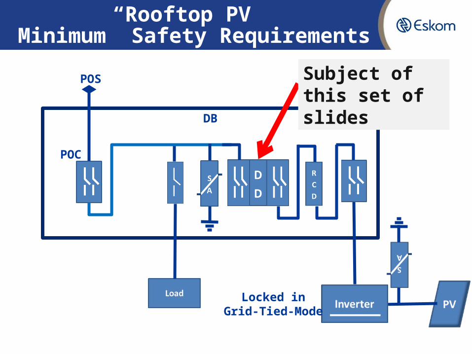
“Rooftop PV” Minimum Safety Requirements
DB
POS
POC
Locked inGrid-Tied-Mode
Subject of this set of slides
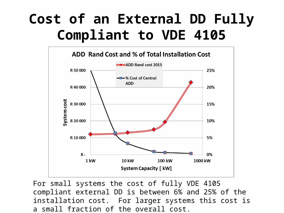
Cost of an External DD Fully Compliant to VDE 4105
For small systems the cost of fully VDE 4105 compliant external DD is between 6% and 25% of the installation cost. For larger systems this cost is a small fraction of the overall cost.
PurposeThe Purpose of this device and the set of slides is to explain the operation of a proposed Automated Disconnecting Device aimed at ensuring that power cannot flow back from a EG once a utility worker has declared this part of the LV network as safe to work on.
It relies on the EG to power down. If this does not happen, the safe work procedure will detect the condition and further steps is to be taken to make the installation safe.
The sole purpose of this device is to secure that once the network is thought to be dead- that it remains so, regardless of any actions or failure of equipment during this time on the EG’s side.
The device comprises of sub-components that are currently regulated in SA and are available on the market and that can meet the “robustness” levels that Eskom would consider adequate for ensuring safety of staff.
This design make the Proof of Compliance and Assurance to Minimum Safety requirements easy to achieve.At reasonable cost for small systems.
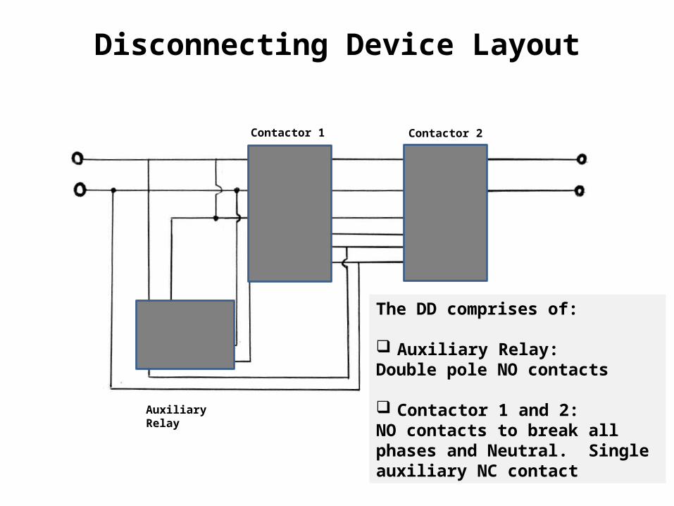
Disconnecting Device Layout
Contactor 1 Contactor 2
Auxiliary Relay
The DD comprises of:
Auxiliary Relay: Double pole NO contacts
Contactor 1 and 2: NO contacts to break all phases and Neutral. Single auxiliary NC contact
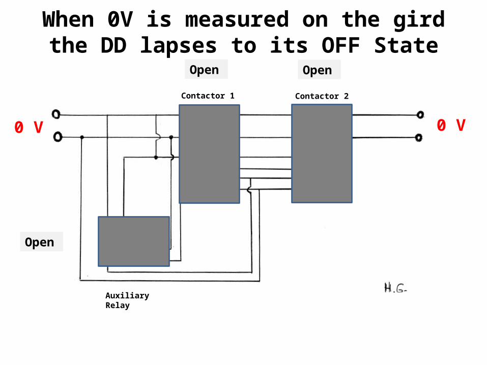
When 0V is measured on the gird the DD lapses to its OFF State
Contactor 1 Contactor 2
Auxiliary Relay
0 V 0 V
Open
Open
Open
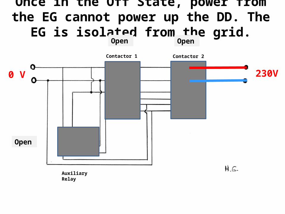
Once in the Off State, power from the EG cannot power up the DD. The EG is isolated from the grid.
Contactor 1 Contactor 2
Auxiliary Relay
0 V 230V
Open
Open
Open
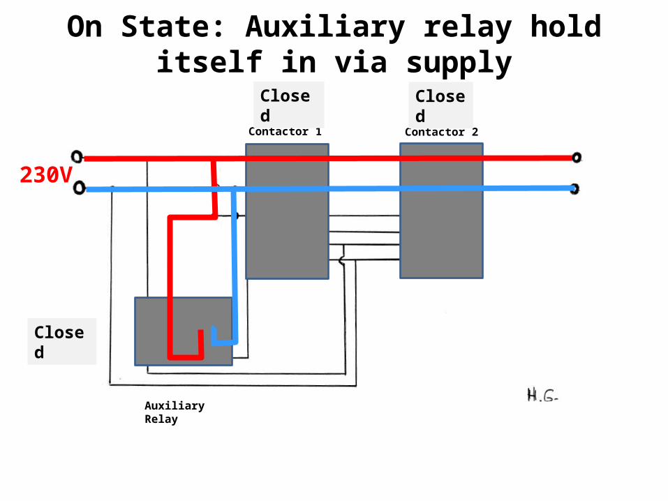
On State: Auxiliary relay hold itself in via supply
Contactor 1 Contactor 2
Auxiliary Relay
230V
Closed
Closed
Closed
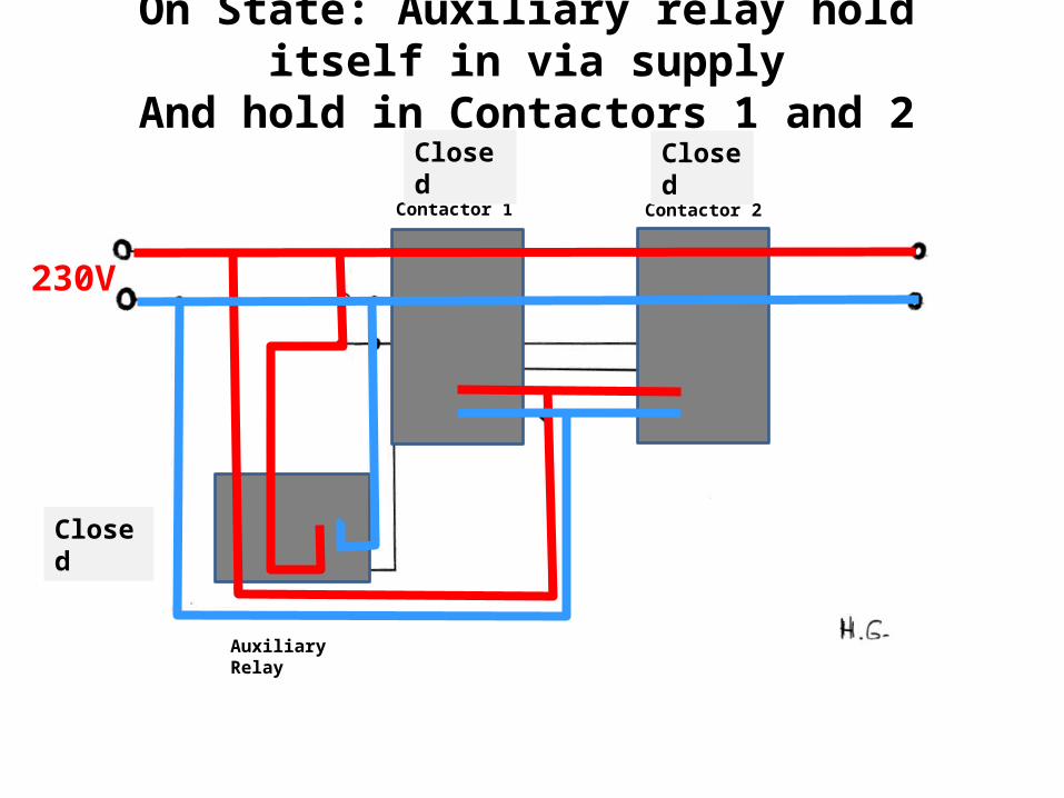
On State: Auxiliary relay hold itself in via supplyAnd hold in Contactors 1 and 2
Contactor 1 Contactor 2
Auxiliary Relay
230V
Closed
Closed
Closed
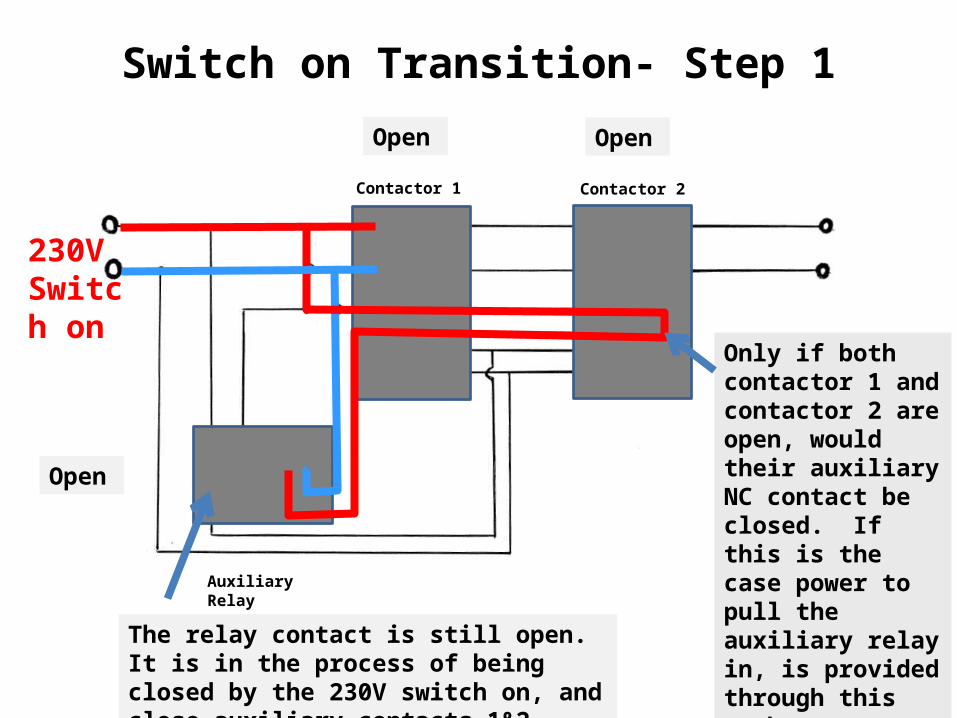
Switch on Transition- Step 1
Contactor 1 Contactor 2
Auxiliary Relay
230VSwitch on
The relay contact is still open. It is in the process of being closed by the 230V switch on, and close auxiliary contacts 1&2
Only if both contactor 1 and contactor 2 are open, would their auxiliary NC contact be closed. If this is the case power to pull the auxiliary relay in, is provided through this path.
Open Open
Open
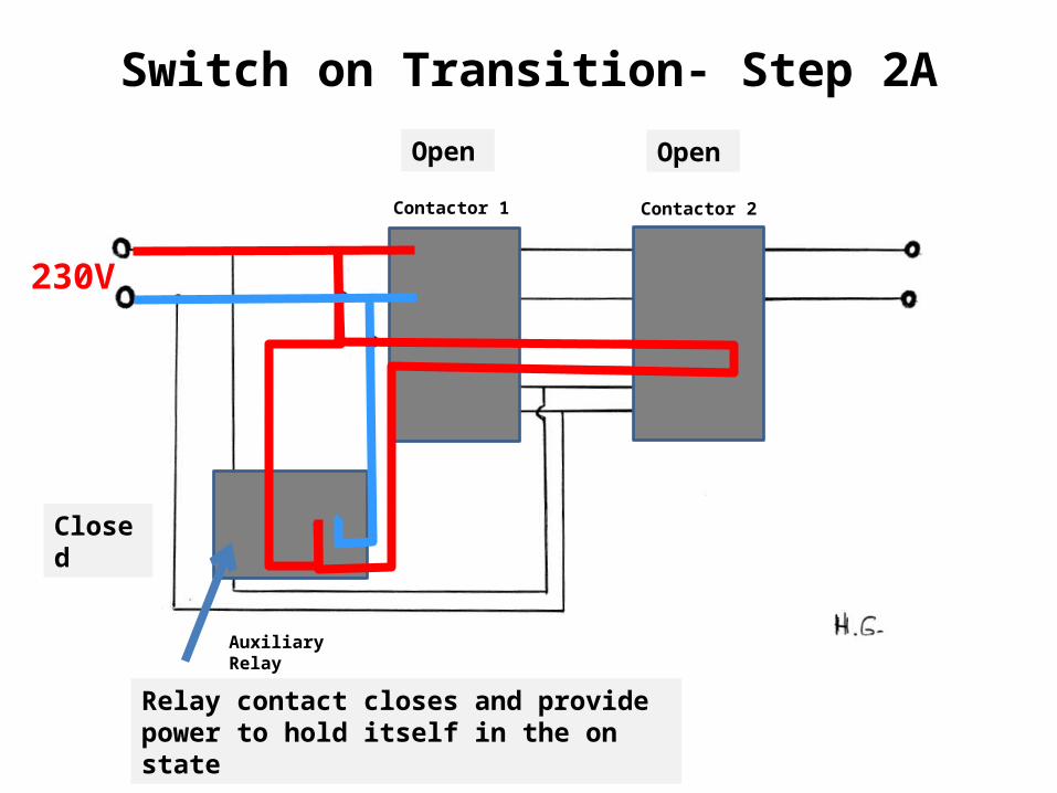
Switch on Transition- Step 2A
Contactor 1 Contactor 2
Auxiliary Relay
230V
Relay contact closes and provide power to hold itself in the on state
Open Open
Closed
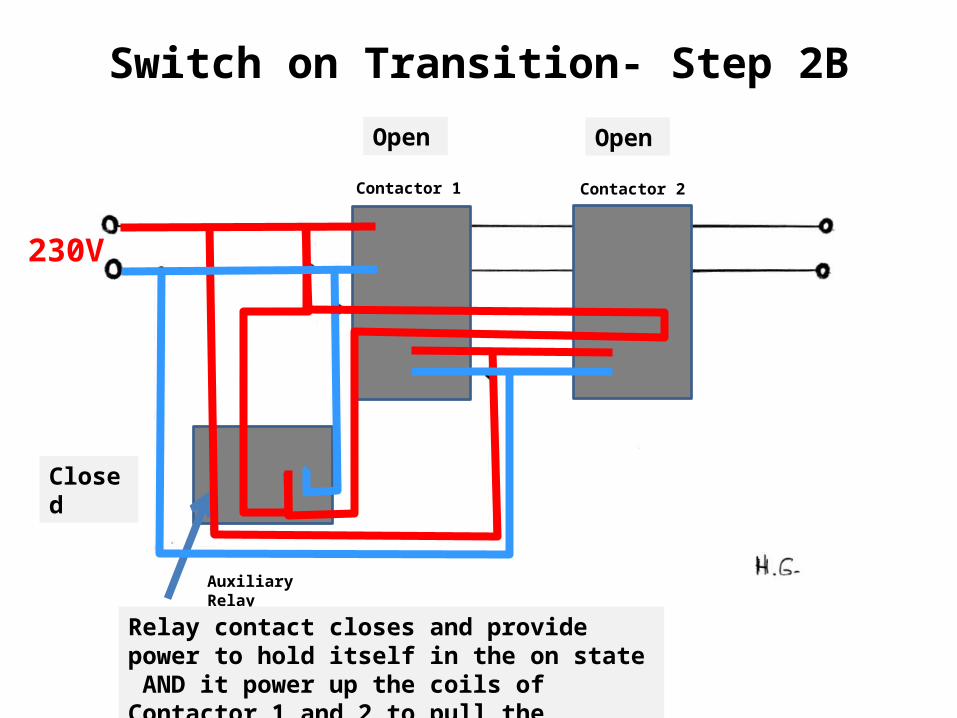
Switch on Transition- Step 2B
Contactor 1 Contactor 2
Auxiliary Relay
230V
Relay contact closes and provide power to hold itself in the on state AND it power up the coils of Contactor 1 and 2 to pull the contactors close.
Open Open
Closed
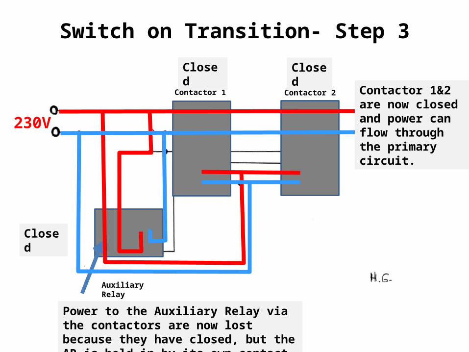
Switch on Transition- Step 3
Contactor 1 Contactor 2
Auxiliary Relay
230V
Power to the Auxiliary Relay via the contactors are now lost because they have closed, but the AR is held in by its own contact
Closed Closed
Closed
Contactor 1&2 are now closed and power can flow through the primary circuit.

On State: Auxiliary relay hold itself in via supplyAnd hold in Contactors 1 and 2
Contactor 1 Contactor 2
Auxiliary Relay
230V
Closed
Closed
Closed
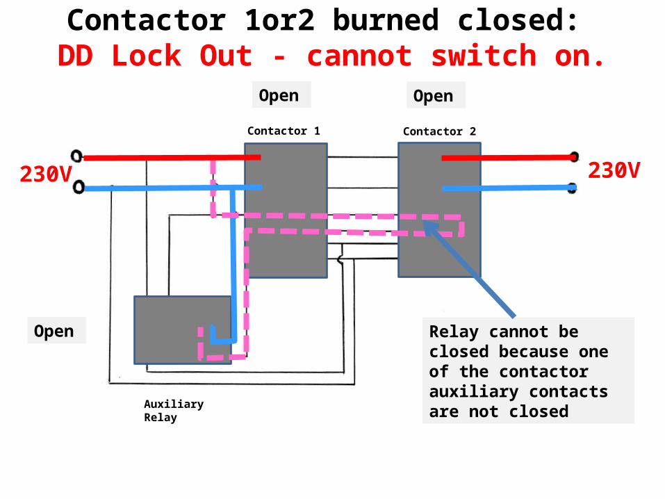
Contactor 1or2 burned closed: DD Lock Out - cannot switch on.
Contactor 1 Contactor 2
Auxiliary Relay
230V
Relay cannot be closed because one of the contactor auxiliary contacts are not closed
Open Open
Open
230V
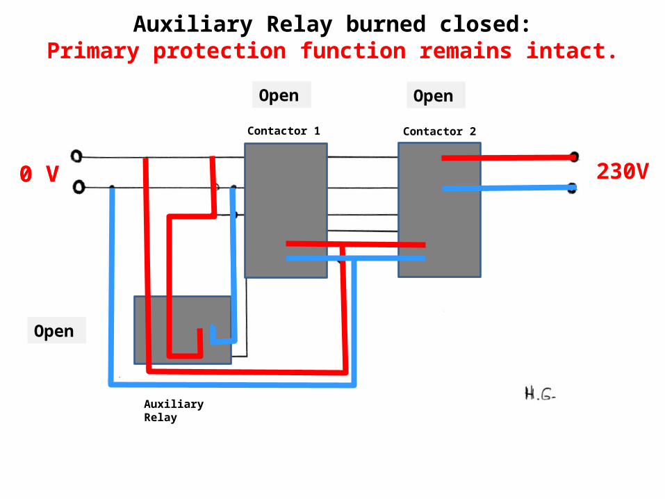
Auxiliary Relay burned closed:Primary protection function remains intact.
Contactor 1 Contactor 2
Auxiliary Relay
Open Open
Open
0 V0 V 230V
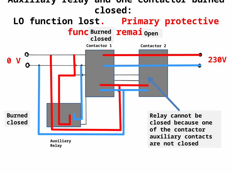
Auxiliary relay and one Contactor burned closed: LO function lost. Primary protective function remains.
Contactor 1 Contactor 2
Auxiliary Relay
Relay cannot be closed because one of the contactor auxiliary contacts are not closed
Open Open
Burned closed
Burned closed
0 V 230V
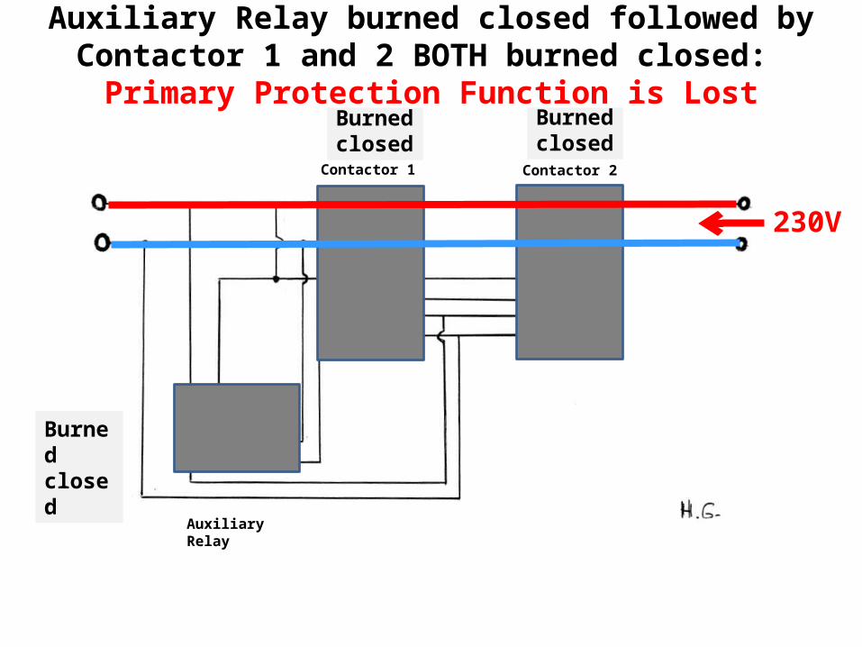
Contactor 1 Contactor 2
Auxiliary Relay
Burned closed
Burned closed
Burned closed
Auxiliary Relay burned closed followed by Contactor 1 and 2 BOTH burned closed:
Primary Protection Function is Lost
230V
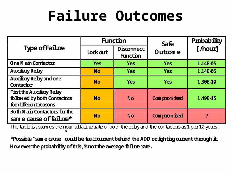
Failure Outcomes
Type of Failure Function Safe
Outcome
Probability [ /hour] Lock out
Disconnect Function
One Main Contactor Yes Yes Yes 1.14E-05 Auxiliary Relay No Yes Yes 1.14E-05 Auxiliary Relay and one Contactor No Yes Yes 1.30E-10
First the Auxiliary Relay followed by both Contactors for different reasons
No No Compromised 1.49E-15
Both Main Contactors for the same cause of failure*
No No Compromised ?
The table is assumes the normal failure rate of both the relay and the contactors as 1 per 10 years.
*Possible “same cause” could be fault current behind the ADD or lighting current through it. However the probability of this, is not the average failure rate.
Same Cause Failure Minimization
• Fault current:Co-ordinate power system protection not to allow damage to the contactors when faults occur.
• Lighting :Suitable lighting protection on both sides ( AC and DC side of inverter ) as well as good bonding of PE and grounding conductors and DC earths is required to minimize this risk.
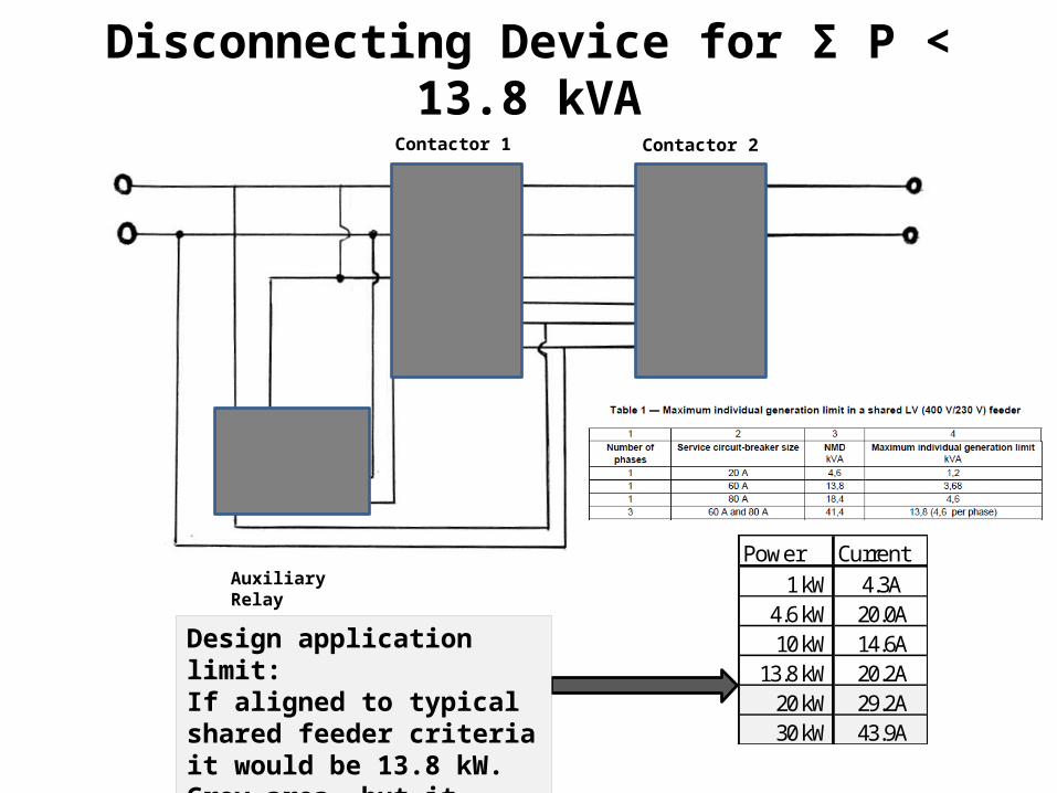
Disconnecting Device for Σ P < 13.8 kVAContactor 1 Contactor 2
Auxiliary Relay
Power Current1 kW 4.3A
4.6 kW 20.0A10 kW 14.6A
13.8 kW 20.2A20 kW 29.2A30 kW 43.9A
Design application limit:If aligned to typical shared feeder criteria it would be 13.8 kW. Grey area- but it could be up to 30A or 50A?
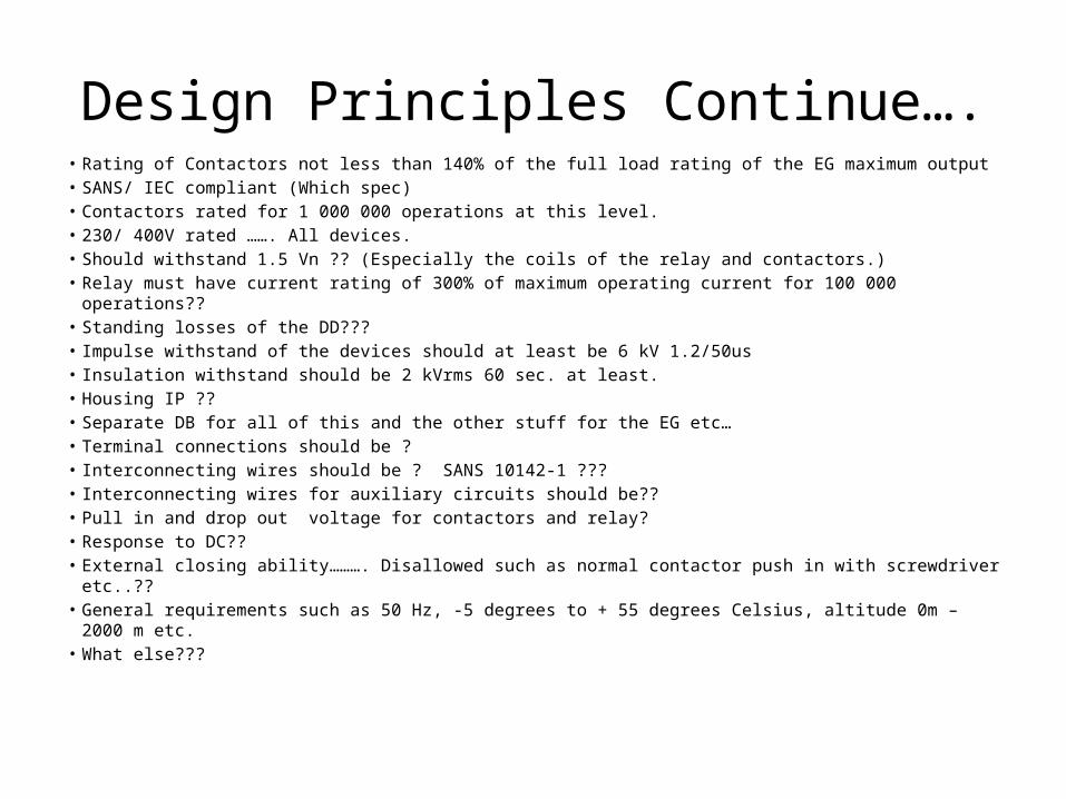
Design Principles Continue….• Rating of Contactors not less than 140% of the full load rating of the EG maximum output• SANS/ IEC compliant (Which spec)• Contactors rated for 1 000 000 operations at this level.• 230/ 400V rated ……. All devices.• Should withstand 1.5 Vn ?? (Especially the coils of the relay and contactors.)• Relay must have current rating of 300% of maximum operating current for 100 000 operations??• Standing losses of the DD???• Impulse withstand of the devices should at least be 6 kV 1.2/50us• Insulation withstand should be 2 kVrms 60 sec. at least.• Housing IP ??• Separate DB for all of this and the other stuff for the EG etc…• Terminal connections should be ?• Interconnecting wires should be ? SANS 10142-1 ???• Interconnecting wires for auxiliary circuits should be??• Pull in and drop out voltage for contactors and relay?• Response to DC??• External closing ability………. Disallowed such as normal contactor push in with screwdriver etc..??• General requirements such as 50 Hz, -5 degrees to + 55 degrees Celsius, altitude 0m – 2000 m etc.• What else???